CARLO GAVAZZI RSGD4025F0VD00 Manual de usuario
- Tipo
- Manual de usuario

RSGD series
General Purpose Soft Starters
INST RSGD 121212 7680021
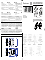
GMS MOUNTING | INSTALLATIONSINSTRUKTIONER FOR GMS |
INSTRUCTIONS DE MONTAGE GMS |
INSTALLATIONSANLEITUNG FÜR GMS | INSTRUCCIONES DE
MONTAJE DE GMS | ISTRUZIONI DI MONTAGGIO GMS
FAN MOUNTING | INSTRUKTIONER TIL MONTERING AF VENTI-
LATOR | INSTRUCTIONS DE MONTAGE DU VENTILATEUR |
INSTALLATIONSANLEITUNG FÜR LÜFTER | INSTRUCCIONES
DE MONTAJE DEL VENTILADOR | ISTRUZIONI DI MONTAGGIO
VENTOLA
ATTENTION
1
. To prevent electrical shock, disconnect from power source
before installing or servicing.
2
. Unauthorised opening of the product will void warranty.
3. “For use in Pollution Degree 2 Environment”.
4. The device should be configured as indicated in the con-
nection diagram. Do not operate the product before all con-
n
ections are completed.
5. The softstarter does not have any integrated short circuit
a
nd overload protection. These must be procured separately.
6. Excessive lengths of cabling should be avoided in view of
E
MC considerations.
7. The RSGD has been designed as Class A equipment. Use
o
f the product in domestic environments can cause radio inter-
ference.
BEMÆRK
1
. For at undgå elektrisk stød, frakobl fra strømkilde før instal-
lation og servicering.
2
. Uautoriseret åbning af produktet vil ugyldiggøre garantien.
3. ”Til brug i miljø med forureningsgrad 2”.
4. Dette udstyr bør konfigureres som angivet i tilslutningsdia-
grammet. Sæt ikke produktet i drift før alle tilslutninger er fore-
t
aget.
5. Softstarteren har ingen indbygget beskyttelse mod kortslut-
n
ing og overbelastning. Disse skal anskaffes separat.
6. Overdreven længde på kabler bør undgås under hensynta-
g
en til EMC (elektromagnetisk kompatibilitet).
7. RSGD er designet og udviklet som udstyr tilhørende klasse
A
. Brug af produktet i private husholdninger kan forårsage
radiostøj.
ACHTUNG
1
. Trennen Sie das Gerät vor der Installation und vor
Wartungsvorgängen von der Stromversorgung, um das Risiko
eines elektrischen Schlags zu vermeiden.
2
. Unerlaubtes Öffnen des Produkts führt zum Verlust der Garantie.
3. „Für die Verwendung in einer Umgebung mit dem
Verschmutzungsgrad 2“.
4
. Das Gerät muss wie im Anschlussdiagramm angegeben
konfiguriert werden. Schalten Sie das Produkt nicht ein, bevor
alle Verbindungen hergestellt sind.
5. Das Sanftstartgerät besitzt keinen integrierten
K
urzschluss- und Überlastschutz. Dieser muss gesondert
bereitgestellt werden.
6. Übermäßig große Kabellängen sollten aus Gründen der
S
törfestigkeit vermieden werden.
7. Das RSGD ist als Gerät der Klasse A nach DIN EN 55011
eingestuft. Die Verwendung im Haushalt kann Funkstörungen
z
ur Folge haben.
IMPORTANT
Carlo Gavazzi is not to be held responsible for incorrect prod-
uct operation or damages resulting from improper use of the
product and/or use of the product outside its specified operat-
ing limits. Products, specifications and data in this document
are subject to change without notice. The product is intended
to be used by qualified personnel at their own discretion and
risk. Should you require information about installation, opera-
tion or maintenance of the product that is not covered in this
document you should refer the matter to an authorized Carlo
Gavazzi representative. The information in this document is
not considered binding on any product warranty.
IMPORTANT
Carlo Gavazzi ne peut être tenu responsable d'une exploita-
tion incorrecte du produit ou d'avaries résultant d'une utilisa-
tion incorrecte du produit et/ou hors des tolérances de fonc-
tionnement spécifiées.
Les produits, caractéristiques et données décrites dans le
présent document peuvent changer sans préavis. L'utilisation
de ce produit est destinée à un personnel qualifié qui l'exploite
à sa guise et à ses propres risques. Pour plus amples infor-
mations concernant l'installation, le fonctionnement ou la
maintenance du produit et ne figurant pas dans ce document,
consulter un concessionnaire agréé Carlo Gavazzi. Les infor-
mations contenues dans ce document ne constituent une obli-
gation de garantie de quelconque nature du produit.
VIGTIGT
Carlo Gavazzi kan ikke holdes ansvarlig for ukorrekt anven-
delse af produktet eller skader opstået ved ukorrekt brug
og/eller efter brug af produktet til andet end de specificerede
driftsbestemmelser. Produkter, specifikationer og data i dette
dokument kan ændres uden varsel. Produktet er beregnet til
anvendelse af uddannet personale efter eget skøn og risiko.
Hvis du har brug for oplysninger om installation, drift eller
vedligeholdelse af produktet, der ikke er dækket af
nærværende dokument, bør du rette henvendelse til en
autoriseret repræsentant fra Carlo Gavazzi. Informationen i
nærværende dokument anses ikke for bindende for nogen
produktgaranti.
IMPORTANTE
C
arlo Gavazzi no se responsabiliza del uso incorrecto del pro-
d
ucto o de los daños ocasionados por un uso incorrecto del
m
ismo y /o por el uso del producto sin tener en cuenta los
l
ímites de funcionamiento especificados. Los equipos,
e
specificaciones y datos recogidos en este documento están
s
ujetos a cambios sin previo aviso. El equipo debe usarse por
p
ersonal cualificado y bajo su responsabilidad y riesgo. En
c
aso de necesitar más información sobre la instalación, fun-
c
ionamiento o mantenimiento del equipo que no se refleje en
e
ste documento, póngase en contacto con un distribuidor
a
utorizado de Carlo Gavazzi. La información detallada en
e
ste documento no se considera vinculante en ninguna
g
arantía del producto.
WICHTIG
Carlo Gavazzi übernimmt keine Haftung für fehlerhafte Bedienung
des Produkts sowie für Schäden, die aus unsachgemäßer
Verwendung des Produkts und/oder dem Einsatz des Produkts
außerhalb der angegebenen Grenzbetriebsdaten resultieren. Die in
diesem Dokument beschriebenen Produkte, Spezifikationen und
technischen Daten können jederzeit ohne vorherige Ankündigung
geändert werden. Das Produkt ist nur für die Verwendung durch
qualifiziertes Fachpersonal nach eigenem Ermessen und auf
eigenesRisikovorgesehen. Wenn Sie Informationen zur Installation,
zum Betrieb oder zur Wartung des Produkts benötigen, die nicht in
dieser Anleitung enthalten sind, wenden Sie sich mit Ihrer Frage an
einen autorisierten Vertriebspartner von Carlo Gavazzi. Die
Informationen in diesem Dokument sind nicht bindend hinsichtlich
der Produktgewährleistung.
IMPORTANTE
C
arlo Gavazzi non può essere ritenuta responsabile per un malfun-
z
ionamento o danni derivanti da un uso improprio del prodotto e/o
u
tilizzo del prodotto al di fuori dei suoi limiti operativi specificati.
P
rodotti, specifiche e dati in questo documento sono soggette a
m
odifichesenza preavviso.Il prodotto è destinatoadessere utilizza-
t
o da personale qualificato a propria discrezione e rischio. Se avete
b
isogno di informazioni su installazione, funzionamento o
m
anutenzione del prodotto non riportate in questo documento,
d
ovete fare riferimento al personale autorizzato Carlo Gavazzi. Le
i
nformazioni contenute in questo documento non sono considerate
v
incolanti per alcuna garanzia sul prodotto.
A
TTENTION
1. Avant toute installation ou intervention, déconnecter la
s
ource d'alimentation pour éviter tout risque d'électrocution.
2. L'ouverture non autorisée du produit annule la garantie.
3. « Pour exploitation en environnement de degré de pollution
2
».
4. Configurer le dispositif comme indiqué dans le schéma des
c
onnexions.Ne pas utiliser le produit tant que toutes les con-
nexions ne sont pas réalisées.
5
. Le démarreur progressif n'intègre aucune protection contre
les courts-circuits/la surcharge.Ces protections doivent être
approvisionnées séparément.
6. Éviter les longueurs excessives de câblage afin de
respecter les normes de compatibilité électromagnétique.
7. De part sa conception, le relais RSGD se trouve répertorié
dans les équipements de Classe A. L’usage de ce relais en
e
nvironnement résidentiel peut provoquer des interférences
radio électriques.
A
TENCIÓN
1. Antes de instalar o revisar el equipo, desconéctelo para
e
vitar descargas eléctricas.
2. La apertura del equipo sin autorización por parte del fabri-
c
ante anula la garantía.
3
. “Para uso en entornos con grado de contaminación 2”
4. El equipo debe configurarse como se indica en el diagrama
d
e conexión. El equipo no debe conectarse hasta que se
hayan realizado todas las conexiones.
5
. El arrancador suave no tiene protección contra cortocir-
cuitos ni sobrecarga. Deben instalarse independientemente.
6
. Hay que evitar una longitud excesiva de los cables, con el
fin de cumplir con los requisitos de compatibilidad electro-
magnética.
7. El controlador RSGD es un equipo de Clase A. El uso de
este producto en entornos domésticos puede causar radioint-
e
rferencias.
A
TTENZIONE
1. Per evitare scosse elettriche, scollegare dalla corrente
p
rima di installare o la manutenzione.
2. L'apertura non autorizzata del prodotto renderà nulla la
g
aranzia.
3
. "Per l'uso in ambiente grado di inquinamento 2".
4. Il dispositivo deve essere configurato come indicato nello
s
chema di collegamento. Non utilizzare il prodotto prima che
tutti i collegamenti sono completati.
5
. Il soft starter non ha nessuna protezione da cortocircuito e
sovraccarico. Questi devono essere installati a parte.
6
. I cavi non devono avere una lunghezza eccessiva per
rispettare le richieste EMC.
7
. Il Soft Start RSGD è un dispositivo progettato in Classe A per
utilizzo in ambiente industriale. Utilizzare questo prodotto in
ambiente domestico può causare radio interferenze .
O
perating Instructions
D
riftsinstruktioner
B
etriebsanweisungen
Instructions de fonctionnement
I
nstrucciones de funcionamiento
Istruzioni opera tive
CONNECTION DIAGRAM | TILSLUTNINGSDIAGRAMMER | ANSCHLUSSDIAGRAMME | DIAGRAMME DE RACCORDEMENT
DIAGRAMA DE CONEXIONES | DIAGRAMMA DELLE CONNESSIONI
RSGD..12.…. up to RSGD..32.….
RSGD..37.…. , RSGD..45.….
RSGD40..E0V.20
RSGD60..GGV.20
RSGD40..E0V.00
RSGD40..F0V.00
RSGD40..E0VX20 with Fan
RSGD40..F0V.20
RSGD40..EV.20
GMS32H
R
TPMGMS32HL
RTPMGMS32SL
M5 (2Nm, 22 lb.in)
Applies to RSGD....Vx..
Applies to RSGD....VD.. models only
GMS32S
DIMENSIONS (MM) | MÅL (MM) | DIMENSIONES (MM) | DIMENSIONS (MM) |ABMESSUNGEN (MM) | DIMENSIONI (MM)
100 - 240VAC
RSGD_121212_2.qxp:RSBS_130208_v2.qxd 1/17/13 12:12 PM Page 1

P
rotection Co-ordination, Type
1 vs Type 2
Type 1 protection implies that after
a
short circuit, the device under
test will no longer be in a
functioning state.
In Type 2 co-ordination the device
under test will still be functional
a
fter the short circuit. In both
cases, however the short circuit
has to be interrupted. The fuse
b
etween enclosure and supply
shall not open. The door or cover
of the enclosure shall not be
b
lown open. There shall be no
damage to conductors or
terminals and the conductors shall
not separate from terminals.
T
here shall be no breakage or
cracking of insulating bases to the
extent that the integrity of the
m
ounting of live parts is impaired.
Discharge of parts or any risk of
fire shall not occur.
T
he product variants listed in the
table hereunder are suitable for
u
se on a circuit capable of
delivering not more than 5,000A
rms Symmetrical Amperes, 600
V
olts maximum when protected
by fuses. Tests at 5,000A were
performed with Class RK5 fuses,
f
ast acting; please refer to the
table below for maximum allowed
ampere rating of the fuse. Use
f
uses only.
B
eskyttelseskoordinering,
type 1 kontra type 2:
Type-1-beskyttelse indebærer,
a
t den testede enhed efter en
kortslutning ikke længere er
funktionsduelig. Ved type-2-
k
oordinering er den testede
anordning fortsat funktionsdu-
elig efter kortslutningen. I
b
egge tilfælde skal kortslutnin-
gen imidlertid afbrydes.
Sikringen mellem kabinettet og
f
orsyningen må ikke gå op.
Kabinettets låge eller dæksel
må ikke sprænges åben. Der
m
å ikke ske beskadigelse af
ledere eller klemmer, og led-
erne må ikke løsne sig fra
klemmerne. Der må ikke ske
b
rud eller revnedannelse i iso-
leringen af et omfang, så fast-
gørelsen af spændingssatte
d
ele påvirkes. Der må ikke ske
udladning i komponenter eller
være brandfare.
D
e produktvarianter, der
fremgår af nedenstående
t
abel, er egnede til brug i en
kreds, der højst kan levere
5.000 Arms symmetrisk strøm,
m
aksimalt 600 V beskyttet af
sikringer. Der er udført test ved
5.000 A med tidsforsinkede
R
K5-sikringer, Den maksimalt
tilladte nominelle strømstyrke
af sikringen fremgår af
t
abellen. Der må kun benyttes
sikringer.
C
oordination de protection,
comparatif Type 1 et Type 2:
La protection de type 1 implique
q
u'après un court-circuit, le relais
testé n'est plus à l'état fonctionnel.
En protection de type 2, le relais
t
esté demeure à l'état fonctionnel
après court-circuit. Cependant,
dans les deux cas le circuit doit
ê
tre protégé. Le fusible entre le
boîtier et l'alimentation doit être
intègre. La trappe ou le couvercle
d
e l'enceinte ne doivent pas avoir
été soulevés par l'air rejeté. Les
conducteurs ou les bornes ne
d
oivent présenter aucune avarie
et les conducteurs ne doivent pas
être désolidarisés des bornes. Il
ne doit y avoir ni rupture ni
f
issuration des bases isolantes
susceptibles d'affecter l'intégrité
du montage des parties sous
t
ension. Il ne peut y avoir aucune
décharge des pièces ni aucun
risque d'incendie.
L
'utilisation des variantes du
produit (voir tableau suivant)
c
onvient à un circuit protégé par
fusibles, délivrant 5,000 A (eff.)
symétriques ou moins à 600 V
m
aximum. Des tests à 5.000A ont
été effectués avec des fusibles
rapides de Classe RK5 : le
t
ableau ci-dessous spécifie
l'ampérage maximal autorisé pour
le fusible. Utiliser uniquement des
f
usibles.
S
chutzkoordinierung, Typ 1
gegen Typ 2:
T
yp-1 bedeutet, dass sich das zu
prüfende Gerät nach einem
Kurzschluss nicht länger im
F
unktionszustand befindet. Beim
Typ 2 ist das zu prüfende Gerät
nach einem Kurzschluss immer
n
och einsatzbereit. In beiden Fällen
mussder Kurzschluss beendet sein.
Die Testsicherung zwischen
G
ehäuse und Versorgung darf nicht
ausgelöst haben. Die Tür bzw.
Abdeckung des Gehäuses darf
n
icht aufgesprengt werden. An den
Leitern oder Anschlussklemmen
dürfen keine Schäden entstanden
s
ein und die Leiter dürfen sich nicht
von den Anschlussklemmen gelöst
haben. Die Isolierung darf nicht so
weit aufgebrochen oder gerissen
sein, dass die Betriebssicherheit der
H
alterung von stromführenden
Teilen beeinträchtigt ist. Es dürfen
keine Teile weggeschleudert werden
u
nd es darf keine Brandgefahr
bestehen. Die in der nachstehenden
Tabelle aufgeführten Varianten sind
geeignet für den Einsatz in einem
S
tromkreis, der bei Schutz durch
Sicherungen höchstens einen
symmetrischen Strom von
5
.000 Aeff effektiv und eine
Spannung von maximal 600 Volt
liefern kann. Die Prüfungen bei
5
.000 Aeff wurden mit superflinken
Sicherungen, Klasse RK5
durchgeführt. Die folgende Tabelle
z
eigt den maximal zulässigen
Nennstrom der Sicherung. Nur
Schmelzsicherungen verwenden.
C
oordinazione protezioni, Tipo
1 vs Tipo 2:
Tipo 1 presuppone che dopo un
c
orto circuito, il dispositivo in
prova non sarà più in uno stato
funzionante. Nel tipo 2 il
c
oordinamento del dispositivo in
prova sarà ancora funzionante
dopo il corto circuito. In entrambi i
c
asi, tuttavia il corto circuito deve
essere interrotto. Il fusibile non è
aperto. La porta o il coperchio del
c
ontenitore non deve essere
aperto. Non devono essere
danneggiati i conduttori e i
t
erminali. Non ci devono essere
rotture e screpolature delle basi
isolanti nella misura in cui
l'integrità del montaggio e delle
p
arti in tensione è alterata. Rotture
o rischio di incendi non devono
avvenire.
L
e varianti di prodotti elencati
nella tabella che segue sono
adatti per l'uso su un circuito in
g
rado di fornire non più di 5.000
Arms simmetrici, 600 volt
m
assimo, se protetto da fusibili.
Prove a 5.000 sono state eseguite
con fusibili RK5, tempo di ritardo,
s
i prega di fare riferimento alla
seguente tabella per l’amperaggio
massimo consentito del fusibile.
U
tilizzare solo fusibili.
C
oordinación de protección de
tipo 1 en comparación con el
tipo 2:
T
ipo 1: implica que después de un
cortocircuito, el equipo en prueba
no volverá al estado de
f
uncionamiento. Tipo 2: el equipo
en prueba es operativo después
de un cortocircuito. En ambos
c
asos, sin embargo hay que
interrumpir el cortocircuito. No hay
que abrir el fusible entre la caja y
l
a alimentación. La puerta o la
cubierta de la caja no debe
abrirse bruscamente. Los
c
onductores o terminales no
deben estar dañados y los
conductores no deben estar
separados de los terminales. No
d
ebe haber rotura o fisura en la
base de aislamiento de manera
que la integridad del montaje de
l
as partes vivas muestre
deterioro. No deben ocurrir
descargas o darse riesgo de
i
ncendios.
Las variables del producto
r
eflejadas en la tabla a
continuación pueden usarse en
un circuito capaz de soportar más
d
e 5.000 amperios eficaces (rms)
simétricos, 600V de tensión
máxima cuando la protección sea
p
or fusibles. Pruebas realizadas a
5.000 A con fusibles RK5; por
favor consulte a continuación los
a
mperios máximos permitidos por
el fusible. Utilice sólo fusibles.
Co-ordination Type 1 (UL508) – Time Delay Fuses
Part. No.
Max. Fuse Size [A]
Class Current [kA]
Max. Voltage [VAC]
RSGD..12.V….
20
RK5
5
400 / 600
RSGD..16.V….
20
RK5
5
400 / 600
RSGD..25.V….
25
RK5
5
400 / 600
RSGD..32.V….
35
RK5
5
400 / 600
RSGD..37.V….
50
RK5
5
400 / 600
RSGD..45.V….
50
RK5
5
400 / 600
Co-ordination Type 1 - Manual Motor Starters
Part. No. Class Current [kA]
M
ax. Voltage [VAC]
RSGD..12.V…. GMS32S-17/ GMS32H-17 10 400 / 600
RSGD..16.V…. GMS32S-17/ GMS32H-17 10 400 / 600
RSGD..25.V…. GMS32H-32 10 400 / 600
RSGD..32.V…. GMS32H-32 10 400 / 600
RSGD..37.V…. GMS63S-50/ GMS63H-50 10 400 / 600
RSGD..45.V…. GMS63S-50/ GMS63H-50 10 400 / 600
Co-ordination Type 2 9IEC/EN 60947-4-2) - Semiconductor Fuses
Part. No.
Max. Fuse Size [A]
Class Current [kA]
Max. Voltage [VAC]
RSGD..12.V….
35 A70 QS 35-4 5
400 / 600
RSGD..16.V….
35 A70 QS 35-4 5
400 / 600
RSGD..25.V….
60/63 A70 QS 60-4/ 6.9xxCP URD 22 x 58/63 (xx = 00 or 21) 5
400 / 600
RSGD..32.V….
60/63 A70 QS 60-4/ 6.9xxCP URD 22 x 58/63 (xx = 00 or 21) 5
400 / 600
RSGD..37.V….
125 A70 QS 125-4 5
400 / 600
RSGD..45.V….
125 A70 QS 125-4 5
400 / 600
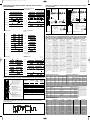
SHORT CIRCUIT PROTECTION (ACCORDING TO EN/IEC 60947-4-2 AND UL508) | PROTECCIÓN CONTRA CORTOCIRCUITOS
(SEGÚN EN/IEC 60947-4-2 Y UL508) | KORTSLUTNINGSBESKYTTELSE (IHT. EN/IEC 60947-4-2 OG UL508) | PROTECTION
CONTRE LES COURTS-CIRCUITS (CONFORMÉMENT À EN/IEC 60947-4-2 ET À UL508) KURZSCHLUSSSCHUTZ (GEMÄSS
EN/IEC 60947-4-2 UND UL508) | PROTEZIONE DA CORTO CIRCUITO(SECONDO LE NORME EN / IEC 60947-4-2 E UL508)
CURRENT / POWER RATINGS @ 40˚C
MODE OF OPERATION - DRIFTSFORM - MODE DE FONCTIONNEMENT - BETRIEBSMODUS - MODO DE FUNCIONAMIENTO
MODALITÀ DI FUNZIONAMENTO
SOFT STARTER SETTING PROCEDURE - INDSTILLINGSPROCEDURE FOR SOFTSTARTER - PROCÉDURE DE CONFIGURATION D'UN DÉMARREUR
PROGRESSIF - EINSTELLVORGANG FÜR DAS SANFTSTARTGERÄT - CONFIGURACIÓN DELARRANCADOR SUAVE - PROCEDURA DI AVVIAMENTO SOFT
N
ormal Condi
o
n
M
ains Voltage
G
reen LED
R
ed LED
Control Voltage
Controller Output
R
elay Contact (Bypassed)**
R
elay Contact (Alarm)
dŚĞ ĨƵŶĐƟŽŶĂůŝƚLJ ŽĨ ƚŚŝƐ ĂůĂƌŵ ŝƐ ĨŽƌ ŝŶĚŝĐĂƟŽŶ ƉƵƌƉŽƐĞƐ ŽŶůLJ ĂŶĚ ŝƐ ŶŽƚ ĐŽŶƐŝĚĞƌĞĚ Ă ŵĞĂŶƐ
t
o protect against over current.
1 sec
>
= 1 sec
<
1 sec
1
sec
1
sec
Wrong Phase Sequence
2L1L
1
L2L
3
L3L
Green LED
Red LED
C
ontrol Voltage
C
ontroller Output
Relay Contact (Bypassed)**
Relay Contact (Alarm)
L
3
L
2
L1
Mains Voltage
U
ndervoltage Condi
o
n
Green LED
Red LED
Control Voltage
Controller Output
Relay Contact (Bypassed)**
Relay Contact (Alarm)
Mains Voltage
< 1sec => 1sec
5 mins recovery
1 sec
Overcurrent Condi on (during Ramping)
(>Ie + 15%)
Green LED
Red LED
Control Voltage
C
ontroller Output
Over Current Condi
on
(
>4xIe)
R
elay Contact (Bypassed)**
R
elay Contact (Alarm)
Two Consecu ve
Alarms
1 sec
5mins
5
mins recovery
1 sec
5mins
A
larm does not
self-recover
Mains Voltage
switching OFF and re-applying power to the so starter
User Interven
on required to reset device by
5mins recovery
LED con
nues Ňashing
1 sec
Overcurrent Cond n (during Bypass)*
(> Ie +15%)
User Interven on required to reset device by
switching OFF and re-applying power to the so starter
Two Consecu
ve Alarms
5mins
5mins recovery
Two Consecu
ve Alarms
Alarm does not
self-recover
L
ED con
nues
Ňashing
1min*
1sec
5mins
1min*
User Interven on required to reset device by
switching OFF and re-applying power to the so
starter
>1sec >1sec
1
sec
5
mins
5mins recovery
1sec
5mins
5mins recovery >1sec
Two Consecu
ve Alarms
LED con
nues Ňashing
Alarm does not
self-
recover
5
mins recovery
Green LED
Red LED
Control Voltage
Controller Output
Relay Contact (Bypassed)**
Relay Contact (Alarm)
Mains Voltage
Ramp-Up Time >1sec Alarm
Green LED
Red LED
Control Voltage
C
ontroller Output
Over Current Condi
on
(>Ie + 15%)
Relay Contact (Bypassed)**
Relay Contact (Alarm)
Mains Voltage
N
ormal Condition
O
vercurrent Condition (during ramping)
(
>4x le during ramp-up)
W
rong Phase Sequence
U
ndervoltage condition
Ramp-Up Time > 1 sec. alarm
O
vercurrent condition (during bypass)
(> le +15%)
FLASHING SEQUENCE | BLINKENDE SEKVENS | BLINKFREQUENZ | SÉQUENCE DE CLIGNOTEMENT | SECUENCIA DE PARPADEO |
SEQUENZA LAMPEGGIANTE
Part no. IEC Rated Current 220 - 240 VAC 380 - 415 VAC 440 - 480 VAC 550 - 600 VAC
RSGD4012..... 12 AAC 3 kW/ 3 HP 5.5 kW/ 5 HP --
RSGD4016..... 16 AAC 4 kW/ 5 HP 7.5 kW/ 7.5 HP --
RSGD4025..... 25 AAC 5.5 kW/ 7.5 HP 11 kW/ 10 HP --
RSGD4032..... 32 AAC 9 kW/ 10 HP 15 kW/ 15 HP --
RSGD4037..... 37 AAC 9 kW/ 10 HP 18.5 kW/ 20 HP --
RSGD4045..... 45 AAC 11 kW/ 15 HP 22 kW/ 25 HP --
RSGD6012..... 12 AAC 3 kW/ 3 HP 5.5 kW/ 5 HP 5.5 kW/ 7.5 HP 9 kW/ 10 HP
RSGD6016..... 16 AAC 4 kW/ 5 HP 7.5 kW/ 7.5 HP 9 kW/ 10 HP 11 kW/ 15 HP
RSGD6025..... 25 AAC 5.5 kW/ 7.5 HP 11 kW/ 10 HP 11 kW/ 15 HP 20 kW/ 20 HP
RSGD6032..... 32 AAC 9 kW/ 10 HP 15 kW/ 15 HP 18.5 kW/ 20 HP 22 kW/ 30 HP
RSGD6037..... 37 AAC 9 kW/ 10 HP 18.5 kW/ 20 HP 22 kW/ 25 HP 30 kW/ 30 HP
RSGD6045..... 45 AAC 11 kW/ 15 HP 22 kW/ 25 HP 22 kW/ 30 HP 37 kW/ 40 HP
Step 1: Adjust Starting Voltage (0 - 85%)
Trin 1: Justér den indledende spænding
Phase 1: Réglage de la tension initiale
Schritt 1: Anfangsspannung einstellen
Fase 1: Regolare la tensione iniziale
Paso 1: Ajuste de la tensión inicial
Step 2: Adjust Starting Time (1-20s)
Trin 2: Justér starttiden
Phase 2: Réglage du temps d'accélération
Schritt 2: Anlaufzeit einstellen
Fase 2: Regolare il tempo di accelerazione
Paso 2: Ajuste del tiempo de rampa ascendente
Step 3: Adjust Stopping Time (0 - 20s)
Trin 3: Justér sluktiden
Phase 3: Réglage du temps de décélération
Schritt 3: Auslaufzeit einstellen
Fase 3: Regolare il tempo di decelerazione
Paso 3: Ajuste del tiempo de rampa descendente
TERMINAL DIAGRAM | KLEMMEDIAGRAM | DIAGRAMA DE TERMINALES | ANSCHLUSSBILD | IMPLANTATION DES BORNES |
DISPOSIZIONE DEI TERMINALI
RSGD40...
Use 75
O
C copper (Cu)
conductors
Use 75
O
C copper (Cu)
conductors
RSGD60...
Application Initial Voltage Ramp-up Ramp-down
time (sec) time (sec)
Hydraulic lifts 40% 20
Piston compressor 40% 30
Screw compressor 50% 10 0
Scroll compressor 40% 10
Low inertia fan 40% 10 0
High inertia fan 40% 15 – 20 0
Pump 40% 10 10
Centrifugal blower 40% 50
Conveyor 50% 10 5
* Note: Products rated 12A and 16A, pro-
tected with manual motor starters must
be wired with a minimum length of 15m of
Cu wire conductor with a minimum cross
sectional area of 2.5mm². Products rated
25A or higher, protected with manual
motor starters must be wired with a mini-
mum length of 10m of Cu wire conductor.
The length includes the conductors from
the voltage source to the manual manual
starter, from the manual motor starter to
the soft starter and from the soft starter to
the load.
Pozidrive Bit 0
0.6Nm (5.3 lb.in)
Pozidrive Bit 2
2.5Nm (22 lb.in)
2.5 ... 10mm
2
2 x 2.5 .... 4mm
2
AWG 6 ... 14
AWG 2 x 20 ...
L1, L2, L3: Line connections
T1, T2, T3: Load connections
A1, A2: Control voltage
1
1, 12*: Alarm indication
(Normally Closed, NC)
21, 24*: Top of Ramp indication
(Normally Open, NO)
F1, F2*: External 24VDC supply for fan
(if fan is used)
* applies to RSGD40..Vx.. versions only
8
.0mm
Rigid:
AWG 10 ... 14
0.5 ... 2.5mm
2
AWG 10 ... 18
6.0mm
6.0mm
11, 12, 21, 24* :
0.05 ... 2.5mm
2
AWG 30... 12
11, 12, 14**
0.2 ... 4mm
2
AWG 24... 12
P
ozidrive Bit 0
0.6Nm (5.3 lb.in)
Pozidrive Bit 2
2.5Nm (22 lb.in)
2.5 ... 10mm
2
2 x 2.5 .... 4mm
2
AWG 6 ... 14
AWG 2 x 20 ...
L
1, L2, L3: Line connections
T1, T2, T3: Load connections
A1, A2: Supply voltage
11, 12*: Alarm indication (Normally Closed, NC)
21, 24*: Top of Ramp indication
(Normally Open, NO)
11, 12, 14**: Alarm indication (Normally Open,
Normally Closed, Changeover
contact)
ST: Start / Stop signal
F1, F2*: External 24VDC supply for fan
(if fan is used)
* Applies to RSBD40..V61HP versions only
** Applies to RSBT....EV..1.. models only (using RFPM module)
8.0mm
Rigid:
AWG 10 ... 14
0.5 ... 2.5mm
2
AWG 10 ... 18
6.0mm
6.0mm
11, 12, 21, 24* :
0.05 ... 2.5mm
2
AWG 30... 12
1
1, 12, 14**
0
.2 ... 4mm
2
AWG 24... 12
RSGD_121212_2.qxp:RSBS_130208_v2.qxd 1/17/13 12:15 PM Page 2
Transcripción de documentos
RSGD_121212_2.qxp:RSBS_130208_v2.qxd 1/17/13 12:12 PM Page 1 ATTENTION BEMÆRK 2. Unauthorised opening of the product will void warranty. 2. Uautoriseret åbning af produktet vil ugyldiggøre garantien. 1. To prevent electrical shock, disconnect from power source before installing or servicing. 3. “For use in Pollution Degree 2 Environment”. 4. The device should be configured as indicated in the connection diagram. Do not operate the product before all connections are completed. 5. The softstarter does not have any integrated short circuit and overload protection. These must be procured separately. 6. Excessive lengths of cabling should be avoided in view of EMC considerations. 7. The RSGD has been designed as Class A equipment. Use of the product in domestic environments can cause radio interference. 1. For at undgå elektrisk stød, frakobl fra strømkilde før installation og servicering. 3. ”Til brug i miljø med forureningsgrad 2”. 4. Dette udstyr bør konfigureres som angivet i tilslutningsdiagrammet. Sæt ikke produktet i drift før alle tilslutninger er foretaget. 5. Softstarteren har ingen indbygget beskyttelse mod kortslutning og overbelastning. Disse skal anskaffes separat. 6. Overdreven længde på kabler bør undgås under hensyntagen til EMC (elektromagnetisk kompatibilitet). 7. RSGD er designet og udviklet som udstyr tilhørende klasse A. Brug af produktet i private husholdninger kan forårsage radiostøj. ACHTUNG 1. Trennen Sie das Gerät vor der Installation und vor Wartungsvorgängen von der Stromversorgung, um das Risiko eines elektrischen Schlags zu vermeiden. 2. Unerlaubtes Öffnen des Produkts führt zum Verlust der Garantie. 7. Das RSGD ist als Gerät der Klasse A nach DIN EN 55011 eingestuft. Die Verwendung im Haushalt kann Funkstörungen zur Folge haben. 2. L'ouverture non autorisée du produit annule la garantie. 2. La apertura del equipo sin autorización por parte del fabricante anula la garantía. 2. L'apertura non autorizzata del prodotto renderà nulla la garanzia. 4. El equipo debe configurarse como se indica en el diagrama de conexión. El equipo no debe conectarse hasta que se hayan realizado todas las conexiones. 4. Il dispositivo deve essere configurato come indicato nello schema di collegamento. Non utilizzare il prodotto prima che tutti i collegamenti sono completati. 4. Configurer le dispositif comme indiqué dans le schéma des connexions.Ne pas utiliser le produit tant que toutes les connexions ne sont pas réalisées. 5. Le démarreur progressif n'intègre aucune protection contre les courts-circuits/la surcharge.Ces protections doivent être approvisionnées séparément. 6. Éviter les longueurs excessives de câblage afin de respecter les normes de compatibilité électromagnétique. 7. De part sa conception, le relais RSGD se trouve répertorié dans les équipements de Classe A. L’usage de ce relais en environnement résidentiel peut provoquer des interférences radio électriques. IMPORTANT Carlo Gavazzi is not to be held responsible for incorrect product operation or damages resulting from improper use of the product and/or use of the product outside its specified operating limits. Products, specifications and data in this document are subject to change without notice. The product is intended to be used by qualified personnel at their own discretion and risk. Should you require information about installation, operation or maintenance of the product that is not covered in this document you should refer the matter to an authorized Carlo Gavazzi representative. The information in this document is not considered binding on any product warranty. IMPORTANT Carlo Gavazzi ne peut être tenu responsable d'une exploitation incorrecte du produit ou d'avaries résultant d'une utilisation incorrecte du produit et/ou hors des tolérances de fonctionnement spécifiées. Les produits, caractéristiques et données décrites dans le présent document peuvent changer sans préavis. L'utilisation de ce produit est destinée à un personnel qualifié qui l'exploite à sa guise et à ses propres risques. Pour plus amples informations concernant l'installation, le fonctionnement ou la maintenance du produit et ne figurant pas dans ce document, consulter un concessionnaire agréé Carlo Gavazzi. Les informations contenues dans ce document ne constituent une obligation de garantie de quelconque nature du produit. 3. “Para uso en entornos con grado de contaminación 2” 5. El arrancador suave no tiene protección contra cortocircuitos ni sobrecarga. Deben instalarse independientemente. 6. Hay que evitar una longitud excesiva de los cables, con el fin de cumplir con los requisitos de compatibilidad electromagnética. 7. El controlador RSGD es un equipo de Clase A. El uso de este producto en entornos domésticos puede causar radiointerferencias. VIGTIGT Carlo Gavazzi kan ikke holdes ansvarlig for ukorrekt anvendelse af produktet eller skader opstået ved ukorrekt brug og/eller efter brug af produktet til andet end de specificerede driftsbestemmelser. Produkter, specifikationer og data i dette dokument kan ændres uden varsel. Produktet er beregnet til anvendelse af uddannet personale efter eget skøn og risiko. Hvis du har brug for oplysninger om installation, drift eller vedligeholdelse af produktet, der ikke er dækket af nærværende dokument, bør du rette henvendelse til en autoriseret repræsentant fra Carlo Gavazzi. Informationen i nærværende dokument anses ikke for bindende for nogen produktgaranti. IMPORTANTE Carlo Gavazzi no se responsabiliza del uso incorrecto del producto o de los daños ocasionados por un uso incorrecto del mismo y /o por el uso del producto sin tener en cuenta los límites de funcionamiento especificados. Los equipos, especificaciones y datos recogidos en este documento están sujetos a cambios sin previo aviso. El equipo debe usarse por personal cualificado y bajo su responsabilidad y riesgo. En caso de necesitar más información sobre la instalación, funcionamiento o mantenimiento del equipo que no se refleje en este documento, póngase en contacto con un distribuidor autorizado de Carlo Gavazzi. La información detallada en este documento no se considera vinculante en ninguna garantía del producto. GMS32S 6. Übermäßig große Kabellängen sollten aus Gründen der Störfestigkeit vermieden werden. ATTENZIONE 3. « Pour exploitation en environnement de degré de pollution 2». GMS32H 4. Das Gerät muss wie im Anschlussdiagramm angegeben konfiguriert werden. Schalten Sie das Produkt nicht ein, bevor alle Verbindungen hergestellt sind. 5. Das Sanftstartgerät besitzt keinen integrierten Kurzschluss- und Überlastschutz. Dieser muss gesondert bereitgestellt werden. ATENCIÓN 1. Antes de instalar o revisar el equipo, desconéctelo para evitar descargas eléctricas. General Purpose Soft Starters 3. „Für die Verwendung in einer Umgebung mit dem Verschmutzungsgrad 2“. ATTENTION 1. Avant toute installation ou intervention, déconnecter la source d'alimentation pour éviter tout risque d'électrocution. GMS MOUNTING | INSTALLATIONSINSTRUKTIONER FOR GMS | INSTRUCTIONS DE MONTAGE GMS | INSTALLATIONSANLEITUNG FÜR GMS | INSTRUCCIONES DE MONTAJE DE GMS | ISTRUZIONI DI MONTAGGIO GMS RSGD series 1. Per evitare scosse elettriche, scollegare dalla corrente prima di installare o la manutenzione. 3. "Per l'uso in ambiente grado di inquinamento 2". 5. Il soft starter non ha nessuna protezione da cortocircuito e sovraccarico. Questi devono essere installati a parte. 6. I cavi non devono avere una lunghezza eccessiva per rispettare le richieste EMC. RTPMGMS32HL INST RSGD 121212 7680021 Operating Instructions Driftsinstruktioner Betriebsanweisungen RTPMGMS32SL Instructions de fonctionnement Instrucciones de funcionamiento Applies to RSGD....VD.. models only Istruzioni operative M5 (2Nm, 22 lb.in) FAN MOUNTING | INSTRUKTIONER TIL MONTERING AF VENTILATOR | INSTRUCTIONS DE MONTAGE DU VENTILATEUR | INSTALLATIONSANLEITUNG FÜR LÜFTER | INSTRUCCIONES DE MONTAJE DEL VENTILADOR | ISTRUZIONI DI MONTAGGIO VENTOLA 7. Il Soft Start RSGD è un dispositivo progettato in Classe A per utilizzo in ambiente industriale. Utilizzare questo prodotto in ambiente domestico può causare radio interferenze . WICHTIG Carlo Gavazzi übernimmt keine Haftung für fehlerhafte Bedienung des Produkts sowie für Schäden, die aus unsachgemäßer Verwendung des Produkts und/oder dem Einsatz des Produkts außerhalb der angegebenen Grenzbetriebsdaten resultieren. Die in diesem Dokument beschriebenen Produkte, Spezifikationen und technischen Daten können jederzeit ohne vorherige Ankündigung geändert werden. Das Produkt ist nur für die Verwendung durch qualifiziertes Fachpersonal nach eigenem Ermessen und auf eigenes Risiko vorgesehen. Wenn Sie Informationen zur Installation, zum Betrieb oder zur Wartung des Produkts benötigen, die nicht in dieser Anleitung enthalten sind, wenden Sie sich mit Ihrer Frage an einen autorisierten Vertriebspartner von Carlo Gavazzi. Die Informationen in diesem Dokument sind nicht bindend hinsichtlich der Produktgewährleistung. IMPORTANTE Carlo Gavazzi non può essere ritenuta responsabile per un malfunzionamento o danni derivanti da un uso improprio del prodotto e/o utilizzo del prodotto al di fuori dei suoi limiti operativi specificati. Prodotti, specifiche e dati in questo documento sono soggette a modifiche senza preavviso.Il prodotto è destinato ad essere utilizzato da personale qualificato a propria discrezione e rischio. Se avete bisogno di informazioni su installazione, funzionamento o manutenzione del prodotto non riportate in questo documento, dovete fare riferimento al personale autorizzato Carlo Gavazzi. Le informazioni contenute in questo documento non sono considerate vincolanti per alcuna garanzia sul prodotto. Applies to RSGD....Vx.. CONNECTION DIAGRAM | TILSLUTNINGSDIAGRAMMER | ANSCHLUSSDIAGRAMME | DIAGRAMME DE RACCORDEMENT DIAGRAMA DE CONEXIONES | DIAGRAMMA DELLE CONNESSIONI DIMENSIONS (MM) | MÅL (MM) | DIMENSIONES (MM) | DIMENSIONS (MM) |ABMESSUNGEN (MM) | DIMENSIONI (MM) RSGD..12.…. up to RSGD..32.…. RSGD40..E0V.00 RSGD40..E0V.20 RSGD40..EV.20 RSGD40..E0VX20 with Fan RSGD..37.…. , RSGD..45.…. 100 - 240VAC RSGD40..F0V.00 RSGD40..F0V.20 RSGD60..GGV.20 RSGD_121212_2.qxp:RSBS_130208_v2.qxd 1/17/13 12:15 PM Page 2 MODE OF OPERATION - DRIFTSFORM - MODE DE FONCTIONNEMENT - BETRIEBSMODUS - MODO DE FUNCIONAMIENTO MODALITÀ DI FUNZIONAMENTO Condition (during ramping) Overcurrent Overcurrent Condi on (during Ramping) le during ramp-up) (>4x (>Ie + 15%) Normal Condition Normal Condi on Mains Voltage TERMINAL DIAGRAM | KLEMMEDIAGRAM | DIAGRAMA DE TERMINALES | ANSCHLUSSBILD | IMPLANTATION DES BORNES | DISPOSIZIONE DEI TERMINALI RSGD40... L1, L2, L3: Line connections T1, T2, T3: Load connections User Interven on required to reset device by switching OFF and re-applying power to the so starter Pozidrive Bit 2 2.5Nm (22 lb.in) Green LED 1 sec 1 sec 1 sec 1 sec 1 sec Red LED Red LED LED con nues Ňashing 5mins 5mins Control Voltage Control Voltage 2.5 ... 10mm2 2 x 2.5 .... 4mm2 Controller Output Over Current Condi on (>4xIe) 1 sec Relay Contact (Bypassed)** Alarm does not self-recover 5mins recovery 5mins recovery < 1 sec >= 1 sec Controller Output Two Consecu ve Alarms AWG 6 ... 14 AWG 2 x 20 ... Relay Contact (Bypassed)** Relay Contact (Alarm) 0.5 ... 2.5mm2 Rigid: AWG 10 ... 14 AWG 10 ... 18 Wrong Phase Sequence F1, F2*: Overcurrent condition (during bypass) Cond n (during Bypass)* (>Overcurrent le +15%) (> Ie +15%) Wrong Phase Sequence L1 L2 L3 L2 L1 L2 L3 L3 L1 Mains Voltage Green LED 1sec Red LED 1min* 1min* Red LED Green LED User Interven on required to reset device by switching OFF and re-applying power to the so starter 5mins 5mins LED con nues Ňashing Control Voltage Two Consecu ve Alarms Control Voltage Controller Output Controller Output Over Current Condi on (>Ie + 15%) Relay Contact (Bypassed)** Alarm does not self-recover 5mins recovery Two Consecu ve Alarms Relay Contact (Bypassed)** Relay Contact (Alarm) Relay Contact (Alarm) dŚĞ ĨƵŶĐƟŽŶĂůŝƚLJ ŽĨ ƚŚŝƐ ĂůĂƌŵ ŝƐ ĨŽƌ ŝŶĚŝĐĂƟŽŶ ƉƵƌƉŽƐĞƐ ŽŶůLJ ĂŶĚ ŝƐ ŶŽƚ ĐŽŶƐŝĚĞƌĞĚ Ă ŵĞĂŶƐ to protect against over current. Ramp-Up Time > 1 sec. alarm Ramp-Up Time >1sec Alarm < 1sec User Interven on required to reset device by switching OFF and re-applying power to the so starter >= 1sec Mains Voltage Mains Voltage Green LED Green LED 1 sec Red LED 1sec Red LED 1sec 5mins 5mins LED con nues Ňashing 5 mins recovery Control Voltage Control Voltage Controller Output Controller Output >1sec 5mins recovery >1sec 5mins recovery >1sec Two Consecu ve Alarms 5 mins recovery Alarm does not selfrecover Relay Contact (Bypassed)** Relay Contact (Alarm) Use 75OC copper (Cu) conductors 2.5 ... 10mm2 2 x 2.5 .... 4mm2 6.0mm 11, 12, 14**: 6.0mm 11, 12, 14** 0.2 ... 4mm2 AWG 24... 12 * applies to RSGD40..Vx.. versions only AWG 6 ... 14 AWG 2 x 20 ... 11, 12*: 21, 24*: 11, 12, 21, 24* : 0.05 ... 2.5mm2 AWG 30... 12 Alarm indication (Normally Closed, NC) Top of Ramp indication (Normally Open, NO) External 24VDC supply for fan (if fan is used) 21, 24*: Relay Contact (Bypassed)** 8.0mm A1, A2: Pozidrive Bit 2 2.5Nm (22 lb.in) Pozidrive Bit 0 0.6Nm (5.3 lb.in) Relay Contact (Alarm) 11, 12*: Undervoltage Undervoltage Condi oncondition L1, L2, L3: Line connections T1, T2, T3: Load connections RSGD60... Control voltage Mains Voltage Green LED Mains Voltage A1, A2: ST: F1, F2*: Use 75OC copper (Cu) conductors Supply voltage Pozidrive Bit 0 0.6Nm (5.3 lb.in) 8.0mm 0.5 ... 2.5mm2 Rigid: AWG 10 ... 14 AWG 10 ... 18 6.0mm Alarm indication (Normally Closed, NC) Top of Ramp indication (Normally Open, NO) Alarm indication (Normally Open, 11, 12, 21, 24* : 0.05 ... 2.5mm2 Normally Closed, Changeover AWG 30... 12 contact) Start / Stop signal External 24VDC supply for fan (if fan is used) * Applies to RSBD40..V61HP versions only ** Applies to RSBT....EV..1.. models only (using RFPM module) 6.0mm 11, 12, 14** 0.2 ... 4mm2 AWG 24... 12 SHORT CIRCUIT PROTECTION (ACCORDING TO EN/IEC 60947-4-2 AND UL508) | PROTECCIÓN CONTRA CORTOCIRCUITOS (SEGÚN EN/IEC 60947-4-2 Y UL508) | KORTSLUTNINGSBESKYTTELSE (IHT. EN/IEC 60947-4-2 OG UL508) | PROTECTION CONTRE LES COURTS-CIRCUITS (CONFORMÉMENT À EN/IEC 60947-4-2 ET À UL508) KURZSCHLUSSSCHUTZ (GEMÄSS EN/IEC 60947-4-2 UND UL508) | PROTEZIONE DA CORTO CIRCUITO(SECONDO LE NORME EN / IEC 60947-4-2 E UL508) Protection Co-ordination, Type 1 vs Type 2 Type 1 protection implies that after a short circuit, the device under test will no longer be in a functioning state. In Type 2 co-ordination the device under test will still be functional after the short circuit. In both cases, however the short circuit has to be interrupted. The fuse between enclosure and supply shall not open. The door or cover of the enclosure shall not be blown open. There shall be no damage to conductors or terminals and the conductors shall not separate from terminals. There shall be no breakage or cracking of insulating bases to the extent that the integrity of the mounting of live parts is impaired. Discharge of parts or any risk of fire shall not occur. The product variants listed in the table hereunder are suitable for use on a circuit capable of delivering not more than 5,000A rms Symmetrical Amperes, 600 Volts maximum when protected by fuses. Tests at 5,000A were performed with Class RK5 fuses, fast acting; please refer to the table below for maximum allowed ampere rating of the fuse. Use fuses only. Beskyttelseskoordinering, type 1 kontra type 2: Type-1-beskyttelse indebærer, at den testede enhed efter en kortslutning ikke længere er funktionsduelig. Ved type-2koordinering er den testede anordning fortsat funktionsduelig efter kortslutningen. I begge tilfælde skal kortslutningen imidlertid afbrydes. Sikringen mellem kabinettet og forsyningen må ikke gå op. Kabinettets låge eller dæksel må ikke sprænges åben. Der må ikke ske beskadigelse af ledere eller klemmer, og lederne må ikke løsne sig fra klemmerne. Der må ikke ske brud eller revnedannelse i isoleringen af et omfang, så fastgørelsen af spændingssatte dele påvirkes. Der må ikke ske udladning i komponenter eller være brandfare. De produktvarianter, der fremgår af nedenstående tabel, er egnede til brug i en kreds, der højst kan levere 5.000 Arms symmetrisk strøm, maksimalt 600 V beskyttet af sikringer. Der er udført test ved 5.000 A med tidsforsinkede RK5-sikringer, Den maksimalt tilladte nominelle strømstyrke af sikringen fremgår af tabellen. Der må kun benyttes sikringer. Coordination de protection, comparatif Type 1 et Type 2: La protection de type 1 implique qu'après un court-circuit, le relais testé n'est plus à l'état fonctionnel. En protection de type 2, le relais testé demeure à l'état fonctionnel après court-circuit. Cependant, dans les deux cas le circuit doit être protégé. Le fusible entre le boîtier et l'alimentation doit être intègre. La trappe ou le couvercle de l'enceinte ne doivent pas avoir été soulevés par l'air rejeté. Les conducteurs ou les bornes ne doivent présenter aucune avarie et les conducteurs ne doivent pas être désolidarisés des bornes. Il ne doit y avoir ni rupture ni fissuration des bases isolantes susceptibles d'affecter l'intégrité du montage des parties sous tension. Il ne peut y avoir aucune décharge des pièces ni aucun risque d'incendie. L'utilisation des variantes du produit (voir tableau suivant) convient à un circuit protégé par fusibles, délivrant 5,000 A (eff.) symétriques ou moins à 600 V maximum. Des tests à 5.000 A ont été effectués avec des fusibles rapides de Classe RK5 : le tableau ci-dessous spécifie l'ampérage maximal autorisé pour le fusible. Utiliser uniquement des fusibles. Coordinazione protezioni, Tipo 1 vs Tipo 2: Tipo 1 presuppone che dopo un corto circuito, il dispositivo in prova non sarà più in uno stato funzionante. Nel tipo 2 il coordinamento del dispositivo in prova sarà ancora funzionante dopo il corto circuito. In entrambi i casi, tuttavia il corto circuito deve essere interrotto. Il fusibile non è aperto. La porta o il coperchio del contenitore non deve essere aperto. Non devono essere danneggiati i conduttori e i terminali. Non ci devono essere rotture e screpolature delle basi isolanti nella misura in cui l'integrità del montaggio e delle parti in tensione è alterata. Rotture o rischio di incendi non devono avvenire. Le varianti di prodotti elencati nella tabella che segue sono adatti per l'uso su un circuito in grado di fornire non più di 5.000 Arms simmetrici, 600 volt massimo, se protetto da fusibili. Prove a 5.000 sono state eseguite con fusibili RK5, tempo di ritardo, si prega di fare riferimento alla seguente tabella per l’amperaggio massimo consentito del fusibile. Utilizzare solo fusibili. Schutzkoordinierung, Typ 1 gegen Typ 2: Typ-1 bedeutet, dass sich das zu prüfende Gerät nach einem Kurzschluss nicht länger im Funktionszustand befindet. Beim Typ 2 ist das zu prüfende Gerät nach einem Kurzschluss immer noch einsatzbereit. In beiden Fällen muss der Kurzschluss beendet sein. Die Testsicherung zwischen Gehäuse und Versorgung darf nicht ausgelöst haben. Die Tür bzw. Abdeckung des Gehäuses darf nicht aufgesprengt werden. An den Leitern oder Anschlussklemmen dürfen keine Schäden entstanden sein und die Leiter dürfen sich nicht von den Anschlussklemmen gelöst haben. Die Isolierung darf nicht so weit aufgebrochen oder gerissen sein, dass die Betriebssicherheit der Halterung von stromführenden Teilen beeinträchtigt ist. Es dürfen keine Teile weggeschleudert werden und es darf keine Brandgefahr bestehen. Die in der nachstehenden Tabelle aufgeführten Varianten sind geeignet für den Einsatz in einem Stromkreis, der bei Schutz durch Sicherungen höchstens einen symmetrischen Strom von 5.000 Aeff effektiv und eine Spannung von maximal 600 Volt liefern kann. Die Prüfungen bei 5.000 Aeff wurden mit superflinken Sicherungen, Klasse RK5 durchgeführt. Die folgende Tabelle zeigt den maximal zulässigen Nennstrom der Sicherung. Nur Schmelzsicherungen verwenden. Coordinación de protección de tipo 1 en comparación con el tipo 2: Tipo 1: implica que después de un cortocircuito, el equipo en prueba no volverá al estado de funcionamiento. Tipo 2: el equipo en prueba es operativo después de un cortocircuito. En ambos casos, sin embargo hay que interrumpir el cortocircuito. No hay que abrir el fusible entre la caja y la alimentación. La puerta o la cubierta de la caja no debe abrirse bruscamente. Los conductores o terminales no deben estar dañados y los conductores no deben estar separados de los terminales. No debe haber rotura o fisura en la base de aislamiento de manera que la integridad del montaje de las partes vivas muestre deterioro. No deben ocurrir descargas o darse riesgo de incendios. Las variables del producto reflejadas en la tabla a continuación pueden usarse en un circuito capaz de soportar más de 5.000 amperios eficaces (rms) simétricos, 600V de tensión máxima cuando la protección sea por fusibles. Pruebas realizadas a 5.000 A con fusibles RK5; por favor consulte a continuación los amperios máximos permitidos por el fusible. Utilice sólo fusibles. Relay Contact (Alarm) SOFT STARTER SETTING PROCEDURE - INDSTILLINGSPROCEDURE FOR SOFTSTARTER - PROCÉDURE DE CONFIGURATION D'UN DÉMARREUR PROGRESSIF - EINSTELLVORGANG FÜR DAS SANFTSTARTGERÄT - CONFIGURACIÓN DEL ARRANCADOR SUAVE - PROCEDURA DI AVVIAMENTO SOFT Step 1: Adjust Starting Voltage (0 - 85%) Trin 1: Justér den indledende spænding Phase 1: Réglage de la tension initiale Schritt 1: Anfangsspannung einstellen Fase 1: Regolare la tensione iniziale Paso 1: Ajuste de la tensión inicial Step 2: Adjust Starting Time (1-20s) Trin 2: Justér starttiden Phase 2: Réglage du temps d'accélération Schritt 2: Anlaufzeit einstellen Fase 2: Regolare il tempo di accelerazione Paso 2: Ajuste del tiempo de rampa ascendente Step 3: Adjust Stopping Time (0 - 20s) Trin 3: Justér sluktiden Phase 3: Réglage du temps de décélération Schritt 3: Auslaufzeit einstellen Fase 3: Regolare il tempo di decelerazione Paso 3: Ajuste del tiempo de rampa descendente Application Hydraulic lifts Piston compressor Screw compressor Scroll compressor Low inertia fan High inertia fan Pump Centrifugal blower Conveyor Initial Voltage 40% 40% 50% 40% 40% 40% 40% 40% 50% Ramp-up time (sec) 2 3 10 1 10 15 – 20 10 5 10 Ramp-down time (sec) 0 0 0 0 0 0 10 0 5 FLASHING SEQUENCE | BLINKENDE SEKVENS | BLINKFREQUENZ | SÉQUENCE DE CLIGNOTEMENT | SECUENCIA DE PARPADEO | SEQUENZA LAMPEGGIANTE Co-ordination Type 1 - Manual Motor Starters Co-ordination Type 1 (UL508) – Time Delay Fuses Part. No. RSGD..12.V…. RSGD..16.V…. RSGD..25.V…. RSGD..32.V…. RSGD..37.V…. RSGD..45.V…. Part. No. Class Class Current [kA] Max. Voltage [VAC] 20 20 25 35 50 50 RK5 5 5 5 5 5 5 400 / 600 RSGD..12.V…. GMS32S-17/ GMS32H-17 10 400 / 600 RSGD..16.V…. GMS32S-17/ GMS32H-17 10 400 / 600 400 / 600 RSGD..25.V…. GMS32H-32 10 400 / 600 RK5 RK5 RK5 RK5 RK5 RSGD..12.V…. RSGD..16.V…. RSGD..25.V…. RSGD..32.V…. RSGD..37.V…. RSGD..45.V…. RSGD..32.V…. GMS32H-32 10 400 / 600 400 / 600 RSGD..37.V…. GMS63S-50/ GMS63H-50 10 400 / 600 400 / 600 RSGD..45.V…. GMS63S-50/ GMS63H-50 10 400 / 600 Max. Fuse Size [A] Class Current [kA] Max. Voltage [VAC] 35 35 60/63 60/63 125 125 A70 QS 35-4 A70 QS 35-4 A70 QS 60-4/ 6.9xxCP URD 22 x 58/63 (xx = 00 or 21) A70 QS 60-4/ 6.9xxCP URD 22 x 58/63 (xx = 00 or 21) A70 QS 125-4 A70 QS 125-4 5 5 5 5 5 5 400 / 600 CURRENT / POWER RATINGS @ 40˚C Part no. RSGD4012..... RSGD4016..... RSGD4025..... RSGD4032..... RSGD4037..... RSGD4045..... RSGD6012..... RSGD6016..... RSGD6025..... RSGD6032..... RSGD6037..... RSGD6045..... IEC Rated Current 12 AAC 16 AAC 25 AAC 32 AAC 37 AAC 45 AAC 12 AAC 16 AAC 25 AAC 32 AAC 37 AAC 45 AAC 400 / 600 400 / 600 Co-ordination Type 2 9IEC/EN 60947-4-2) - Semiconductor Fuses Part. No. Current [kA] Max. Voltage [VAC] Max. Fuse Size [A] 220 - 240 VAC 3 kW/ 3 HP 4 kW/ 5 HP 5.5 kW/ 7.5 HP 9 kW/ 10 HP 9 kW/ 10 HP 11 kW/ 15 HP 3 kW/ 3 HP 4 kW/ 5 HP 5.5 kW/ 7.5 HP 9 kW/ 10 HP 9 kW/ 10 HP 11 kW/ 15 HP 380 - 415 VAC 5.5 kW/ 5 HP 7.5 kW/ 7.5 HP 11 kW/ 10 HP 15 kW/ 15 HP 18.5 kW/ 20 HP 22 kW/ 25 HP 5.5 kW/ 5 HP 7.5 kW/ 7.5 HP 11 kW/ 10 HP 15 kW/ 15 HP 18.5 kW/ 20 HP 22 kW/ 25 HP 400 / 600 400 / 600 400 / 600 400 / 600 400 / 600 * Note: Products rated 12A and 16A, protected with manual motor starters must be wired with a minimum length of 15m of Cu wire conductor with a minimum cross sectional area of 2.5mm². Products rated 25A or higher, protected with manual motor starters must be wired with a minimum length of 10m of Cu wire conductor. The length includes the conductors from the voltage source to the manual manual starter, from the manual motor starter to the soft starter and from the soft starter to the load. 440 - 480 VAC 5.5 kW/ 7.5 HP 9 kW/ 10 HP 11 kW/ 15 HP 18.5 kW/ 20 HP 22 kW/ 25 HP 22 kW/ 30 HP 550 - 600 VAC 9 kW/ 10 HP 11 kW/ 15 HP 20 kW/ 20 HP 22 kW/ 30 HP 30 kW/ 30 HP 37 kW/ 40 HP-
 1
1
-
 2
2


CARLO GAVAZZI RSGD4025F0VD00 Manual de usuario
- Tipo
- Manual de usuario
En otros idiomas
Documentos relacionados
-
CARLO GAVAZZI RSBD4016FV51HP Guía de instalación
-
CARLO GAVAZZI RSBT2216EV61HPV Guía de instalación
-
CARLO GAVAZZI RSBD6070GGV61HP Guía de instalación
-
CARLO GAVAZZI RSBD4895CV0 Guía de instalación
-
CARLO GAVAZZI RSGD4016E0VD210C El manual del propietario
-
-
-
CARLO GAVAZZI RSBS2332A2V23C00HP Guía de instalación
-
CARLO GAVAZZI RSBT4032FV21HP El manual del propietario
-