Fortis 9469100 Maintenance & Installation Instructions
- Categoría
- Artículos sanitarios
- Tipo
- Maintenance & Installation Instructions

Fortis 877 55 FORTIS - (36784) ain RDM
ewfield NJ 08344N ,
www.fortisfaucet.com
support@fortisfaucet.com
for technical support call
1-877-280-5940
English Español
ACAMIST691THSETUF
LIMITED LIFETIME WARRANTY
FOR RESIDENTIAL PRODUCTS
FORTIS provides the following warranties for its products to the original
purchaser in a residential application.
MECHANICAL WARRANTY: FORTIS provides a Limited Lifetime Warranty
to all mechanical parts to be free from all manufacturing defects in materials
and workmanship under normal use for as long as the original purchaser
owns their home.
FINISH WARRANTY: FORTIS provides a Limited Lifetime Warranty on all
Fortis products to the original purchaser against manufacturing defects in
materials and workmanship.
In the event of any defect in the product breaches the foregoing warranties,
FORTIS, at its option, will replace any part or finish that proves to be
defective in material and/or workmanship, under normal installation, use
and service. Repair or replacement of the product is the exclusive remedy.
For any remedy under this warranty, FORTIS, is to be notified describing the
problem. In order to notify FORTIS and receive assistance or service under
this warranty, the original purchaser may:
1. Contact by Phone: For a consumer service representative, call 1-877-
280-5940 2. Contact by Mail: Write consumer service department to the below
address: FORTIS, Inc.,
Customer Service Department
1571 North Main Road
Newfield, NJ 08344
(877) 280-5940
3. Contact by Email: Email Fortis customer service: customerservice@
fortisfaucet.com
4. Contact your Distributor: Notify the location or distributor from which the
product was purchased.
Upon contacting FORTIS, you will need to provide:
a. FORTIS product model number
b. A description of the problem
c. Your contact information (Name, Address, Phone Number)
d. Approximate Date of Purchase
In addition to the information above, to obtain a warranty repair or
replacement, you will need to provide:
1. The faulty part or product (carefully packed)
2. Proof-of-purchase (original sales receipt) from the original consumer
purchaser
FORTIS, Inc.,
Customer Service Department
1571 North Main Road
Newfield, NJ 08344
(877) 280-5940
Please allow 7 to 14 business days warranty processing.
EXCLUSIONS: This warranty does NOT cover and FORTIS will NOT
pay for:
1. Conditions, malfunctions or damage not resulting from defects in material
or workmanship
2. Conditions, malfunctions or damage resulting from any of the following:
a. Normal wear and tear, improper installation, improper maintenance,
misuse, abuse, negligence, accident or alteration
b. The use of abrasive or caustic cleaning agents or “no-rinse” cleaning
products, or the use of the product in any manner contrary to the product
instructions
c. Conditions in the home such as excessive water pressure or corrosion
3. Labor and other expenses related to disconnection, deinstallation, or
return of the product for warranty service (including but not limited to proper
packaging and shipping costs) or for installation or reinstallation of the
product
4. Accessories, connected to materials and products, or related products not
manufactured by FORTIS.
5. Any FORTIS product sold for display purposes.
WARRANTY FOR COMMERCIAL APPLICATIONS:
If the FORTIS product is installed in a commercial application, the above
mechanical warranty shall be limited for a period of (10) years and the
above finish warranty shall be limited for a period of (5) years from the date
of the purchase of the product.
Repair or replacement parts are warranted only for the period remaining
under the initial warranty. The same exclusions apply as above residential
application policy.
GARANTÍA LIMITADA DE POR VIDA
PARA PRODUCTOS DE USO RESIDENCIAL
FORTIS ofrece al comprador original las siguientes garantías para sus
productos utilizados para instalaciones residenciales.
GARANTÍA PARTES MECÁNICAS: FORTIS ofrece para todos los
componentes mecánicos una Garantía Limitada de por vida que cubre los
defectos de fabricación en los materiales y elaboración, en condiciones de
uso normales, hasta que el comprador original sea propietario del inmueble
donde se instala el producto.
GARANTÍA ACABADOS: FORTIS ofrece al comprador original para todos
los productos FORTIS una Garantía Limitada de por vida que cubre los
defectos de fabricación en los materiales y la elaboración.
En caso de que un producto no fuera conforme a los parámetros de las
mencionadas garantías debido a algún defecto, FORTIS, a su exclusiva
discreción, sustituirá el componente o el acabado defectuoso en el
material y/o la elaboración en normales condiciones de instalación,
uso y mantenimiento. La única solución admitida será la reparación o la
sustitución del producto.
Para hacer valer cualquier tipo de cobertura prevista por la garantía el
usuario deberá enviar la solicitud a FORTIS junto con una descripción
completa del problema. Para notificar a FORTIS y recibir asistencia o un
servicio en conformidad a la presente garantía, el comprador original
podrá:
1. Llamar por teléfono: para ponerse en contacto con un representante del
servicio de atención al cliente al número 1-877-280-5940
2. Por correo: Escribir a la oficina del servicio de atención al cliente a la
siguiente dirección: FORTIS, Inc.,
Customer Service Department
1571 North Main Road
Newfield, NJ 08344
(877) 280-5940
3. Por email: Email del servicio de atención al cliente FORTIS:
customerservice@fortisfaucet.com
4. Contactar a nuestro distribuidor: Comunicar el lugar o el distribuidor
donde ha sido comprado el producto.
Después de haberse puesto en contacto con FORTIS, deberán indicar:
a. El número del modelo del producto FORTIS
b. Una descripción del problema
c. Las informaciones para contactarles (nombre, dirección, número de
teléfono)
d. Fecha de compra aproximada
Para poder recibir asistencia para la reparación o sustitución en garantía,
además de las informaciones anteriormente mencionadas, deberán enviar
lo siguiente:
1. El componente o producto defectuoso (cuidadosamente embalado)
2. El comprobante de compra (recibo de compra original) que el comprador
original del producto posee.
FORTIS, Inc.,
Customer Service Department
1571 North Main Road
Newfield, NJ 08344
(877) 280-5940
Para la elaboración de la solicitud de aplicación de la garantía serán
necesarios de 7 a 14 días laborales.
EXCEPCIONES: La presente garantía NO cubre y FORTIS NO pagará
por:
1. Las condiciones, los malfuncionamientos o los daños que no sean debidos
a defectos de material o elaboración
2. Las condiciones, los malfuncionamientos o los daños debidos a uno de los
siguientes casos:
a. Normal desgaste, instalación incorrecta, mantenimiento incorrecto, uso
impropio, abuso, negligencia, accidente o alteración
b. Uso de agentes abrasivos o productos de limpieza corrosivos o que no
necesitan enjuague, o uso impropio del producto contrario a las indicaciones
c. Condiciones del inmueble producidas por excesiva presión del agua o
corrosión
3. Mano de obra y otros gastos relativos a la desconexión, desmontaje
o restitución del producto por servicios de garantía (incluso el embalaje
adecuado y los costos de expedición) o por la instalación o el desmontaje
del producto.
4. Accesorios, relacionados con los materiales y productos, o relativos a
productos no fabricados por FORTIS.
5. Los productos FORTIS vendidos exclusivamente con fines de exposición.
GARANTÍA PARA USOS COMERCIALES:
En caso de que el producto FORTIS sea instalado en una unidad comercial,
la garantía para las partes mecánicas anteriormente indicada será limitada a
un período de (10) años y la garantía para los acabados será limitada a un
período de (5) años desde la fecha de compra del producto.
Las reparaciones y las piezas de repuesto están cubiertas por la garantía
sólo por el período restante de la garantía original. La misma excepción es
válida, como se indica anteriormente, para las normas aplicables al uso en
unidades residenciales.
English
INSTALLATION INSTRUCTIONS
Water Supply Recommended Maximum Minimum
Hot Water Temperature 65 C° (~150F) 80 C° (~175F) 15 C° (~60F)
Working Pressure 3 BAR (~45PSI) 5 BAR (~75PSI) 0.5 BAR (~7PSI)
9 4 6 9 1 0 0 A B R U Z Z O
T h e r m o s t a t i c v a l v e o n l y w i t h d i v e r t e r a n d v o l u m e c o n t r o l
T e r m o s t á t i c o c o n d e s v i a d o r y r e g u l a d o r d e f l u j o
02-16-2016
Copyright © 2009, Fortis
9469100
For information such as installation or
care and warranty for this product, please
contact your local Fortis distributor.
www.fortisfaucet.com
Para informacion sobre la instalación, o
cuidar el producto y garantia, por favor
llama a su distribuidor local de Fortis.
www.fortisfaucet.com
English Español
In the case of operating pressures greater
than 5 bar (~75 psi) the use of a pressure
reducer is recommended. Before assembling
it is advisable to clean hot and cold water
pipework to prevent dirt and small impurities
from compromising faucet operation.
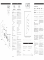
FIG. 04
Rotate the stopcocks (4.F) clockwise, using a
screwdriver. Unscrew the fixing screw (4.E),
using the wrench provided and remove the
test plug (4.D), pulling it outwards. Insert the
O-Ring seal (4.C) and sleeve (4.B) into the
thermostatic body. Use the special grease
provided to slightly lubricate the O-Ring seals
of the thermostatic cartridge (4.A). Insert the
cartridge into the faucet seat, making sure
to align the gap with the seat of the fixing
screw (4.E), and tighten the screw. Important!
Do not overtighten the screw (4.E). Excessive
torque could cause a malfunction or breakage.
The thermostatic cartridge is equipped with
a burn-prevention safety catch, which is set
to 100°F (38°C). Press the button on the
control handle to increase temperature. If hot
water or cold water pressure drops, the flow
is automatically stopped. Rotate the stopcocks
(4.F) anticlockwise, using a screwdriver.
FIG. 05
Fit the finish cap (5.A) to the embedded body.
Position the plate (5.B) on the thermostatic body,
until it is fully against the wall. Use silicone for
sealing the back part.
FIG. 06
Installation of control handles.
Proceed as follows to install the upper part of
the diverter cartridge:
Place the insert (6.M) on the cartridge rod and
secure it with the screw (6.L). Position the handle
(6.G) and secure with the grub screw (6.H).
Position the decorative plate (6.l) to complete
the installation.
Proceed as follows to install the lower part of
the thermostatic cartridge:
Screw the pin (6.E) on the thermostatic cartridge
rod, adding the shim (6.F), and install the
handle (6.A), placing the ring (6.D) in between,
without moving the rod to prevent compromising
cartridge calibration. Tighten with the relevant
grub screw (6.B) and position the decorative
plate (6.C).
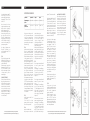
FIG. 07
Proceed as follows to replace the screw-down
valve handle (7.A):
Remove the plate (7.C), unscrew the fixing grub
screw (7.B) and pull out the handle (7.A).
Reassemble the new handle (7.A), secure it with
the grub screw (7.B) and insert the plate (7.C).
Proceed as follows to replace the thermostatic
handle (7.G):
Remove the plate (7.H), unscrew the fixing grub
screw (7.I) and pull out the handle (7.G).
Do not move the rod of the new cartridge (7.R)
to prevent compromising calibration.
Reassemble the new handle (7.G), secure it
with the grub screw (7.l) and insert the plate
(7.H).
Proceed as follows to replace the diverter or
thermostatic cartridge:
Remove the plate (7.C), unscrew the fixing grub
screw (7.B) and remove the handle (7.A).
Remove the plate (7.H), unscrew the fixing grub
screw (7.l) and remove the handle (7.G).
Pull out the plate (7.F) and rotate the stopcocks
(7.T) clockwise, using a screwdriver.
How to replace the diverter cartridge (7.V)
Remove the screw (7.D) and the fitting (7.E).
Use a wrench to unscrew the ring nut (7.U),
pull out the cartridge (7.V) and replace it, if
necessary. Ensure seal surfaces are clean and
reassemble following the procedure in reverse.
Close the ring nut (7.U) to ensure perfect seal
and smooth operation of the handle (7.A).

FIG. 04
FIG. 08
FIG. 05 FIG. 06
FIG. 07
English
Based on its policy of steady development Fortis reserves the right to change the characteristics
of the products without notice and therefore the images and data contained in this catalogue may vary.
Español
INSTRUCCIONES DE INSTALACIÓN
Alimentación Recomendada Máxima Mínima
Temperatura agua
caliente
65 C° (~150F) 80 C° (~175F) 15 C° (~60F)
Presión de
funcionamiento
3 BARES (~45PSI) 5 BARES (~75PSI) 0.5 BARES (~7PSI)
Español
How to replace the thermostatic cartridge (7.R)
Unscrew the fixing grub screw (7.S), then
extract the cartridge complete with accessories,
the temperature stop (7.O), the screw (7.P) and
the washer (7.Q)
Remove the accessories from the existing
cartridge and mount them on the new cartridge,
taking the white notch on the cartridge as
reference for the temperature stop (7.O).
Insert the new thermostatic cartridge (7.P) in the
faucet seat, making sure that the positioning
gap coincides with the seat of the fixing
grub screw (7.S), then tighten the grub screw
avoiding tightening too much. Excessive torque
could cause a malfunction or breakage. Do
not move the rod of the new cartridge (7.R) to
prevent compromising calibration.
Upon completion of replacement, unscrew
the stopcocks (7.T) anticlockwise, using a
screwdriver. Reassemble the plate (7.F) and
reposition the handles.
FIG. 08
The figure shows the faucet mounted correctly.
Rotate the handle (8.A) 90° clockwise or anti-
clockwise to regulate water flow; temperature is
controlled by the handle (8.B).
The thermostatic cartridge is equipped with a
burn-prevention safety catch, which is set to
38°C (100°F). Press the button on the control
handle to increase temperature. If hot water
or cold water pressure drops, the flow is
automatically stopped.
LOOKING AFTER THE SURFACE
The surface of the faucet should be cold during
cleaning (heat accelerates wear and tear on
the surface itself). Ensure cleaning products do
not contain acids or corrosive substances. The
faucet should be dried daily with a soft cloth.
Avoid using steel wool, abrasive sponges or
similar items. Immediately after cleaning rinse
detergent off with cold water. Damage to
faucets resulting from inappropriate treatment is
not covered by the warranty.
Por su política de continuo desarrollo, Fortis se reserva el derecho de modificar las características de los productos sin ningún aviso
previo; por tanto, las imágenes y los datos contenidos en el presente catálogo deben considerarse a título indicativo.
En caso de presiones de trabajo superiores a 5
bar (~75 psi) se recomienda utilizar un reductor
de presión. Antes de empezar el montaje,
se recomienda purgar las tuberías del agua
caliente y fría para evitar que la suciedad y
pequeñas impurezas puedan comprometer el
funcionamiento del grifo.
FIG. 04
Atornillar en sentido horario los grifos de parada
(4.F) usando un destornillador, destornillar
el tornillo de fijación (4.E) utilizando la llave
correspondiente, extraer el tapón de prueba
(4.D) tirando del mismo hacia el exterior. Insertar
en el cuerpo termostático el o-ring (4.C) y el
manguito (4.B). Utilizar una grasa especial en
dotación para lubricar ligeramente los o-rings
del cartucho termostático (4.A). Insertar en el
alojamiento correspondiente del grifo teniendo
cuidado de hacer coincidir el agujero de
colocación con el alojamiento del tornillo de
fijación (4.E), después atornillar este último.
¡Atención!, Evitar apretar con fuerza el tornillo
(4.E). Un cierre excesivo podría ocasionar
problemas de funcionamiento o roturas. El
cartucho termostático está dotado de protección
de seguridad anti quemadura regulado a
100°F (38°C) para obtener temperaturas más
elevadas es necesario apretar el pulsador
situado en la manilla de regulación. Si cesara
la presión del agua caliente o fría el caudal
se interrumpe inmediatamente. Destornillar en
sentido anti horario los grifos de parada (4.F)
con un destornillador.
FIG. 05
Atornillar la caperuza de acabado (5.A) al
cuerpo empotrado.
Colocar la placa (5.B) en el cuerpo
termostático, poniéndola a tope en la pared.
Sellar con silicona la parte de detrás.
FIG. 06
Instalación de las manillas de mando.
Para la parte superior con cartucho desviador
proceder de la manera siguiente:
colocar en la varilla del cartucho el separador
(6.M) y fijarlo con el tornillo correspondiente
(6.L). Colocar entonces la manilla (6.G)
y apretar con la espiga (6,H). Terminar
colocando la plaqueta de acabado (6.I).
Para la parte inferior con cartucho termostático
proceder de la manera siguiente:
atornillar el perno (6.E) en la varilla del cartucho
termostático añadiendo el calzo (6.F) e instalar
la manilla (6.A) intercalando el anillo (6.D),
sin mover la varilla, para evitar comprometer
el calibrado del cartucho mismo. Apretar con
la espiga de fijación correspondiente (6.B) y
colocar la plaqueta de acabado (6.C).
FIG. 07
En caso de sustitución unicamente de la manilla
de la rosca (7.A) proceder de la manera
siguiente:
extraer la plaqueta (7.C), destornillar la espiga
de sujeción (7.B) entonces extraer la manilla
(7.A). Montar de nuevo la manilla (7.A) y
fijarla con la espiga (7.B), terminar insertando
la plaqueta (7.C).
En caso de sustitución unicamente de la manilla
termostática (7.G) proceder de la manera
siguiente:
extraer la plaqueta (7.H), destornillar la espiga
de sujeción (7.I) entonces extraer la manilla
(7.G). Evitar absolutamente mover la varilla
del nuevo cartucho (7.R), para no perder el
calibrado. Montar de nuevo la manilla (7.G)
y fijarla con la espiga (7.I), terminar insertando
la plaqueta (7.H)
Para la sustitución del cartucho desviador o
termostático proceder de la manera siguiente:
Quitar la plaqueta (7.C), destornillar la espiga
de sujeción (7.B) entonces extraer la manilla
(7.A). Quitar la plaqueta (7.H), destornillar la
espiga de sujeción (7.I) entonces extraer la
manilla (7.G). Después de haber extraido la
placa (7.F) atornillar en sentido horario los grifos
de parada (7.T) utilizando un destornillador.
Para la sustitución del cartucho desviador (7.V)
Desmontar el tornillo (7.D) y el racor (7.E).
Con la ayuda de una llave destornillar la virola
(7.U), extraer el cartucho (7.V) y sustituirlo si
es necesario. Prestando atención especial a la
limpieza de las superficies donde actúan las
juntas de hermeticidad, montar de nuevo la
totalidad procediendo en el sentido inverso.
Cerrar la virola (7.U) para garantizar la
hermeticidad y al mismo tiempo permitir un
movimiento suave de la manilla (7.A).
Para la sustitución del cartucho termostático
(7.R) destornillar la espiga de sujeción (7.S),
entonces extraer el cartucho con los accesorios,
tope de temperatura (7.O) tornillo (7.P) y
arandela (7.Q). Desmontar los accesorios
del cartucho y volver a montarlos en el nuevo
cartucho, prestar atención a la muesca de
posicionamiento blanca en el cartucho como
referencia al tope de temperatura (7.O).
Insertar el nuevo cartucho termostático (7.R)
en el alojamiento correspondiente del grifo,
teniendo cuidado de hacer coincidir el
agujero de colocación con el alojamiento de
la espiga de fijación (7.S), después atornillar
este último evitando apretarlo con fuerza. Un
cierre excesivo podría ocasionar problemas de
funcionamiento o roturas. Evitar absolutamente
mover la varilla del nuevo cartucho (7.R), para
no perder el calibrado.
Terminada la sustitución destornillar en sentido
anti horario los grifos de parada (7.T) con un
destornillador. Volver a montar la placa (7.F), y
restablecer las manillas.
FIG. 08
La figura representa el grifo montado
correctamente. La apertura del agua se efectúa
girando la manilla (8.A) de 90° en sentido
horario o anti horario. La temperatura está
gestionada por la manilla (8.B).
El cartucho termostático está dotado de
protección de seguridad anti quemadura
regulado a 38°F (100°C) para obtener
temperaturas más elevadas es necesario apretar
el pulsador situado en la manilla de regulación.
Si cesara la presión del agua caliente o fría el
caudal se interrumpe inmediatamente.
MANTENIMIENTO DE LAS SUPERFICIES
Durante la limpieza, la superficie del grifo
debe estar fría (el calor acelera el deterioro
de la superficie misma). Comprobar que los
productos de limpieza no contienen ácidos o
sustancias corrosivas. El grifo debe secarse a
diario con un paño suave. Evitar absolutamente
estropajos, esponjas abrasivas o similares.
Justo después de la limpieza, aclarar bien los
residuos de detergente con agua fría. Los daños
a los grifos, consiguientes a un tratamiento
inapropiado, están excluidos de la garantía.
-
 1
1
-
 2
2


Fortis 9469100 Maintenance & Installation Instructions
- Categoría
- Artículos sanitarios
- Tipo
- Maintenance & Installation Instructions
Artículos relacionados
-
Fortis 92687l0 Maintenance & Installation Instructions
-
-
-
-
-
-
Fortis 92691l0 Maintenance & Installation Instructions
-
-
-