
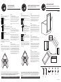
CONER SINK BASE CABINET
GABINETE DE BASE DE FREGADERO ESQUINADO
CBS36
7x 6x
8x 48x 88x 2x
ASSEMBLY INSTRUCTION / INSTRUCCIONES PARA LA INSTALLATION
06-2018 / PLAN-0402
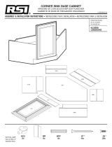
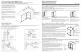
STEP 1:
CABINET INSTALLATION SELECT HARDWARE THAT
IS BEST SUITED FOR YOUR WALL TYPE*
STUDS:
Secure to wall with #10 x 3” screws
at stud location.
DRYWALL:
Drill holes and secure to the wall with
toogle bolts. Note: Use toggle bolts only
when cabinet must also be attached to
adjencent cabinet as outlined in Step 3.
CONCRETE:
Drill 1/4” holes, insert #10 wall anchors
and secure to wall with #10 x 3” screws.
IMPORTANT: USE "PAN HEAD" OR "ROUND HEAD"
SCREWS WITH SEAT WASHERS. SEAT SCREWS TIGHTLY
AGAINST BACK RAIL WITHOUT DRIVING INTO BACK RAIL
OR PANEL MATERIAL.
STEP 2:
COUNTERTOP CLEAT INSTALLATION- Locate and mark
all stud locations. Use 2x4 framing material as cleats to
support the countertop. Use a level to ensure the cleats are
level. Drill 3/16” pilot holes through the cleat and into the
stud. Mount the cleat to the wall with hardware appropriate
for your wall type.
STEP 3:
ATTACH CABINETS TOGETHER
Use C-clamps to align the adjacent cabinets to the Corner
Sink Cabinet. Use a level to ensure the cabinets are flush
and level with each other. Drill a 1/8” pilot hole in the face
frame above or below each door hinge location. Attach the
adjacent cabinets to the corner cabinet using #8 x 2-1/2”
screws and countersing for best apperance.
ATTENTION: You must drill pilot holes to attach cabinets
together.
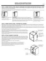
STEP 4:
MOUNT CABINETS TO THE WALL
Place all three cabinets into position in the corner. The
corner cabinet should be 36” from the wall both directions.
Use a level to ensure the cabinets are straight and level. If
needed, shim the cabinets to level.
IMPORTANT: Shim cabinets square (flat) to the wall so
there are no gaps between the back of the adjacent
cabinets and wall in mounting area. Drill a 3/16” pilot hole at
stud locations through the back rail of the adjacent
cabinets to the wall with hardware appropriate for your wall
type. Once your corner cabinets have been installed, work
outward to install the remaining cabinets.
STEP 5:
INSTALL REMAINING CABINETS
Drill a 3/16” pilot hole at the stud locations through the back
panel and into the stud. Level and mount the cabinet to the
wall with #10 x 3” screw. If needed, shim the cabinet to level.
DO NOT COMPLETELY TIGHTEN MOUNTING SCREWS
UNTIL ALL CABINETS HAVE BEEN ATTACHED TOGETHER.
After all cabinets have been attached together and are level
and secure, then tighten all mounting screws. Take care
to seat mounting screws tightly against back rail or panel
without driving into back rail or panel material. Check to be
sure that all cabinets remain after tightening.
CONER SINK BASE CABINET
INSTALLATION INSTRUCTION
36" 36"
Visit hamptonbaycabinetparts.com to order damaged or missing parts.
The fastening solution described here are recommendations only. and are based on commonly used installations. Each installer must
evaluate the specific characteristics of the particular wall on which the cabinets are to be installed to ensure the proper fastening solution is
used and the product is fastened safety and securely. This may require hardware or fastening methods which are different from, or
additional to, what is described here. FABRITEC DOES NOT WARRANT THE INSTALLATION OF THIS PRODUCT.
PASO 1:
INSTALACIÓN DEL GABINETE. SELECCIONA LOS
HERRAJES QUE MEJOR SE ADPTEN A TU TIPO DE PARED*
VIGAS:
FÍjalas a la pared con tornillos. NÚm.
10 x 7,62 cm en la ubicaciÓn de la vigas.
PANEL DE YESO:
Taladra orificios y asegura a la pared
con pernos acodados. Nota: Usa pernos
acodados sÓlo si el gabinete no se
puede fijar a la viga de pared. El
gabinete también debe asegurase a
otro gabinete adyacente, como lo
indica el Paso. 3.
CONCRETO:
Taladra orificis de 0,63 cm, inserta
anclajes de pared NÚm. 10 fija a la
pared con tornillos NÚm. 10 x 7,62 cm.
IMPORTANT: USE TORNILLOS DE "CABEZA PLANA
BISELADA" O "CABEZA REDONDA" CON ARANDELAS
DE ASIENTO. COLOCA LOS TORNILLOS FIRMEMENTE
CONTRA EL RIEL TRASERO SIN INSERTALOS EN EL
PANEL O EL RIEL
PASO 2:
INSTALACIÓN DEL SOPORTE DEL MOSTRADOR: Localiza
y marca la ubicaciÓn de todos los barrotes. Usa material de
enmarcar de 2x4 como tacos para sostener el mostrador.
Usa un nivel para asegurarte de que los tacos estén
nivelados. Taladra orificios piloto de 0,47 cm en el taco y
dentro del barrote. Monta el taco en la pared con las
herramientas apropriadas para tu tipo de pared.
PASO 3:
CONECTA LOS GABINETES ENTRE SÍ:
Usa abrazaderas en C para alinear los gabinetes adyacente
al Gabinete de Fregadero Esquinado. Usa un nivel para
garantizar que los gabinetes queden a ras y a nivel entre sÍ.
Taladra un orificio piloto de 1/8” en el marco frontal arriba y
debajo del lugar donde irán las bisagras de las puertas. Une
los gabinetes adyacentes al gabinete esquinado, usando
tornillos nÚm. 8 x 2-1/2” e instala al ras para darle un mejor
aspecto.
PASO 4:
MONTAR LOS GABINETES EN LA PARED:
Coloca en posiciÓn los tres gabinetes esquineros. El
gabinete de la esquina deberÍa estar a 91,44 cm de la pared
en ambos lados. Usa un nivel para asegurarte de que los
gabinetes estén rectos y nivelados. Si es necesario, usa cuña
para nivelar.
IMPORTANTE: Cuña los gabinetes en ángulo recto (plano)
a la pared de manera que no haya espacicios entre la parte
posterior de los gabinetes contiguos y la pared con las
herramientas apropiadas para tu tipo de pared. Una vez
instalados los gabinetes de las esquinas, trabaja hacia
afuera para instalar el resto de los gabinetes.
PASO 5:
INSTALAR EL RESTO DE LOS GABINETES:
Taladra un orifio piloto de 4,76 mm donde está la viga, a
través el reiles trasero y dentro de la misma. Nivela y monta
el gabinete a la pared con el tornillo NÚm. 10 x 7,62 cm. Si es
necesario usa cuñas para nivelar. NO APRIETES POR
COMPLETO LOS TORNILLOS DE MONTAJE HASTA QUE
LOS GABINETES ESTÉN UNIDOS. Aprieta todos los
gabinetes hasta que hayan sido unidos firmemente y estén a
nivel. AsegÚrate de que los tornillos de montaje descansen
firmemente contra el riel posterior sin que perforen el
material de ésto. Verifica que todos los gabinetes queden a
nivel después de apretados los tornillos.
”Las soluciones de sujeciÓn aquÍ descritas representa Únicamente recomendaciones y se basan en procedimientos tradicionales de
instalaciÓn. Cada instalador debe evaluar las caracterÍsticas especÍficas de la pared en particular donde se instalarán los gabinetes para
garantizar que se use la soluciÓn de sujeciÓn de sujeciÓn apropiada y que el producto quede fijo de manera segura. Ello podrÍa requerir
métodos o herrajes de sujecÓn distintos o adicionales a los acquÍ descritos. FABRITEC NO GARANTIZA LA INSTALACIÓN DE ESTE
PRODUCTO.”
GABINETE DE BASE DE FREGADERO ESQUINADO
INSTRUCCIONES DE INSTALACIÓN
36" 36"
Visit hamptonbaycabinetparts.com para realizar pedidos de pieza dañadas o faltantes.
90º
A B C D E F
135º
2
3
6
7
8
1
4
5

1/8"
1/8"
1/8"
1/8"
1/8"
1.
2.
5.
3.
Install the metal brackets as it is indicated on the drawing below. Each screw must have two washers
before being screwed.
Instale el metal de los soportes como se indica en el dibujo abajo. Cada tornillo debe tener dos
arandelas antes de ser atornillados.
Using dowels, assemble panels
2 and 3 together. Same goes for
panels 5 and 6.
Mediante pasadores, Monte los
paneles 2 y 3 juntos. Lo mismo va
para paneles de 5 y 6.
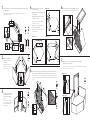
Lay the cabinet on its back. Using screws, install the toe kick (piece 7) and secure all the panel together.
Each screw must have two washers before being screwed. Insert the F cams in the holes under panel 1.
Coloque el gabinete en su parte posterior. Utilizando los tornillos, instalar el rodapié (pieza 7) y fije el panel
juntos. Cada tornillo debe tener dos arandelas antes de ser atornillados. Insertar las levas F en los orificios en
el panel 1.
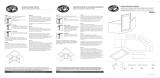
Using the metal brackets, screw the
panels together. Each screw must
have two washers before being
screwed.
Utilizando los soportes de metal,
atornillar los paneles. Cada tornillo
debe tener dos arandelas antes de
ser atornillados.
52x26x
STEP 4.1 / PASO 4.1
STEP 4.2 / PASO 4.2 STEP 4.3 / PASO 4.3
4x
4x
8x
14x
28x
2x
6x7x
4.
4.1 Using dowels, insert panel 1 into the slot of the
corner made of panels 2 & 3.
4.2 Slide panel 1 into the slot of panel 4 and push hard
for a good steadiness.
4.3 Using dowels, insert panel 1 into the slot of the
corner made of panels 5 & 6.
4.1 Con tacos, inserte el panel 1 en la ranura de la
esquina de los paneles 2 y 3.
4.2 Deslice panel 1 en la ranura del panel 4 y empuje
duro para una buena estabilidad.
4.3 Con tacos, inserte el panel 1 en la ranura de la
esquina de paneles 5 y 6.
6.
7.
Install the door frame 8 onto bottom panel and tighten the F cams.
Instale el marco de la puerta 8 en panel inferior y apriete las levas F .
7.1 Pre-drill a hole of 1/8” deep in the frame (drill bit size: 5/64’’ diameter (#47).
7.2 Using screws, secure the door frame.
7.1 Pre-taladrar un agujero de 1/8» en el marco (tamaño de broca de taladro: 5/64 ‘’ diámetro (#47).
7.2 Con tornillos, fije el marco de la puerta.
4x
90º 135º
2x
2x
STEP 7.1 / PASO 7.1
STEP 7.2 / PASO 7.2
A
A
D E
C
C
C
D
D
F
E
E
B
A
B
A
A
B
B
B
A
B
B
A
A
D 1X
E 2X
D 1X
E 2X
D 1X
D 1X
E 2X
E 2X
D
A
A
3
4
5
6
1
1
1
1
2
2
2
6
3
3
3
5
4
7
1
8
4
2
2 6
3
3
5
62
5
F
F
-
 1
1
-
 2
2


Hampton Bay CBS36-MWW Instrucciones de operación
- Tipo
- Instrucciones de operación
- Este manual también es adecuado para
en otros idiomas
Artículos relacionados
-
 Hampton Bay CBS36-PWW Instrucciones de operación
-
 Hampton Bay KCSB36-SJM Instrucciones de operación
-
Hampton Bay B21-PJAV Guía de instalación
-
-
 Hampton Bay CBS36-MMO Instrucciones de operación
-
 Hampton Bay KBLS36-MO Guía de instalación
-
Hampton Bay KW3618-UF Guía de instalación
-
 Hampton Bay KSBF60-UF Instrucciones de operación
-
 Hampton Bay KW3624-SW Guía de instalación


