Yamaha YST-SW515 El manual del propietario
- Tipo
- El manual del propietario

YST-SW515
Subwoofer System
RTL
OWNER’S MANUAL
MANUAL DE INSTRUCCIONES
YST-SW515_RTL.book Page 1 Thursday, August 5, 2004 9:37 AM

Thank you for selecting this YAMAHA subwoofer system.
Please read the following operating precautions
before use. YAMAHA will not be held responsible
for any damage and/or injury caused by not
following the cautions below.
• To assure the finest performance, please read this
manual carefully. Keep it in a safe place for future
reference.
• Install this unit in a cool, dry, clean place - away from
windows, heat sources, sources of excessive vibration,
dust, moisture and cold. Avoid sources of humming
(transformers, motors). To prevent fire or electrical
shock, do not expose this unit to rain or water.
• Never open the cabinet. If something drops into the set,
contact your dealer.
• The voltage to be used must be the same as that specified
on the rear panel. Using this unit with a higher voltage
than specified is dangerous and may cause a fire and/or
electric shock.
• To reduce the risk or fire or electric shock, do not expose
this unit to rain or moisture.
• Do not use force on switches, controls or connection
wires. When moving the unit, first disconnect the power
plug and the wires connected to other equipments.
Never pull the wires themselves.
• When not planning to use this unit for a long period (ie.,
vacation, etc.), disconnect the AC power plug from the
wall outlet.
• To prevent lightning damage, disconnect the AC power
plug when there is an electric storm.
• Since this unit has a built-in power amplifier, heat will
radiate from the rear panel. Place the unit apart from the
walls, allowing at least 20 cm of space above, behind and
on both sides of the unit to prevent fire or damage.
Furthermore, do not position with the rear panel facing
down on the floor or other surfaces.
• Do not cover the rear panel of this unit with a newspaper,
a tablecloth, a curtain, etc. in order not to obstruct heat
radiation. If the temperature inside the unit rises, it may
cause fire, damage to the unit and/or personal injury.
• Do not place the following objects on this unit:
Glass, china, small metallic etc.
If glass etc. falls by vibrations and breaks, it may cause
bodily injury.
A burning candle etc.
If the candle falls by vibrations, it may cause fire and
bodily injury.
A vessel with water in it
If the vessel falls by vibrations and water spills, it may
cause damage to the speaker, and/or you may get an
electric shock.
• Do not place this unit where foreign objects such as
water drips might fall. It might cause a fire, damage to
this unit, and/or personal injury.
• Never put a hand or a foreign object into the YST port
located on the right side of this unit. When moving this
unit, do not hold the port as it might cause personal
injury and/or damage to this unit.
• Never place a fragile object near the YST port of this
unit. If the object falls or drops by the air pressure, it may
cause damage to the unit and/or personal injury.
• Never open the cabinet. It might cause an electric shock
since this unit uses a high voltage. It might also cause
personal injury and/or damage to this unit.
• When using a humidifier, be sure to avoid condensation
inside this unit by allowing enough spaces around this
unit or avoiding excess humidification. Condensation
might cause a fire, damage to this unit, and/or electric
shock.
• Super-bass frequencies reproduced by this unit may
cause a turntable to generate a howling sound. In such a
case, move this unit away from the turntable.
• This unit may be damaged if certain sounds are
continuously outputted at high volume level. For
example, if 20 Hz-50 Hz sine waves from a test disc,
bass sounds from electronic instruments, etc. are
continuously outputted, or when the stylus of a turntable
touches the surface of a disc, reduce the volume level to
prevent this unit from being damaged.
• If you hear distorted noise (i.e., unnatural, intermittent
“rapping” or “hammering” sounds) coming from this
unit, reduce the volume level. Extremely loud playing of
a movie soundtrack’s low frequency, bass-heavy sounds
or similarly loud popular music passages can damage
this speaker system.
• Vibration generated by super-bass frequencies may
distort images on a TV. In such a case, move this unit
away from the TV set.
• Do not attempt to clean this unit with chemical solvents
as this might damage the finish. Use a clean, dry cloth.
• Be sure to read the “TROUBLESHOOTING” section
regarding common operating errors before concluding
that the unit is faulty.
• Secure placement or installation is the owner’s
responsibility. YAMAHA shall not be liable for any
accident caused by improper placement or
installation of speakers.
CAUTION: Read this before operating your unit
YST-SW515_RTL.book Page i Thursday, August 5, 2004 9:37 AM

1
English
• VOLTAGE SELECTOR
(China, Korea, Asia and General models only)
The voltage selector switch on the rear panel of this
unit must be set for your local main voltage BEFORE
plugging this unit into the AC main supply. Voltages
are 110/120/220/230-240 V AC, 50/60 Hz.
For U.K. customers
If the socket outlets in the home are not suitable for the
plug supplied with this appliance, it should be cut off and
an appropriate 3 pin plug fitted. For details, refer to the
instructions described below.
Note: The plug severed from the mains lead must be
destroyed, as a plug with bared flexible cord is hazardous
if engaged in a live socket outlet.
SPECIAL INSTRUCTIONS FOR U.K. MODEL
FEATURES ....................................................................2
SUPPLIED ACCESSORIES ...........................................2
PLACEMENT ................................................................3
CONNECTIONS ........................................................... 4
Connecting to line output (pin jack) terminals
of the amplifier .................................................... 4
Connecting to speaker output terminals of
the amplifier .......................................................... 6
Connecting to the INPUT1/ OUTPUT terminals
of the subwoofer .........................................................8
Plug in the subwoofer to the AC outlet ......................8
CONTROLS AND THEIR FUNCTIONS .................... 9
AUTOMATIC POWER-SWITCHING
FUNCTION ................................................................. 11
Changing the AUTO STANDBY setting .................11
ADJUSTING THE SUBWOOFER
BEFORE USE ............................................................. 12
Frequency characteristics .........................................13
ADVANCED YAMAHA ACTIVE SERVO
TECHNOLOGY II ....................................................... 14
TROUBLESHOOTING ............................................... 15
SPECIFICATIONS ...................................................... 16
Standby mode
When this unit is set in standby mode by pressing the
STANDBY/ON button on the control panel, this unit
consumes a small amount of power. This state is called
the standby mode. This unit’s power supply is
completely cut off from the AC line only when the
POWER switch on the rear panel is set in the OFF
position or the AC power cord is disconnected.
This unit features a magnetically shielded design, but
there is still a chance that placing it too close to a TV
set might impair picture color. Should this happen,
move this unit away from the TV set.
IMPORTANT:
THE WIRES IN MAINS LEAD ARE COLOURED
IN ACCORDANCE WITH THE FOLLOWING
CODE:
Blue: NEUTRAL
Brown: LIVE
As the colours of the wires in the mains lead of this
apparatus may not correspond with the coloured
markings identifying the terminals in your plug,
proceed as follows: The wire which is coloured
BLUE must be connected to the terminal which is
marked with the letter N or coloured BLACK. The
wire which is coloured BROWN must be connected
to the terminal which is marked with the letter L or
coloured RED. Making sure that neither core is
connected to the earth terminal of the three pin plug.
For Canadian Customers
To prevent electric shock, match wide blade of plug
to wide slot and fully insert.
This Class B digital apparatus complies with
Canadian ICES-003.
CONTENTS
1
2
YST-SW515_RTL.book Page 1 Thursday, August 5, 2004 9:37 AM

2
• This subwoofer system employs Advanced Yamaha
Active Servo Technology II which Yamaha has
developed for reproducing higher quality super-bass
sound. (Refer to page 14 for details on Advanced
Yamaha Active Servo Technology II.) This super-bass
sound adds a more realistic, theater-in-the-home effect
to your stereo system.
• This subwoofer can be easily added to your existing
audio system by connecting to either the speaker
terminals or the line output (pin jack) terminals of the
amplifier.
• For the effective use of the subwoofer, the subwoofer’s
super-bass sound should be matched to the sounds of
your front speakers. You can create the best sound
quality for various listening conditions by using the
HIGH CUT control and the PHASE switch.
• The Automatic power-switching function saves you the
trouble of pressing the STANDBY/ON button to turn the
power on and off.
• You can select bass effect suitable for the source by
using the B.A.S.S. button.
• This subwoofer system is equipped with a linear port
unique to Yamaha that provides smooth bass response
during playback, minimizing extraneous noise not
included in the original input signal.
After unpacking, check that the following parts are
contained.
Non-skid pads
FEATURES
QD-Bass Technology
QD-Bass (Quatre Dispersion Bass) technology is a
Yamaha unique technology to radiate the sound
efficiently in four horizontal direction.
SUPPLIED ACCESSORIES
YST-SW515_RTL.book Page 2 Thursday, August 5, 2004 9:37 AM

3
English
( : subwoofer, : front speaker)
One subwoofer will have a good effect on your audio
system, however, the use of two subwoofers is
recommended to obtain more effect.
If using one subwoofer, it is recommended to place it on
the outside of either the right or the left front speaker. (See
fig. .) If using two subwoofers, it is recommended to
place them on the outside of each front speaker. (See
fig. .) The placement shown in fig. is also possible,
however, if the subwoofer system is placed directly facing
the wall, the bass effect may die because the sound from it
and the sound reflected by the wall may cancel out each
other. To prevent this from happening, face the subwoofer
system at an angle as in fig. or .
Note
There may be a case that you cannot obtain enough super-
bass sounds from the subwoofer when listening in the
center of the room. This is because “standing waves” have
been developed between two parallel walls and they cancel
the bass sounds.
In such a case, face the subwoofer obliquely to the wall. It
also may be necessary to break up the parallel surfaces by
placing bookshelves etc. along the walls.
Use the non-skid pads
Put the provided non-skid pads at the four corners on the
bottom of the subwoofer to prevent the subwoofer from
moving by vibrations etc.
PLACEMENT
A
B
C
A
B C
A
B
YST-SW515_RTL.book Page 3 Thursday, August 5, 2004 9:37 AM

4
Choose one of the following two connecting methods that is more suitable for your audio system.
■ Choose (pages 4-5) if your amplifier has line output (pin jack) terminal(s)
■ Choose (pages 6-7) if your amplifier has no line output (pin jack) terminal
Caution: Unplug the subwoofer and other audio/video components before making
connections.
Notes
• All connections must be correct, that is to say L (left) to L, R (right) to R, “+” to “+” and “–” to “–”. Also, refer to the
owner’s manual of your component to be connected to the subwoofer.
• After all connections are completed, plug in the subwoofer and other audio/video components.
• To connect with an amplifier (or AV receiver), connect the SUBWOOFER (or LOW PASS etc.) terminal on the rear of
the amplifier (or AV receiver) to the /MONO INPUT2 terminal of the subwoofer.
• When connecting the subwoofer to the SPLIT SUBWOOFER terminals on the rear of the amplifier, be sure to connect
the /MONO INPUT2 terminal to the “L” side and the INPUT2 terminal to the “R” side of the SPLIT
SUBWOOFER terminals.
Notes
• Some amplifiers have line output terminals labeled PRE OUT. When you connect the subwoofer to the PRE OUT
terminals of the amplifier, make sure that the amplifier has at least two sets of PRE OUT terminals. If the amplifier has
only one set of PRE OUT terminals, do not connect the subwoofer to the PRE OUT terminals. Instead, connect the
subwoofer to the speaker output terminals of the amplifier. (Refer to pages 6-7.)
• When connecting to a monaural line output terminal of the amplifier, connect the /MONO INPUT2 terminal.
• When connecting to line output terminals of the amplifier, other speakers should not be connected to the OUTPUT
terminals on the rear panel of the subwoofer. If connected, they will not produce sound.
CONNECTIONS
1
2
Connecting to line output (pin jack) terminals of the amplifier
1
L
L
R
L
YST-SW515_RTL.book Page 4 Thursday, August 5, 2004 9:37 AM

5
CONNECTIONS
English
■ Using one subwoofer
■ Using two subwoofers
Subwoofer
Amplifier
To AC outlet
Mono pin cable
(not included)
Audio pin cable
(not included)
Amplifier
To AC outlet
To AC outlet
Mono pin cable(not included)
Mono pin cable
(not included)
Subwoofer Subwoofer
YST-SW515_RTL.book Page 5 Thursday, August 5, 2004 9:37 AM

6
CONNECTIONS
Select this method if your amplifier has no line output (pin jack) terminal.
If your amplifier has two sets of front speaker output terminals and both terminals can
output sound signals simultaneously.
• Connect one set of front speaker output terminals of the amplifier to the INPUT1 terminals of the subwoofer, and
connect the other set of front speaker output terminals of the amplifier to the front speakers.
• Set the amplifier so that both sets of front speaker output terminals output sound signals simultaneously.
Note
• If your amplifier has only one set of front speaker output terminals, see page 7.
■ Using one subwoofer (with speaker cables)
■ Using two subwoofers (with speaker cables)
Connecting to speaker output terminals of the amplifier
2
Right front speaker Subwoofer
To AC outlet
Left front speaker
Amplifier
Speaker
output
terminals
Amplifier
Right front speaker
Left front speaker
Subwoofer
To AC outlet
To AC outlet
Subwoofer
Speaker
output
terminals
YST-SW515_RTL.book Page 6 Thursday, August 5, 2004 9:37 AM

7
CONNECTIONS
English
If your amplifier has only one set of front speaker output terminals.
Connect the speaker output terminals of the amplifier to the INPUT1 terminals of the subwoofer, and connect the
OUTPUT terminals of the subwoofer to the front speakers.
■ Using one subwoofer (with speaker cables)
■ Using two subwoofers (with speaker cables)
Right front speaker
Left front speaker
Subwoofer
Amplifier
Speaker output
terminals
To AC outlet
Right front speaker Left front speaker
Subwoofer
Speaker output
terminals
To AC outlet To AC outlet
Amplifier
Subwoofer
YST-SW515_RTL.book Page 7 Thursday, August 5, 2004 9:37 AM

8
CONNECTIONS
For connection, keep the speaker cables as short as
possible. Do not bundle or roll up the excess part of the
cables. If the connections are faulty, no sound will be heard
from the subwoofer or the speakers, or both of them. Make
sure that the + and – polarity markings of the speaker
cables are observed and set correctly. If these cables are
reversed, the sound will be unnatural and lack bass.
Caution
Do not let the bare speaker wires touch each other, because
this could damage the subwoofer or the amplifier, or both of
them.
■ Before connecting
Remove the insulation coating at the extremity of each
speaker cable by twisting the coating off.
■ How to connect:
1 Loosen the terminal’s knob, as shown in the figure.
2 Insert the bare wire.
3 Tighten the knob.
4 Test the firmness of the connection by pulling lightly
on the cable at the terminal.
U.S.A., Canada and Australia models only
Banana Plug conection are also possible.
1 Tighten the terminal knob.
2 Simply insert the banana plug into the terminal
After all connections are completed, plug in the subwoofer
and other audio/video components to the AC outlet.
Connecting to the INPUT1/OUTPUT
terminals of the subwoofer
Good No Good
10mm
(3/8”)
2
1
3
Red: positive (+)
Black: negative (
–)
Plug in the subwoofer to the AC outlet
2
1
To AC outlet
YST-SW515_RTL.book Page 8 Thursday, August 5, 2004 9:37 AM

9
English
1 Power indicator
Lights up in green while the subwoofer is on.
Lights up in red while the subwoofer is set in the
standby mode by the operation of the automatic power-
switching function.
Goes off when the subwoofer is set in the standby
mode.
2 STANDBY/ON button
Press this button to turn on the power when the
POWER switch is set in the ON position. (The power
indicator lights up in green.)
Press again to set the subwoofer in the standby mode.
(The power indicator goes off.)
3 B.A.S.S. (Bass Action Selector System) button
When this button is pressed in to the MUSIC position,
the bass sound in audio software is well reproduced.
By pressing the button again so that it pops out at the
MOVIE position, the bass sound in video software is
well reproduced.
4 HIGH CUT control
Adjusts the high frequency cut off point.
Frequencies higher than the frequency selected by this
control are all cut off (and no output).
* One graduation of this control represents 10 Hz.
5 VOLUME control
Adjusts the volume level. Turn the control clockwise to
increase the volume, and counterclockwise to decrease
the volume.
6 VOLTAGE SELECTOR switch
(China, Korea, Asia and General models only)
If the preset setting of the switch is incorrect, set the
switch to the proper voltage (110V, 120V, 220V or
230-240V) of your area.
Consult your dealer if you are unsure of the correct
setting.
WARNING
Be sure to unplug the subwoofer before setting the
VOLTAGE SELECTOR switch correctly.
7 POWER switch
Normally, set this switch to the ON position to use the
subwoofer. In this state, you can turn on the subwoofer
or turn the subwoofer into the standby mode by
pressing the STANDBY/ON button. Set this switch to
the OFF position to completely cut off the subwoofer’s
power supply from the AC line.
CONTROLS AND THEIR FUNCTIONS
Rear panel
(General model)
Front panel
Standby mode
The subwoofer is still using a small amount of
power in this mode.
YST-SW515_RTL.book Page 9 Thursday, August 5, 2004 9:37 AM

10
CONTROLS AND THEIR FUNCTIONS
8 OUTPUT (TO SPEAKERS) terminals
Can be used for connecting to the main speakers.
Signals from the INPUT1 terminals are sent to these
terminals.
(Refer to “CONNECTIONS” for details.)
9 INPUT1 (FROM AMPLIFIER) terminals
Used to connect the subwoofer with the speaker
terminals of the amplifier.
(Refer to “CONNECTIONS” for details.
0 INPUT2 terminals
Used to input line level signals from the amplifier.
(Refer to “CONNECTIONS” for details.)
A AUTO STANDBY (HIGH/LOW/OFF) switch
This switch is originally set to the OFF position. By
setting this switch to the HIGH or LOW position, the
subwoofer’s automatic power-switching function
operates as described on page 11. If you do not need
this function, leave this switch in the OFF position.
* Make sure to change the setting of this switch only
when the subwoofer is set in the standby mode by
pressing the STANDBY/ON button.
B PHASE switch
Normally this switch is to be set to the REV (reverse)
position. However, according to your speaker systems
or the listening condition, there may be a case when
better sound quality is obtained by setting this switch
to the NORM (normal) position. Select the better
position by monitoring the sound.
YST-SW515_RTL.book Page 10 Thursday, August 5, 2004 9:37 AM

11
English
This function automatically switches the unit between standby and power-on modes.
The subwoofer automatically places itself in standby mode if it does not receive an input signal for 7 or 8 minutes. (The
power indicator lights red.)
When the subwoofer detects a bass signal input of below 200 Hz, it automatically places itself in power-on mode. (The
power indicator lights green.)
1 Set the subwoofer to standby.
2 Change the AUTO STANDBY setting.
- LOW: Normally select this position to activate this function.
- HIGH: If this function does not operate with AUTO STANDBY switch set to LOW, select this position so that the
subwoofer detects input signals with a lower level and switches the power on automatically.
- OFF: Select this position to deactivate this function, for example, when the subwoofer switches the power on
unexpectedly by sensing noises from other appliances.
Notes:
• This function does not operate when the POWER switch is set to the OFF position, or when you manually set the
subwoofer to standby mode by pressing the STANDBY/ON button.
• Noise received from other appliances may extend the time period before the subwoofer places itself in standby mode to
more than 8 minutes.
AUTOMATIC POWER-SWITCHING FUNCTION
Changing the AUTO STANDBY setting
YST-SW515_RTL.book Page 11 Thursday, August 5, 2004 9:37 AM

12
Before using the subwoofer, adjust the subwoofer to obtain the optimum volume and tone balance between the subwoofer
and the front speakers by following the procedures described below.
1 Set the VOLUME control to minimum (0).
2 Turn on the power of all the other components.
3 Make sure that the POWER switch is set to the ON
position, then press the STANDBY/ON button to turn
on the subwoofer.
* The Power indicator lights up in green.
4 Play a source containing low-frequency components
and adjust the amplifier’s volume control to the desired
listening level.
5 Adjust the HIGH CUT control to the position where
the desired response can be obtained.
Normally, set the control to the level a little higher than
the front speaker’s rated minimum reproducible
frequency*.
* The front speaker’s rated minimum reproducible
frequency can be looked up in the speakers’ catalog
or owner’s manual.
6 Increase the volume gradually to adjust the volume
balance between the subwoofer and the front speakers.
Normally, set the control to the level where you can
obtain a little more bass effect than when the
subwoofer is not used. If the desired response cannot
be obtained, adjust the HIGH CUT control and the
VOLUME control again.
7 Set the PHASE switch to the position which gives you
the better bass sound.
Normally, set the switch to the REV (reverse) position.
If the desired response cannot be obtained, set the
switch to the NORM (normal) position.
8 Select “MOVIE” or “MUSIC” according to the played
source.
MOVIE:
When a movie type source is played, the low-
frequency effects are enhanced to allow the listeners
enjoy more powerful sound. (The sound will be thicker
and deeper.)
MUSIC:
When an ordinary music source is played, the
excessive low-frequency components are cut off to
make the sound clearer. (The sound will be lighter and
reproduces the melody line more clearly.)
• Once the volume balance between the subwoofer and
the front speakers is adjusted, you can adjust the
volume of your whole sound system by using the
amplifier’s volume control.
However, if you change the front speakers to others,
you must make this adjustment again.
• For adjusting the VOLUME control, the HIGH CUT
control and the PHASE switch, refer to “Frequency
characteristics” on page 13.
ADJUSTING THE SUBWOOFER BEFORE USE
3 8 5 1,6 3 7
YST-SW515_RTL.book Page 12 Thursday, August 5, 2004 9:37 AM

13
ADJUSTING THE SUBWOOFER BEFORE USE
English
This subwoofer’s frequency characteristics
The figures below show the optimum adjustment of each control and the frequency characteristics when this subwoofer
is combined with a typical front speaker system.
■ EX.1 When combined with a 4” or 5” (10 cm or 13 cm) acoustic suspension, 2 way system front
speakers
■ EX.2 When combined with an 8” or 10” (20 cm or 25 cm) acoustic suspension, 2 way system front
speakers
*This diagram does not depict actual frequency response characteristics accurately.
Frequency characteristics
(70Hz) (REV)
(50Hz) (REV)
20 50 100 200 500Hz
40
50
60
70
80
90
dB
HIGH CUT 40 Hz
HIGH CUT 90 Hz
HIGH CUT 140 Hz
PHASE
REVNORM
20 50 100 200 500Hz
40
50
60
70
80
90
dB
YST-SW515
Front
speaker
Frequency response graph*
PHASE
REVNORM
20 50 100 200 500Hz
40
50
60
70
80
90
dB
YST-SW515
Front
speaker
Frequency response graph*
YST-SW515_RTL.book Page 13 Thursday, August 5, 2004 9:37 AM

14
In 1988, Yamaha brought to the marketplace speaker
systems utilizing YST (Yamaha Active Servo Technology)
to give powerful, high quality bass reproduction. This
technique uses a direct connection between the amplifier
and speaker, allowing accurate signal transmission and
precise speaker control.
As this technology uses speaker units controlled by the
negative impedance drive of the amplifier and resonance
generated between the speaker cabinet volume and port, it
creates more resonant energy ( the “air woofer” concept)
than the standard bass reflex method. This allows for bass
reproduction from much smaller cabinets than was
previously possible.
Yamaha’s newly developed Advanced YST II adds many
refinements to Yamaha Active Servo Technology,
allowing better control of the forces driving the amplifier
and speaker. From the amplifier’s point of view, the
speaker impedance changes depending on the sound
frequency. Yamaha developed a new circuit design
combining negative-impedance and constant-current
drives, which provides a more stable performance and
clear bass reproduction without any murkiness.
ADVANCED YAMAHA ACTIVE SERVO TECHNOLOGY II
High-amplitude
bass sound
Port
Cabinet
Advanced impedance
Converter
Active
Servo
Processing
Amplifier
Signals of low amplitude
Air woofer
(Helmholtz resonator)
Signals
YST-SW515_RTL.book Page 14 Thursday, August 5, 2004 9:37 AM

15
English
Refer to the chart below when this unit does not function properly. If the problem you are experiencing is not listed below
or if the instructions given below do not help, disconnect the power cord and contact your authorized YAMAHA dealer
or service center.
TROUBLESHOOTING
Problem Cause What to Do
Power is not supplied even though the
STANDBY/ON button is set to the ON
position.
The power plug is not securely
connected.
Connect it securely.
The POWER switch is set to the OFF
position.
Set the POWER switch to the ON
position.
No sound. The volume is set to minimum. Raise the volume up.
Speaker cables are not connected
securely.
Connect them securely.
Sound level is too low. Speaker cables are not connected
correctly.
Connect them correctly, that is L (left) to
L, R (right) to R, “+” to “+” and
“–” to “–”.
Setting of the PHASE switch is not
proper.
Set the PHASE switch to the other
position.
A source sound with few bass
frequencies is played.
Play a source sound with bass
frequencies.
Set the HIGH CUT control to a higher
position.
It is influenced by standing waves. Reposition the subwoofer or break up
the parallel surface by placing
bookshelves etc. along the walls.
The subwoofer does not turn on
automatically.
The POWER switch is set to the OFF
position.
Set the POWER switch to the ON
position.
The STANDBY/ON button is set to the
STANDBY position.
Set the STANDBY/ON button to the ON
position.
The AUTO STANDBY switch is set to
the OFF position.
Set the AUTO STANDBY switch to the
“HIGH” or “LOW” position.
The level of input signal is too low. Set the AUTO STANDBY switch to the
“HIGH” position.
The subwoofer does not turn into the
standby mode automatically.
There is an influence of noise generated
from external appliances etc.
Move the subwoofer farther away from
such appliances and/or reposition the
connected speaker cables.
Otherwise, set the AUTO STANDBY
switch to the “OFF” position.
The AUTO STANDBY switch is set to
the OFF position.
Set the AUTO STANDBY switch to the
“HIGH” or “LOW” position.
The subwoofer turns into the standby
mode unexpectedly.
The level of input signal is too low. Set the AUTO STANDBY switch to the
“HIGH” position.
The subwoofer turns on unexpectedly. There is an influence of noise generated
from external appliances etc.
Move the subwoofer farther away from
such appliances and/or reposition the
connected speaker cables.
Otherwise, set the AUTO STANDBY
switch to the “OFF” position.
YST-SW515_RTL.book Page 15 Thursday, August 5, 2004 9:37 AM

16
Type.......... Advanced Yamaha Active Servo Technology
Driver ........................................25 cm (10”) cone woofer
Magnetic shielding type
Amplifier Output (100 Hz, 5 ohms, 10% THD)
................................................................................250 W
Frequency Response ............................... 20 Hz - 160 Hz
Power Supply
USA and Canada models...................AC 120V, 60 Hz
U.K. and Europe models....................AC 230V, 50 Hz
Australia model..................................AC 240V, 50 Hz
China, Korea, Asia and General models
........................AC 110/120/220/230-240 V, 50/60 Hz
Power Consumption................................................80 W
Standby Power Consumption ...............................0.5 W
Dimensions (W x H x D)
........................................350mm x 430 mm x 382 mm
(13-3/4” x 16-15/16” x 15-1/16”)
Weight ............................................ 19 kg (41 lbs. 13 oz.)
Please note that all specifications are subject to change
without notice.
SPECIFICATIONS
YST-SW515_RTL.book Page 16 Thursday, August 5, 2004 9:37 AM

Gracias por haber seleccionado un sistema de altavoces de ultragraves YAMAHA.
Lea las siguientes precauciones de funcionamiento antes
de iniciar el uso del aparato. YAMAHA no se
responsabilizará de cualquier daño y/o lesión causada por
no seguir las precauciones que aparecen a continuación.
• Lea cuidadosamente este manual para obtener el mejor
rendimiento posible. Manténgalo en un lugar seguro
para utilizarlo como referencia en el futuro.
•I
nstale esta unidad en un lugar fresco, seco y limpio, alejado
de las ventanas, aparatos que produzcan calor, lugares con
muchas vibraciones, polvo, humedad y frío. Evite aparatos
que causen ruidos de zumbido (transformadores y motores).
Para evitar incendios o descargas eléctricas, no exponga la
unidad a la lluvia o al agua.
• No abrá nunca la carcasa. Si algo cae en el equipo,
póngase en contacto con su distribuidor.
• El voltaje a utilizar debe de ser el mismo que el
especificado en el panel trasero. La utilización de esta
unidad con un voltaje superior al especificado puede
causar un incendio y/o un a descarga eléctrica.
• Para reducir el riesgo de incendio y descarga eléctrica,
no exponga esta unidad a la lluvia o a la humedad.
• No fuerce los interruptores, controles o cables de
conexión. Cuando mueva esta unidad, desconecte
primero el cable de alimentación y los cables conectados
a otros equipos. No tire nunca de los cables en sí.
• Cuando no se va a usar el aparato por un largo tiempo (ej.
vacaciones, etc.) desconecte el enchufe de alimentación
de CA del tomacorriente.
• Para evitar daños debidos a relámpagos, desenchufe el
cable de la alimentación de CA durante tormentas
eléctricas.
• Este sistema irradia calor por el panel trasero debido a
que tiene un amplificador de potencia incorporado.
Coloque la unidad separada de las paredes, dejando unos
20 cm de espacio sobre, detrás y a ambos lados de la
unidad para evitar un incendio o cualquier otro tipo de
daño. Tampoco, se debe colocar con el panel trasero
contra el piso o apoyado sobre otras superficies.
• No cubra el panel trasero de la unidad con papel de
periódico, un mantel, una cortina, etc. para no obstruir la
radiación de calor. Si aumenta la temperatura en el
interior de la unidad, podrían originarse un incendio,
daños a la unidad y/o lesiones personales.
• No coloque los siguientes objetos sobre esta unidad:
Vidrio, porcelanana, pequeños trozos de metal etc.
Si el vidrio, etc. se cae debido a las vibraciones y se
romple, podría causar lesiones personales.
Un candelabro encendido, etc.
Si el candelabro cae debido a las vibraciones, podría
provocar un incendio y lesiones personales.
Un jarrón con agua en su interior
Si el jarrón cae debido a las vibraciones y el agua se
derrama, podría causar daños en el altavoz, y/o una
descarga eléctrica.
• No coloque esta unidad donde puedan caer objetos
extraños, como agua derramada. Podría provocar un
incendio, daños a esta unidad y/o daños personales.
• Nunca ponga las manos o un objeto extraño en el puerto
YST, situado a la derecha de esta unidad. Al mover esta
unidad, no sujete el puerto, ya que podría provocar
lesiones personales y/o daños a esta unidad.
• Nunca coloque un objeto frágil cerca del puerto YST de
esta unidad. Si el objeto cae o se vuelca debido a la
presión del aire, podría provocar lesiones en la unidad y/
o lesiones personales.
• No abrá nunca la carcasa. Podría provocar una descarga
eléctrica, ya que esta unidad necesita una tensión alta.
También podría provocar lesiones personales y/o daños
a esta unidad.
• Cuando utilice un humidificador, asegúrese de evitar la
condensación dentro esta unidad dejando suficiente
espacio alrededor de esta unidad o evitando el exceso de
humidificación. La condensación podría causar un
incendio, daños a esta unidad, y/o descarga eléctrica.
• Las frecuencias de ultragraves generadas por esta unidad
pueden hacer que el tocadiscos emita un sonido de
aullidos.
En este caso, alejar la unidad del tocadiscos.
• La unidad podría ser dañada, si se escucharan
continuamente ciertos sonidos en el nivel máximo de
volumen. Por ejemplo, si se escuchan ondas sinusoidales
de 20 Hz-50 Hz con el disco de prueba, sonidos graves
de instrumentos electrónicos, etc.; o cuando la aguja del
tocadiscos toque la superficie de un disco, reduzca el
nivel de volumen para evitar que se dañe el equipo.
• Si se escuchan sonidos distorsionados (ej. sonidos raros,
“golpeteos” o “martilleos” intermitentes) provenientes
de la unidad, baje el nivel del volumen. Si se reproducen
con el volumen alto pistas de sonido de películas de baja
frecuencia, sonidos con bajos fuertes o música de
similares características se podría dañar el sistema de
altavoces.
• La vibración generada por frecuencias ultragraves
podría distorsionar las imágenes de una TV. En este
caso, alejar el sistema del televisor.
• No intente limpiar esta unidad con disolventes químicos,
ya que podrían dañar el acabado. Utilice para la limpieza
un paño limpio y seco.
• No deje de leer la seeción “LOCALIZACIÓN DE
AVERÍAS”, donde se dan consejos sobre los errores de
utilización antes de llegar a la conclusión de que la
unidad está averiada.
• La instalación en un lugar seguro es responsabilidad
del propietario. YAMAHA no se hace responsable
por ningún accidente provocado por una instalación
incorrecta de los altavoces.
PRECAUCIÓN: Leer este manual de instrucciones antes de
poner la unidad en funcionamiento.
YST-SW515_RTL.book Page i Thursday, August 5, 2004 9:37 AM

1
Español
• VOLTAGE SELECTOR
(Solamente en modelos para China, Corea, Asia y
generales)
El interruptor de selección de tensión situado
en el panel trasero de esta unidad debe ajustarse a la
tensión principal de su emplazamiento ANTES de
enchufar esta unidad a la corriente eléctrica.
La selección de voltajes es para CA de 110/120/220/
230-240 V, 50/60 Hz.
CARACTERÍSTICAS.....................................................2
ACCESORIOS INCLUIDOS..........................................2
UBICACIÓN ...................................................................3
CONEXIONES............................................................... 4
Conexión a los terminales (toma para clavija) de
salida de línea del amplificador .......................... 4
Conexión a los terminales de salida de
los altavoces del amplificador .............................. 6
Conexión a los terminales INPUT1/OUTPUT
del altavoz de ultragraves ..........................................8
Enchufe el altavoz de ultragraves al
tomacorriente de CA...................................................8
CONTROLES Y SUS FUNCIONES ............................. 9
FUNCIÓN DE CONMUTACIÓN AUTOMÁTICA
DE LA ALIMENTACIÓN ...........................................11
Cambio del ajuste AUTO STANDBY .....................11
AJUSTE DEL ALTAVOZ DE ULTRAGRAVES
ANTES DE UTILIZARLO ......................................... 12
Características de las frecuencias ............................ 13
ADVANCED YAMAHA ACTIVE SERVO
TECHNOLOGY II ....................................................... 14
LOCALIZACIÓN DE AVERÍAS ................................15
ESPECIFICACIONES ................................................. 16
Modo de espera
Cuando esta unidad se ajusta en modo de espera
pulsando el botón STANDBY/ON del panel de
control, la unidad consume poca energía. A este estado
se le denomina modo de espera. La entrada de
alimentación de esta unidad se corta porcompleto
desde la línea CA cuando el interruptor POWER,
situado en el panel trasero, se encuentra en la posición
OFF o cuando se desconecta el cable eléctrico CA.
Esta unidad dispone de un diseño a prueba de
interferencias magnéticas, aunque existe la posibilidad
de que, en el caso de colocarlo demasiado cerca de un
aparato de TV, el color de la imagen pueda verse
afectado. En este caso, aleje el sistema del televisor.
CONTENIDO
1
2
YST-SW515_RTL.book Page 1 Thursday, August 5, 2004 9:37 AM

2
• Este sistema de altavoces de ultragraves emplea la
Advanced Yamaha Active Servo Technology II que ha
sido desarrollada para reproducir sonidos supergraves de
excelente calidad. (Consulte la página 14 para más
detalles sobre la Advanced Yamaha Active Servo
Technology II.) Este sonido de supergraves añade un
efecto más realista de cine en el hogar a su sistema
estéreo.
• Este altavoz de ultragraves se puede agregar fácilmente
al sistema de audio existente conectándolo a los
terminales de altavoces o los terminales de salida de
línea (clavija) del amplificador.
• Para el uso efectivo del altavoz de ultragraves, el sonido
de supergraves del altavoz de ultragraves debe igualar al
de los altavoces principales. Usted podrá crear sonido de
la mejor calidad utilizando el control HIGH CUT y el
interruptor PHASE.
• La función de conmutación eléctrica automática le
ahorra la molestia de presionar el botón STANDBY/ON
para conectar y desconectar la alimentación.
• Puede seleccionar el efecto de graves adecuado para la
fuente mediante el botón B.A.S.S.
• Este sistema de subgraves está equipado con un puerto
lineal exclusivo de Yamaha que proporciona una
respuesta suave de graves durante la reproducción,
reduciendo al mínimo el ruido externo no incluido en la
señal de entrada original.
Tras el desembalaje, compruebe si aparecen las siguientes
piezas.
Almohadillas antideslizantes
CARACTERÍSTICAS
QD-Bass Technology
La tecnología de bajos QD-Bass (Quatre Dispersion
Bass) es una tecnología única de Yamaha que permite
radiar el sonido de forma eficiente en las cuatro
direcciones horizontales.
ACCESORIOS INCLUIDOS
YST-SW515_RTL.book Page 2 Thursday, August 5, 2004 9:37 AM

3
Español
( : altavoz de ultragraves, : altavoz delantero)
Un solo altavoz de ultragraves es suficiente para el sistema
de audio, sin embargo, si se usan dos altavoces de
ultragraves se logrará una mayor efecto de sonido.
Al usar un altavoz de subgraves, se recomienda colocarlo
en el lado exterior del altavoz delantero derecho o
izquierdo. (Consulte la fig. .) Si se utilizan dos
altavoces de subgraves, se recomienda colocarlos en el
lado exterior de cada altavoz delantero. (Consulte la
fig. .) La ubicación indicada en la fig. también se
puede usar, sin embargo, si el sistema de ultragraves se
coloca mirando directamente la pared, el efecto de los
graves se perderá debido a que el sonido de ellos y el
sonido reflejado por
la pared se anularán entre sí. Para evitar que esto suceda,
coloque el sistema de ultragraves en ángulo tal como se
indica en la fig. o .
Nota
Puede darse el caso que al usar este altavoz de ultragraves
no se logre obtener un buen sonido de ultragraves al
escuchar en el centro de la sala. Esto se debe a que las
“ondas estacionarias” se generan entre dos paredes
paralelas y cancelan el sonido de los graves.
En ese caso, coloque el altavoz de ultragraves
oblicuamente a la pared. También puede ser útil romper el
paralelismo de las superficies colocando bibliotecas, etc. a
lo largo de las paredes.
Utilización de las almohadillas
antideslizantes
Instale las almohadillas antideslizantes en las cuatro
esquinas en la parte inferior del altavoz de ultragraves para
evitar que se mueva por la vibración, etc.
UBICACIÓN
A
B
C
A
B C
A
B
YST-SW515_RTL.book Page 3 Thursday, August 5, 2004 9:37 AM

4
Elija uno de los dos métodos de conexión siguientes que sea más conveniente para su sistema de audio.
■ Elija el (páginas 4-5) si su amplificador tiene terminal(es) de salida (toma
para clavija) de línea
■ Elija el (páginas 6-7) si su amplificador no tiene terminal(es) de salida
(toma para clavija) de línea
Advertencia: Desenchufe el altavoz de ultragraves y otros componentes de audio/vídeo
antes de realizar las conexiones.
Notas
• Todas las conexiones deben ser las correctas, con el L (izquierdo) al L, el R (derecho) al R, el “+” al “+” y el “–”
al “–”. Además, consulte el manual de instrucciones de cada uno de los componentes que han de conectarse al altavoz
de ultragraves.
• Enchufe el altavoz de ultragraves y otros componentes de audio/video después de que haya finalizado todas las
conexiones.
• Para conectar a un amplificador (o receptor AV), conecte la terminal SUBWOOFER (o LOW PASS, etc.) en la parte
trasera del amplificador (o receptor AV) a la terminal /MONO INPUT2 del altavoz de ultragraves.
• Cuando conecte el altavoz de ultragraves en los terminales SPLIT SUBWOOFER de la parte trasera del amplificador,
asegúrese de conectar el terminal /MONO INPUT2 en el lado “L” y el terminal INPUT2 en el lado “R” de los
terminales SPLIT SUBWOOFER.
Notas
• Algunos amplificadores disponen de terminales de salida de línea con la etiqueta PRE OUT. En caso de conectar un
altavoz de ultragraves a los terminales PRE OUT del amplificador, utilice un amplificador que tenga por lo menos dos
juegos de terminales PRE OUT. Si el amplificador sólo tiene un juego de terminales PRE OUT no conecte el altavoz
de ultragraves a los terminales PRE OUT. En su lugar, conecte el altavoz de ultragraves a los terminales de salida de
altavoz del amplificador. (Consulte las páginas 6-7.)
• Cuando la conecte a una terminal de salida de línea monoaural del amplificador, conéctelo a la terminal /MONO
INPUT2.
• Al conectarlo a los terminales de salida de linea del amplificador, no se deben conectar otros altavoces a los terminales
OUTPUT del panel trasero del altavoz de ultragraves. Si se conectan, no saldrá ningún sonido.
CONEXIONES
1
2
Conexión a los terminales (toma para clavija) de salida de línea del amplificador
1
L
L
R
L
YST-SW515_RTL.book Page 4 Thursday, August 5, 2004 9:37 AM

5
CONEXIONES
Español
■ Utilización de un altavoz de ultragraves
■ Utilización de dos altavoces de ultragraves
Altavoz de ultragraves
Amplificador
A un tomacorriente de CA
Cable de clavijas mono
(no incluido)
Cable de clavija de
audio
(no incluido)
Amplificador
Cable de clavijas mono(no incluido)
Altavoz de
ultragraves
Altavoz de
ultragraves
Cable de
clavijas mono
(no incluido)
A un tomacorriente de CA
A un tomacorriente de CA
YST-SW515_RTL.book Page 5 Thursday, August 5, 2004 9:37 AM

6
CONEXIONES
Seleccione este método si su amplificador no tiene terminal de salida (toma para clavija) de línea.
Si su amplificador dispone de dos conjuntos de terminales de salida de altavoces delanteros
y ambos terminales pueden emitir señales de sonido simultáneamente.
• Conecte un conjunto de terminales de salida de altavoces delanteros del amplificador a los terminales INPUT1 del
altavoz de subgraves y conecte el otro conjunto de terminales de salida de altavoces delanteros del amplificador a los
altavoces delanteros.
• Ajuste el amplificador de modo que ambos conjuntos de terminales de salida para altavoces delanteros emitan señales
de sonido simultáneamente.
Nota
• Si su amplificador sólo tiene un conjunto de terminales de salida de altavoces delanteros, consulte la página 7.
■ Utilización de un altavoz de ultragraves (con cables para altavoces)
■ Utilización de dos altavoces de ultragraves (con cables para altavoces)
Conexión a los terminales de salida de los altavoces del amplificador
2
Altavoz delantero
derecho
Altavoz de ultragraves
A un tomacorriente de CA
Altavoz delantero
izquierdo
Amplificador
Terminales
de salida
de altavoces
Amplificador
Altavoz de ultragraves
Altavoz de ultragraves
Terminales de
salida de
altavoces
Altavoz delantero
derecho
Altavoz delantero
izquierdo
A un tomacorriente de CA
A un tomacorriente de CA
YST-SW515_RTL.book Page 6 Thursday, August 5, 2004 9:37 AM

7
CONEXIONES
Español
Si su amplificador sólo tiene un conjunto de terminales de salida de altavoces delanteros.
Conecte los terminales de salida de altavoces del amplificador a los terminales INPUT1 del altavoz de subgraves y conecte
los terminales OUTPUT del altavoz de subgraves a los altavoces delanteros.
■ Utilización de un altavoz de ultragraves (con cables para altavoces)
■ Utilización de dos altavoces de ultragraves (con cables para altavoces)
Altavoz de ultragraves
Altavoz delantero derecho
A un tomacorriente de CA
Altavoz delantero izquierdo
Amplificador
Terminales de salida de
altavoces
Altavoz de
ultragraves
Altavoz de
ultragraves
Altavoz delantero derecho
A un tomacorriente de CA
Altavoz delantero izquierdo
Amplificador
Terminales de salida
de altavoces
A un tomacorriente de CA
YST-SW515_RTL.book Page 7 Thursday, August 5, 2004 9:37 AM

8
CONEXIONES
Para las conexiones, mantenga los cables de altavoz lo más
corto posibles. No junte o enrolle la parte de cables que
están demasiado largos. Si las conexiones son defectuosas,
no se escuchará ningún sonido del altavoz de ultragraves o
de los altavoces, de ninguna de las dos fuentes. Asegúrese
de que las marcas de polaridad + y – de los cables del
altavoz se respetan y ajustan correctamente. Si dichos
cables están conectados con la polaridad invertida, el
sonido tendrá poca naturalidad y sentirá que faltan graves.
Advertencia
No deje que los cables pelados se toquen pues el altavoz de
ultragraves, el amplificador o ambos se pueden dañar.
■ Antes de conectar el aparato
Retire la capa aislante que cubre las extremidades de cada
cable de altavoz girando hasta que se desprenda.
■ Cómo conectar:
1 Afloje la perilla del terminal, tal y como se muestra en
la figura.
2 Inserte el cable pelado.
3 Apriete la perilla.
4 Compruebe la firmeza de la conexión tirando
ligeramente del cable de la terminal.
Sólo para modelos para EE.UU., Canadá y
Australia
También puede realizarse conexion con clavijas banana.
1 Apriete la perilla del terminal.
2 Inserte la clavija banana en el terminal.
Una vez realizadas todas las conexiones, enchufé el altavoz
de ultragraves y el resto de componentes de audio/vídeo al
tomacorriente de CA.
Conexión a los terminales INPUT1/
OUTPUT del altavoz de ultragraves
Adecuado Inadecuado
10mm
2
1
3
Rojo: positivo (+)
Negro: negativo (–)
Enchufe el altavoz de ultragraves
al tomacorriente de CA
2
1
A un tomacorriente
de CA
YST-SW515_RTL.book Page 8 Thursday, August 5, 2004 9:37 AM

9
Español
1 Indicador de alimentación
Se ilumina en verde mientras el altavoz de ultragraves
está activado.
Se iluminará en rojo mientras el altavoz de ultragraves
está ajustado en modo de espera por la operación de la
función de interrupción automática del fluido eléctrico.
Se desactiva cuando el altavoz de ultragraves se ajusta
en el modo de espera.
2 Botón STANDBY/ON
Pulse este botón para activar la alimentación cuando el
interruptor POWER está en la posición ON. (El
indicador de alimentación se ilumina de color verde.)
Vuelva a presionarlo para ajustar el altavoz de
ultragraves en el modo en espera. (El indicador de
alimentación se apaga.)
3
Botón
B.A.S.S.
(Sistema de selección de acción de bajos)
Cuando este botón se pulsa en la posición MUSIC, el
sonido de bajo en el software de audio se reproduce
bien. Al presionar de nuevo el botón de modo que salte
en la posición MOVIE, el sonido de los bajos en el
software de vídeo se reproduce bien.
4 Control HIGH CUT
Ajusta la el punto de corte de alta frecuencia.
Aquellas frecuencias superiores a la frecuencia
seleccionada por este control se cortarán (y no habrá
salida).
* Una graduación de este control representa 10 Hz.
5 Control VOLUME
Ajusta el nivel de volumen. Gire el control a la derecha
para subir el volumen y a al izquierda para bajarlo.
6 Interruptor VOLTAGE SELECTOR
(Solamente en modelos para China, Corea, Asia y
generales)
Si la presente configuración de tensión no es correcta,
ajuse el interruptor a la tensión adecuada (110 V,
120 V, 220 V o 230-240 V) de su zona.
Consulte a su distribuidor en caso de no estar seguro de
utilizar la configuración correcta.
AVISO
Asegúrese de desenchufar el altavoz de ultragraves
antes de configurar correctamente el interruptor
VOLTAGE SELECTOR.
CONTROLES Y SUS FUNCIONES
Panel trasero (Modelo básico)
Panel frontal
Modo de espera
El altavoz de ultragraves todavía está utilizando
una pequeña cantidad de energía en este modo.
YST-SW515_RTL.book Page 9 Thursday, August 5, 2004 9:37 AM

10
CONTROLES Y SUS FUNCIONES
7 Interruptor POWER
Normalmente, ajuste este interruptor a la posición ON
para utilizar el altavoz de ultragraves. En este estado,
puede encender el altavoz de ultragraves o ponerlo en
modo de espera, pulsando el botón STANDBY/ON.
Ajuste este interruptor en la posición OFF para cortar
completamente el suministro de alimentación del
altavoz de ultragraves de la línea de CA.
8 Terminales OUTPUT (TO SPEAKER)
Pueden utilizarse para conectarse a los altavoces
principales. Las señales desde los terminales INPUT1
se envían desde estos terminales.
(Consulte “CONEXIONES” para más información.)
9 Terminales INPUT1 (FROM AMPLIFIER)
Utilizados para conectar el altavoz de ultragraves con
los terminales de altavoz del amplificador.
(Consulte “CONEXIONES” para más información.)
0 Terminales INPUT2
Utilizados para introducir señales de nivel de línea
desde el amplificador.
(Consulte “CONEXIONES” para más información.)
A Interruptor AUTO STANDBY (HIGH/LOW/OFF)
Este interruptor está ajustado, originalmente, a la
posición OFF. Al ajustar este interruptor a las
posiciones HIGH o LOW, la función de interrupción
automática del fluido eléctrico funciona tal y como se
ha descrito en la página 11. Si no necesita esta función,
deje el interruptor en la posición OFF.
* Asegúrese de cambiar la configuración de este
interruptor sólo cuando el altavoz de ultragraves se
encuentre en el modo de espera, presionando el
botón STANDBY/ON.
B Interruptor PHASE
Normalmente, este interruptor debe estar ajustado a la
posición REV (invertida). Sin embargo, de acuerdo
con el sistema de altavoces usado o a las condiciones
de escucha, puede darse el caso que la calidad del
sonido obtenido sea mejor en la posición NORM
(normal). Seleccione la mejor posición escuchando el
sonido.
YST-SW515_RTL.book Page 10 Thursday, August 5, 2004 9:37 AM

11
Español
Esta función cambia automáticamente el equipo entre los modos de espera y de encendido.
El altavoz de subgraves se pone automáticamente en modo de espera si no recibe una señal de entrada durante 7 u 8
minutos. (El indicador de alimentación se enciende en rojo).
Cuando el altavoz de subgraves detecta una entrada de señal de graves inferior a 200 Hz, pasa automáticamente al modo
de encendido. (El indicador de alimentación se enciende en verde).
1 Ajuste el altavoz de subgraves en espera.
2 Cambie el ajuste AUTO STANDBY.
- LOW: Seleccione normalmente esta posición para activar esta función.
- HIGH: Si esta función no funciona con el interruptor AUTO STANDBY ajustado en LOW, seleccione esta posición
para que el altavoz de subgraves detecte señales de entrada de nivel inferior y se encienda automáticamente.
- OFF: Seleccione esta posición para desactivar esta función, por ejemplo, cuando el altavoz de subgraves se encienda
inesperadamente por detección de ruidos de otros aparatos.
Notas:
• Esta función no funciona cuando el interruptor POWER está ajustado en la posición OFF, o cuando usted ajusta
manualmente el altavoz de subgraves en modo de espera pulsando el botón STANDBY/ON.
• El ruido recibido de otros aparatos puede hacer que dure más de 8 minutos el periodo de tiempo hasta que el altavoz de
subgraves pasa a modo de espera.
FUNCIÓN DE CONMUTACIÓN AUTOMÁTICA DE LA
ALIMENTACIÓN
Cambio del ajuste AUTO STANDBY
YST-SW515_RTL.book Page 11 Thursday, August 5, 2004 9:37 AM

12
Antes de utilizar el altavoz de ultragraves, ajuste el altavoz de ultragraves para obtener el balance de volumen y tono
óptimos entre el altavoz de ultragraves y los altavoces principales, siguiendo el procedimiento a continuación.
1 Ajuste el control VOLUME al mínimo (0).
2 Conecte la alimentación de los demás componentes.
3 Asegúrese de que el interruptor POWER está
configurado en la posición ON y después pulse el
botón STANDBY/ON para activar el altavoz de
ultragraves.
* El indicador de alimentación se ilumina de color
verde.
4 Reproduzca una fuente que contenga componentes de
baja frecuencia y ajuste el control de volumen del
amplificador hasta el nivel de escucha deseado.
5 Ajuste el control HIGH CUT a la posición donde
pueda obtenerse la respuesta deseada.
Normalmente, ajuste el control a un nivel un poco más
alto que la frecuencia mínima reproducible nominal de
los altavoces principales*.
* La frecuencia mínima reproducible nominal de los
altavoces principales podrá encontrarse en el
catálogo o en el manual del usuario.
6 Suba el volumen gradualmente para ajustar el volumen
entre el altavoz de ultragraves y los altavoces
principales.
Normalmente, ajuste el control al nivel donde pueda
obtenerse un efecto de graves un poco mayor que
cuando no se utiliza el altavoz de ultragraves. Si no
puede obtenerse la respuesta deseada, ajuste el control
HIGH CUT y el control VOLUME nuevamente.
7 Poner el interruptor PHASE en la posición que ofrezca
el mejor sonido de graves.
Normalmente, ponga el interruptor en REV (invertida).
Si no se puede obtener la respuesta deseada, ponga el
interruptor en la posición NORM (normal).
8 Seleccione “MOVIE” o “MUSIC” según cuál sea la
fuente reproducida.
MOVIE:
Cuando se reproduzca un tipo de fuente de película, los
efectos de baja frecuencia mejoran para permitir al
oyente disfrutar de un sonido más potente. (El sonido
será más marcado y profundo.)
MUSIC:
Cuando se reproduce una fuente de música
convencional, los componentes excesivos de baja
frecuencia se reducen para que el sonido sea más claro.
(El sonido es más suave y reproduce la línea de la
melodía con mayor claridad.)
• Una vez que se haya ajustado el equilibrio
de volumen entre el altavoz de ultragraves y los
altavoces principales, se puede ajustar el volumen de
todo su sistema de sonido usando el control de
volumen del amplificador.
Sin embargo, si se cambian los altavoces principales
por otros, deberá volver a hacer este ajuste.
• Para ajustar el control VOLUME, el control HIGH
CUT y el interruptor PHASE, consulte las
“Características de las frecuencias”, en la página 13.
AJUSTE DEL ALTAVOZ DE ULTRAGRAVES ANTES DE
UTILIZARLO
3 8 5 1,6 3 7
YST-SW515_RTL.book Page 12 Thursday, August 5, 2004 9:37 AM

13
AJUSTE DEL ALTAVOZ DE ULTRAGRAVES ANTES DE UTILIZARLO
Español
Características de las frecuencias de este altavoz de ultragraves
Las cifras mostradas a continuación muestran el ajuste óptimo de cada control, y las características de frecuencia, cuando
este altavoz de ultragraves está combinado con un sistema de altavoces principales típico.
■ EJ.1 Cuando se usa en combinación con un sistema de altavoces principales de 2 vías de
suspensión acústica de 10 cm o 13 cm.
■ EJ.2 Cuando se usa en combinación con un sistema de altavoces principales de 2 vías de
suspensión acústica de 20 cm o 25 cm
*Este gráfico no muestra de forma precisa las características de la respuesta de frecuencia real.
Características de las frecuencias
(70Hz)
(REV)
(50Hz)
(REV)
20 50 100 200 500Hz
40
50
60
70
80
90
dB
HIGH CUT 40 Hz
HIGH CUT 90 Hz
HIGH CUT 140 Hz
PHASE
REVNORM
20 50 100 200 500Hz
40
50
60
70
80
90
dB
YST-SW515
Altavoz
delantero
Gráfico de respuesta de frecuencia*
PHASE
REVNORM
20 50 100 200 500Hz
40
50
60
70
80
90
dB
YST-SW515
Altavoz
delantero
Gráfico de respuesta de frecuencia*
YST-SW515_RTL.book Page 13 Thursday, August 5, 2004 9:37 AM

14
En 1988, Yamaha comercializó unos sistemas de altavoces
que utilizaban la tecnología YST (Yamaha Active Servo
Technology) para posibilitar una reproducción de graves
potente y de alta calidad. Esta técnica utiliza una conexión
directa entre el amplificador y el altavoz, permitiendo una
gran precisión en transmisión de señales y control de
altavoces.
Dado que esta tecnología utiliza unidades de altavoces
controlados por el impulso de impedancia negativa del
amplificador y por la resonancia generada entre el volumen
y el puerto de la carcasa del altavoz, crea una energía
resonante (el concepto de “altavoz de aire para graves”)
superior a la del método estándar de reflexión de graves.
Esto permite una reproducción de graves en carcasas
mucho más pequeñas de lo que era posible hasta ahora.
La tecnología Advanced YST II de Yamaha, recientemente
desarrollada, añade numerosos perfeccionamientos a la
tecnología de Yamaha Active Servo Technology, lo que
permite un mejor control de las fuerzas que inciden en el
amplificador y el altavoz. Desde el punto de vista del
amplificador, la impedancia del altavoz cambia según la
frecuencia de sonido. Yamaha ha desarrollado un nuevo
diseño de circuitos que combina los impulsos de
impedancia negativa y corriente constante, lo cual permite
un funcionamiento más estable y una reproducción clara de
los graves sin ninguna opacidad.
ADVANCED YAMAHA ACTIVE SERVO TECHNOLOGY II
Sonido de bajos
de gran amplitud
Port
Carcasa
Convertidor de impedancia
avanzado
Amplificador de
procesamiento
de Servo activo
Señales de amplitud baja
Bafle de aire
(Resonador
Helmholtz)
Señales
YST-SW515_RTL.book Page 14 Thursday, August 5, 2004 9:37 AM

15
Español
Consulte el siguiente cuadro cuando el aparato no funcione bien. Si el problema no es uno de los que aparecen en la
siguiente lista o si las instrucciones de abajo no ayudan a solucionar el problema, desenchufe el cable eléctrico y llame a
un distribuidor o centro de servicio autorizado de YAMAHA.
LOCALIZACIÓN DE AVERÍAS
Problema Causa Qué hacer
No hay corriente aunque el botón
STANDBY/ON está en la posición ON.
El enchufe eléctrico no está conectado
correctamente.
Conéctelo correctamente.
El interruptor POWER está en la
posición OFF.
Ponga el interruptor POWER en la
posición ON.
No se escuchan sonidos. El volumen queda ajustado al mínimo. Suba el volumen.
Las conexiones de los cables de
altavoces están flojas.
Conecte los cables de altavoces
correctamente.
El sonido es muy bajo. Las conexiones de los cables de
altavoces están flojas.
Conecte los cables de altavoces
correctamente, L (izquierda) a L, R
(derecha) a R, “+” a “+” y “
–” a “–”.
El interruptor PHASE no se encuentra
en la posición correcta.
Ajuste el interruptor PHASE a la otra
posición.
Se está reproduciendo una fuente de
sonidos con pocos graves.
Reproduzca una fuente de sonido con
graves.
Ajuste el control HIGH CUT a una
posición más alta.
Están actuando las ondas estacionarias. Cambie de lugar los altavoces
ultragraves o elimine el paralelismo
entre las superficies colocando una
biblioteca, etc. a lo largo de las paredes.
El altavoz de ultragraves no se conecta
automáticamente.
El interruptor POWER está en la
posición OFF.
Ponga el interruptor POWER en la
posición ON.
El botón STANDBY/ON está en la
posición STANDBY.
Ajuste el botón STANDBY/ON a la
posición ON.
El interruptor AUTO STANDBY está en
la posición OFF.
Ajuste el interruptor AUTO STANDBY
a la posición “HIGH” o “LOW”.
El nivel de la señal de entrada es
demasiado bajo.
Ajuste el interruptor AUTO STANDBY
a la posición “HIGH”.
El altavoz de ultragraves no se activa
de forma automática en el modo
de espera.
Existe una influencia de ruido generado
por equipos digitales externos, etc.
Aleje el altavoz de ultragraves de tales
equipos y/o cambie la posición de los
cables de los altavoces conectados.
De lo contrario, ajuste el interruptor
AUTO STANDBY a la posición “OFF”.
El interruptor AUTO STANDBY está en
la posición OFF.
Ajuste el interruptor AUTO STANDBY
a la posición “HIGH” o “LOW”.
El altavoz de ultragraves se conmuta
al modo de espera inesperadamente.
El nivel de la señal de entrada es
demasiado bajo.
Ajuste el interruptor AUTO STANDBY
a la posición “HIGH”.
El altavoz de ultragraves se conecta
inesperadamente.
Existe una influencia de ruido generado
por equipos digitales externos, etc.
Aleje el altavoz de ultragraves de tales
equipos y/o cambie la posición de los
cables de los altavoces conectados.
De lo contrario, ajuste el interruptor
AUTO STANDBY a la posición “OFF”.
YST-SW515_RTL.book Page 15 Thursday, August 5, 2004 9:37 AM

16
Tipo .......... Advanced Yamaha Active Servo Technology
(Tecnología avanzada de servo activo de Yamaha)
Unidad...........................................Bafle cónico de 25 cm
Tipo de protección magnética
Salida de amplificador (100 Hz, 5 ohmios, 10% THD)
................................................................................ 250 W
Repuesta de frecuencia .......................... 20 Hz - 160 Hz
Alimentación
Modelos para EE.UU. y Canadá ......120 V CA, 60 Hz
Modelos para R.U. y Europa ...........230 V CA, 50 Hz
Modelo para Australia .....................240 V CA, 50 Hz
Modelos para China,Corea, Asia y Generales
........................110/120/220/230-240 V CA, 50/60 Hz
Consumo eléctrico ..................................................80 W
Consumo eléctrico en modo de espera .................0,5 W
Dimensiones (Ancho x Alto x Profundidad)
.......................................350 mm x 430 mm x 382 mm
Peso.......................................................................... 19 kg
Tenga en cuenta que todas las especificaciones pueden
verse sometidas a cambios sin previo aviso.
ESPECIFICACIONES
0202YST-SW515_RTL_es.fm Page 16 Thursday, August 19, 2004 10:50 AM

感谢您选用雅马哈超低音扬声器系统。
请在使用前阅读以下操作需知。对于不遵守以下
操作需知而造成的损坏和 / 或伤害,雅马哈公司
概不负责。
• 为了确保获得最佳性能,请仔细阅读本使用说明
书,并妥善保管,以备将来参考。
• 请在凉爽、干燥、清洁的地方安装本装置。应远离
窗口、热源,避免在振动过大、灰尘过多、湿气过
重和温度过低的地方使用,以及应远离嗡声声源
(变压器及马达)。为了避免火灾或电击的危险,
请勿将本装置暴露于雨水或湿气中。
• 切勿开启箱体,如果异物落入本装置内,请与经销
商联系。
• 使用的电压必须与后面板上标明的一致。如果使用
电压高于指定电压是危险的,可能会引起火灾和 /
或电击。
• 为了减少火灾或电击的危险,切勿将本装置暴露于
雨水或湿气中。
• 请勿在开关、控制器或连接线上强行施力。移动
时,应首先拔掉电源插头及连接其他设备的接线,
请勿拉动接线。
• 如果长期不使用本装置 (如度假等),请从墙壁插
座中拔出交流电源插头。
• 为防止雷电造成损坏,遇到闪电时请拔出交流电源
插头。
• 因为本装置带有内置功率放大器,会通过后面板散
热。应将本装置远离墙壁放置。本装置的上方必须
留有至少 20 cm 的空间,背面和侧面保持充分的空
隙以避免火灾或损坏。
另外,不得将后面板朝向地板或其他表面放置。
• 请勿将报纸、桌布、窗帘等覆盖在本装置的后面板
上,不致于阻碍热量散发。如果装置内的温度升
高,将会导致火灾,破坏装置和或使人体受到伤
害。
• 请勿将以下物品放置在本装置上:
玻璃、陶瓷、小金属片等。
如果玻璃等因振动而倒下和打碎,有可能使人体
受到伤害。
燃烧的蜡烛等。
如果蜡烛因振动而倒下,有可能引起火灾和使人
体受到伤害。
装有水的容器。
如果容器因振动而倒下或水溢出来,有可能使装
置受到损坏,并引起触电。
• 请勿将本装置放置在有异物例如水滴落下的地方,
否则可能导致火灾,破坏装置和 / 或使人体受到伤
害。
• 切勿将手或异物放进本装置前面的 YST 开门中。当
移动本装置时,不可手抓风门,否则可能使人体受
到伤害和 / 或破坏装置。
• 切勿将易碎物体放在 YST 开门附近,如果物体因气
压而倒下或掉落,可能使装置受到破坏和 / 或使人
体受到伤害。
• 切勿打开箱体,因为本装置使用了高电压,有可能
造成电击,并使人体受到伤害和 / 或破坏装置。
• 使用加湿器时,要在本机附近留有足够的空间或不
要使湿度过大,以免机器内部结露。结露会造成火
灾,损坏本机和 / 或电击。
• 本装置复制的超低音频率可能使唱盘产生啸声,在
这种情况下,请将本装置远离唱盘放置。
• 如果某一声音以高音量持续输出,可能会损坏本装
置,例如,如果试碟产生 20 Hz 至 50 Hz 正弦波,
电子设备持续输出低音或可转动唱针接触到唱片表
面时,请降低音量,以防止本装置损坏。
• 如果从本装置中听到失真 (如不自然、间断的敲击
或击打声),请降低音量水平。电影声轨的低频、
超低音或类似的流行音乐播放音量过大,可能会损
坏此扬声器系统。
• 超低音频率产生的振动可能令电视机图像失真。在
此情况,请将本机搬离电视机。
• 请勿使用化学溶剂清洁本装置,否则有可能损坏抛
光面。请用清洁的干布擦拭。
• 遇到故障时,请阅读有关常见操作故障的 “故障检
修”一节。
• 用户应自行负责安放或安装。若扬声器因安放或安
装不当而造成事故,雅马哈公司概不负责。
注意事项:操作本装置前敬请阅读
0301YST-SW515_RTL_caution_ch.fm i ページ 2004年7月30日 金曜日 午後1時13分

中文
1
• VOLTAGE SELECTOR (电压选择器)
(仅适用于中国、韩国、亚洲及一般机型)
电压选择器位于本装置的后面板,把本装置插入交
流主电源前,必须把电压设定于适合当地的主电
压。电压为 110/120/220/230-240 V AC,
50/60 Hz。
特点介绍 .........................................................................2
提供附件 .........................................................................2
摆放位置 .......................................................................3
连接 ...............................................................................4
与放大器的线路输出 ( 管脚插口 )
端子的连接 ................................................................4
与放大器的扬声器输出端子的连接 .................6
与超低音扬声器 INPUT1/OUTPUT
(输入 1/ 输出)端子的连接 ...................................8
将超低音扬声器连接到交流电插座上 ....................8
控制器及其功能 ...........................................................9
电源自动开关功能 .......................................................11
改变 AUTO STANDBY 设定 .................................11
使用前超低音扬声器的调整 .......................................12
频率特征 ................................................................13
ADVANCED YAMAHA ACTIVE SERVO
TECHNOLOGY II ........................................................14
故障检修 .....................................................................15
规格 ............................................................................ 16
待用模式
按控制面板上的 STANDBY/ON (待用/开)按钮
将此装置设定为待用模式时,此装置仅消耗少量电
力。仅当后面板上的 POWER (电源)开关设于
OFF 位置时或交流电源线断开后才能从交流电源
线上完全切断本装置电源。
虽然本机采用磁屏蔽设计,但若摆放位置与电视机
过于接近,则仍可能影响电视的画面色彩。在此情
况下,把本机搬离电视机。
目录
1
2
0302YST-SW515_RTL_ch.fm 1 ページ 2004年8月4日 水曜日 午後5時52分

2
•
此超低音扬声系统使用
Advanced Yamaha Active Servo
Technology II
,可以用于复制较高质量的超低音
。(有
关 Advanced Yamaha Active Servo Technology II 的详
情,请参阅第 14 页)能为您的音响系统添加更逼真
的家庭影院效果。
• 您可以轻易地在现有的音频系统中,添加本超低音
扬声器,只需把本装置连接至扬声器端子,或连接
至放大器的线路输出 (管脚插口)端子便可。
• 为有效运用本机,本机的超低音必须与您的主置扬
声器的声音相符,您的可利用 HIGH CUT 控制和
PHASE 开关在不同收听环境中选择最优质的音色。
• 自动待机功能可以使您的从按压 STANDBY/ON 按
钮进行开机和关机的麻烦中解脱出来。
• 您的可利用 B.A.S.S. 开关选择适当的低音效果。
• 此超低音扬声系统配备有 Yamaha 特有的线性端口,
可以在播放期间提供平滑的低音响应,将原有输入
信号中所未含有的额外噪音降低到最低限度。
拆开包装后,检查以下部件是否在内。
防滑垫
特点介绍
QD-Bass (四等分传播低音)技术
QD-Bass (四等分传播低音)技术是雅马哈特有的
技术,可以有效地在四个水平方向上传播声音。
提供附件
0302YST-SW515_RTL_ch.fm 2 ページ 2004年8月4日 水曜日 午後5時52分

中文
3
( : 超低音扬声器 , : 前扬声器 )
采用一个超低音扬声器可为您的的音响系统带来更佳
效果,但采用两个超低音扬声器则可以获得更强的效
果。
如采用一个超低音扬声器,请摆放在右边或左边前扬
声器的外侧 ( 如图 ) 。如采用两个超低音扬声器,
请分别摆放在右边及左边前扬声器的外侧(如图 )。
如图 所示的摆放方式也是可以的。但是,如果超低
音扬声器直接面对墙壁放置,发出的声音及墙壁反射
的声音会相互抵消,因而会消除低音音效。为了防止
出现这种情况,应按图 或 所示角度放置,使超低
音扬声器斜对墙壁放置。
注意
在房子中间位置收听时,也许会无法从超低音扬声器
中获得足够的低音。这是因为两个平行墙壁之间形成
的 “驻波”抵消了低音。
在这种情况下,将超低音扬声器斜对墙壁放置即可,
也许有必要靠墙壁放置书架等以便隔开平行表面。
使用防滑垫
请将配备的防滑垫放于超低音扬声器的底部四个角
处,以防止由于震动引起本设置的移位。
摆放位置
A
B
C
A
B
C
A
B
0302YST-SW515_RTL_ch.fm 3 ページ 2004年8月4日 水曜日 午後5時52分

4
从以下两种连接方法里选择适合您的音频系统的连接方法。
■ 如果您的放大器有线路输出 ( 管脚插口 ) 端子,选择 (4-5 页)。
■ 如果您的放大器没有线路输出 ( 管脚插口 ) 端子,选择 (6-7 页)。
注意事项:在所有连接完成之前, 拔掉超低音扬声器及其他音频/视频装置的插头。
注意
• 必须进行正确连接,即 L (左)连接至 L, R (右)至 R,“+”至 “+”,“-”至 “-”。请参阅用户手
册进行超低音扬声器的连接。
• 所有连接完成后,插入超低音扬声器和其他音频 / 视频装置的插头。
• 与雅马哈放大器 (或 AV 收音扩音机)连接时,将放大器 (或 AV 收音扩音机)后面的 SUBWOOFER (或
LOW PASS 等)端子连接至超低音扬声器上的 /MONO INPUT 2 端子。
• 将超低音扬声器连接至放大器后面板的 SPLIT
SUBWOOFER (分体超低音扬声器)端子上时,请务必分别
将 /MONO
INPUT
2 端子和 INPUT
2 端子连接到 SPLIT
SUBWOOFER (分体超低音扬声器)端子的
“L”方和 “R”方。
注意
• 有些放大器的线路输出端子标有 PRE
OUT。连接超低音扬声器至放大器的 PRE OUT 端子时,放大器上必须带
有至少两组 PRE OUT 端子。对于只有一组 PRE OUT 端子的放大器,不要将超低音扬声器连接到 PRE OUT
端子上,但可以将其接到放大器的扬声器输出端子上。(请参看第 6-7 页)
• 连接放大器的单声线路输出端子时,只需连接至 /MONO INPUT 2 端子即可。
• 连接放大器的线路输出端子时,其他扬声器不得连接至超低音扬声器后面板上的 OUTPUT 端子。一旦接上,
这些扬声器将不发声。
连接
1
2
与放大器的线路输出 (管脚插口)端子的连接
1
L
L
R
L
0302YST-SW515_RTL_ch.fm 4 ページ 2004年8月4日 水曜日 午後5時52分

连接
中文
5
■ 使用一个超低扬声器
■ 使用两个超低音扬声器
超低扬声器
放大器
至交流电插座
单针式电缆
(不包括)
音频针式电缆
(不包括)
放大器
单针式电缆 (不包括)
超低扬声器 超低扬声器
单针式电缆
(不包括)
至交流电插座
至交流电插座
0302YST-SW515_RTL_ch.fm 5 ページ 2004年8月4日 水曜日 午後5時52分

连接
6
如果您的放大器没有线路输出 ( 管脚插口 ) 端子,请选择这种方法。
如果您的放大器有两套前扬声器输出端子并且两端子可以同时输出声音信号。
• 把一套放大器前扬声器输出端子连接到超低音扬声器的 INPUT1 端子上,另一套放大器前扬声器输出端子连
接到前扬声器上。
• 设定放大器以便两套前扬声器输出端子可以同时输出声音信号。
注意
• 如果您的放大器仅有一套前扬声器输出端子,参见第 7 页。
■ 使用一个超低音扬声器 (附扬声器电缆)
■ 使用两个超低音扬声器 (附扬声器电缆)
与放大器的扬声器输出端子的连接
2
右前扬声器 超低音扬声器
至交流电插座
左前扬声器
放大器
扬声器输出端子
放大器
超低音扬声器
超低扬声器
扬声器输出端子
右前扬声器 左前扬声器
至交流电插座
至交流电插座
0302YST-SW515_RTL_ch.fm 6 ページ 2004年8月4日 水曜日 午後5時52分

连接
中文
7
如果放大器只有一套前扬声器输出端子。
将放大器的扬声器输出端子连接至超低音扬声器的 INPUT 1 端子上,将超低音扬声器的 OUTPUT 端子连接至
前扬声器。
■ 使用一个超低音扬声器 (附扬声器电缆)
■ 使用两个超低音扬声器 (附扬声器电缆)
超低音扬声器
右前扬声器
至交流电插座
左前扬声器
放大器
扬声器输出端子
超低音扬声器 超低音扬声器
右前扬声器
至交流电插座
左前扬声器
放大器
扬声器输出端子
至交流电插座
0302YST-SW515_RTL_ch.fm 7 ページ 2004年8月23日 月曜日 午後4時20分

连接
8
连接时扬声器连线越短越好。不要将多余的线捆在一
起或卷在一起。如果连接错误,超低音扬声器或扬声
器,或两者都没有声音。请确保扬声器接线上标明的
+ 和 - 极性正确连接。如果接线接反,声音会失真并缺
乏低音。
注意
切勿让裸线相互接触,否则会损坏超低音扬声器或放大器。
■连接前
从扬声器电缆末端去除绝缘部分。
■如何连接
1 如图所示,松开端子旋钮。
2 插入裸线。
3 旋紧旋扭。
4 轻拉端子上的电缆,检查连接是否牢固。
仅限于美国、加拿大、澳大利亚机型
也可使用香蕉形插头进行连接。
1 拧紧端子旋钮。
2 将香蕉形插头插入端子。
所有连接完成后,将超低音扬声器和其他音频或视频
接口插入交流电插座。
与超低音扬声器 INPUT1/OUTPUT
(输入 1 /输出)端子的连接
好不好
10mm
2
1
3
红色:正(+)
黑色:负 (-)
将超低音扬声器连接到交流电插座上
2
1
至交流电插座
0302YST-SW515_RTL_ch.fm 8 ページ 2004年8月4日 水曜日 午後5時52分

中文
9
1 电源指示灯
当超低音扬声器处于工作状态时,以绿灯点亮。当
超低音扬声器通过自动电源开关功能的运行设定
为待用模式时,以红灯点亮。
当超低音扬声器处于待用模式时,指示灯熄灭。
2 STANDBY/ON (待用 / 开)按钮
当 POWER 开关设定在 ON 位置时,按下此按钮打
开电源 (电源指示灯以绿灯点亮)。
再次按下时,超低音扬声器处于待用模式 (电源
指示灯熄灭)。
3 B.A.S.S.( 低音效果选择系统 ) 按钮
按下此按钮使其处于 MUSIC 位置时,音频软件中
的低音部分将被清晰播放。再次按下此按钮使其
弹回到 MOVIE 位置时,视频软件中的低音部分将
被清晰播放。
4 HIGH CUT 控制
调整高频率断开点。
所有超过本机控制旋钮选定范围的高频率声音将
会被切断 (亦不会播放)。
* 此控制每刻度代表 10 Hz。
5 VOLUME (音量)控制
调整音量水平。顺时针方向旋转增大声音,逆时针
方向旋转减小声音。
6 VOLTAGE SELECTOR (电压选择器)开关
(仅适用于中国、韩国、亚洲及一般机型)
如果现在的开关设定错误,将开关设定至本地的
合适电压 (110 V, 120 V, 220 V 或 230-240 V)
范围内。
如您对正确设定不确定时,请与经销商联系。
警告
在正确设定 VOLTAGE SELECTOR (电压选择
器)开关前,切勿连接超低音扬声器。
控制器及其功能
后面板
(一般机型)
前面板
待用模式
在此状态下超低音扬声器仍耗用少量电源。
0302YST-SW515_RTL_ch.fm 9 ページ 2004年8月4日 水曜日 午後5時52分

控制器及其功能
10
7 POWER (电源) 开关
通常将开关设置于 ON 位置可使用超低音扬声器,
在这种状态下,您可以打开超低音扬声器或按下
STANDBY/ON (待用/开)按钮,将超低音扬声
器设定为待用模式。将开关设置于 OFF 位置,该
超低音扬声器电源从交流电源线上完全断开。
8 OUTPUT (TO SPEAKERS) (至扬声器)端子
可以用于连接主置扬声器。信号将从 INPUT1 端子
传往这些端子。
(详见 “连接”)
9 INPUT1 (FROM AMPLIFIER) (从放大器)端子
用于将超低音扬声器连接至放大器的扬声器端子。
(详见 “连接”)
0 INPUT2 端子
用于从放大器输入线路电平信号。
(详见 “连接”)
A AUTO STANDBY(自动待用)(HIGH/LOW/OFF)
开关
此开关起初设置于 OFF 位置。将此开关设置于
HIGH 或 LOW 位置,超低音扬声器的自动电源开 /
关功能按第 11 页说明的的方法操作。如果不需要
此功能,请将开关设置在 OFF 位置。
* 此开关的设定只有当超低音扬声器通过按下
STANDBY/ON 按钮设定为待用模式时才能进
行。
B PHASE 开关
此开关一般应设置至 REV (逆转)位置,但配合
不同的收听环境或自己的偏好,有时把此开关设
置至 NORM (正常)位置可能会获得更佳音质。
请根据播放音质选择最佳的设定。
0302YST-SW515_RTL_ch.fm 10 ページ 2004年8月4日 水曜日 午後5時52分

中文
11
此功能自动在待用和开机模式之间切换装置的模式。
当超低音扬声器有 7 至 8 分钟没有接收到输入信号时,会自动进入待用模式。(电源指示灯以红色点亮。)
当超低音扬声器检测到低于 200 Hz 的低音信号输入时,会自动进入开机模式。(电源指示灯以绿色点亮。)
1 将超低音扬声器设定为待用模式。
2 改变 AUTO STANDBY 设定。
- LOW:通常选择本位置以激活此功能。
- HIGH:如果当 AUTO STANDBY 开关设置为 LOW 位置时此功能不能运行,选择本位置可以让超低音扬声
器检测到更低水平的输入信号并自动打开电源。
- OFF:选择本位置以停用此功能,例如,当超低音扬声器检测到其他电器的噪音信号而意外打开电源的时
候。
注意:
• 当 POWER 开关设置于 OFF 位置时,或您通过按下 STANDBY/ON 按钮将超低音扬声器手动设定为待用模式
时,此功能不能运行。
• 由其他电器接收到的噪音信号可能会导致超低音扬声器进入待用模式前的时间延长到 8 分钟以上。
电源自动开关功能
改变 AUTO STANDBY 设定
0302YST-SW515_RTL_ch.fm 11 ページ 2004年8月4日 水曜日 午後5時52分

12
使用超低音扬声器前,请遵循下述步骤,调整超低音扬声器,以获得超低音扬声器与主置扬声器之间的最佳音
量和音调平衡。
1 将 VOLUME (音量)控制器设置于最小 (0)。
2 打开所有其他装置的电源。
3 确认 POWER 开关设定到 ON 位置,然后按下
STANDBY/ON 按钮,打开超低音扬声器。
* 电源指示灯以绿色点亮。
4 播放含有低频成分的音源,调节放大器的音量控
制,达到期望的收听水平。
5 调整 HIGH CUT 控制旋钮至能获得理想效果的位
置。
通常调整控制旋钮,使之水平稍高于主置扬声器
可产生的额定最低频率
*
。
* 主置扬声器的额定可产生的最低频率,可在扬声
器目录或使用手册上查寻到。
6 慢慢提高音量,调整本装置与主置扬声器之间的
音量平衡。
通常把控制旋钮调至所获得的略大于未使用超低音
扬声器时的低音效果。若未达到理想的效果,则再
次调整
HIGH CUT
控制旋钮和
VOLUME
(音量)。
7 把 PHASE 开关调至理想的低音。通常把开关设至
REV (转逆)位置。若未达到理想的效果,则把
开关设至 NORM (正常)位置。
8 根据所播放的音源,选择“
MOVIE
”或“
MUSIC
”。
MOVIE:
当播放电影类型的音源时,低频效果被适当加强,
听众可以感觉到强烈的音响效果。( 声音浑厚且深
沉。)
MUSIC:
当播放一般的音乐音源时,极低频的成分被过滤,
音响清晰。( 音响轻快,旋律轮廓清晰。)
• 一旦调整了超低音扬声器与主置扬声器之间的音量
平衡后,只需使用放大器的音量控制器,即可调整
整个音响系统的音量。
但是,如果将主置扬声器改变为其他类型扬声器,
则必须重新进行调整。
• 关于 VOLUME (音量)控制, HIGH CUT 控制和
PHASE 开关的调整,请参考第 13 页的频率特征。
使用前超低音扬声器的调整
3 8 5 1,6 3 7
0302YST-SW515_RTL_ch.fm 12 ページ 2004年8月4日 水曜日 午後5時52分

控制器及其功能
中文
13
超低音扬声器的频率特征
以下图示显示各控制旋钮的最佳设定和当超低音扬声器与标准型主置扬声器系统连接时的频率特征。
■ 1. 当与一套 10 cm 或 13 cm 悬吊式 2 声道主置扬声器连接时。
■ 2. 当与一套 20 cm 或 25 cm 悬吊式 2 声道主置扬声器连接时。
* 本图并未精确描绘实际的频率响应特征。
频率特征
(70 Hz)
(REV)
(50 Hz)
(REV)
20 50 100 200 500Hz
40
50
60
70
80
90
dB
HIGH CUT 40 Hz
HIGH CUT 90 Hz
HIGH CUT 140 Hz
PHASE
REVNORM
20 50 100 200 500Hz
40
50
60
70
80
90
dB
YST-SW515
前扬声器
频率响应曲线图 *
PHASE
REVNORM
20 50 100 200 500Hz
40
50
60
70
80
90
dB
YST-SW515
前扬声器
频率响应曲线图 *
0302YST-SW515_RTL_ch.fm 13 ページ 2004年8月4日 水曜日 午後5時52分

14
1988 年,Yamaha 开始在市场上销售使用 YST (Yamaha
Active Servo Technology) 实现强劲、高品质低音再现
的扬声器系统。本技术在放大器和扬声器之间采用了
直接连接方式,可实现精密的信号传输和精确的扬声
器控制。
由于本技术使用的扬声器装置由放大器的负阻抗驱动
和扬声器箱与开口间产生的共鸣加以控制,因此可以
比标准的低音反射方法产生更多的共鸣能量 (“气动
低音扬声器”概念)。与以往产品相比,能够以前所未
有的小箱体获得良好的低音再现。
Yamaha 新开发的 Advanced YST II 技术在 Yamaha
Active Servo Technology 的基础上追加了众多改进,可
以更好地控制驱动放大器和扬声器的驱动力。从放大
器的角度来看,扬声器阻抗随着声音频率而变化。
Yamaha 开发了新型电路设计,将负阻抗和持续电流驱
动相结合,可实现更安定的性能和鲜明清晰的低音再
现。
ADVANCED YAMAHA ACTIVE SERVO TECHNOLOGY II
高振幅低音
开门
扬声器箱
先进的阻抗转化器
Active Servo
Processing
放大器
低振幅信号
气动低音扬声器
(
Helmholtz 共鸣器)
信号
0302YST-SW515_RTL_ch.fm 14 ページ 2004年8月4日 水曜日 午後5時52分

中文
15
如果本装置功能不良,请检查下列各项,如果无法解决问题或故障在症状栏中未列出或以下给出的说明无法提
供帮助,请切断电源,与授权的雅马哈经销商或维修中心联系,寻求帮助。
故障检修
症状 原因 纠正方法
即使 STANDBY/ON (待用 / 开)开
关设定为
ON
(开)时,仍然无电源。
电源插头未接紧。 将插头接紧。
POWER (电源)开 关设置 在 OFF
(关)位。
设置 POWER(电源)开关到 ON(开)
位。
无声音。 音量设置到最小。 调高音量。
扬声器接线未接好。 将其接好。
声音电平太低。 扬声器接线连接不当。 进行正确连接,即 L(左)连接至L,
R(右)连接R,“+”至“+”,“-”至
“-”。
PHASE 开关设定不正确。 把 PHASE 开关设至另一位置。
播放的声源低音频较少。 播放低频声源。
再把
HIGH CUT
控制调
校至较高水平。
受驻波影响。 重新设置超低音扬声器,或在墙壁上
放置书架等分隔开平行表面。
电源自动开启功能不起作用。 POWER (电源)开 关设置 在 OFF
(关)位。
设置 POWER(电源)开关到 ON(开)
位。
STANDBY/ON(待用 / 开)开关设置
在 STANDBY (关)位。
将 STANDBY/ON (待用 / 开)开关
设置到 ON (开)位。
将 AUTO STANDBY (自动待用)开
关设到 OFF 位置。
将 AUTO STANDBY (自动待用)开
关设置到“HIGH”( 高 频 ) 位 或
“LOW”(低频)位。
输入信号电平过低。 将 AUTO STANDBY (自动待用)开
关设置到 “HIGH”(高频)位。
超低音扬声器不能自动转至待用模
式。
受外部设备等产生的噪音的影响。 将超低音扬声器远离这种设备,或将
已连接的扬声器电线改变位置。
否则,将 AUTO STANDBY (自动待
用) 开关设置到 “OFF”(关)位。
AUTO STANDBY (自动待用)开关
在 OFF (关)位。
将 AUTO STANDBY (自动待用)开
关设置到“HIGH”( 高 频 ) 位 或
“LOW”(低频)位。
超低音扬声器突然转至待用模式。 输入信号电平过低。 将 AUTO STANDBY (自动待用)开
关设置到 “HIGH”(高频)位。
超低音扬声器突然启用。 受外部设备等产生的噪音的影响。 将超低音扬声器远离这种设备,或将
已连接的扬声器电线改变位置。
否则,将 AUTO STANDBY (自动待
用)开关设置到 “OFF”(关)位。
0302YST-SW515_RTL_ch.fm 15 ページ 2004年8月4日 水曜日 午後5時52分

16
种类 ........ Advanced Yamaha Active Servo Technology
驱动器 ............................25 cm 圆锥低音扬声器磁屏型
放大器输出 (100 Hz, 5 欧姆 , 10% THD)
................................................................................ 250 W
频率响应 ................................................ 20 Hz - 160 Hz
供电
美国及加拿大机型 ........................AC 120 V, 60 Hz
英国及欧洲机型 ............................AC 230 V, 50 Hz
澳大利亚机型 ................................AC 240 V, 50 Hz
中国、韩国、亚洲及一般机型
........................ AC 110/120/220/230-240 V, 50/60 Hz
耗电量.......................................................................80 W
待用模式下耗电量..................................................0.5 W
尺寸 ( 宽 × 高 × 深 )
.................................... 350 mm
×
430 mm
×
382 mm
重量.......................................................................... 19 kg
规格改变,恕不另行通知。
规格
0302YST-SW515_RTL_ch.fm 16 ページ 2004年8月4日 水曜日 午後5時52分

©2004 All rights reserved.
YAMAHA ELECTRONICS CORPORATION, USA
6660 ORANGETHORPE AVE., BUENA PARK, CALIF. 90620, U.S.A.
YAMAHA CANADA MUSIC LTD.
135 MILNER AVE., SCARBOROUGH, ONTARIO M1S 3R1, CANADA
YAMAHA ELECTRONIK EUROPA G.m.b.H.
SIEMENSSTR. 22-34, 25462 RELLINGEN BEI HAMBURG, F.R. OF GERMANY
YAMAHA ELECTRONIQUE FRANCE S.A.
RUE AMBROISE CROIZAT BP70 CROISSY-BEAUBOURG 77312 MARNE-LA-VALLEE CEDEX02, FRANCE
YAMAHA ELECTRONICS (UK) LTD.
YAMAHA HOUSE, 200 RICKMANSWORTH ROAD WATFORD, HERTS WD18 7GQ, ENGLAND
YAMAHA SCANDINAVIA A.B.
J A WETTERGRENS GATA 1, BOX 30053, 400 43 VÄSTRA FRÖLUNDA, SWEDEN
YAMAHA MUSIC AUSTRALIA PTY, LTD.
17-33 MARKET ST., SOUTH MELBOURNE, 3205 VIC., AUSTRALIA
Printed in Indonesia WD82190
This product mainly uses lead-free solder.
Este producto utiliza principalmente soldadura sin plomo.
本产品主要使用无铅焊料。
0302YST-SW515_RTL_ch.fm 18 ページ 2004年8月4日 水曜日 午後5時52分
-
 1
1
-
 2
2
-
 3
3
-
 4
4
-
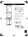 5
5
-
 6
6
-
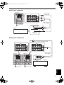 7
7
-
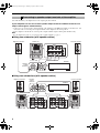 8
8
-
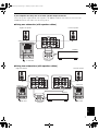 9
9
-
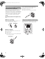 10
10
-
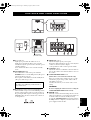 11
11
-
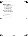 12
12
-
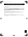 13
13
-
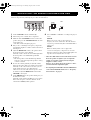 14
14
-
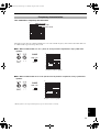 15
15
-
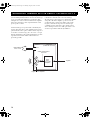 16
16
-
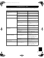 17
17
-
 18
18
-
 19
19
-
 20
20
-
 21
21
-
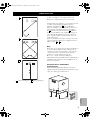 22
22
-
 23
23
-
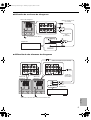 24
24
-
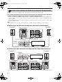 25
25
-
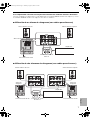 26
26
-
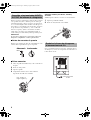 27
27
-
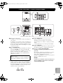 28
28
-
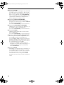 29
29
-
 30
30
-
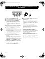 31
31
-
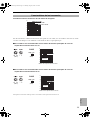 32
32
-
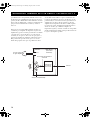 33
33
-
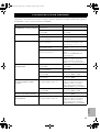 34
34
-
 35
35
-
 36
36
-
 37
37
-
 38
38
-
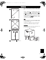 39
39
-
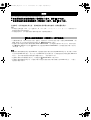 40
40
-
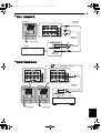 41
41
-
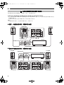 42
42
-
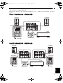 43
43
-
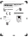 44
44
-
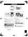 45
45
-
 46
46
-
 47
47
-
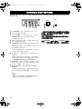 48
48
-
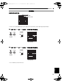 49
49
-
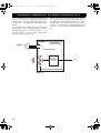 50
50
-
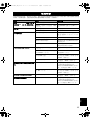 51
51
-
 52
52
-
 53
53


Yamaha YST-SW515 El manual del propietario
- Tipo
- El manual del propietario
En otros idiomas
- English: Yamaha YST-SW515 Owner's manual
- 日本語: Yamaha YST-SW515 取扱説明書
Documentos relacionados
-
Yamaha NS-SW310 El manual del propietario
-
Yamaha NS-SW700 El manual del propietario
-
Yamaha YST-SW012 El manual del propietario
-
Yamaha NS-SW210 El manual del propietario
-
Yamaha YST-FSW100 El manual del propietario
-
Yamaha YST-SW225 El manual del propietario
-
Yamaha YST-SW315 El manual del propietario
-
-
Yamaha YST-RSW300 El manual del propietario
-