
#2031 (E,S,F) 10/29/03
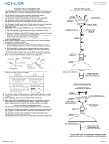
STANDARD SHADE INSTALLATION INSTRUCTIONS:
ENGLISH
1. Through bottom opening of shade, install counter ring over shade washer onto threaded socket until
shade is secure. Through top opening of shade, install light bulb (not included). See relamping label
at socket area for bulb type and maximum allowed wattage.
ESPAÑOL
1.
Introduzca el casquillo a través de la apertura inferior de la pantalla y coloque la arandela de
la pantalla por encima del casquillo; inserte el anillo de seguridad sobre el casquillo y la
arandela de la pantalla, hasta que la pantalla esté bien fijada. Introduzca las bombillas a
través de la apertura inferior de la pantalla (bombillas no incluidas). Lea la etiqueta de
reemplazo para las bombillas que se encuentra cerca del casquillo, para saber el tipo y la
cantidad máxima permisible de vatios.
FRANÇAIS
1. Introduisez douille à travers l'ouverture inférieure de l'abat-jour et placez la rondelle de
l'abat-jour par-dessus douille; insérez l'anneau de sécurité par-dessus douille et la rondelle
de l'abat-jour, jusqu'à ce que l'abat-jour soit bien solide. Introduisez les ampoules à travers
l'ouverture supérieure de l'abat-jour. (Ampoules non incluses) Consultez l'étiquette de
remplacement d'ampoule, située près de douille, pour connaître le type d'ampoule et le
wattage maximum permis.
ENGLISH
1. Remove counter rings from threaded sockets.
2. Install shade onto fitters by fastening counter ring back onto threaded sockets.
3. Install bulbs (not included). See relamping label at socket area for type and maximum allowed
wattage.
ESPAÑOL
1.
Quite el anillo de seguridad de los casquillos.
2.
Instale la pantalla en el casquillo atornillando los anillos de seguridad sobre los casquillos
enroscados.
3.
Instale la bombilla (no incluida). Lea la etiqueta de reemplazo para las bombillas que se
encuentra cerca del casquillo, para saber el tipo y la cantidad máxima permisible de vatios.
FRANÇAIS
1.
Retirez l'anneau de fixation des douilles.
2.
Installez les abat-jour sur les adaptateurs, en vissant les anneaux de sécurité sur les douilles
filetées.
3.
Installez les ampoules (non incluses). Consultez l'étiquette de remplacement d'ampoule,
située près de douille, pour connaître le type d'ampoule et le wattage maximum permis.
ENGLISH
1. Install glass shade onto fitter by locking with thumb screws.
2. Install bulbs (not included). See relamping label at socket area for type and maximum allowed
wattage.
ESPAÑOL
1. Instale la pantalla sobre el recubrimiento con los tornillos manuales.
2.
Instale la bombilla (no incluida). Lea la etiqueta de reemplazo para las bombillas que se
encuentra cerca del casquillo, para saber el tipo y la cantidad máxima permisible de vatios.
FRANÇAIS
1. Installez l'abat-jour sur le recouvrement, á l'aide des vis a serrage manuel.
2.
Installez les ampoules (non incluses). Consultez l'étiquette de remplacement d'ampoule,
située près de douille, pour connaître le type d'ampoule et le wattage maximum permis.
Counter Ring
Anillo de Seguridad
Anneau de Fixation
Counter Ring
Anillo de Seguridad
Anneau de Fixation
Socket
Casquillo
Douille
Socket
Casquillo
Douille
Socket
Casquillo
Douille
Shade
Pantalla
Abat-jour
Shade
Pantalla
Abat-jour
Shade
Pantalla
Abat-jour
Bulb (not included)
Bombilla (no incluida)
Ampoule (Non incluse)
Bulb (not included)
Bombilla (no incluida)
Ampoule (Non incluse)
Bulb (not included)
Bombilla (no incluida)
Ampoule (Non incluse)
Fitter
Recubrimiento
Recouvrement
Fitter
Recubrimiento
Recouvrement
Thumb Screw
Tornillo Manual
Vis Manuel
Before continuing with below steps, first follow enclosed
installation instructions for electrical and fixture installation
onto outlet box.
Antes de continuar con debajo pasos, siga primero el
instrucciones de instalación incluida para la instalación
eléctrica y de la lampara sobre la caja de salida eléctrica.
Avant de continuer au-dessous des étapes, suivez d'abord les
instructions d'installation incluses pour l'installation électrique
et de montage sur la boîte de sortie électrique.
IMPORTANT: TURN OFF POWER AT MAIN FUSE OR CIRCUIT
BREAKER BOX BEFORE STARTING INSTALLATION
IMPORTANTE: CORTE LA ALIMENTACIÓN ELÉCTRICA,
CERRANDO EL INTERRUPTOR CENTRAL O QUITANDO EL FUSIBLE
DEL PANEL CENTRAL ANTES DE COMENZAR EL ENSAMBLE.
IMPORTANT: COUPER L’ALIMENTATION ÉLECTRIQUE AU
BOÎTIER CENTRAL (DISJONCTEUR OU FUSIBLES), AVANT DE
COMMENCER L’INSTALLATION
MURRAY FEISS
©MURRAY FEISS IMPORT CORP.
1. Attach mounting bar securely to ceiling
junction box with two machine screws
(supplied with junction box) through
slot at each end of mounting bar. Note:
mounting bar should be installed with
"GND" imprint and/or two dimples
facing down.
2. Fasten one hex nut about 3/4" down
from one end of threaded pipe. Then
screw same end of threaded pipe into
center hole in mounting bar. At this
point test install the canopy onto ceiling
through this threaded pipe and make
certain 3/8" of pipe protrude below the
canopy. If not, then adjust the threaded
pipe location by screwing up or down
accordingly. Once correct threaded pipe
location has been adjusted, remove
canopy and tighten hex nut against
mounting bar. Make certain not to spin
threaded pipe during tightening.
3. Fasten another hex nut onto bottom end
of threaded pipe. Bring up 1/2" from
bottom end of pipe to bottom side of hex
nut. Then fasten screw collar into same
end of pipe and lock into position by
tightening hex nut.
4. Take one adjustable chain link, twist
open the locking tube, and then hook
onto fixture loop and onto one end of
chain. Close back the locking tube.
5. At this point decide how much chain to
use, including one additional adjustable
chain link at top end, so the fixture
hangs at desired height. Spread open
the chain link you have decided to
remove and discard unused links.
6. Slide collar ring and then canopy down
the chain.
7. Take another adjustable chain link,
twist open the locking tube, and then
hook onto top end of chain. Then
grabbing onto chain firmly lift fixture
and hook the same adjustable chain link
onto screw collar which has been
mounted onto ceiling. Close back the
locking tube of adjustable chain link.
8. Take the fixture ground wire (without
plastic insulation) and weave up through
the chain links, and then through screw
collar and threaded pipe. Repeat with
fixture wires (with plastic insulation).
9. Cut any excess fixture wires and
ground wire leaving only about 8"
length from top end of threaded pipe.
Take fixture wires and tie a knot above
threaded pipe. Then split fixture wires
and strip off 3/4" of plastic insulation
from each end.
10. Fixture wires connection:
Connect fixture wires to supply wires per
below chart. Wire connectors not
included; and use electrical tape to
secure wire connector and wires
together.
Note: Make certain no loose conductors
protrude outside of wire connectors.
And make certain all wires are securely
held together by wire connectors.
11. Ground wire connection:
Connect fixture ground wire to supply
ground wire (usually with green
insulation) with wire connector.
Note: If there is no supply ground wire
at ceiling juction box then attach fixture
ground wire securely onto green
grounding screw located at mounting
bar.
Important: Never connect ground
wire to black or white supply wires.
12. Once all wires are connected, tuck
them carefully into junction box. Then
raise canopy against the ceiling and lock
into position by screwing collar ring
onto screw collar.
(E) 05/21/03
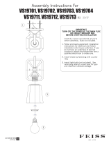
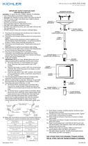
STANDARD CHAIN SUSPENDED FIXTURE INSTALLATION INSTRUCTIONS #2000:
MURRAY FEISS
IMPORTANT: TURN OFF POWER AT MAIN FUSE OR CIRCUIT
BREAKER BOX BEFORE STARTING INSTALLATION.
Connect Clear, Brown,
Gold or Black *Parallel
Wire without tracer
(round & smooth) or Black
Fixture Wire to:
Black or Red Supply Wire or
Insulated Wire (other than
green) with copper
conductor
Connect Clear, Brown,
Gold or Black *Parallel
Wire with tracer (square &
ridged) or White Fixture
Wire to:
White Supply Wire or
Insulated Wire (other than
green) with silver conductor
SUPPLY
GROUND
WIRE
KNOT
CEILING
JUNCTION
BOX
FIXTURE
GROUND
WIRE
FIXTURE
WIRES
3/4"
1/2"
SUPPLY
WIRES
MOUNTING
BAR
HEX NUTS
LOCKING
TUBE
THREADED
PIPE
SCREW
COLLAR
CANOPY
COLLAR
RING
CHAIN
FIXTURE
LOOP
ADJUSTABLE
CHAIN LINK
ADJUSTABLE
CHAIN LINK
MACHINE
SCREWS
(NOT
SUPPLIED)
Ridged
Smooth
Silver
Copper
* Fixtures normally use
parallel wires (SPT 1 &
SPT 2), of which the tracer
wire is shaped square or
ridged and the without
tracer wire is shaped round
or smooth.
Transcripción de documentos
STANDARD SHADE INSTALLATION INSTRUCTIONS: IMPORTANT: TURN OFF POWER AT MAIN FUSE OR CIRCUIT BREAKER BOX BEFORE STARTING INSTALLATION IMPORTANTE: CORTE LA ALIMENTACIÓN ELÉCTRICA, CERRANDO EL INTERRUPTOR CENTRAL O QUITANDO EL FUSIBLE DEL PANEL CENTRAL ANTES DE COMENZAR EL ENSAMBLE. IMPORTANT: COUPER L’ALIMENTATION ÉLECTRIQUE AU BOÎTIER CENTRAL (DISJONCTEUR OU FUSIBLES), AVANT DE COMMENCER L’INSTALLATION #2031 (E,S,F) 10/29/03 Before continuing with below steps, first follow enclosed installation instructions for electrical and fixture installation onto outlet box. Antes de continuar con debajo pasos, siga primero el instrucciones de instalación incluida para la instalación eléctrica y de la lampara sobre la caja de salida eléctrica. Avant de continuer au-dessous des étapes, suivez d'abord les instructions d'installation incluses pour l'installation électrique et de montage sur la boîte de sortie électrique. ENGLISH 1. Through bottom opening of shade, install counter ring over shade washer onto threaded socket until shade is secure. Through top opening of shade, install light bulb (not included). See relamping label at socket area for bulb type and maximum allowed wattage. Bulb (not included) Bombilla (no incluida) Ampoule (Non incluse) ESPAÑOL 1. Introduzca el casquillo a través de la apertura inferior de la pantalla y coloque la arandela de la pantalla por encima del casquillo; inserte el anillo de seguridad sobre el casquillo y la arandela de la pantalla, hasta que la pantalla esté bien fijada. Introduzca las bombillas a través de la apertura inferior de la pantalla (bombillas no incluidas). Lea la etiqueta de reemplazo para las bombillas que se encuentra cerca del casquillo, para saber el tipo y la cantidad máxima permisible de vatios. Shade Pantalla Abat-jour Counter Ring Anillo de Seguridad Anneau de Fixation FRANÇAIS 1. Introduisez douille à travers l'ouverture inférieure de l'abat-jour et placez la rondelle de l'abat-jour par-dessus douille; insérez l'anneau de sécurité par-dessus douille et la rondelle de l'abat-jour, jusqu'à ce que l'abat-jour soit bien solide. Introduisez les ampoules à travers l'ouverture supérieure de l'abat-jour. (Ampoules non incluses) Consultez l'étiquette de remplacement d'ampoule, située près de douille, pour connaître le type d'ampoule et le wattage maximum permis. Socket Casquillo Douille Fitter Recubrimiento Recouvrement ENGLISH 1. Remove counter rings from threaded sockets. 2. Install shade onto fitters by fastening counter ring back onto threaded sockets. 3. Install bulbs (not included). See relamping label at socket area for type and maximum allowed wattage. Socket Casquillo Douille ESPAÑOL 1. Quite el anillo de seguridad de los casquillos. 2. Instale la pantalla en el casquillo atornillando los anillos de seguridad sobre los casquillos enroscados. 3. Instale la bombilla (no incluida). Lea la etiqueta de reemplazo para las bombillas que se encuentra cerca del casquillo, para saber el tipo y la cantidad máxima permisible de vatios. Shade Pantalla Abat-jour Counter Ring Anillo de Seguridad Anneau de Fixation FRANÇAIS 1. Retirez l'anneau de fixation des douilles. 2. Installez les abat-jour sur les adaptateurs, en vissant les anneaux de sécurité sur les douilles filetées. 3. Installez les ampoules (non incluses). Consultez l'étiquette de remplacement d'ampoule, située près de douille, pour connaître le type d'ampoule et le wattage maximum permis. Bulb (not included) Bombilla (no incluida) Ampoule (Non incluse) Fitter Recubrimiento Recouvrement ENGLISH 1. Install glass shade onto fitter by locking with thumb screws. 2. Install bulbs (not included). See relamping label at socket area for type and maximum allowed wattage. Thumb Screw Tornillo Manual Vis Manuel ESPAÑOL 1. Instale la pantalla sobre el recubrimiento con los tornillos manuales. 2. Instale la bombilla (no incluida). Lea la etiqueta de reemplazo para las bombillas que se encuentra cerca del casquillo, para saber el tipo y la cantidad máxima permisible de vatios. Socket Casquillo Douille FRANÇAIS 1. Installez l'abat-jour sur le recouvrement, á l'aide des vis a serrage manuel. 2. Installez les ampoules (non incluses). Consultez l'étiquette de remplacement d'ampoule, située près de douille, pour connaître le type d'ampoule et le wattage maximum permis. Shade Pantalla Abat-jour Bulb (not included) Bombilla (no incluida) Ampoule (Non incluse) ©MURRAY FEISS IMPORT CORP. M U R R A Y F E I S S STANDARD CHAIN SUSPENDED FIXTURE INSTALLATION INSTRUCTIONS #2000: (E) 05/21/03 CEILING JUNCTION BOX SUPPLY GROUND WIRE SUPPLY WIRES FIXTURE WIRES 3/4" KNOT MOUNTING BAR ADJUSTABLE CHAIN LINK LOCKING TUBE CANOPY COLLAR RING CHAIN ADJUSTABLE CHAIN LINK FIXTURE LOOP 1/2" FIXTURE GROUND WIRE IMPORTANT: TURN OFF POWER AT MAIN FUSE OR CIRCUIT BREAKER BOX BEFORE STARTING INSTALLATION. 1. Attach mounting bar securely to ceiling junction box with two machine screws (supplied with junction box) through slot at each end of mounting bar. Note: mounting bar should be installed with "GND" imprint and/or two dimples facing down. 2. Fasten one hex nut about 3/4" down from one end of threaded pipe. Then screw same end of threaded pipe into center hole in mounting bar. At this point test install the canopy onto ceiling MACHINE through this threaded pipe and make SCREWS certain 3/8" of pipe protrude below the (NOT canopy. If not, then adjust the threaded SUPPLIED) pipe location by screwing up or down accordingly. Once correct threaded pipe HEX NUTS location has been adjusted, remove THREADED canopy and tighten hex nut against mounting bar. Make certain not to spin PIPE threaded pipe during tightening. SCREW COLLAR 3. Fasten another hex nut onto bottom end of threaded pipe. Bring up 1/2" from bottom end of pipe to bottom side of hex nut. Then fasten screw collar into same end of pipe and lock into position by tightening hex nut. 4. Take one adjustable chain link, twist open the locking tube, and then hook onto fixture loop and onto one end of chain. Close back the locking tube. 5. At this point decide how much chain to use, including one additional adjustable chain link at top end, so the fixture hangs at desired height. Spread open the chain link you have decided to remove and discard unused links. 6. Slide collar ring and then canopy down the chain. 7. Take another adjustable chain link, twist open the locking tube, and then hook onto top end of chain. Then grabbing onto chain firmly lift fixture and hook the same adjustable chain link onto screw collar which has been mounted onto ceiling. Close back the locking tube of adjustable chain link. 8. Take the fixture ground wire (without plastic insulation) and weave up through the chain links, and then through screw collar and threaded pipe. Repeat with fixture wires (with plastic insulation). M U R R A Y 9. Cut any excess fixture wires and ground wire leaving only about 8" length from top end of threaded pipe. Take fixture wires and tie a knot above threaded pipe. Then split fixture wires and strip off 3/4" of plastic insulation from each end. 10. Fixture wires connection: Connect fixture wires to supply wires per below chart. Wire connectors not included; and use electrical tape to secure wire connector and wires together. Connect Clear, Brown, Connect Clear, Brown, Gold or Black *Parallel Gold or Black *Parallel Wire without tracer Wire with tracer (square & (round & smooth) or Black ridged) or White Fixture Fixture Wire to: Wire to: Black or Red Supply Wire or White Supply Wire or Insulated Wire (other than Insulated Wire (other than green) with silver conductor green) with copper conductor * Fixtures normally use parallel wires (SPT 1 & Copper SPT 2), of which the tracer wire is shaped square or ridged and the without tracer wire is shaped round Silver or smooth. Smooth Ridged Note: Make certain no loose conductors protrude outside of wire connectors. And make certain all wires are securely held together by wire connectors. 11. Ground wire connection: Connect fixture ground wire to supply ground wire (usually with green insulation) with wire connector. Note: If there is no supply ground wire at ceiling juction box then attach fixture ground wire securely onto green grounding screw located at mounting bar. Important: Never connect ground wire to black or white supply wires. 12. Once all wires are connected, tuck them carefully into junction box. Then raise canopy against the ceiling and lock into position by screwing collar ring onto screw collar. F E I S S-
 1
1
-
 2
2
Feiss VS10503-ORB Guía de instalación
- Tipo
- Guía de instalación
- Este manual también es adecuado para
en otros idiomas
- English: Feiss VS10503-ORB Installation guide
Artículos relacionados
Otros documentos
-
 Generation Lighting VS19711 Instruction Sheet
-
IKEA SUNNEBY Manual de usuario
-
IKEA HEMMA Manual de usuario
-
IKEA 503.865.80 Instrucciones de operación
-
IKEA JALLBY Manual de usuario
-
 Kichler Lighting 43152AP Manual de usuario
-
 Kichler Lighting 42580OZ Manual de usuario
-
Kichler 82316 Guía de instalación
-
 Kichler Lighting 82266 Manual de usuario
-
Seagull Lighting 7715502EN3-962 Guía de instalación


