Sears PD4231 Manual de usuario
- Tipo
- Manual de usuario

®
0W E
AL
'S
MODEL #
SERIAL #
PD/PH 4801
PD/PH 6801
PD/PH 623,1
PD/PH 4231
READ AND SAVE THESE
[LEA Y CONSERVE ESTAS
INSTALLATION
INSTALACION
MAINTENANCE
MANTENIMtENTO
|NSTRUCT[ONS
|NSTRUCC|ONES
D SAFETY
SEGURIDAD
D TROUBLE SHOOTING
TRAZANDO FALLAS
Ce_ratuladons: You have purchased a product of superior performance and design, which will
give the best service when properly installed, operated and maintained.
FELICITACIIONE$: Usted acaba de comprar un producto con un disefio y rendimiento superior,
que [e dar_ e[ meier servicio cuando sea propiamente instaiado, operado, y mantenido.
WARNING
. WARNING: To Reduce The Risk Of Fire Or Electrical Shock,
Do Not Use This Fan With Any SoW State Speed Control
Device.
* A[ways disconnect electrical power tothe cooler beforeworking
on cooler
, Do not remove side panels while cooter is running,
• Do not _ocate cooler near exhaust or vent pipes as odors or
fumes may be drawn into the unlt:.
, Besure cooier isconnected to proper line voltage stamped on
b_ower motor and pump motor specification plate, NOTE:
iMPROPER VOLTAGE WILL VOID MOTOR WARRANTY,
* ]'HE USEOF AN ANODE DEVICEOR C}iEMiCAL ADDITIVES
OR COOLER TREATMENTSIN THiS COOLER WILL VOID THE
WARRANTY.
ADVERTENC[A
ADVERTENC[A: Para Reducir E[Riesgo De [ncendio O toque
Eiectrico, No Use £ste Enffiador Con Ningun Dispositivo Para
Controlar La Ve[ocidad
, Meier de| enfriador, bomba_ gabiaete Y ca_ade empa|me
tlenen que set cenedades a t_erra e[e_trica de acuerde con
redes lOSCodigos _ocalesf naclona|es.
• Siempre desconecte [acorriente de[ enfdador antes de cuaiquier
reparation.
No remueva los filtros cuando [a unidad esta funcionando.
No instale e_enffiador cerca de extractores o tubes de venteo
ya que otores o vapores pueden entrar a [a unidad,
Asegurese que e[ enffiador sea conectado a la [inea de voltaje
apropiado come Io indica la p/aca de e[ motor Y ia bomba,
Nora: ELUSO DE VOLTAJEIMPROP[O ANULA L&GARAN"TIA
DEL MOTOR,
)
ELuse DEANODES, LiM_ [ADORES, TRATAMIENTOS PARA
ENFRIADORES EN ESTA UNIDAD ANULA LA GARANT[A.
1-999_2049

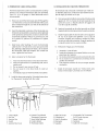
iNSTALLATiON • iN
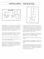
Typlo_l S_dO D|schsrge
[nsta!lat[on demands con_ection of blower opening to existing
air ducting system or to a dropper duct with a ceiiing diffuser.
In either insta_ce, building modification is ne(ess[tated. The
bottom discharge cooler is always moul_ted on the roof of
the structure_ You will require a roof stand, roof jack, flexible
duct and collar to connect to existing ductwork.
DO NOT [)RIVE NAILS OR SCREWS INTO BOSOM OFTHE
WET SECTION OF TItlE COOUR, TI4tS WiLL CAUSE iT TO
LEAK WATER AND WILL VOID THE WARRAN1_Y,
Whenever the cooler is mounted, the surface must be [eve[.
When coolers are installed in the city of LosAngeles theymust
only be installed outside of buildings.
AJ[of the electrical components that are part of this product
shall be either currently listed as part of the equipment for
intended use by a Los Angeles City recognized electrical
testing laboratory, or currently approved by the City of Los
Angeles Electrical Testing Laborato_.
La insta[acion dema:_da la conexion de la descarga de la
unidad a el existente sistema de ductos o a una caidade ducto
con difusor de de[o. En ambos casos, ]a modificacion del
edificio esnecesaria.Elenffiador de descarga inferior siempre
semo_ta en [aestructura de[ techo. Paraesto serequiere ur_
soporte de angulos, soporte de iamina ducto fiexiNe Y un
collar para conectar[o a] ducto existente.
NO CLAVE CLAVOS O TC)RNILLOS EN El,.FONDO DE LA
SECCION HUMEDA DEL ENFRIADOR_ ESTO CAUSARA
FUGAS DE AGUA Y ANULARA LA GARANI'IA.
Cuando un enfriador es montado, Jasuperfide debe estar
nivelada.
Cualquier enfriador que sea instaJado en la ciudad de Los
A%eJes tiene que set instaiado solamente en el exterior de[
edificio.
Todos los componentes electricos que son parte de este
producto deben estar corrientemente listados como parte del
equipo para el uso que se intente pot el [aboratorio de
pruebas electricas de ka Ciudad De Los Angeles 0
Corrientemente Aprobado Pot Este.

iNSTALLATION ° [NSTALAC[ON
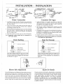
Water Connection
i.Installfloatinhoieinthesideofbottom pan oppositethe
pump.SeepartsillustrationtOroutethewaterline.Connect
perabove sketch.
2.Turnon the watertothe coolerand setfloatvalveto
maintain21/_,inchwaterdepth.The floatvalveisadjusted
by bending the float valve rod,
3. B[eed-,off:Bleed off isheipful to prevent scalefrom building
up in the cooler. A bleed-off adapter tee and tube are
furnished with the cooler for this purpose, run bleedooff
line to a proper drain,
4. h_stallfloat shield over float valve per above illustration
Note: Evaporative coolers should not he connectedto a
"so_" water system.
Drain Bushing
OVERFLOW STANDPIPE
DRA_N BUSHING
/ .........._ ...... RUBBER WASHER
"-'__ _,,_,.,. BOTTOM PAN (P]_STJC)
_"""_ LOCK NUT
Insert drain bushing through the hole in the cooler
bottompan,Attachnutsecurely,andtighten,do notuse
a wrench,Attach hoseand adapterfrom drain pump.
See illustration on page 8,
Conexi6n De[ Agua
_. Instate el flotador en el agujero proveido en el [ado de[
desposito opuesto a la bomba, Conecte e! tubo del agua
de acuerdo con la figura de arriba Y guie el tubo de
acuerdo con la i_ustracion de partes,
2, Abra el agua Y ajuste el flotador para mantener un nive[
de 2:pu[gadas de agua, £1flotador se ajusta doblando [a
variila de este.
3. E[desagOeayuda a prevenir el acumutamiento de sales en
el enfriador. Un adaptador _'T"y tubo de sangria estan
induidos en el enfriador para este proposito, guie ta [inea
de sangria a un drenaie apropiado,
4, lnstale la cubierta sobre la vaivula como se indica ardba,
Nota: Eniriadores per eiVapOr_CiOnno,deben set cenec[ados
a un slstemade agua blanda,
Buje De Drena e
Z TU_ DE RESBOSAGERO
BUJE DE DRENAJE
--_' _ EMPAOUE
FC_DO DE PLASTtGO
_Z_ _ TUEBCA
de [a mano, no use herramien_. Yea ilustraci6n en
pagina 8.
[}lower Belt Adiustment
Correct belt adiustment and alignment isimportant asincorrect
adiustment increases power consumption and shortens belt
and motor life. hsta[t belt over motor and blower pulleys, (A)
Check belt tension by squeezing (deflecting)belt, Proper
tension wiii allow deflection of ]/_ to 3/1inch. (B) To increase
or decrease be[t tension, loosen bolt in slot of motor support
bracket. Adjust belt to desired tension and retighten bolt,
Ajuste De Banda
El ajuste correcto de Ia banda y alineamiento es importante
ya que el aiuste incorrecto aumenta el consumo de corriente
y acorta la duration de la banda y motor. [nstale [a banda
sobre ambas poleas, (A} Revise la tension de [a banda
apretando[a (defleccionandola), Una tension apropiada
permitira, una defleccion de V2 a % de putgada. (B) Para
aumentar o disminuir la tension de la banda afloje el tornillo
dei soporte de[ motor. Ajuste la banda a la tension deseada
y apriete el torniHo,
3

ELECTRICAL CONNECTIONS
FIELD WiRiNG iNSTRUCTiONS
1.MAiN POWERSUPPLY
THiS COOLER iS PREWIRED FOR 115 VOLT OR 230
VOLT, 6OHZ POWER ONLY. MAKE SURE YOU
CONNECT YOUR COOLER TO THE CORRECT VOLTAGE.
A_
B.
Remove the control box cover- (4)screws.
Remove 2"x 4" water tight junction box (3},junction Box
Cover (5),switch (4) and 1/2_chase nipple (1) and jam
nut (2) from the parts ca_ton.
C. Mount junction box to the cooler asfoffows:
D.
1_ Insertchase nipple (1)into 7/8" hole from the insideof
the cabinet (8) arid fasten it tightly to the cooler with
the 1/2" conduit jam nut (2).
2. ScrewtheJunction box (3)or_totimethreadof thechase
nipple (1) until tight and aligned vertically.
CAUTION; Make sure the power isoff to the supply
wires before proceeding with the next steps.
Connect groundwires asfollows; Referto wiring diagram
inside the control box cover.
2.
Pull the green ground wire harness from the cooler
through the chase nipple {l).
Attach the eyeletterminal of the ground wire harness
and the ground wire from the power supply to the
disconnect box (3) usingthe#10 Green Ground screw
supplied_Attach thespadeterminal of theground wire
assembly to the switch (4) ground screw.
E. Connect Li_'_eLeads as Follows:
F,
]5 Volts CooPers: Pull the bi_ackand white jumper
wires from the cooler through thechasenipple (1) into
the iunction box (3}. Attach the black iumper wire to
one screw terminal on the switch (4). Attach the hot
supply lead to the other screw terminal on the switch
Attach the white iumper wire from the cooler to the
white or neutral wire from the supply line using the
orange wire nut supplied.
2_
230 Volt Coolers: Pull the black and orange iumper
wires from the cooter through thechasenipple (1) into
theiunction box (3).Fastenthe black wire to one !oad
screwon the switch. Fastentheorange iumper wire to
the other load screw on the switch_ Fastenthe two
supply leads to the two line screws on the swtich.
Mount the switch (4) onto the iunction box (3) with the
on position up and the ground screw on the switch
down.
G, Mount thejunction box cover (5) onto thejunction box
making certain that the gasket fits properly a[[ the way
around the periphery of the iunction box (3),
INSTRUCC[ONES DE ALAMBRADO
CONEXIONES ELECTRICAS
i. FUENTE DE PODER PRINCIPAL
ESTEENFRIADOR HA SIDO ALAMBRADO PARA
OPERAR CON CORR[ENT[ DE 115 VO[TIOS 60HZ
SOLAMENTE
a.
2_
Remueva tatapadera de [acasade control- (4) tornillos.
Remueva la caia impermeable 2"x 4"de empa[me (3),
tapadera de caia(5), interruptor(4) Y el nipie de encaie
de T/2"(I )e[ niple deencaje de 1/2°(1) contratuerca (2)
de la caia de cart6n.
Monte la caja de empalme como sigue:
Co[oque elnipie de encaje (1)en el agujero de 7/8_'de
adentro de/gabinete(8)Yasegureloconlacontratuerca
(2).
Atornil[e [acajade empaime (31en [aroscade el niple
(1)basraque quede apretadayvetticatmenteaiineada_
PRECAUC!ON: Asegurese que la corriente est_
desconectada antes de proceder con los siguientes
pasos,
D. Conecte los a!ambres de tierra como sigue; Yea el
diagrama de alambrado dentro de la tapaderade/a caia
de control.
2_
E_
F_
G_
)ale el alambre verde altrav_s de el niple (1)
Conecte [aterminat de oiiito deI alambrede tierray el
alambre de tierra de la fuente de poder a la caja de
empalme (3) usando el tornillo verde de tierra #10
incluido. Conecte [aterminal de espada de[ alambre
de tierra a[tomi/[o de tierra del interruptor (4).
Conecte LosA/ambres de La Linea de Corrieme Como
Sigue:
Enfriadoresde 115 voltios: Jalelosalambresde cierre
negro y el bianco del enfriador atrav_s del nipie (t)
hacia la caja de empaime (3)_Conecte e/alambre
negro de cierre a un tomil[o de [a terminal en el
interruptor (4). Conecte el a el
otto tomillo en [aterminal del hterruptor, Conec:te el
aiambre de cierre blanco del enfriador al alambre
b/anco o neutral de la Iinea de corriente usando el
cono aislante anaraniado proveido.
2_
Enfriadoresde 230 Vol:tios: _alelosalambresde cierre
negro y el anaraniado del enfriador atrav_sde_nip[e
(1) hacia/a caja de empalme (3), Conecte el alambre
de cierrenegro a unade lasterminales decarga(Load)
del interruptor. Conecte el alambre de derre
anaranjado a [aotraterminal de cargade[interruptor.
Conecte losdosa[ambresde corriente a[asterminales
marcadas supply (Fuente) del it'_terruptor.
Monte el interruptor (4) en [aca]a (3) con taposici6n de
prendido hacia arriba y el tomiHo de tierra hada abajo.
Monte la tapadera de la caja (5) asegurandose que el
empaque cierre el periferio de la caja (3).

Jl. THERMOSTAT CABLE |NSTALLATION |L INSTA_C[_N DEL CABLE DEL TERMOSTATO
The thermostat for this cooler is connected to the cooler by
means of a 6 conductor thermostat cable (not provided).
Type CL2, 18 or 20 gauge, UL listed thermostat wire is
recommended.
A_
Route one end of the thermostat cable (9) through the
1/2'_hole in the corner post on the left sideofthe access
door and then through the 1/2_'hole in the left end of
the control box.
B, Insert the individual conductors of the thermostat ;wire
(9) into the terminal block connections on the right side
of the printed circuit board (6). Connect colored wires
to terminals asfollows: white to '_C_',brown to _H_,red
to _'L_,green to '_P_,yellow to "D_,and blue to _'R_%Tighten
screws.
C_
Install strain relief bushings (7) over the thermostat
cable into the 1/2°holes in thecorner post and control
box, allowing aslight amount of "slack',do not stretch
the thermostat cable tight. Replace the control box
cover - tighten the four screws.
D, Select a location for the thermostat
1. Mount the thermostat about 5 feet above the floor,
2, Mount the thermostat on a partitioning wall, not an
outside wail.
3_ Do not mount it near sources of heat,
4, Do not mount it in the direct draft of cooler air
registers_
5 Avoid dead air spaceswhich have titt[e air circulation,
E. Installthe thermostat usingthe "Mounting Instructions
for Thermostat" furnished with the cooler,
8
Eltermostato est_ conectado al enfriador pot medio de
un a[ambre piano de 6 conductores tipo telefono de 66
pies de largo (9) induido en Jacaja,
A,
Guie una punta de[cable de termostato (9) aitrav6s de[
aguiero de 1/2_en el poste de el [ado izquierdo de [a
puerla de acceso y despu6s altrav6s del agujero de
1/2 °de [acaja de controJes.
B. [nserte el conectador en el socket proveido en eI tado
izquierdo de[ circuito impreso (6)en la caia de contro[es.
C_
[nstaJee/sujeta cable (7)sobre el cable yen los aguieros
de 1/2_ en la esquina de[ gabinete yen ]a caja de
contro[es. Deiando una prequena cantidad de cable,
no estire etcable det termostato. Ponga la tapadera de
[a caja de[ control con los cuatro tornillos.
D. Seleccione el tugar para el termostato.
1. MonteM a 5 pies de[ piso.
2, [nsta[ee[termostato en u_a pared interior no en una
pared que de al exterior.
3. No monte el termostato cerca de una fuente de calor
4_ No Io monte en ta corriente de aire directa de [as
parri[las de[ enfriador.
5. Evite espacios muertos de aire que tengan poquita
circulaci6n.
E. Instate el termostato usando las "lnstrucciones para
montar et termostato" proveidas con el enfriador.
7 6
4 3 2 1
9 5
1. Chase Nipple
2, Jam Nut
3. Junction Box
4 Switch
5, junction Box Cover
6, Printed Circuit Board
Thermostat Connector
7, Strain Relief Bushings
8, Cooler cabinet
9. Thermostat Cable
/
1. Niple De Encaje
2. Contratuerca
3. Caja De Empalme
4, lnterruptor
5. Tapadera
6. Conectador De Termostato
En ElCircuit() tmpreso
7. Sujeta Cables
8. Gabinete
9. Cable De Termostato

MAiN NANCE ° MANTEN[M[EN
The cooler should be servicedat least once a year and more
often if required.This includescleaning,oiling, beltadjustment
(if required) and pad repJacemenL
Cleaning:
I. Remove access doors and inlet air louvers.
2. Remove the overflow standpipe from the drain bushing
and allow the reservoir to empty,
3. Use a hose with a nozzle and spray the external inlet
surfaceof the Ce[dekpadsand plasticsurfacesto _emove
scale,dirt, artd foreign material A soft brush may be used
to assist removal of materials.
4. Clean the internal surfacesof the cooler with a cloth and
dean water.
5_ Rinse the cooler bottom pan thoroughly,
6. Clean the pump screen and remove any foreign material
between the pump and the hose. To remove any foreign
material in water distributor tube, remove plastic plug from
end of tube and flush tube with water. Replace plug,
7_ Touch up any scratches or bare spots on the metal surfaces
of the cooler with a suitable rust resistant paint.
Oiling:
At !east once a year you shoutd fill the oil cups on the blower
shaft bearings with SAE #20_30 NON D_TTERG_NTO_L. Oil
the motor with 30=35 drops of SAE 20.30 Non detergent oit
per bearing every two years.
Belt Adiustment:
Check belt tension, Readjust, if loose, per instructions in the
installation section of this manual
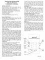
Pad Replacement.:
The Ceidek pad media should be removed and replaced if
scaie has buiff up on the outside which will restrict the airflow
and cannot be removed using the method described in the
"Cleanh_g" section above.
Replacement media is available through your dealer, install
the replacement media in the same manner as the
media was installed. Make sure that the painted stripe on
the media is properly located, See illustration below.
El enfriador require servicio a[ menos una vez pot afro o
mas si es necesario_ Esto inc[uye fimpieza, ]ubricacion, aiuste
de banda (si esta floja) y reemp[azo de[ panaL
Limpieza:
_. Remueva ]as puertas de acceso y [a parrilla.
2 Remueva el rebosadero de el buje de drenaje y vacie
el deposito de agua.
3_ Use una manguera y rocie [a superficie de ia parte externa
de[ panat con presion y [as superficies de plastico para
remover escama, tierra, y matedai extraffo Puede usar
una brocha b/andita para Hmpiar el panal,
4. Limpie los superficies internas de[ enffiador con un trapo
Y agua ]impia,
5. Enjuague e[ rondo del enfriador compietamente.
6_ Limpie el filtro de [a bomba Y remueva obietos que
obstruyan el adaptador de [a manguera en [a bomba.
Asimismo timpie el adaptador de] distribuidor de agua
a [a manguera. Remueva el tapon de piastico de[ tubo
y aplique agua a presion. Ponga e[ tapon
7. Pinte raspaduras Y puntos expuestos en ias superficies
de metal de[ enffiador con un recubrhlliento resistente
a corrosion.
Lubricac[on:
A[ menos una vez pot afio usted debe Henar [as aceiteras
en los chumaseras de la flecha con aceite de motor SAE
#20_30, NO DETERGENTE Aciete el motor con 30-35 gotas
de aciete SA[_ 2030 no detergente por chumasera coda
dos afros..
Aiuste De Banda:
Revise ]a tension de !abanda. Reaiuste, si esta floia, siguiendo
[as instrucciones en [a seccion de operacion de este manual
Reemplazo de[ Pana[ (Ceidek):
E[pana] ce[dek debe set removido y remp]asado si ]a escama
se a acumu[ado en [a supefficie externa y restringe el f[ujo
de[ aim y no puede set removida usando los metodos descritos
en Ia se(c[on de "limpieza'.
Remp[azode[panalesdisponiblepot mediode sudistribuidor.
Insta[e e[ pana[ de remp[azo rl_._fQm__]_
_[. Asegurese que la raya pintada en el panal
quede propiamente k_sta]ada.Vea la ilustraci6n abaio
iNSiDE" MED}A
PANAL DE "ADENTRO
La página se está cargando...
La página se está cargando...

P
CLEAN
c
NG
O
NC
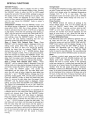
FULL AUTOMATIC: Freshwater for your evaporative coo]er
every 5 hours of operation!
How i! works..,
The Pro Cleaning System (PCS)will automatically cycle
every 5 hours of co®[er pump operation to empty the water
reservoir within 1_/!_mhwtes. This cycle allows the cooler to re_
fiiiwith freshwater. At no time iscooling capability interrupted.
The benefits of fresil water replacement on a t'egutarbasis
include reduction of mineral scale buiid4Jp, bacteria[ growth
control, reduced water consumption (b[eedooffiseliminated),
easier maintenance and longer pad life-WITHO[J! the use of
harsh chemical additives or cleaners.
The pumps used in this cooler can pump water down to
avery [ow [eveL Itisimportant to re!) acethem, if needed, with
the same pump LSP93made by Phoenix Manufacturing, h_c_
To install the PRO' Cleaning System .....
Connect one end of the water tube to the discharge outlet
of the PCS and firmly insert the other end (with drain
adapter fitting) into the cooler overflow standpipe_Avoid
"kinking" the water tube. Make sure PCSis plugged into
receptacle marked "DRAIN PUMP'g
2_
You must provide a :Y'4_or Jargergarden hose or PVC pipe
drain beneath the cooler standpipe to take thewater away
to an appropriate drain site.
Maintenance consists of cleaning the PCShl[et screen at
the beginning of each cooler season.
COMPLETAMENTE AUTOMAT[CO: Agua fresca para su
cooler cada 5 horas de operacion[
COMO TRABAJA ....
Una vez instalado, el sistema/impiador automatk;o (PCS)
funciona automaticamente cada 5 horas de operacion de [a
bomba del enfriador para vaciar e[ agua de[ deposito en 1_/_
minutos Este cic[o permite a] enfriador ]lenarse con agua
fresc& La accion enfriadora no es interrumpida.
Los beneficios de remptasar regu[armer_te con agua
fresca h_ciuye [a reduction de ta acumulacion de escama
mineral,, conlro[a el crecimiento de bacteria (la sangda es
elimininada), faci[ mantenimiento y [arga vida de_filtro o_L! ei
uso de asperos aditK,os quimicos o limpiadores.
Para resultados optimos, use este producto con Insbomb,as
LSP93 o LSP94 (bombas a bajo niwal).
Las bombas usadas en este enfl'iador pueden bombear et
agua hasta muy bajo nivel. Es importante rempIazarlas, si en
necesario, con et mismo modelo LSP93 hechas pot Phoenix
Manufacturing, Inc.
Para ffasta]ar e[ S[stema Pro de [[mp[eza ....
1. Conecte un [ado de [amanguera de agua a [adescarga de
la salida de[ [[mpiador automatico de potencia (PCS)y
firmemente inserte [a otra punta (con el adaptador de
desag0e)ene]tubo rebosaderode]enfriador. Evite'Dob[ar"
la manguera de agua.
Asegurese que e[ PCSest_ (nchufado en e[ receptacu[a
rnarcado "Drain Pump".
2, Usted tiene que proveer una manguera de iardin de :_/_de
pulgada o un tubo de PVC debaio de e[ rebosadero del
enfriador para Hevar e[ agua a un [ugar apropiado para
drenaje.
EImantenimiento consiste en [impiar e[ fi[tro de [aunidad
a[ empiezo de cada temporada de uso..
WATER
TUBE
TUBO DE
AGUA
DRAIN
ADAPTER ,_,
(MUSTBE USEDt_.
OVERFLOW
STANDPIPE
DRAIN PUMP
DISCHARGE
OUTLET
ADAPTADQR
DE DESAGUE ,_
TUBE DE
REBOSADERO
S¢,&IDA DE DESCARGA DE
L& BOMBA DE DESAGOE

Troubleshooting
Shourd a_ obvious probIem occur with your cooler consult the foiiowing table, ff you cannot correct the problem, contac_ a q_Ja[if_edsewice representative,
PROBLEM
Water
Overflow
Blower
will not
operate
Fuse blown or circuit
breaker tripped
Dry Pads
Cooler
noisy
Inadequate
air flow
PROBABLE CAUSE
Float movement obstructed
Float vatve defective
Motor defective
Control / thermostat defective
Blower bdt broken
-Wii°[ wired incorrectly
Motor fauJty
Water pump faulty
Water level _ffcorrect ....
Pump intake dogged
Water pump fauky
Clogged water line
Distributor tube dogged
Control/thermostat faulty
WMng faulty
Motor sheave loose
Blower set screws loose
Pad plugged
Belt loose
h_suff[cient exhaust vent area
CORRECTWE ACTION
Free float from obstruction
Replace float assembly
Replace motor
Repla(e controi or thermostat
Replace beff
Replace motor
Replace water pump
Adiust float to 2" water depth
Remove obstruction
Replace water pump
Locate and free obstruction
Clear debris from tube
Replace control / or thermostat
Repair or replace defective wMng
Tighten set screws
Tighten set screws
Adjust belt tension
_(/)pen windows or doors
Trazando Fa[Jas
Encaso de alguna fa![a en su enftlador consu[te Iatab_a 2, '_Traza_@ofal[as/' Esta_ablaes una guia para _osprobIemas mas obvios. Si usted no p_aedecorregk eJ
problemapongaseen contac_ocon un competenterepresentar_tede serqcio.
PROBEEMA
De Agua
La Turbina
No Funciona
Fusible Quemado
Cortacircuito
seapaga
Filtros Secos
Ruidoso
Fiuio De Aim
[nadecuado
PROBABLE CAUSA ACaON CORRE_WA
Valvuia fuera de aiuste Ajuste Va[vula a 2 _3j_adas de profun@dad de agua.
Fiotador atorado
Vabuia defectuosa
ElectrMdad desconectada
Motor defectuoso
Control o termostato defectuoso
Banda rota
FaHasel_ el a[ambrado o aJambrado incorrectamente
Motor defectuoso
Bomba defectuosa
Nivei de agua incorrecto
Entradade asua en ]a bomba obstruida
Bornba defectuosa
Linea de ag ada
Tubo De distdbudor ta ......................................................
...Cot3o_/term ta defectuoso
Alambre defectuoso
Turbina roza con ia:caia de esta
Po/eamotriz ruidosa
r
Filtro tapado
Banda flo_ .................................................
hsuficiente escape de aire en el area venti[ada
Libere el flotador
Rempiasela
Revise:corriente, rec£¢2ta [o y cordon
lase el motor
Remplaseel interruptor o termostato
_R_)areo rempiase Ios alambres defectuosos
Re_p[ase e[ motor
Ajuste vaivula a 2 asj_e_rofundidad
.i_@ie [a entrada de a&ua
Localice y [ibere Ia obstruction
LocaJize y limpie la obstruccion en ei tubo
[ase control o termostato
Reaiinie turbina
3_riem los mrniJfos opmsores
impie O rempbse filtro
_uste [a tension de esta
Abra ventanas o j2uertas

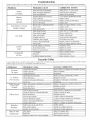
Aerocool Pro Series Evaporative Coolers - Replacement Parts List
Aerocool Pro Series Enfriador Evaporativo - Lista Reemplazo de Partes
Replacement Part Parte de Reemptazo PD4801A PD4231A PH4801A PH4231A PD6801A PD6231A PH6801A PH6231A
1 Wet Section (Cabinet)
2 Water Distributor Assy.
3 Blower Assy - Complete
4 Motor Mount
5 Pump
6 Overflow Standpipe Kit
7 Float Valve Assembly
8 Plastic Liner & Tray
9 Pump Receptacle
10 Motor Receptacle
Secci6n H0meda (Gabinete)
Distribuidor de Agua
Soplador Ensamble
Montadura del Motor
Bomba
Tubo de Rebosadero
Valvula Flotador
Revestidor y Soporte
Receptaculo de Bomba
Receptaculo de Motor
5-1-47
5-6-54
5-3-67
5-3-85
5-6-34
5-6-5
5-6-1
5-6-162
5-7-60
5-7-61
5-1-47 5-1-47 5-1-47 5-1-46 5-1-46 5-1-46 5-1-46
5-6-54 5-6-54 5-6-54 5-6-54 5-6-54 5 -6-54 5-6-54
5-3-67 5-3-68 5-3-68 5-3-69 5-3-69 5-3-70 5-3-70
5-3-85 5-3-85 5-3-85 5-3-86 5-3-86 5-3-86 5-3-86
5-6-57 5-6-34 5-6-57 5-6-34 5-6-57 5-6-34 5-6-57
5-6-5 5-6-5 5-6-5 5-6-5 5-6-5 5-6-5 5-6-5
5-6-1 5-6-1 5-6-1 5-6-1 5-6-1 5-6-1 5-6-1
5-6-162 5-6-162 5-6-162 5-6-161 5-6-161 5-6-161 5-6-161
5-7-70 5-7-60 5-7-70 5-7 -60 5-7-70 5-7 -60 5-7 -70
5-7-71 5-7-61 5-7-71 5-7-61 5-7-71 5-7-61 5-7-71
11 Louver Inlet Panel Panal de Entrada con Rejillas 5-1-49 5-1-49 5-1-49 5-1-49 5-1-48 5-1-48 5-1-48 5-1-48
12 Wet Section Top Tapa Secci6n H0meda 5-1-67 5-1-67 5-1-67 5-1-67 5-1-67 5-1-67 5-1-67 5-1-67
13 Belt Banda 5-3-26 5-3-26 5-3-27 5-3-27 5-3-25 5-3-25 5-3-73 5-3-73
14 Blower Pulley Polea Impulsa Turbina 5-3-71 5-3-71 5-3-71 5-3-71 5-3-72 5-3-72 5-3-72 5-3-72
15 Bearing Assy (set of 2) Chumaceras (juego de 2) 5-3-38 5-3-38 5-3-38 5-3-38 5-3-39 5-3-39 5-3-39 5-3-39
Leather Washer (12 pcs)
16
17
18
19a
19b
2O
Shaft
Blower Wheel
Pad Media - High Density
Pad Media - Low Density
Winterization Panel *
Arandela de Vaqueta (12 pzs)
Eje
Turbina
Panal - Alta Densidad
Panal - Baja Densidad
Cobierta para el Invierno *
5-3-8
5-3-2
5-3-35
5-2-117
5-2-118
ACWC48
5-3-8
5-3-2
5-3-35
5-2-117
5-2-118
ACWC48
5-3-8
5-3-2
5-3-35
5-2-117
5-2-118
ACWC48
5-3-8
5-3-2
5-3-35
5-2-117
5-2-118
ACWC48
5-3-8
5-3-3
5-3-36
5-2-115
5-2-116
ACWC68
5 -3-8
5 -3-3
5-3-36
5-2-115
5-2-116
ACWC68
5-3-8
5-3-3
5-3-36
5-2-115
5-2-116
ACWC68
5-3-8
5-3-3
5-3-36
5-2-115
5-2-116
ACWC68
21 Motor Sheave Polea Motriz 5-3-129 5-3-129 5-3-129 5-3-129 5-3-30 5-3-30 5-3-30 5-3-30
22
23
24
25
Thermostat (wall) Thermostato (de Pared)
Control Box Assembly Ensamble Caja de Control
(with Receptacles) (con ReceptacuLos)
Disconnect Switch & Cover Interruptor y Cubrieta
Motor Kit i Juego de Motor
NOT SHOWN _ -NO ILLUSTRADO
5-7-104
5-7-107
5-7-64
MK42C
5-7-104
5-7-108
5-7-75
MK45C
5-7-104
5-7-107
5-7-64
MK42C
5-7-104
5-7-108
5-7-75
MK45C
5-7-104
5-7-105
5-7-64
MK46C
5-7-104
5-7-106
5-7-75
MK47C
5-7-104
5-7-105
5-7-64
MK46C
5-7-104
5-7-106
5-7-75
MK47C
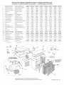
23
10
BLOWER ASSEMBLY
SOPLADOR ENSAMBLE
12
f
1 _ iNCLUDES TOP
#NCLUYE TAPA)
SPACER - INCLUDED
WITH 1£a OR t9b
PANAL- tNCLUIDO
CON 19a 019b
19a
11
DOWN DISCHARGE SHOWN, SIDE DISCHARGE SIMILAR
DESCARGA de ABAJO ILLUSTRADO, DESCARGA de LADO SIMILAR 1-999-2283 Date: 1/05
Transcripción de documentos
0W E 'S ® AL MODEL # SERIAL # PD/PH PD/PH PD/PH PD/PH 4801 6801 623,1 4231 READ AND SAVE THESE |NSTRUCT[ONS [LEA Y CONSERVE ESTAS |NSTRUCC|ONES INSTALLATION INSTALACION MAINTENANCE MANTENIMtENTO Ce_ratuladons: You have purchased a product give the best service when properly D SAFETY SEGURIDAD D TROUBLE SHOOTING TRAZANDO FALLAS of superior performance and design, installed, operated and maintained. which will FELICITACIIONE$: Usted acaba de comprar un producto con un disefio y rendimiento superior, que [e dar_ e[ meier servicio cuando sea propiamente instaiado, operado, y mantenido. WARNING . WARNING: To Reduce The Risk Of Fire Or Electrical Shock, Do Not Use This Fan With Any SoW State Speed Control Device. ADVERTENC[A ADVERTENC[A: Para Reducir E[ Riesgo De [ncendio O toque Eiectrico, No Use £ste Enffiador Con Ningun Dispositivo Para Controlar La Ve[ocidad , Meier de| enfriador, bomba_ gabiaete Y ca_a de empa|me tlenen que set cenedades a t_erra e[e_trica de acuerde con redes lOSCodigos _ocales f naclona|es. * A[ways disconnect electrical power to the cooler beforeworking on cooler , Do not remove side panels while cooter is running, • Do not _ocate cooler near exhaust or vent pipes as odors or fumes may be drawn into the unlt:. • Siempre desconecte [a corriente de[ enfdador antes de cuaiquier reparation. No remueva los filtros cuando [a unidad esta funcionando. No instale e_enffiador cerca de extractores o tubes de venteo ya que otores o vapores pueden entrar a [a unidad, , Be sure cooier is connected to proper line voltage stamped on b_ower motor and pump motor specification plate, NOTE: iMPROPER VOLTAGE WILL VOID MOTOR WARRANTY, Asegurese que e[ enffiador sea conectado a la [inea de voltaje apropiado come Io indica la p/aca de e[ motor Y ia bomba, Nora: ELUSO DE VOLTAJEIMPROP[O ANULA L& GARAN"TIA DEL MOTOR, * ]'HE USEOF AN ANODE DEVICE OR C}iEMiCAL ADDITIVES OR COOLER TREATMENTSIN THiS COOLER WILL VOID THE WARRANTY. ELuse DE ANODES, LiM_) [ADORES, TRATAMIENTOS PARA ENFRIADORES EN ESTA UNIDAD ANULA LA GARANT[A. 1-999_2049 iNSTALLATiON Typlo_l S_dO D|schsrge [nsta!lat[on demands con_ection of blower opening to existing air ducting system or to a dropper duct with a ceiiing diffuser. In either insta_ce, building modification is ne(ess[tated. The bottom discharge cooler is always moul_ted on the roof of the structure_ You will require a roof stand, roof jack, flexible duct and collar to connect to existing ductwork. DO NOT [)RIVE NAILS OR SCREWS INTO BOSOM WET SECTION OF TItlE COOUR, LEAK WATER AND • iN WILL VOID La insta[acion dema:_da la conexion de la descarga de la unidad a el existente sistema de ductos o a una caida de ducto con difusor de de[o. En ambos casos, ]a modificacion del edificio es necesaria. El enffiador de descarga inferior siempre se mo_ta en [aestructura de[ techo. Para esto se requiere ur_ soporte de angulos, soporte de iamina ducto fiexiNe Y un collar para conectar[o a] ducto existente. OFTHE TI4tS WiLL CAUSE iT TO THE WARRAN1_Y, NO CLAVE CLAVOS O TC)RNILLOS SECCION HUMEDA FUGAS DE AGUA Whenever the cooler is mounted, the surface must be [eve[. When coolers are installed in the city of LosAngeles they must only be installed outside of buildings. AJ[of the electrical components that are part of this product shall be either currently listed as part of the equipment for intended use by a Los Angeles City recognized electrical testing laboratory, or currently approved by the City of Los Angeles Electrical Testing Laborato_. EN El,.FONDO DEL ENFRIADOR_ Y ANULARA DE LA ESTO CAUSARA LA GARANI'IA. Cuando un enfriador es montado, Ja superfide debe estar nivelada. Cualquier enfriador que sea instaJado en la ciudad de Los A%eJes tiene que set instaiado solamente en el exterior de[ edificio. Todos los componentes electricos que son parte de este producto deben estar corrientemente listados como parte del equipo para el uso que se intente pot el [aboratorio pruebas electricas de ka Ciudad De Los Angeles Corrientemente Aprobado Pot Este. de 0 iNSTALLATION Water Connection i. Install float inhoieinthesideofbottom pan oppositethe pump. Seeparts illustration tOroutethewaterline. Connect perabove sketch. 2. Turn on the waterto the coolerand setfloatvalveto maintain 21/_, inchwaterdepth.The float valveisadjusted by bending the float valve rod, 3. B[eed-,off:Bleed off is heipful to prevent scale from building up in the cooler. A bleed-off adapter tee and tube are furnished with the cooler for this purpose, run bleedooff line to a proper drain, 4. h_stallfloat shield over float valve per above illustration Note: Evaporative coolers should not he connected to a "so_" water system. ° [NSTALAC[ON Conexi6n De[ Agua _. Instate el flotador en el agujero proveido en el [ado de[ desposito opuesto a la bomba, Conecte e! tubo del agua de acuerdo con la figura de arriba Y guie el tubo de acuerdo con la i_ustracion de partes, 2, Abra el agua Y ajuste el flotador para mantener un nive[ de 2: pu[gadas de agua, £1flotador se ajusta doblando [a variila de este. 3. E[desagOe ayuda a prevenir el acumutamiento de sales en el enfriador. Un adaptador _'T"y tubo de sangria estan induidos en el enfriador para este proposito, guie ta [inea de sangria a un drenaie apropiado, 4, lnstale la cubierta sobre la vaivula como se indica ardba, Nota: Eniriadores eiVapOr_CiOnno,deben a un slstemade agua blanda, per Drain Bushing / .........._ ...... "-'__ _"""_ Insert drain Z RUBBER WASHER --_' _ EMPAOUE _Z_ _ TUEBCA through the hole DE RESBOSAGERO DE DRENAJE FC_DO DE PLASTtGO in the cooler bottom pan,Attachnut securely,andtighten,do not use a wrench,Attach hoseand adapterfrom drain pump. See illustration on page 8, [}lower TU_ BUJE (P]_STJC) LOCK NUT bushing Buje De Drena e OVERFLOW STANDPIPE DRA_N BUSHING _,,_,.,. BOTTOM PAN set cenec[ados Belt Adiustment Correct belt adiustment and alignment is important as incorrect adiustment increases power consumption and shortens belt and motor life. hsta[t belt over motor and blower pulleys, (A) Check belt tension by squeezing (deflecting)belt, Proper tension wiii allow deflection of ]/_ to 3/1 inch. (B) To increase or decrease be[t tension, loosen bolt in slot of motor support bracket. Adjust belt to desired tension and retighten bolt, de [a mano, no use herramien_. pagina 8. Yea ilustraci6n en Ajuste De Banda El ajuste correcto de Ia banda y alineamiento es importante ya que el aiuste incorrecto aumenta el consumo de corriente y acorta la duration de la banda y motor. [nstale [a banda sobre ambas poleas, (A} Revise la tension de [a banda apretando[a (defleccionandola), Una tension apropiada permitira, una defleccion de V2 a % de putgada. (B) Para aumentar o disminuir la tension de la banda afloje el tornillo dei soporte de[ motor. Ajuste la banda a la tension deseada y apriete el torniHo, 3 ELECTRICAL CONNECTIONS FIELD WiRiNG iNSTRUCTiONS 1.MAiN POWER SUPPLY INSTRUCC[ONES CONEXIONES DE ALAMBRADO ELECTRICAS i. FUENTE DE PODER PRINCIPAL THiS COOLER iS PREWIRED FOR 115 VOLT OR 230 VOLT, 6OHZ POWER ONLY. MAKE SURE YOU CONNECT YOUR COOLER TO THE CORRECT VOLTAGE. (4)screws. ESTEENFRIADOR HA SIDO ALAMBRADO PARA OPERAR CON CORR[ENT[ DE 115 VO[TIOS 60HZ SOLAMENTE Remueva tatapadera de [a casa de control- (4) tornillos. a. A_ Remove the control box cover- B. Remove 2"x 4" water tight junction box (3},junction Box Cover (5), switch (4) and 1/2_chase nipple (1) and jam nut (2) from the parts ca_ton. Remueva la caia impermeable 2" x 4" de empa[me (3), tapadera de caia (5), interruptor(4) Y el nipie de encaie de T/2"(I )e[ niple de encaje de 1/2 °(1) contratuerca (2) de la caia de cart6n. C. Mount junction box to the cooler as foffows: Monte la caja de empalme como sigue: 1_ Insert chase nipple (1) into 7/8" hole from the inside of the cabinet (8) arid fasten it tightly to the cooler with the 1/2" conduit jam nut (2). 2. Screw the Junction box (3) or_totimethread of the chase nipple (1) until tight and aligned vertically. 2_ PRECAUC!ON: Asegurese que la corriente est_ desconectada antes de proceder con los siguientes pasos, CAUTION; Make sure the power is off to the supply wires before proceeding with the next steps. D. Connect ground wires asfollows; Referto wiring diagram inside the control box cover. 2. E. D. Pull the green ground wire harness from the cooler through the chase nipple {l). Attach the eyelet terminal of the ground wire harness and the ground wire from the power supply to the disconnect box (3) usingthe #10 Green Ground screw supplied_Attach the spade terminal of the ground wire assembly to the switch (4) ground screw. Connect Li_'_eLeads as Follows: Conecte los a!ambres de tierra como sigue; Yea el diagrama de alambrado dentro de la tapadera de/a caia de control. )ale el alambre verde altrav_s de el niple (1) 2_ Conecte [a terminat de oiiito deI alambre de tierra y el alambre de tierra de la fuente de poder a la caja de empalme (3) usando el tornillo verde de tierra #10 incluido. Conecte [a terminal de espada de[ alambre de tierra a[ tomi/[o de tierra del interruptor (4). Conecte Los A/ambres de La Linea de Corrieme Como Sigue: E_ ] 5 Volts CooPers: Pull the bi_ackand white jumper wires from the cooler through the chase nipple (1) into the iunction box (3}. Attach the black iumper wire to one screw terminal on the switch (4). Attach the hot supply lead to the other screw terminal on the switch Attach the white iumper wire from the cooler to the white or neutral wire from the supply line using the orange wire nut supplied. 2_ F, Enfriadoresde 115 voltios: Jalelos alambres de cierre negro y el bianco del enfriador atrav_s del nipie (t) hacia la caja de empaime (3)_ Conecte e/alambre negro de cierre a un tomil[o de [a terminal en el interruptor (4). Conecte el a el otto tomillo en [a terminal del hterruptor, Conec:te el aiambre de cierre blanco del enfriador al alambre b/anco o neutral de la Iinea de corriente usando el cono aislante anaraniado proveido. 230 Volt Coolers: Pull the black and orange iumper wires from the cooter through the chase nipple (1) into the iunction box (3). Fastenthe black wire to one !oad screw on the switch. Fastenthe orange iumper wire to the other load screw on the switch_ Fasten the two supply leads to the two line screws on the swtich. 2_ Mount the switch (4) onto the iunction box (3) with the on position up and the ground screw on the switch down. G, Mount the junction box cover (5) onto the junction box making certain that the gasket fits properly a[[ the way around the periphery of the iunction box (3), Co[oque el nipie de encaje (1) en el agujero de 7/8 _'de adentro de/gabinete (8) Y asegurelocon lacontratuerca (2). Atornil[e [a caja de empaime (31en [a rosca de el niple ( 1) basraque quede apretada y vet ticatmente aiineada_ Enfriadores de 230 Vol:tios: _alelos alambres de cierre negro y el anaraniado del enfriador atrav_s de_nip[e (1) hacia/a caja de empalme (3), Conecte el alambre de cierre negro a una de lasterminales de carga (Load) del interruptor. Conecte el alambre de derre anaranjado a [a otra terminal de carga de[ interruptor. Conecte los dos a[ambresde corriente a [asterminales marcadas supply (Fuente) del it'_terruptor. F_ Monte el interruptor (4) en [a ca]a (3) con ta posici6n de prendido hacia arriba y el tomiHo de tierra hada abajo. G_ Monte la tapadera de la caja (5) asegurandose que el empaque cierre el periferio de la caja (3). Jl. THERMOSTAT CABLE |NSTALLATION |L INSTA_C[_N The thermostat for this cooler is connected to the cooler by means of a 6 conductor thermostat cable (not provided). Type CL2, 18 or 20 gauge, UL listed thermostat wire is recommended. El termostato est_ conectado al enfriador pot medio de un a[ambre piano de 6 conductores tipo telefono de 66 pies de largo (9) induido en Jacaja, A, Guie una punta de[ cable de termostato (9) aitrav6s de[ aguiero de 1/2_ en el poste de el [ado izquierdo de [a puerla de acceso y despu6s altrav6s del agujero de 1/2 ° de [a caja de controJes. B. [nserte el conectador en el socket proveido en eI tado izquierdo de[ circuito impreso (6)en la caia de contro[es. Route one end of the thermostat cable (9) through the 1/2 '_hole in the corner post on the left side of the access door and then through the 1/2_'hole in the left end of the control box. A_ Insert the individual conductors of the thermostat ;wire (9) into the terminal block connections on the right side of the printed circuit board (6). Connect colored wires to terminals as follows: white to '_C_',brown to _H_,red to _'L _,green to '_P_, yellow to "D_,and blue to _'R_% Tighten screws. B, Install strain relief bushings (7) over the thermostat cable into the 1/2 °holes in the corner post and control box, allowing a slight amount of "slack', do not stretch the thermostat cable tight. Replace the control box cover - tighten the four screws. C_ 5 E. registers_ Avoid dead air spaceswhich have titt[e air circulation, [nstaJee/sujeta cable (7) sobre el cable yen los aguieros de 1/2 _ en la esquina de[ gabinete yen ]a caja de contro[es. Deiando una prequena cantidad de cable, no estire et cable det termostato. Ponga la tapadera de [a caja de[ control con los cuatro tornillos. C_ D. Seleccione el tugar para el termostato. 1. 2, MonteM a 5 pies de[ piso. [nsta[e e[ termostato en u_a pared interior no en una pared que de al exterior. 3. No monte el termostato cerca de una fuente de calor 4_ No Io monte en ta corriente de aire directa de [as D, Select a location for the thermostat 1. Mount the thermostat about 5 feet above the floor, 2, Mount the thermostat on a partitioning wall, not an outside wail. 3_ Do not mount it near sources of heat, 4, Do not mount it in the direct draft of cooler air DEL CABLE DEL TERMOSTATO parri[las de[ enfriador. Evite espacios muertos de aire que tengan poquita circulaci6n. 5. E. Instate el termostato usando las "lnstrucciones para montar et termostato" proveidas con el enfriador. Install the thermostat using the "Mounting Instructions for Thermostat" furnished with the cooler, 8 / 7 6 9 1. Chase Nipple 2, Jam Nut 3. Junction Box 4 Switch 5, junction Box Cover 5 4 3 2 1 6, Printed Circuit Board Thermostat Connector 7, Strain Relief Bushings 8, Cooler cabinet 9. Thermostat Cable 1. Niple De Encaje 2. Contratuerca 3. Caja De Empalme 4, lnterruptor 5. Tapadera 6. Conectador De Termostato En El Circuit() tmpreso 7. Sujeta Cables 8. Gabinete 9. Cable De Termostato MAiN NANCE ° MANTEN[M[EN The cooler should be servicedat least once a year and more often if required. This includes cleaning,oiling, belt adjustment (if required) and pad repJacemenL El enfriador require servicio a[ menos una vez pot afro o mas si es necesario_ Esto inc[uye fimpieza, ]ubricacion, aiuste de banda (si esta floja) y reemp[azo de[ panaL Limpieza: Cleaning: I. Remove access doors and inlet air louvers. 2. Remove the overflow standpipe from the drain bushing and allow the reservoir to empty, _. Remueva ]as puertas de acceso y [a parrilla. 2 Remueva el rebosadero de el buje de drenaje el deposito de agua. y vacie 3. Use a hose with a nozzle and spray the external inlet surface of the Ce[dek pads and plastic surfacesto _emove scale,dirt, artd foreign material A soft brush may be used to assist removal of materials. 3_ Use una manguera y rocie [a superficie de ia parte externa de[ panat con presion y [as superficies de plastico para remover escama, tierra, y matedai extraffo Puede usar una brocha b/andita para Hmpiar el panal, 4. Clean the internal surfacesof the cooler with a cloth and dean water. 4. Limpie los superficies internas de[ enffiador con un trapo Y agua ]impia, 5. Enjuague e[ rondo del enfriador compietamente. 5_ Rinse the cooler bottom pan thoroughly, 6. Clean the pump screen and remove any foreign material between the pump and the hose. To remove any foreign material in water distributor tube, remove plastic plug from end of tube and flush tube with water. Replace plug, 7_ Touch up any scratches or bare spots on the metal surfaces of the cooler with a suitable rust resistant paint. 6_ Limpie el filtro de [a bomba Y remueva obietos que obstruyan el adaptador de [a manguera en [a bomba. Asimismo timpie el adaptador de] distribuidor de agua a [a manguera. Remueva el tapon de piastico de[ tubo y aplique agua a presion. Ponga e[ tapon 7. Pinte raspaduras Y puntos expuestos en ias superficies de metal de[ enffiador con un recubrhlliento resistente a corrosion. Oiling: At !east once a year you shoutd fill the oil cups on the blower shaft bearings with SAE #20_30 NON D_TTERG_NTO_L. Oil the motor with 30=35 drops of SAE 20.30 Non detergent oit per bearing every two years. Belt Adiustment: Check belt tension, Readjust, if loose, per instructions in the installation section of this manual Pad Replacement.: The Ceidek pad media should be removed and replaced if scaie has buiff up on the outside which will restrict the airflow and cannot be removed using the method described in the "Cleanh_g" section above. Replacement media is available through your dealer, install the replacement media in the same manner as the media was installed. Make sure that the painted stripe on the media is properly located, See illustration below. iNSiDE" MED}A PANAL DE "ADENTRO Lubricac[on: A[ menos una vez pot afio usted debe Henar [as aceiteras en los chumaseras de la flecha con aceite de motor SAE #20_30, NO DETERGENTE Aciete el motor con 30-35 gotas de aciete SA[_ 2030 no detergente por chumasera coda dos afros.. Aiuste De Banda: Revise ]a tension de !a banda. Reaiuste, si esta floia, siguiendo [as instrucciones en [a seccion de operacion de este manual Reemplazo de[ Pana[ (Ceidek): E[ pana] ce[dek debe set removido y remp]asado si ]a escama se a acumu[ado en [a supefficie externa y restringe el f[ujo de[ aim y no puede set removida usando los metodos descritos en Ia se(c[on de "limpieza'. Remp[azo de[panales disponible pot medio de sudistribuidor. Insta[e e[ pana[ de remp[azo rl_._fQm__]_ _[. Asegurese que la raya pintada en el panal quede propiamente k_sta]ada. Vea la ilustraci6n abaio c CLEAN NG P O NC FULL AUTOMATIC: Fresh water for your evaporative coo]er every 5 hours of operation! COMPLETAMENTE AUTOMAT[CO: cooler cada 5 horas de operacion[ How i! works.., COMO The Pro Cleaning System (PCS) will automatically cycle every 5 hours of co®[er pump operation to empty the water reservoir within 1 _/!_ mhwtes. This cycle allows the cooler to re_ fiii with fresh water. At no time iscooling capability interrupted. The benefits of fresil water replacement on a t'egutarbasis include reduction of mineral scale buiid4Jp, bacteria[ growth control, reduced water consumption (b[eedooffiseliminated), easier maintenance and longer pad life-WITHO[J! the use of harsh chemical additives or cleaners. The pumps used in this cooler can pump water down to a very [ow [eveL It is important to re!) ace them, if needed, with the same pump LSP93 made by Phoenix Manufacturing, h_c_ To install the PRO' Cleaning System ..... Connect one end of the water tube to the discharge outlet of the PCS and firmly insert the other end (with drain adapter fitting) into the cooler overflow standpipe_ Avoid "kinking" the water tube. Make sure PCS is plugged into receptacle marked "DRAIN PUMP'g 2_ You must provide a :Y'4 _ or Jargergarden hose or PVC pipe drain beneath the cooler standpipe to take the water away to an appropriate drain site. Maintenance consists of cleaning the PCS hl[et screen at the beginning of each cooler season. Agua fresca para su TRABAJA .... Una vez instalado, el sistema/impiador automatk;o (PCS) funciona automaticamente cada 5 horas de operacion de [a bomba del enfriador para vaciar e[ agua de[ deposito en 1_/_ minutos Este cic[o permite a] enfriador ]lenarse con agua fresc& La accion enfriadora no es interrumpida. Los beneficios de remptasar regu[armer_te con agua fresca h_ciuye [a reduction de ta acumulacion de escama mineral,, conlro[a el crecimiento de bacteria (la sangda es elimininada), faci[ mantenimiento y [arga vida de_filtro o_L! ei uso de asperos aditK, os quimicos o limpiadores. Para resultados optimos, use este producto con Ins bomb,as LSP93 o LSP94 (bombas a bajo niwal). Las bombas usadas en este enfl'iador pueden bombear et agua hasta muy bajo nivel. Es importante rempIazarlas, si en necesario, con et mismo modelo LSP93 hechas pot Phoenix Manufacturing, Inc. Para ffasta]ar e[ S[stema Pro de [[mp[eza .... 1. Conecte un [ado de [a manguera de agua a [a descarga de la salida de[ [[mpiador automatico de potencia (PCS) y firmemente inserte [a otra punta (con el adaptador de desag0e) en e]tubo rebosaderode]enfriador. Evite'Dob[ar" la manguera de agua. Asegurese que e[ PCS est_ (nchufado en e[ receptacu[a rnarcado "Drain Pump". 2, Usted tiene que proveer una manguera de iardin de :_/_de pulgada o un tubo de PVC debaio de e[ rebosadero del enfriador para Hevar e[ agua a un [ugar apropiado para drenaje. EImantenimiento consiste en [impiar e[ fi[tro de [a unidad a[ empiezo de cada temporada de uso.. WATER TUBE TUBO DE AGUA DRAIN ADAPTADQR DE DESAGUE ADAPTER ,_, ,_ (MUST BE USEDt_. OVERFLOW STANDPIPE DRAIN PUMP DISCHARGE OUTLET TUBE DE REBOSADERO S¢,&IDA DE DESCARGA DE L& BOMBA DE DESAGOE Troubleshooting Shourd a_ obvious probIem occur with your cooler consult the foiiowing table, ff you cannot correct the problem, contac_ a q_Ja[if_edsewice representative, PROBLEM PROBABLE Water Overflow Blower will not operate Float movement obstructed Free float from obstruction Float vatve defective Replace float assembly Motor defective Replace motor Control / thermostat defective Blower bdt broken Repla(e controi or thermostat Replace beff wired incorrectly -Wii°[ Fuse blown or circuit breaker tripped CORRECTWE ACTION CAUSE Motor fauJty Replace motor Water pump faulty Water level _ffcorrect Replace water pump .... Adiust float to 2" water depth Remove obstruction Pump intake dogged Water pump fauky Dry Pads Replace water pump Locate and free obstruction Clear debris from tube Clogged water line Distributor tube dogged Control/thermostat Replace control / or thermostat Repair or replace defective wMng faulty WMng faulty Cooler Motor sheave loose Blower set screws loose noisy Tighten set screws Tighten set screws Pad plugged Belt loose Inadequate air flow Adjust belt tension h_suff[cient exhaust vent area _(/)pen windows or doors Trazando Fa[Jas En caso de alguna fa![a en su enftlador consu[te Ia tab_a 2, '_Traza_@ofal[as/' Esta _abla es una guia para _os probIemas mas obvios. Si usted no p_aedecorregk eJ problema pongaseen contac_ocon un competenterepresentar_te de serqcio. PROBEEMA De Agua La Turbina No Funciona PROBABLE CAUSA ACaON CORRE_WA Valvuia fuera de aiuste Fiotador atorado Ajuste Va[vula a 2 _3j_adas de profun@dad de agua. Libere el flotador Vabuia defectuosa Rempiasela ElectrMdad desconectada Revise:corriente, rec£¢2ta [o y cordon Motor defectuoso Control o termostato defectuoso Remplase el interruptor o termostato lase el motor Banda rota FaHasel_ el a[ambrado Fusible Quemado Cortacircuito se apaga o aJambrado incorrectamente Motor defectuoso _R_)are o rempiase Ios alambres defectuosos Re_p[ase e[ motor Bomba defectuosa Nivei de agua incorrecto Entrada de asua en ]a bomba obstruida Bornba defectuosa Filtros Secos Linea de ag ada Ajuste vaivula a 2 asj_e_rofundidad .i_@ie [a entrada de a&ua Localice y [ibere Ia obstruction LocaJize y limpie la obstruccion ...................................................... [ase control o termostato defectuoso Tubo De distdbudor ta ...Cot 3o_/term ta Alambre defectuoso Ruidoso Turbina roza con ia: caia de esta Po/ea motriz ruidosa Reaiinie turbina 3_riem los mrniJfos opmsores r Fiuio De Aim [nadecuado Filtro tapado Banda flo_ hsuficiente ................................................. escape de aire en el area venti[ada impie O rempbse filtro _uste [a tension de esta Abra ventanas o j2uertas en ei tubo Aerocool Pro Series Evaporative Coolers - Replacement Parts List Aerocool Pro Series Enfriador Evaporativo - Lista Reemplazo de Partes Replacement Part Parte de Reemptazo PD4801A PD4231A PH4801A PH4231A PD6801A PD6231A 5-1-47 5-1-47 5-1-47 5-1-47 5-1-46 5-1-46 5-1-46 5-1-46 5-6-54 5 -6 -54 5 -6 -54 5-6-54 5-6-54 5 -6 -54 5 -6-54 5-6-54 Soplador Ensamble 5-3-67 5 -3 -67 5 -3 -68 5-3-68 5-3-69 5 -3 -69 5-3-70 5-3-70 Motor Mount Montadura 5-3-85 5-3-85 5-3-85 5-3-85 5-3-86 5-3-86 5-3-86 5-3-86 Pump Bomba 5-6-34 5 -6 -57 5 -6-34 5-6-57 5-6-34 5 -6 -57 5-6-34 5-6-57 Overflow Standpipe Tubo de Rebosadero 5-6-5 5-6-5 5-6-5 5-6-5 5-6-5 5-6-5 5-6-5 5-6-5 Valvula Flotador 5-6-1 5-6-1 5-6-1 5-6-1 5-6-1 5-6-1 5-6-1 5-6-1 5-6-162 5-6-162 5-6-162 5-6-162 5-6-161 5-6-161 5-6-161 5-6-161 1 Wet Section (Cabinet) Secci6n H0meda 2 Water Distributor Assy. Distribuidor 3 Blower Assy - Complete 4 5 6 7 Kit Float Valve Assembly (Gabinete) de Agua del Motor y Soporte PH6801A PH6231A 8 Plastic Liner & Tray Revestidor 9 Pump Receptacle Receptaculo de Bomba 5-7-60 5 -7 -70 5 -7 -60 5 -7 -70 5-7 -60 5 -7 -70 5 -7 -60 5 -7 -70 10 Motor Receptacle Receptaculo de Motor 5-7-61 5 -7 -71 5 -7-61 5-7-71 5-7-61 5 -7-71 5-7-61 5-7-71 11 Louver Inlet Panel Panal de Entrada con Rejillas 5-1-49 5-1-49 5-1-49 5-1-49 5-1-48 5-1-48 5-1-48 5-1-48 12 Wet Section Top Tapa Secci6n H0meda 5-1-67 5-1-67 5-1-67 5-1-67 5-1-67 5-1-67 5-1-67 5-1-67 13 Belt Banda 5-3-26 5-3-26 5-3-27 5-3-27 5-3-25 5-3-25 5-3-73 5-3-73 14 Blower Pulley Polea Impulsa Turbina 5-3-71 5-3-71 5-3-71 5-3-71 5-3-72 5-3-72 5-3-72 5-3-72 15 Bearing Assy (set of 2) Chumaceras 5-3-38 5-3-38 5-3-38 5-3-38 5-3-39 5-3-39 5-3-39 5-3-39 16 Leather Washer (12 pcs) Arandela de Vaqueta 5-3-8 5 -3 -8 5 -3 -8 5-3-8 5-3-8 5 -3 -8 5-3-8 5-3-8 17 Shaft Eje 5-3-2 5 -3 -2 5 -3 -2 5-3-2 5-3-3 5 -3 -3 5-3-3 5-3-3 18 Blower Wheel Turbina 5-3-35 5-3-35 5-3-35 5-3-35 5-3-36 5-3-36 5-3-36 5-3-36 19a 19b Pad Media - High Density Pad Media - Low Density Panal - Alta Densidad 5-2-117 5-2-118 5-2-117 5-2-118 5-2-117 5-2-118 5-2-117 5-2-118 5-2-115 5-2-116 5-2-115 5-2-116 5-2-115 5-2-116 5-2-115 5-2-116 2O Winterization Cobierta ACWC68 ACWC68 21 Motor Sheave (juego de 2) (12 pzs) Panal - Baja Densidad Panel * ACWC48 ACWC48 ACWC48 ACWC48 ACWC68 ACWC68 Polea Motriz 5-3-129 5-3-129 5-3-129 5-3-129 5-3-30 5-3-30 5-3-30 5-3-30 Thermostato 5-7-104 5-7-104 5-7-104 5-7-104 5-7-104 5-7-104 5-7-104 5-7-104 5-7-107 5-7-108 5-7-107 5-7-108 5-7-105 5-7-106 5-7-105 5-7-106 para el Invierno * 22 Thermostat 23 Control Box Assembly (with Receptacles) Ensamble Caja de Control (con ReceptacuLos) Disconnect Interruptor y Cubrieta 24 25 (wall) Switch & Cover Motor Kit (de Pared) i Juego de Motor NOT SHOWN 5 -7 -64 5-7-75 5-7-64 5-7-75 5-7-64 5-7-75 5-7-64 5-7-75 MK42C MK45C MK42C MK45C MK46C MK47C MK46C MK47C _ - NO ILLUSTRADO 23 12 f 10 1 BLOWER SOPLADOR ASSEMBLY ENSAMBLE _ iNCLUDES TOP #NCLUYE TAPA) SPACER - INCLUDED WITH 1£a OR t9b PANALtNCLUIDO CON 19a 019b 19a 11 DOWN DISCHARGE SHOWN, SIDE DISCHARGE SIMILAR DESCARGA de ABAJO ILLUSTRADO, DESCARGA de LADO SIMILAR 1-999-2283 Date: 1/05-
 1
1
-
 2
2
-
 3
3
-
 4
4
-
 5
5
-
 6
6
-
 7
7
-
 8
8
-
 9
9
-
 10
10
-
 11
11


Sears PD4231 Manual de usuario
- Tipo
- Manual de usuario
en otros idiomas
- English: Sears PD4231 User manual
Otros documentos
-
 PMI CTV1 Manual de usuario
-
Aerocool PD6231A El manual del propietario
-
-
-
DIAL 1400 Instrucciones de operación
-
Champion AS1C51 El manual del propietario
-
-
LG PQRCFCS0C Manual de usuario
-
 Champion Cooler N31D Manual de usuario
-
 Seeley LCQ El manual del propietario


