
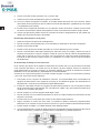
MANUAL DE INSTRUCCIONES
SISTEMA PUNTO CERO
SERVICE MANUAL
ZERO POINT SYSTEM
C
E

4
MANUAL DE SERVICIO
1.- Generalidades
1.1 Acerca de este manual.
Esta guía permite el uso seguro y efi ciente del 0-MAK que usted ha adquirido.
Este manual forma parte del dispositivo de sujeción y debe mantenerse accesible para el personal
que lo vaya a utilizar en cualquier momento y en las proximidades del puesto de trabajo.
Es necesario leer y entender este manual antes de comenzar cualquier trabajo con el 0-MAK,
especialmente las indicaciones relativas a la seguridad en su uso.
Para realizar un trabajo seguro hay que asegurarse que se cumplen todas las indicaciones que
aparecen en este manual.
Las instrucciones de este manual se proporcionan para la compresión básica del 0-MAK que puede
diferir del diseño real del producto.
No se asume ninguna responsabilidad por daños resultantes derivados de la falta de observación y
cumplimiento de lo indicado en este manual de instrucciones.
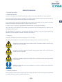
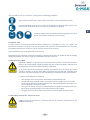
1.2 Símbolos.
Las directrices de seguridad se explican mediante símbolos.
Las instrucciones de seguridad van acompañadas por palabras de advertencia, que expresan el grado
de riesgo.
Indica una situación inminentemente peligrosa que puede conducir a la muerte o
lesiones graves, sino se evitan los riesgos.
Indica una situación potencialmente peligrosa que puede conducir a la muerte o
lesiones graves, sino se evitan los riesgos.
Indica una situación potencialmente peligrosa que puede conducir a lesiones leves,
sino se evitan los riesgos.
Destacados consejos útiles, información y recomendaciones para un efi ciente y sin
problemas, uso del 0-MAK.
1.3 Limitaciones de responsabilidad.
Toda la información e instrucciones de este manual están de acuerdo con las normas y reglamentos
aplicables a los 0-MAK defi nidos estos como “cuasi máquinas”.

5
Estas normas son:
• Directiva 2006/42/CE
• DIN EN ISO 12100: 2010 Seguridad de las máquinas - Principios generales para el diseño para
la evaluación de riesgos y reducción de riesgos.
• DIN EN ISO 4414: 2010 Energía en fl uidos neumáticos - Normativa general y requisitos de
seguridad para los sistemas y sus componentes.
• DIN EN ISO 14121-2008. Seguridad en las máquinas.
El fabricante no asume ninguna responsabilidad por los daños debidos a:
• Que no se sigan las instrucciones de este manual.
• Que se haga uso indebido del 0-MAK y sus accesorios.
• Que el personal que use el producto no esté capacitado.
• Que se realicen cambios técnicos no autorizados en el 0-MAK.
• Que se utilicen piezas de repuesto no autorizadas.
2.- Seguridad
2.1 Personal cualifi cado
Riesgo de lesiones debido a la insufi ciente cualifi cación del personal.
Solo personal cualifi cado y especializado para ello, puede instalar, mantener, o
desinstalar el 0-MAK.
La responsabilidad del uso, mantenimiento y reparación del 0-MAK debe estar
claramente especifi cada.
2.2 Requerimiento de personal
Especialista es la persona que por su formación técnica, su experiencia y su conocimiento práctico
es capaz de evaluar el trabajo a realizar, reconocer los peligros potenciales y de tomar decisiones al
respecto.
Durante el proceso de instrucción de los usuarios solo se les debe permitir trabajar con el 0-MAK si
esta delante un especialista.
Es conveniente que todas las actividades relacionadas con este 0-MAK sean supervisadas previamente
por personal responsable de la empresa y en su caso por un responsable en hidráulica o neumática.
El operador del 0-MAK está sujeto a las obligaciones legales de seguridad del trabajo, prevención de
accidentes y normas de protección ambiental que rijan en este sector de la industria.
2.3 Uso previsto
El 0-MAK es considerado por la Directiva 2006/42/CE como una “cuasi máquina” .Esta consideración
es debida a que está diseñado para colocarse en una máquina herramienta determinada. El 0-MAK
dentro de la máquina debe servir solo como un elemento de sujeción de piezas para ser mecanizadas.
El 0-MAK es un amarre estático, no está diseñado para ser usado en máquinas rotativas tipo torno
o similar.
El llamado “uso previsto” también incluye el cumplimiento de todas las especifi caciones
de este manual. Algo diferente al “uso previsto o uso diferente del 0-MAK se considera
uso indebido y puede llevar a situaciones peligrosas.
En particular cuando se utilizan en maquinas –herramientas con otros datos y
condiciones técnicas diferentes a las habituales.
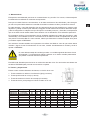
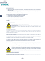
2.4 Equipo de protección personal
En el trabajo con estos 0-MAKs se debe utilizar el equipo de protección necesario para garantizar y
reducir al mínimo los riesgos de salud del operario.

6
El equipo de trabajo debe cumplir como mínimo con las siguientes pautas:
La ropa de trabajo debe ser una ropa ajustada. Debe servir para evitar lesiones de
atrapamiento.
Se debe utilizar calzado de seguridad que tengan las protecciones para evitar lesiones
por caída de piezas. Las suelas de estos zapatos deben ser antideslizantes para evitar
caídas por resbalón.
Dentro del equipo de trabajo deben estar incluidas gafas
de protección, así como guantes y en su caso si fuera
necesario el uso del casco.
2.5 Riesgos especiales
En la normativa de salud laboral de cada país existe la obligatoriedad de realizar una valoración de
riesgos laborales de cada puesto de trabajo. De las conclusiones que de ella se deriven se deberán
tomar las medidas de prevención necesarias para evitar cualquier tipo de riesgo no habitual
Estas medidas pueden no estar refl ejadas en este manual.
El respeto de estas medidas por el operario llevará a reducir riesgos para la salud del mismo así como
para evitar situaciones peligrosas para otras personas, las instalaciones y las máquinas.
2.6 Manipulación con el 0-MAK
Los 0-MAKs utilizados de forma individual no presentan graves riesgos de manipulación,
pero cuando se colocan varios en placas para su utilización el peso aumenta y su
manipulación debe estar sometida a las normativas de salud laboral que hay que
cumplir obligatoriamente.
En todo momento se debe recurrir al uso de mecanismos mecánicos de manipulación
como grúas y polipastos. Para ello los 0-MAKs en placa van provistos de tapones
roscados donde se pueden colocar los cáncamos necesarios para su manipulación
por medios mecánicos.
Para evitar las situaciones peligrosas:
• El operador no debe situarse nunca debajo de la carga.
• Las eslingas que se utilicen, deben ser las indicadas según el peso a desplazar.
• Las eslingas marcadas para un solo uso, deben ser retiradas después de usadas
• No utilizar nunca eslingas agrietadas o en mal estado de conservación.
• Hay que buscar siempre la situación del centro de gravedad de la pieza antes de
comenzar su desplazamiento.
• Hay que evitar los golpes con las partes sobresalientes de la máquina.
• Hay que usar gafas para evitar proyecciones del sistema de limpieza del 0-MAK
2.7 Instrucciones para el montaje. Pruebas funcionales
Los 0-MAKs no se podrán montar en una máquina que no cumpla los requisitos que
marca la directiva 2006/42/CE.

7
Riesgo de lesiones por movimiento de los componentes. Riesgo de atrapamiento.
Al instalar un 0-MAK en una máquina y antes de ponerlo en marcha se debe comprobar
su correcto funcionamiento por un especialista que revisará:
• Que desamarra correctamente con una presión mínima de 6bar.
• Que amarra correctamente al quitar la presión de suministro.
• Que no hay pérdidas del fl uido del suministrado.
• Que el orifi cio del 0-MAK donde tiene que introducirse el tirante está libre de todo
tipo de suciedad.
Además hay que tener en cuenta que las bolas del 0-MAK son móviles y tienen un
recorrido automático, lo que posibilita un peligro de atrapamiento. El atrapamiento
puede producir lesiones graves. Bajo ninguna circunstancia hay que introducir ningún
elemento en el orifi cio central del 0-MAK que no sea el tirante cuando se va a proceder
a abrir o cerrar el mismo.
El funcionamiento de la máquina donde se monta el 0-MAK tiene que impedir que el
operario pueda tener sus manos en la zona de trabajo mientras que haya posibilidad
de que el 0-MAK este en movimiento. Para ello se colocaran barreras físicas como
puertas o zonas sin paso.
Durante las operaciones de apertura y cierre del 0-MAK, el operario no podrá acceder
a la zona donde esté colocado el 0-MAK ni a los utillajes que estén amarrándose sobre
los mismos.
Durante el tiempo que el 0-MAK esté abierto, cuando se proceda a la extracción o
inserción del (utillaje, pallet, etc.) en el 0-MAK hay que asegurar que las partes móviles
(pallet, mordaza, pieza, etc. que tenga colocados los tirantes) hayan llegado a su
posición fi nal haciendo contacto con la cara plana de la tapa del 0-MAK, en el caso de
la inserción. Posteriormente, se accionaría el cierre del 0-MAK.
Riesgo de lesiones debido a la incorrecta sujeción de la pieza
Una presión de alimentación del fl uido demasiado baja (por debajo de 6bar) puede
producir una incorrecta apertura del 0-MAK. Ante la duda de baja presión de
alimentación o fuga, bajo ningún concepto tirar del objeto amarrado (pallet, mordaza,
pieza, etc.) con elementos de gran poder como puede ser un polipasto, puente grúa,
etc. ya que puede haber grave riesgo de rotura, producir proyecciones y dar como
resultado lesiones graves
Se debe comprobar periódicamente la presión de suministro del aire, la lubricación
del mismo, el estado de las mangueras de alimentación, así como la apertura y cierre
correcto del 0-MAK.
2.8 Fallos
Si se produce un fallo en el 0-MAK que pueda poner en peligro la seguridad o se
sospecha que puede que la situación del mismo pueda ser un problema debido a las
características de la producción, la máquina en la que va montado el 0-MAK debe ser
inmediatamente retenida y permanecer cerrada hasta que el fallo haya sido localizado.
2.9 Fluidos utilizados
Hay que comprobar que los usuarios no tengan relaciones alérgicas al contacto con
la piel con la grasa de lubrifi cación, ni con el aceite que lubrica el aire de alimentación
que se utilizan en el 0-MAK para su funcionamiento habitual.
Para evitar estos riesgos es recomendable el uso de guantes.

8
SISTEMA DE PUNTO CERO 0-MAK
A.- Funcionamiento y puesta en marcha.
Este sistema de punto cero 0-MAK de Fresmak es de simple efecto. El amarre es mecánico por medio
de muelles y el desamarre funciona con alimentación de aire comprimido a una presión superior a 6Bar
e inferior a 10Bar. Este aire debe suministrase lubrifi cado y libre de agua: por ello es imprescindible
instalar a la entrada del 0-MAK un sistema de fi ltro y lubrifi cación del aire.
Se suministra en diferentes tamaños y en dos versiones distintas, en función de si se quiere utilizar de
forma unitaria (con chaveteros) o utilizando dos o más unidades (sin chavetero)
Se pueden suministrar los dispositivos por separado o montados en placa. En caso de ser suministrados
por separado, seguir las instrucciones de las páginas 9, 10 y 11 para su instalación.
Los dispositivos tienen un sistema de limpieza incorporado (soplido) del que se puede hacer uso o no
en función de las necesidades. Se recomienda usarlo en todo momento a no ser que exista alguna
limitación en el proceso. Para ponerlo o quitarlo es sufi ciente con sustituir los tres prisioneros que se
sitúan en el fondo del dispositivo. ((296022010) con soplido y el (296023010) sin soplido).
Cuando se le suministra aire al dispositivo, el soplido se activará de manera automática. Cuando se
trabaje con soplido, para que el dispositivo funcione de forma correcta, el caudal de entrada del aire
comprimido deberá ser como mínimo de 2.5 l/s (tubo de Øint=6) por cada placa de 4 dispositivos en
funcionamiento al mismo tiempo.
B.- Datos tecnicos.
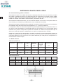
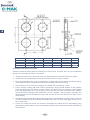
Tabla de caracteristicas:
Referencia Chaveteros Fuerza de
tiro
Fuerza de
retención
Presión
de trabajo
mínima
Repetibilidad Peso
(kN) (kN) (bar) mm Kg
260000010 - 10 25 6 0.005 1.1
261000010 4x90º 10 25 6 0.005 1.1
260000020 - 20 55 6 0.005 2.4
261000020 4x90º 20 55 6 0.005 2.4
Tabla de dimensiones:
Referencia ØA B C ØD ØE F G
260000010 112 25 10 78 92 8xM6 -
261000010 112 25 10 78 92 8xM6 10H7
260000020 138 36 10 108 120 8xM6 -
261000020 138 36 10 108 120 8xM6 10H7

9
C- Mantenimiento.
El dispositivo está diseñado para tener un mantenimiento muy sencillo. Por lo tanto, el desmontaje de
la unidad sólo se realizará en ocasiones excepcionales.
Para que el 0-MAK funcione correctamente, se le debe suministrar el aire lubrifi cado y libre de agua:
por ello es imprescindible instalar a la entrada del 0-MAK un sistema de fi ltro y lubrifi cación del aire.
En cada apertura y cierre del dispositivo hay que asegurarse de que las superfi cies en contacto entre
dispositivo y utillaje están limpias. Además, el agujero central donde entra el tirante debe estar limpio
y libre de refrigerante o cualquier otro tipo de líquido o suciedad (viruta, etc.). Para ello, los dispositivos
que no se estén siendo usados deben estar cubiertos con los tirantes de cierre existentes para tal fín.
Es importante verifi car el funcionamiento de las unidades regularmente (cada dos semanas o cada
1000 atadas). Las unidades funcionan correctamente si las bolas se retiran completamente al aplicar
una presión mínima de 6Bar. En caso contrario, habría que desmontar la unidad completa de la placa
y enviarla a reparar a FRESMAK.
Las revisiones visuales también son importantes. No utilizar el 0-MAK en caso de que existan daños
visuales o signos de mal funcionamiento. En tal caso, sustituir inmediatamente la unidad y enviar a
reparar a FRESMAK.
En caso de desmontaje de la unidad, proceder con cuidado siguiendo las instrucciones
del apartado F. Los dispositivos 0-MAK contienen en su interior muelles pretensados
que pueden ocasionar lesiones importantes.
El 0-MAK está diseñado para funcionar un máximo de 500.000 ciclos. Por encima de esto deberá ser
enviado a FRESMAK para proceder a una revisión completa.
D. Tirantes y alojamientos.
Existen cuatro modelos diferentes de tirantes, en función de su uso.
1. Tirante centrador en toda su circunferencia (2jes) (2 ranuras)
2. Tirante posicionador en un eje (1 ranura)
3. Tirante de amarre sin función de centraje (sin ranuras)
4. Tirante de cierre, para proteger el cilindro cuando no se usa.
Referencia Tipo ØA B C H ØD E Sw Hs/Hm
296004010 Centrador 22 31 4 4.5 15 M8 8 10
296005010 Posicionador 22 31 4 4.5 15 M8 8 10
296006010 Amarre 21.7 31 4 4.5 15 M8 8 10
296007010 Cierre 21.8 28.5 - - M8 -
296004020 Centrador 32 40.6 5 5.5 25 M12 10 15
296005020 Posicionador 32 40.6 5 5.5 25 M12 10 15
296006020 Amarre 31.7 40.6 5 5.5 25 M12 10 15
296007020 Cierre 31.8 37.6 - 5.5 - M12 - 15

10
Tamaño Montaje Referencia Tornillo superior Peso kg.
MAK 10 Inferior 905210090 M6x35 0.01
Superior M8*
MAK 20 Inferior 996040125 M10x45 0.04
Superior M12*
*La longitud del tornillo depende del montaje del usuario, siempre respetando la cota Hm.
Es recomendable usar la opción del tornillo superior, siempre que sea posible
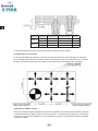
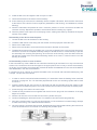
E. Disposición de los tirantes
En el siguiente dibujo se puede ver cuál sería el posicionamiento típico de los tirantes en una placa
de 6 x 0-MAK. Para una placa con distinto número de tirantes el criterio de colocación sería el mismo,
quitando o poniendo más tirantes de amarre en función del numéro de puntos cero colocados.
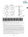
F. Montaje de 0-MAK en placa.
En el caso de haber adquirido dispositivos 0-MAK por separado, es necesario tener una base o soporte
para poder insertar el 0-MAK y hacerlo funcionar. Para ello, a continuación se puede ver en el dibujo de
lo que sería una placa de 4x0-MAK con los alojamientos y agujeros necesarios para poder ensamblar
y utilizar el 0-MAK.

11
ØD H ØDc Hc ØHs T
260000010 78 25 7.5 21.25 92 G1/8”
261000010 78 25 7.5 21.25 92 G1/8”
260000020 108 36 12 30 120 G1/4”
261000020 108 36 12 30 120 G1/4”
Montaje del dispositivo en placa:
Desembalar el dispositivo con cuidado sin soltar el tornillo central, ya que éste sujeta los muelles
interiores que están precomprimidos. El procedimiento de montaje es el siguiente:
1. Engrasar la superfi cie de los alojamientos de la placa mecanizada con grasa convencional de
máquina.
2. Engrasar la parte cilíndrica exterior del dispositivo donde se ven las dos juntas tóricas.
3. Colocar la junta pequeña de Ø8x1 (viene separada en bolsa de plástico) en el alojamiento que
tiene el dispositivo en la cara inferior. Ponerle grasa para evitar que se caiga en el montaje.
4. Presentar el dispositivo en el alojamiento, lo más alineado posible con los tornillos de amarre.
5. Empujarlo de manera recta presionando con las dos manos de manera simétrica, teniendo especial
atención en el paso de las juntas tóricas por la entrada del alojamiento. El dispositivo debe entrar
con la mano casi hasta el fi nal (hasta que falten 10mm aprox.). En el caso de que se cruce y no
entre, se puede usar una maceta de plástico para enderezarlo pero dándolo golpecitos suaves.
Una vez esté derecho debemos seguir empujando con la mano. Nunca se debe meter el dispositivo
forzándolo dándole con la maceta ya que se podrían romper las juntas tóricas o incluso griparlo.
6. La última parte se debe meter ayudándose de los tornillos de M6 que vienen separados, roscándolos
en cruz de manera que el 0-MAK se mantenga lo más horizontal posible hasta hacer tope. Una vez
hecho tope, aplicar un par de 10Nm a cada tornillo.
7. Soltar el tornillo central de M6 y retirarlo junto con la arandela y el tapón sujección de bolas
(poliexpan) que se encuentra en el interior del agujero. Es importante guardar estos componentes,
para poder realizar el mantenimiento de los dispositivos más adelante.

12
8. Colocar el tornillo de M4 y apretarlo con un par de 4Nm.
9. Verifi car que las bolas del dispositivo giran sin problemas.
10. Si se va a utilizar la limpieza con soplido, el montaje estaría terminado. En caso contrario, habría
que sustituir los tres prisioneros que se sitúan en el fondo del dispositivo. ((296022010) con soplido
y el (296023010) sin soplido).
11. Introducir aire comprimido lubrifi cado con una presión mínima de 6 bares. Verifi car que las bolas
se retiran correctamente. Repetir esta operación varias veces antes de introducir ningún tirante.
12. Colocar los tapones de plástico sobre los 8 tornillos de amarre, asegurándose de que quedan por
debajo de la superfi cie de apoyo del 0-MAK.
Desmontaje del dispositivo de la placa:
1. Soltar el tornillo de M4 del fondo del alojamiento.
2. Roscar el tornillo central de M6 junto con la arandela y el poliexpan en el interior del agujero.
3. Extraer los 8 tornillos de M6.
4. Extraer los dos prisioneros de M6 que están en el mismo diámetro que los tornillos.
5. Roscar 2 tornillos M6 lo más largos posible (min 20mm de rosca) en la tapa y usarlos a modo de
extractor para extraer el conjunto completo. Tratar de roscar los dos de manera compensada para
evitar que el conjunto se cruce y se atore. Una vez extraído el cuello de la tapa del alojamiento,
tirando de los dos tornillos al mismo tiempo con cuidado de no cruzarlo, sale en conjunto completo
del alojamiento.
G. Desmontaje de utillaje en caso de avería:
En el caso de que alguno de los 0-MAK no desamarre al introducir aire y no haya manera de acceder
a los 8 tornillos del mismo o al tornillo que une el tirante a la placa superior, existe una manera de
poder desbloquear el conjunto. Para ello, es necesario adquirir el conjunto de desamarre mecánico
286000010 en el caso del MAK10 y 286000020 en el caso del MAK20.
Consiste en un conjunto de 3 piezas. Un tornillo roscado completo, un tapón con rosca interior y exterior
y una cuña. El proceso sería el siguiente:
1. Para poder usar el conjunto de desamarre mecánico, es imprescindible tener mecanizados los
agujeros de alimentación como aparecen en la pág. 9. Se utilizará el agujero de alimentación H7
perpendicular al cilindro que no desamarra para desbloquearlo.
2. Insertar la cuña hasta el fondo en el agujero de alimentación lateral H7 con la cara plana mirando
hacia la superfi cie de la placa donde van colocados los 0-MAK. Hay que introducirlo hasta hacer
contacto con el embolo del 0-MAK.
3. Roscar el tapón en el mismo agujero hasta llegar a tope.
4. Roscar el tornillo con rosca total suministrado con el kit en el tapón hasta que la resistencia de este
empiece a aumentar.
5. Introducir aire en el circuito para que el resto de los cilindros estén abiertos.
6. Seguir roscando el tornillo de rosca total; la resistencia debería aumentar progresivamente.
Detenerse en el momento en que se note un tope físico o que la resistencia aumenta bruscamente.
7. Intentar extraer el utillaje. Los 0-MAK deberían estar desbloqueados.
8. Una vez desbloqueado y sacado el utillaje, desmontar el 0-MAK bloqueado siguiendo la instrucciones
de esta misma hoja, y enviarlo a Fresmak para su comprobación y posible reparación.

13
SERVICE MANUAL
1.- General information
1.1 About this manual
The aim of this guide is to facilitate the safe and effi cient use of the 0-Mak that you have adquired.
This manual is part of the security regulatory and must be made available to all personnel who will use
it at any moment and maintained in the vicinity of the workplace.
It is a requirement to read and comprehend this manual before undertaking any job using the clamping
0-Mak, especially the indications relating to safety while it is in use.
In order to carry out safe work all indications outlined in this manual must be followed.
The instructions in this manual provide a basic comprehension of the 0-Mak which may diff er from the
real design of the product.
No responsibility is assumed for consequential damages resulting in the lack of observation and
adherence to the indications outlined in this instruction manual.
1.2 Symbols
The safety guidelines are explained through the use of symbols.
The safety instructions are accompanied by words of warning, which indicate the level of risk.
Indicates an imminently dangerous situation which could lead to death or serious injury
should risks not be avoided.
Indicates a potentially dangerous situation which could lead to death or serious injury
should risks not be avoided
Indicates a potentially dangerous situation which could lead to minor injury should risks
not be avoided.
Helpful tips, information and recommendations to ensure an effi cient and problem-free
use of the 0-Mak
1.3 Liability limitations.
All information and instructions in this manual are in agreement with the rules and regulations applicable
to 0-Maks defi ned as “partly completed machinery”.

14
These regulations are:
Directive 2006/42/CE
• DIN EN ISO 12100: 2010 Safety of machinery - General design principles in order to evaluate risks
and reduce risks.
• DIN EN ISO 4414: 2010 Energy in fl uid pneumatics - General regulations and security requirements
for the systems and their components.
• DIN EN ISO 14121-2008. Safety in machinery.
The manufacturer assumes no responsibility for damage due to:
• Not following the instructions outlined in this manual.
• Improper use of the 0-Mak and its accessories.
• Use of the product by untrained personnel.
• Unauthorised technical alterations made to the 0-Mak.
• The use of unauthorised replacement parts.
2. Safety.
2.1 Qualifi ed Personnel
Risk of injury due to insuffi cient training of personnel.
Only qualifi ed and specialised personnel may install, carry out maintenance on or
uninstall the 0-Mak.
Responsibility for the use, maintenance and repair of the 0-Mak should be clearly
specifi ed.
2.2. Labour requirements.
A specialist is the person who, due to his technical training, experience and practical knowledge is
capable of evaluating the work required, recognising potential risks and danger and making the
necessary decisions in response.
Whilst users are undergoing the instructional process they should only be allowed to work with the
0-Mak if a specialist is present.
It is advisable that all activities relating to this 0-Mak be previously supervised by the company’s
managerial staff and, where appropriate, by a hydraulics or pneumatics manager.
The operator of the 0-Mak is subject to the legal obligations of work safety, accident prevention and
regulations regarding environmental protection applicable to this sector of the industry.
2.3 Intended use.
The 0-Mak is considered by Directive 2006/42/CE to be a “partly completed machinery”. This consideration
is due to the fact that it is designed to be attached to a determined machine tool. The 0-Mak inside the
machine should only serve as a clamping element for workpieces to be machined. The 0-Mak is a static
clamp, it is not designed to be used with rotary machines such as lathes or similar.
The section “intended use” also includes the compliance of all of the specifi cations in this
manual. Anything other than “intended use” or any other use of the 0-Mak is considered
to be improper use and could lead to dangerous situations.
Particularly when used in machines - tools with other details or technical conditions that
diff er from the standard.
2.4 Personal Protective Equipment.
When working with these 0-Maks the necessary protective equipment must be used in order to guarantee
and reduce health risks to the operator to a minimum.

15
The work team must, as a minimum, comply with the following guidelines:
Tight clothing must be worn. Said clothing must help to avoid entrapment injuries.
Protective footwear must be worn in order to avoid injuries caused by falling pieces. The
soles of said footwear must be non-slip to avoid falls due to slipping.
The work equipment must include protection goggles, as well as
gloves and helmets should they be necessary.
2.5 Special risks.
In every country’s professional health and safety regulations it is obligatory to carry out a labour risk
assessment for every work post. From the conclusions that arise from said assessment the necessary
preventative measures to avoid any type of unusual risk are to be enforced
These measures may not be refl ected in this manual.
Respecting these measures will help the operator to reduce risks to their own health as well as avoiding
dangerous situations for other people, the installations and the machines.
2.6 Handling the 0-Mak.
Individual 0-Mak do not present serious handling risks but when several are placed on
plates to be used together weight increases and they must be handled in adherence to
the obligatory professional health and safety regulations.
At all times, the use of mechanical handling mechanisms such as cranes and hoists
should be applied. To do this, the 0-Maks on the plate are provided with threaded plugs
where the eye bolts necessary for their handling by mechanical means can be placed.
In order to avoid dangerous situations:
• The operator must never position themselves underneath the load.
• Designated slings must be used in accordance with the weight that is to be lifted.
• Single-use slings are to be discarded after use. Slings that appear to be broken or in
poor condition are never to be used.
• The centre of gravity of the piece must always be found before initiating movement..
• Blows to the protruding edges of the machine are to be avoided.
• Goggles must be used to prevent projections from the 0-Mak cleaning system.
2.7 Assembly instructions. Functional tests
0-Maks cannot be mounted on a machine that fails to meet the requirements of the
2006/42/CE directive.

16
Risk of injury from movement of components. Risk of entrapment.
When installing 0-Mak onto a machine and before putting it into operation a specialist
must verify that it is in working order. They will check:
• It is unlocked correctly with a minimum pressure of 6 bar.
• It is fastened correctly when removing supply pressure.
• There are no losses of the supplied fl uid.
• The hole of the 0-Mak where the nipple must be inserted is free of all kinds of dirt.
Additionally, it must be considered that the 0-Mak balls are mobile and have an automatic
path, which makes it possible to trap them. Entrapment may cause serious injury. Under
no circumstances should any component be inserted into the central hole of the 0-Mak
other than the nipple when it is to be opened or closed.
The operation of the machine where the 0-Mak is mounted must prevent the operator
from having their hands in the work area while there is a possibility that the 0-Mak is in
motion. To this end, physical barriers such as doors or non-passage areas should be
placed.
During the opening and closing operations of the 0-Mak, the operator will not be able to
access the area where the 0-Mak is placed or the tools that are being fastened to them.
During the time when the 0-Mak is open, when the extraction or insertion of the tooling,
pallet, etc. is carried out in the 0-Mak, it must be ensured that the moving parts (pallet,
clamp, piece, etc. that are in place with nipples) have reached their fi nal position,
contacting the fl at surface of the 0-Mak cover, in the case of insertion. Subsequently, the
closure of the 0-Mak should be triggered.
Risk of injury due to incorrect clamping of the part
Excessively low fl uid supply pressure (below 6 bar) may cause the 0-Mak to open
incorrectly. When in doubt about low supply pressure or leakage, under no circumstances
pull the fastened object (pallet, clamp, piece, etc.) with highly powerful components such
as hoists, overhead cranes, etc., as there may be a serious risk of breakage, causing
projections and resulting in serious injury.
The air supply pressure, lubrication, condition of the supply hoses, and the correct
opening and closing of the 0-Mak must be checked periodically
2.8 failures
If a failure occurs in the 0-Mak that could endanger safety or if there is suspicion that
the situation of the 0-Mak may be a problem due to the characteristics of the production,
the machine in which the 0-Mak is mounted it must be immediately withheld and remain
closed until the fault has been located.
2.9 Fluids used.
It must be verifi ed that users do not have allergic relations to skin contact with the
lubricating grease or with the oil that lubricates the supply air used in the 0-Mak for its
normal operation.
To avoid these risks, the use of gloves is recommended.

17
0-MAK ZERO-POINT SYSTEM
A. Operation and start-up
This Fresmak 0-MAK zero-point system has a single-acting operation. Fastening is mechanical by
means of springs and unfastening works with compressed air supply at a pressure greater than 6
bar and less than 10 bar. This air must be supplied lubricated and free of water. For this reason, it is
essential to install an air lubrication and fi lter system at the 0-MAK inlet.
It is supplied in diff erent sizes and in two diff erent versions, depending on whether the user wishes to
use it individually (with keyways) or using two or more units (without keyways).
Devices can be supplied separately or mounted on the plate. If supplied separately, follow the instructions
on pages 20, 21 and 22 for installation.
The devices have a built-in cleaning system (blow cleaning), which can be used or not depending on
the needs. It is advisable to use it at all times unless there is some limitation in the process. To apply it
or remove it, replace the three studs located at the bottom of the device. (296022010, with blowing, and
296023010, without blowing).
When air is supplied to the device, the air blowing will automatically be activated. When working with air
blowing, for the device to operate correctly, the infl ow rate of the compressed air must be at least 2.5 l/s
(tube with Øint = 6) for each plate with 4 devices operating at the same time.
B. Technical data
Features table
Code Keynuts Holding
power
Retaining
power
Working
pressure Repeatability Weight
(kN) (kN) (bar) mm Kg
260000010 - 10 25 6 0.005 1.1
261000010 4x90º 10 25 6 0.005 1.1
260000020 - 20 55 6 0.005 2.4
261000020 4x90º 20 55 6 0.005 2.4
Dimesion table:
Code ØA B C ØD ØE F G
260000010 112 25 10 78 92 8xM6 -
261000010 112 25 10 78 92 8xM6 10H7
260000020 138 36 10 108 120 8xM6 -
261000020 138 36 10 108 120 8xM6 10H7

18
C.- Maintenance.
The device is designed for very easy maintenance. Therefore, disassembling the unit will only be done
on rare occasions.
In order for the 0-Mak to operate properly, it must be supplied with water-free and lubricated air. For this
reason, it is essential to install an air fi lter and lubrication system at the 0-MAK inlet.
At each opening and closing of the device, it must be ensured that the surfaces in contact between the
device and the tools are clean. In addition, the central hole where the nipple is inserted must be clean
and free of refrigerant or any other type of liquid or dirt (shavings, etc.). To do this, the devices that are
not being used must be covered with the existing closure nipples for this purpose.
It is important to check the operation of the units regularly (every two weeks or every 1000 fastenings).
The units operate correctly if the balls are completely removed by applying a minimum pressure of 6
bar. Otherwise, the complete unit would have to be removed from the board and sent to FRESMAK for
repair.
Visual reviews are also important. Do not use the 0-Mak in case of visual damage or signs of malfunction.
In this case, immediately replace the unit and send it to FRESMAK for repair.
If the unit is disassembled, proceed carefully following the instructions in section F. The
0-Mak devices contain pre-tensioned springs that may cause serious injuries.
The 0-MAK is designed to run a maximum of 500,000 cycles. Above this, it must be sent to FRESMAK
for a complete review.
D. Nipples and housings.
There are four diff erent nipple models, depending on their use.
1. Centering nipple around the entire circumference (2x) (2 slots)
2. Positioning nipple on one axle (1 slot)
3. Locking nipple, without centering function (without slots)
4. Protecting nipple, to protect the cylinder when not in use.
Code Type ØA B C H ØD E Sw Hs/Hm
296004010 Centering 22 31 4 4.5 15 M8 8 10
296005010 Positioning 22 31 4 4.5 15 M8 8 10
296006010 Locking 21.7 31 4 4.5 15 M8 8 10
296007010 Protecting 21.8 28.5 - - M8 -
296004020 Centering 32 40.6 5 5.5 25 M12 10 15
296005020 Positioning 32 40.6 5 5.5 25 M12 10 15
296006020 Locking 31.7 40.6 5 5.5 25 M12 10 15
296007020 Protecting 31.8 37.6 - 5.5 - M12 - 15

19
.
Size Set up Code Top screw Weight kg.
MAK 10 Lower 905210090 M6x35 0.01
Upper M8*
MAK 20 Lower 996040125 M10x45 0.04
Upper M12*
* The length of the screw depends on the assembly of the user, always respecting the Hm dimension.
It is advisable to use the top screw option, where possible.
E. Arrangement of the nipples
The following drawing shows the typical positioning of the nipples on a 6 x 0-Mak plate. For a plate with a
diff erent number of nipples, the placement criteria would be the same, with more nipples being removed
or added depending on the number of zero points placed.
F. Assembly of the 0-Mak on the plate:
In the case the purchasing 0-Mak devices separately, it is necessary to have a base or support to insert
the 0-Mak and activate it. For this purpose, the following drawing shows a 4x0-Mak board with the
housings and holes necessary to assemble and use the 0-Mak.

20
ØD H ØDc Hc ØHs T
260000010 78 25 7.5 21.25 92 G1/8”
261000010 78 25 7.5 21.25 92 G1/8”
260000020 108 36 12 30 120 G1/4”
261000020 108 36 12 30 120
G1/4”
G1/4”
Assembly of the device on a plate:
Carefully unpack the device without loosening the central screw, as it fi xes the inner pre-compressed
springs. The assembly procedure is as follows:
1. Grease the surface of the housings of the machined plate with conventional machine grease.
2. Grease the outer cylindrical part of the device where the two O-rings are visible.
3. Place the small Ø8x1 joint (it comes separately in a plastic bag) in the housing that has the device
on the bottom surface. Add grease to prevent it from falling off in the assembly.
4. Place the device in the housing, as aligned as possible with the clamping screws.
5. Push it straight, pressing with both hands symmetrically, paying special attention to the passage
of the O-rings through the entrance of the housing. The device must be inserted by hand almost
to the end (until approx.10 mm are missing). In the event that it crosses and fails to enter, a plastic
pot can be used to straighten with gentle taps. Once it is straight, continue pushing manually. The
device should never be inserted by forcing it with a mallet as this could break the O-rings or even
cause seizing.
6. The last part must be inserted using the M6 screws that come separately, by tapping them crosswise
so that the 0-Mak is kept as horizontal as possible until it stops. Once it stops, apply a torque of 10
Nm to each screw.
7. Loosen the central M6 screw and remove it alongside the washer and the ball-retaining plug
(polyexpan) located inside the hole. It is important to keep these components for later maintenance
of the devices.

21
8. Install the M4 screw and tighten it with a torque of 4 Nm.
9. Check that the balls of the device rotate smoothly.
10. If blow cleaning is to be used, the assembly will be complete. Otherwise, the three allen set screws
at the bottom of the device must be replaced. (296022010, with blowing, and 296023010, without
blowing)
11. Introduce lubricated compressed air with a minimum pressure of 6 bar. Check that the balls are
removed correctly. Repeat this operation several times before inserting any nipples.
12. Place the plastic screw caps on the 8 clamping screws, making sure that they are below the support
surface of the 0-Mak.
Disassembly of the device from the plate:
1. Loosen the M4 screw at the bottom of the housing.
2. Thread the M6 central screw along with the washer and the polyexpan inside the hole.
3. Remove the 8 M6 screws.
4. Remove the two M6 allen set screws that are the same diameter as the screws.
5. Thread 2 M6 screws as long as possible (min. of 20 mm of thread) in the cover and use them as an
extractor to remove the complete assembly. Attempt to thread the two in a balanced way to prevent
the assembly from crossing and jamming. Once the neck of the housing cover has been removed,
pull the two screws at the same time while being careful not to cross it. It should comes out of the
housing as a whole.
G. Disassembly of tools in case of failure:
In the event that any of the 0-Maks do not untie when introducing air and there is no way to access its 8
screws or the screw that connects the nipple to the upper plate, there is a way to unlock the assembly.
To do this, it is necessary to purchase the mechanical release set 286000010 in the case of the MAK10
and 286000020 in the case of the MAK20.
It consists of a set of 3 pieces. A complete threaded screw, an internal and external threaded plug, and
a wedge. The process is as follows:
1. In order to use the mechanical release assembly, it is essential to have the feeding holes machined
as shown on page 20. The H7 feed hole perpendicular to the non-unlocking cylinder will be used
to unlock it.
2. Insert the wedge all the way into the H7 side feed hole with the fl at side facing the surface of the
plate where the 0-Maks are placed. It must be inserted until it makes contact with the 0-Mak piston.
3. Screw the plug in the same hole until it stops.
4. Thread the fully threaded screw supplied with the kit into the plug until the resistance of the plug
begins to increase.
5. Introduce air into the circuit so that the rest of the cylinders are open.
6. Continue threading the full thread screw. The resistance should increase progressively.
7. Stop at the moment when you notice a physical stop or if the resistance increases sharply. Attempt
to extract the tooling. The 0-Mak should be unlocked.
8. Once the tooling is unlocked and removed, disassemble the locked 0-Mak following the instructions
on this sheet and send it to Fresmak for checking and possible repair.

2222
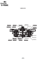
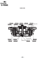
260000010

23
MAK10
MAK10
REF DENOMINACION DENOMINATION
1 296001010 TAPA CAP
2 296002010 EMBOLO PISTON
3 296003010 RETENEDOR RETAINER
4 296015010 TAPÓN TORNILLOS 0-MAK SCREW CAP
5 296022010 PRISIONERO CON AGUJERO ALLEN SET SCREW WITH HOLE
6 296028010 TAPON SUJECION BOLAS BALL STOPPER
7 296029010 ARANDELA WASHER
8 296008010 BOLA ACERO BALL
9 296009010 MUELLE SPRING
10 296010010 JUNTA TORICA O-RING
11 296011010 JUNTA TORICA O-RING
12 296012010 JUNTA TORICA O-RING
13 296013010 JUNTA TORICA O-RING
14 296014010 PRISIONERO SCREW
15 296019010 TORNILLO SCREW
16 296021010 TORNILLO SCREW
17 296023010 PRISIONERO ALLEN SET SCREW
18 912810125 TORNILLO SCREW

2424
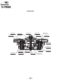
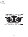
261000010

25
MAK10 CON CHAVETEROS
MAK10 WITH KEYNUTS
REF DENOMINACION DENOMINATION
1 296101010 TAPA CAP
2 296002010 EMBOLO PISTON
3 296003010 RETENEDOR RETAINER
4 296015010 TAPÓN TORNILLOS 0-MAK SCREW CAP
5 296022010 PRISIONERO CON AGUJERO ALLEN SET SCREW WITH HOLE
6 296028010 TAPON SUJECION BOLAS BALL STOPPER
7 296029010 ARANDELA WASHER
8 296008010 BOLA ACERO BALL
9 296009010 MUELLE SPRING
10 296010010 JUNTA TORICA O-RING
11 296011010 JUNTA TORICA O-RING
12 296012010 JUNTA TORICA O-RING
13 296013010 JUNTA TORICA O-RING
14 296014010 PRISIONERO SCREW
15 296019010 TORNILLO SCREW
16 296021010 TORNILLO SCREW
17 296023010 PRISIONERO ALLEN SET SCREW
18 912810125 TORNILLO SCREW

2626
260000020

27
MAK20
MAK20
REF DENOMINACION DENOMINATION
1 296001020 TAPA CAP
2 296002020 EMBOLO PISTON
3 296003020 RETENEDOR RETAINER
4 296015010 TAPÓN TORNILLOS 0-MAK SCREW CAP
5 296022010 PRISIONERO CON AGUJERO ALLEN SET SCREW WITH HOLE
6 296028020 TAPON SUJECION BOLAS BALL STOPPER
7 296029020 ARANDELA WASHER
8 296008020 BOLA ACERO BALL
9 296009020 MUELLE SPRING
10 296010020 JUNTA TORICA O-RING
11 296011020 JUNTA TORICA O-RING
12 296012020 JUNTA TORICA O-RING
13 296013010 JUNTA TORICA O-RING
14 296014010 PRISIONERO ALLEN SET SCREW
15 296019010 TORNILLO SCREW
16 296021010 TORNILLO SCREW
17 296023010 PRISIONERO ALLEN SET SCREW
18 912810090 TORNILLO SCREW

2828
261000020

29
MAK20 CON CHAVETERO
MAK20 WITH KEYNUTS
REF DENOMINACION DENOMINATION
1 296101020 TAPA CAP
2 296002020 EMBOLO PISTON
3 296003020 RETENEDOR RETAINER
4 296015010 TAPÓN TORNILLOS 0-MAK SCREW CAP
5 296022010 PRISIONERO CON AGUJERO ALLEN SET SCREW WITH HOLE
6 296028020 TAPON SUJECION BOLAS BALL STOPPER
7 296029020 ARANDELA WASHER
8 296008020 BOLA ACERO BALL
9 296009020 MUELLE SPRING
10 296010020 JUNTA TORICA O-RING
11 296011020 JUNTA TORICA O-RING
12 296012020 JUNTA TORICA O-RING
13 296013010 JUNTA TORICA O-RING
14 296014010 PRISIONERO ALLEN SET SCREW
15 296019010 TORNILLO SCREW
16 296021010 TORNILLO SCREW
17 296023010 PRISIONERO ALLEN SET SCREW
18 912810090 TORNILLO SCREW

30
Declaración de incorporación y cumplimiento de la Directiva
2006/42/CE, el anexo II parte 1.B del Parlamento europeo y del
consejo relativo a cuasi máquinas.
Fabricante: Fresmak. Araba kalea 45. 20800 Zarautz. Gipuzkoa.
Declaramos por este medio que a fecha de hoy este 0-MAK o “cuasi máquina” cumple con todas las
normas básicas de seguridad y de salud que se encuentran en la directiva 2006/42/CE del Parlamento
Europeo y del consejo relativa a las “cuasi máquinas”.
Además de ello cumple con las normas armonizadas que se aplican en este tipo de “ cuasi máquinas”,
DIN EN ISO 12100: 2010 Seguridad de las máquinas - Principios generales para el diseño para la
evaluación de riesgos y reducción de riesgos
DIN EN ISO 4414: 2010 Energía en fl uidos neumáticos - Normativa general y requisitos de seguridad
para los sistemas y sus componentes.
DIN EN ISO 14121-2008.Seguridad en las máquinas.
La declaración se invalida si se realizan modifi caciones en el producto.
Producto: Sistema de Punto Cero 0-MAK
Denominación: MAK10 y MAK20
Referencias: 260000010, 261000010, 260000020, 261000020.
Esta “cuasi máquina” no puede ser puesta en funcionamiento hasta que se de la conformidad de la
máquina en la que va a ser instalada con la Directiva 2006/42/CE
Se confi rma que han sido elaborados los documentos técnicos especiales de acuerdo con el anexo VII
parte B, perteneciente a las “cuasi máquinas”.
Persona autorizada para elaborar la documentación técnica.
Zarautz, Enero de 2018
Ramón Cenarruzabeitia, CEO

31
Declaration of incorporation and compliance with Directive 2006/42/
CE, annex II part 1.B of the European Parliament and Council relevant
to partly completed machinery.
Manufacturer: Fresmak. Araba kalea 45. 20800 Zarautz. Gipuzkoa.
We declare that, at present, this 0-MAK or “partly completed machinery” meets all basic health and
safety regulations which are outlined in directive 2006/42/CE of the European Parliament and Council
relevant to “partly completed machinery”.
In addition to this, it meets all harmonised standards which are applied to this type of “partly completed
machinery”,
DIN EN ISO 12100: 2010 Safety of machinery - General design principles in order to evaluate and
reduce risks
DIN EN ISO 4414: 2010 Energy in fl uid pneumatics - General regulations and security requirements for
the systems and their components.
DIN EN ISO 14121-2008. Safety in machinery.
This declaration is invalid should the product be modifi ed.
Product: Zero Point System 0-MAK.
Name: MAK10 and MAK20.
Codes: 260000010, 261000010, 260000020, 261000020.
This “partly completed machinery” cannot be operated until the machine upon which it is to be installed
is shown to comply with Directive 2006/42/CE
The special technical documents have been carried out in accordance with annex VII part B, which
covers “partly completed machinery”.
Authorised person to elaborate technical documentation.
Zarautz, January 2018
Ramón Cenarruzabeitia, CEO

ISO 9001
01 100 008022
2009-02-12
10-06-2020 229000000
FRESMAK, s.a. ∙ Araba Kalea, 45 ∙ Apartado 7 ∙ E-20800 ZARAUTZ Gipuzkoa ∙ Spain
www.fresmak.com
-
 1
1
-
 2
2
-
 3
3
-
 4
4
-
 5
5
-
 6
6
-
 7
7
-
 8
8
-
 9
9
-
 10
10
-
 11
11
-
 12
12
-
 13
13
-
 14
14
-
 15
15
-
 16
16
-
 17
17
-
 18
18
-
 19
19
-
 20
20
-
 21
21
-
 22
22
-
 23
23
-
 24
24
-
 25
25
-
 26
26
-
 27
27
-
 28
28
-
 29
29
-
 30
30


en otros idiomas
- English: Fresmak 0MAK User manual
Otros documentos
-
Protool VCP 700 E-M Instrucciones de operación
-
Celestron 52233 Manual de usuario
-
-
-
Bose Virtually Invisible 191 Speakers 191 Manual de usuario
-
Nilfisk-Advance IVT-1000CR Manual de usuario
-
Pulsar Weaver, Prism 14/200, Los, MAK adapter El manual del propietario
-
Nibbi 417 S El manual del propietario
-
SMART Technologies SRS-LYNC-S-G5 (one 8065i-G5) Guia de referencia
-
Omron F430-F300W50C-NNV Manual de usuario