Ravelli Nova Use and Maintenance Manual
- Categoría
- Estufas
- Tipo
- Use and Maintenance Manual

IT - Manuale di installazione, uso e manutenzione 5
FR - Manuel d’installation, d’utilisation et d’entretien 32
EN - Installation, operation and maintenance manual 62
APOLLO, ATLAS, NOVA
IT - Prima dell’uso, leggere attentamente le istruzioni generali di installazione, uso e
manutenzione
FR - Avant utilisation, lire attentivement le manuel général d’installation, d’utilisation,et
d’entretien
EN - Before use, read the general instructions of installation, use and maintenance
carefully
Le istruzioni fornite devono essere conservate per tutta la vita del prodotto. Les
manuels fournis avec le produit doivent être conservés pendant toute la durée de
vie du produit. The instruction manual provided with the product must be kept
throughout the entire period of the products use.
APOLLO, ATLAS, NOVA
Manual Version P00
Apollo, Atlas, Nova

2
ITALIANO
Produttore
Aico
Identificativo del modello
APOLLO
Marchio
Ravelli
Funzionalità di riscaldamento
indiretto No
Potenza termica diretta
9,0 kW
Potenza termica indiretta
-- kW
INFORMAZIONI PER APPARECCHI DI RISCALDAMENTO A COMBUSTIBILE
SOLIDO
In base al regolamento (UE) n. 1185/2015
IT
Combustibile
Combustibile
Preferito (uno
solo):
Altri
combustibili
idonei
ηs
[x%]
Emissioni dovute al riscaldamento
d'ambiente alla potenza termica
nominale(*)
Emissioni dovute al riscaldamento
d'ambiente alla potenza termica minima
(*) (**)
PM
OGC
CO
NOx
PM
OGC
CO
NOx
[x] mg/Nm3 at 13%O
2
[x] mg/Nm3 at 13%O
2
Ceppi di legno con
tenore di umidità ≤ 25
%
sì
no
78,2
22
22
633
99
--
--
--
--
Legno compresso con
tenore di umidità < 12
%
no
no
Caratteristiche quando l'apparecchio è in funzione unicamente con il combustibile preferito
Voce Simbolo
Valore
Unità di
misura
Tipo di potenza termica/controllo della temperatura ambiente (indicare
una sola opzione)
Potenza termica potenza termica a fase unica senza controllo della temperatura ambiente
Sì
Potenza termica nominale Pnom 9,0
kW
due o più fasi manuali senza controllo della temperatura ambiente No
Potenza termica minima (indicativa)
P
nom
0,0
kW
con controllo della temperatura ambiente tramite termostato meccanico
No
Efficienza utile (NCV ricevuto)
con controllo elettronico della temperatura ambiente
No
Efficienza utile alla potenza termica
nominale
η
th,nom
88,2
%
con controllo elettronico della temperatura ambiente e temporizzatore
giornaliero No
Efficienza utile alla potenza termica minima
(indicativa)
η
th,min
--
%
con controllo elettronico della temperatura ambiente e temporizzatore
settimanale No
Consumo ausiliario di energia elettrica
Altre opzioni di controllo (è possibile selezionare più opzioni)
Alla potenza termica nominale elmax --
kW
controllo della temperatura ambiente con rilevamento di finestre aperte No
Alla potenza termica minima elmin --
kW
controllo della temperatura ambiente con rilevamento di presenza No
In modo stand-by
el
SB
--
kW
con opzione di controllo a distanza
No
(*) PM = particolato, OGC = composti gassosi organici, CO = monossido di carbonio, NOx = ossidi di azoto
(**) Necessario solo se si applicano i fattori di correzione F(2) o F(3).

3
ITALIANO
Produttore
Aico
Identificativo del modello
ATLAS
Marchio
Ravelli
Funzionalità di riscaldamento
indiretto No
Potenza termica diretta
12,4 kW
Potenza termica indiretta
-- kW
INFORMAZIONI PER APPARECCHI DI RISCALDAMENTO A COMBUSTIBILE
SOLIDO
In base al regolamento (UE) n. 1185/2015
IT
Combustibile
Combustibile
Preferito (uno
solo):
Altri
combustibili
idonei
ηs
[x%]
Emissioni dovute al riscaldamento
d'ambiente alla potenza termica
nominale(*)
Emissioni dovute al riscaldamento
d'ambiente alla potenza termica minima
(*) (**)
PM
OGC
CO
NOx
PM
OGC
CO
NOx
[x] mg/Nm3 at 13%O
2
[x] mg/Nm3 at 13%O
2
Ceppi di legno con
tenore di umidità ≤ 25
%
sì
no
76,9
14
26
618
98
--
--
--
--
Legno compresso con
tenore di umidità < 12
%
no
no
Caratteristiche quando l'apparecchio è in funzione unicamente con il combustibile preferito
Voce Simbolo
Valore
Unità di
misura
Tipo di potenza termica/controllo della temperatura ambiente (indicare
una sola opzione)
Potenza termica
potenza termica a fase unica senza controllo della temperatura ambiente
Sì
Potenza termica nominale Pnom 12,4
kW
due o più fasi manuali senza controllo della temperatura ambiente No
Potenza termica minima (indicativa) Pnom 0,0
kW
con controllo della temperatura ambiente tramite termostato meccanico No
Efficienza utile (NCV ricevuto)
con controllo elettronico della temperatura ambiente
No
Efficienza utile alla potenza termica
nominale
η
th,nom
86,9
%
con controllo elettronico della temperatura ambiente e temporizzatore
giornaliero No
Efficienza utile alla potenza termica minima
(indicativa)
η
th,min
--
%
con controllo elettronico della temperatura ambiente e temporizzatore
settimanale No
Consumo ausiliario di energia elettrica
Altre opzioni di controllo (è possibile selezionare più opzioni)
Alla potenza termica nominale
el
max
--
kW
controllo della temperatura ambiente con rilevamento di finestre aperte
No
Alla potenza termica minima elmin --
kW
controllo della temperatura ambiente con rilevamento di presenza No
In modo stand-by elSB --
kW
con opzione di controllo a distanza No
(*) PM = particolato, OGC = composti gassosi organici, CO = monossido di carbonio, NOx = ossidi di azoto
(**) Necessario solo se si applicano i fattori di correzione F(2) o F(3).

4
ITALIANO
Produttore
Aico
Identificativo del modello
NOVA
Marchio
Ravelli
Funzionalità di riscaldamento
indiretto No
Potenza termica diretta
13,5 kW
Potenza termica indiretta
-- kW
INFORMAZIONI PER APPARECCHI DI RISCALDAMENTO A COMBUSTIBILE
SOLIDO
In base al regolamento (UE) n. 1185/2015
IT
Combustibile
Combustibile
Preferito (uno
solo):
Altri
combustibili
idonei
ηs
[x%]
Emissioni dovute al riscaldamento
d'ambiente alla potenza termica
nominale(*)
Emissioni dovute al riscaldamento
d'ambiente alla potenza termica minima
(*) (**)
PM
OGC
CO
NOx
PM
OGC
CO
NOx
[x] mg/Nm3 at 13%O
2
[x] mg/Nm3 at 13%O
2
Ceppi di legno con
tenore di umidità ≤ 25
%
sì
no
75,0
21
25
647
99
--
--
--
--
Legno compresso con
tenore di umidità < 12
%
no
no
Caratteristiche quando l'apparecchio è in funzione unicamente con il combustibile preferito
Voce Simbolo
Valore
Unità di
misura
Tipo di potenza termica/controllo della temperatura ambiente (indicare
una sola opzione)
Potenza termica potenza termica a fase unica senza controllo della temperatura ambiente
Sì
Potenza termica nominale Pnom 13,5
kW
due o più fasi manuali senza controllo della temperatura ambiente No
Potenza termica minima (indicativa)
P
nom
0,0
kW
con controllo della temperatura ambiente tramite termostato meccanico
No
Efficienza utile (NCV ricevuto)
con controllo elettronico della temperatura ambiente
No
Efficienza utile alla potenza termica
nominale
η
th,nom
85,0
%
con controllo elettronico della temperatura ambiente e temporizzatore
giornaliero No
Efficienza utile alla potenza termica minima
(indicativa)
η
th,min
--
%
con controllo elettronico della temperatura ambiente e temporizzatore
settimanale No
Consumo ausiliario di energia elettrica
Altre opzioni di controllo (è possibile selezionare più opzioni)
Alla potenza termica nominale elmax --
kW
controllo della temperatura ambiente con rilevamento di finestre aperte No
Alla potenza termica minima elmin --
kW
controllo della temperatura ambiente con rilevamento di presenza No
In modo stand-by
el
SB
--
kW
con opzione di controllo a distanza
No
(*) PM = particolato, OGC = composti gassosi organici, CO = monossido di carbonio, NOx = ossidi di azoto
(**) Necessario solo se si applicano i fattori di correzione F(2) o F(3).

5
ITALIANO
INDICE
1 IDENTIFICAZIONE ���������������������������������������������������������������6
1.1 Identificazione dell’apparecchio .............................................6
1.2 Identificazione del costruttore .................................................6
1.3 Norme di riferimento ....................................................................... 6
2 GARANZIA �����������������������������������������������������������������������������7
2.1 Condizioni di garanzia ....................................................................7
2.2 Registrazione della garanzia ......................................................7
2.3 Info e problemi ..................................................................................... 7
3 INFORMAZIONI GENERALI ����������������������������������������������7
3.1 Fornitura e conservazione ............................................................ 7
3.2 Lingua ........................................................................................................7
3.3 Simbologia utilizzata all’interno del manuale ................ 7
3.4 Targhetta matricola ..........................................................................7
4 AVVERTENZE PER LA SICUREZZA ��������������������������������8
4.1 Avvertenze per l’installatore........................................................8
4.2 Avvertenze per il personale tecnico addetto alla
manutenzione ......................................................................................9
4.3 Avvertenze per l’utilizzatore ......................................................10
4.4 Caratteristiche del combustibile ...........................................13
5 MOVIMENTAZIONE E TRASPORTO ����������������������������� 14
5.1 Rimozione dalla paletta di trasporto ..................................14
5.2 Trasporto ................................................................................................14
6 PREPARAZIONE DEL LUOGO DI INSTALLAZIONE � 15
6.1 Considerazioni generali ...............................................................15
6.2 Precauzioni per la sicurezza ......................................................15
6.3 Luogo d’installazione .....................................................................15
7 INSTALLAZIONE ���������������������������������������������������������������� 16
7.1 Considerazioni generali ...............................................................16
7.2 Schema di montaggio ..................................................................16
7.3 Interventi di adattamento ..........................................................16
7.4 Piastra di sicurezza .......................................................................... 17
7.5 Sistema di evacuazione dei fumi...........................................17
7.6 Raccordo fumi .................................................................................... 17
7.7 Presa d’aria............................................................................................18
7.8 Inserimento in un caminetto ................................................... 19
8 MESSA IN SERVIZIO ��������������������������������������������������������� 19
8.1 Prima accensione .............................................................................19
8.2 Combustione.......................................................................................19
8.3 Regolazione valvola bypass .......................................................19
9 FUNZIONAMENTO ����������������������������������������������������������� 20
9.1 Accensione ..........................................................................................20
9.2 Ricarica del combustibile ..........................................................20
9.3 Funzionamento ................................................................................. 21
10 PULIZIA E MANUTENZIONE ������������������������������������������ 21
10.1 Programma di pulizia e manutenzione ordinaria .....21
10.2 Pulizia ordinaria ................................................................................22
10.3 Manutenzione ordinaria ............................................................. 23
11 CASISTICA GUASTI ����������������������������������������������������������� 24
11.1 L’apparecchio non funziona ....................................................24
11.2 Accensione difficoltosa ...............................................................24
11.3 Perdita di fumo ................................................................................. 24
11.4 Il vetro si sporca facilmente .....................................................24
12 SMALTIMENTO A FINE VITA ����������������������������������������� 24
12.1 Avvertenze per il corretto smaltimento del prodotto
......................................................................................................................24
DATI TECNICI ��������������������������������������������������������������������26
DESCRIZIONE �������������������������������������������������������������������� 27
DIMENSIONI �����������������������������������������������������������������������28
DIMENSIONI �����������������������������������������������������������������������29
DIMENSIONI ����������������������������������������������������������������������� 30
ETICHETTA CE ��������������������������������������������������������������������31

6
ITALIANO
1 IDENTIFICAZIONE
1.1 IDENTIFICAZIONE
DELL’APPARECCHIO
Tipologia di prodotto: inserti a legna
Marchio: Ravelli
Modello: Apollo, Atlas, Nova
1.2 IDENTIFICAZIONE DEL
COSTRUTTORE
Costruttore: Aico S.p.A.
Via Consorzio Agrario, 3
25032- Chiari (BS) - Italy
T. + 39 030 7402939
info@ravelligroup.it
www.ravelligroup.it
1.3 NORME DI RIFERIMENTO
Gli inserti Apollo, Atlas, Nova oggetto del presente
manuale, sono conformi al regolamento:
- 305/2011: Regolamento prodotti da costruzione
- 2015/1185: Ecodesign
E rispettano le seguenti norme armonizzate:
- EN 55014-1
- EN 13229:2006
Tutti i regolamenti locali, inclusi quelli riferiti
alle Norme nazionali ed europee devono essere
rispettati nell’installazione dell’apparecchio.
PREFAZIONE
Gentile Cliente, la ringraziamo per la preferenza
accordataci scegliendo una nostra stufa.
La invitiamo a leggere attentamente questo
manuale prima di installarla e utilizzarla. In esso
sono contenuti tutte le informazioni necessarie
per una corretta installazione, messa in funzione,
modalità di utilizzo, pulizia, manutenzione, ecc.
Conservare il presente manuale in luogo idoneo.
Installazioni scorrette, manutenzioni non
effettuate correttamente, uso improprio del
prodotto sollevano il Costruttore da ogni
eventuale danno derivante dall’uso della stufa.
Per ulteriori chiarimenti o necessità contatti il
suo Centro di Assistenza Tecnica Autorizzata da
Ravelli.
Tutti i diritti sono riservati. Nessuna parte di questo
manuale d’istruzioni potrà essere riprodotta o
trasmessa con qualsiasi mezzo elettronico o
meccanico, incluso fotocopia, registrazione o
qualsiasi altro sistema di memorizzazione, per
altri propositi che non siano l’uso esclusivamente
personale dell’acquirente, senza espresso
permesso scritto del Costruttore.

7
ITALIANO
2 GARANZIA
Prendere visione delle condizioni di garanzia
sotto riportate.
2.1 CONDIZIONI DI GARANZIA
La garanzia al Cliente viene riconosciuta dal
Rivenditore secondo i termini di legge.
Il Rivenditore riconosce la garanzia solamente nel
caso in cui non ci siano state manomissioni del
prodotto e solo se l’installazione sia stata fatta a
norma e secondo le prescrizioni del Costruttore.
La garanzia limitata copre i difetti dei materiali
di fabbricazione, purché il prodotto non abbia
subito rotture causate da un uso non corretto,
incuria, errato allacciamento, manomissioni,
errori di installazione.
La garanzia decade se anche una sola prescrizione
riportata in questo manuale non viene rispettata.
Non sono coperti da garanzia:
• i refrattari della camera di combustione;
• il vetro della porta;
• le guarnizioni;
• la verniciatura;
• la griglia di combustione in acciaio inossidabile
o in ghisa;
• le ceramiche;
• le parti estetiche;
• eventuali danni arrecati da una inadeguata
installazione e/o utilizzo del prodotto e/o
mancanze del consumatore.
L’impiego di legna di qualità scadente o di
qualsiasi altro combustibile non autorizzato
potrebbe danneggiare componenti del prodotto
determinando la cessazione della garanzia su di
essi e l’annessa responsabilità del produttore.
Pertanto si consiglia l’utilizzo di legna di buona
qualità che risponde ai requisiti elencati nel
capitolo dedicato.
Tutti i danni causati dal trasporto non sono
riconosciuti, per questo motivo si raccomanda
di controllare accuratamente la merce al
ricevimento, avvisando immediatamente il
Rivenditore di ogni eventuale danno.
2.2 REGISTRAZIONE DELLA GARANZIA
Per attivare la garanzia è necessario effettuare la
registrazione del prodotto sul Portale Garanzie
nel sito www.ravelligroup.it, inserendo i propri
dati e la ricevuta di acquisto.
2.3 INFO E PROBLEMI
I Rivenditori autorizzati Ravelli fruiscono di una
rete di Centri di Assistenza Tecnica addestrati per
soddisfare le esigenze dei Clienti.
Per qualsiasi informazione o richiesta di
assistenza, preghiamo il Cliente di contattare il
proprio Rivenditore o Centro Assistenza Tecnica.
3 INFORMAZIONI GENERALI
3.1 FORNITURA E CONSERVAZIONE
Il manuale è parte integrante ai fini della
sicurezza, pertanto:
• deve essere conservato integro (in tutte le
sue parti). Qualora fosse smarrito o risultasse
rovinato occorre richiederne immediatamente
una copia;
• deve seguire l’apparecchio fino alla demolizione
(anche in caso di spostamenti, vendita,
noleggio, affitto, ecc....).
La Ditta Costruttrice declina ogni responsabilità
per uso improprio dell’apparecchio e/o per danni
causati in seguito ad operazioni non contemplate
nella documentazione tecnica.
3.2 LINGUA
Il manuale originale è stato redatto in lingua
italiana.
Eventuali traduzioni in lingue aggiuntive devono
essere effettuate partendo dalle istruzioni
originali.
Il Costruttore si ritiene responsabile per le
informazioni contenute nelle istruzioni originali;
le traduzioni in lingue diverse non possono
essere completamente verificate, per cui se viene
rilevata un’incongruenza è necessario attenersi
al testo in lingua originale o contattare il nostro
Ufficio Documentazione Tecnica.
3.3 SIMBOLOGIA UTILIZZATA
ALL’INTERNO DEL MANUALE
SIMBOLO DESCRIZIONE
Simbolo utilizzato per identificare
informazioni di particolare
importanza all’interno del
manuale. Le informazioni
riguardano anche la sicurezza
degli utenti coinvolti nell’utilizzo
dell’apparecchio
Simbolo utilizzato per identificare
avvertenze importanti per
la sicurezza dell’utente e/o
dell’apparecchio
3.4 TARGHETTA MATRICOLA
La targhetta matricola (A) è posta sulla parte
laterale (Fig 3.1) e riporta tutti i dati caratteristici
relativi all’apparecchio, compresi i dati del
Costruttore, il numero di matricola e il marchio
.
Le immagini del prodotto sono indicative.
Il numero di matricola deve essere sempre
indicato per qualsiasi tipo di richiesta riguardante
l’apparecchio.
A
Fig. 3.1

8
ITALIANO
4 AVVERTENZE PER
LA SICUREZZA
4.1 AVVERTENZE PER
L’INSTALLATORE
Osservare le prescrizioni
indicate nel presente
manuale.
Le istruzioni
di montaggio
e smontaggio
dell’apparecchio sono
riservate ai soli tecnici
specializzati.
L’installazione, l’utilizzo
e la manutenzione del
prodotto devono essere
fatti in conformità
con le disposizioni
del costruttore e nel
rispetto delle normative.
Il mancato rispetto delle
indicazioni fornite ed
operazioni non corrette
possono essere causa
di situazioni di pericolo,
danni a cose, persone,
animali, problemi di
salute o anomalie di
funziona mento.
L’installazione, la verifica
del funzionamento e la
manutenzione vanno
eseguite esclusivamente
da personale autorizzato
e qualificato.
Il rivestimento deve
essere realizzato in
modo tale da impedire
all’utilizzatore di
poter accedere a parti
pericolose.
L’installazione e la
manutenzione del
prodotto devono essere
eseguite esclusivamente
da personale qualificato
ed in possesso di
adeguata conoscenza
del prodotto stesso.
Usare solo ricambi
originali consigliati dal
produttore.
La responsabilità delle
opere eseguite nello
spazio d’ubicazione
dell’apparecchio è,
e rimane, a carico
dell’utilizzatore;
a quest’ultimo è
demandata anche
l’esecuzione delle
verifiche relative alle
soluzioni d’installazione
proposte.
L’installatore deve
ottemperare a tutti i
regolamenti di sicurezza
locali, nazionali ed
europei.
L’apparecchio dovrà
essere installato su
pavimenti con adeguata
capacità portante.
Verificare che le
predisposizioni della
canna fumaria e della
presa d’aria siano
conformi al tipo
d’installazione.

9
ITALIANO
L’installatore, prima
di avviare le fasi
di montaggio o
di smontaggio
dell’apparecchio,
deve ottemperare alle
precauzioni di sicurezza
previste per legge e in
particolare a:
• non operare in
condizioni avverse;
• deve operare in perfette
condizioni psicofisiche
e deve verificare
che i dispositivi
antinfortunistici
individuali e personali
siano integri e
perfettamente
funzionanti;
• deve indossare
guanti e scarpe
antinfortunistiche;
• deve usufruire di utensili
muniti di isolamento
elettrico;
• deve accertarsi che
l’area interessata alle
fasi di montaggio/
smontaggio sia libera
da ostacoli.
Installare il prodotto
in locali che non siano
a pericolo incendio e
predisposti di tutti i servizi
quali alimentazione aria
comburente e scarichi
per i fumi.
Valutare le condizioni
statiche del piano su
cui graviterà il peso del
prodotto e provvedere ad
un adeguato isolamento
nel caso sia costruito in
materiale infiammabile
(es. legno, moquette,
plastica).
4.2 AVVERTENZE PER IL
PERSONALE TECNICO
ADDETTO ALLA
MANUTENZIONE
Le operazioni di
manutenzione devono
essere eseguite solo da
personale autorizzato e
qualificato.
Osservare le prescrizioni
indicate nel presente
manuale.
Usare sempre i dispositivi
di sicurezza individuale
e gli altri mezzi di
protezione.
Prima di iniziare
qualsiasi operazione
di manutenzione
assicurarsi che
l’apparecchio, nel caso
in cui sia stato utilizzato,
si sia raffreddato.
Qualora anche uno
solo dei dispositivi di
sicurezza risultasse
non funzionante,
l’apparecchio è da
considerarsi non
funzionante.

10
ITALIANO
4.3 AVVERTENZE PER
L’UTILIZZATORE
L’apparecchio può
essere messo in funzione
solo ad installazione
ultimata comprensiva
del rivestimento.
Per il corretto uso del
prodotto e per prevenire
incidenti si devono
sempre osservare le
indicazioni riportate nel
presente manuale.
L’apparecchio presenta
delle superfici esterne
particolarmente calde
(porta, maniglia, vetro,
tubi uscita fumi, ecc.).
Occorre quindi evitare
di entrare in contatto
con queste parti senza
adeguati indumenti di
protezione o appositi
mezzi, eventualmente
in dotazione.
Per questo motivo si
raccomanda la massima
cautela durante il
funzionamento in
particolare:
Non toccare e non
avvicinarsi al vetro della
porta focolare, potrebbe
causare ustioni; non
guardare la fiamma per
lungo tempo.
Non appoggiare
direttamente biancheria
sull’apparecchio con
l’intento di farla
asciugare: pericolo di
incendio.
Non toccare lo scarico
dei fumi.
Non eseguire pulizie di
qualunque tipo.
Non scaricare le ceneri.
Non aprire il cassetto
cenere (ove previsto).
L’apparecchio può essere
utilizzato da bambini
di età non inferiore a 8
anni e da persone con
ridotte capacita fisiche,
sensoriali o mentali,
o prive di esperienza
o della necessaria
conoscenza, purché
sotto sorveglianza
oppure dopo che le
stesse abbiano ricevuto
istruzioni relative all’uso
sicuro dell’apparecchio
e alla comprensione
dei pericoli ad esso
inerenti. I bambini
non devono giocare
con l’apparecchio.
La pulizia destinata
ad essere effettuata
dall’utilizzatore non
deve essere effettuata
da bambini senza
sorveglianza.
Prima di iniziare
qualsiasi operazione,
l’utente o chiunque si
appresti ad operare sul

11
ITALIANO
prodotto dovrà aver
letto e compreso l’intero
contenuto del presente
manuale di installazione
e utilizzo. Errori o
cattive impostazioni
possono provocare
condizioni di pericolo
e/o funzionamento
irregolare.
L’utente non
specializzato deve essere
tutelato dall’accesso
a qualunque parte
possa esporlo a pericoli.
Non deve perciò
essere autorizzato ad
intervenire su parti
interne a rischio.
Rispettare le istruzioni
e gli avvertimenti
evidenziati dalle
targhette esposte
sull’apparecchio.
Le targhette
sono dispositivi
antinfortunistici,
pertanto devono essere
sempre perfettamente
leggibili. Qualora
risultassero danneggiate
ed illeggibili è
obbligatorio sostituirle,
richiedendone il
ricambio originale al
Costruttore.
Seguire
scrupolosamente
il programma di
manutenzione ordinaria
e straordinaria.
Non impiegare
l’apparecchio senza
prima avere eseguito la
pulizia giornaliera.
Non utilizzare
l’apparecchio in caso
di funzionamento
anomalo, sospetto di
rottura o rumori insoliti.
In caso di guasto o
malfunzionamento,
spegnere l’apparecchio
e contattare
immediatamente il
tecnico specializzato.
Non gettare acqua
sull’apparecchio in
funzionamento o per
spegnere il fuoco nel
braciere.
Non usare l’apparecchio
come supporto ad
ancoraggio di qualunque
tipo.
È vietato utilizzare il
prodotto come scala o
struttura di appoggio.
Non pulire l’apparecchio
fino a completo
raffreddamento di
struttura e ceneri.
In caso di fuoriuscita
di fumo nella stanza
o di deflagrazione ai
danni del dispositivo,
spegnerlo, areare il
locale e contattare
immediatamente

12
ITALIANO
porta sono danneggiati.
Qualsiasi tipo di
manomissione o
di sostituzione non
autorizzata di particolari
non originali del prodotto
può essere pericoloso
per l’incolumità
dell’operatore e
sollevano la ditta da ogni
responsabilità civile e
penale.
Prima di ogni accensione
accertarsi di aver
correttamente pulito il
cassetto cenere.
Non lavare il prodotto
con acqua.
Non sostare per un
lungo periodo davanti al
prodotto in funzione.
Un uso errato del
prodotto o un intervento
di manutenzione
scorretto possono
comportare un serio
rischio di esplosione nella
camera di combustione.
Utilizzare
esclusivamente
il combustibile
raccomandato dal
produttore. Il prodotto
non deve essere utilizzato
come inceneritore.
È vietato utilizzare
benzina, combustibile
per lampade, kerosene,
accendifuoco liquido
per legna, alcool
l’installatore/il tecnico
addetto all’assistenza.
In caso di incendio
nella canna fumaria
cercare di spegnere il
fuoco nell’apparecchio
chiudendo tutta l’aria
primaria tramite il
registro aria comburente.
Quindi chiamare le
autorità competenti.
In caso di
malfunzionamento
dell’apparecchio dovuto
ad un tiraggio non
ottimale della canna
fumaria effettuarne
la pulizia seguendo la
procedura descritta
nel paragrafo
“Manutenzione del
sistema fumario”.
Non toccare le parti
verniciate durante il
funzionamento per
evitare danneggiamenti
alla verniciatura.
Ogni responsabilità per
un uso improprio del
prodotto è totalmente
a carico dell’utente e
solleva il produttore da
ogni responsabilità civile
e penale.
È vietato far funzionare
l’apparecchio con la
porta aperta.
È vietato utilizzare
l’apparecchio se il vetro
o le guarnizioni della

13
ITALIANO
etilico o liquidi simili
per accendere o
ravvivare una fiamma
in questo apparecchio.
Tenere questi liquidi
a debita distanza
dall’apparecchio
durante il
funzionamento.
Alcuni consigli per
evitare fenomeni di
corrosione:
• effettuare
accuratamente le
operazioni di pulizia
ordinaria evitando i
depositi di cenere;
• alimentare
l’apparecchio solo con
combustibile avente
le caratteristiche
riportate alla voce
“Caratteristiche del
combustibile”;
• non utilizzare solventi,
acidi, detersivi o prodotti
aggressivi per la pulizia
diretta del vetro o di
altri componenti del
prodotto;
• evitare di lasciare il
prodotto in condizioni
ambienti sfavorevoli
(umidità, salinità
dell’aria, intemperie,
ecc.);
• se l’apparecchio non
viene utilizzato per
un lungo tempo
(es. periodo estivo),
introdurre nella camera
di combustione dei
sacchetti disidratanti
per assorbire l’umidità
dell’aria assicurandosi
di rimuoverli alla
riaccensione del
prodotto.
4.4 CARATTERISTICHE DEL
COMBUSTIBILE
L’apparecchio va alimentato preferibilmente con
legna di faggio / betulla ben stagionata. Ciascun
tipo di legna possiede caratteristiche diverse
che influenzano anche il rendimento della
combustione.
L’uso delle conifere (pino – abete) è sconsigliato:
contengono elevate quantità di sostanze
resinose che intasano velocemente la canna
fumaria.
Non possono essere bruciati cascami, corteccia,
legna trattata con vernici, pannelli, carbone,
materiali plastici, carta e cartone pena
decadimento della garanzia dell’apparecchio.
L’uso continuo e prolungato di legna
particolarmente ricca di oli aromatici (es.
eucalipto, mirto, etc.) provoca il deterioramento
repentino dei componenti interni che
compongono il prodotto.
La resa nominale in kW dell’apparecchio si
ottiene bruciando una corretta quantità di legna,
facendo attenzione a non sovraccaricare la
camera di combustione.
La legna deve avere una percentuale consigliata
di umidità non superiore al 25%, una lunghezza
ideale di circa 33 cm e deve essere sistemata
in posizione orizzontale facendo attenzione a
non ostruire completamente le fessure della
griglia focolare ed i fori anteriori e posteriori del
distributore aria comburente.
La norma di riferimento per il combustibile e
la UNI/ISO 17225-1 “legna a ciocchi di origine
forestale”.
È vietato usare l’apparecchio come inceneritore
di rifiuti.

14
ITALIANO
5 MOVIMENTAZIONE E
TRASPORTO
L’apparecchio viene consegnato completo di
tutte le parti previste: struttura metallica montata
e rivestimento interno camera di combustione
separato. Queste parti sono contenute all’interno
di un imballo adeguato ai lunghi trasporti.
Disimballare l’apparecchio solo quando è giunto
sul luogo d’installazione.
Procedere allo spostamento e al disimballaggio
dell’apparecchio con adeguati mezzi.
Rimuovere l’imballo interno alla camera di
combustione solo ad installazione ultimata, per
garantire l’integrità dei cementi refrattari.
Fare attenzione che i bambini non giochino
con i componenti dell’imballo (es. pellicole e
polistirolo):
Pericolo di soffocamento!
Durante le operazioni di movimento,
sollevamento e disimballaggio dell’apparecchio
è assolutamente necessario:
• mantenerlo sempre in posizione verticale;
• non ribaltarlo mai in posizione orizzontale;
• non inclinarlo mai sulla parte frontale per
evitare l’eventuale rottura del vetro della porta
focolare.
5.1 RIMOZIONE DALLA PALETTA DI
TRASPORTO
Lo smaltimento dei materiali può essere affidato
anche a terzi, purché si ricorra sempre a ditte
autorizzate al recupero e all’eliminazione dei
materiali in questione.
Attenersi sempre e comunque alle normative in
vigore nel paese in cui si opera per lo smaltimento
dei materiali ed eventualmente per la denuncia
di smaltimento.
Per rimuovere l’apparecchio dalla paletta di
trasporto:
• Svitare le viti laterali di fissaggio
• Rimuovere le staffe di fissaggio
• Sollevare l’apparecchio
• Rimuovere la paletta di trasporto
Le immagini del prodotto sono indicative.
Fig. 5.1
5.2 TRASPORTO
Accertarsi che il carrello sollevatore abbia una
portata superiore al peso dell’apparecchiatura
da sollevare. Al manovratore dei mezzi di
sollevamento spetterà tutta la responsabilità del
sollevamento dei carichi.
Porre particolare attenzione a proteggere
adeguatamente i pavimenti in legno o parquet
per evitare che il peso dell’apparecchio possa
rovinarli durante lo spostamento.
Durante il sollevamento evitare strappi o bruschi
movimenti.
Fare attenzione alla tendenza allo sbilanciamento
dell’apparecchiatura.

15
ITALIANO
6 PREPARAZIONE
DEL LUOGO DI
INSTALLAZIONE
6.1 CONSIDERAZIONI GENERALI
Nei paragrafi successivi sono riportate alcune
indicazioni da rispettare per ottenere il
massimo rendimento del prodotto acquistato
e il funzionamento in sicurezza. Le seguenti
indicazioni rimangono comunque subordinate al
rispetto di eventuali leggi e normative nazionali,
regionali e comunali vigenti nel paese dove
avviene l’installazione dell’apparecchio.
Per l’Italia l’installazione deve essere effettuata da
persona le qualificato in osservanza alla norma
UNI 10683.
6.2 PRECAUZIONI PER LA SICUREZZA
Le operazioni di montaggio e smontaggio
dell’apparecchio sono riservate ai soli tecnici
specializzati.
Si raccomanda di accertarsi della loro qualifica e
delle loro reali capacità.
Per l’Italia tali tecnici devono essere in possesso
di abilitazione alla lettera “C” rilasciata dalla
camera di commercio in base al D.M. 37/08.
6.3 LUOGO D’INSTALLAZIONE
Per le distanze minime che devono essere
rispettate nel posizionamento dell’apparecchio
rispetto a materiali e oggetti infiammabili fare
riferimento alle indicazioni di Fig. 6.1.
Le immagini del prodotto sono indicative.
MODELLO X1 X2 Y1 Y2 Z
Apollo 800
mm
300
mm
400
mm
400
mm
1000
mm
Atlas 800
mm
300
mm
400
mm
400
mm
1000
mm
Nova 800
mm
300
mm
500
mm
500
mm
1000
mm
Pavimenti costituiti da materiale infiammabile
come ad esempio legno, parquet, linoleum,
laminato o coperti da tappeti devono
essere protetti da una base ignifuga sotto
l’apparecchio che protegga anche la parte
frontale dall’eventuale caduta di residui della
combustione durante la pulizia.
Il costruttore declina ogni responsabilità per
eventuali variazioni delle caratteristiche del
materiale costituente il pavimento sotto la
protezione.
Prevedere uno spazio tecnico accessibile per le
eventuali manutenzioni.
Si ricorda di rispettare la distanza minima
dai materiali infiammabili (X), riportata sulla
targhetta identificativa dei tubi usati per
realizzare il camino.
Z
X2
Y1
Y2
X1
Fig. 6.1

16
ITALIANO
7 INSTALLAZIONE
7.1 CONSIDERAZIONI GENERALI
Nei paragrafi successivi sono riportate alcune
indicazioni da rispettare per ottenere il massimo
rendimento dal prodotto acquistato.
Le seguenti indicazioni rimangono comunque
subordinate al rispetto di eventuali leggi e
normative nazionali, regionali e comunali
vigenti nel paese dove avviene l’installazione
dell’apparecchio.
Prima di procedere all’installazione
dell’apparecchio e all’esecuzione del rivestimento
è necessario effettuare i seguenti controlli:
• verificare il corretto funzionamento della
valvola bypass
7.2 SCHEMA DI MONTAGGIO
In Fig. 7.1 è rappresentato in modo esemplificativo,
uno schema di montaggio.
ACamino
BPresa d’aria esterna
CGriglia recupero calore
DControcappa e struttura portante ignifuga
ECanale da fumo
FMateriale ignifugo
GGriglia ricircolo aria
HDistanza min. 5 mm tra rivestimento e
apparecchio
Il rivestimento deve essere realizzato in materiale
ignifugo.
Qualora l’apparecchio venisse installato su un
camino precedentemente usato da altri focolari
è necessario provvedere ad una accurata pulizia
per evitare anomali funzionamenti e prevenire
l’eventuale incendio degli incombusti che si
depositano sulle pareti interne dello stesso.
Qualsiasi finitura in materiale combustibile deve
essere adeguatamente isolato oppure rispettare
le distanze minime del paragrafo “Luogo
d’installazione”.
Le prescrizioni d’installazione prevedono il
montaggio di una griglia di recupero di calore
il più possibile vicino al soffitto (circa 20 cm)
(C-Fig. 7.1).
Le immagini del prodotto sono indicative.
Un’installazione non corretta può pregiudicare
la sicurezza dell’apparecchiatura.
Il condotto di scarico fumi deve essere dotato di
un proprio collegamento a terra.
7.3 INTERVENTI DI ADATTAMENTO
Verificare le dimensioni dello spazio disponibile
nell’eventuale caminetto preesistente e
confrontarle con quelle della scheda tecnica
“Dimensioni”.
Nel caso si renda necessario un intervento di
adattamento, tagliando o modificando le pareti
interne del caminetto preesistente, si ponga
attenzione a non comprometterne la stabilità.
Fig. 7.1
A
E
F
C
D
G
B
H

17
ITALIANO
7.4 PIASTRA DI SICUREZZA
Data la naturale tendenza di sbilanciamento
frontale dell’apparecchio è necessario fissare sullo
schienale della sede di installazione, mediante le
viti M5x12, la piastra di fissaggio in dotazione (A -
Fig. 7.2), così da controbilanciare le sollecitazioni
al momento dell’apertura della porta.
Le immagini del prodotto sono indicative.
Nel caso in cui non fosse possibile fissare la
piastra sullo schienale della sede di installazione
sarà necessario fissarla su una delle due pareti
laterali (B - Fig. 7.3).
Le immagini del prodotto sono indicative.
7.5 SISTEMA DI EVACUAZIONE DEI
FUMI
L’apparecchio deve essere collegato ad un
sistema di evacuazione fumi idoneo ad assicurare
una adeguata dispersione in atmosfera dei
prodotti della combustione, in osservanza alle
norme EN 1856-1-2, EN 1857, EN 1443, EN 13384-1-
3, EN 12391-1, UNI 10683 sia per quanto riguarda le
dimensioni che per i materiali utilizzati nella sua
costruzione.
Il canale da fumo (A - Fig. 7.5) tra focolare e
camino dovrà avere la stessa sezione dell’uscita
fumi dell’apparecchio, riportato nella scheda
tecnica “Dati tecnici”.
I componenti del sistema di evacuazione dei fumi
devono essere idonei alle specifiche condizioni
di funzionamento e provvisti di marcatura .
È opportuno prevedere, sotto l’imbocco del
camino, una camera di raccolta con ispezione per
materiali solidi ed eventuali condense (Fig. 7.4).
A
Fig. 7.2
B
Fig. 7.3
Non utilizzare lana di vetro o isolante con
supporto di carta: potrebbero incendiarsi.
Le immagini del prodotto sono indicative.
7.6 RACCORDO FUMI
Il raccordo fumi deve essere a tenuta ed è
vietato l’uso di tubi metallici flessibili estensibili. I
cambiamenti di direzione rispetto all’uscita fumi
dell’apparecchio devono essere realizzati con
gomiti non superiori ai 45° (meglio ancora se di
soli 30°) rispetto alla verticale.
Le immagini del prodotto sono indicative.
Il collegamento può essere effettuato in due
modi:
• Collegamento diretto tra camino e canna
fumaria. In alcuni casi è necessario adattare il
foro preesistente in cappa oppure realizzarne
uno nuovo, al fine di agevolare il passaggio del
canale da fumo (A - Fig. 7.5)
• Collegamento con tubo telescopico. Questa
soluzione è attuabile solo nel caso di
installazione su caminetti già esistenti.
Fig. 7.4
Ø D
H=2D
max 45°
A
B
C
Fig. 7.5

18
ITALIANO
Una corretta installazione del canale da fumo tra
l’apparecchio e il camino deve essere eseguita a
tenuta stagna, sigillando, con materiale adatto
alle alte temperature, tutti i giunti di unione (B,
C - Fig. 7.5).
L’imperfetta sigillatura può compromettere la
sicurezza dell’apparecchio ed il suo rendimento.
II comignolo deve essere del tipo antivento con
sezione interna equivalente a quella della canna
fumaria e sezione di passaggio dei fumi in uscita
almeno doppia di quella interna del condotto
fumario.
Non inserire sul raccordo, alcuna farfalla di
regolazione del tiraggio.
In caso di eccessivo tiraggio (Superiore 20 Pa)
è possibile inserire un regolatore di tiraggio.
Un tiraggio eccessivo riduce la possibilità
di regolazione della fiamma diminuendo
l’efficienza del prodotto.
7.7 PRESA D’ARIA
L’apparecchio deve avere il giusto apporto di
aria comburente per garantire una corretta
combustione.
È obbligatorio eseguire una presa d’aria esterna
per garantire l’afflusso di aria comburente
all’apparecchio e/o il ricircolo dell’aria ambiente.
La presa d’aria esterna deve essere correttamente
dimensionata e protetta da una griglia anti
insetto. Esternamente deve essere messa una
griglia di protezione permanente non richiudibile;
in zone particolarmente ventose ed esposte
alle intemperie, prevedere una protezione
antipioggia e antivento.
Accertarsi che la presa d’aria sia posizionata in
modo da non essere ostruita accidentalmente.
Se la parete posteriore dell’apparecchio è una
parete esterna, realizzare un foro per l’aspirazione
dell’aria comburente ad una altezza dal suolo
di circa 20-30 cm rispettando le indicazioni
dimensionali riportate nella scheda tecnica
“Dimensioni”.
Se non fosse possibile realizzare la presa
d’aria esterna nel locale, è possibile realizzare
il foro esterno in un locale adiacente purché
comunicante in maniera permanente con griglia
di transito.
Se nel locale di installazione sono presenti altri
apparecchi da riscaldamento o aspirazione
si potrebbero verificare malfunzionamenti
alla combustione causati dalla scarsità di aria
comburente. Le prese dell’aria comburente
devono quindi essere dimensionate
correttamente, al fine di garantire l’apporto
necessario di aria al corretto funzionamento di
tutti i dispositivi.
È vietato il prelievo di aria comburente da garage,
magazzini di materiale combustibile o locali a
pericolo di incendio.
In funzione delle normative locali vigenti, le
configurazioni possibili per la realizzazione della
presa d’aria comburente sono:
• Fig. 7.6: presa d’aria esterna (C) canalizzata fino
al focolare. Griglia inferiore (A) in dotazione per
il ricircolo dell’aria ambiente sul rivestimento;
• Fig. 7.7: presa d’aria (F) sul rivestimento,
canalizzate fino al focolare. Griglia inferiore (A)
in dotazione sul rivestimento e foro a muro (B)
per il ricircolo dell’aria ambiente.
• Fig. 7.8: griglia inferiore (A) in dotazione sul
rivestimento e presa d’aria esterna (B) per
il ricircolo dell’aria ambiente da realizzare
internamente oppure esternamente al
rivestimento.
Le immagini del prodotto sono indicative.
Le immagini del prodotto sono indicative.
Le immagini del prodotto sono indicative.
Il camino è dotato, sulla parte posteriore, di un
tubo (D) per l’ingresso dell’aria comburente.
Sulla parte superiore del rivestimento è necessario
posizionare la griglia per il recupero del calore (E),
non in dotazione.
E
D
A
C
Fig. 7.6
E
D
F A
B
Fig. 7.7
E
D
A
B
Fig. 7.8

19
ITALIANO
7.8 INSERIMENTO IN UN CAMINETTO
Appoggiare innanzitutto l’apparecchio sul
piano fuoco del caminetto. Stendere sul
fondo del collare a bicchiere (posto nella parte
superiore) un cordone di pasta sigilla-fuoco
(sigillante che resiste a 800°C). Fare poi scorrere
l’apparecchiatura nella posizione definitiva. Si
può facilitarne lo scorrimento utilizzando due
guide di lamiera, non in dotazione, dello spessore
di 2/3 mm poste sotto l’apparecchio, che verranno
tolte a posizionamento ultimato.
8 MESSA IN SERVIZIO
8.1 PRIMA ACCENSIONE
La prima accensione deve essere eseguita
dall’installatore.
Prima della messa in servizio rimuovere gli
adesivi e gli imballaggi interni al focolare e gli
adesivi esterni applicati sul vetro.
L’operazione di prima accensione è un’operazione
fondamentale, che permette di testare il
prodotto in piena funzione, e di far evaporare
gradualmente l’acqua utilizzata nelle miscele
costruttive, che lo renderà resistente e duraturo
nel tempo.
La prima accensione deve essere realizzata
con cariche ridotte (circa 1 kg/h) tenendo il
prodotto acceso per almeno 4 ore a regimi
bassi. Procedere con tali ritmi di carica per
almeno i successivi tre giorni prima di poterlo
utilizzare al pieno delle sue capacità. Questo
permetterà l’evaporazione dell’eventuale umidità
accumulata negli elementi refrattari durante le
fasi di fermo.
Durante la prima accensione del prodotto si
possono generare sgradevoli odori o fumi causati
dall’evaporazione o dall’essiccamento di alcuni
materiali utilizzati e può avvenire perdita d’acqua
dai cementi. Tale fenomeno andrà via via a
scomparire.
Per tale motivo si consiglia, durante le prime
accensioni, di mantenere i locali ben arieggiati.
8.2 COMBUSTIONE
L’apparecchio a legna è stato progettato per una
combustione intermittente. Ciò significa che sarà
necessario caricare periodicamente il prodotto in
un intervallo di tempo che garantisca al carico
precedente di bruciare completamente, fino a
ridursi ad una brace ardente.
8.3 REGOLAZIONE VALVOLA BYPASS
Il camino viene fornito con la valvola di bypass
(F) già regolata in battuta sulla scatola (Fig.
8.3). Qualora la regolazione non sia adeguata,
ritarare la valvola in modo da ottenere una buona
combustione.
Procedere come segue:
PASSO AZIONE
1
Fig. 8.1 solo per Apollo:
Sollevare il deflettore (D) e
rimuovere la lamiera della post-
combustione (A)
2
Rimuovere in sequenza la parete
di fondo (B), le pareti laterali (C) e il
deflettore superiore (D) (Fig. 8.2)
3
Allentare la vite (E) al fine di
posizionare in battuta valvola
bypass (F) sulla scatola(Fig. 8.3)

20
ITALIANO
Le immagini del prodotto sono indicative.
Le immagini del prodotto sono indicative.
Le immagini del prodotto sono indicative.
D
A
Fig. 8.1
D
C
C
B
Fig. 8.2
F
E
Fig. 8.3
9 FUNZIONAMENTO
Per la movimentazione di parti calde (es. porta)
utilizzare il guanto in dotazione.
9.1 ACCENSIONE
• Aprire la porta utilizzando la maniglia fredda,
inserendola nell’apposita sede e ruotandola
verso l’alto.
• Aprire al massimo (+) il registro aria primaria (A)
e pulizia vetro (B) (Fig. 9.1).
• Appoggiare con cautela i pezzi di legna nella
griglia focolare (C) (Fig. 9.1).
• Posizionare un accendi-fuoco naturale sulla
catasta.
• Aggiungere sulla sommità della catasta
stecche di legna fine incrociate tra di loro.
• Accendere dall’alto l’accendi-fuoco.
• Richiudere la porta fuoco ed assicurarsi che sia
ben chiusa.
• Mantenere il registro aria comburente (A) e
pulizia vetro (B) aperti (+) per garantire una
fiamma alta e luminosa.
• Ridurre l’apertura della presa d’aria e della
pulizia vetro (-) solo quando si è formata una
buona base di brace.
Le immagini del prodotto sono indicative.
9.2 RICARICA DEL COMBUSTIBILE
Durante il funzionamento, per eseguire la ricarica
del combustibile è necessario seguire la seguente
procedura:
• Aprire lentamente la porta fuoco, onde
evitare di provocare una fuoriuscita di fumo
nell’ambiente (a seconda del tiraggio della
canna fumaria).
• Ricaricare di combustibile il focolare e, quindi,
richiudere la porta fuoco.
Evitare di surriscaldare il prodotto introducendo
eccessive quantità di combustibile.
Introdurre combustibile quando si sono formate
le braci e la fiamma si è abbassata.
L’apparecchio è dotato di una valvola di bypass,
che all’atto dell’apertura agevola la fuoriuscita di
fumo in canna fumaria minimizzando gli sbuffi di
fumo in ambiente.
-
+
C
B
A
Fig. 9.1

21
ITALIANO
9.3 FUNZIONAMENTO
9.3.1 Controllo combustione
La combustione viene regolata dal registro aria
(A) (Fig. 9.2). Ruotandolo verso i simboli (+) o (-)
si otterrà un maggiore o minore flusso d’aria
comburente e di conseguenza una combustione
più rapida o più lenta.
9.3.2 Pulizia vetro
Durante il funzionamento del caminetto è
possibile favorire la pulizia del vetro ceramico
attraverso la leva di regolazione (A) (Fig. 9.2) senza
dover aprire la porta.
Se si apre la leva al massimo (+) un flusso
d’aria investe la superficie del vetro ceramico,
pulendolo.
Le immagini del prodotto sono indicative.
A
Fig. 9.2
10 PULIZIA E
MANUTENZIONE
Le operazioni di pulizia possono essere effettuate
dall’utente.
Le operazioni di manutenzione devono essere
effettuate da parte di un centro di assistenza
tecnico autorizzato.
Prima di effettuare qualsiasi operazione di
pulizia e/o manutenzione adottare le seguenti
precauzioni:
• Assicurarsi che tutte le parti dell’apparecchio
siano fredde.
• Accertarsi che le ceneri siano completamente
spente.
• Utilizzare i dispositivi di protezione individuale
previsti dalla direttiva 89/391/CEE.
• Accertarsi che l’interruttore generale di linea
sia disinserito (ove presente).
• Accertarsi che l’alimentazione non possa essere
riattivata accidentalmente. Staccare la spina
dalla presa a muro (ove presente).
• Operare sempre con attrezzature appropriate
per la manutenzione.
• Terminata la manutenzione o le operazioni
di riparazione, prima di rimettere in servizio
dell’apparecchio, reinstallare tutte le protezioni
e riattivare tutti i dispositivi di sicurezza.
10.1 PROGRAMMA DI PULIZIA E
MANUTENZIONE ORDINARIA
10.1.1 Pulizia ordinaria (utente)
OGNI
ACCEN-
SIONE
OGNI
SETTIMA-
NA
1 MESE
Griglia
(Fig. 10.1) X
Cassetto/
vano cenere
(Fig. 10.2)
X
Vetro
(Fig. 10.3) X
10.1.2 Manutenzione ordinaria (centro di
assistenza tecnico abilitato)
1 ANNO*
Guarnizioni (porta, cementi
refrattari, ecc..) X
Collettore fumi X
Sicurezza porta X
Sistema fumario (fare riferimento
al paragrafo”Manutenzione del
sistema fumario”)
X
Apparecchio (fare riferimento
al paragrafo “Manutenzione
dell’apparecchio”)
X
* Almeno una volta all‘anno oppure ogni 4000 kg
di combustibile bruciati.

22
ITALIANO
10.2 PULIZIA ORDINARIA
10.2.1 Pulizia del focolare
Quotidianamente oppure prima di ogni
accensione è necessario verificare che la
griglia focolare sia libera da eventuali residui
di combustione che possano ostruire il libero
passaggio d’aria comburente.
PASSO AZIONE
1
Pulire accuratamente la griglia (A)
(Fig 10.1). Rimuoverla ed effettuare
la pulizia del focolare utilizzando
una scopetta (non in dotazione)
facendo convogliare i residui della
combustione nel cassetto cenere.
2
Estrarre il cassetto cenere (B) dal
basamento ed aspirare l’eventuale
cenere depositata nei vani
sottostanti (Fig. 10.2).
3
Aspirare i fori posteriori (C) e
anteriori (D - ove previsti) del
distributore aria comburente al
fine di evitare eventuali accumuli
di cenere (Fig. 10.2).
Riporre la griglia con massima cautela su un
piano d’appoggio adeguato.
Estrarre la cenere dalla camera di combustione
perché i sali presenti provocano corrosione del
metallo. Inoltre la cenere potrebbe otturare il
passaggio dell’aria variando lo sviluppo della
fiamma che, nel caso si avvicinasse al vetro,
aumenterebbe la corrosione.
Le immagini del prodotto sono indicative.
Il cassetto cenere che si trova al di sotto del
focolare deve essere svuotato quotidianamente
per evitare che la cenere raggiunga il colmo,
causando surriscaldamenti della griglia in ghisa
del focolare e inibendo il passaggio di aria al
focolare.
B
A
Fig. 10.1
Le immagini del prodotto sono indicative.
I refrattari subiscono delle deformazioni
per dilatazione durante il funzionamento
dell’apparecchio, dovute alle alte temperature
raggiunte. Per questo motivo le fessure lasciate
fra un pezzo e l’altro dei refrattari devono essere
considerate normali. Durante la combustione
queste fessure vengono riempite dalle ceneri che
assorbono le dilatazioni dei refrattari.
10.2.2 Pulizia del vetro
Si effettua con un panno umido o con della carta
inumidita e passata nella cenere.
Strofinare finché il vetro è pulito.
Non pulire il vetro durante il funzionamento
dell’apparecchio e non utilizzare spugne abrasive.
Non utilizzare solventi, acidi o detersivi,
detergenti liquidi o prodotti aggressivi.
Le immagini del prodotto sono indicative.
C
D
D
Fig. 10.2
Fig. 10.3

23
ITALIANO
10.3 MANUTENZIONE ORDINARIA
10.3.1 Manutenzione del collettore fumi
Aprire la porta, rimuovere in sequenza la parete
di fondo (A), le pareti laterali (B) e il deflettore
superiore (C) (paragrafo “Regolazione valvola
bypass”).
Rimuovere il tappo collettore fumi (A) (Fig. 10.4).
Le immagini del prodotto sono indicative.
Utilizzare una spazzola con laccio flessibile per
pulire il giro fumi presente nella camera di
combustione (Fig. 10.5).
Asportare gli eventuali residui che cadono nel
collettore fumi aiutandosi con un aspiracenere.
Le immagini del prodotto sono indicative.
A
Fig. 10.4
Fig. 10.5
10.3.2 Manutenzione del sistema fumario
Da effettuarsi almeno una volta all’anno, oppure
ogni 4000 kg di combustibile bruciati (come
specificato nella norma di prodotto), rivolgendosi
a personale specializzato
Se esistono dei tratti orizzontali, è necessario
verificare e asportare l’eventuale deposito di
cenere e fuliggine prima che le stesse otturino il
passaggio dei fumi.
Le incrostazioni all’interno della canna fumaria
pregiudicano il tiraggio ottimale. Quando
raggiungono uno spessore di 5-6 mm, in
presenza di elevate temperature e di scintille
possono incendiarsi con conseguenze facilmente
immaginabili sia per la canna fumaria che per
l’abitazione.
10.3.3 Manutenzione dell’apparecchio
Da effettuarsi almeno una vola all’anno, oppure
ogni qual volta l’apparecchio segnala la richiesta
di manutenzione.
Durante l’operazione di manutenzione, il tecnico
dovrà:
• fare una pulizia accurata e completa del giro
dei fumi;
• verificare regolazione valvola bypass;
• verificare lo stato e la buona tenuta di tutte le
guarnizioni;
• verificare lo stato e la pulizia di tutti i componenti
interni;
• verificare la tenuta e la pulizia dell’innesto
dell’uscita fumi;
• verificare il corretto funzionamento
dell’apparecchio.

24
ITALIANO
11 CASISTICA GUASTI
11.1 L’APPARECCHIO NON FUNZIONA
• Seguire attentamente quello che è riportato
nel capitolo dedicato di questo manuale;
• controllare che il condotto di ingresso dell’aria
non sia ostruito;
• controllare che il sistema di evacuazione fumi
sia pulito e non ostruito;
• controllare che la canna fumaria sia adeguata
alla potenza dell’apparecchio;
• controllare che la presa d’aria nella stanza
sia libera da ostruzioni e che non ci siano
altri apparecchi a combustione o cappe di
aspirazione che mettano in depressione la
stanza.
11.2 ACCENSIONE DIFFICOLTOSA
• Seguire attentamente quello che è riportato
nel capitolo dedicato di questo manuale;
• aprire completamente la leva dell’aria primaria;
• la legna caricata per l’accensione non è
sufficiente;
• utilizzare legna stagionata e con basso
contenuto di umidità;
• controllare che il condotto di ingresso dell’aria
non sia ostruito;
• controllare che il sistema di evacuazione fumi
sia pulito e non ostruito;
• controllare che la canna fumaria sia adeguata
alla potenza della stufa.
• controllare che la presa d’aria nella stanza
sia libera da ostruzioni e che non ci siano
altri apparecchi a combustione o cappe di
aspirazione non mettano in depressione la
stanza.
11.3 PERDITA DI FUMO
• Controllare il tiraggio della canna fumaria;
• controllare che le guarnizioni sulla porta, sul
cassetto e del sistema di evacuazione fumi
siano integre;
• controllare che la cenere non ostruisca la griglia
di passaggio aria primaria.
11.4 IL VETRO SI SPORCA FACILMENTE
• Utilizzare solo combustibili raccomandati;
• utilizzare legna stagionata e con basso
contenuto di umidità;
• regolare l’aria primaria come spiegato nel
capitolo dedicato;
• troppo combustibile caricato in camera di
combustione;
• camera di combustione troppo fredda per
procedura di accensione non corretta o
funzionamento a potenza troppo bassa;
• controllare il tiraggio della canna fumaria.
12 SMALTIMENTO A FINE
VITA
12.1 AVVERTENZE PER IL CORRETTO
SMALTIMENTO DEL PRODOTTO
La demolizione e lo smaltimento dell’apparecchio
è ad esclusivo carico e responsabilità del
proprietario che dovrà agire in osservanza delle
leggi vigenti nel proprio Paese in materia di
sicurezza, rispetto e tutela dell’ambiente.
Alla fine della sua vita utile, il prodotto non
deve essere smaltito insieme ai rifiuti urbani.
Può essere consegnato presso gli appositi
centri di raccolta differenziata predisposti dalle
amministrazioni comunali, oppure presso i
rivenditori che forniscono questo servizio.
Smaltire in modo differenziato il prodotto
consente di evitare possibili conseguenze
negative per l’ambiente e per la salute derivanti
da un suo smaltimento inadeguato e permette
di recuperare i materiali di cui è composto al fine
di ottenere un importante risparmio di energia e
di risorse.
Nella tabella seguente e nel relativo esploso
(immagine puramente esemplificativa)
a cui fa riferimento sono evidenziati i
principali componenti che si possono trovare
nell’apparecchio e le indicazioni per una loro
corretta separazione e smaltimento a fine vita.

25
ITALIANO
A
RIVESTIMENTO
ESTERNO
Se presente smaltire separatamente secondo il materiale che lo compone:
- Metallo
- Vetro
- Mattonelle o ceramica
- Pietra
- Legno
B
VETRI PORTE
Se presente smaltire separatamente secondo il materiale che lo compone:
- Vetroceramico (porta fuoco): smaltire negli inerti o rifiuti misti
- Vetro temperato (porta forno): smaltire nel vetro
C
RIVESTIMENTO
INTERNO
Se presente smaltire separatamente secondo il materiale che lo compone:
- Metallo
- Materiali refrattari
- Pannelli isolanti
- Vermiculite
- Isolanti, vermiculite e refrattari entrati a contatto con la fiamma o i gas di scarico (smaltire nei
rifiuti misti)
D
ISOLAMENTI
Se presenti smaltire separatamente secondo i materiali che li compongono:
- Lana di roccia
- Fibra di vetro
- Materiali refrattari
- Altri materiali isolanti
In osservanza delle normative nazionali e locali
E
COMPONENTI
NON RICICLABILI
- Guarnizioni
- Tubazioni in gomma, silicone o fibre, plastiche
Smaltire nei rifiuti misti
A
BE
D
C
A
A
C
A
E
C
E
C
C
E
A
A
DC

26
ITALIANO
DATI TECNICI
Apollo, Atlas, Nova
(in conformità con la norma EN 13240)
UNITÀ DI
MISURA APOLLO ATLAS NOVA
Classe di qualità ambientale 5 5 5
Classe di efficienza energetica - - A+ A+ A+
Potenza introdotta (al focolare) kW 10,2 14,3 15,9
Potenza nominale kW 912,4 13,5
Rendimento % 88,2 86,9 85
Consumo orario kg/h 2,33 3,28 3,63
Intervallo di ricarica h 48 45 45
Volume di riscaldamento m3160 - 255 225 - 350 245 - 385
CO al 13% di O2
%0,05 0,05 0,05
mg/m3633 618 647
OGC al 13% di O2mg/m322 26 25
NOX al 13% di O2mg/m399 98 99
PM al 13% di O2mg/m322 14 21
Temperatura dei fumi °C 154 208 229
Portata fumi g/s 7,6 8,2 9,4
Tiraggio minimo Pa - mbar 11,6 - 0,1 10,2 - 0,1 10,4 - 0,1
Pezzatura legna cm 33 33 33
Ø tubo aspirazione aria comburente mm 60 80 80
Ø tubo uscita fumi mm 150 180 200
Efficienza energetica stagionale % 78,2 76,9 75
Tipo di controllo temperatura ambiente Potenza termica a fase unica senza controllo della
temperatura ambiente
Altre opzioni di controllo N/A
I dati riportati sono indicativi e non impegnativi e possono variare a seconda del tipo e della qualità della legna
utilizzata. Ravelli si riserva la facoltà di apportare qualsiasi modifica allo scopo di migliorare le prestazioni dei
prodotti.

27
ITALIANO
DESCRIZIONE
Apollo, Atlas, Nova
APORTA HUSCITA FUMI
BGANCIO DI CHIUSURA IINGRESSO ARIA COMBURENTE
CGRIGLIA FOCOLARE LPREDISPOSIZIONE VENTILAZIONE AMBIENTE
DCASSETTO CENERE MVETRO PORTA
EREGOLAZIONE ARIA COMBURENTE NMANIGLIA
FPREDISPOSIZIONE CANALIZZAZIONE ARIA OPIASTRA DI FISSAGGIO
GREGOLAZIONE ARIA PULIZIA VETRO
F
O
O
F
B
A
H
H
I
G
M
O
N
C
L
D
E

28
ITALIANO
DIMENSIONI
Apollo
APOLLO UNITÀ DI
MISURA
ALTEZZA 504 mm
LARGHEZZA 618 mm
PROFONDITÀ 503,5 mm
PESO A VUOTO 102 kg
504
618 503,5 63
305
284,8
Ø 150
140,5
68
Ø 60

29
ITALIANO
563
757,5 521,2
274,7
375
Ø 180
142,2
79,5
Ø 80
DIMENSIONI
Atlas
ATLAS UNITÀ DI
MISURA
ALTEZZA 563 mm
LARGHEZZA 757,5 mm
PROFONDITÀ 521,2 mm
PESO A VUOTO 130 kg

30
ITALIANO
DIMENSIONI
Nova
NOVA UNITÀ DI
MISURA
ALTEZZA 626 mm
LARGHEZZA 827,5 mm
PROFONDITÀ 590,3 mm
PESO A VUOTO 167 kg
626
827,5 27,8 562,5 59,7
143,2
74,5
334,7
410
Ø 80
Ø 200

31
ITALIANO
ETICHETTA CE
Apollo, Atlas, Nova
Combustibile Legna
Potenza termica max introdotta P
F
Imax ...
...
...
...
...
...
kW
Potenza termica nominale Pmax kW
Rendimento alla potenza nominale EFFmax %
Emissioni di CO alla potenza nominale(13%O2) COmax mg/Nm3
Polveri alla potenza nominale(13%O2) Dust mg/Nm3
Temperatura fumi Tf °C
Distanza minima da materiali infiammabili X1/X2/Y ... / ... / ... mm
Leggere e seguire le istruzioni di uso e manutenzione
Usare solo il combustibile raccomandato
Non usare in canna fumaria condivisa
L'apparecchio funziona a combustione intermittente
Made in Italy
FCombustibile
Plmax Potenza termica max introdotta
Pmax Potenza termica nominale all’ambiente
EFFmax Rendimento alla potenza nominale
COmax Emissioni di CO alla potenza nominale (13% O2)
Dust Polveri
Tf Temperatura fumi
X1/X2/Y Distanza minima da materiali infiammabili

32
FRANÇAIS
INFORMATIONS POUR APPAREILS DE CHAUFFAGE À COMBUSTIBLE SOLIDE
Selon le règlement (UE) n° 1185/2015
FR
Combustible
Combustible de
référence (un
seul):
Autre(s)
combustible(s)
admissible(s):
ηs
[x%]
Émissions dues au chauffage des
locaux à la puissance thermique
nominale(*)
Émissions dues au chauffage des
locaux à la puissance thermique
minimale (*) (**)
PM
OGC
CO
NOx
PM
OGC
CO
NOx
[x] mg/Nm3 at 13%O
2
[x] mg/Nm3 at 13%O
2
Bûches de bois ayant
un taux d'humidité ≤
25 %
oui
non
78,2
22
22
633
99
--
--
--
--
Bois comprimé ayant
un taux d'humidité <
12 %
non
non
Caractéristiques pour une utilisation avec le combustible de référence uniquement
Caractéristique
Symbole
Valeur
Unité
Type de contrôle de la puissance thermique/de la température de la pièce
(sélectionner un seul type)
Puissance thermique
contrôle de la puissance thermique à un palier, pas de contrôle de la
température de la pièce Oui
Puissance thermique nominale
P
nom
9,0
kW
Puissance thermique minimale
(indicative) Pnom 0,0 kW
contrôle à deux ou plusieurs paliers manuels, pas de contrôle de la
température de la pièce
Non
Rendement utile (PCI brut)
contrôle de la température de la pièce avec thermostat mécanique
Non
Rendement utile à la puissance
thermique nominale
η
th,nom
88,2
%
contrôle électronique de la température de la pièce Non
contrôle électronique de la température de la pièce et programmateur
journalier N
on
Rendement utile à la puissance
thermique minimale (indicatif)
η
th,min
--
%
contrôle électronique de la température de la pièce et programmateur
hebdomadaire
Non
Consommation d'électricité auxiliaire
À la puissance thermique nominale elmax --
--
kW Autres options de contrôle (sélectionner une ou plusieurs options)
À la puissance thermique minimale
el
min
--
kW
contrôle de la température de la pièce, avec détecteur de fenêtre ouverte
Non
En mode veille elSB -- kW
contrôle de la température de la pièce, avec détecteur de présence
Non
contrôle à distance Non
(*) P = particules, COG = composés organiques gazeux, CO = monoxyde de carbone, NOx = oxydes d'azote.
(**) Requis uniquement si le facteur de correction F(2) ou F(3) est appliqué.
Fabricant
Aico
JØTUL FRANCE SAS - 3, Chemin du Jubin - F-69574 Dardilly Cedex
Référence(s) du modèle
APOLLO
PF 1230 S v2
Marquage
Ravelli
JØTUL
Fonction de chauffage indirect
Non
non
Puissance thermique directe
9,0 kW
12 kW
Puissance thermique indirecte
-- kW

33
FRANÇAIS
INFORMATIONS POUR APPAREILS DE CHAUFFAGE À COMBUSTIBLE SOLIDE
Selon le règlement (UE) n° 1185/2015
FR
Combustible
Combustible de
référence (un
seul):
Autre(s)
combustible(s)
admissible(s):
ηs
[x%]
Émissions dues au chauffage des
locaux à la puissance thermique
nominale(*)
Émissions dues au chauffage des
locaux à la puissance thermique
minimale (*) (**)
PM
OGC
CO
NOx
PM
OGC
CO
NOx
[x] mg/Nm3 at 13%O
2
[x] mg/Nm3 at 13%O
2
Bûches de bois ayant
un taux d'humidité ≤
25 %
oui
non
76,9
14
26
618
98
--
--
--
--
Bois comprimé ayant
un taux d'humidité <
12 %
non
non
Caractéristiques pour une utilisation avec le combustible de référence uniquement
Caractéristique
Symbole
Valeur
Unité
Type de contrôle de la puissance thermique/de la température de la pièce
(sélectionner un seul type)
Puissance thermique
contrôle de la puissance thermique à un palier, pas de contrôle de la
température de la pièce Oui
Puissance thermique nominale
P
nom
12,4
kW
Puissance thermique minimale
(indicative) Pnom 0,0 kW
contrôle à deux ou plusieurs paliers manuels, pas de contrôle de la
température de la pièce
Non
Rendement utile (PCI brut)
contrôle de la température de la pièce avec thermostat mécanique
Non
Rendement utile à la puissance
thermique nominale
η
th,nom
86,9
%
contrôle électronique de la température de la pièce Non
contrôle électronique de la température de la pièce et programmateur
journalier N
on
Rendement utile à la puissance
thermique minimale (indicatif)
η
th,min
--
%
contrôle électronique de la température de la pièce et programmateur
hebdomadaire
Non
Consommation d'électricité auxiliaire
À la puissance thermique nominale elmax --
--
kW Autres options de contrôle (sélectionner une ou plusieurs options)
À la puissance thermique minimale
el
min
--
kW
contrôle de la température de la pièce, avec détecteur de fenêtre ouverte
Non
En mode veille elSB -- kW
contrôle de la température de la pièce, avec détecteur de présence
Non
contrôle à distance Non
(*) P = particules, COG = composés organiques gazeux, CO = monoxyde de carbone, NOx = oxydes d'azote.
(**) Requis uniquement si le facteur de correction F(2) ou F(3) est appliqué.
Fabricant
Aico
JØTUL FRANCE SAS - 3, Chemin du Jubin - F-69574 Dardilly Cedex
Référence(s) du modèle
ATLAS
PF 1230 S v2
Marquage
Ravelli
JØTUL
Fonction de chauffage indirect
Non
non
Puissance thermique directe
12,4 kW
12 kW
Puissance thermique indirecte
-- kW

34
FRANÇAIS
INFORMATIONS POUR APPAREILS DE CHAUFFAGE À COMBUSTIBLE SOLIDE
Selon le règlement (UE) n° 1185/2015
FR
Combustible
Combustible de
référence (un
seul):
Autre(s)
combustible(s)
admissible(s):
ηs
[x%]
Émissions dues au chauffage des
locaux à la puissance thermique
nominale(*)
Émissions dues au chauffage des
locaux à la puissance thermique
minimale (*) (**)
PM
OGC
CO
NOx
PM
OGC
CO
NOx
[x] mg/Nm3 at 13%O
2
[x] mg/Nm3 at 13%O
2
Bûches de bois ayant
un taux d'humidité ≤
25 %
oui
non
75,0
21
25
647
99
--
--
--
--
Bois comprimé ayant
un taux d'humidité <
12 %
non
non
Caractéristiques pour une utilisation avec le combustible de référence uniquement
Caractéristique
Symbole
Valeur
Unité
Type de contrôle de la puissance thermique/de la température de la pièce
(sélectionner un seul type)
Puissance thermique
contrôle de la puissance thermique à un palier, pas de contrôle de la
température de la pièce Oui
Puissance thermique nominale
P
nom
13,5
kW
Puissance thermique minimale
(indicative) Pnom 0,0 kW
contrôle à deux ou plusieurs paliers manuels, pas de contrôle de la
température de la pièce
Non
Rendement utile (PCI brut)
contrôle de la température de la pièce avec thermostat mécanique
Non
Rendement utile à la puissance
thermique nominale
η
th,nom
85,0
%
contrôle électronique de la température de la pièce Non
contrôle électronique de la température de la pièce et programmateur
journalier N
on
Rendement utile à la puissance
thermique minimale (indicatif)
η
th,min
--
%
contrôle électronique de la température de la pièce et programmateur
hebdomadaire
Non
Consommation d'électricité auxiliaire
À la puissance thermique nominale elmax --
--
kW Autres options de contrôle (sélectionner une ou plusieurs options)
À la puissance thermique minimale
el
min
--
kW
contrôle de la température de la pièce, avec détecteur de fenêtre ouverte
Non
En mode veille elSB -- kW
contrôle de la température de la pièce, avec détecteur de présence
Non
contrôle à distance Non
(*) P = particules, COG = composés organiques gazeux, CO = monoxyde de carbone, NOx = oxydes d'azote.
(**) Requis uniquement si le facteur de correction F(2) ou F(3) est appliqué.
Fabricant
Aico
JØTUL FRANCE SAS - 3, Chemin du Jubin - F-69574 Dardilly Cedex
Référence(s) du modèle
NOVA
PF 1230 S v2
Marquage
Ravelli
JØTUL
Fonction de chauffage indirect
Non
non
Puissance thermique directe
13,5 kW
12 kW
Puissance thermique indirecte
-- kW

35
FRANÇAIS
SOMMAIRE
1 IDENTIFICATION ��������������������������������������������������������������� 36
1.1 Identification de l'appareil ........................................................ 36
1.2 Identification du fabricant ........................................................36
1.3 Normes de référence ....................................................................36
2 GARANTIE ����������������������������������������������������������������������������37
2.1 Conditions de garantie ................................................................37
2.2 Enregistrement de la garantie............................................... 37
2.3 Informations et problèmes....................................................... 37
3 INFORMATIONS GÉNÉRALES ����������������������������������������37
3.1 Fourniture et conservation .......................................................37
3.2 Langue .................................................................................................... 37
3.3 Symbologie utilisée dans le manuel .................................. 37
3.4 Plaque signalétique ...................................................................... 37
4 AVERTISSEMENTS POUR LA SÉCURITÉ ������������������� 38
4.1 Avertissements pour l’installateur ....................................... 38
4.2 Avertissements pour les techniciens préposés à
l’entretien ..............................................................................................39
4.3 Avertissements pour l’utilisateur ........................................40
4.4 CARACTÉRISTIQUES DU COMBUSTIBLE ........................ 43
5 MANUTENTION ET TRANSPORT ���������������������������������44
5.1 Enlèvement de la palette de transport ........................... 44
5.2 Transport .............................................................................................. 44
6 PRÉPARATION DU LIEU D’INSTALLATION��������������� 45
6.1 Considérations générales ..........................................................45
6.2 Précautions pour la sécurité ....................................................45
6.3 Lieu d’installation ............................................................................45
7 INSTALLATION ������������������������������������������������������������������ 45
7.1 Considérations générales .......................................................... 45
7.2 Schéma de montage .................................................................... 45
7.3 Interventions d’adaptation .......................................................46
7.4 Plaque de sécurité ..........................................................................46
7.5 Système d’évacuation des fumées .....................................46
7.6 Raccordement des fumées ...................................................... 47
7.7 Prise d’air ............................................................................................... 47
7.8 Insertion dans une cheminée ............................................... 48
8 MISE EN MARCHE ������������������������������������������������������������ 49
8.1 Premier allumage ...........................................................................49
8.2 Combustion ........................................................................................49
8.3 Réglage de la vanne bypass ....................................................49
9 FONCTIONNEMENT ��������������������������������������������������������� 50
9.1 Allumage ............................................................................................... 50
9.2 Rechargement du combustible ...........................................50
9.3 Fonctionnement..............................................................................50
10 NETTOYAGE ET ENTRETIEN ������������������������������������������� 51
10.1 Programme de nettoyage et entretien ordinaire ......51
10.2 Nettoyage ordinaire ........................................................................ 51
10.3 Entretien courant ............................................................................ 52
11 ÉTUDE DES CAS DES PANNES������������������������������������� 54
11.1 L'appareil ne fonctionne pas ...................................................54
11.2 Allumage difficile ............................................................................54
11.3 Fuite de fumée .................................................................................. 54
11.4 La vitre se salit facilement .........................................................54
12 ÉLIMINATION EN FIN DE VIE ���������������������������������������� 54
12.1 Mises en garde pour l’élimination correcte du
produit ....................................................................................................54
DONNÉES TECHNIQUES ����������������������������������������������� 56
DESCRIPTION ���������������������������������������������������������������������57
DIMENSIONS ��������������������������������������������������������������������� 58
DIMENSIONS ��������������������������������������������������������������������� 59
DIMENSIONS ��������������������������������������������������������������������� 60
ÉTIQUETTE CE �������������������������������������������������������������������� 61

36
FRANÇAIS
1 IDENTIFICATION
1.1 IDENTIFICATION DE L'APPAREIL
Type de produit : foyers à bois
Marque : Ravelli
Modèle: Apollo, Atlas, Nova
1.2 IDENTIFICATION DU FABRICANT
Fabricant : Aico S.p.A.
Via Consorzio Agrario, 3
25032- Chiari (BS) - Italie
T. + 39 030 7402939
info@ravelligroup.it
www.ravelligroup.it
1.3 NORMES DE RÉFÉRENCE
Les poêles Apollo, Atlas, Nova couverts par ce
manuel sont conformes à la réglementation :
- 305/2011 : Règlement des produits de
construction
- 2015/1185: Ecodesign
Et respectent la norme harmonisée suivante :
- EN 55014-1
- EN 13229:2006
Toutes les réglementations locales, y compris
celles référées aux normes nationales et
européennes doivent être respectées en
installant l’appareil.
AVANT-PROPOS
Cher Client, nous vous remercions pour la
confiance que vous nous avez accordée en
choisissant l’un de nos poêles.
Veuillez lire attentivement ce manuel avant
de l'installer et de l'utiliser. Il contient toutes
les informations nécessaires pour effectuer
correctement l’installation, la mise en marche,
l’utilisation, le nettoyage, l’entretien, etc.
Conserver ce manuel dans un endroit approprié.
Les installations incorrectes, les entretiens
effectués incorrectement ainsi que l’usage
impropre du produit dégagent le Fabricant de
toute responsabilité issue de l’usage du poêle.
Pour tout complément d’information ou en
cas de besoin, veuillez contacter votre Centre
d’Assistance Technique Agréé par Ravelli.
Tous droits réservés. Aucune partie de ce
manuel d’instructions ne peut être reproduite
ou transmise avec n’importe quel moyen
électronique ou mécanique, dont la photocopie,
l’enregistrement, ou tout autre système
de stockage, à d'autres fins que l'usage
exclusivement personnel de l'acheteur, sans
l’autorisation écrite expresse du Fabricant.

37
FRANÇAIS
2 GARANTIE
Consulter les conditions de garantie reportées ci-
après.
2.1 CONDITIONS DE GARANTIE
La garantie au Client est reconnues par le
Revendeur selon les termes de la loi.
Le Revendeur retiendra la garantie valable à
condition qu’il n’y ait aucune manipulation du
produit et uniquement si l’installation à été
effectuée conformément à la réglementation et
en suivant les prescriptions du Fabricant.
La garantie limitée couvre les défauts des
matériaux de fabrication à condition que le
produit n’ait pas subi de ruptures causées par un
usage incorrect, la négligence, un branchement
incorrect, des manipulations frauduleuses, des
erreurs d’installation.
La garantie est annulée même si une seule
prescription reportée dans ce manuel n’est pas
respectée.
Ne sont pas couverts par la garantie :
• les réfractaires de la chambre de combustion ;
• la vitre de la porte ;
• les joints ;
• la peinture;
• la grille de combustion en acier inoxydable ou
en fonte ;
• les céramiques ;
• les parties esthétiques ;
• tout dommage causé par une installation et/
ou une utilisation incorrecte du poêle et/ou des
négligences de la part du consommateur.
L’utilisation de bois de mauvaise qualité ou de
tout autre combustible non autorisé risque
d’endommager des composants du produit en
entraînant la cessation de la garantie sur ceux-ci
et la responsabilité annexée du Fabricant.
Il est donc conseillé d'utiliser du bois de bonne
qualité conforme aux exigences énumérées dans
le chapitre dédié.
Tous les dommages dus au transport ne sont
pas reconnus ; il est donc conseillé de vérifier
soigneusement la marchandise à la réception
et de prévenir immédiatement le Revendeur de
tout dommage.
2.2 ENREGISTREMENT DE LA
GARANTIE
Pour activer la garantie, il est nécessaire
d'enregistrer le produit sur le Portail Garanties
à l'adresse www.ravelligroup.it, en saisissant vos
données et le reçu d'achat.
2.3 INFORMATIONS ET PROBLÈMES
Les Revendeurs agréés Ravelli bénéficient d’un
réseau de Centres d’Assistance Technique formés
afin de satisfaire les besoins de leurs Clients.
Pour toute information ou demande d’assistance,
le Client doit contacter son propre Revendeur ou
un Centre d’Assistance Technique.
3 INFORMATIONS
GÉNÉRALES
3.1 FOURNITURE ET CONSERVATION
Le manuel est une partie intégrante à des fins de
sécurité, ainsi :
• il doit être conservé intact (dans toutes ses
parties). En cas de perte ou d’endommagement,
il faut immédiatement en demander un autre
exemplaire ;
• il doit accompagner l’appareil jusqu’à sa
démolition (même en cas de déplacements, de
vente, de location, de bail, etc.).
Le Fabricant décline toute responsabilité en
cas d’usage impropre de l’appareil et/ou de
dommages causés suite à des opérations qui ne
sont pas visées dans la documentation technique.
3.2 LANGUE
Le manuel original a été rédigé en italien.
Toute traduction dans des langues
supplémentaires doit être effectuée à partir des
instructions originales.
Le Fabricant est responsable des informations
contenues dans les instructions originales ; les
traductions dans d’autres langues ne pouvant
pas être complètement vérifiées, en cas
d’incohérence il faut respecter le texte rédigé
dans la langue originale ou contacter notre
Service documentation technique.
3.3 SYMBOLOGIE UTILISÉE DANS LE
MANUEL
SYMBOLE DESCRIPTION
Symbole utilisé pour identifier des
informations particulièrement
importantes dans le manuel. Les
informations concernent aussi la
sécurité des utilisateurs concernés
par l’utilisation de l’appareil
Symbole utilisé pour identifier des
mises en garde importantes pour
la sécurité de l’utilisateur et/ou de
l’appareil
3.4 PLAQUE SIGNALÉTIQUE
La plaque signalétique (A) est placée sur la partie
latérale (Fig. 3.1) et indique toutes les données
caractéristiques relatives à l’appareil, y compris
les données du Fabricant, le numéro de Série et
la marque .
Les images du produit sont indicatives
Le numéro de série doit toujours être indiqué
dans toute demande concernant l’appareil.
A
Fig. 3.1

38
FRANÇAIS
4 AVERTISSEMENTS
POUR LA SÉCURITÉ
4.1 AVERTISSEMENTS
POUR L’INSTALLATEUR
Respecter les consignes
indiquées dans le
présent manuel.
Les instructions
de montage et de
démontage de l’appareil
sont réservées aux
techniciens spécialisés.
L’installation, l’utilisation
et l’entretien du produit
doivent être effectués
conformément aux
instructions du fabricant
et dans le respect de la
réglementation. Le non-
respect des instructions
données et les opérations
incorrectes peuvent
entraîner des situations
dangereuses, des
dommages aux biens,
aux personnes et aux
animaux, des problèmes
de santé ou des
dysfonctionnements.
L’installation, la
vérification du
fonctionnement et
l’entretien doivent
exclusivement être
effectués par un
personnel autorisé et
qualifié.
Le revêtement doit être
réalisé de manière à
empêcher à l’utilisateur
d’accéder à des pièces
dangereuses.
L’installation et
l’entretien du produit
doivent être effectués
uniquement par du
personnel qualifié
ayant une connaissance
appropriée du produit.
Utiliser uniquement
les pièces de
rechange d’origine
recommandées par le
fabricant.
La responsabilité des
travaux effectués dans
l’espace où se trouve
l’appareil est et reste
celle de l’utilisateur ; ce
dernier est également
chargé d’effectuer les
contrôles relatifs aux
solutions d’installation
proposées.
L’utilisateur doit
respecter tous les
règlements de sécurité
locaux, nationaux et
européens.
L’appareil devra être
installé sur des planchers
ayant une capacité
portante appropriée.
Vérifier que les
prédispositions du
conduit de fumée et
de l’arrivée d’air soient
conformes au type
d’installation.

39
FRANÇAIS
Avant de commencer
les phases de montage
ou de démontage de
l’appareil, l’installateur
doit respecter les
précautions de sécurité
prévues par la loi et en
particulier:
• il ne doit pas intervenir
quand les conditions
sont défavorables;
• il doit effectuer
le travail dans de
parfaites conditions
psychophysiques
et vérifier que les
équipements de
protection individuelle
sont intègres et en
parfait état de marche;
• il doit porter des gants
et des chaussures de
protection;
• il doit utiliser des outils
munis d’une isolation
électrique;
• il doit s’assurer que la
zone concernée par les
phases de montage/
démontage est libre de
tout obstacle.
Installer le produit
dans des locaux qui
ne présentent pas de
risques d’incendie
et qui sont dotés de
tous les services, tels
que l’alimentation
d’air comburant et les
évacuations des fumées
nécessaires.
Évaluer les conditions
statiques du sol sur
lequel le poids du
produit va graviter et
fournir une isolation
adéquate s’il est fait de
matériau inflammable
(par exemple, bois,
moquette, plastique).
4.2 AVERTISSEMENTS
POUR LES
TECHNICIENS
PRÉPOSÉS À
L’ENTRETIEN
Les opérations
d’entretien doivent
être effectuées
exclusivement par un
personnel autorisé et
qualifié.
Respecter les consignes
indiquées dans le
présent manuel.
Toujours utiliser les
équipements de
protection individuelle
et les autres moyens de
protection.
Avant de commencer
toute opération
d’entretien, vérifier que
l’appareil ait refroidi s’il a
été utilisé auparavant.
Si un seul des dispositifs
de sécurité ne fonctionne
pas, l’appareil devra être
considéré comme non

40
FRANÇAIS
fonctionnant.
4.3 AVERTISSEMENTS
POUR L’UTILISATEUR
L’appareil ne peut être
mis en service que
lorsque l’installation est
terminée, y compris le
revêtement.
Pour utiliser
correctement le produit
et éviter les accidents, il
faut toujours respecter
les indications présentes
dans ce manuel.
L’appareil présente des
surfaces extérieures
particulièrement
chaudes (porte, poignée,
verre, tubes d’évacuation
de la fumée, etc.). Il faut
par conséquent toujours
éviter d’entrer en
contact avec ces pièces
sans les équipements
de protection adéquats,
éventuellement fournis.
Pour cette raison,
il est recommandé
d’être extrêmement
attentif pendant le
fonctionnement, en
particulier:
Ne pas toucher et ne
pas s’approcher de la
vitre du foyer, risque de
brûlures; ne pas regarder
la flamme de façon trop
prolongée.
Ne pas poser de
linge directement
sur l’appareil pour le
faire sécher : risque
d’incendie.
Ne pas toucher le conduit
de fumée.
N’effectuer aucun
nettoyage d’aucune
sorte.
Ne pas vider les cendres.
Ne pas ouvrir le tiroir à
cendres (si prévu).
L’appareil peut être
utilisé par des enfants
âgés d’au moins 8 ans
et par des personnes
ayant des capacités
physiques, sensorielles
ou mentales réduites
ou sans expérience ou
sans les connaissances
nécessaires, à condition
qu’ils soient surveillés
ou après que ces
personnes aient reçu des
instructions relatives à
l’usage sûr de l’appareil
et à la compréhension
des dangers afférents.
Les enfants ne doivent
pas jouer avec l’appareil.
Le nettoyage qui
doit être effectué par
l’utilisateur ne doit pas
être confié à des enfants
sans surveillance.
Avant toute intervention,
l’utilisateur ou
quiconque s’apprête à

41
FRANÇAIS
intervenir sur l’appareil
devra avoir lu et compris
l’intégralité de ce
manuel d’installation et
d’utilisation. Les erreurs
ou les mauvais réglages
peuvent provoquer des
conditions de danger et/
ou de fonctionnement
irrégulier.
L’utilisateur non
spécialisé doit être
protégé contre l’accès à
n’importe quelle pièce
pouvant l’exposer à des
dangers. Il ne doit par
conséquent pas être
autorisé à intervenir sur
des pièces internes à
risque.
Respecter les
instructions et les
avertissements
contenus sur les plaques
appliquées sur l’appareil.
Ces plaques sont des
dispositifs de prévention
des accidents ; elles
doivent donc toujours
être parfaitement lisibles.
Si ces plaques s’avèrent
endommagées et
illisibles, il est obligatoire
de les remplacer avec
les plaques d’origine du
fabricant.
Suivre scrupuleusement
le programme de
maintenance courante
et exceptionnelle.
Ne pas utiliser l’appareil
sans avoir effectué au
préalable le nettoyage
quotidien.
Ne pas utiliser
l’appareil en cas de
fonctionnement
anormal, de suspicion
de rupture ou des bruits
insolites.
En cas de panne ou de
dysfonctionnement,
éteindre l’appareil
et contacter
immédiatement le
technicien spécialisé.
Ne pas jeter d’eau sur
l’appareil en marche ou
pour éteindre le feu dans
le brasier.
Ne pas utiliser l’appareil
comme support ou
ancrage d’aucune sorte.
Il est interdit d’utiliser
l’appareil comme échelle
ou comme structure de
support.
Ne pas nettoyer
l’appareil jusqu’au
refroidissement
complet de la structure
et des cendres.
En cas de fuite de
fumée dans la pièce
ou de déflagration
endommageant
l’appareil, éteindre
celui-ci, ventiler la
pièce et contacter
immédiatement

42
FRANÇAIS
endommagés.
Tout type d’altération ou
de remplacement non
autorisé de pièces non
originales du produit
peut être dangereux
pour la sécurité de
l’opérateur et décharge
l’entreprise de toute
responsabilité civile et
pénale.
Avant chaque allumage,
s’assurer d’avoir bien
nettoyé le tiroir à cendres.
Ne pas laver le produit
avec de l’eau.
Ne pas rester longtemps
devant le produit en
fonctionnement.
Une utilisation
incorrecte du produit ou
un entretien incorrect
peut entraîner un risque
sérieux d’explosion
dans la chambre de
combustion.
Utiliser uniquement
le combustible
recommandé par le
fabricant. Le produit
ne doit pas être utilisé
comme incinérateur.
Il est interdit d’utiliser
de l’essence, du
combustible pour
lampe, du kérosène,
du liquide allume-feu
pour bois, de l’alcool
éthylique ou des liquides
similaires pour allumer
l’installateur/technicien
chargé de l’assistance.
En cas d’incendie dans
le conduit de fumée,
essayer d’éteindre le
feu dans l’appareil
en coupant tout l’air
primaire à travers le
registre d’air comburant.
Appeler alors les
autorités compétentes.
En cas de
dysfonctionnement de
l’appareil dû à un tirage
non optimal dans le
conduit de la fumée, le
nettoyer en suivant la
procédure décrite au
paragraphe « Entretien
du système d’évacuation
de la fumée ».
Ne pas toucher les
parties vernies pendant
le fonctionnement pour
éviter d’endommager la
peinture.
Toute responsabilité
en cas d’utilisation
incorrecte du produit
est entièrement à la
charge de l’utilisateur
et décharge le fabricant
de toute responsabilité
civile et pénale.
Il est interdit de faire
fonctionner l’appareil
avec la porte ouverte.
Il est interdit d’utiliser
l’appareil si les joints des
vitres ou des portes sont

43
FRANÇAIS
ou raviver une flamme
dans cet appareil.
Garder ces liquides à
une distance sûre de
l’appareil pendant son
fonctionnement.
Conseils pour éviter
les phénomènes de
corrosion:
• effectuer
soigneusement
les opérations de
nettoyage ordinaires
en évitant les dépôts de
cendres;
• alimenter l’appareil
uniquement avec un
combustible ayant
les caractéristiques
indiquées au chapitre
« Caractéristiques du
combustible»;
• ne pas utiliser de
solvants, d’acides,
de détergents ou de
produits agressifs
pour le nettoyage
direct du verre ou des
autres composants du
produit;
• éviter de laisser
le produit dans
des conditions
environnementales
défavorables (humidité,
salinité de l’air, mauvais
temps, etc.);
• si l’appareil n’est
pas utilisé pendant
une longue période
(par exemple en
été), introduire des
sachets déshydratants
dans la chambre de
combustion pour
absorber l’humidité de
l’air, en veillant à les
retirer lors de la remise
en fonction du produit.
4.4 CARACTÉRISTIQUES DU
COMBUSTIBLE
L’appareil doit être préférablement alimenté par
du bois de hêtre/bouleau bien sec. Chaque type
de bois possède des caractéristiques spécifiques
qui influencent aussi le rendement de la
combustion.
Il est déconseillé d’utiliser du bois de conifères
(pin, sapin), car ces derniers contiennent des
quantités élevées de substances résineuses qui
encrassent rapidement le conduit d’évacuation
des fumées.
Il est interdit de brûler des déchets, des écorces,
du bois traité avec des vernis, des panneaux en
carbone, des matières plastiques, du papier et du
carton sous peine de déchéance de la garantie.
L’utilisation continue et prolongée de bois
particulièrement riche en huiles aromatiques (ex.
eucalyptus, myrte, etc.) entraîne la détérioration
soudaine des composants internes qui
constituent le produit.
Le rendu nominal en kW de l’appareil est obtenu
en brûlant une quantité correcte de bois, en
faisant attention à ne pas surcharger la chambre
de combustion.
Le bois doit avoir un taux d’humidité conseillé
ne dépassant pas les 25 %, une longueur
idéale d’environ 33 cm et être positionné
horizontalement, en veillant à ne pas obstruer
complètement les fentes de la grille du foyer
et les trous avant et arrière du distributeur d’air
comburant.
La norme de référence pour le combustible est
la norme UNI/ISO 17225-1 « Biocombustibles
solides».

44
FRANÇAIS
Il est interdit d’utiliser l’appareil comme
incinérateur de déchets.
5 MANUTENTION ET
TRANSPORT
L’appareil est livré complet avec toutes les
parties prévues : structure métallique montée
et revêtement interne de la chambre de
combustion séparé. Ces parties sont contenues
dans un emballage adapté aux longs trajets.
Déballer l’appareil uniquement lorsqu’il est placé
sur le lieu d’installation.
Déplacer et déballer l’appareil à l’aide de moyens
appropriés.
Retirer l’emballage de l’intérieur de la chambre
de combustion uniquement après avoir effectué
l’installation, pour garantir l’intégrité des ciments
réfractaires.
Ne pas laisser les enfants jouer avec les éléments
de l’emballage (film plastique et polystyrène):
Risque d’étouffement!
Lors des opérations de déplacement,
soulèvement et déballage de l’appareil:
• toujours le maintenir en position verticale;
• ne jamais le renverser en position horizontale;
• ne jamais l’incliner sur sa partie frontale pour
éviter la rupture éventuelle de la vitre de la
porte du foyer.
5.1 ENLÈVEMENT DE LA PALETTE DE
TRANSPORT
L’élimination des matériaux peut également être
confiée à des tiers, à condition de s’adresser à des
entreprises autorisées à récupérer et à éliminer
les matériaux en question.
Respecter toujours les normes en vigueur dans
le pays où sera effectuée la mise au rebut des
matériaux et éventuellement la déclaration.
Pour retirer l’appareil de la palette de transport:
• Dévisser les vis latérales de fixation
• Retirer les étriers de fixation
• Soulever l’appareil
• Retirer la palette de transport
Fig. 5.1
Les images du produit sont indicatives.
5.2 TRANSPORT
S’assurer que le chariot élévateur a une capacité
supérieure au poids de l’appareil à soulever. Le
conducteur de l’engin de levage sera responsable
du levage des charges.
Faire particulièrement attention à protéger
adéquatement les sols en bois ou parquet afin
d’éviter que le poids de l’appareil ne les abime
lors de son déplacement.
Pendant le soulèvement, éviter les mouvements
brusques et les à-coups.
Faire attention à la tendance de l’appareil à être
en déséquilibre.

45
FRANÇAIS
6 PRÉPARATION DU LIEU
D’INSTALLATION
6.1 CONSIDÉRATIONS GÉNÉRALES
Les paragraphes suivants contiennent
quelques instructions à suivre afin d’obtenir les
performances maximales du produit acheté et
un fonctionnement en toute sécurité. Dans tous
les cas, les indications suivantes sont assujetties
au respect d’éventuelles lois et réglementations
nationales, régionales et communales en vigueur
dans le pays où l’appareil est installé.
6.2 PRÉCAUTIONS POUR LA SÉCURITÉ
Les opérations de montage et de démontage
de l’appareil sont réservées aux techniciens
spécialisés.
Il est recommandé de s’assurer de leur
qualification et de leurs capacités réelles.
6.3 LIEU D’INSTALLATION
Pour les distances minimum à respecter lors du
positionnement de l’appareil par rapport aux
matériaux et aux objets inflammables, se référer
aux indications de Fig. 6.1.
Les images du produit sont indicatives.
MODÈLE X1 X2 Y1 Y2 Z
Apollo 800
mm
300
mm
400
mm
400
mm
1000
mm
Atlas 800
mm
300
mm
400
mm
400
mm
1000
mm
Nova 800
mm
300
mm
500
mm
500
mm
1000
mm
Les planchers faits de matériaux inflammables
comme le bois, le parquet, le linoléum, le stratifié
ou recouverts de tapis doivent être protégés par
une base ignifuge sous l’appareil qui protège
également la partie frontale de toute chute de
résidus de combustion pendant le nettoyage.
Le fabricant décline toute responsabilité en cas
d’éventuelles variations des caractéristiques
du matériau composant le plancher, sous la
protection.
Prévoir un espace technique accessible pour les
éventuelles interventions d’entretien.
Nous rappelons qu’il est important de respecter la
distance minimum des matériaux inflammables
(X) indiquée sur la plaque d’identification des
tubes utilisés pour réaliser la cheminée.
Z
X2
Y1
Y2
X1
Fig. 6.1
7 INSTALLATION
7.1 CONSIDÉRATIONS GÉNÉRALES
Les paragraphes suivants fournissent des
indications à respecter pour obtenir le rendement
maximal du produit acheté.
Dans tous les cas, les indications suivantes
sont assujetties au respect d’éventuelles lois
et réglementations nationales, régionales
et communales en vigueur dans le pays où
l’appareil est installé.
Les contrôles suivants doivent être effectués
avant d’installer l’appareil et d’effectuer le
revêtement:
• vérifier le bon fonctionnement de la vanne de
dérivation.
7.2 SCHÉMA DE MONTAGE
La Fig. 7.1 montre un exemple de schéma
d’assemblage.
ACheminée
BPrise air externe
CGrille récupération chaleur
DHabillage et structure portante ignifuge
EConduit des fumées
FMatériau ignifuge
GGrille circulation air
HDistance min. 5 mm entre revêtement et
appareil
Le revêtement doit être réalisé dans un matériau
ignifuge.
Si l’appareil est installé sur une cheminée
précédemment utilisée par d’autres foyers, il est
nécessaire de la nettoyer soigneusement pour
éviter toute anomalie de fonctionnement et
prévenir l’inflammation des matières imbrulées
qui se déposent sur les parois intérieures.
Toute finition en matériau combustible doit être
isolée ou respecter les distances minimales du
paragraphe « Lieu d’installation ».
Les règles d’installation prévoient l’installation
d’une grille de récupération de chaleur le plus
près possible du plafond (environ 20 cm) (C-Fig.
7.1).

46
FRANÇAIS
Les images du produit sont indicatives.
Une installation incorrecte peut compromettre
la sécurité de l’appareil.
Le conduit d’évacuation de la fumée doit être
doté de sa propre mise à la terre.
7.3 INTERVENTIONS D’ADAPTATION
Vérifier les dimensions de l’espace disponible
dans la cheminée préexistante et les comparer
avec celles du paragraphe « Dimensions ».
Si une intervention d’adaptation s’impose en
coupant ou en modifiant les parois internes de
la cheminée préexistante, attention à ne pas en
compromettre la stabilité.
Fig. 7.1
A
E
F
C
D
G
B
H
7.4 PLAQUE DE SÉCURITÉ
L’appareil ayant une tendance naturelle à
basculer en avant, il est nécessaire de fixer la
plaque de fixation fournie (A - Fig. 7.2) sur la
partie arrière du siège d’installation, à l’aide des
vis M5x12, afin de contrebalancer les sollicitations
au moment de l’ouverture de la porte.
Les images du produit sont indicatives.
S’il est impossible de fixer la plaque sur le fond
arrière du siège d’installation, il faudra la fixer sur
l’une des deux parois latérales (B - Fig. 7.3).
Les images du produit sont indicatives.
7.5 SYSTÈME D’ÉVACUATION DES
FUMÉES
L’appareil doit être raccordé à un système
d’évacuation des fumées en mesure de garantir
une dispersion appropriée des produits de
combustion dans l’atmosphère, en conformité
avec les normes EN 1856-1-2 EN 1857, EN 1443,
EN 13384-1-3, EN 12391-1, UNI 10683 tant en ce qui
concerne les dimensions qu’en ce qui concerne
les matériaux utilisés dans sa construction.
Le conduit de raccordement (A-Fig. 7.5) entre le
foyer et la cheminée devra avoir la même section
que la sortie des fumées de l’appareil, indiquée
dans la fiche technique « Données techniques ».
Les composants du système d’évacuation des
fumées doivent être adaptés aux conditions
spécifiques de fonctionnement et dotés du
marquage .
Il est conseillé de prévoir, sous l’entrée de
A
Fig. 7.2
B
Fig. 7.3

47
FRANÇAIS
la cheminée, une chambre de collecte avec
inspection des matériaux solides et de la
condensation éventuelle (Fig. 7.4).
Ne pas utiliser de laine de verre ni un isolant avec
support papier: ceux-ci pourraient prendre feu.
Les images du produit sont indicatives.
7.6 RACCORDEMENT DES FUMÉES
Le raccordement des fumées doit être étanche
et il est interdit d’utiliser des tubes métalliques
flexibles et extensibles. Les changements de
direction par rapport à la sortie des fumées de
l’appareil doivent être réalisés avec des coudes
ne dépassant pas les 45° (mieux encore s’ils sont
de 30° seulement) par rapport à la verticale.
Les images du produit sont indicatives.
Le raccordement peut être effectué de deux
manières :
• Raccordement direct entre l’appareil et le
conduit de fumée. Dans certains cas, il est
nécessaire d’adapter le trou préexistant dans
Fig. 7.4
Ø D
H=2D
max 45°
A
B
C
Fig. 7.5
l’avaloir (ou d’en réaliser un nouveau) afin de
faciliter le passage du conduit de fumée (A -
Fig. 7.5)
• Raccordement par conduit télescopique. Cette
solution peut uniquement être appliquée en
cas d’installation sur des cheminées existantes.
Une installation correcte du conduit de fumée
entre l’appareil et la cheminée doit être étanche,
en scellant, avec un matériau adapté aux hautes
températures, tous les joints d’union (B, C - Fig.
7.5).
Un scellement imparfait peut compromettre la
sécurité de l’appareil et son rendement.
Le terminal de la cheminée doit être de type
coupe-vent avec section interne équivalant celle
du conduit d’évacuation des fumées et section de
passage des fumées en sortie faisant au moins le
double de celle interne du conduit d’évacuation
des fumées.
N’insérer sur le raccord aucune vanne à papillon
pour le réglage du tirage
En cas de tirage excessif (supérieur à 20 Pa), un
régulateur de tirage peut être inséré. Un tirage
excessif réduit la possibilité de régulation de la
flamme en diminuant l’efficacité du produit.
7.7 PRISE D’AIR
L’appareil doit avoir la bonne quantité d’air de
combustion pour garantir une combustion
correcte.
Il est obligatoire de réaliser une entrée d’air pour
garantir le flux d’air de combustion vers l’appareil
et/ou la circulation de l’air ambiant.
La prise d’air extérieur doit être correctement
dimensionnée et protégée par une grille anti-
insectes. À l’extérieur, une grille de protection
permanente et non obturable doit être installée;
dans les zones particulièrement exposées aux
intempéries et au vent, elle assure une protection
contre la pluie et le vent.
Veiller à ce que l’entrée d’air soit positionnée de
manière à ne pas être obstruée accidentellement.
Si la paroi arrière de l’appareil est une paroi
extérieure, percer un trou pour l’aspiration de l’air
comburant à une hauteur d’environ 20-30 cm du
sol, en respectant les indications dimensionnelles
sous la rubrique « Dimensions ».
Dans l’impossibilité de réaliser une prise d’air
externe dans la pièce, il est possible de réaliser
le trou dans une pièce voisine à condition d’être
constamment communicante avec la grille de
transfert.
Si d’autres appareils de chauffage ou d’extraction
se trouvent dans le local d’installation, des
dysfonctionnements de la combustion peuvent
se produire en raison d’un manque d’air de
combustion. Les prises d’arrivée d’air de
combustion doivent donc être correctement
dimensionnées, afin de garantir l’apport d’air
nécessaire au bon fonctionnement de tous les
appareils.
Il est interdit de prélever de l’air comburant du
garage, d’entrepôts de matériel combustible ou
de locaux à risque d’incendie.
Il existe trois configurations possibles pour
la réalisation de la prise d’air comburant, qui
dépendent aussi des normes locales en vigueur:
• Fig. 7.6: prise d’air extérieur (C) canalisée
jusqu’au foyer. Grille inférieure (A) fournie pour
la circulation de l’air ambiant sur le revêtement.
• Fig. 7.7: prise d’air (F) sur le revêtement,
canalisée jusqu’au foyer. Grille inférieure (A)
fournie sur le revêtement et orifice mural (B)

48
FRANÇAIS
pour la recirculation de l’air ambiant.
• Fig. 7.8: grille inférieure (A) fournie sur le
revêtement et prise d’air extérieure (B) pour le
recyclage de l’air ambiant à réaliser entièrement
ou à l’extérieur du revêtement.
Les images du produit sont indicatives.
Les images du produit sont indicatives.
Les images du produit sont indicatives.
E
D
A
C
Fig. 7.6
E
D
F A
B
Fig. 7.7
E
D
A
B
Fig. 7.8
L’appareil est doté à l’arrière d’un tube (D) pour
l’entrée de l’air comburant.
Il faut positionner la grille, non fournie, sur la partie
supérieure de l’habillage pour la récupération de
chaleur (E).
7.8 INSERTION DANS UNE CHEMINÉE
Poser tout d’abord l’appareil sur le foyer de la
cheminée. Étaler sur le fond du collier (placé
dans la partie supérieure) de la pâte d’obturation
(pâte résistante à la chaleur - 800°C). Positionner
l’appareil dans sa configuration définitive. Son
glissement peut être facilité en utilisant deux
rails en tôle , non fournis, de 2/3 mm d’épaisseur
placés sous l’appareil, qui seront enlevés une fois
le positionnement effectué.

49
FRANÇAIS
8 MISE EN MARCHE
8.1 PREMIER ALLUMAGE
Le premier allumage doit être effectué par
l’installateur.
Avant la mise en service, retirer les étiquettes
et les emballages internes du foyer ainsi que les
étiquettes extérieures appliquées sur la vitre.
Le premier allumage du produit est une
opération fondamentale, qui permet de tester le
produit en plein fonctionnement, et d’évaporer
progressivement l’eau utilisée dans les mélanges
de construction, ce qui le rendra résistant et
durable.
Le premier allumage doit être réalisé avec des
charges réduites (environ 1 kg/h) en laissant
le produit allumé pendant au moins 4 heures
à faible régime. Procéder avec ces rythmes
de charge pendant au moins les trois jours
suivants avant de pouvoir l’utiliser au maximum
de ses capacités. Ceci permettra l’évaporation
de l’éventuelle humidité accumulée dans les
éléments réfractaires pendant les phases d’arrêt.
Lors du premier allumage du produit, des odeurs
ou fumées désagréables peuvent être générées
suite à l’évaporation ou au séchage de certains
matériaux utilisés et des fuites d’eau des ciments
peuvent se produire. Ce phénomène diminuera
jusqu’à disparaître complètement.
C’est la raison pour laquelle il est conseillé, au
cours des premiers allumages, de maintenir les
pièces bien aérées.
8.2 COMBUSTION
L’appareil à bois a été conçu pour une combustion
intermittente. Cela signifie qu’il sera nécessaire
de charger périodiquement le produit dans un
intervalle de temps qui garantit au chargement
précédent de brûler complètement, jusqu’à
devenir de la braise ardente.
8.3 RÉGLAGE DE LA VANNE BYPASS
L’appareil est fourni avec la vanne de bypass (F)
déjà réglée en butée sur le boîtier (Fig. 8.3). En cas
de mauvais réglage, retirer la vanne pour obtenir
une bonne combustion.
Procéder comme suit:
ÉTAPE ACTION
1
Fig. 8.1 uniquement pour Apollo:
Soulever le déflecteur (D) et retirer
la plaque de la post-combustion
(A)
2
Retirer dans l’ordre la paroi du fond
(B), les parois latérales (C) et le
déflecteur supérieur (D) (Fig. 8.2)
3
Desserrer la vis (E) afin de
positionner la vanne bypass (F) en
butée sur le boîtier (Fig. 8.3)
Les images du produit sont indicatives.
Les images du produit sont indicatives.
Les images du produit sont indicatives.
D
A
Fig. 8.1
D
C
C
B
Fig. 8.2
F
E
Fig. 8.3

50
FRANÇAIS
9 FONCTIONNEMENT
Pour l’actionnement de parties chaudes (ex.
porte) utiliser le gant fourni.
9.1 ALLUMAGE
• Ouvrir la porte en utilisant la poignée froide,
en l’insérant dans le logement dédié et en la
tournant vers le haut.
• Pour ouvrir au maximum (+) le registre d’air
primaire (A) et de nettoyage de la vitre (B) (Fig.
9.1).
• Poser avec précaution les morceaux de bois sur
la grille du foyer (C) (Fig. 9.1).
• Placer un allume-feu naturel sur la pile de bois.
• Ajouter sur la pile de bois des branches de bois
fines et croisées entre elles.
• Allumer l’allume-feu par le haut.
• Refermer la porte et s’assurer qu’elle est bien
fermée.
• Maintenir le registre d’air comburant (A) et
de nettoyage de la vitre (B) ouverts (+) pour
garantir une flamme haute et lumineuse.
• Réduire l’ouverture de la prise d’air et de
nettoyage de la vitre (-) uniquement lorsqu’une
bonne base de braises s’est formée.
Les images du produit sont indicatives.
9.2 RECHARGEMENT DU
COMBUSTIBLE
Durant le fonctionnement, pour approvisionner
le combustible, suivre la procédure suivante:
• Ouvrir lentement la porte du foyer, afin d’éviter
tout échappement de fumée dans la pièce (en
fonction du tirage du conduit de fumée).
• Approvisionner en combustible et fermer la
porte du foyer.
Éviter de surchauffer le produit en introduisant
des quantités excessives de combustible.
Introduire le combustible quand les braises se
sont formées et que la flamme a diminué.
L’appareil est équipé d’une vanne by-pass qui,
lorsqu’on l’ouvre, facilite la sortie de fumée dans
le conduit de fumée en minimisant les bouffées
de fumée dans la pièce.
-
+
C
B
A
Fig. 9.1
9.3 FONCTIONNEMENT
9.3.1 Contrôle de la combustion
La combustion se règle au moyen du registre
d’air (A) (Fig. 9.2). En le tournant vers les symboles
(+) ou (-), il est possible d’obtenir un flux d’air
comburant plus ou moins important et donc une
combustion plus rapide ou plus lente.
9.3.2 Nettoyage de la vitre
Durant le fonctionnement de la cheminée, il
est possible de favoriser le nettoyage du verre
vitrocéramique à travers le levier de réglage (A)
(Fig. 9.2) sans devoir ouvrir la porte.
En ouvrant le levier au maximum (+) un flux d’air
‘frappe’ la surface du verre vitrocéramique, et la
nettoie. Pour réaliser cette opération.
Les images du produit sont indicatives.
A
Fig. 9.2

51
FRANÇAIS
10 NETTOYAGE ET
ENTRETIEN
Les opérations de nettoyage peuvent être
réalisées par l’utilisateur.
Les opérations d’entretien doivent être effectuées
par un centre d’assistance technique autorisé.
Avant de réaliser une quelconque opération
de nettoyage et/ou d’entretien, prendre les
précautions suivantes:
• S’assurer que toutes les parties de l’appareil
soient froides.
• S’assurer que les cendres soient complètement
éteintes.
• Utiliser les équipements de protection
individuelle prévus par la Directive 89/391/CEE.
• S’assurer que l’interrupteur général de ligne est
désactivé (s’il est présent).
• Vérifier que l’alimentation ne puisse pas être
rétablie accidentellement. Débrancher la fiche
de la prise murale (si elle est présente).
• Toujours travailler avec des outils appropriés à
l’entretien.
• À la fin de l’entretien ou des opérations de
réparation, avant de remettre l’appareil en
marche, réinstaller toutes les protections et
réactiver tous les dispositifs de sécurité.
10.1 PROGRAMME DE NETTOYAGE ET
ENTRETIEN ORDINAIRE
10.1.1 Nettoyage courant (utilisateur)
À
CHAQUE
ALLU-
MAGE
TOUTES
LES SE-
MAINES
TOUS
LES MOIS
Grille
(Fig. 10.1) X
Tiroir / Com-
partiment à
cendres
(Fig. 10.2)
X
Vitre
(Fig. 10.3) X
10.1.2 Entretien ordinaire (Service après-
vente agréé)
1 AN*
Joints (porte, ciments réfractaires,
etc.) X
Collecteur fumées X
Sécurité porte X
Système d’évacuation des fumées
(se référer au paragraphe «
Entretien du système d’évacuation
de la fumée »)
X
Appareil (se référer au paragraphe
« Maintenance de l’appareil ») X
* Au moins une fois par an ou tous les 4000 kg de
combustible brûlé.
10.2 NETTOYAGE ORDINAIRE
10.2.1 Nettoyage du foyer
Il faut vérifier tous les jours ou avant chaque
allumage que la grille du foyer est libre de tout
résidu de combustion pouvant boucher le
passage d’air comburant.
ÉTAPE ACTION
1
Nettoyer soigneusement la grille
(A) (Fig. 10.1). La retirer et effectuer
le nettoyage du foyer en utilisant
une balayette (non fourni) en
faisant convoyer les résidus de
la combustion dans le tiroir des
cendres.
2
Retirer le tiroir à cendres (B) de
la base et aspirer les cendres
déposées dans les compartiments
situés en dessous (Fig. 10.2).
3
Aspirer les trous arrière (C) et
avant (D - s’ils sont prévus) du
distributeur d’air comburant afin
d’éviter toute accumulation de
cendre (Fig. 10.2).
Poser la grille avec précaution sur une surface
de support appropriée.
Extraire la cendre de la chambre de combustion
car les sels présents provoquent la corrosion du
métal. Par ailleurs, la cendre pourrait obstruer le
passage de l’air en modifiant le développement
de la flamme, qui pourrait augmenter la corrosion
si elle s’approchait de la vitre.
Les images du produit sont indicatives.
Le tiroir à cendres situé sous le foyer doit
être vidé tous les jours pour éviter que les
cendres n’atteignent le sommet, en causant des
surchauffes de la grille en fonte du foyer et en
inhibant le passage d’air vers le foyer.
B
A
Fig. 10.1

52
FRANÇAIS
Les images du produit sont indicatives.
Les réfractaires subissent des déformations
par dilatation pendant le fonctionnement
de l’appareil, dues aux températures élevées
atteintes. C’est la raison pour laquelle les fissures
laissées entre une pièce et l’autre des réfractaires
doivent être considérées comme normales.
Pendant la combustion, ces fissures sont
remplies de cendres qui absorbent les dilatations
des réfractaires.
10.2.2 Nettoyage de la vitre
Le nettoyage doit être effectué à l’aide d’un
chiffon humide ou avec du papier humidifié et
passé dans les cendres.
Frotter jusqu’à ce que la vitre soit propre.
Ne pas nettoyer la vitre pendant le
fonctionnement de l’appareil et ne pas utiliser
d’éponges abrasives.
Ne pas utiliser de solvants, d’acides, de détergents,
de détergents liquides ou de produits agressifs.
Les images du produit sont indicatives.
C
D
D
Fig. 10.2
Fig. 10.3
10.3 ENTRETIEN COURANT
10.3.1 Entretien du collecteur de fumées
Ouvrir la porte, retirer dans l’ordre la paroi du
fond (A), les parois latérales (B) et le déflecteur
supérieur (C) (paragraphe « Réglage de la vanne
bypass »).
Retirer le bouchon du collecteur de fumées (A)
(Fig. 10.4).
Les images du produit sont indicatives.
Utiliser une brosse flexible pour nettoyer le
circuit des fumées présent dans la chambre de
combustion (Fig. 10.5).
Enlever les éventuels résidus qui tombent dans
le collecteur de fumées à l’aide d’un aspirateur à
cendres.
Les images du produit sont indicatives.
A
Fig. 10.4
Fig. 10.5

53
FRANÇAIS
10.3.2 Entretien du système d’évacuation
de la fumée
Elle doit être effectuée une fois par an au moins,
ou bien tous les 4000 kg de combustible brûlé
(comme spécifié dans la norme du produit), en
faisant appel à du personnel spécialisé
En présence de sections horizontales, il est
nécessaire de vérifier et d’éliminer les dépôts
de cendre et de suie avant qu’ils ne bouchent le
passage de la fumée.
Les incrustations à l’intérieur du conduit de
fumée peuvent être préjudiciables à un bon
tirage. Lorsqu’elles atteignent une épaisseur de
5-6 mm, en présence de températures élevées et
d’étincelles, celles-ci peuvent prendre feu et avoir
des conséquences faciles à imaginer tant pour le
conduit de fumée que pour l’habitation.
10.3.3 Maintenance de l’appareil
À réaliser au moins une fois par an, ou bien
chaque fois que l’appareil signale une demande
d’entretien.
Pendant l’opération d’entretien, le technicien
devra:
• effectuer un nettoyage soigné et complet du
conduit de fumée;
• vérifier le réglage de la vanne bypass;
• vérifier l’état et l’étanchéité de tous les joints;
• vérifier l’état et la propreté de tous les
composants internes;
• vérifier l’étanchéité et la propreté du raccord
du conduit de fumée;
• vérifier le bon fonctionnement de l’appareil.

54
FRANÇAIS
11 ÉTUDE DES CAS DES
PANNES
11.1 L'APPAREIL NE FONCTIONNE PAS
• Suivre attentivement les indications du
chapitre dédié de ce manuel ;
• contrôler que le conduit d’entrée de l’air ne soit
pas bouché ;
• contrôler que le système d’évacuation des
fumées soit propre et non pas obstrué ;
• contrôler que le conduit d’évacuation des
fumées soit adaptée à la puissance de l’appareil
;
• contrôler que la prise d’air dans la pièce soit
débarrassée de toute obstruction et qu’il n’y
ait pas d’autres appareils à combustion ou de
hottes d’aspiration qui mettent la pièce en
dépression.
11.2 ALLUMAGE DIFFICILE
• Suivre attentivement les indications du
chapitre dédié de ce manuel ;
• ouvrir à fond le levier de l’air primaire ;
• le bois chargé pour l’allumage ne suffit pas ;
• utiliser du bois sec et à faible teneur en
humidité ;
• contrôler que le conduit d’entrée de l’air ne soit
pas bouché ;
• contrôler que le système d’évacuation des
fumées soit propre et non pas obstrué ;
• contrôler que le conduit d’évacuation des
fumées soit adapté à la puissance du poêle.
• contrôler que la prise d’air dans la pièce soit
débarrassée de toute obstruction et qu’il n’y
ait pas d’autres appareils à combustion ou de
hottes d’aspiration qui mettent la pièce en
dépression.
11.3 FUITE DE FUMÉE
• Contrôler le tirage du conduit d’évacuation des
fumées ;
• contrôler que les joints sur la porte, sur le tiroir
et du système d’évacuation des fumées soient
intacts;
• contrôler que la cendre n’obstrue pas la grille
de passage de l’air primaire.
11.4 LA VITRE SE SALIT FACILEMENT
• N’utiliser que les combustibles conseillés;
• utiliser du bois sec et à faible teneur en
humidité ;
• régler l’air primaire comme expliqué au
chapitre dédié ;
• trop de combustible chargé dans la chambre
de combustion ;
• chambre de combustion trop froide due à
la procédure incorrecte d’allumage ou du
fonctionnement à trop faible puissance ;
• Contrôler le tirage du conduit d’évacuation des
fumées.
12 ÉLIMINATION EN FIN DE
VIE
12.1 MISES EN GARDE POUR
L’ÉLIMINATION CORRECTE DU
PRODUIT
Le propriétaire est le seul responsable de la
démolition et de l’élimination de l’appareil qui
doit procéder en respectant les lois en vigueur
dans son pays en matière de sécurité, de respect
et de protection de l’environnement.
À la fin de sa vie utile, le produit ne doit pas
être éliminé avec les déchets urbains. Il peut
être remis à des centres de collecte différenciée
autorisés par les administrations communales ou
chez les revendeurs qui fournissent ce service.
Éliminer le produit de manière différenciée
permet d’éviter toute conséquence négative
pour l’environnement et la santé issue d’une
élimination inadéquate et permet de récupérer
les matériaux dont il est composé afin d’effectuer
d’importantes économies d’énergie et de
ressources.
Dans le tableau suivant et la vue éclatée
correspondante (image fournie à simple titre
d’exemple) à laquelle il se réfère, sont indiqués les
principaux composants qui peuvent se trouver
dans l’appareil et les indications pour les séparer
et les éliminer correctement en fin de vie.

55
FRANÇAIS
A
REVÊTEMENT
EXTERNE
Le cas échéant, les éliminer séparément en fonction du matériau qui les compose:
- Métal
- Verre
- Carreaux en terre cuite ou en céramique
- Pierre
- Bois
B
VITRES DES PORTES
Le cas échéant, les éliminer séparément en fonction du matériau qui les compose:
- Vitrocéramique (porte du foyer): jeter dans les déchets inertes ou dans les déchets
mixtes
Verre trempé (porte du four): jeter dans le verre
C
REVÊTEMENT
INTERNE
Le cas échéant, les éliminer séparément en fonction du matériau qui les compose:
- Métal
- Matériaux réfractaires
- Panneaux isolants
- Vermiculite
- Isolants, vermiculite et réfractaires étant entrés en contact avec la flamme ou les gaz
d’échappement (à jeter dans les déchets mixtes)
D
ISOLATIONS
Le cas échéant, les éliminer séparément en fonction des matériaux qui les composent:
- Laine de roche
- Fibre de verre
- Matériaux réfractaires
- Autres matériaux isolants
Conformément à la réglementation nationale et locale
E
COMPOSANTS
NON-RECYCLABLES
- Joints
- Tuyaux en caoutchouc, silicone ou fibres, matières plastiques
Jeter dans les déchets mixtes
A
BE
D
C
A
A
C
A
E
C
E
C
C
E
A
A
DC

56
FRANÇAIS
DONNÉES TECHNIQUES
Apollo, Atlas, Nova
(conformément à la norme EN 13240)
UNITÉ DE
MESURE APOLLO ATLAS NOVA
Classe d'efficacité énergétique - - A+ A+ A+
Puissance absorbée (au foyer) kW 10,2 14,3 15,9
Puissance nominale kW 912,4 13,5
Rendement % 88,2 86,9 85
Consommation horaire kg/h 2,33 3,28 3,63
Intervalle de rechargement h 48 45 45
Volume de chauffage m3160 - 255 225 - 350 245 - 385
CO à 13 % d’O2
%0,05 0,05 0,05
mg/m3633 618 647
OGC à 13% de O2mg/m322 26 25
NOX à13% de O2mg/m399 98 99
PM à 13% de O2mg/m322 14 21
Température des fumées °C 154 208 229
Débit des fumées g/s 7,6 8,2 9,4
Tirage minimum Pa - mbar 11,6 - 0,1 10,2 - 0,1 10,4 - 0,1
Taille du bois cm 33 33 33
Ø conduit d’aspiration de l’air comburant mm 60 80 80
Ø tuyau de sortie des fumées mm 150 180 200
Efficacité énergétique saisonnière % 78,2 76,9 75
Type de contrôle de la température de la pièce Puissance thermique à phase unique sans contrôle de la
température ambiante
Autres options de contrôle N/A
Les données ci-dessus sont indicatives et non contraignantes et peuvent varier selon le type et la qualité du bois
utilisé. La société Ravelli se réserve le droit d’apporter toute modification visant à améliorer les performances des
produits.

57
FRANÇAIS
DESCRIPTION
Apollo, Atlas, Nova
APORTE HSORTIE FUMÉE
BCROCHET DE FERMETURE IARRIVÉE DE L’AIR DE COMBUSTION
CGRILLE FOYER LPRÉDISPOSITION DU VENTILATEUR AMBIANT
DTIROIR À CENDRES MVITRE PORTE
ERÉGLAGE DE L’AIR DE COMBUSTION NPOIGNÉE
FPRÉDISPOSITION CANALISATION AIR OPLAQUE DE FIXATION
GRÉGLAGE DE L’AIR DE NETTOYAGE DE LA VITRE
F
O
O
F
B
A
H
H
I
G
M
O
N
C
L
D
E

58
FRANÇAIS
DIMENSIONS
Apollo
APOLLO UNITÉ DE
MESURE
HAUTEUR 504 mm
LARGEUR 618 mm
PROFONDEUR 503,5 mm
POIDS À VIDE 102 kg
504
618 503,5 63
305
284,8
Ø 150
140,5
68
Ø 60

59
FRANÇAIS
563
757,5 521,2
274,7
375
Ø 180
142,2
79,5
Ø 80
ATLAS UNITÉ DE
MESURE
HAUTEUR 563 mm
LARGEUR 757,5 mm
PROFONDEUR 521,2 mm
POIDS À VIDE 130 kg
DIMENSIONS
Atlas

60
FRANÇAIS
DIMENSIONS
Nova
NOVA UNITÉ DE
MESURE
HAUTEUR 626 mm
LARGEUR 827,5 mm
PROFONDEUR 590,3 mm
POIDS À VIDE 167 kg
626
827,5 27,8 562,5 59,7
143,2
74,5
334,7
410
Ø 80
Ø 200

61
FRANÇAIS
ÉTIQUETTE CE
Apollo, Atlas, Nova
Combustibile Legna
Potenza termica max introdotta P
F
Imax ...
...
...
...
...
...
kW
Potenza termica nominale Pmax kW
Rendimento alla potenza nominale EFFmax %
Emissioni di CO alla potenza nominale(13%O2) COmax mg/Nm3
Polveri alla potenza nominale(13%O2) Dust mg/Nm3
Temperatura fumi Tf °C
Distanza minima da materiali infiammabili X1/X2/Y ... / ... / ... mm
Leggere e seguire le istruzioni di uso e manutenzione
Usare solo il combustibile raccomandato
Non usare in canna fumaria condivisa
L'apparecchio funziona a combustione intermittente
Made in Italy
FCombustible
Plmax Puissance thermique max introduite
Pmax Puissance thermique nominale ambiante
EFFmax Rendement à la puissance nominale
COmax Émissions de CO à la puissance nominale (13% O2)
Dust Poussières
Tf Température des fumées
X1/X2/Y Distance minimum des matériaux inflammables

62
ENGLISH
INFORMATION ON SOLID FUEL HEATING APPLIANCES
According to Regulation (EU) No. 1185/2015
EN
Fuel type Preferred fuel
(only one):
Other
suitable
fuel(s):
ηs
[x%]
Space heating emissions at
nominal heat output(*)
Space heating emissions at
minimum heat output (*) (**)
PM
OGC
CO
NOx
PM
OGC
CO
NOx
[x] mg/Nm3 at 13%O
2
[x] mg/Nm3 at 13%O
2
Wood logs with moisture
content ≤ 25 %
yes no
78,2
22
22
633
99
--
--
--
--
Compressed wood with
moisture content < 12 %
no no
Characteristics when operating with the preferred fuel only
Item
Symbol
Value
Unit
Type of heat output/room temperature control (select one)
Heat output
single stage heat output, no room temperature control
yes
Nominal heat output
P
nom
9,0
kW
two or more manual stages, no room temperature control
No
Minimum heat output (indicative)
P
nom
0,0
kW
with mechanic thermostat room temperature control
No
Useful efficiency (NCV as received)
with electronic room temperature control
No
Useful efficiency at nominal heat output
η
th,nom
88,2
%
with electronic room temperature control plus day timer
No
Useful efficiency at minimum heat output (indicative)
η
th,min
--
%
with electronic room temperature control plus week timer
No
Auxiliary electricity consumption
Other control options (multiple selections possible)
At nominal heat output
el
max
--
kW
room temperature control, with open window detection
No
At minimum heat output
el
min
--
kW
room temperature control, with presence detection
No
In standby mode
el
SB
--
kW
with distance control option
No
(*) PM = particulate matter, OGCs = organic gaseous compounds, CO = carbon monoxide, NOx = nitrogen oxides
(**) Only required if correction factors F(2) or F(3) are applied.
Manufacturer
Aico
Aico
Model identifier(s)
APOLLO
APOLLO
Brand
Ravelli
Ravelli
Indirect heating functionality
No
No kW
Direct heat output
9,0 kW
12 kW
Indirect heat output
-- kW

63
ENGLISH
INFORMATION ON SOLID FUEL HEATING APPLIANCES
According to Regulation (EU) No. 1185/2015
EN
Fuel type Preferred fuel
(only one):
Other
suitable
fuel(s):
ηs
[x%]
Space heating emissions at
nominal heat output(*)
Space heating emissions at
minimum heat output (*) (**)
PM
OGC
CO
NOx
PM
OGC
CO
NOx
[x] mg/Nm3 at 13%O
2
[x] mg/Nm3 at 13%O
2
Wood logs with moisture
content ≤ 25 %
yes no
76,9
14
26
618
98
--
--
--
--
Compressed wood with
moisture content < 12 %
no no
Characteristics when operating with the preferred fuel only
Item
Symbol
Value
Unit
Type of heat output/room temperature control (select one)
Heat output
single stage heat output, no room temperature control
yes
Nominal heat output
P
nom
12,4
kW
two or more manual stages, no room temperature control
No
Minimum heat output (indicative)
P
nom
0,0
kW
with mechanic thermostat room temperature control
No
Useful efficiency (NCV as received)
with electronic room temperature control
No
Useful efficiency at nominal heat output
η
th,nom
86,9
%
with electronic room temperature control plus day timer
No
Useful efficiency at minimum heat output (indicative)
η
th,min
--
%
with electronic room temperature control plus week timer
No
Auxiliary electricity consumption
Other control options (multiple selections possible)
At nominal heat output
el
max
--
kW
room temperature control, with open window detection
No
At minimum heat output
el
min
--
kW
room temperature control, with presence detection
No
In standby mode
el
SB
--
kW
with distance control option
No
(*) PM = particulate matter, OGCs = organic gaseous compounds, CO = carbon monoxide, NOx = nitrogen oxides
(**) Only required if correction factors F(2) or F(3) are applied.
Manufacturer
Aico
Aico
Model identifier(s)
ATLAS
ATLAS
Brand
Ravelli
Ravelli
Indirect heating functionality
No
No kW
Direct heat output
12,4 kW
12 kW
Indirect heat output
-- kW

64
ENGLISH
INFORMATION ON SOLID FUEL HEATING APPLIANCES
According to Regulation (EU) No. 1185/2015
EN
Fuel type Preferred fuel
(only one):
Other
suitable
fuel(s):
ηs
[x%]
Space heating emissions at
nominal heat output(*)
Space heating emissions at
minimum heat output (*) (**)
PM
OGC
CO
NOx
PM
OGC
CO
NOx
[x] mg/Nm3 at 13%O
2
[x] mg/Nm3 at 13%O
2
Wood logs with moisture
content ≤ 25 %
yes no
75,0
21
25
647
99
--
--
--
--
Compressed wood with
moisture content < 12 %
no no
Characteristics when operating with the preferred fuel only
Item
Symbol
Value
Unit
Type of heat output/room temperature control (select one)
Heat output
single stage heat output, no room temperature control
yes
Nominal heat output
P
nom
13,5
kW
two or more manual stages, no room temperature control
No
Minimum heat output (indicative)
P
nom
0,0
kW
with mechanic thermostat room temperature control
No
Useful efficiency (NCV as received)
with electronic room temperature control
No
Useful efficiency at nominal heat output
η
th,nom
85,0
%
with electronic room temperature control plus day timer
No
Useful efficiency at minimum heat output (indicative)
η
th,min
--
%
with electronic room temperature control plus week timer
No
Auxiliary electricity consumption
Other control options (multiple selections possible)
At nominal heat output
el
max
--
kW
room temperature control, with open window detection
No
At minimum heat output
el
min
--
kW
room temperature control, with presence detection
No
In standby mode
el
SB
--
kW
with distance control option
No
(*) PM = particulate matter, OGCs = organic gaseous compounds, CO = carbon monoxide, NOx = nitrogen oxides
(**) Only required if correction factors F(2) or F(3) are applied.
Manufacturer
Aico
Aico
Model identifier(s)
NOVA
NOVA
Brand
Ravelli
Ravelli
Indirect heating functionality
No
No kW
Direct heat output
13,5 kW
12 kW
Indirect heat output
-- kW

65
ENGLISH
TABLE OF CONTENTS
1 IDENTIFICATION ��������������������������������������������������������������� 66
1.1 Appliance identification .............................................................66
1.2 Manufacturer identification ....................................................66
1.3 Reference standards ..................................................................... 66
2 WARRANTY ������������������������������������������������������������������������ 67
2.1 Warranty conditions ......................................................................67
2.2 Warranty Registration ..................................................................67
2.3 Info and problems ..........................................................................67
3 GENERAL INFORMATION ���������������������������������������������� 67
3.1 Supply and safe-keeping ...........................................................67
3.2 Language ..............................................................................................67
3.3 Symbols used in the manual ..................................................67
3.4 Serial plate............................................................................................67
4 SAFETY WARNING ����������������������������������������������������������� 68
4.1 Warnings for the installer ..........................................................68
4.2 Warnings for technical maintenance personnel.......69
4.3 Warnings for users .........................................................................69
4.4 FUEL CHARACTERISTICS ........................................................... 73
5 HANDLING AND TRANSPORTATION ��������������������������73
5.1 Removal of the transport pallet ............................................ 73
5.2 Transportation ...................................................................................74
6 PREPARING THE PLACE OF INSTALLATION ����������� 74
6.1 General considerations ...............................................................74
6.2 Safety Precautions ..........................................................................74
6.3 Place of installation ........................................................................74
7 INSTALLATION �������������������������������������������������������������������75
7.1 General considerations ...............................................................75
7.2 Assembly diagram .........................................................................75
7.3 Adaptation interventions ...........................................................75
7.4 Safety plate .......................................................................................... 76
7.5 Fume evacuation system ..........................................................76
7.6 Flue connection ...............................................................................76
7.7 Air intake ............................................................................................... 77
7.8 Installation in a fireplace ............................................................ 78
8 COMMISSIONING ������������������������������������������������������������� 78
8.1 First ignition ........................................................................................ 78
8.2 Combustion ........................................................................................78
8.3 Adjusting the bypass valve .......................................................78
9 OPERATION ����������������������������������������������������������������������� 79
9.1 Power on ...............................................................................................79
9.2 Adding fuel ..........................................................................................79
9.3 Operation ............................................................................................. 80
10 CLEANING AND MAINTENANCE ��������������������������������� 80
10.1 Routine maintenance cleaning program ..................... 80
10.2 Routine cleaning ..............................................................................81
10.3 Routine maintenance ..................................................................82
11 TROUBLESHOOTING ������������������������������������������������������� 83
11.1 The appliance does not work .................................................. 83
11.2 Difficult lighting ...............................................................................83
11.3 Smoke leakage .................................................................................83
11.4 The glass gets dirty easily .......................................................... 83
12 DISPOSAL AT END OF SERVICE LIFE ������������������������ 83
12.1 Warnings for correct disposal of the product..............83
TECHNICAL DATA ����������������������������������������������������������� 85
DESCRIPTION �������������������������������������������������������������������� 86
DIMENSIONS ��������������������������������������������������������������������� 87
DIMENSIONS ��������������������������������������������������������������������� 88
DIMENSIONS ��������������������������������������������������������������������� 89
CE LABEL ���������������������������������������������������������������������������� 90

66
ENGLISH
1 IDENTIFICATION
1.1 APPLIANCE IDENTIFICATION
Product type: wood-burning inserts
Brand: Ravelli
Model: Apollo, Atlas, Nova
1.2 MANUFACTURER IDENTIFICATION
Manufacturer: Aico S.p.A.
Via Consorzio Agrario, 3
25032- Chiari (BS) - Italy
T. + 39 030 7402939
info@ravelligroup.it
www.ravelligroup.it
1.3 REFERENCE STANDARDS
The Apollo, Atlas, Nova stoves covered by this
manual comply with the regulation:
- 305/2011: Construction product regulation
- 2015/1185: Ecodesign
And observe the following harmonised standard:
- EN 55014-1
- EN 13229:2006
All local laws, including national and European
standards, must be followed for the installation
of the appliance.
PREFACE
Dear Customer, We would like to thank you for
choosing one of our stoves.
Please read this manual carefully before installing
and using it. It contains all necessary information
for correct installation, start-up, operation,
cleaning, maintenance, etc.
Keep this manual in a suitable place.
Incorrect installation, maintenance and improper
use of the product relieve the Manufacturer of all
liability deriving from use of the stove.
For further information and requirements
contact your Ravelli-authorised Technical
Assistance Centre.
All rights reserved. No part of this instructions
manual can be reproduced or transmitted
through any electronic or mechanical means,
including photocopies, recordings or any other
storage system, for other purposes that are not
exclusively use by the buyer’s staff, without the
express written consent of the Manufacturer.

67
ENGLISH
2 WARRANTY
Read the warranty conditions contained below.
2.1 WARRANTY CONDITIONS
The warranty for the Customer is acknowledged
by the Dealer under the terms of law.
The Dealer acknowledges the warranty only if the
product has not been tampered with and only
if it has been installed in accordance with the
Manufacturer’s instructions.
The limited warranty covers manufacturing
material defects, as long as the product has
not broken sue to an incorrect use, negligence,
incorrect connection, tampering, installation
errors.
The warranty becomes null and void even if only
one requirement in this manual is not complied
with.
The following are not covered by warranty:
• the combustion chamber refractory stones;
• the door glass;
• the gaskets;
• the paint job;
• the stainless steel or cast iron combustion grille;
• the ceramics;
• the aesthetic parts;
• any damages caused by unsuitable installation
and/or use of the product and/or shortcomings
on the part of the customer.
The use of poor quality wood or any other
unauthorised fuel may damage the product’s
components, cause its warranty to be voided and
as a result eliminate the connected manufacturer
liability.
It is therefore recommended to use good quality
wood that fulfils the requirements listed in the
dedicated chapter.
All damages caused by transportation are not
recognised, for this reason it is recommended to
carefully check goods upon receipt, immediately
warning the reseller of any damage.
2.2 WARRANTY REGISTRATION
To activate the warranty, it is necessary to
register the product on the Warranty Portal at
www.ravelligroup.it, entering your data and the
purchase receipt.
2.3 INFO AND PROBLEMS
Dealers authorised by Ravelli use a trained
Technical Service Centre network to meet the
Customer’s requirements.
For any information or request for assistance,
please contact your Dealer or the Technical
Service Centre.
3 GENERAL INFORMATION
3.1 SUPPLY AND SAFEKEEPING
The manual is an integral part, for safety reasons,
therefore:
• it must be kept intact (in full). If it gets lost or
ruined it is necessary to immediately ask for a
new copy:
• it must be kept with the appliance until
demolition (including relocation, sale, rental,
lease, etc.).
The Manufacturer will not be held liable for
improper use of the appliance and/or damage
caused by operations that are not set forth in the
technical documentation.
3.2 LANGUAGE
The original manual was written in Italian.
Any translations into additional languages must
be carried out based on the original instructions.
The Manufacturer is liable for the information
contained in the original instructions; the
translations into different languages cannot
be fully verified therefore if any inconsistency
arises it will be necessary to follow the text in
the original language or contact our Technical
Documentation Office.
3.3 SYMBOLS USED IN THE MANUAL
SYMBOL DESCRIPTION
This symbol is used to identify
particularly important information
in the manual. This information
also concerns the safety of users
involved in using the appliance
This symbol is used to identify
important warnings for the safety
of the user and/or the appliance
3.4 SERIAL PLATE
The serial identification plate (A) is positioned on
the side (Fig. 3.1) and shows all the characteristic
data relating to the appliance, including details
of the Manufacturer, the Serial number and the
marking.
Product images are for illustrative purposes only.
The Serial number must always be indicated for
any type of request regarding the appliance.
A
Fig. 3.1

68
ENGLISH
4 SAFETY WARNING
4.1 WARNINGS FOR THE
INSTALLER
Observe the
prescriptions contained
in this manual.
The instructions
for assembly and
disassembly of the
appliance are reserved
for specialist technicians
only.
The installation, use
and maintenance of
the product must be
in accordance with
the manufacturer’s
instructions and in
compliance with the
regulations. Failure
to comply with the
instructions and any
incorrect operations may
give rise to hazardous
situations, damage
to property, animals,
health problems or
malfunctioning.
Installation, functional
testing and maintenance
should only be carried
out by authorised,
qualified personnel.
The cladding must be
made in such a way that
the user cannot gain
access to hazardous
parts.
The installation and
maintenance of the
product must be carried
out exclusively by
qualified personnel with
suitable knowledge of
the product itself. Use
only original spare parts
recommended by the
manufacturer.
Responsibility for the
works carried out in the
location of the appliance
is, and remains, with
the user; the latter is
also responsible for
carrying out the checks
relating to the proposed
installation solutions.
The installer must
comply with all local,
national and European
safety regulations.
The appliance must be
installed on floors with
adequate load bearing
capacity.
Check that the chimney
flue and air inlet set-ups
conform to the type of
installation.
Before starting the
assembly or disassembly
phases of the appliance,
the installer must
observe the safety
precautions required by
law and the following
indications in particular:

69
ENGLISH
• do not operate in
adverse conditions;
• they must operate in
perfect psychophysical
conditions and must
check that the personal
protective equipment is
intact and functioning
perfectly;
• they must wear gloves
and safety shoes;
• they must use tools with
electrical insulation;
• they must make sure
that the area used
during assembly/
dismantling is free
from obstacles.
The product must only
be installed in rooms
that are not at risk of fire
and equipped with all
the necessary services
including air and
electrical supplies and
flue gas exhausts.
Evaluate the static
conditions of the surface
bearing the weight of
the product and provide
suitable insulation if it is
composed of flammable
materials (e.g. wood,
carpet, plastic).
4.2 WARNINGS FOR
TECHNICAL
MAINTENANCE
PERSONNEL
Maintenance operations
must be carried out
only by authorised and
qualified personnel.
Observe the
prescriptions contained
in this manual.
Always use personal
protective equipment
and other means of
protection.
Before starting any
maintenance work
ensure that the
appliance, if it has been
used, has cooled down.
Even if only one of the
safety devices is not
working, the appliance
is to be considered not
working.
4.3 WARNINGS FOR USERS
The appliance may only
be put into operation
when installation is
complete and cladding
is in place.
To use the product in
the correct manner
and prevent accidents
from occurring, follow
the instructions in this
manual.
The appliance has
particularly hot external

70
ENGLISH
surfaces (door, handle,
glass, flue gas outlet
pipes, etc.). It is therefore
essential to avoid contact
with these parts without
suitable protective
clothing or appropriate
tools, which may be
provided.
For this reason,
maximum caution is
recommended during
operation and in
particular:
Do not touch and do not
get close to the glass
of the firebox door, it
may cause burns, do not
stare at the flame for a
long time.
Do not hang laundry
directly over the
appliance for drying: fire
hazard.
Do not touch the flue
gas outlet.
Do not perform any type
of cleaning.
Do not remove the ashes.
Do not open the ash
drawer (where provided).
The appliance cannot
be used by children
under the age of 8 and
by people with reduced
physical, sensory or
mental abilities, or
without experience
or the necessary
knowledge, unless they
are under supervision
or after they have
received instructions
relating to the safe
use of the appliance
and to understanding
the inherent dangers.
Children must not play
with the appliance.
Cleaning for which the
user is responsible must
not be carried out by
unsupervised children.
Before performing
any type of operation,
the user or whoever is
operating the product
must have read and fully
understood the contents
of this installation and
use manual. Errors or
bad settings may cause
hazardous conditions
and/or irregular
operation.
Unskilled users must be
protected from access
to any part that could
expose them to danger.
They must, therefore, not
be permitted to work on
internal parts that pose
a hazard.
Respect the instructions
and warnings
highlighted on the sign
plates displayed on the
appliance.

71
ENGLISH
The sign plates are
accident prevention
devices, therefore
they must always be
perfectly legible. If
these are damaged
and unreadable, it is
mandatory to replace
them, requesting the
original spare parts from
the Manufacturer.
Follow the routine
and non-routine
maintenance schedule
carefully.
Do not use the appliance
without having first
carried out daily cleaning.
Do not use the appliance
if operation is abnormal,
you suspect a breakage
or if there are unusual
noises.
In case of failure or
malfunction, turn
the appliance off and
immediately contact
your specialised
technician.
Do not throw water on the
appliance in operation
or to extinguish the fire
in the burn pot.
Do not use the appliance
as an anchor support of
any kind.
It is prohibited to use
the product as a ladder
or support structure.
Do not clean the
appliance until the
structure and ashes
have completely cooled.
In case of flue gas leaks in
the room or deflagration
detrimental to the device,
turn it off, ventilate the
room and immediately
contact your installer/
service technician.
In the event of a fire
in the flue, attempt to
extinguish the fire in the
appliance by closing off
all primary air flow using
the combustion air
regulator. Then call the
competent authorities.
In case of malfunction of
the appliance due to a
poor flue draught, clean
the flue in accordance
with the procedure
described in section
“Maintenance of the
smoke system”.
Do not touch the painted
parts during operation
to avoid damage to the
paintwork.
All responsibility for
improper use of the
product is fully borne by
the user, who relieves
the manufacturer of any
civil and criminal liability.
It is prohibited to operate
the appliance with the
door open.

72
ENGLISH
the appliance during
operation.
Some tips to avoid
corrosion phenomena:
• carry out routine
cleaning operations to
avoid the build-up of
ash deposits;
• feed the appliance
only with fuel having
the characteristics
described in the section
“Fuel characteristics”;
• Do not use solvents,
acids, aggressive
detergents or products
to directly clean the glass
or other components of
the product;
• avoid leaving the
product in unfavourable
ambient conditions
(humidity, airborne
salinity, storms, etc.);
• if the appliance is
not used for a long
time (e.g. summer
period), introduce
desiccant bags into the
combustion chamber
to absorb moisture
from the air, being sure
to remove them when
the product is switched
on again.
It is prohibited to use
the appliance if the door
glass or gaskets are
damaged.
Any type of unauthorised
handling or replacement
with non-original spare
parts shall place the
safety of the operator
at risk and relieve the
manufacturer of any civil
and criminal liability.
Before each ignition be
sure to have correctly
cleaned the ash drawer.
Do not wash the product
with water.
Do not sit/stand in f ront of
the product in operation
for long periods.
Incorrect use of the
product or incorrect
maintenance works
may create a serious
risk of explosion in the
combustion chamber.
Only use the fuel
recommended by the
manufacturer. The
product must never be
used as an incinerator.
It is prohibited to
use benzene, lamp
fuel, kerosene, liquid
firelighter for wood, ethyl
alcohol or similar liquids
to light or rekindle a
flame in this appliance.
Keep these liquids at
a due distance from

73
ENGLISH
4.4 FUEL CHARACTERISTICS
The appliance should preferably be fuelled with
well seasoned beech/birch wood. Each type of
wood has different characteristics that also affect
the combustion efficiency.
The use of conifers (pine-fir) is discouraged: they
contain high quantities of resinous substances
that quickly clog the flue.
Waste, bark, wood treated with paints, panels,
coal, plastic materials, paper and cardboard
cannot be burned, under penalty of forfeiture of
the appliance warranty.
The continuous and prolonged use of wood
particularly rich in aromatic oils (e.g. eucalyptus,
myrtle, etc.) causes sudden deterioration of the
internal components of the product.
The nominal yield declared in kW of the stove, is
obtained by burning a correct quantity of wood,
being careful not to overload the combustion
chamber.
The wood must have a recommended
humidity no higher than 25%, an ideal length
of approximately 33 cm and must be placed
in a horizontal position, making sure not to
completely obstruct the slots in the fire box grate
and the front and rear holes of the combustion
air distributor.
The reference standard for the fuel is UNI/ISO
17225-1 “wood logs of forest origin”.
It is prohibited to use the appliance as an
incinerator to burn rubbish.
5 HANDLING AND
TRANSPORTATION
The appliance is delivered complete with all
the parts required: mounted metal structure
and separate combustion chamber inner lining.
These parts are contained in a packaging suitable
for long distance transportation.
Unpack the appliance only when it has reached
the installation site.
The product must be handled and unpacked
using suitable means.
Remove the packaging inside the combustion
chamber only after installation is complete to
ensure the integrity of the refractory cements.
Make sure that children do not play with
the packaging components (e.g. films and
polystyrene):
Danger of suffocation!
During moving, lifting, and unpacking of the
appliance the following is absolutely necessary:
• always keep it upright;
• never tip it over into a horizontal position;
• never tilt it on the front to avoid breaking the
glass of the fire box door.
5.1 REMOVAL OF THE TRANSPORT
PALLET
Disposal can be entrusted to a third party,
provided only companies authorised for the
recovery and elimination of the materials in
question are used.
Always follow the regulations in force in the
country in which the appliance is being used for
disposal of materials and possibly for the disposal
report.
To remove the appliance from the transport
pallet:
• Unscrew the side fixing screws
• Remove the fixing brackets
• Lift the appliance
• Remove the transport pallet
Product images are for illustrative purposes only.
Fig. 5.1

74
ENGLISH
5.2 TRANSPORTATION
Make sure that the lifting carriage has a payload
higher than the weight of the appliance to be
lifted. The full responsibility of the lifting of
loads lies with the person handling the lifting
equipment.
Ensure wood or timber floors are properly
protected in order to prevent the weight of
the appliance from damaging them during
movement.
During lifting, avoid jerking or abrupt movements.
Pay attention to overbalancing.
6 PREPARING THE PLACE
OF INSTALLATION
6.1 GENERAL CONSIDERATIONS
The following sections contain some guidelines
to be followed to obtain the maximum efficiency
of the product purchased and to ensure safe
operation. The following indications are however
subject to compliance with any possible national,
regional and municipal laws and regulations
in force in the country where the appliance is
installed.
6.2 SAFETY PRECAUTIONS
The operations for assembly and disassembly
of the appliance are reserved for specialist
technicians only.
It is recommended to be sure of their
qualifications and their actual capacity.
6.3 PLACE OF INSTALLATION
For the minimum distances that must be
respected when positioning the appliance with
respect to flammable materials and objects, refer
to the instructions in Fig. 6.1.
Product images are for illustrative purposes only.
MODEL X1 X2 Y1 Y2 Z
Apollo 800
mm
300
mm
400
mm
400
mm
1000
mm
Atlas 800
mm
300
mm
400
mm
400
mm
1000
mm
Nova 800
mm
300
mm
500
mm
500
mm
1000
mm
Floors made of flammable material such as wood,
parquet, linoleum, laminate or floors covered
with carpets must be protected by a fireproof
base under the appliance that also protects the
front during cleaning from any falling burning
residues.
The manufacturer declines all responsibility for
any variations in the characteristics of the material
constituting the floor under the protection.
Set up an accessible technical space for any
maintenance work.
Remember to respect the minimum distance
from flammable materials (X), shown on the
identification plate of the pipes used to make the
chimney.
Z
X2
Y1
Y2
X1
Fig. 6.1

75
ENGLISH
7 INSTALLATION
7.1 GENERAL CONSIDERATIONS
In the following sections some indications are
provided to be complied with in order to obtain
the maximum performance from the purchased
product.
The following indications are however subject to
compliance with any possible national, regional
and municipal laws and regulations in force in
the country where the appliance is installed.
Before proceeding with installation of the
appliance and the execution of the lining, it is
necessary to carry out the following checks:
• check the correct operation of the bypass valve.
7.2 ASSEMBLY DIAGRAM
In Fig. 7.1 there is an example of an assembly
diagram.
AChimney flue
BExternal air intake
CHeat recovery grate
DCounter-hood and fireproof load-bearing
structure
EFlue gas duct
FFireproof material
GAir recirculation grate
HMin. 5 mm distance between cladding and
appliance
The lining must be made of fireproof material.
If the appliance is installed on a fireplace
previously used by other fire boxes, it is necessary
to carry out thorough cleaning to avoid abnormal
functioning and to prevent possible igniting of
any unburned products that may be deposited
on the inner walls of the same.
Any finish made of combustible material must
be adequately insulated or comply with the
minimum distances indicated in the paragraph
“Place of installation”.
The installation requires the installation of a heat
recovery grate as close as possible to the ceiling
(approximately 20cm) (C-Fig. 7.1).
Product images are for illustrative purposes only.
Incorrect installation can compromise the safety
of the appliance.
The flue gas evacuation duct must be equipped
with its own earth connection.
7.3 ADAPTATION INTERVENTIONS
Check how much space is available in the
existing fireplace, if any, and compare it with
the dimensions indicated in the paragraph
“Dimensions”.
If an adaptation operation is necessary, by
cutting or modifying the internal walls of the
existing fireplace, be careful not to compromise
its stability.
Fig. 7.1
A
E
F
C
D
G
B
H

76
ENGLISH
7.4 SAFETY PLATE
Given the appliance’s natural tendency of
becoming unbalanced frontally, it is necessary
to attach the supplied fixing plate (A - Fig. 7.2) to
the back of the installation seat using the M5x12
screws, in order to counterbalance the stresses
when the door is opened.
Product images are for illustrative purposes only.
If it is not possible to secure the plate to the back
of the installation seat, it will be necessary to
attach it to one of the two side walls (B - Fig. 7.3).
Product images are for illustrative purposes only.
7.5 FUME EVACUATION SYSTEM
The appliance must be connected to a system
for flue gas evacuation suitable to ensure an
adequate dispersion into the atmosphere of the
combustion products, in compliance with the
standards EN 1856-1-2, EN 1857, EN 1443, EN 13384-
1-3, EN 12391-1, UNI 10683 both in terms of the size
and the materials used in its construction.
The fume duct (A-Fig. 7.5) between the firebox
and the chimney must have the same cross-
section as the fume outlet of the appliance, as
shown on the technical data sheet “Technical
data”.
The components of the fume evacuation system
must be suitable for the specific operating
conditions and be marked.
It is appropriate to provide, under the chimney
inlet, a collection chamber with inspection for
solid materials and any condensate (Fig. 7.4).
Do not use glass wool or insulating material with
paper support: they could ignite.
A
Fig. 7.2
B
Fig. 7.3
Product images are for illustrative purposes only.
7.6 FLUE CONNECTION
The flue connection must be tight and the use
of flexible extendible metal pipes is forbidden.
Changes in direction with respect to the
appliance flue gas outlet must be made with
elbow fittings no greater than 45° (preferably
only 30°) with respect to the vertical.
Product images are for illustrative purposes only.
The connection can be made in two ways:
• Direct connection between Ecopalex and
chimney flue. In some cases, it is necessary to
adapt the existing hole in the hood (or make
a new one) in order to facilitate the passage of
the flue gas duct (A - Fig. 7.5)
• Connection using the telescopic pipe.This
solution can be used only if the appliance is
installed in existing fireplaces.
Fig. 7.4
Ø D
H=2D
max 45°
A
B
C
Fig. 7.5

77
ENGLISH
Correct installation of the fume duct between the
appliance and the fireplace must be watertight,
sealing all the linking joints (B, C - Fig. 7.5) with
material suitable for high temperatures.
Imperfect sealing may compromise the safety of
the appliance and its performance.
The chimney cowl must be of the windproof type
with internal section equivalent to the one of
chimney and the passage section of the exhaust
smoke at least twice the one inside the flue pipe.
Do not insert draught butterfly regulator
diaphragms in the fitting.
In case of excessive draught (above 20 Pa), a
draught regulator can be inserted. Excessive
draught reduces the possibility of flame
regulation by decreasing the efficiency of the
product.
7.7 AIR INTAKE
The appliance must have the right flow of
combustion air to guarantee proper combustion.
There must be an outside air intake to guarantee
the flow of combustion air to the appliance and/
or recirculation of the ambient air.
The outside air intake must be correctly sized and
protected by an insect screen. A non-closable
permanent protection grille must be placed
externally; in areas that are particularly windy
and exposed to weathering, install a rain and
wind protection.
Make sure the air intake is positioned so that it is
not accidentally obstructed.
If the rear wall of the appliance is an external
wall, make a hole to extract the combustion air
20-30 cm from the ground, observing the size
indications indicated in “Techincal data”.
If it is not possible to create the fresh air intake
in the room, an external hole can be created in
an adjacent room provided it is permanently
interconnected by means of a transfer grille.
If there are other heating or extraction appliances
in the installation room, combustion malfunctions
may occur due to a lack of combustion air. The
combustion air intakes must therefore be sized
correctly, in order to ensure the necessary supply
of air for the correct operation of all devices.
It is prohibited to withdraw combustion air from
a garage, warehouse containing combustible
materials or rooms at risk of fire.
In accordance with local regulations in force,
there are three possible configurations for the
combustion air intake:
• Fig. 7.6: external air intake (C) channelled to
the fire box. Lower grate (A) supplied for the
recirculation of ambient air on the cladding;
• Fig. 7.7: air intake (F) on the cladding, channelled
to the hearth. Lower grate (A) supplied on the
cladding and wall hole (B) for the recirculation
of ambient air.
• Fig. 7.8: lower grille (A) provided in the cladding
and external air intake (B) for the recirculation
of ambient air to be created inside or outside
the cladding.
Product images are for illustrative purposes only.
Product images are for illustrative purposes only.
Product images are for illustrative purposes only.
The insert features, on the back, a pipe (D) for the
combustion air inlet.
On the top part of the cladding, it is necessary
to place the heat recovery grille (E), not supplied.
E
D
A
C
Fig. 7.6
E
D
F A
B
Fig. 7.7
E
D
A
B
Fig. 7.8

78
ENGLISH
7.8 INSTALLATION IN A FIREPLACE
First of all, place the appliance on the fire bed of
the fireplace. Spread a line of fire-sealant paste
(resistant to 800°C) on the bottom of the collar
(at the top). Then move the appliance to its final
position. This sliding movement can be facilitated
by using two sheet metal guides, not supplied,
2/3 mm thick, placed under the appliance, which
will then be removed after the appliance has
been positioned.
8 COMMISSIONING
8.1 FIRST IGNITION
The first ignition must be carried out by the
installer.
Before commissioning, remove the stickers and
packaging inside the fire box and the external
stickers applied to the glass.
The first lighting operation is a fundamental
operation, used to test the product in full
function, and to gradually evaporate the water
used in the construction mixtures, which will
make it resistant and long-lasting.
First lighting must be carried out with reduced
loads (approximately 1 kg/h), keeping the
appliance on for at least 4 hours at low speeds.
Proceed with these feed rates for at least three
days before using the appliance at its full
capacity. This will allow for the evaporation of
any moisture accumulated in the refractory
elements when not used.
During the first ignition of the item, unpleasant
odours or fumes may be generated due to
the evaporation or drying out of the materials
used, and water may seep from grouting. This
phenomenon will gradually disappear.
For this reason during the first lighting it is
recommended to maintain the premises well
airy.
8.2 COMBUSTION
The wood-fired appliance has been designed for
intermittent combustion. This means the product
will need to be periodically loaded within a time
period that guarantees the complete burning of
the previous load until nothing is left but burning
embers.
8.3 ADJUSTING THE BYPASS VALVE
The insert is supplied with the bypass valve (F)
already adjusted against the box (Fig. 8.3). If the
adjustment is not adequate, recalibrate the valve
in order to obtain good combustion.
Proceed as follows:
STEP ACTION
1
Fig. 8.1 only for Apollo:
Lift the deflector (D) and remove
the post-combustion plate (A)
2
Remove, in this order, the back wall
(B), the side walls (C) and the upper
deflector (D) (Fig. 8.2)
3
Loosen the screw (E) in order to
place the bypass valve (F) against
the box (Fig. 8.3)

79
ENGLISH
Product images are for illustrative purposes only.
Product images are for illustrative purposes only.
Product images are for illustrative purposes only.
D
A
Fig. 8.1
D
C
C
B
Fig. 8.2
F
E
Fig. 8.3
9 OPERATION
When handling hot parts (e.g. door) use the
supplied glove.
9.1 POWER ON
• Open the door using the cold handle, inserting
it into the appropriate slot and turning it
upwards.
• Open the primary air regulator (A) and the glass
cleaning regulator (B) completely (+) (Fig. 9.1).
• Carefully place the pieces of wood in fire box
grate (C) (Fig. 9.1).
• Place a natural fire-igniter on the pile of wood.
• Add small pieces of wood on top of the stack in
a crossed over-type pattern.
• Light the fire-igniter from above.
• Close the fire door and make sure it is firmly
closed.
• Keep the combustion air regulator (A) and the
glass cleaning regulator (B) open (+) to ensure
a high, bright flame.
• Reduce the opening of the air intake and of
glass cleaning (-) only when a good amount of
embers has formed.
Product images are for illustrative purposes only.
9.2 ADDING FUEL
During operation, to add fuel, it is necessary to
follow this procedure:
• Open the fire door slowly in order to avoid
smoke escaping into the room (depending on
the draught in the flue).
• Refill the fire box with fuel and then close the
fire door.
Do not overheat the product by inserting an
excess quantity of fuel.
Introduce fuel when the embers have formed
and the flame has lowered.
The appliance is equipped with a bypass valve,
which, when opened, facilitates the escape of
smoke into the flue, minimising puffs of smoke
into the environment.
-
+
C
B
A
Fig. 9.1

80
ENGLISH
9.3 OPERATION
9.3.1 Combustion control
Combustion is adjusted using the air regulator
(A) (Fig. 9.2). Turning it toward the symbols (+) or
(-) a higher or lower flow of combustion air will
be obtained and consequently a faster or slower
combustion will result.
9.3.2 Glass cleaning
During operation, it is possible to facilitate the
cleaning of the ceramic glass by means of the
adjustment lever (A) (Fig. 9.2) without having to
open the door.
If the lever is opened completely (+) a flow of
air hits the ceramic glass surface, cleaning it. To
carry out this operation.
Product images are for illustrative purposes only.
A
Fig. 9.2
10 CLEANING AND
MAINTENANCE
Cleaning can be carried out by the user.
Maintenance operations must be performed by
an authorised technical assistance centre.
Before carrying out any cleaning and/or
maintenance operations, take the following
precautions:
• Ensure that all appliance parts are cold.
• Make sure that the ashes are completely
extinguished.
• Use personal protective equipment provided
for by Directive 89/391/EEC.
• Ensure that the main power switch is switched
off (if present).
• Make sure that the power supply cannot be
accidentally reactivated. Disconnect the plug
from the wall socket (if present).
• Always use appropriate equipment for
maintenance.
• Once maintenance or repair operations have
been completed, before putting the appliance
back into service, reinstall all the safety guards
and reactivate all the safety devices.
10.1 ROUTINE MAINTENANCE
CLEANING PROGRAM
10.1.1 Routine cleaning (User)
EVERY
TIME THE
APPLI-
ANCE IS
TURNED
ON
EVERY
WEEK 1 MONTH
Grate
(Fig. 10.1) X
Ash drawer
/ compart-
ment
(Fig. 10.2)
X
Glass
(Fig. 10.3) X
10.1.2 Routine maintenance (certified
technical service centre)
1 YEAR*
Gaskets (door, refractory cements,
etc...) X
Flue manifold X
Door safety X
Flue system (refer to section
“Maintenance of the smoke
system”)
X
Appliance (refer to section
“Appliance maintenance”) X
* At least once a year or every 4000 kg of fuel
burned.

81
ENGLISH
10.2 ROUTINE CLEANING
10.2.1 Cleaning the fire box
Daily, or before each ignition, it is necessary to
make sure that there are no combustion residues
on the fire box grate, as they may obstruct the
free passage of combustion air.
STEP ACTION
1
Carefully clean the grate (A) (Fig.
10.1). Remove it and clean the
fire box using a hand brush (not
supplied) brushing the combustion
residues into the ash drawer.
2
Extract the ash drawer (B) from
the base and vacuum out any ash
deposited in the compartments
below (Fig. 10.2).
3
Vacuum the rear (C) and front
holes (D - if any) of the combustion
air distributor in order to prevent
ash from accumulating (Fig. 10.2).
Place the grate carefully on a suitable support
surface.
Remove the ash from the combustion chamber
as the salts present cause corrosion of the metal.
In addition, the ash could block the passage
of air, varying the development of the flame
which, if it approaches the glass, would increase
corrosion.
Product images are for illustrative purposes only.
The ash drawer below the fire box must be
emptied out every day to stop it from filling up
with ash, thus causing the cast iron grate of the
fire box to overheat and preventing the flow of
air to the fire box.
B
A
Fig. 10.1
Product images are for illustrative purposes only.
The refractory bricks undergo expansion
deformations during the operation of the
appliance, due to the high temperatures reached.
For this reason the slots open between one piece
and another of the refractory bricks should be
considered normal. During combustion these
slots are filled from the ashes which absorb the
expansions of the refractory bricks.
10.2.2 Cleaning the glass
It is carried out with a damp cloth or with
dampened paper that is wiped over the ash.
Rub until the glass is clean.
Do not clean the glass while the appliance is
operating and do not use abrasive sponges.
Do not use solvents, acids or detergents, liquid
detergents or aggressive products.
Product images are for illustrative purposes only.
C
D
D
Fig. 10.2
Fig. 10.3

82
ENGLISH
10.3 ROUTINE MAINTENANCE
10.3.1 Maintenance of flue manifold
Open the door and remove, in this order, the back
wall (A), the side walls (B) and the upper deflector
(C) (paragraph “Adjusting the bypass valve”).
Remove the flue manifold cap (A) (Fig. 10.4).
Product images are for illustrative purposes only.
Use a flexible brush to clean the pipes in the
combustion chamber (Fig. 10.5).
Remove any residues that fall in the flue manifold
using an ash vacuum.
Product images are for illustrative purposes only.
10.3.2 Maintenance of the smoke system
To be carried out at least once a year, or every 4000
kg of fuel burned (as specified in the product
standard), by contacting specialist personnel
If there are horizontal sections, it is necessary to
check and remove any deposits of ash and soot
before they obstruct the passage of fumes.
The incrustations inside the flue affect the
optimum forced draught. When they reach a
thickness of 5-6 mm, with high temperatures
and sparks, they can ignite with easily imaginable
consequences both for the flue and for the house.
A
Fig. 10.4
Fig. 10.5
10.3.3 Appliance maintenance
To be carried out at least once a year, or every
time the appliance signals maintenance request.
During the maintenance operation, the
technician must:
• clean the flue gas transit area thoroughly and
completely;
• check the adjustment of the bypass valve;
• check the condition and tightness of all the
seals;
• check the condition of all internal components
and make sure they are clean;
• make sure the flue gas outlet connection is
sealed and clean;
• check the correct operation of the appliance.

83
ENGLISH
11 TROUBLESHOOTING
11.1 THE APPLIANCE DOES NOT WORK
• Closely follow the directions in the dedicated
chapter of this manual;
• make sure that the air intake duct is not
obstructed;
• make sure that the smoke evacuation system is
clean and not obstructed;
• make sure the flue pipe is sized for the appliance
power;
• make sure that the air intake in the room is
clear of any obstructions and that there are
no other combustion appliances or extraction
hoods that create a vacuum in the room.
11.2 DIFFICULT LIGHTING
• Closely follow the directions in the dedicated
chapter of this manual;
• open the primary air lever all the way;
• not enough wood has been loaded for lighting;
• use seasoned wood with a low humidity
content;
• make sure that the air intake duct is not
obstructed;
• make sure that the smoke evacuation system is
clean and not obstructed;
• make sure the flue pipe is sized for the stove
power.
• make sure that the air intake in the room is
clear of any obstructions and that there are
no other combustion appliances or extraction
hoods creating a vacuum in the room.
11.3 SMOKE LEAKAGE
• Check the draught of the flue pipe;
• check whether the seals on the door, drawer
and smoke evacuation system are intact;
• make sure there is no ash obstructing the
primary air flow grille.
11.4 THE GLASS GETS DIRTY EASILY
• Only use recommended fuels;
• use seasoned wood with a low humidity
content;
• adjust the primary air as explained in the
dedicated chapter;
• there is too much fuel loaded into the
combustion chamber;
• the combustion chamber is too cold to
proceed with correct lighting or it is running at
excessively low power;
• check the draught of the flue pipe.
12 DISPOSAL AT END OF
SERVICE LIFE
12.1 WARNINGS FOR CORRECT
DISPOSAL OF THE PRODUCT
Demolition and disposal of the appliance is
under the exclusive liability and responsibility of
the owner who must do so in accordance with
the laws in force in the country of installation
pertaining to safety, respect and protection of
the environment.
At the end of its service life, the product must
not be disposed of as household waste. It can be
taken to designated separate waste collection
centres run by local administrations or to dealers
who offer this service.
Disposing of the product as sorted waste avoids
any negative consequences on the environment
and health deriving from unsuitable disposal
and it recovers the materials that the stove is
composed of in order to save considerable energy
and resources.
The following table and relative exploded view
(image for illustrative purposes only) to which
it refers, highlights the main parts that can be
found in the appliance and the instructions for
their correct separation and disposal at the end
of their service life.

84
ENGLISH
A
EXTERNAL
CLADDING
If present, dispose of it according to the material it is made of:
- Metal
- Glass
- Tiles or ceramic
- Stone
- Wood
B
DOOR GLAZING
If present, dispose of it according to the material it is made of:
- Glass-ceramics (fire door): dispose of with inert or mixed waste
- Tempered glass (oven door): dispose of in glass
C
INTERNAL
CLADDING
If present, dispose of it according to the material it is made of:
- Metal
- Refractory materials
- Insulation panels
- Vermiculite
- Insulation, vermiculite and refractory materials that come into contact with the flame or
exhaust gases (dispose of in mixed waste)
D
INSULATION
MATERIALS
If present, dispose of them separately according to the materials they are made of:
- Mineral wool
- Fibreglass
- Refractory materials
- Other insulation materials
In compliance with national and local regulations
E
NON-
RECYCLABLE
COMPONENTS
- Gaskets
- Rubber, silicone or fibre hoses, plastics
Dispose of in mixed waste
A
BE
D
C
A
A
C
A
E
C
E
C
C
E
A
A
DC

85
ENGLISH
TECHNICAL DATA
Apollo, Atlas, Nova
(in accordance with EN 13240)
UNIT OF
MEASUREMENT APOLLO ATLAS NOVA
Energy efficiency class - - A+ A+ A+
Power input (at firebox) kW 10,2 14,3 15,9
Rated power kW 912,4 13,5
Efficiency % 88,2 86,9 85
Hourly consumption kg/h 2,33 3,28 3,63
Loading interval h 48 45 45
Heating volume m3160 - 255 225 - 350 245 - 385
CO at 13% of O2
%0,05 0,05 0,05
mg/m3633 618 647
OGC at 13% of O2mg/m322 26 25
NOX at 13% of O2mg/m399 98 99
PM at 13% of O2mg/m322 14 21
Flue gas temperature °C 154 208 229
Flue gas flow rate g/s 7,6 8,2 9,4
Minimum draught Pa - mbar 11,6 - 0,1 10,2 - 0,1 10,4 - 0,1
Size of wood cm 33 33 33
Ø combustion air suction pipe mm 60 80 80
smoke outlet pipe Ø mm 150 180 200
Seasonal energy efficiency % 78,2 76,9 75
Room temperature control type Single-stage heat output without room temperature control
Additional control options N/A
The data shown here is provided as a guideline and is not binding, and may change based on what type and quality
of wood is used. Ravelli reserves the right to make any changes in order to improve product performance.

86
ENGLISH
DESCRIPTION
Apollo, Atlas, Nova
ADOOR HFLUE GAS OUTLET
BCLOSING HOOK ICOMBUSTION AIR INLET
CFIRE BOX GRATE LROOM FAN FITTING
DASH DRAWER MDOOR GLASS
ECOMBUSTION AIR REGULATION NHANDLE
FAIR DUCTING FITTING OFASTENING PLATE
GGLASS CLEANING AIR ADJUSTMENT
F
O
O
F
B
A
H
H
I
G
M
O
N
C
L
D
E

87
ENGLISH
DIMENSIONS
Apollo
APOLLO UNIT OF
MEASUREMENT
HEIGHT 504 mm
WIDTH 618 mm
DEPTH 503,5 mm
EMPTY WEIGHT 102 kg
504
618 503,5 63
305
284,8
Ø 150
140,5
68
Ø 60

88
ENGLISH
DIMENSIONS
Atlas
ATLAS UNIT OF
MEASUREMENT
HEIGHT 563 mm
WIDTH 757,5 mm
DEPTH 521,2 mm
EMPTY WEIGHT 130 kg
563
757,5 521,2
274,7
375
Ø 180
142,2
79,5
Ø 80

89
ENGLISH
DIMENSIONS
Nova
NOVA UNIT OF
MEASUREMENT
HEIGHT 626 mm
WIDTH 827,5 mm
DEPTH 590,3 mm
EMPTY WEIGHT 167 kg
626
827,5 27,8 562,5 59,7
143,2
74,5
334,7
410
Ø 80
Ø 200

90
ENGLISH
CE LABEL
Apollo, Atlas, Nova
Combustibile Legna
Potenza termica max introdotta P
F
Imax ...
...
...
...
...
...
kW
Potenza termica nominale Pmax kW
Rendimento alla potenza nominale EFFmax %
Emissioni di CO alla potenza nominale(13%O2) COmax mg/Nm3
Polveri alla potenza nominale(13%O2) Dust mg/Nm3
Temperatura fumi Tf °C
Distanza minima da materiali infiammabili X1/X2/Y ... / ... / ... mm
Leggere e seguire le istruzioni di uso e manutenzione
Usare solo il combustibile raccomandato
Non usare in canna fumaria condivisa
L'apparecchio funziona a combustione intermittente
Made in Italy
FFuel
Plmax Max. thermal power input
Pmax Rated room thermal power
EFFmax Efficiency at rated power
COmax CO emissions at rated power (13% O2)
Dust Dust
Tf Flue gas temperature
X1/X2/Y Minimum distance from flammable materials

91
ENGLISH

ͳinfo_Raee_multilingua-v1_180720
ITA-Informazioni per la gestione di rifiuti di apparecchiature elettriche ed elettroniche contenenti
pile e accumulatori
Questo simbolo che appare sul prodotto, sulle pile, sugli accumulatori oppure sulla loro confezione o sulla loro
documentazione, indica che il prodotto e le pile o gli accumulatori inclusi al termine del ciclo di vita utile non devono
essere raccolti, recuperati o smaltiti assieme ai rifiuti domestici.
Una gestione impropria dei rifiuti di apparecchiature elettriche ed elettroniche, di pile o accumulatori può causare
il rilascio di sostanze pericolose contenute nei prodotti. Allo scopo di evitare eventuali danni all’ambiente o alla
salute, si invita l’utilizzatore a separare questa apparecchiatura, e/o le pile o accumulatori inclusi, da altri tipi di
rifiuti e di consegnarla al centro comunale di raccolta. È possibile richiedere al distributore il ritiro del rifiuto di
apparecchiatura elettrica ed elettronica alle condizioni e secondo le modalità previste dal D.Lgs. 49/2014.
La raccolta separata e il corretto trattamento delle apparecchiature elettriche ed elettroniche, delle pile e degli
accumulatori favoriscono la conservazione delle risorse naturali, il rispetto dell'ambiente e assicurano la tutela
della salute.
Per ulteriori informazioni sui centri di raccolta dei rifiuti di apparecchiature elettriche ed elettroniche, di pile e accumulatori è necessario rivolgersi
alle Autorità pubbliche competenti al rilascio delle autorizzazioni.
ENG-Information for management of electric and electronic appliance waste containing batteries or accumulators
This symbol, which is used on the product, batteries, accumulators or on the packaging or documents, means that at the end of its useful life,
this product, the batteries and the accumulators included must not be collected, recycled or disposed of together with domestic waste.
Improper management of electric or electronic waste or batteries or accumulators can lead to the leakage of hazardous substances contained in
the product. For the purpose of preventing damage to health or the environment, users are kindly asked to separate this equipment and/or
batteries or accumulators included from other types of waste and to arrange for disposal by the municipal waste service It is possible to ask your
local dealer to collect the waste electric or electronic appliance under the conditions and following the methods provided by national laws
transposing the Directive 2012/19/EU.
Separate waste collection and recycling of unused electric and electronic equipment, batteries and accumulators helps to save natural resources
and to guarantee that this waste is processed in a manner that is safe for health and the environment.
For more information about how to collect electric and electronic equipment and appliances, batteries and accumulators, please contact your local
Council or Public Authority competent to issue the relevant permits.
FRA-Informations relatives à la gestion des déchets d'appareils électriques et électroniques contenant des piles et des
accumulateurs
Ce symbole présent sur le produit, sur les piles, sur les accumulateurs, sur l'emballage ou sur la documentation de référence, indique que le
produit et les piles ou les accumulateurs ne doivent pas être collectés, récupérés ou éliminés avec les déchets domestiques au terme de leur vie
utile.
Une gestion impropre des déchets d'équipements électriques et électroniques, des piles ou des accumulateurs peut causer la libération de
substances dangereuses contenues dans les produits. Pour éviter d'éventuelles atteintes à l'environnement ou à la santé, on invite l'utilisateur à
séparer cet appareil, et / ou les piles ou les accumulateurs, des autres types de déchets et de le confier au service municipal de collecte. On peut
demander au distributeur de prélever le déchet d'appareil électrique ou électronique aux conditions et suivant les modalités prévues par les
normes nationales de transposition de la Directive 2012/19/UE.
La collecte sélective et le traitement correct des appareils électriques et électroniques, des piles et des accumulateurs, favorisent la conservation
des ressources naturelles, le respect de l'environnement et assurent la protection de la santé.
Pour tout renseignement complémentaire sur les modalités de collecte des déchets d'appareils électriques et électroniques, des piles et des
accumulateurs, il faut s'adresser aux Communes ou aux Autorités publiques compétentes pour la délivrance des autorisations.
NLD-Informatie voor het beheer van afgedankte elektrische en elektronische apparatuur die batterijen en accu's bevat
Dit symbool, dat op het product, op batterijen, op accu's, op de verpakking of in de documentatie ervan staat, geeft aan dat het product en de
batterijen of accu's aan het einde van de gebruiksduur niet samen met het huishoudelijke afval mogen worden ingezameld of verwijderd.
Een onjuist beheer van afgedankte elektrische en elektronische apparatuur, batterijen of accu's kan leiden tot het vrijkomen van gevaarlijke
stoffen in de producten. Om schade aan het milieu of aan de gezondheid te voorkomen, wordt de gebruiker aangemoedigd om deze apparatuur
en/of de meegeleverde batterijen of accu's van andere soorten afval te scheiden en af te leveren aan de gemeentelijke ophaaldienst. Het is
mogelijk om de distributeur te vragen om de afvalinzameling van elektrische en elektronische apparatuur uit te voeren volgens de voorwaarden
en de voorschriften die zijn vastgelegd in de nationale bepalingen ter uitvoering van Richtlijn 2012/19/EU.
De gescheiden inzameling en correcte behandeling van elektrische en elektronische apparatuur, batterijen en accu's bevorderen het behoud van
natuurlijke hulpbronnen, respect voor het milieu en zorgen voor de bescherming van de gezondheid.
Voor meer informatie over de inzameling van afgedankte elektrische en elektronische apparatuur, batterijen en accu's is het noodzakelijk om
contact op te nemen met de gemeenten of de bevoegde overheidsinstanties.
DEU-Informationen für die Entsorgung von elektrischen und elektronischen Altgeräten, die Batterien und Akkus enthalten
Dieses Symbol auf dem Produkt, auf den Batterien, auf den Akkus, auf deren Verpackung oder in deren Unterlagen weist darauf hin, dass das
Produkt und die Batterien oder Akkus am Ende ihrer Lebensdauer nicht zusammen mit dem normalen Hausmüll gesammelt, verwertet oder
entsorgt werden dürfen.
Eine unsachgemäße Entsorgung von elektrischen und elektronischen Altgeräten, sowie von Batterien oder Akkus kann zur Freisetzung gefährlicher
Stoffe im Produkt führen. Um mögliche Umwelt- oder Gesundheitsschäden zu vermeiden, wird der Benutzer aufgefordert, dieses Gerät bzw. die
Batterien oder Akkus von anderen Abfallarten zu trennen und der kommunalen Sammelstelle zu übergeben. Außerdem ist es möglich, den Händler
um die Rücknahme der elektrischen und elektronischen Altgeräte unter den in den nationalen Vorschriften zur Umsetzung der Richtlinie
2012/19/EU vorgesehenen Bedingungen zu bitten.
Die getrennte Sammlung und die ordnungsgemäße Verwertung von elektrischen und elektronischen Altgeräten, Batterien und Akkus fördert die
Erhaltung der natürlichen Ressourcen, respektiert die Umwelt und gewährleistet den Schutz der Gesundheit.
Für weitere Informationen zur Sammlung von elektrischen und elektronischen Altgeräten, Batterien und Akkus wenden Sie sich bitte an die für
die Erteilung von Genehmigungen zuständigen Kommunen oder Behörden.

ʹinfo_Raee_multilingua-v1_180720
ESP-Información para la gestión de residuos de aparatos eléctricos y electrónicos con pilas y
acumuladores
Este símbolo que aparece en el producto, en las pilas, los acumuladores o en su embalaje o su documentación
indica que el producto y las pilas o acumuladores que contiene, al final de su vida útil, no deben recogerse,
recuperarse o desecharse junto con los residuos domésticos.
Una gestión inadecuada de los residuos de aparatos eléctricos y electrónicos, pilas o acumuladores podría provocar
la liberación de sustancias peligrosas contenidas en los productos. Para evitar posibles daños para el medio
ambiente o la salud, se recomienda al usuario que separe este aparato y/o las pilas o acumuladores que contiene
de otros tipos de residuos y lo entregue al servicio municipal encargado de la recogida. Se puede solicitar al
distribuidor la recogida de los residuos de aparatos eléctricos y electrónicos en las condiciones y de acuerdo con
las modalidades establecidas por las normas nacionales de transposición de la Directiva 2012/19/UE.
La recogida diferenciada y el tratamiento correcto de los aparatos eléctricos y electrónicos, de las pilas y los
acumuladores favorecen la conservación de los recursos naturales, el respeto del medio ambiente y garantizan la protección de la salud.
Para obtener más información sobre las modalidades de recogida de los residuos de aparatos eléctricos y electrónicos, de las pilas y los
acumuladores es necesario acudir a los ayuntamientos o las autoridades públicas competentes para la concesión de autorizaciones.
PRT-Informações sobre a gestão dos resíduos de equipamentos elétricos e eletrónicos contendo pilhas e acumuladores
Este símbolo no produto, pilhas, acumuladores ou respetiva embalagem ou documentação indica que, no final do seu ciclo de vida útil, o produto
e as pilhas ou acumuladores incluídos não devem ser recolhidos, recuperados nem eliminados conjuntamente com o lixo doméstico.
Uma gestão imprópria dos resíduos de equipamentos elétricos e eletrónicos, pilhas ou acumuladores pode causar a libertação de substâncias
perigosas contidas nos produtos. A fim de evitar eventuais danos para o ambiente ou para a saúde, o utilizador é convidado a separar este
equipamento e/ou pilhas ou acumuladores incluídos de outros tipos de resíduos e a depositá-los no serviço municipal de recolha de lixo. É possível
requisitar a recolha dos resíduos de equipamentos elétricos e eletrónicos pelo distribuidor segundo as condições e modalidades previstas pelas
normas nacionais de transposição da diretiva 2012/19/UE.
A recolha separada e o correto tratamento dos equipamentos elétricos e eletrónicos e respetivas pilhas e acumuladores favorecem a conservação
dos recursos naturais, o respeito do ambiente e a proteção da saúde.
Para mais informações sobre as modalidades de recolha dos resíduos de equipamentos elétricos e eletrónicos, pilhas e acumuladores, dirija-se à
sua Câmara Municipal ou à autoridade pública competente para a emissão das autorizações.
GRC-Πληροφορίες για τη διαχείριση αποβλήτων ηλεκτρικού και ηλεκτρονικού εξοπλισμού, μπαταριών και συσσωρευτών
Αυτό το σύμβολο που εμφανίζεται στο προϊόν, στις μπαταρίες, στους συσσωρευτές στη συσκευασία ή στα έγγραφα υποδεικνύει ότι το προϊόν στο
τέλος της ωφέλιμης ζωής του δεν πρέπει να συλλέγεται, να ανασύρεται ή να απορρίπτεται με τα οικιακά απορρίμματα.
Ο ακατάλληλος χειρισμός των αποβλήτων ηλεκτρικού και ηλεκτρονικού εξοπλισμού, μπαταρίες ή συσσωρευτές μπορεί να οδηγήσει στην
απελευθέρωση επικίνδυ νων ουσιών που περιέχονται στο προϊόν. Προκειμένου να αποφευχθεί τυχόν μόλυνση στο περιβάλλον ή ασθένεια, ο χρήστης
ενθαρρύνεται να διαχωρίσει αυτόν τον εξοπλισμό ή/και τις μπαταρίες ή τους συσσωρευτές που περιλαμβάνονται από άλλα είδη αποβλήτων και να
το παραδώσει στην υπηρεσία δημοτικών συλλογών. Είναι δυνατόν να ζητηθεί από τον διανομέα η συλλογή αποβλήτων ηλεκτρικού και ηλεκτρονικού
εξοπλισμού που πρέπει να πραγματοποιηθεί σύμφωνα με τους όρους και με τις διαδικασίες που θεσπίζονται από τις εθνικές διατάξεις εφαρμογής
της οδηγίας 2012/19/ΕΕ.
Η χωριστή συλλογή και η σωστή επεξεργασία ηλεκτρικού και ηλεκτρονικού εξοπλισμού, μπαταριών και συσσωρευτών ευνοούν τη διατήρηση των
φυσικών πόρων, τον σεβασμό για το περιβάλλον και την προστασία της υγείας.
Για περισσότερες πληροφορίες σχετικά με τον τρόπο συλλογής των αποβλήτων ηλεκτρικού και ηλεκτρονικού εξοπλισμού, μπαταριών και
συσσωρευτών είναι απαραίτητο να επικοινωνήσετε με τους δήμους ή τις δημόσιες αρχές που είναι αρμόδιες για την έκδοση των αδειών.
DNK-Informationer til behandling af affald fra elektriske og elektroniske udstyr der indeholder batterier og akkumulatorer
Dette symbol, der vises på produktet, på batterierne eller på akkumulatorerne, på indpakningen eller i dokumentationen, angiver at selve
produkt, nå dets levetid er opbrugt, ikke skal opsamles, genvindes eller bortskaffes sammen med normalt husholdningsaffald.
En ukorrekt behandling af affald fra elektriske eller elektroniske udstyr, af batterier og akkumulatorer, risikerer at udlede farlige stoffer indeholdt
i produktet. For at forebygge ventuelle skader for miljøet eller sundheden, bedes brugeren om at behandle dette udstyr, og/eller de medfølgende
batterier eller akkumulatorerne separat fra andre affaldstyper, og at levere det til det kommunale opsamlingscenter, eller at anmode leverandøren
om opsamling, i henhold til forskrifterne, der er angivet i de nationale forordninger til gennemførelse af Direktivet 2012/19/EF.
Den separate opsamling og genvinding af de nedslidte elektriske og elektroniske udstyr, af batterierne og af akkumulatorerne, fremmer
bevarelsen af de naturlige ressourcer, og sikrer at dette affald behandles ved at tage hensyn til miljøets og sundhedens varetagelse.
Til yderligere informationer angående opsamling af affald fra elektriske og elektroniske udstyr, af batterier og akkumulatorer, er det nødvendigt
at rette henvendelse til Kommunerne eller til de ansvarlige myndigheder til udstedelse af bemyndigelserne.
POL-Informacje dotyczące zarządzania odpadami sprzętu elektrycznego i elektronicznego zawierającego baterie i akumulatory
Niniejszy symbol znajdujący się na produkcie, bateriach, akumulatorach, na ich opakowaniu lub na dokumentacji, wskazuje, że produkt, baterie
lub akumulatory po zakończeniu okresu użytkowania nie mogą być zbierane, odzyskiwane lub utylizowane wraz z odpadami komunalnymi.
Niewłaściwe postępowanie ze zużytym sprzętem elektrycznym i elektronicznym, bateriami lub akumulatorami może powodować uwolnienie
niebezpiecznych substancji zawartych w produktach. Celem uniknięcia jakichkolwiek szkód dla środowiska lub zdrowia, użytkownik proszony jest
o odseparowanie niniejszego sprzętu i/lub dołączonych baterii lub akumulatorów od innych rodzajów odpadów i dostarczenia go do miejskiego
punktu zbierania odpadów. Możliwe jest zwrócenie się z prośbą do dystrybutora o odebranie odpadów sprzętu elektrycznego i elektronicznego,
na warunkach i zgodnie z procedurami ustanowionymi przez przepisy krajowe transponujące dyrektywę 2012/19/UE.
Oddzielna zbiórka i prawidłowe przetwarzanie sprzętu elektrycznego i elektronicznego, baterii i akumulatorów sprzyja ochronie zasobów
naturalnych, poszanowaniu środowiska i zapewnieniu ochrony zdrowia.
Aby uzyskać więcej informacji dotyczących zbiórki zużytego sprzętu elektrycznego i elektronicznego, baterii i akumulatorów, należy skontaktować
się z władzami miejskimi lub organami publicznymi odpowiedzialnymi za wydawanie zezwoleń.
SVN-Informacije o ravnanju z odpadno električno in elektronsko opremo, ki vsebuje baterije in akumulatorje
Ta simbol, ki se nahaja na izdelku, baterijah, akumulatorjih ali na njihovi embalaži ali v dokumentaciji, označuje, da se po izteku življenjske dobe
izdelka ter baterij ali akumulatorjev, ki jih izdelek vsebuje, ne sme zbirati, predelati ali odstranjevati skupaj z odpadki iz gospodinjstev.
Neprimerno ravnanje z odpadno električno in elektronsko opremo, baterijami ali akumulatorji lahko povzroči izpust nevarnih snovi, ki jih vsebujejo
izdelki. Da bi preprečili morebitne škodljive vplive na okolje ali zdravje, uporabnike pozivamo, da tovrstno opremo in/ali baterije ali akumulatorje,
ki jih oprema vsebuje, ločujejo od drugih vrst odpadkov ter jih oddajo občinski službi za zbiranje odpadkov. Od distributerja lahko zahtevate
prevzem odpadne električne in elektronske opreme pod pogoji in na načine, skladno s katerimi je bila Direktiva 2012/19/EU prenesena v
nacionalno zakonodajo.
Ločevanje in ustrezna obdelava električnih in elektronskih naprav, baterij in akumulatorjev pripomoreta k ohranjanju naravnih virov, spoštovanju
okolja ter zagotavljata varovanje zdravja.
Za dodatne informacije o načinih zbiranja odpadne električne in elektronske opreme, baterij in akumulatorjev se obrnite na občine ali na javne
organe, ki so pristojni za izdajanje dovoljenj.


Aico S.p.A.
Via Consorzio Agrario, 3
25032- Chiari (BS) - Italy
T. + 39 030 7402939
info@ravelligroup.it
www.ravelligroup.it
AICO S.p.A. si impegna costantemente per migliorare i propri prodotti. Pertanto, si riserva il
diritto di modificare specifiche, colori e dotazioni senza preavviso.
AICO S.p.A. vise sans cesse à améliorer ses produits. C’est pourquoi il se réserve le droit de
modifier les spécifications, couleurs et équipements sans avis préalable.
AICO S.p.A. continuously strives to improve its products. In relation to this, it reserves the right
to change specifications, colours and accessories without prior notice.
Cat. no. PNMU00126-P00 Version
October 2023
-
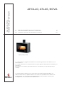 1
1
-
 2
2
-
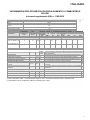 3
3
-
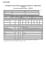 4
4
-
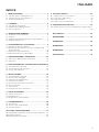 5
5
-
 6
6
-
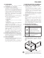 7
7
-
 8
8
-
 9
9
-
 10
10
-
 11
11
-
 12
12
-
 13
13
-
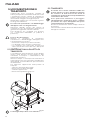 14
14
-
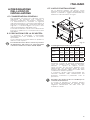 15
15
-
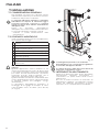 16
16
-
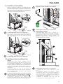 17
17
-
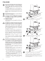 18
18
-
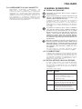 19
19
-
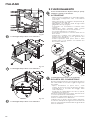 20
20
-
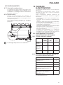 21
21
-
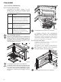 22
22
-
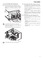 23
23
-
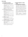 24
24
-
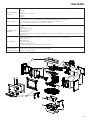 25
25
-
 26
26
-
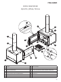 27
27
-
 28
28
-
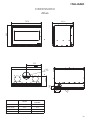 29
29
-
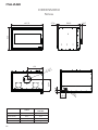 30
30
-
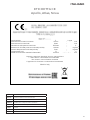 31
31
-
 32
32
-
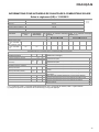 33
33
-
 34
34
-
 35
35
-
 36
36
-
 37
37
-
 38
38
-
 39
39
-
 40
40
-
 41
41
-
 42
42
-
 43
43
-
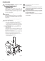 44
44
-
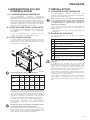 45
45
-
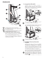 46
46
-
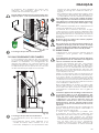 47
47
-
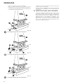 48
48
-
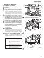 49
49
-
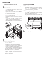 50
50
-
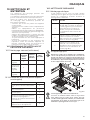 51
51
-
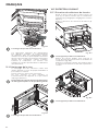 52
52
-
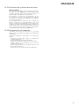 53
53
-
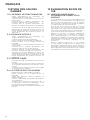 54
54
-
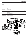 55
55
-
 56
56
-
 57
57
-
 58
58
-
 59
59
-
 60
60
-
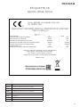 61
61
-
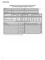 62
62
-
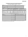 63
63
-
 64
64
-
 65
65
-
 66
66
-
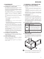 67
67
-
 68
68
-
 69
69
-
 70
70
-
 71
71
-
 72
72
-
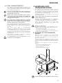 73
73
-
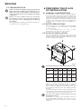 74
74
-
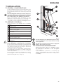 75
75
-
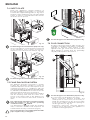 76
76
-
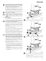 77
77
-
 78
78
-
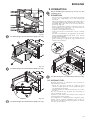 79
79
-
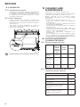 80
80
-
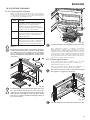 81
81
-
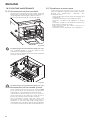 82
82
-
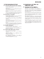 83
83
-
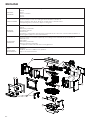 84
84
-
 85
85
-
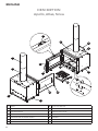 86
86
-
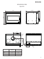 87
87
-
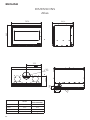 88
88
-
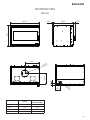 89
89
-
 90
90
-
 91
91
-
 92
92
-
 93
93
-
 94
94
-
 95
95
-
 96
96


Ravelli Nova Use and Maintenance Manual
- Categoría
- Estufas
- Tipo
- Use and Maintenance Manual
en otros idiomas
- français: Ravelli Nova
- italiano: Ravelli Nova
- English: Ravelli Nova
Artículos relacionados
Otros documentos
-
La Nordica Isetta Evo 4.0 El manual del propietario
-
La Nordica Concita El manual del propietario
-
-
La Nordica Jennifer El manual del propietario
-
La Nordica Nicoletta Forno Evo El manual del propietario
-
-
-
-
La Nordica Helga Evo El manual del propietario