Yamaha IMX644 Manual de usuario
- Categoría
- Controladores de DJ
- Tipo
- Manual de usuario

Owner's Manual
EN
LST0803-001B 008AP-02B0
© 2008 Yamaha Corporation
U.R.G., Pro Audio Division
Yamaha Pro Audio global web site:
http://www.yamahaproaudio.com/
Yamaha Manual Library
http://www.yamaha.co.jp/manual/

The above warning is located on the top of the unit.
Explanation of Graphical Symbols
The lightning flash with arrowhead symbol
within an equilateral triangle is intended to
alert the user to the presence of uninsulated
“dangerous voltage” within the product’s
enclosure that may be of sufficient magnitude
to constitute a risk of electric shock to
persons.
The exclamation point within an equilateral
triangle is intended to alert the user to the
presence of important operating and
maintenance (servicing) instructions in the
literature accompanying the product.
IMPORTANT SAFETY INSTRUCTIONS
1 Read these instructions.
2Keep these instructions.
3 Heed all warnings.
4 Follow all instructions.
5 Do not use this apparatus near water.
6 Clean only with dry cloth.
7 Do not block any ventilation openings. Install in
accordance with the manufacturer’s instructions.
8 Do not install near any heat sources such as
radiators, heat registers, stoves, or other apparatus
(including amplifiers) that produce heat.
9 Do not defeat the safety purpose of the polarized or
grounding-type plug. A polarized plug has two
blades with one wider than the other. A grounding
type plug has two blades and a third grounding
prong. The wide blade or the third prong are provided
for your safety. If the provided plug does not fit into
your outlet, consult an electrician for replacement of
the obsolete outlet.
10 Protect the power cord from being walked on or
pinched particularly at plugs, convenience
receptacles, and the point where they exit from the
apparatus.
11 Only use attachments/accessories specified by the
manufacturer.
12 Use only with the cart, stand,
tripod, bracket, or table
specified by the manufacturer,
or sold with the apparatus.
When a cart is used, use
caution when moving the cart/
apparatus combination to
avoid injury from tip-over.
13 Unplug this apparatus during lightning storms or
when unused for long periods of time.
14 Refer all servicing to qualified service personnel.
Servicing is required when the apparatus has been
damaged in any way, such as power-supply cord or
plug is damaged, liquid has been spilled or objects
have fallen into the apparatus, the apparatus has
been exposed to rain or moisture, does not operate
normally, or has been dropped.
(UL60065_03)
CAUTION: TO REDUCE THE RISK OF
ELECTRIC SHOCK, DO NOT REMOVE
COVER (OR BACK). NO USER-SERVICEABLE
PARTS INSIDE. REFER SERVICING TO
QUALIFIED SERVICE PERSONNEL.
CAUTION
RISK OF ELECTRIC SHOCK
DO NOT OPEN
WARNING
TO REDUCE THE RISK OF FIRE OR ELECTRIC SHOCK, DO NOT EXPOSE THIS APPARATUS TO RAIN OR MOISTURE.
1. IMPORTANT NOTICE: DO NOT MODIFY THIS UNIT!
This product, when installed as indicated in the instructions con-
tained in this manual, meets FCC requirements. Modifications not
expressly approved by Yamaha may void your authority, granted by
the FCC, to use the product.
2. IMPORTANT:
When connecting this product to accessories and/
or another product use only high quality shielded cables. Cable/s
supplied with this product MUST be used. Follow all installation
instructions. Failure to follow instructions could void your FCC
authorization to use this product in the USA.
3. NOTE:
This product has been tested and found to comply with the
requirements listed in FCC Regulations, Part 15 for Class “B” digital
devices. Compliance with these requirements provides a reason-
able level of assurance that your use of this product in a residential
environment will not result in harmful interference with other elec-
tronic devices. This equipment generates/uses radio frequencies
and, if not installed and used according to the instructions found in
the users manual, may cause interference harmful to the operation
of other electronic devices. Compliance with FCC regulations does
* This applies only to products distributed by YAMAHA CORPORATION OF AMERICA. (class B)
not guarantee that interference will not occur in all installations. If
this product is found to be the source of interference, which can be
determined by turning the unit “OFF” and “ON”, please try to elimi-
nate the problem by using one of the following measures:
Relocate either this product or the device that is being affected by
the interference.
Utilize power outlets that are on different branch (circuit breaker or
fuse) circuits or install AC line filter/s.
In the case of radio or TV interference, relocate/reorient the
antenna. If the antenna lead-in is 300 ohm ribbon lead, change the
lead-in to co-axial type cable.
If these corrective measures do not produce satisfactory results,
please contact the local retailer authorized to distribute this type of
product. If you can not locate the appropriate retailer, please con-
tact Yamaha Corporation of America, Electronic Service Division,
6600 Orangethorpe Ave, Buena Park, CA90620
The above statements apply ONLY to those products distributed by
Yamaha Corporation of America or its subsidiaries.
FCC INFORMATION (U.S.A.)

(5)-6
1/2
IMX644 Owner’s Manual
3
PRECAUTIONS
PLEASE READ CAREFULLY BEFORE PROCEEDING
* Please keep this manual in a safe place for future reference.
WARNING
Always follow the basic precautions listed below to avoid the possibility of serious injury or even death from electrical
shock, short-circuiting, damages, fire or other hazards. These precautions include, but are not limited to, the following:
• Only use the voltage specified as correct for the device. The required voltage is
printed on the name plate of the device.
• Use only the included power cord.
If you intend to use the device in an area other than in the one you purchased,
the included power cord may not be compatible. Please check with your Yamaha
dealer.
• Do not place the power cord near heat sources such as heaters or radiators, and
do not excessively bend or otherwise damage the cord, place heavy objects on
it, or place it in a position where anyone could walk on, trip over, or roll anything
over it.
• Be sure to connect to an appropriate outlet with a protective grounding
connection. Improper grounding can result in electrical shock.
• Do not open the device or attempt to disassemble the internal parts or modify
them in any way. The device contains no user-serviceable parts. If it should
appear to be malfunctioning, discontinue use immediately and have it inspected
by qualified Yamaha service personnel.
• Do not expose the device to dripping or splashing, use it near water or in damp
or wet conditions, or place containers on it containing liquids which might spill
into any openings. If any liquid such as water seeps into the device, turn off the
power immediately and unplug the power cord from the AC outlet. Then have
the device inspected by qualified Yamaha service personnel.
• Never insert or remove an electric plug with wet hands.
• If the power cord or plug becomes frayed or damaged, or if there is a sudden
loss of sound during use of the device, or if any unusual smells or smoke
should appear to be caused by it, immediately turn off the power switch,
disconnect the electric plug from the outlet, and have the device inspected by
qualified Yamaha service personnel.
• If this device should be dropped or damaged, immediately turn off the power
switch, disconnect the electric plug from the outlet, and have the device
inspected by qualified Yamaha service personnel.
CAUTION
Always follow the basic precautions listed below to avoid the possibility of physical injury to you or others, or damage
to the device or other property. These precautions include, but are not limited to, the following:
• Remove the electric plug from the outlet when the device is not to be used for
extended periods of time, or during electrical storms.
• When removing the electric plug from the device or an outlet, always hold the
plug itself and not the cord. Pulling by the cord can damage it.
• Before moving the device, remove all connected cables.
• When setting up the devices, make sure that the power switch can be easily
turned ON/OFF. If some trouble or malfunction occurs, immediately turn off the
power switch and disconnect the plug from the outlet.
• If the device is mounted in an EIA standard rack, carefully read the section
“Precautions for Rack Mounting” on page 7. Inadequate ventilation can result in
overheating, possibly causing damage to the device(s), malfunction, or even
fire.
•Avoid setting all equalizer controls and faders to their maximum. Depending on
the condition of the connected devices, doing so may cause feedback and may
damage the speakers.
• Do not expose the device to excessive dust or vibrations, or extreme cold or heat
(such as in direct sunlight, near a heater, or in a car during the day) to prevent
the possibility of panel disfiguration or damage to the internal components.
• Do not place the device in an unstable position where it might accidentally fall
over.
• Do not block the vents. This device has ventilation holes at the sides to prevent
the internal temperature from becoming too high. In particular, do not place the
device on its side or upside down. Inadequate ventilation can result in
overheating, possibly causing damage to the device(s), or even fire.
• Do not use the device in the vicinity of a TV, radio, stereo equipment, mobile
phone, or other electric devices. Doing so may result in noise, both in the device
itself and in the TV or radio next to it.
Power supply/Power cord
Do not open
Water warning
If you notice any abnormality
Power supply/Power cord
Location

(5)-6
2/2
4
IMX644 Owner’s Manual
• Before connecting the device to other devices, turn off the power for all devices.
Before turning the power on or off for all devices, set all volume levels to
minimum.
• The included power cable has a three-conductor plug, so if the AC outlet is
grounded the IMX644 will be grounded appropriately.
• When turning on the AC power in your audio system, always turn on the power
amplifier LAST, to avoid speaker damage. When turning the power off, the power
amplifier should be turned off FIRST for the same reason.
• Condensation can occur in the device due to rapid, drastic changes in ambient
temperature – when the device is moved from one location to another, or air
conditioning is turned on or off, for example. Using the device while
condensation is present can cause damage. If there is reason to believe that
condensation might have occurred, leave the device for several hours without
turning on the power until the condensation has completely dried out.
• Do not insert your fingers or hands in any gaps or openings on the device
(ports, etc.).
•Avoid inserting or dropping foreign objects (paper, plastic, metal, etc.) into any
gaps or openings on the device (ports, etc.) If this happens, turn off the power
immediately and unplug the power cord from the AC outlet. Then have the
device inspected by qualified Yamaha service personnel.
• Do not apply oil, grease, or contact cleaner to the faders. Doing so may cause
problems with electrical contact or fader motion.
• Do not rest your weight on the device or place heavy objects on it, and avoid use
excessive force on the buttons, switches or connectors.
Always turn the power off when the device is not in use.
The performance of components with moving contacts, such as switches, volume controls, and connectors, deteriorates over time. Consult qualified Yamaha service
personnel about replacing defective components.
SPECIAL NOTICES
• The illustrations as shown in this manual are for instructional purposes only, and may appear somewhat different from those on your device.
• The company names and product names in this manual are the trademarks or registered trademarks of their respective companies.
• Specifications and descriptions in this owner’s manual are for information purposes only. Yamaha Corp. reserves the right to change or modify products or specifications
at any time without prior notice. Since specifications, equipment or options may not be the same in every locale, please check with your Yamaha dealer.
Connections Handling caution
Yamaha cannot be held responsible for damage caused by improper use or modifications to the device, or data that is lost or destroyed.
European models
Purchaser/User Information specified in EN55103-1 and EN55103-2.
Inrush Current: 10 A
Conforms to Environments: E1, E2 E3 and E4
* This applies only to products distributed by
YAMAHA CORPORATION OF AMERICA.
COMPLIANCE INFORMATION STATEMENT
(DECLARATION OF CONFORMITY PROCEDURE)
Responsible Party : Yamaha Corporation of America
Address : 6600 Orangethorpe Ave., Buena Park, Calif. 90620
Telephone : 714-522-9011
Type of Equipment : DIGITAL INSTALLATION MIXER
Model Name : IMX644
This device complies with Part 15 of the FCC Rules.
Operation is subject to the following two conditions:
1) this device may not cause harmful interference, and
2) this device must accept any interference received including interfer-
ence that may cause undesired operation.
See user manual instructions if interference to radio reception is sus-
pected.
(FCC DoC)
IMPORTANT NOTICE FOR THE UNITED KINGDOM
Connecting the Plug and Cord
WARNING:
THIS APPARATUS MUST BE EARTHED
IMPORTANT. The wires in this mains lead are coloured in accor-
dance with the following code:
GREEN-AND-YELLOW : EARTH
BLUE : NEUTRAL
BROWN : LIVE
As the colours of the wires in the mains lead of this apparatus may
not correspond with the coloured markings identifying the terminals
in your plug proceed as follows:
The wire which is coloured GREEN-and-YELLOW must be con-
nected to the terminal in the plug which is marked by the letter E or
by the safety earth symbol or colored GREEN or GREEN-and-
YELLOW.
The wire which is coloured BLUE must be connected to the terminal
which is marked with the letter N or coloured BLACK.
The wire which is coloured BROWN must be connected to the termi-
nal which is marked with the letter L or coloured RED.
• This applies only to products distributed by Yamaha Music U.K. Ltd. (3 wires)

IMX644 Owner’s Manual
5
Table of contents
Introduction
Features ............................................................................... 6
Precautions for Rack Mounting ............................................ 7
Before Operation .................................................................. 7
Acquiring the IMX644 Manager Software and Manuals ....... 7
Controls and Functions
Front Panel ........................................................................... 8
Rear Panel.......................................................................... 10
Connections
System Example................................................................. 12
Connectors and Cables ...................................................... 13
Mix Functions
Input Channels ................................................................... 15
Output Channels................................................................. 17
Others................................................................................. 17
Appendix
Troubleshooting.................................................................. 18
Memory Initialization........................................................... 18
IMX644 Status List ............................................................. 19
Remote Control Protocol Specifications ............................. 20
General Specifications........................................................ 21
Input/output Characteristics................................................ 21
Electrical Characteristics .................................................... 22
GPI Circuit Example ........................................................... 23
Dimensions......................................................................... 24
Block Diagram .................................................................... 25

6
IMX644 Owner’s Manual
Introduction
Thank you for purchasing the Yamaha IMX644 Digital Installation Mixer. In order to take full
advantage of the IMX644 functionality and to ensure trouble-free operation, please read this
owner’s manual carefully before use. After you have read the manual, keep it in a safe place
for reference when needed.
■
Versatile Input/Output Configuration
The IMX644 features an input/output configuration that is ideal
for a wide range of applications: six mono inputs, four stereo in-
puts, two stereo outputs, two mono outputs, and one dedicated
stereo output for recording.
■
16 Memories
Up to 16 sets of mixer settings can be stored in memory and in-
stantly recalled as required. Four of the memories can be directly
recalled via front-panel MEMORY [A] through [D] buttons.
■
Optical Digital I/O
Connecting to compatible devices (CD and DVD players, for ex-
ample) via the optical digital interface allows accurate signal
transfer with no loss of signal quality. The digital input features
a built-in sample rate converter, so there is no need for word
clock synchronization.
■
Powerful Mixing Features
•Parametric EQ
Parametric equalization is provided on all input channels: 3-
band EQ on mono input channels, and 2-band EQ on stereo
input channels.
6-band EQ is provided on all outputs except the recording
output.
• Feedback Suppressor
Feedback suppression is provided on all six mono input
channels.
The Feedback Suppressor provides two stages of feedback
prevention: static filters that can be set in advance, and
dynamic filters that self-adjust in real time to control feed-
back.
• Priority for Specified Voice or Music Sources
The Priority Ducker automatically “ducks” (reduces the vol-
ume of) the background when a signal is applied to a speci-
fied mono input channel, making announcements stand out
for greater intelligibility. All stereo inputs assigned to the
same output channel are reduced to a specified level when
priority input is detected.
Music Override gives priority to a music source applied to a
specified stereo input channel. All other stereo inputs
assigned to the same output channel are muted when prior-
ity input is detected.
• Delay
Precise delays can be applied to all outputs to allow time
alignment for a solid sonic image with clear imaging and
optimum overall sound quality throughout the listening
area.
Features
Accessories
•AC power cord
• Rubber feet x 4
• Euroblock plug (3P) x 12
• Owner’s Manual (this document)

Introduction
IMX644 Owner’s Manual
7
This unit will operate stably in an environmental temperature of
0–40˚C. If you install this device together with multiple units of
the same device or other devices in an EIA standard rack, the
heat produced by the various devices may raise the ambient tem-
perature inside the rack, resulting in inefficient performance. To
ensure that the heat produced by this device can be dissipated ap-
propriately, please ensure the following conditions when rack-
mounting it.
• If multiple units are mounted in the same rack, leave a 1U
rack space between every two units. Also either leave the
open spaces uncovered or install appropriate ventilating
panels to minimize the possibility of heat buildup.
• When mounting this device together with other heat-pro-
ducing equipment such as power amplifiers, leave 1U or
more space between it and other devices. Install a ventila-
tion panel in this vacant space or leave it open to ensure ade-
quate cooling.
•To ensure sufficient airflow, leave the rear of the rack open
and position it at least 10 centimeters from walls or other
surfaces. If the rear of the rack can’t be left open, install a
commercially available fan or similar ventilating option to
secure sufficient airflow. If you’ve installed a fan kit, there
may be cases in which closing the rear of the rack will pro-
duce a greater cooling effect. Refer to the rack and/or fan
unit manual for details.
■
Connecting the AC Power Cable
CAUTION
• Before connecting the power cable, make sure that the power
switches of all devices are turned OFF.
First connect the supplied power cable to the [AC IN] socket on
the rear panel of the IMX644, then connect the AC plug to an ap-
propriate AC power outlet (make sure the local supply voltage
matches the rated AC voltage of the unit).
■
Powering ON or OFF
CAUTION
•To prevent loud noise bursts from the speakers when power-
ing up the system, turn devices ON in the following order:
audio sources (microphones, CD players, etc.), IMX644, and
finally power amplifiers. Reverse this order when turning the
system off.
1
Press the [ON] end of the [POWER] switch to
turn the unit ON.
2
Press the [OFF] end of the [POWER] switch to
turn the unit OFF.
CAUTION
• Rapidly turning the unit ON and OFF in succession can
cause it to malfunction. After turning the unit OFF, wait for
more than 6 seconds before turning it ON again.
The information in this manual deals primarily with setting up
and operating the IMX644 hardware.
For detailed parameter control the IMX644 Manager software
application is required. The IMX644 Manager software and
manuals can be downloaded from Yamaha’s professional audio
website (URL below).
http://www.yamahaproaudio.com/
The available IMX644 Manager documents are as follows:
• IMX644 Manager Owner’s Manual
This manual contains detailed information relating to the
IMX644 unit and IMX644 Manager software.
Precautions for Rack
Mounting
Before Operation
Acquiring the IMX644
Manager Software and
Manuals

8
IMX644 Owner’s Manual
Controls and Functions
1
[LOCK] Switch and Indicator
The [LOCK] switch can be used to “lock” the panel level knobs
(5, 8, and 11), making them inoperable and preventing acciden-
tal changes. After setting levels and/or recalling a memory as re-
quired, press the [LOCK] switch with a thin object (such as the
tip of a pen) to prevent further changes to the level settings. The
LOCK indicator lights red when the controls are locked.
Press the [LOCK] switch a second time to unlock the controls
and allow normal operation of the level knobs.
NOTE
• The LOCK buttons in the IMX644 Manager application
INPUT display can be used to enable independent operation
of each panel level control.
• If the settings of the level knobs have been increased since
the [LOCK] switch was engaged, the settings at the time the
[LOCK] switch was engaged will be retained when it is
disengaged. In order to increase a level setting after
disengaging the [LOCK] switch in such a case it is necessary
to lower the setting of the knob to the point at which it was
locked, and then raise the level as required.
• When the power is turned ON, the MEMORY number that
was active when the power was turned OFF is recalled. Save
the memory using the IMX644 Manager application before
engaging the [LOCK] switch.
• The LOCK function is temporarily disengaged when the
IMX644 Manager application goes online. The LOCK
function will be re-engaged if the unit is restarted, so don’t
operate the [LOCK] switch while the IMX644 Manager is
online.
2
[USB] Connector
The computer running the IMX644 Manager application can be
connected to the IMX644 via this connector. The [USB] connec-
tor cannot be used at the same time as the rear-panel [REMOTE]
connector.
Front Panel
13
578 !42 #
69)@
Precautions when using the [USB] connector
When connecting the computer to the [USB] connector,
make sure to observe the following points. Failing to do so
risks freezing the computer and corrupting or losing the data.
If the computer or the device freezes, restart the application
software or the computer OS, or turn the power to the device
off then on again.
CAUTION
• Use an AB type USB cable of less than about 3 meters.
• Before connecting the computer to the [USB] connector,
exit from any power-saving mode of the computer (such
as suspend, sleep, standby).
• Before turning on the power to the device, connect the
computer to the [USB] connector.
•Execute the following before turning the power to the
device on/off or plugging/unplugging the USB cable to/
from the [USB] connector.
- Quit any open application software on the computer.
- Make sure that data is not being transmitted from the
device.
• While the computer is connected to the device, you
should wait for six seconds or more between these
operations: (1) when turning the power of the device off
then on again, or (2) when alternately connecting/
disconnecting the USB cable.

Controls and Functions
IMX644 Owner’s Manual
9
■
MONO INPUT Section
3
Matrix Indicators
The outputs to which each mono input are assigned are displayed
by orange indicators.
4
[SIGNAL/PEAK] Indicators
These indicators light green when a signal is detected at the cor-
responding mono input.
The [SIGNAL/PEAK] indicators also light red to indicate exces-
sive input level at the corresponding input. If excessive input
level is indicated either reduce the output level of the connected
source, or reduce the IMX644 input sensitivity via the appropri-
ate rear-panel [PAD] switch or by reducing the [INPUT GAIN]
setting via the IMX644 Manager application.
5
Level Knobs
These knobs adjust the input level of the corresponding mono
channels.
■
STEREO INPUT Section
6
Matrix Indicators
The outputs to which each stereo input are assigned are dis-
played by orange indicators.
7
[SIGNAL/PEAK] Indicators
These indicators light green when a signal is detected at the cor-
responding stereo input.
The [SIGNAL/PEAK] indicators also light red to indicate exces-
sive input level at the corresponding input. If excessive input
level is indicated, reduce the output level of the connected
source.
NOTE
• The [SIGNAL/PEAK] indicator may light red when certain
types of signals are received via the OPTICAL input, but in
such cases the signal is within range and no further adjust-
ments are required.
8
Level Knobs
These knobs adjust the input level of the corresponding stereo
channels.
■
OUTPUT Section
9
Level Meter
Displays the levels of the signal being output via OUTPUT 1 and
2.
If the PEAK indicator lights the output level is too high. If exces-
sively high output levels are indicated, reduce the input and/or
output levels as required.
NOTE
• The signals OUTPUT 1 and 2 are both stereo pairs, so each
level meter indicates the output level of the mixed L and R
signal.
)
[SIGNAL/PEAK] Indicators
These indicators light green when a signal is detected at
OUTPUT 3 and 4.
The [SIGNAL/PEAK] indicators also light red to indicate exces-
sive output level at the corresponding output. If excessive output
level is indicated, reduce the input level or output level.
! Level Knobs
These knobs adjust the output level from the corresponding out-
put channels.
@ MEMORY [A] – [D] Buttons
• Recalling Memories
To recall a memory press and hold one of the MEMORY
buttons for about 2 seconds – the button’s indicator will
light and the mix settings assigned to that memory will be
recalled.
Settings are stored in the IMX644 memories via the
IMX644 Manager application. Memories A through D all
contain the same settings when the unit is initially shipped
from the factory.
• Switching Modes
To start the unit in IMX644 Manager mode, hold the MEM-
ORY [D] button while turning the [POWER] switch ON.
The unit starts up in the “normal” mode if the power is
turned on while the MEMORY [D] button is not held.
# [POWER] Switch & Indicator
Turns power to the unit ON or OFF. The indicator lights green
when the power is ON.
NOTE
• Since the level settings for each channel are stored in the
IMX644 unit itself, be sure that the IMX644 Manager applica-
tion is online when setting up the memories.
IMX644
Manager Mode
This mode allows communication with
the IMX644 application. Communica-
tion with AMX and similar external
controllers cannot occur in this mode.
Normal Mode
This is the unit’s normal operating
mode. Communication with AMX and
similar external controllers is also pos-
sible in this mode. Communication
with the IMX644 Manager application
is not possible in this mode.

Controls and Functions
10 IMX644 Owner’s Manual
NOTE
• Refer to “Connectors and Cables” on page 13 for details on connectors and cables for use with the IMX644.
1 [AC IN] Connector
Connect the supplied AC cable here.
First connect the AC cable to the IMX644, then plug it into an
appropriate AC outlet.
2 Earth Screw
For maximum safety, please earth the unit properly. The sup-
plied AC power cable is a 3-wire type, so if the AC outlet used
is properly earthed the IMX644 will be earthed as well. Hum and
interference may by further reduced in some cases by also con-
necting the earth screw to an earth point.
3 [REMOTE] Connector
This RS-232C connector allows communication with a comput-
er running the IMX644 Manager application or external control-
lers.
The [REMOTE] connector cannot be used simultaneously with
the front-panel [USB] connector. If both connectors are connect-
ed, the front-panel [USB] connector takes priority.
4 [GPI] Connector
This 25-pin D-sub GPI (General Purpose Interface) connector
provides eight input ports and eight output ports for a variety of
control signals, plus one dedicated output port that indicates the
unit’s power ON/OFF status.
■ STEREO INPUT Section
5 L/R Connectors 1, 2, 3, 4A, and OPTICAL 4B
The output from CD players and other stereo line-level sources
can be connected to these stereo inputs.
NOTE
• The 4A (L/R) connectors and 4B (OPTICAL) connector can-
not be used simultaneously.
■ REC OUT Section
6 L/R Connectors A and OPTICAL B
A CD recorder or other stereo recorder can be connected here.
NOTE
•A feedback loop can occur if a CD recorder or similar device
is connected to both a STEREO INPUT and the REC OUT
connectors. In such cases use the IMX644 Manager applica-
tion MATRIX controls to turn the OUTPUT channel to REC
OUT connector assignment off.
■ MONO INPUT Section
7 Euroblock Connectors
Microphones and similar mono sources can be connected to
these balanced input connectors. High-quality head amplifiers
are built in. Refer to page 13 for instructions on connecting to the
Euroblock connectors.
8 [PAD] Switches
When ON, input to the corresponding mono channel is attenuat-
ed by 34 dB. The pads are ideal for matching input sensitivity to
the output from wireless microphone tuners and similar high-
output source devices.
Rear Panel
1
246)
35 7 89

Controls and Functions
IMX644 Owner’s Manual 11
9 [+48V] Switch
When ON, 48V phantom power is applied to the corresponding
mono input. Turn the [+48V] switch ON for channels to which
phantom-powered condenser microphones or other devices that
require phantom power are connected.
CAUTION
• Make sure that phantom power is turned OFF unless it is
needed.
• When turning phantom power ON, make sure that no
equipment other than phantom-powered devices such
condenser microphones are connected to the corresponding
MONO INPUT connectors. Applying phantom power to a
device that does not require phantom power can damage the
device.
• Do not connect or disconnect a device to a MONO INPUT
while phantom power is applied. Doing so can damage the
connected device and/or the unit itself.
• Make sure that the system’s power amplifiers and/or powered
speakers are turned OFF while turning phantom power ON
or OFF to prevent damage to the speakers. We also
recommend setting all level controls to minimum level. If
these measures are not observed sudden high-level noise
bursts can potentially damage equipment and even the
hearing of people in the area.
■ OUTPUT Section
) Euroblock Connectors
These balanced output connectors are for connection to power
amplifiers and other output devices.
OUTPUT 1 and 2 are stereo outputs. The A connector outputs
the left-channel signal, and the B connector outputs the right-
channel signal. OUTPUT 1 and 2 can also be assigned for mono
output via the IMX644 Manager application.
OUTPUT 3 and 4 are mono outputs. Refer to page 13 for instruc-
tions on connecting to the Euroblock connectors.

12 IMX644 Owner’s Manual
Connections
System Example
1 2 3 4
5 6 7 8
Computer
CD recorder
Power amplifier
Power amplifier
External control input/
output device
AMX or similar external
controller
Microphone
Cassette deck
MD player
Wireless tuner
Wireless microphone
Zone 3 speakers
Zone 4 speakers
Zone 1
speakers
Zone 2
speakers

Connections
IMX644 Owner’s Manual 13
■ [MONO INPUT] and [OUTPUT] Con-
nectors (3-pin Euroblock)
Connect external microphones, amplifiers and other devices to
the rear-panel [MONO INPUT] and [OUTPUT] connectors via
cables fitted with the supplied 3-pin Euroblock plugs.
Follow the procedure outlined in this section to attach the Eurob-
lock plugs to the appropriate cables.
Use balanced lines to connect microphones and similar sources
to the [MONO INPUT] connectors. Wire balanced cables as
shown in the diagram below.
When an amplifier to be connected to the OUTPUT connector
has balanced XLR type inputs, wire the connection cable as
shown in the diagram below.
Euroblock Plug Connection
Use the included Euroblock plug (3P) to make connections to the
[MONO INPUT] and [OUTPUT] connectors.
1 Loosen the terminal screws.
NOTE
•A “minus” type screwdriver with a blade width of approxi-
mately 3 millimeters is recommended for Euroblock connec-
tor attachment.
2 Insert the cables.
Connectors and Cables
123
Euroblock Pin Assignments
Pin No.
Signal
name
1HOT
2 COLD
3 GND
1
1
2
3
2
3
XLR-3-11C (or equivalent)
1
2
2
3
1
3
XLR-3-12C (or equivalent)
● Cable preparation
•To prepare the cable for
attachment to a Eurob-
lock connector, strip the
wire as shown in the
illustration, and use
stranded wire to make
connections. With a Euroblock connection, the stranded
wire may be prone to breakage because of metal fatigue
due to the weight of the cable or due to vibration. When
rack-mounting your equipment, use a lacing bar when
possible to bundle and fasten the cables.
• If cables will be fre-
quently connected and
disconnected, as in the
case of a portable instal-
lation, we recommend
that you use ferrules with
insulation sleeves. Use a
ferrule whose conductor
portion has an external diameter of 1.6 mm or less, and a
length of approximately 7 mm (such as the AI0,5-6WH
made by the Phoenix Contact corporation).
CAUTION
• If you use stranded wire, do not tin (plate with solder) the
exposed end.
approx. 7 mm
approx. 7 mm
1.6 mm or less
3mm
Euroblock plug
Ter minal screw
Slotted screwdriver
Loosen

Connections
14 IMX644 Owner’s Manual
3 Securely tighten the terminal screws.
Pull the cables (not too strongly) to confirm that they are
securely connected.
4 Connect the Euroblock plug to the IMX644
Euroblock connector.
■ [REMOTE] Connector (RS-232C)
Connect to this connector when controlling the IMX644 from
the IMX644 Manager application or an external AMX/Crestron
controller. Use an RS-232C cross cable for connection.
An external AMX or similar controller can be used to send com-
mands to the IMX644 to recall memories and adjust the level of
individual channels. Refer to page 20 for information on the
available remote control commands.
■ [GPI] Connector (25-pin D-sub)
External GPI (General Purpose Interface) control devices can be
connected to this connector to allow input and output of remote
control signals.
The IMX644 GPI port has eight inputs and eight outputs, plus a
dedicated “POWER MONITOR” output that indicates the unit’s
ON/OFF status.
The input pins are normally left open. Shorting an input pin to
ground (GND) recalls the corresponding memory number.
The output pins are open-collector outputs that deliver a maxi-
mum output of +35 volts, with a maximum current capability of
30 mA per port.
For the POWER MONITOR outputs, pins 24 and 25 are
“closed” (shorted) when the power is ON. The POWER MONI-
TOR COLD pin (pin 25) is internally connected to the GND
pins.
The IMX644 Manager application can be used for parameter as-
signment.
1234
6789
5
Connector Pin
Assignments
Pin No. Signal name
1Unused
2 RxD
3 TxD
4 DTR
5 GND
6 DSR
7RTS
8 CTS
9Unused
Pin No. Signal name
1 GND
2 GND
3 INPUT 1
4 INPUT 2
5 INPUT 3
6 INPUT 4
7 INPUT 5
8 INPUT 6
9 INPUT 7
10 INPUT 8
11 GND
12 GND
13 GND
14 OUTPUT 1
15 OUTPUT 2
16 OUTPUT 3
17 OUTPUT 4
18 OUTPUT 5
19 OUTPUT 6
20 OUTPUT 7
21 OUTPUT 8
22 GND
23 GND
24 POWER MONITOR HOT
25 POWER MONITOR COLD
12345678910111213
25 24 23 22 21 20 19 18 17 16 15 14
Connector Pin Assignments

IMX644 Owner’s Manual 15
Mix Functions
The IMX644 mix functions can be programmed and edited in detail using the IMX644 Manager installed on a computer (page 7). The
mix functions that can be controlled by the IMX644 Manager application are discussed in this section. For operating details refer to the
IMX644 Manager Owner’s Manual.
To enable communication with the IMX644 Manager application, press and hold the IMX644 MEMORY [D] button while turning the
[POWER] switch ON.
■ GAIN
The gain of the mono input channel head amplifiers can be indi-
vidually adjusted and displayed.
■ INPUT EQ
The parameters of the input channel equalizers can be individu-
ally adjusted and displayed. The parameters available for each
channel are listed below.
MONO INPUT CHANNEL
STEREO INPUT CHANNEL
■ MATRIX
The MATRIX allows individual input channels to be assigned to
any of the mixer’s output channels. The assignments are shown
on the display. The initial default settings are: send assignments
to all output channels are ON, with only OUT1 assigned to the
REC OUT channel. The send levels from individual mono input
channels to the output channels can also be adjusted and dis-
played.
■ Temporary Matrix Assignment
Changes
The panel controls can be used to temporarily turn on the output
assignments of individual input channels, as follows.
1 Set all OUTPUT channel level controls to “0”.
2 Set the level of the INPUT channel to be
assigned to “10”.
3 Press and hold the MEMORY button correspond-
ing to the output channel you want to assign the
input channel to for longer than 3 seconds while
rotating the INPUT channel level control towards
“0”.
4 The corresponding MATRIX indicator will light.
5 Repeat for other channels as required.
NOTE
• Output assignments made in this way are only temporary and
will not be saved to memory. If power to the unit is turned
OFF and then ON again the memorized settings prior to
making the changes as described above will be recalled.
Input Channels
Parameter Range Initial value
GAIN (PAD is off) -54dB – -30dB -35dB
GAIN (PAD is ON) -20dB – +4dB -1dB
Parameter Range Initial value
HIGH
G -15dB – +15dB 0dB
F 2kHz – 18kHz 10kHz
MID
G -15dB – +15dB 0dB
F 40Hz – 18kHz 2kHz
Q 0.5 – 12.0 0.7
LOW
G -15dB – +15dB 0dB
F 40Hz – 2kHz 100Hz
Parameter Range Initial value
HIGH
G -15dB – +15dB 0dB
F 2kHz – 18kHz 10kHz
LOW
G -15dB – +15dB 0dB
F 40Hz – 2kHz 100Hz
Parameter Range Initial value
SEND LEVEL -∞ – 0dB 0dB
Button Output channel
A OUTPUT 1
B OUTPUT 2
C OUTPUT 3
D OUTPUT 4

Mix Functions
16 IMX644 Owner’s Manual
■ Feedback Suppressor
The Feedback Suppressor effectively controls feedback by iden-
tifying the feedback frequencies that will occur naturally as a re-
sult of the combined acoustic and electrical characteristics of the
sound system within the acoustic space in which it is used. The
Feedback Suppressor includes static filters that provide mea-
surement and filtering for specified channels, and dynamic fil-
ters that monitor the condition of specified MONO INPUT
channels and automatically suppress feedback as it occurs.
Static filter measurements can be made either via the IMX644
Manager application or the IMX644 unit itself. Measurement
from the IMX644 itself is described in “Front Panel Static Filter
Measurement” below.
With the initial default settings the static filters are inactive,
while the dynamic filters are ON for all MONO INPUT chan-
nels.
NOTE
• The initial default setting is Feedback Suppressor ON. Even
though the static filters are inactive, the dynamic filters are
still operational so be sure to turn the Feedback Suppressor
OFF before using sine waves or test tones to test or calibrate
the system.
•Feedback Suppressor settings can be stored in the unit’s 16
memories.
Front Panel Static Filter Measurement
To ensure optimum feedback suppression be sure to perform the
measurements under the same conditions that will prevail during
actual operation (microphone and speaker positions, etc.).
1 Set the OUTPUT channel 1 through 4 level con-
trols to 3 o’clock.
2 Set the level control of the MONO INPUT to
which the microphone that is to be used for
measurement is connected to 3 o’clock.
3 Set up the microphone at least 5 meters away
from the speakers.
4 Adjust the output level of the power amplifier.
While speaking or singing into the microphone gradually
raise the output level of the power amplifier to the level
that will be used in actual operation. Also clap your hands
near the microphone to make sure that feedback does not
occur.
5 Set the level control of the MONO INPUT channel
to which the microphone that is to be used for
measurement is connected to “0”.
6 Make sure the area being measured is silent.
7 Simultaneously press and hold MEMORY but-
tons [A], [C], and [D] for longer than two sec-
onds. The MEMORY [A], [C], and [D] button
indicators will light and static filter measure-
ment will begin. When the measurement process
has finished the static filter will be set according
to the results and the MEMORY button indica-
tors will return to their status prior to the mea-
surement.
NOTE
• If all four MEMORY button indicators light – [A], [B], [C], and
[D] – an error has occurred during measurement. To prevent
damage to the equipment the measurement will be aborted
and the erroneous data discarded. If this occurs try changing
the orientation of the microphone and speakers, lower the
amplifier output, then repeat the procedure from step 1
above.
• Static filter measurement may not be successful if the overall
level is too high or the microphone is too close to one of the
speakers.
■ Priority Ducker
When a signal is applied to the specified MONO INPUT channel
the level of all STEREO INPUT signals assigned to the same
output are reduced to allow announcements made via the MONO
INPUT channel to stand out clearly from background music or
other program material, for example. When input to the specified
MONO INPUT channel ceases the level of the other “ducked”
channels returns to normal.
The initial default setting is OFF for all channels.
Both the amount of attenuation and the time it takes to return to
normal level can be programmed as required.
■ Music Override
When a signal is applied to the specified STEREO INPUT chan-
nel all other STEREO INPUT channels assigned to the same out-
put are automatically faded out and muted. When input to the
specified STEREO INPUT channel ceases the level of the other
muted channels fades in and returns to normal.
The initial default setting is OFF for all channels.
The time it takes to fade-in to normal level can be programmed
as required.
NOTE
• If Music Override is ON for more than one channel, the low-
est-numbered channel takes priority.
Parameter Range Initial value
Mute Level -30.2dB – 0dB -20dB
Release Time 0.0 – 6.0sec 2.0sec
Parameter Range Initial value
Release Time 0.0 – 6.0sec 4.0sec

Mix Functions
IMX644 Owner’s Manual 17
■ OUTPUT EQ
The parameters of the independent 6-band parametric equalizers
provided for OUTPUT channels 1 through 4 can be adjusted and
displayed. The following EQ types can be specified for each
band.
The initial default settings when the P.EQ type is selected are as
follows.
■ DELAY
Sets the output channel delay time.
One of the main uses for this feature is to delay the output to sub
speakers slightly compared to the main speakers, to create a solid
frontal sonic image.
■ BALANCE
Adjusts the A/B level balance for OUTPUT channels 1 and 2.
■ Output Format (STEREO/MONO)
Specifies whether OUTPUT channels 1 and 2 deliver a STEREO
or MONO output signal. When [STEREO] is selected the left
channel signal is delivered via the A connector and the right-
channel signal is delivered via the B connector. The initial de-
fault setting is [STEREO].
■ GPI (General Purpose Interface)
• GPI Input
Applying an appropriate input to one of the rear-panel GPI
input ports recalls the assigned memory. Individual assign-
ments can be made for each input port.
• GPI Output
Recalling a memory causes a pre-assigned combination of
ON and OFF outputs to appear at the GPI output ports. The
ON/OFF combinations can be independently assigned for
each memory.
The initial default assignments for all memories are all out-
puts OFF.
■ MEMORY
Up to 16 sets of parameters can be memorized. Of those, four
can be assigned for direct recall from the front-panel MEMORY
[A] through [D] buttons. For access to five or more memories at
a time either use the IMX644 Manager application, or a suitable
external controller connected to the GPI interface.
NOTE
• MEMORY buttons [A] through [D] are initially set up to recall
the same data.
• Since the level settings for each channel are stored in the
IMX644 unit itself, be sure that the IMX644 Manager
application is online when setting up the memories.
Output Channels
Type Parameter Range
PEQ (Peaking EQ)
F 40Hz – 18kHz
G -15dB – +15dB
Q 0.5 – 12.0
HPF (High Pass Filter)
F 40Hz – 18kHz
Slope 12dB/oct (Fixed)
Q 0.7 (Fixed)
LPF (Low Pass Filter)
F 40Hz – 18kHz
Slope 12dB/oct (Fixed)
Q 0.7 (Fixed)
L. Shelf (Low Shelving EQ)
F 40Hz – 18kHz
G -15dB – +15dB
H.Shelf (High Shelving EQ)
F 40Hz – 18kHz
G -15dB – +15dB
Parameter Initial value
Q 0.7 (for all frequency parameters)
F1 40Hz
F2 100Hz
F3 500Hz
F4 2kHz
F5 5kHz
F6 10kHz
Parameter Range Initial value
DELAY 0 – 300msec 0msec
Parameter Range Initial value
BALANCE 0dB – 20.1dB 0dB
Others

18 IMX644 Owner’s Manual
Appendix
The following procedure initializes the IMX644 memory.
CAUTION
• All data stored in memory will be erased when the memory is initialized. Perform the following procedure with caution.
1 Turn the IMX644 power OFF.
2 Turn the power back ON while simultaneously holding the MEM-
ORY [A] and [D] buttons.
Initialization will take about one second.
When initialization is complete the odd-numbered matrix input channel indica-
tors will light.
Troubleshooting
Symptom Possible Cause Solution
The power won’t turn on.
The power cable is not prop-
erly connected.
After connecting the power cable to the connector on the rear panel
of the IMX644, plug the cable into an appropriate AC outlet.
No sound.
The audio cables are not
properly connected.
Check all audio connections.
Connected devices are not
turned ON.
Check to make sure that the power to all connected devices is turned ON.
Wrong matrix settings.
Check the matrix indicators to make sure that the input and output
assignments are correct. If the matrix settings are not appropriate
use the IMX644 Manager application to set them as required. Also
check the matrix send levels.
Level settings too low.
Make sure that the panel level controls are set appropriately. If this
doesn’t produce the desired output check the settings via the IMX644
manager application.
Sound levels don’t change
when the level knobs are
operated.
The LOCK function may be
engaged.
Disengage the main LOCK function via the IMX644 panel (page 8),
or disengage LOCK for a specific knob via the IMX644 Manager
application.
Pressing a MEMORY button
results in no change to the
settings.
The MEMORY button is not
being held long enough.
Press and hold the MEMORY button for longer than two seconds.
No settings have been
saved in memory.
Make the required settings via the IMX644 Manager application, and
then save them to the appropriate memory.
The appropriate memory-to-
button assignment has not
been made.
Use the IMX644 Manager application to assign the desired memory
to the button.
The IMX644 cannot be locked.
The [LOCK] switch hasn’t
been properly pressed. The
LOCK indicator will be off if
the controls aren’t locked.
Press the [LOCK] switch (page 8). The LOCK indicator will light when
the controls are locked.
The [LOCK] switch doesn
’
t
work.
The IMX644 has been
locked via the IMX644 Man-
ager application.
Make sure that the [LOCK] buttons in the IMX644 Manager BLOCK
or INPUT screen are turned on (pages 21 and 24 of the IMX644
Manager owner’s manual).
Memory cannot be recalled
via the GPI interface.
A memory is not assigned to
the GPI input.
Use the IMX644 Manager application to assign the desired memory
to the GPI Input Terminal.
The IMX644 cannot be oper-
ated from an external con-
troller (AMX/Crestron).
The IMX644 is operating in
IMX644 Manager mode.
Turn the IMX644 power OFF, and then after waiting for at least six
seconds turn the power ON again (without
holding the MEMORY [D]
button) to start the IMX644 in “normal” mode.
The IMX644 cannot be oper-
ated from the IMX644 Man-
ager application.
The IMX644 is operating in
normal mode.
Turn the IMX644 power OFF, and then after waiting for at least six
seconds turn the power ON again while holding the MEMORY [D]
button to start the IMX644 in “IMX644 Manager” mode.
The Parameter Edit screen
will not open when the pass-
word is entered via the
IMX644 Manager.
The password is incorrect.
Initialize the internal IMX644 memory if the password has been lost
or forgotten.
Memory Initialization

Appendix
IMX644 Owner’s Manual 19
3 To recall the initial memory data press a MEMORY button for longer than two seconds.
NOTE
• Initialization erases the password required to connect the IMX644 Manager application to the IMX644 unit. After initialization it will be
necessary to set a new password to bring the IMX644 online.
The chart below shows the panel and memory recall operations that are effective with various combinations of modes, panel LOCK
settings, and IMX644 Manager LOCK/LINK settings, and whether the panel or memorized level settings are applied when a memory
is recalled.
* When the IMX644 is online in the IMX644 Manager mode, LOCK is temporarily disengaged and the panel [LOCK] indicator will go
out. Do not operate the panel [LOCK] switch in this condition.
NOTE
• Since the level settings for each channel are stored in the IMX644 unit itself, be sure that the IMX644 Manager application is online
when setting up the memories.
IMX644 Status List
IMX644 Settings
Individual
Channel Settings
(IMX644
Manager)
Operations that Affect Actual
Level
Operations that Recall Memories
[LOCK]
indicator
[LOCK]
button
[LINK]
button
Level
Knobs
IMX644
Manager
Control
External
Controller
MEMORY
buttons
GPI
IMX644
Manager
Control
External
Controller
Level
Setting
IMX644
Manager
Mode
Offline
unlit ON ON Effective – –
Effective Effective – –
Level Knob
Setting
unlit ON OFF Effective – –
Memory
Setting
unlit OFF ON Effective – –
Level Knob
Setting
unlit OFF OFF Effective – –
Memory
Setting
lit ON ON Invalid – –
Effective Effective – –
Memory
Setting
lit ON OFF Invalid – –
Memory
Setting
lit OFF ON Effective – –
Level Knob
Setting
lit OFF OFF Effective – –
Memory
Setting
Online*
unlit ON ON Effective Invalid –
Effective Effective Effective –
Level Knob
Setting
unlit ON OFF Invalid Effective –
Memory
Setting
unlit OFF ON Effective Invalid –
Level Knob
Setting
unlit OFF OFF Invalid Effective –
Memory
Setting
Normal Mode
unlit ON ON Effective – Effective
Effective Effective – Effective
Level Knob
Setting
unlit ON OFF Effective – Effective
Memory
Setting
unlit OFF ON Effective – Effective
Level Knob
Setting
unlit OFF OFF Effective – Effective
Memory
Setting
lit ON ON Invalid – Effective
Effective Effective – Effective
Memory
Setting
lit ON OFF Invalid – Effective
Memory
Setting
lit OFF ON Effective – Effective
Level Knob
Setting
lit OFF OFF Effective – Effective
Memory
Setting

Appendix
20 IMX644 Owner’s Manual
The commands that can be transferred between the IMX644 and a remote controller are as follows.
<Command> <Option 1> <Option 2> … <Option n> <Line Feed>
•A line feed (LF = 0x0A) is necessary at then end of every command line.
• At least one character space is required between the command name and first option, and between options.
■ Communication Specifications
Baud Rate : 38400 bps
Data : 8bit
Parity : none
Stop Bit : 1bit
Flow Control : none
Memory Recall Individual Channel Level Control
m: memory number (1–16)
Remote Control Protocol Specifications
Communication Direction Command
External Controller IMX644
RSC 0 m
External Controller IMX644
RSC OK
External Controller IMX644
SCN 0 m
External Controller IMX644
External Controller IMX644
External Controller IMX644
VOL 0 0 x
VOL 0 1 x
VOL 0 13 x
➜
➜
➜
➜
➜
...
➜
...
Communication Direction Command
External Controller IMX644
SVL 0 c x
External Controller IMX644
SVL OK
External Controller IMX644
VOL 0 c x
➜
➜
➜
c: channel number (0–13)
0 MONO 1
1 MONO 2
2 MONO 3
3 MONO 4
4 MONO 5
5 MONO 6
6 STEREO 1
7 STEREO 2
8 STEREO 3
9 STEREO 4
10 OUTPUT1
11 OUTPUT2
12 OUTPUT3
13 OUTPUT4
x: level value (0–127)
127 -∞
126 -∞
125 -∞
124 -111.4
123 -102.4
122 -94.4
121 -88.4
120 -83.4
119 -78.4
118 -74.4
117 -70.4
116 -66.4
115 -63.8
114 -60.6
113 -57.6
112 -55.1
111 -52.9
110 -50.9
109 -49.1
108 -47.5
107 -46.0
106 -44.5
105 -43.1
104 -41.7
103 -40.4
102 -39.1
101 -37.9
100 -36.7
99 -35.6
98 -34.5
97 -33.6
96 -32.7
95 -31.8
94 -31.0
93 -30.2
92 -29.4
91 -28.7
90 -28.0
89 -27.3
88 -26.7
87 -26.1
86 -25.5
85 -24.9
84 -24.4
83 -23.9
82 -23.4
81 -22.9
80 -22.4
79 -22.0
78 -21.6
77 -21.2
76 -20.8
75 -20.4
74 -20.0
73 -19.6
72 -19.2
71 -18.8
70 -18.4
69 -18.0
68 -17.6
67 -17.2
66 -16.8
65 -16.4
64 -16.0
63 -15.6
62 -15.2
61 -14.8
60 -14.4
59 -14.0
58 -13.6
57 -13.2
56 -12.8
55 -12.4
54 -12.0
53 -11.6
52 -11.2
51 -10.8
50 -10.4
49 -10.0
48 -9.6
47 -9.2
46 -8.8
45 -8.4
44 -8.0
43 -7.6
42 -7.2
41 -6.8
40 -6.4
39 -6.0
38 -5.6
37 -5.2
36 -4.8
35 -4.4
34 -4.0
33 -3.6
32 -3.2
31 -2.8
30 -2.4
29 -2.0
28 -1.6
27 -1.2
26 -0.8
25 -0.4
24 0.0
23 0.4
22 0.8
21 1.2
20 1.6
19 2.0
18 2.4
17 2.8
16 3.2
15 3.7
14 4.2
13 4.7
12 5.2
11 5.8
10 6.5
9 7.3
8 8.1
7 9.0
6 10.0
5 10.0
4 10.0
3 10.0
2 10.0
1 10.0
0 10.0

Appendix
IMX644 Owner’s Manual
21
ANALOG INPUT CHARACTERISTICS
* 0dBu = 0.775 Vrms. , 0dBV = 1.00 Vrms.
* +48V DC( phantom power ) is supplied to MONO INPUT[1-6] EUROBLOCK connectors via each individual switch.
* All AD converters are 24 bit linear, 64times oversampling.
ANALOG OUTPUT CHARACTERISTICS
* 0dBu = 0.775 Vrms. , 0dBV = 1.00 Vrms.
* All DA converters are 24 bit linear,128times oversampling.
CONTROL I/O CHARACTERISTICS
*1 INPUT: 8 ports, OUTPUT: 8 ports
OUTPUT: Withstanding Voltage Vmax = 35V (OFF)
OUTPUT: Sink Current Imax = 30mA/1 port, Imax = 240mA/8 ports (ON)
OUTPUT: Shorted to GND when ON
POWER MONITOR: OPEN (POWER OFF), SHORT (POWER ON)
POWER MONITOR: Withstanding Voltage Vmax = 35V (POWER OFF)
POWER MONITOR: Sink Current Imax = 30mA (POWER ON)
General Specifications
Signal Delay 2.5ms (MONO INPUT [1-6] to OUTPUT[1-4])
Dimensions (W x H x D) 480 x 88 x 364.5 mm
Net Weight 5.5kg
Power Requirements
U.S/Canada: 120V, 60Hz
Korea: 220V, 60Hz
China: 220V, 50Hz
Other: 110V-240V, 50/60Hz
Power Consumption 21W
Heat Dissipation 18.06 kcal/h
Temperature range
Operating: 0 to +40˚C
Storage: -20 to +60˚C
Included Accessories Owner’s Manual, AC Power Cord, Rubber feet x 4, 3-pin Euroblock plug x 12
AC Power Cord Length 200 cm
Conditions Min. Typ. Max. Unit
Sampling Frequency External Clock Frequency Range – 39.69 – 50.88 kHz
Sampling Frequency Internal Clock Frequency word clock : int 48kHz – 48 – kHz
Input/output Characteristics
Input Terminals
PAD
34dB
GAIN
Actual Load
Impedance
For Use With
Nominal
Input level
Connector
Nominal Max. before clip
MONO INPUT [1-6]
OFF
MAX
4.2kΩ
50-600Ω Mics
& 600Ω Lines
-54dBu (1.55mV) -40dBu (7.75mV)
EUROBLOCK
(Balanced)
(5.08mm pitch)
MIN -30dBu (24.5mV) -16dBu (123mV)
ON
MAX
20kΩ
-20dBu (77.5mV) -6dBu (387mV)
MIN +4dBu (1.23V) +18dBu (6.16V)
STEREO INPUT [1L/R,
2L/R, 3L/R, 4A L/R]
– 20kΩ 600Ω Lines -4dBV (0.631V) +10dBV (3.16V)
RCA Pin Jack
(Unbalanced)
Output Terminals
Actual Source
Impedance
For Use With
Nominal
Output level
Connector
Nominal Max. before clip
OUTPUT [1A/B, 2A/B, 3, 4] 900Ω 10kΩ Lines +4dBu (1.23V) +18dBu (6.16V)
EUROBLOCK
(Balanced)
(5.08mm pitch)
REC OUT [L, R] 450Ω 10kΩ Lines -4dBV (0.631V) +10dBV (3.16V)
RCA Pin Jack
(Unbalanced)
Terminal Format Level Connector
GPI *1
IN Mechanical “make” contact Compatible with open collector output
D-SUB 25P (Female)OUT – Open Collector
POWER MONITOR OUTPUT – Open Collector
REMOTE RS-232C RS-232C D-SUB 9P (Male)
USB USB 1.1 Function – Type B
DIGITAL INPUT CHARACTERISTICS
*1 0dBm = 1mW
DIGITAL OUTPUT CHARACTERISTICS
*1 0dBm = 1mW
Terminal Format
Data
length
Level Connector
STEREO
INPUT [4B]
JEITA
CP-1212
24bit -24 to –14.5dBm *1
OPTICAL
Square
Terminal Format
Data
length
Level Connector
REC OUT
JEITA
CP-1212
24bit -21 to –15dBm *1
OPTICAL
Square

Appendix
22 IMX644 Owner’s Manual
Output impedance of signal generator : 150 ohms
Frequency Response
20Hz-20kHz, reference to the nominal output level @1kHz
Total Harmonic Distortion
@1kHz
*Total Harmonic Distortion are measured with a 22kHz low pass filter
EIN (EIN=Equivalent Input Noise)
* EIN are measured with a IHF-A filter
Hum & Noise
* Hum & Noise are measured with a DIN AUDIO filter
Crosstalk
@1kHz
Maximum voltage gain
@1kHz
Phantom Voltage
Indicator turn on level
Level Meter turn on level
Electrical Characteristics
Input Output RL Conditions Min. Typ. Max. Unit
MONO INPUT [1-6] OUTPUT [1-4] 10KΩ – -1.5 0.0 0.5 dB
STEREO INPUT [1L/R-4L/R] OUTPUT [1-4] 10KΩ –-10.0 0.5 dB
STEREO INPUT [1L/R-4L/R] REC OUT [L, R] 10KΩ –-10.0 0.5 dB
OPTICAL IN OUTPUT [1-4] 10KΩ –-10.0 0.5 dB
OPTICAL IN REC OUT [L, R] 10KΩ –-10.0 0.5 dB
Input Output RL Conditions Min. Typ. Max. Unit
MONO INPUT [1-6] OUTPUT [1-4] 10KΩ +4dBu@1kHz, GAIN: MAX, PAD: OFF – – 0.1 %
MONO INPUT [1-6] OUTPUT [1-4] 10KΩ +4dBu@1kHz, GAIN: MIN, PAD: ON – – 0.08 %
STEREO INPUT [1L/R-4L/R] OUTPUT [1-4] 10KΩ +4dBu@1kHz – – 0.1 %
STEREO INPUT [1L/R-4L/R] REC OUT [L, R] 10KΩ -4dBV@1kHz – – 0.1 %
Input Output RL Conditions Min. Typ. Max. Unit
MONO INPUT [1-6] OUTPUT [1-4] 10KΩ
Rs=150Ω, GAIN:MAX, PAD: OFF
OUTPUT level control at nominal level and one
INPUT level control at nominal level.
––-120 dBu
Input Output RL Conditions Min. Typ. Max. Unit
– OUTPUT [1-4] 10KΩ all level control at minimum level – – -82 dBu
– REC OUT [L, R] 10KΩ all level control at minimum level – – -90 dBV
from/to to/from Conditions Min. Typ. Max. Unit
CH N CH (N-1) or (N+1) all adjacent inputs – – -70 dB
CH N CH (N-1) or (N+1) all adjacent outputs – – -70 dB
Input Output RL Conditions Min. Typ. Max. Unit
MONO INPUT [1-6] OUTPUT [1-4] 10KΩ Rs=150Ω, GAIN: MAX, PAD: OFF – 58 – dB
MONO INPUT [1-6] REC OUT [L, R] 10KΩ Rs=150Ω, GAIN: MAX, PAD: OFF – 52.2 – dB
Output Conditions Min. Typ. Max. Unit
MONO INPUT [1-6] hot & cold: No load 46 48 50 V
Input Output Conditions Min. Typ. Max. Unit
MONO INPUT [1-6]
STEREO INPUT [1L/R-4L/R]
–
PEAK red LED: ON -4 -2 0 dBFs
SIGNAL green LED: ON -42 -38 -34 dBFs
– OUTPUT [3, 4]
PEAK red LED: ON -4 -2 0 dBFs
SIGNAL green LED: ON -48 -44 -40 dBFs
Input Output Conditions Min. Typ. Max. Unit
– OUTPUT [1,2]
PEAK red LED: ON -4 -2 0 dBFs
-8 orange LED: ON -10 -8 -6 dBFs
-14 orange LED: ON -16 -14 -12 dBFs
-20 green LED: ON -22 -20 -18 dBFs
-32 green LED: ON -34 -32 -30 dBFs
-44 green LED: ON -48 -44 -40 dBFs

Appendix
IMX644 Owner’s Manual
23
■ Example: Controlling the IMX644 from a switch
■ Example: Lighting the LED of an external device from the IMX644
■ Example: Lighting the LED of an external device while the IMX644 power is ON.
GPI Circuit Example
IMX644
+5V
CPU
1K
47K
22K
INPUT
GND
IMX644
110
CPU
GND
OUTPUT
Max.30mA
Max. +35V
Lit
IMX644
110
Power ON
Max.30mA
Max. +35V
Lit
POWER
MONITOR
HOT
POWER
MONITOR
COLD

Appendix
24 IMX644 Owner’s Manual
* Specifications and descriptions in this owner’s manual are for information purposes only. Yamaha Corp. reserves the right to change
or modify products or specifications at any time without prior notice. Since specifications, equipment or options may not be the same
in every locale, please check with your Yamaha dealer.
Dimensions
480
88
364.5
340
618.5
Unit: mm

Appendix
IMX644 Owner’s Manual
25
Block Diagram
+48V
MONO 1 - 6
ON
+48V
AD
+
-
INPUT GAIN
SIGNAL
PEAK
1
2
3
3BAND
PEQ
LEVEL
F. B .
SUP
TO OUT1
TO OUT2
OUT 1A(L) BUS
OUT 1B(R) BUS
OUT 2A(L) BUS
OUT 2B(R) BUS
OUT 3 BUS
OUT 4 BUS
TO OUT3
TO OUT4
PAD
34dB
STEREO 1-3
AD
SIGNAL
PEAK
2BAND
PEQ
LEVEL
TO OUT1
TO OUT2
TO OUT3
TO OUT4
AD
2BAND
PEQ
Priority
Ducker
Music
Override
L
R
STEREO 4A
SIGNAL
PEAK
2BAND
PEQ
LEVEL
TO OUT1
TO OUT2
TO OUT3
TO OUT4
2BAND
PEQ
Priority
Ducker
Music
Override
DIR SRC
AD
AD
OPTICAL
SIGNAL
PEAK
LEVEL
DELAY
6BAND
PEQ
6BAND
PEQ
DELAY
BALANCE
1
2
3
DA
+
-
1
2
3
DA
+
-
OUT1 A(L)
OUT1 B(R)
LEVEL
DELAY
6BAND
PEQ
6BAND
PEQ
DELAY
BALANCE
1
2
3
DA
+
-
1
2
3
DA
+
-
OUT2 A(L)
OUT2 B(R)
LEVEL
DELAY
6BAND
PEQ
6BAND
PEQ
DELAY
1
2
3
DA
+
-
1
2
3
DA
+
-
OUT3
OUT4
SIGNAL
PEAK
LEVEL
DA
DA
DIT
REC OUT
A
STEREO 4B
REC OUT B
MONO/
STEREO
MONO/
STEREO
L
R
OPTICAL
L
R

Information for Users on Collection and Disposal of Old Equipment
This symbol on the products, packaging, and/or accompanying documents means that used
electrical and electronic products should not be mixed with general household waste.
For proper treatment, recovery and recycling of old products, please take them to applicable col-
lection points, in accordance with your national legislation and the Directives 2002/96/EC.
By disposing of these products correctly, you will help to save valuable resources and prevent
any potential negative effects on human health and the environment which could otherwise arise
from inappropriate waste handling.
For more information about collection and recycling of old products, please contact your local
municipality, your waste disposal service or the point of sale where you purchased the items.
[For business users in the European Union]
If you wish to discard electrical and electronic equipment, please contact your dealer or supplier
for further information.
[Information on Disposal in other Countries outside the European Union]
This symbol is only valid in the European Union. If you wish to discard these items, please con-
tact your local authorities or dealer and ask for the correct method of disposal.

For details of products, please contact your nearest Yamaha representative or the authorized distributor listed below.
CANADA
Yamaha Canada Music Ltd.
135 Milner Avenue, Scarborough, Ontario,
M1S 3R1, Canada
Tel: 416-298-1311
U.S.A.
Yamaha Corporation of America
6600 Orangethorpe Ave., Buena Park, Calif. 90620,
U.S.A.
Tel: 714-522-9011
MEXICO
Yamaha de México S.A. de C.V.
Calz. Javier Rojo Gómez #1149,
Col. Guadalupe del Moral
C.P. 09300, México, D.F., México
Tel: 55-5804-0600
BRAZIL
Yamaha Musical do Brasil Ltda.
Rua Joaquim Floriano, 913 - 4' andar, Itaim Bibi,
CEP 04534-013 Sao Paulo, SP. BRAZIL
Tel: 011-3704-1377
ARGENTINA
Yamaha Music Latin America, S.A.
Sucursal de Argentina
Olga Cossettini 1553, Piso 4 Norte
Madero Este-C1107CEK
Buenos Aires, Argentina
Tel: 011-4119-7000
PANAMA AND OTHER LATIN
AMERICAN COUNTRIES/
CARIBBEAN COUNTRIES
Yamaha Music Latin America, S.A.
Torre Banco General, Piso 7, Urbanización Marbella,
Calle 47 y Aquilino de la Guardia,
Ciudad de Panamá, Panamá
Tel: +507-269-5311
THE UNITED KINGDOM
Yamaha Music U.K. Ltd.
Sherbourne Drive, Tilbrook, Milton Keynes,
MK7 8BL, England
Tel: 01908-366700
GERMANY
Yamaha Music Europe GmbH
Siemensstraße 22-34, 25462 Rellingen, Germany
Tel: 04101-3030
SWITZERLAND/LIECHTENSTEIN
Yamaha Music Europe GmbH
Branch Switzerland in Zürich
Seefeldstrasse 94, 8008 Zürich, Switzerland
Tel: 01-383 3990
AUSTRIA
Yamaha Music Europe GmbH Branch Austria
Schleiergasse 20, A-1100 Wien, Austria
Tel: 01-60203900
CZECH REPUBLIC/SLOVAKIA/
HUNGARY/SLOVENIA
Yamaha Music Europe GmbH Branch Austria
Schleiergasse 20, A-1100 Wien, Austria
Tel: 01-602039025
POLAND
Yamaha Music Europe GmbH
Branch Sp.z o.o. Oddzial w Polsce
ul. 17 Stycznia 56, PL-02-146 Warszawa, Poland
Tel: 022-868-07-57
THE NETHERLANDS/
BELGIUM/LUXEMBOURG
Yamaha Music Europe Branch Benelux
Clarissenhof 5-b, 4133 AB Vianen, The Netherlands
Tel: 0347-358 040
FRANCE
Yamaha Musique France
BP 70-77312 Marne-la-Vallée Cedex 2, France
Tel: 01-64-61-4000
ITALY
Yamaha Musica Italia S.P.A.
Combo Division
Viale Italia 88, 20020 Lainate (Milano), Italy
Tel: 02-935-771
SPAIN/PORTUGAL
Yamaha Música Ibérica, S.A.
Ctra. de la Coruna km. 17, 200, 28230
Las Rozas (Madrid), Spain
Tel: 91-639-8888
SWEDEN
Yamaha Scandinavia AB
J. A. Wettergrens Gata 1, Box 30053
S-400 43 Göteborg, Sweden
Tel: 031 89 34 00
DENMARK
YS Copenhagen Liaison Office
Generatorvej 6A, DK-2730 Herlev, Denmark
Tel: 44 92 49 00
NORWAY
Norsk filial av Yamaha Scandinavia AB
Grini Næringspark 1, N-1345 Østerås, Norway
Tel: 67 16 77 70
RUSSIA
Yamaha Music (Russia)
Room 37, bld. 7, Kievskaya street, Moscow, 121059,
Russia
Tel: 495 626 5005
OTHER EUROPEAN COUNTRIES
Yamaha Music Europe GmbH
Siemensstraße 22-34, 25462 Rellingen, Germany
Tel: +49-4101-3030
Yamaha Corporation,
Asia-Pacific Sales & Marketing Group
Nakazawa-cho 10-1, Naka-ku, Hamamatsu,
Japan 430-8650
Tel: +81-53-460-2303
TURKEY/CYPRUS
Yamaha Music Europe GmbH
Siemensstraße 22-34, 25462 Rellingen, Germany
Tel: 04101-3030
OTHER COUNTRIES
Yamaha Music Gulf FZE
LOB 16-513, P.O.Box 17328, Jubel Ali,
Dubai, United Arab Emirates
Tel: +971-4-881-5868
THE PEOPLE’S REPUBLIC OF CHINA
Yamaha Music & Electronics (China) Co.,Ltd.
2F, Yunhedasha, 1818 Xinzha-lu, Jingan-qu,
Shanghai, China
Tel: 021-6247-2211
INDIA
Yamaha Music India Pvt. Ltd.
5F Ambience Corporate Tower Ambience Mall Complex
Ambience Island, NH-8, Gurgaon-122001, Haryana, India
Tel: 0124-466-5551
INDONESIA
PT. Yamaha Music Indonesia (Distributor)
PT. Nusantik
Gedung Yamaha Music Center, Jalan Jend. Gatot
Subroto Kav. 4, Jakarta 12930, Indonesia
Tel: 21-520-2577
KOREA
Yamaha Music Korea Ltd.
8F, 9F, Dongsung Bldg. 158-9 Samsung-Dong,
Kangnam-Gu, Seoul, Korea
Tel: 080-004-0022
MALAYSIA
Yamaha Music Malaysia, Sdn., Bhd.
Lot 8, Jalan Perbandaran, 47301 Kelana Jaya,
Petaling Jaya, Selangor, Malaysia
Tel: 3-78030900
SINGAPORE
Yamaha Music Asia Pte., Ltd.
#03-11 A-Z Building
140 Paya Lebor Road, Singapore 409015
Tel: 747-4374
TAIWAN
Yamaha KHS Music Co., Ltd.
3F, #6, Sec.2, Nan Jing E. Rd. Taipei.
Taiwan 104, R.O.C.
Tel: 02-2511-8688
THAILAND
Siam Music Yamaha Co., Ltd.
4, 6, 15 and 16
th
floor, Siam Motors Building,
891/1 Rama 1 Road, Wangmai,
Pathumwan, Bangkok 10330, Thailand
Tel: 02-215-2626
OTHER ASIAN COUNTRIES
Yamaha Corporation,
Asia-Pacific Sales & Marketing Group
Nakazawa-cho 10-1, Naka-ku, Hamamatsu,
Japan 430-8650
Tel: +81-53-460-2303
AUSTRALIA
Yamaha Music Australia Pty. Ltd.
Level 1, 99 Queensbridge Street, Southbank,
Victoria 3006, Australia
Tel: 3-9693-5111
COUNTRIES AND TRUST
TERRITORIES IN PACIFIC OCEAN
Yamaha Corporation,
Asia-Pacific Sales & Marketing Group
Nakazawa-cho 10-1, Naka-ku, Hamamatsu,
Japan 430-8650
Tel: +81-53-460-2303
NORTH AMERICA
CENTRAL & SOUTH AMERICA
EUROPE
AFRICA
MIDDLE EAST
ASIA
OCEANIA
HEAD OFFICE Yamaha Corporation, Pro Audio Division
Nakazawa-cho 10-1, Naka-ku, Hamamatsu, Japan 430-8650
Tel: +81-53-460-2441
PA26

Owner's Manual
EN
LST0803-001B 008AP-02B0
© 2008 Yamaha Corporation
U.R.G., Pro Audio Division
Yamaha Pro Audio global web site:
http://www.yamahaproaudio.com/
Yamaha Manual Library
http://www.yamaha.co.jp/manual/
Transcripción de documentos
Owner's Manual Yamaha Pro Audio global web site: http://www.yamahaproaudio.com/ Yamaha Manual Library http://www.yamaha.co.jp/manual/ U.R.G., Pro Audio Division © 2008 Yamaha Corporation LST0803-001B 008AP-02B0 EN Explanation of Graphical Symbols The lightning flash with arrowhead symbol within an equilateral triangle is intended to alert the user to the presence of uninsulated “dangerous voltage” within the product’s enclosure that may be of sufficient magnitude to constitute a risk of electric shock to persons. CAUTION RISK OF ELECTRIC SHOCK DO NOT OPEN CAUTION: TO REDUCE THE RISK OF ELECTRIC SHOCK, DO NOT REMOVE COVER (OR BACK). NO USER-SERVICEABLE PARTS INSIDE. REFER SERVICING TO QUALIFIED SERVICE PERSONNEL. The exclamation point within an equilateral triangle is intended to alert the user to the presence of important operating and maintenance (servicing) instructions in the literature accompanying the product. The above warning is located on the top of the unit. IMPORTANT SAFETY INSTRUCTIONS 1 2 3 4 5 6 7 8 9 10 Read these instructions. Keep these instructions. Heed all warnings. Follow all instructions. Do not use this apparatus near water. Clean only with dry cloth. Do not block any ventilation openings. Install in accordance with the manufacturer’s instructions. Do not install near any heat sources such as radiators, heat registers, stoves, or other apparatus (including amplifiers) that produce heat. Do not defeat the safety purpose of the polarized or grounding-type plug. A polarized plug has two blades with one wider than the other. A grounding type plug has two blades and a third grounding prong. The wide blade or the third prong are provided for your safety. If the provided plug does not fit into your outlet, consult an electrician for replacement of the obsolete outlet. Protect the power cord from being walked on or pinched particularly at plugs, convenience receptacles, and the point where they exit from the apparatus. 11 12 13 14 Only use attachments/accessories specified by the manufacturer. Use only with the cart, stand, tripod, bracket, or table specified by the manufacturer, or sold with the apparatus. When a cart is used, use caution when moving the cart/ apparatus combination to avoid injury from tip-over. Unplug this apparatus during lightning storms or when unused for long periods of time. Refer all servicing to qualified service personnel. Servicing is required when the apparatus has been damaged in any way, such as power-supply cord or plug is damaged, liquid has been spilled or objects have fallen into the apparatus, the apparatus has been exposed to rain or moisture, does not operate normally, or has been dropped. WARNING TO REDUCE THE RISK OF FIRE OR ELECTRIC SHOCK, DO NOT EXPOSE THIS APPARATUS TO RAIN OR MOISTURE. (UL60065_03) FCC INFORMATION (U.S.A.) 1. IMPORTANT NOTICE: DO NOT MODIFY THIS UNIT! This product, when installed as indicated in the instructions contained in this manual, meets FCC requirements. Modifications not expressly approved by Yamaha may void your authority, granted by the FCC, to use the product. 2. IMPORTANT: When connecting this product to accessories and/ or another product use only high quality shielded cables. Cable/s supplied with this product MUST be used. Follow all installation instructions. Failure to follow instructions could void your FCC authorization to use this product in the USA. 3. NOTE: This product has been tested and found to comply with the requirements listed in FCC Regulations, Part 15 for Class “B” digital devices. Compliance with these requirements provides a reasonable level of assurance that your use of this product in a residential environment will not result in harmful interference with other electronic devices. This equipment generates/uses radio frequencies and, if not installed and used according to the instructions found in the users manual, may cause interference harmful to the operation of other electronic devices. Compliance with FCC regulations does * This applies only to products distributed by YAMAHA CORPORATION OF AMERICA. not guarantee that interference will not occur in all installations. If this product is found to be the source of interference, which can be determined by turning the unit “OFF” and “ON”, please try to eliminate the problem by using one of the following measures: Relocate either this product or the device that is being affected by the interference. Utilize power outlets that are on different branch (circuit breaker or fuse) circuits or install AC line filter/s. In the case of radio or TV interference, relocate/reorient the antenna. If the antenna lead-in is 300 ohm ribbon lead, change the lead-in to co-axial type cable. If these corrective measures do not produce satisfactory results, please contact the local retailer authorized to distribute this type of product. If you can not locate the appropriate retailer, please contact Yamaha Corporation of America, Electronic Service Division, 6600 Orangethorpe Ave, Buena Park, CA90620 The above statements apply ONLY to those products distributed by Yamaha Corporation of America or its subsidiaries. (class B) PRECAUTIONS PLEASE READ CAREFULLY BEFORE PROCEEDING * Please keep this manual in a safe place for future reference. WARNING Always follow the basic precautions listed below to avoid the possibility of serious injury or even death from electrical shock, short-circuiting, damages, fire or other hazards. These precautions include, but are not limited to, the following: Power supply/Power cord Water warning • Only use the voltage specified as correct for the device. The required voltage is printed on the name plate of the device. • Use only the included power cord. If you intend to use the device in an area other than in the one you purchased, the included power cord may not be compatible. Please check with your Yamaha dealer. • Do not place the power cord near heat sources such as heaters or radiators, and do not excessively bend or otherwise damage the cord, place heavy objects on it, or place it in a position where anyone could walk on, trip over, or roll anything over it. • Be sure to connect to an appropriate outlet with a protective grounding connection. Improper grounding can result in electrical shock. Do not open • Do not open the device or attempt to disassemble the internal parts or modify them in any way. The device contains no user-serviceable parts. If it should appear to be malfunctioning, discontinue use immediately and have it inspected by qualified Yamaha service personnel. • Do not expose the device to dripping or splashing, use it near water or in damp or wet conditions, or place containers on it containing liquids which might spill into any openings. If any liquid such as water seeps into the device, turn off the power immediately and unplug the power cord from the AC outlet. Then have the device inspected by qualified Yamaha service personnel. • Never insert or remove an electric plug with wet hands. If you notice any abnormality • If the power cord or plug becomes frayed or damaged, or if there is a sudden loss of sound during use of the device, or if any unusual smells or smoke should appear to be caused by it, immediately turn off the power switch, disconnect the electric plug from the outlet, and have the device inspected by qualified Yamaha service personnel. • If this device should be dropped or damaged, immediately turn off the power switch, disconnect the electric plug from the outlet, and have the device inspected by qualified Yamaha service personnel. CAUTION Always follow the basic precautions listed below to avoid the possibility of physical injury to you or others, or damage to the device or other property. These precautions include, but are not limited to, the following: • Do not expose the device to excessive dust or vibrations, or extreme cold or heat (such as in direct sunlight, near a heater, or in a car during the day) to prevent the possibility of panel disfiguration or damage to the internal components. Power supply/Power cord • Remove the electric plug from the outlet when the device is not to be used for extended periods of time, or during electrical storms. • Do not place the device in an unstable position where it might accidentally fall over. • When removing the electric plug from the device or an outlet, always hold the plug itself and not the cord. Pulling by the cord can damage it. • Do not block the vents. This device has ventilation holes at the sides to prevent the internal temperature from becoming too high. In particular, do not place the device on its side or upside down. Inadequate ventilation can result in overheating, possibly causing damage to the device(s), or even fire. Location • Before moving the device, remove all connected cables. • When setting up the devices, make sure that the power switch can be easily turned ON/OFF. If some trouble or malfunction occurs, immediately turn off the power switch and disconnect the plug from the outlet. • Do not use the device in the vicinity of a TV, radio, stereo equipment, mobile phone, or other electric devices. Doing so may result in noise, both in the device itself and in the TV or radio next to it. • If the device is mounted in an EIA standard rack, carefully read the section “Precautions for Rack Mounting” on page 7. Inadequate ventilation can result in overheating, possibly causing damage to the device(s), malfunction, or even fire. • Avoid setting all equalizer controls and faders to their maximum. Depending on the condition of the connected devices, doing so may cause feedback and may damage the speakers. (5)-6 1/2 IMX644 Owner’s Manual 3 Connections Handling caution • Before connecting the device to other devices, turn off the power for all devices. Before turning the power on or off for all devices, set all volume levels to minimum. • When turning on the AC power in your audio system, always turn on the power amplifier LAST, to avoid speaker damage. When turning the power off, the power amplifier should be turned off FIRST for the same reason. • The included power cable has a three-conductor plug, so if the AC outlet is grounded the IMX644 will be grounded appropriately. • Condensation can occur in the device due to rapid, drastic changes in ambient temperature – when the device is moved from one location to another, or air conditioning is turned on or off, for example. Using the device while condensation is present can cause damage. If there is reason to believe that condensation might have occurred, leave the device for several hours without turning on the power until the condensation has completely dried out. • Do not insert your fingers or hands in any gaps or openings on the device (ports, etc.). • Avoid inserting or dropping foreign objects (paper, plastic, metal, etc.) into any gaps or openings on the device (ports, etc.) If this happens, turn off the power immediately and unplug the power cord from the AC outlet. Then have the device inspected by qualified Yamaha service personnel. • Do not apply oil, grease, or contact cleaner to the faders. Doing so may cause problems with electrical contact or fader motion. • Do not rest your weight on the device or place heavy objects on it, and avoid use excessive force on the buttons, switches or connectors. Yamaha cannot be held responsible for damage caused by improper use or modifications to the device, or data that is lost or destroyed. Always turn the power off when the device is not in use. The performance of components with moving contacts, such as switches, volume controls, and connectors, deteriorates over time. Consult qualifi ed Yamaha service personnel about replacing defective components. European models Purchaser/User Information specified in EN55103-1 and EN55103-2. Inrush Current: 10 A Conforms to Environments: E1, E2 E3 and E4 SPECIAL NOTICES • The illustrations as shown in this manual are for instructional purposes only, and may appear somewhat different from those on your device. • The company names and product names in this manual are the trademarks or registered trademarks of their respective companies. • Specifications and descriptions in this owner’s manual are for information purposes only. Yamaha Corp. reserves the right to change or modify products or specifications at any time without prior notice. Since specifications, equipment or options may not be the same in every locale, please check with your Yamaha dealer. IMPORTANT NOTICE FOR THE UNITED KINGDOM Connecting the Plug and Cord COMPLIANCE INFORMATION STATEMENT (DECLARATION OF CONFORMITY PROCEDURE) Responsible Party : Address : Telephone : Type of Equipment : Model Name : WARNING: THIS APPARATUS MUST BE EARTHED IMPORTANT. The wires in this mains lead are coloured in accordance with the following code: GREEN-AND-YELLOW : EARTH BLUE : NEUTRAL BROWN : LIVE As the colours of the wires in the mains lead of this apparatus may not correspond with the coloured markings identifying the terminals in your plug proceed as follows: The wire which is coloured GREEN-and-YELLOW must be connected to the terminal in the plug which is marked by the letter E or by the safety earth symbol or colored GREEN or GREEN-andYELLOW. The wire which is coloured BLUE must be connected to the terminal which is marked with the letter N or coloured BLACK. The wire which is coloured BROWN must be connected to the terminal which is marked with the letter L or coloured RED. Yamaha Corporation of America 6600 Orangethorpe Ave., Buena Park, Calif. 90620 714-522-9011 DIGITAL INSTALLATION MIXER IMX644 This device complies with Part 15 of the FCC Rules. Operation is subject to the following two conditions: 1) this device may not cause harmful interference, and 2) this device must accept any interference received including interference that may cause undesired operation. See user manual instructions if interference to radio reception is suspected. * This applies only to products distributed by YAMAHA CORPORATION OF AMERICA. (FCC DoC) • This applies only to products distributed by Yamaha Music U.K. Ltd. (5)-6 4 IMX644 Owner’s Manual 2/2 (3 wires) Table of contents Introduction Features ............................................................................... 6 Precautions for Rack Mounting ............................................ 7 Before Operation .................................................................. 7 Acquiring the IMX644 Manager Software and Manuals ....... 7 Controls and Functions Front Panel ........................................................................... 8 Rear Panel.......................................................................... 10 Connections System Example................................................................. 12 Connectors and Cables ...................................................... 13 Mix Functions Input Channels ................................................................... 15 Output Channels................................................................. 17 Others ................................................................................. 17 Appendix Troubleshooting .................................................................. 18 Memory Initialization ........................................................... 18 IMX644 Status List ............................................................. 19 Remote Control Protocol Specifications ............................. 20 General Specifications........................................................ 21 Input/output Characteristics ................................................ 21 Electrical Characteristics .................................................... 22 GPI Circuit Example ........................................................... 23 Dimensions ......................................................................... 24 Block Diagram .................................................................... 25 IMX644 Owner’s Manual 5 Introduction Thank you for purchasing the Yamaha IMX644 Digital Installation Mixer. In order to take full advantage of the IMX644 functionality and to ensure trouble-free operation, please read this owner’s manual carefully before use. After you have read the manual, keep it in a safe place for reference when needed. Features ■ Versatile Input/Output Configuration The IMX644 features an input/output configuration that is ideal for a wide range of applications: six mono inputs, four stereo inputs, two stereo outputs, two mono outputs, and one dedicated stereo output for recording. ■ 16 Memories Up to 16 sets of mixer settings can be stored in memory and instantly recalled as required. Four of the memories can be directly recalled via front-panel MEMORY [A] through [D] buttons. ■ Optical Digital I/O Connecting to compatible devices (CD and DVD players, for example) via the optical digital interface allows accurate signal transfer with no loss of signal quality. The digital input features a built-in sample rate converter, so there is no need for word clock synchronization. ■ Powerful Mixing Features • Parametric EQ Parametric equalization is provided on all input channels: 3band EQ on mono input channels, and 2-band EQ on stereo input channels. 6-band EQ is provided on all outputs except the recording output. • Feedback Suppressor Feedback suppression is provided on all six mono input channels. The Feedback Suppressor provides two stages of feedback prevention: static filters that can be set in advance, and dynamic filters that self-adjust in real time to control feedback. • Priority for Specified Voice or Music Sources The Priority Ducker automatically “ducks” (reduces the volume of) the background when a signal is applied to a specified mono input channel, making announcements stand out for greater intelligibility. All stereo inputs assigned to the same output channel are reduced to a specified level when priority input is detected. Music Override gives priority to a music source applied to a specified stereo input channel. All other stereo inputs assigned to the same output channel are muted when priority input is detected. • Delay Precise delays can be applied to all outputs to allow time alignment for a solid sonic image with clear imaging and optimum overall sound quality throughout the listening area. Accessories • • • • 6 AC power cord Rubber feet x 4 Euroblock plug (3P) x 12 Owner’s Manual (this document) IMX644 Owner’s Manual Introduction Precautions for Rack Mounting Before Operation ■ Connecting the AC Power Cable This unit will operate stably in an environmental temperature of 0–40˚C. If you install this device together with multiple units of the same device or other devices in an EIA standard rack, the heat produced by the various devices may raise the ambient temperature inside the rack, resulting in inefficient performance. To ensure that the heat produced by this device can be dissipated appropriately, please ensure the following conditions when rackmounting it. • If multiple units are mounted in the same rack, leave a 1U rack space between every two units. Also either leave the open spaces uncovered or install appropriate ventilating panels to minimize the possibility of heat buildup. • When mounting this device together with other heat-producing equipment such as power amplifiers, leave 1U or more space between it and other devices. Install a ventilation panel in this vacant space or leave it open to ensure adequate cooling. • To ensure sufficient airflow, leave the rear of the rack open and position it at least 10 centimeters from walls or other surfaces. If the rear of the rack can’t be left open, install a commercially available fan or similar ventilating option to secure sufficient airflow. If you’ve installed a fan kit, there may be cases in which closing the rear of the rack will produce a greater cooling effect. Refer to the rack and/or fan unit manual for details. CAUTION • Before connecting the power cable, make sure that the power switches of all devices are turned OFF. First connect the supplied power cable to the [AC IN] socket on the rear panel of the IMX644, then connect the AC plug to an appropriate AC power outlet (make sure the local supply voltage matches the rated AC voltage of the unit). ■ Powering ON or OFF CAUTION • To prevent loud noise bursts from the speakers when powering up the system, turn devices ON in the following order: audio sources (microphones, CD players, etc.), IMX644, and finally power amplifiers. Reverse this order when turning the system off. 1 Press the [ON] end of the [POWER] switch to turn the unit ON. 2 Press the [OFF] end of the [POWER] switch to turn the unit OFF. CAUTION • Rapidly turning the unit ON and OFF in succession can cause it to malfunction. After turning the unit OFF, wait for more than 6 seconds before turning it ON again. Acquiring the IMX644 Manager Software and Manuals The information in this manual deals primarily with setting up and operating the IMX644 hardware. For detailed parameter control the IMX644 Manager software application is required. The IMX644 Manager software and manuals can be downloaded from Yamaha’s professional audio website (URL below). http://www.yamahaproaudio.com/ The available IMX644 Manager documents are as follows: • IMX644 Manager Owner’s Manual This manual contains detailed information relating to the IMX644 unit and IMX644 Manager software. IMX644 Owner’s Manual 7 Controls and Functions Front Panel 1 3 24 5 6 7 9 8 ! @ # 1 [LOCK] Switch and Indicator 2 [USB] Connector The [LOCK] switch can be used to “lock” the panel level knobs (5, 8, and 11), making them inoperable and preventing accidental changes. After setting levels and/or recalling a memory as required, press the [LOCK] switch with a thin object (such as the tip of a pen) to prevent further changes to the level settings. The LOCK indicator lights red when the controls are locked. Press the [LOCK] switch a second time to unlock the controls and allow normal operation of the level knobs. The computer running the IMX644 Manager application can be connected to the IMX644 via this connector. The [USB] connector cannot be used at the same time as the rear-panel [REMOTE] connector. NOTE • • • • The LOCK buttons in the IMX644 Manager application INPUT display can be used to enable independent operation of each panel level control. If the settings of the level knobs have been increased since the [LOCK] switch was engaged, the settings at the time the [LOCK] switch was engaged will be retained when it is disengaged. In order to increase a level setting after disengaging the [LOCK] switch in such a case it is necessary to lower the setting of the knob to the point at which it was locked, and then raise the level as required. When the power is turned ON, the MEMORY number that was active when the power was turned OFF is recalled. Save the memory using the IMX644 Manager application before engaging the [LOCK] switch. The LOCK function is temporarily disengaged when the IMX644 Manager application goes online. The LOCK function will be re-engaged if the unit is restarted, so don’t operate the [LOCK] switch while the IMX644 Manager is online. Precautions when using the [USB] connector When connecting the computer to the [USB] connector, make sure to observe the following points. Failing to do so risks freezing the computer and corrupting or losing the data. If the computer or the device freezes, restart the application software or the computer OS, or turn the power to the device off then on again. CAUTION • • • • • 8 ) IMX644 Owner’s Manual Use an AB type USB cable of less than about 3 meters. Before connecting the computer to the [USB] connector, exit from any power-saving mode of the computer (such as suspend, sleep, standby). Before turning on the power to the device, connect the computer to the [USB] connector. Execute the following before turning the power to the device on/off or plugging/unplugging the USB cable to/ from the [USB] connector. - Quit any open application software on the computer. - Make sure that data is not being transmitted from the device. While the computer is connected to the device, you should wait for six seconds or more between these operations: (1) when turning the power of the device off then on again, or (2) when alternately connecting/ disconnecting the USB cable. Controls and Functions ■ MONO INPUT Section ■ OUTPUT Section 3 Matrix Indicators 9 Level Meter The outputs to which each mono input are assigned are displayed by orange indicators. Displays the levels of the signal being output via OUTPUT 1 and 2. If the PEAK indicator lights the output level is too high. If excessively high output levels are indicated, reduce the input and/or output levels as required. 4 [SIGNAL/PEAK] Indicators These indicators light green when a signal is detected at the corresponding mono input. The [SIGNAL/PEAK] indicators also light red to indicate excessive input level at the corresponding input. If excessive input level is indicated either reduce the output level of the connected source, or reduce the IMX644 input sensitivity via the appropriate rear-panel [PAD] switch or by reducing the [INPUT GAIN] setting via the IMX644 Manager application. NOTE • The signals OUTPUT 1 and 2 are both stereo pairs, so each level meter indicates the output level of the mixed L and R signal. ) [SIGNAL/PEAK] Indicators These knobs adjust the input level of the corresponding mono channels. These indicators light green when a signal is detected at OUTPUT 3 and 4. The [SIGNAL/PEAK] indicators also light red to indicate excessive output level at the corresponding output. If excessive output level is indicated, reduce the input level or output level. ■ STEREO INPUT Section ! Level Knobs 6 Matrix Indicators These knobs adjust the output level from the corresponding output channels. The outputs to which each stereo input are assigned are displayed by orange indicators. @ MEMORY [A] – [D] Buttons 5 Level Knobs 7 [SIGNAL/PEAK] Indicators These indicators light green when a signal is detected at the corresponding stereo input. The [SIGNAL/PEAK] indicators also light red to indicate excessive input level at the corresponding input. If excessive input level is indicated, reduce the output level of the connected source. NOTE • The [SIGNAL/PEAK] indicator may light red when certain types of signals are received via the OPTICAL input, but in such cases the signal is within range and no further adjustments are required. 8 Level Knobs • Recalling Memories To recall a memory press and hold one of the MEMORY buttons for about 2 seconds – the button’s indicator will light and the mix settings assigned to that memory will be recalled. Settings are stored in the IMX644 memories via the IMX644 Manager application. Memories A through D all contain the same settings when the unit is initially shipped from the factory. • Switching Modes To start the unit in IMX644 Manager mode, hold the MEMORY [D] button while turning the [POWER] switch ON. The unit starts up in the “normal” mode if the power is turned on while the MEMORY [D] button is not held. These knobs adjust the input level of the corresponding stereo channels. IMX644 Manager Mode This mode allows communication with the IMX644 application. Communication with AMX and similar external controllers cannot occur in this mode. Normal Mode This is the unit’s normal operating mode. Communication with AMX and similar external controllers is also possible in this mode. Communication with the IMX644 Manager application is not possible in this mode. # [POWER] Switch & Indicator Turns power to the unit ON or OFF. The indicator lights green when the power is ON. NOTE • Since the level settings for each channel are stored in the IMX644 unit itself, be sure that the IMX644 Manager application is online when setting up the memories. IMX644 Owner’s Manual 9 Controls and Functions Rear Panel NOTE • Refer to “Connectors and Cables” on page 13 for details on connectors and cables for use with the IMX644. 1 2 3 5 4 7 6 8 9 ) 1 [AC IN] Connector ■ STEREO INPUT Section Connect the supplied AC cable here. First connect the AC cable to the IMX644, then plug it into an appropriate AC outlet. 5 L/R Connectors 1, 2, 3, 4A, and OPTICAL 4B 2 Earth Screw For maximum safety, please earth the unit properly. The supplied AC power cable is a 3-wire type, so if the AC outlet used is properly earthed the IMX644 will be earthed as well. Hum and interference may by further reduced in some cases by also connecting the earth screw to an earth point. 3 [REMOTE] Connector This RS-232C connector allows communication with a computer running the IMX644 Manager application or external controllers. The [REMOTE] connector cannot be used simultaneously with the front-panel [USB] connector. If both connectors are connected, the front-panel [USB] connector takes priority. 4 [GPI] Connector This 25-pin D-sub GPI (General Purpose Interface) connector provides eight input ports and eight output ports for a variety of control signals, plus one dedicated output port that indicates the unit’s power ON/OFF status. The output from CD players and other stereo line-level sources can be connected to these stereo inputs. NOTE • The 4A (L/R) connectors and 4B (OPTICAL) connector cannot be used simultaneously. ■ REC OUT Section 6 L/R Connectors A and OPTICAL B A CD recorder or other stereo recorder can be connected here. NOTE • A feedback loop can occur if a CD recorder or similar device is connected to both a STEREO INPUT and the REC OUT connectors. In such cases use the IMX644 Manager application MATRIX controls to turn the OUTPUT channel to REC OUT connector assignment off. ■ MONO INPUT Section 7 Euroblock Connectors Microphones and similar mono sources can be connected to these balanced input connectors. High-quality head amplifiers are built in. Refer to page 13 for instructions on connecting to the Euroblock connectors. 8 [PAD] Switches When ON, input to the corresponding mono channel is attenuated by 34 dB. The pads are ideal for matching input sensitivity to the output from wireless microphone tuners and similar highoutput source devices. 10 IMX644 Owner’s Manual Controls and Functions 9 [+48V] Switch When ON, 48V phantom power is applied to the corresponding mono input. Turn the [+48V] switch ON for channels to which phantom-powered condenser microphones or other devices that require phantom power are connected. CAUTION • • • • Make sure that phantom power is turned OFF unless it is needed. When turning phantom power ON, make sure that no equipment other than phantom-powered devices such condenser microphones are connected to the corresponding MONO INPUT connectors. Applying phantom power to a device that does not require phantom power can damage the device. Do not connect or disconnect a device to a MONO INPUT while phantom power is applied. Doing so can damage the connected device and/or the unit itself. Make sure that the system’s power amplifiers and/or powered speakers are turned OFF while turning phantom power ON or OFF to prevent damage to the speakers. We also recommend setting all level controls to minimum level. If these measures are not observed sudden high-level noise bursts can potentially damage equipment and even the hearing of people in the area. ■ OUTPUT Section ) Euroblock Connectors These balanced output connectors are for connection to power amplifiers and other output devices. OUTPUT 1 and 2 are stereo outputs. The A connector outputs the left-channel signal, and the B connector outputs the rightchannel signal. OUTPUT 1 and 2 can also be assigned for mono output via the IMX644 Manager application. OUTPUT 3 and 4 are mono outputs. Refer to page 13 for instructions on connecting to the Euroblock connectors. IMX644 Owner’s Manual 11 Connections System Example Computer Cassette deck Microphone MD player Wireless microphone CD recorder Wireless tuner AMX or similar external controller 1 2 3 4 5 6 7 8 Power amplifier External control input/ output device Zone 1 speakers Power amplifier Zone 3 speakers Zone 4 speakers 12 IMX644 Owner’s Manual Zone 2 speakers Connections Euroblock Plug Connection Connectors and Cables Use the included Euroblock plug (3P) to make connections to the [MONO INPUT] and [OUTPUT] connectors. ■ [MONO INPUT] and [OUTPUT] Connectors (3-pin Euroblock) ● Cable preparation • To prepare the cable for approx. 7 mm attachment to a Euroblock connector, strip the wire as shown in the illustration, and use stranded wire to make connections. With a Euroblock connection, the stranded wire may be prone to breakage because of metal fatigue due to the weight of the cable or due to vibration. When rack-mounting your equipment, use a lacing bar when possible to bundle and fasten the cables. • If cables will be frequently connected and 1.6 mm or less disconnected, as in the approx. 7 mm case of a portable installation, we recommend that you use ferrules with insulation sleeves. Use a ferrule whose conductor portion has an external diameter of 1.6 mm or less, and a length of approximately 7 mm (such as the AI0,5-6WH made by the Phoenix Contact corporation). Connect external microphones, amplifiers and other devices to the rear-panel [MONO INPUT] and [OUTPUT] connectors via cables fitted with the supplied 3-pin Euroblock plugs. Follow the procedure outlined in this section to attach the Euroblock plugs to the appropriate cables. Euroblock Pin Assignments 1 2 Pin No. Signal name 1 HOT 2 COLD 3 GND 3 Use balanced lines to connect microphones and similar sources to the [MONO INPUT] connectors. Wire balanced cables as shown in the diagram below. XLR-3-11C (or equivalent) 1 2 1 3 2 CAUTION 3 • When an amplifier to be connected to the OUTPUT connector has balanced XLR type inputs, wire the connection cable as shown in the diagram below. 1 Loosen the terminal screws. NOTE XLR-3-12C (or equivalent) • 1 1 If you use stranded wire, do not tin (plate with solder) the exposed end. 2 3 A “minus” type screwdriver with a blade width of approximately 3 millimeters is recommended for Euroblock connector attachment. 3mm 2 3 Loosen Slotted screwdriver Terminal screw Euroblock plug 2 Insert the cables. IMX644 Owner’s Manual 13 Connections 3 ■ [GPI] Connector (25-pin D-sub) Securely tighten the terminal screws. Pull the cables (not too strongly) to confirm that they are securely connected. 4 Connect the Euroblock plug to the IMX644 Euroblock connector. External GPI (General Purpose Interface) control devices can be connected to this connector to allow input and output of remote control signals. The IMX644 GPI port has eight inputs and eight outputs, plus a dedicated “POWER MONITOR” output that indicates the unit’s ON/OFF status. The input pins are normally left open. Shorting an input pin to ground (GND) recalls the corresponding memory number. The output pins are open-collector outputs that deliver a maximum output of +35 volts, with a maximum current capability of 30 mA per port. For the POWER MONITOR outputs, pins 24 and 25 are “closed” (shorted) when the power is ON. The POWER MONITOR COLD pin (pin 25) is internally connected to the GND pins. The IMX644 Manager application can be used for parameter assignment. Connector Pin Assignments 13 12 11 10 9 8 7 6 5 4 3 2 1 ■ [REMOTE] Connector (RS-232C) Connect to this connector when controlling the IMX644 from the IMX644 Manager application or an external AMX/Crestron controller. Use an RS-232C cross cable for connection. Connector Pin Assignments 1 2 3 4 5 6 7 8 9 Pin No. Signal name Pin No. Signal name 1 Unused 1 GND 2 RxD 2 GND 3 TxD 3 INPUT 1 4 DTR 4 INPUT 2 5 GND 5 INPUT 3 6 DSR 6 INPUT 4 7 RTS 7 INPUT 5 8 CTS 8 INPUT 6 9 Unused An external AMX or similar controller can be used to send commands to the IMX644 to recall memories and adjust the level of individual channels. Refer to page 20 for information on the available remote control commands. 14 IMX644 Owner’s Manual 25 24 23 22 21 20 19 18 17 16 15 14 9 INPUT 7 10 INPUT 8 11 GND 12 GND 13 GND 14 OUTPUT 1 15 OUTPUT 2 16 OUTPUT 3 17 OUTPUT 4 18 OUTPUT 5 19 OUTPUT 6 20 OUTPUT 7 21 OUTPUT 8 22 GND 23 GND 24 POWER MONITOR HOT 25 POWER MONITOR COLD Mix Functions The IMX644 mix functions can be programmed and edited in detail using the IMX644 Manager installed on a computer (page 7). The mix functions that can be controlled by the IMX644 Manager application are discussed in this section. For operating details refer to the IMX644 Manager Owner’s Manual. To enable communication with the IMX644 Manager application, press and hold the IMX644 MEMORY [D] button while turning the [POWER] switch ON. ■ MATRIX Input Channels ■ GAIN The gain of the mono input channel head amplifiers can be individually adjusted and displayed. Parameter Range Initial value GAIN (PAD is off) -54dB – -30dB -35dB GAIN (PAD is ON) -20dB – +4dB -1dB ■ INPUT EQ The parameters of the input channel equalizers can be individually adjusted and displayed. The parameters available for each channel are listed below. MONO INPUT CHANNEL Parameter HIGH MID LOW Range The MATRIX allows individual input channels to be assigned to any of the mixer’s output channels. The assignments are shown on the display. The initial default settings are: send assignments to all output channels are ON, with only OUT1 assigned to the REC OUT channel. The send levels from individual mono input channels to the output channels can also be adjusted and displayed. Parameter SEND LEVEL -15dB – +15dB 0dB F 2kHz – 18kHz 10kHz G -15dB – +15dB 0dB F 40Hz – 18kHz 2kHz Q 0.5 – 12.0 0.7 G -15dB – +15dB 0dB F 40Hz – 2kHz 100Hz HIGH LOW -∞ – 0dB 0dB ■ Temporary Matrix Assignment Changes The panel controls can be used to temporarily turn on the output assignments of individual input channels, as follows. 1 Set all OUTPUT channel level controls to “0”. 2 Set the level of the INPUT channel to be assigned to “10”. 3 Press and hold the MEMORY button corresponding to the output channel you want to assign the input channel to for longer than 3 seconds while rotating the INPUT channel level control towards “0”. STEREO INPUT CHANNEL G Initial value Initial value G Parameter Range Button Output channel A OUTPUT 1 Range Initial value B OUTPUT 2 -15dB – +15dB 0dB C OUTPUT 3 D OUTPUT 4 F 2kHz – 18kHz 10kHz G -15dB – +15dB 0dB F 40Hz – 2kHz 100Hz 4 The corresponding MATRIX indicator will light. 5 Repeat for other channels as required. NOTE • Output assignments made in this way are only temporary and will not be saved to memory. If power to the unit is turned OFF and then ON again the memorized settings prior to making the changes as described above will be recalled. IMX644 Owner’s Manual 15 Mix Functions ■ Feedback Suppressor The Feedback Suppressor effectively controls feedback by identifying the feedback frequencies that will occur naturally as a result of the combined acoustic and electrical characteristics of the sound system within the acoustic space in which it is used. The Feedback Suppressor includes static filters that provide measurement and filtering for specified channels, and dynamic filters that monitor the condition of specified MONO INPUT channels and automatically suppress feedback as it occurs. Static filter measurements can be made either via the IMX644 Manager application or the IMX644 unit itself. Measurement from the IMX644 itself is described in “Front Panel Static Filter Measurement” below. With the initial default settings the static filters are inactive, while the dynamic filters are ON for all MONO INPUT channels. NOTE • • The initial default setting is Feedback Suppressor ON. Even though the static filters are inactive, the dynamic filters are still operational so be sure to turn the Feedback Suppressor OFF before using sine waves or test tones to test or calibrate the system. Feedback Suppressor settings can be stored in the unit’s 16 memories. Front Panel Static Filter Measurement To ensure optimum feedback suppression be sure to perform the measurements under the same conditions that will prevail during actual operation (microphone and speaker positions, etc.). 1 Set the OUTPUT channel 1 through 4 level controls to 3 o’clock. 2 7 tons [A], [C], and [D] for longer than two seconds. The MEMORY [A], [C], and [D] button indicators will light and static filter measurement will begin. When the measurement process has finished the static filter will be set according to the results and the MEMORY button indicators will return to their status prior to the measurement. NOTE • • When a signal is applied to the specified MONO INPUT channel the level of all STEREO INPUT signals assigned to the same output are reduced to allow announcements made via the MONO INPUT channel to stand out clearly from background music or other program material, for example. When input to the specified MONO INPUT channel ceases the level of the other “ducked” channels returns to normal. The initial default setting is OFF for all channels. Both the amount of attenuation and the time it takes to return to normal level can be programmed as required. Set the level control of the MONO INPUT to Set up the microphone at least 5 meters away from the speakers. 4 Adjust the output level of the power amplifier. While speaking or singing into the microphone gradually raise the output level of the power amplifier to the level that will be used in actual operation. Also clap your hands near the microphone to make sure that feedback does not occur. 5 Parameter 6 16 Mute Level Release Time IMX644 Owner’s Manual Initial value -20dB 0.0 – 6.0sec 2.0sec When a signal is applied to the specified STEREO INPUT channel all other STEREO INPUT channels assigned to the same output are automatically faded out and muted. When input to the specified STEREO INPUT channel ceases the level of the other muted channels fades in and returns to normal. The initial default setting is OFF for all channels. The time it takes to fade-in to normal level can be programmed as required. NOTE • If Music Override is ON for more than one channel, the lowest-numbered channel takes priority. Parameter Make sure the area being measured is silent. Range -30.2dB – 0dB ■ Music Override Set the level control of the MONO INPUT channel to which the microphone that is to be used for measurement is connected to “0”. If all four MEMORY button indicators light – [A], [B], [C], and [D] – an error has occurred during measurement. To prevent damage to the equipment the measurement will be aborted and the erroneous data discarded. If this occurs try changing the orientation of the microphone and speakers, lower the amplifier output, then repeat the procedure from step 1 above. Static filter measurement may not be successful if the overall level is too high or the microphone is too close to one of the speakers. ■ Priority Ducker which the microphone that is to be used for measurement is connected to 3 o’clock. 3 Simultaneously press and hold MEMORY but- Release Time Range Initial value 0.0 – 6.0sec 4.0sec Mix Functions ■ BALANCE Output Channels Adjusts the A/B level balance for OUTPUT channels 1 and 2. Parameter ■ OUTPUT EQ The parameters of the independent 6-band parametric equalizers provided for OUTPUT channels 1 through 4 can be adjusted and displayed. The following EQ types can be specified for each band. Type Parameter PEQ (Peaking EQ) HPF (High Pass Filter) LPF (Low Pass Filter) L. Shelf (Low Shelving EQ) H.Shelf (High Shelving EQ) Range F 40Hz – 18kHz G -15dB – +15dB Q 0.5 – 12.0 F 40Hz – 18kHz Slope 12dB/oct (Fixed) Q 0.7 (Fixed) F 40Hz – 18kHz Slope 12dB/oct (Fixed) Q 0.7 (Fixed) F 40Hz – 18kHz G -15dB – +15dB F 40Hz – 18kHz G -15dB – +15dB The initial default settings when the P.EQ type is selected are as follows. Parameter Q Initial value 0.7 (for all frequency parameters) F1 40Hz F2 100Hz F3 500Hz F4 2kHz F5 5kHz F6 10kHz 0dB – 20.1dB 0dB ■ Output Format (STEREO/MONO) Specifies whether OUTPUT channels 1 and 2 deliver a STEREO or MONO output signal. When [STEREO] is selected the left channel signal is delivered via the A connector and the rightchannel signal is delivered via the B connector. The initial default setting is [STEREO]. Others ■ GPI (General Purpose Interface) • GPI Input Applying an appropriate input to one of the rear-panel GPI input ports recalls the assigned memory. Individual assignments can be made for each input port. • GPI Output Recalling a memory causes a pre-assigned combination of ON and OFF outputs to appear at the GPI output ports. The ON/OFF combinations can be independently assigned for each memory. The initial default assignments for all memories are all outputs OFF. Up to 16 sets of parameters can be memorized. Of those, four can be assigned for direct recall from the front-panel MEMORY [A] through [D] buttons. For access to five or more memories at a time either use the IMX644 Manager application, or a suitable external controller connected to the GPI interface. NOTE Sets the output channel delay time. One of the main uses for this feature is to delay the output to sub speakers slightly compared to the main speakers, to create a solid frontal sonic image. Parameter Initial value ■ MEMORY ■ DELAY DELAY BALANCE Range Range Initial value 0 – 300msec 0msec • • MEMORY buttons [A] through [D] are initially set up to recall the same data. Since the level settings for each channel are stored in the IMX644 unit itself, be sure that the IMX644 Manager application is online when setting up the memories. IMX644 Owner’s Manual 17 Appendix Troubleshooting Symptom Possible Cause Solution The power cable is not properly connected. After connecting the power cable to the connector on the rear panel of the IMX644, plug the cable into an appropriate AC outlet. The audio cables are not properly connected. Check all audio connections. Connected devices are not turned ON. Check to make sure that the power to all connected devices is turned ON. Wrong matrix settings. Check the matrix indicators to make sure that the input and output assignments are correct. If the matrix settings are not appropriate use the IMX644 Manager application to set them as required. Also check the matrix send levels. Level settings too low. Make sure that the panel level controls are set appropriately. If this doesn’t produce the desired output check the settings via the IMX644 manager application. The LOCK function may be engaged. Disengage the main LOCK function via the IMX644 panel (page 8), or disengage LOCK for a specific knob via the IMX644 Manager application. The MEMORY button is not being held long enough. Press and hold the MEMORY button for longer than two seconds. No settings have been saved in memory. Make the required settings via the IMX644 Manager application, and then save them to the appropriate memory. The appropriate memory-tobutton assignment has not been made. Use the IMX644 Manager application to assign the desired memory to the button. The IMX644 cannot be locked. The [LOCK] switch hasn’t been properly pressed. The LOCK indicator will be off if the controls aren’t locked. Press the [LOCK] switch (page 8). The LOCK indicator will light when the controls are locked. The [LOCK] switch doesn’t work. The IMX644 has been locked via the IMX644 Manager application. Make sure that the [LOCK] buttons in the IMX644 Manager BLOCK or INPUT screen are turned on (pages 21 and 24 of the IMX644 Manager owner’s manual). Memory cannot be recalled via the GPI interface. A memory is not assigned to the GPI input. Use the IMX644 Manager application to assign the desired memory to the GPI Input Terminal. The IMX644 cannot be operated from an external controller (AMX/Crestron). The IMX644 is operating in IMX644 Manager mode. Turn the IMX644 power OFF, and then after waiting for at least six seconds turn the power ON again (without holding the MEMORY [D] button) to start the IMX644 in “normal” mode. The IMX644 cannot be operated from the IMX644 Manager application. The IMX644 is operating in normal mode. Turn the IMX644 power OFF, and then after waiting for at least six seconds turn the power ON again while holding the MEMORY [D] button to start the IMX644 in “IMX644 Manager” mode. The Parameter Edit screen will not open when the password is entered via the IMX644 Manager. The password is incorrect. Initialize the internal IMX644 memory if the password has been lost or forgotten. The power won’t turn on. No sound. Sound levels don’t change when the level knobs are operated. Pressing a MEMORY button results in no change to the settings. Memory Initialization The following procedure initializes the IMX644 memory. CAUTION • 1 2 18 All data stored in memory will be erased when the memory is initialized. Perform the following procedure with caution. Turn the IMX644 power OFF. Turn the power back ON while simultaneously holding the MEMORY [A] and [D] buttons. Initialization will take about one second. When initialization is complete the odd-numbered matrix input channel indicators will light. IMX644 Owner’s Manual Appendix 3 To recall the initial memory data press a MEMORY button for longer than two seconds. NOTE • Initialization erases the password required to connect the IMX644 Manager application to the IMX644 unit. After initialization it will be necessary to set a new password to bring the IMX644 online. IMX644 Status List The chart below shows the panel and memory recall operations that are effective with various combinations of modes, panel LOCK settings, and IMX644 Manager LOCK/LINK settings, and whether the panel or memorized level settings are applied when a memory is recalled. Individual Channel Settings (IMX644 Manager) Operations that Affect Actual Level [LOCK] indicator [LOCK] button [LINK] button Level Knobs IMX644 Manager Control External Controller unlit ON ON Effective – – unlit ON OFF Effective – – IMX644 Settings Operations that Recall Memories MEMORY buttons GPI IMX644 Manager Control External Controller Level Knob Setting Effective Effective – – OFF ON Effective – – Level Knob Setting unlit OFF OFF Effective – – Memory Setting lit ON ON Invalid – – Memory Setting lit ON OFF Invalid – – Effective Effective – – Memory Setting lit OFF ON Effective – – Level Knob Setting lit OFF OFF Effective – – Memory Setting unlit ON ON Effective Invalid – Level Knob Setting unlit ON OFF Invalid Effective – Online* Effective Effective Effective – Memory Setting unlit OFF ON Effective Invalid – Level Knob Setting unlit OFF OFF Invalid Effective – Memory Setting unlit ON ON Effective – Effective unlit ON OFF Effective – Effective Level Knob Setting Effective Effective – Effective Memory Setting unlit OFF ON Effective – Effective Level Knob Setting unlit OFF OFF Effective – Effective Memory Setting lit ON ON Invalid – Effective Memory Setting lit ON OFF Invalid – Effective Normal Mode Effective * Memory Setting unlit Offline IMX644 Manager Mode Level Setting Effective – Effective Memory Setting lit OFF ON Effective – Effective Level Knob Setting lit OFF OFF Effective – Effective Memory Setting When the IMX644 is online in the IMX644 Manager mode, LOCK is temporarily disengaged and the panel [LOCK] indicator will go out. Do not operate the panel [LOCK] switch in this condition. NOTE • Since the level settings for each channel are stored in the IMX644 unit itself, be sure that the IMX644 Manager application is online when setting up the memories. IMX644 Owner’s Manual 19 Appendix Remote Control Protocol Specifications The commands that can be transferred between the IMX644 and a remote controller are as follows. <Command> <Option 1> <Option 2> … <Option n> <Line Feed> • A line feed (LF = 0x0A) is necessary at then end of every command line. • At least one character space is required between the command name and first option, and between options. ■ Communication Specifications Baud Rate : 38400 bps Data : 8bit Parity : none Stop Bit : 1bit Flow Control : none Memory Recall Individual Channel Level Control RSC OK External Controller IMX644 SCN 0 m External Controller ➜ ➜ IMX644 IMX644 VOL 0 0 x VOL 0 1 x ➜ IMX644 VOL 0 13 x ... External Controller Command ➜ IMX644 SVL 0 c x IMX644 SVL OK IMX644 VOL 0 c x ... IMX644 ➜ External Controller External Controller ➜ External Controller ➜ External Controller Communication Direction RSC 0 m ➜ External Controller Command IMX644 ➜ Communication Direction External Controller m: memory number (1–16) c: channel number (0–13) 20 x: level value (0–127) 0 MONO 1 127 -∞ 101 -37.9 75 -20.4 49 -10.0 23 0.4 1 MONO 2 126 -∞ 100 -36.7 74 -20.0 48 -9.6 22 0.8 2 MONO 3 125 -∞ 99 -35.6 73 -19.6 47 -9.2 21 1.2 3 MONO 4 124 -111.4 98 -34.5 72 -19.2 46 -8.8 20 1.6 4 MONO 5 123 -102.4 97 -33.6 71 -18.8 45 -8.4 19 2.0 5 MONO 6 122 -94.4 96 -32.7 70 -18.4 44 -8.0 18 2.4 6 STEREO 1 121 -88.4 95 -31.8 69 -18.0 43 -7.6 17 2.8 7 STEREO 2 120 -83.4 94 -31.0 68 -17.6 42 -7.2 16 3.2 8 STEREO 3 119 -78.4 93 -30.2 67 -17.2 41 -6.8 15 3.7 9 STEREO 4 118 -74.4 92 -29.4 66 -16.8 40 -6.4 14 4.2 10 OUTPUT1 117 -70.4 91 -28.7 65 -16.4 39 -6.0 13 4.7 11 OUTPUT2 116 -66.4 90 -28.0 64 -16.0 38 -5.6 12 5.2 12 OUTPUT3 115 -63.8 89 -27.3 63 -15.6 37 -5.2 11 5.8 13 OUTPUT4 114 -60.6 88 -26.7 62 -15.2 36 -4.8 10 6.5 113 -57.6 87 -26.1 61 -14.8 35 -4.4 9 7.3 112 -55.1 86 -25.5 60 -14.4 34 -4.0 8 8.1 111 -52.9 85 -24.9 59 -14.0 33 -3.6 7 9.0 110 -50.9 84 -24.4 58 -13.6 32 -3.2 6 10.0 109 -49.1 83 -23.9 57 -13.2 31 -2.8 5 10.0 108 -47.5 82 -23.4 56 -12.8 30 -2.4 4 10.0 107 -46.0 81 -22.9 55 -12.4 29 -2.0 3 10.0 106 -44.5 80 -22.4 54 -12.0 28 -1.6 2 10.0 105 -43.1 79 -22.0 53 -11.6 27 -1.2 1 10.0 104 -41.7 78 -21.6 52 -11.2 26 -0.8 0 10.0 103 -40.4 77 -21.2 51 -10.8 25 -0.4 102 -39.1 76 -20.8 50 -10.4 24 0.0 IMX644 Owner’s Manual Appendix General Specifications Signal Delay Dimensions (W x H x D) Net Weight Included Accessories AC Power Cord Length 2.5ms (MONO INPUT [1-6] to OUTPUT[1-4]) 480 x 88 x 364.5 mm 5.5kg U.S/Canada: 120V, 60Hz Korea: 220V, 60Hz China: 220V, 50Hz Other: 110V-240V, 50/60Hz 21W 18.06 kcal/h Operating: 0 to +40˚C Storage: -20 to +60˚C Owner’s Manual, AC Power Cord, Rubber feet x 4, 3-pin Euroblock plug x 12 200 cm Sampling Frequency External Clock Sampling Frequency Internal Clock Frequency Range Frequency Power Requirements Power Consumption Heat Dissipation Temperature range Conditions – word clock : int 48kHz Min. 39.69 – Typ. – 48 Max. 50.88 – Unit kHz kHz Input/output Characteristics ANALOG INPUT CHARACTERISTICS Input Terminals PAD 34dB GAIN MAX MIN MAX MIN OFF MONO INPUT [1-6] ON STEREO INPUT [1L/R, 2L/R, 3L/R, 4A L/R] Actual Load Impedance 4.2kΩ Nominal -54dBu (1.55mV) -30dBu (24.5mV) -20dBu (77.5mV) +4dBu (1.23V) 50-600Ω Mics & 600Ω Lines 20kΩ – For Use With Nominal 20kΩ 600Ω Lines Input level Max. before clip -40dBu (7.75mV) -16dBu (123mV) -6dBu (387mV) +18dBu (6.16V) -4dBV (0.631V) Connector EUROBLOCK (Balanced) (5.08mm pitch) RCA Pin Jack (Unbalanced) +10dBV (3.16V) * 0dBu = 0.775 Vrms. , 0dBV = 1.00 Vrms. * +48V DC( phantom power ) is supplied to MONO INPUT[1-6] EUROBLOCK connectors via each individual switch. * All AD converters are 24 bit linear, 64times oversampling. ANALOG OUTPUT CHARACTERISTICS Actual Source Impedance Output Terminals For Use With Nominal Nominal Output level Max. before clip OUTPUT [1A/B, 2A/B, 3, 4] 900Ω 10kΩ Lines +4dBu (1.23V) +18dBu (6.16V) REC OUT [L, R] 450Ω 10kΩ Lines -4dBV (0.631V) +10dBV (3.16V) Connector EUROBLOCK (Balanced) (5.08mm pitch) RCA Pin Jack (Unbalanced) * 0dBu = 0.775 Vrms. , 0dBV = 1.00 Vrms. * All DA converters are 24 bit linear,128times oversampling. DIGITAL INPUT CHARACTERISTICS Terminal Format STEREO INPUT [4B] JEITA CP-1212 *1 Data length 24bit DIGITAL OUTPUT CHARACTERISTICS Level Terminal Connector -24 to –14.5dBm *1 OPTICAL Square 0dBm = 1mW REC OUT *1 Format JEITA CP-1212 Data length 24bit Level Connector -21 to –15dBm *1 OPTICAL Square 0dBm = 1mW CONTROL I/O CHARACTERISTICS GPI *1 REMOTE USB Terminal IN OUT POWER MONITOR OUTPUT Format Mechanical “make” contact – – RS-232C USB 1.1 Function Level Compatible with open collector output Open Collector Open Collector RS-232C – Connector D-SUB 25P (Female) D-SUB 9P (Male) Type B *1 INPUT: 8 ports, OUTPUT: 8 ports OUTPUT: Withstanding Voltage Vmax = 35V (OFF) OUTPUT: Sink Current Imax = 30mA/1 port, Imax = 240mA/8 ports (ON) OUTPUT: Shorted to GND when ON POWER MONITOR: OPEN (POWER OFF), SHORT (POWER ON) POWER MONITOR: Withstanding Voltage Vmax = 35V (POWER OFF) POWER MONITOR: Sink Current Imax = 30mA (POWER ON) IMX644 Owner’s Manual 21 Appendix Electrical Characteristics Output impedance of signal generator : 150 ohms Frequency Response 20Hz-20kHz, reference to the nominal output level @1kHz Input MONO INPUT [1-6] STEREO INPUT [1L/R-4L/R] STEREO INPUT [1L/R-4L/R] OPTICAL IN OPTICAL IN Output OUTPUT [1-4] OUTPUT [1-4] REC OUT [L, R] OUTPUT [1-4] REC OUT [L, R] RL 10KΩ 10KΩ 10KΩ 10KΩ 10KΩ Output OUTPUT [1-4] OUTPUT [1-4] OUTPUT [1-4] REC OUT [L, R] RL 10KΩ 10KΩ 10KΩ 10KΩ Conditions – – – – – Min. -1.5 -1 -1 -1 -1 Typ. 0.0 0.0 0.0 0.0 0.0 Max. 0.5 0.5 0.5 0.5 0.5 Unit dB dB dB dB dB Conditions +4dBu@1kHz, GAIN: MAX, PAD: OFF +4dBu@1kHz, GAIN: MIN, PAD: ON +4dBu@1kHz -4dBV@1kHz Min. – – – – Typ. – – – – Max. 0.1 0.08 0.1 0.1 Unit % % % % Conditions Rs=150Ω, GAIN:MAX, PAD: OFF OUTPUT level control at nominal level and one INPUT level control at nominal level. Min. Typ. Max. Unit – – -120 dBu Conditions all level control at minimum level all level control at minimum level Min. – – Typ. – – Max. -82 -90 Unit dBu dBV Conditions all adjacent inputs all adjacent outputs Min. – – Typ. – – Max. -70 -70 Unit dB dB Conditions Rs=150Ω, GAIN: MAX, PAD: OFF Rs=150Ω, GAIN: MAX, PAD: OFF Min. – – Typ. 58 52.2 Max. – – Unit dB dB Total Harmonic Distortion @1kHz Input MONO INPUT [1-6] MONO INPUT [1-6] STEREO INPUT [1L/R-4L/R] STEREO INPUT [1L/R-4L/R] * Total Harmonic Distortion are measured with a 22kHz low pass filter EIN (EIN=Equivalent Input Noise) Input MONO INPUT [1-6] Output RL OUTPUT [1-4] 10KΩ Output OUTPUT [1-4] REC OUT [L, R] RL 10KΩ 10KΩ * EIN are measured with a IHF-A filter Hum & Noise Input – – * Hum & Noise are measured with a DIN AUDIO filter Crosstalk @1kHz from/to CH N CH N to/from CH (N-1) or (N+1) CH (N-1) or (N+1) Maximum voltage gain @1kHz Input MONO INPUT [1-6] MONO INPUT [1-6] Output OUTPUT [1-4] REC OUT [L, R] RL 10KΩ 10KΩ Phantom Voltage Output MONO INPUT [1-6] Conditions hot & cold: No load Min. 46 Typ. 48 Max. 50 Unit V Indicator turn on level Input MONO INPUT [1-6] STEREO INPUT [1L/R-4L/R] – Output – OUTPUT [3, 4] PEAK SIGNAL PEAK SIGNAL Conditions red LED: green LED: red LED: green LED: ON ON ON ON Min. -4 -42 -4 -48 Typ. -2 -38 -2 -44 Max. 0 -34 0 -40 Unit dBFs dBFs dBFs dBFs Conditions red LED: orange LED: orange LED: green LED: green LED: green LED: ON ON ON ON ON ON Min. -4 -10 -16 -22 -34 -48 Typ. -2 -8 -14 -20 -32 -44 Max. 0 -6 -12 -18 -30 -40 Unit dBFs dBFs dBFs dBFs dBFs dBFs Level Meter turn on level Input – 22 IMX644 Owner’s Manual Output OUTPUT [1,2] PEAK -8 -14 -20 -32 -44 Appendix GPI Circuit Example ■ Example: Controlling the IMX644 from a switch IMX644 +5V 1K INPUT 47K CPU 22K GND ■ Example: Lighting the LED of an external device from the IMX644 IMX644 Max.30mA 110 OUTPUT Lit CPU Max. +35V GND ■ Example: Lighting the LED of an external device while the IMX644 power is ON. IMX644 110 Power ON POWER MONITOR HOT POWER MONITOR COLD Max.30mA Lit Max. +35V IMX644 Owner’s Manual 23 Appendix 364.5 88 18.5 340 6 Dimensions 480 Unit: mm * Specifications and descriptions in this owner’s manual are for information purposes only. Yamaha Corp. reserves the right to change or modify products or specifications at any time without prior notice. Since specifications, equipment or options may not be the same in every locale, please check with your Yamaha dealer. 24 IMX644 Owner’s Manual STEREO 4B STEREO 4A STEREO 1-3 MONO 1 - 6 +48V OPTICAL DIR AD AD L R + - SRC INPUT GAIN AD PAD 34dB AD ON +48V R L 1 2 3 AD PEAK SIGNAL PEAK SIGNAL PEAK SIGNAL 2BAND PEQ 2BAND PEQ 2BAND PEQ 2BAND PEQ 3BAND PEQ LEVEL LEVEL Music Override Ducker Override Ducker Priority Music LEVEL Priority F.B. SUP TO OUT4 TO OUT3 TO OUT2 TO OUT1 TO OUT4 TO OUT3 TO OUT2 TO OUT1 TO OUT4 TO OUT3 TO OUT2 TO OUT1 MONO/ STEREO MONO/ STEREO 6BAND PEQ 6BAND PEQ 6BAND PEQ 6BAND PEQ 6BAND PEQ 6BAND PEQ DELAY DELAY DELAY DELAY DELAY DELAY LEVEL LEVEL BALANCE LEVEL BALANCE LEVEL SIGNAL PEAK SIGNAL PEAK DIT OPTICAL R DA 1 2 3 1 2 3 1 2 3 L + - + - + - 1 2 3 1 2 3 + - + - 1 2 3 + - DA DA DA DA DA DA DA REC OUT B REC OUT A OUT4 OUT3 OUT2 B(R) OUT2 A(L) OUT1 B(R) OUT1 A(L) Appendix Block Diagram IMX644 Owner’s Manual 25 OUT 4 BUS OUT 3 BUS OUT 2A(L) BUS OUT 2B(R) BUS OUT 1A(L) BUS OUT 1B(R) BUS Information for Users on Collection and Disposal of Old Equipment This symbol on the products, packaging, and/or accompanying documents means that used electrical and electronic products should not be mixed with general household waste. For proper treatment, recovery and recycling of old products, please take them to applicable collection points, in accordance with your national legislation and the Directives 2002/96/EC. By disposing of these products correctly, you will help to save valuable resources and prevent any potential negative effects on human health and the environment which could otherwise arise from inappropriate waste handling. For more information about collection and recycling of old products, please contact your local municipality, your waste disposal service or the point of sale where you purchased the items. [For business users in the European Union] If you wish to discard electrical and electronic equipment, please contact your dealer or supplier for further information. [Information on Disposal in other Countries outside the European Union] This symbol is only valid in the European Union. If you wish to discard these items, please contact your local authorities or dealer and ask for the correct method of disposal. For details of products, please contact your nearest Yamaha representative or the authorized distributor listed below. NORTH AMERICA CANADA Yamaha Canada Music Ltd. 135 Milner Avenue, Scarborough, Ontario, M1S 3R1, Canada Tel: 416-298-1311 U.S.A. Yamaha Corporation of America 6600 Orangethorpe Ave., Buena Park, Calif. 90620, U.S.A. Tel: 714-522-9011 CENTRAL & SOUTH AMERICA MEXICO Yamaha de México S.A. de C.V. Calz. Javier Rojo Gómez #1149, Col. Guadalupe del Moral C.P. 09300, México, D.F., México Tel: 55-5804-0600 ASIA POLAND Yamaha Music Europe GmbH Branch Sp.z o.o. Oddzial w Polsce ul. 17 Stycznia 56, PL-02-146 Warszawa, Poland Tel: 022-868-07-57 THE PEOPLE’S REPUBLIC OF CHINA Yamaha Music & Electronics (China) Co.,Ltd. 2F, Yunhedasha, 1818 Xinzha-lu, Jingan-qu, Shanghai, China Tel: 021-6247-2211 THE NETHERLANDS/ BELGIUM/LUXEMBOURG Yamaha Music Europe Branch Benelux Clarissenhof 5-b, 4133 AB Vianen, The Netherlands Tel: 0347-358 040 FRANCE Yamaha Musique France BP 70-77312 Marne-la-Vallée Cedex 2, France Tel: 01-64-61-4000 Yamaha Musical do Brasil Ltda. Rua Joaquim Floriano, 913 - 4' andar, Itaim Bibi, CEP 04534-013 Sao Paulo, SP. BRAZIL Tel: 011-3704-1377 PT. Yamaha Music Indonesia (Distributor) PT. Nusantik Gedung Yamaha Music Center, Jalan Jend. Gatot Subroto Kav. 4, Jakarta 12930, Indonesia Tel: 21-520-2577 ITALY Yamaha Musica Italia S.P.A. Combo Division Viale Italia 88, 20020 Lainate (Milano), Italy Tel: 02-935-771 KOREA Yamaha Music Korea Ltd. 8F, 9F, Dongsung Bldg. 158-9 Samsung-Dong, Kangnam-Gu, Seoul, Korea Tel: 080-004-0022 Yamaha Música Ibérica, S.A. Ctra. de la Coruna km. 17, 200, 28230 Las Rozas (Madrid), Spain Tel: 91-639-8888 MALAYSIA Yamaha Music Malaysia, Sdn., Bhd. Lot 8, Jalan Perbandaran, 47301 Kelana Jaya, Petaling Jaya, Selangor, Malaysia Tel: 3-78030900 SWEDEN ARGENTINA Yamaha Music Latin America, S.A. Sucursal de Argentina Olga Cossettini 1553, Piso 4 Norte Madero Este-C1107CEK Buenos Aires, Argentina Tel: 011-4119-7000 PANAMA AND OTHER LATIN AMERICAN COUNTRIES/ CARIBBEAN COUNTRIES Yamaha Music Latin America, S.A. Torre Banco General, Piso 7, Urbanización Marbella, Calle 47 y Aquilino de la Guardia, Ciudad de Panamá, Panamá Tel: +507-269-5311 EUROPE THE UNITED KINGDOM Yamaha Music U.K. Ltd. Sherbourne Drive, Tilbrook, Milton Keynes, MK7 8BL, England Tel: 01908-366700 Yamaha Scandinavia AB J. A. Wettergrens Gata 1, Box 30053 S-400 43 Göteborg, Sweden Tel: 031 89 34 00 SWITZERLAND/LIECHTENSTEIN Yamaha Music Europe GmbH Branch Switzerland in Zürich Seefeldstrasse 94, 8008 Zürich, Switzerland Tel: 01-383 3990 AUSTRIA Yamaha Music Europe GmbH Branch Austria Schleiergasse 20, A-1100 Wien, Austria Tel: 01-60203900 CZECH REPUBLIC/SLOVAKIA/ HUNGARY/SLOVENIA Yamaha Music Europe GmbH Branch Austria Schleiergasse 20, A-1100 Wien, Austria Tel: 01-602039025 SINGAPORE Yamaha Music Asia Pte., Ltd. #03-11 A-Z Building 140 Paya Lebor Road, Singapore 409015 Tel: 747-4374 DENMARK YS Copenhagen Liaison Office Generatorvej 6A, DK-2730 Herlev, Denmark Tel: 44 92 49 00 TAIWAN Yamaha KHS Music Co., Ltd. 3F, #6, Sec.2, Nan Jing E. Rd. Taipei. Taiwan 104, R.O.C. Tel: 02-2511-8688 NORWAY Norsk filial av Yamaha Scandinavia AB Grini Næringspark 1, N-1345 Østerås, Norway Tel: 67 16 77 70 THAILAND RUSSIA Yamaha Music (Russia) Room 37, bld. 7, Kievskaya street, Moscow, 121059, Russia Tel: 495 626 5005 OTHER EUROPEAN COUNTRIES Yamaha Music Europe GmbH Siemensstraße 22-34, 25462 Rellingen, Germany Tel: +49-4101-3030 GERMANY Yamaha Music Europe GmbH Siemensstraße 22-34, 25462 Rellingen, Germany Tel: 04101-3030 Yamaha Music India Pvt. Ltd. 5F Ambience Corporate Tower Ambience Mall Complex Ambience Island, NH-8, Gurgaon-122001, Haryana, India Tel: 0124-466-5551 INDONESIA SPAIN/PORTUGAL BRAZIL INDIA AFRICA Yamaha Corporation, Asia-Pacific Sales & Marketing Group Nakazawa-cho 10-1, Naka-ku, Hamamatsu, Japan 430-8650 Tel: +81-53-460-2303 MIDDLE EAST TURKEY/CYPRUS Yamaha Music Europe GmbH Siemensstraße 22-34, 25462 Rellingen, Germany Tel: 04101-3030 OTHER COUNTRIES Yamaha Music Gulf FZE LOB 16-513, P.O.Box 17328, Jubel Ali, Dubai, United Arab Emirates Tel: +971-4-881-5868 Siam Music Yamaha Co., Ltd. 4, 6, 15 and 16th floor, Siam Motors Building, 891/1 Rama 1 Road, Wangmai, Pathumwan, Bangkok 10330, Thailand Tel: 02-215-2626 OTHER ASIAN COUNTRIES Yamaha Corporation, Asia-Pacific Sales & Marketing Group Nakazawa-cho 10-1, Naka-ku, Hamamatsu, Japan 430-8650 Tel: +81-53-460-2303 OCEANIA AUSTRALIA Yamaha Music Australia Pty. Ltd. Level 1, 99 Queensbridge Street, Southbank, Victoria 3006, Australia Tel: 3-9693-5111 COUNTRIES AND TRUST TERRITORIES IN PACIFIC OCEAN Yamaha Corporation, Asia-Pacific Sales & Marketing Group Nakazawa-cho 10-1, Naka-ku, Hamamatsu, Japan 430-8650 Tel: +81-53-460-2303 HEAD OFFICE Yamaha Corporation, Pro Audio Division Nakazawa-cho 10-1, Naka-ku, Hamamatsu, Japan 430-8650 Tel: +81-53-460-2441 PA26 Owner's Manual Yamaha Pro Audio global web site: http://www.yamahaproaudio.com/ Yamaha Manual Library http://www.yamaha.co.jp/manual/ U.R.G., Pro Audio Division © 2008 Yamaha Corporation LST0803-001B 008AP-02B0 EN-
 1
1
-
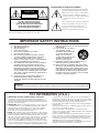 2
2
-
 3
3
-
 4
4
-
 5
5
-
 6
6
-
 7
7
-
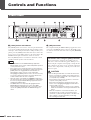 8
8
-
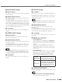 9
9
-
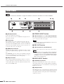 10
10
-
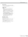 11
11
-
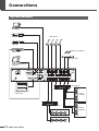 12
12
-
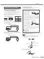 13
13
-
 14
14
-
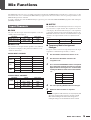 15
15
-
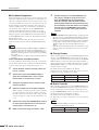 16
16
-
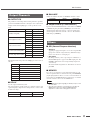 17
17
-
 18
18
-
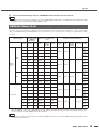 19
19
-
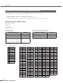 20
20
-
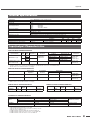 21
21
-
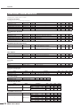 22
22
-
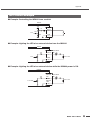 23
23
-
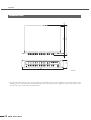 24
24
-
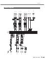 25
25
-
 26
26
-
 27
27
-
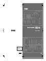 28
28


Yamaha IMX644 Manual de usuario
- Categoría
- Controladores de DJ
- Tipo
- Manual de usuario
en otros idiomas
- français: Yamaha IMX644 Manuel utilisateur
- italiano: Yamaha IMX644 Manuale utente
- English: Yamaha IMX644 User manual
- Deutsch: Yamaha IMX644 Benutzerhandbuch
- русский: Yamaha IMX644 Руководство пользователя
- Nederlands: Yamaha IMX644 Handleiding
- português: Yamaha IMX644 Manual do usuário
- dansk: Yamaha IMX644 Brugermanual
- polski: Yamaha IMX644 Instrukcja obsługi
- čeština: Yamaha IMX644 Uživatelský manuál
- svenska: Yamaha IMX644 Användarmanual
- Türkçe: Yamaha IMX644 Kullanım kılavuzu
- suomi: Yamaha IMX644 Ohjekirja
- română: Yamaha IMX644 Manual de utilizare
Artículos relacionados
-
Yamaha IMX644 El manual del propietario
-
-
Yamaha V3 El manual del propietario
-
-
-
-
-
-
-