Broan 88000 Series Guía de instalación
- Categoría
- Campanas de cocina
- Tipo
- Guía de instalación

READ AND SAVE
THESE INSTRUCTIONS
88000 SERIES/MICROTEK
®
SYSTEM IV
CONVERTIBLE RANGE HOOD
INSTALLATION INSTRUCTIONS
INSTALLER: Leave This Manual With The Homeowner. HOMEOWNER: Use and Care Information on Page 5.
INSTALADOR: Deje este manual con el dueño de casa. DUEÑO DE CASA: Información del uso y mantenimiento en la página 6.
For Ductfree Installation:
Follow all general steps and:
purchase a 97007662 Microtek
®
System IV Filter
Kit, available from your Broan Distributor or online
at www.broan.com.
LEA Y CONSERVE
ESTAS INSTRUCCIONES
Para instalación sin conductos:
Siga todos los pasos generales y:
compre un juego de filtro 97007662 Microtek
®
Sistema IV,
disponible por parte de su distribuidor Broan o en línea en
www.broan.com.
SERIE 88000/MICROTEK
®
SISTEMA IV
INSTRUCCIONES PARA INSTALACION
DE CAPUCHA PARA ESTUFA
ELECTRICA CONVERTIBLE
WARNING
TO REDUCE THE RISK OF FIRE, ELECTRIC SHOCK, OR
INJURY TO PERSONS, OBSERVE THE FOLLOWING:
1. Use this unit only in the manner intended by the manu-
facturer. If you have questions, contact the manufacturer
at the address or telephone number listed in the warranty.
2. Before servicing or cleaning unit, switch power off at
service panel and lock the service disconnecting means
to prevent power from being switched on accidentally.
When the service disconnecting means cannot be locked,
securely fasten a prominent warning device, such as a tag,
to the service panel.
3. Installation work and electrical wiring must be done by a
qualified person(s) in accordance with all applicable codes
and standards, including fire-rated construction codes and
standards.
4. Sufficient air is needed for proper combustion and exhaust-
ing of gases through the flue (chimney) of fuel burning
equipment to prevent backdrafting. Follow the heating
equipment manufacturer’s guideline and safety standards
such as those published by the National Fire Protection
Association (NFPA), and the American Society for Heating,
Refrigeration and Air Conditioning Engineers (ASHRAE),
and the local code authorities.
5. When cutting or drilling into wall or ceiling, do not damage
electrical wiring and other hidden utilities.
6. To reduce the risk of fire or electric shock, do not use this
range hood with an additional speed control device.
7. Ducted fans must always be vented to the outdoors.
8. To reduce the risk of fire, use only metal ductwork.
9. Use with approved cord-connection kit only.
10. This unit must be grounded.
TO REDUCE THE RISK OF A RANGE TOP GREASE FIRE:
1. Never leave surface units unattended at high settings.
Boilovers cause smoking and greasy spillovers that may
ignite. Heat oils slowly on low or medium settings.
2. Always turn hood ON when cooking at high heat or when
cooking flaming foods.
3. Clean ventilating fans frequently. Grease should not be
allowed to accumulate on fan or filter.
4. Use proper pan size. Always use cookware appropriate
for the size of the surface element.
TO REDUCE THE RISK OF INJURY TO PERSONS IN THE
EVENT OF A RANGE TOP GREASE FIRE, OBSERVE THE
FOLLOWING:*
1. SMOTHER FLAMES with a close-fitting lid, cookie sheet,
or metal tray, then turn off the burner. BE CAREFUL TO
PREVENT BURNS. If the flames do not go out immedi-
ately, EVACUATE AND CALL THE FIRE DEPARTMENT.
2. NEVER PICK UP A FLAMING PAN — You may be burned.
3. DO NOT USE WATER, including wet dishcloths or towels
- violent steam explosion will result.
4. Use an extinguisher ONLY if:
A. You know you have a Class ABC extinguisher and
you already know how to operate it.
B. The fire is small and contained in the area where it
started.
C. The fire department is being called.
D. You can fight the fire with your back to an exit.
* Based on “Kitchen Fire Safety Tips” published by NFPA.
INTENDED FOR DOMESTIC
COOKING ONLY.
ADVERTENCIA
PARA REDUCIR EL RIESGO DE INCENDIO, DESCARGA ELEC-
TRICA, O LESIONES PERSONALES, CUMPLA CON LOS
SIGUIENTES PUNTOS:
1. Solamente use esta unidad de la manera propuesta por el
fabricante. Si tiene alguna pregunta, póngase en contacto con
el fabricante en la dirección o teléfono anotados en la garantía.
2. Antes de limpiar o de poner en servicio la unidad, apague
el interruptor en el panel de servicio, y asegure el panel de
servicio para evitar que se encienda accidentalmente. Cuando
el dispositivo para desconectar el servicio eléctrico no puede
ser cerrado con algún tipo de traba, sujete fuertemente al panel
de servicio, una etiqueta de advertencia prominente.
3. El trabajo de instalación y el cableado eléctrico deben llevarse a
cabo por personal calificado de acuerdo con todos los códigos
y las normas aplicables, incluyendo los códigos y normas de
construcción contra incendios.
4. Se requiere una cantidad de aire suficiente para la combustión
y escape de gases por la chimenea del equipo que quema
combustible para evitar la retrogresión de la llama. Siga las
especificaciones y estándares de seguridad del fabricante,
tales como los que publica la Asociación Nacional de Protección
Contra Incendios (NFPA por sus sigles en inglés), y la Sociedad
Americana de Ingenieros de Calefacción , Refrigeración y Aire
Acondicionado (ASHRAE), y los códigos de las autoridades
locales.
5. Cuando corte o taladre en una pared o cielo raso, no dañe
cableado eléctrico u otras instalaciones no visibles.
6. Para reducir el riesgo de incendio o de descarga eléctrica, no
utilice este ventilador con ningún dispositivo de una control de
velocidad de estado sólido adicional.
7. Los abanicos con ducto deberán siempre tener una salida hacia
el exterior.
8. Para reducir el riesgo de incendio, use sólo ductos de metal.
9. Uso con el kit aprobado del la conexión de la cuerda solamente.
10. Esta unidad se debe instalar con tierra efectiva.
PARA REDUCIR EL RIESGO DE INCENDIO DEBIDO A GRASA
ACUMULADA EN LAS HORNILLAS:
1. Nunca deje sin atender las unidades de superficie cuando
tengan ajustes altos. Los reboses pueden provocar humo
y derrames grasosos que se pueden incendiar. Caliente
lentamente el aceite en un ajuste bajo o medio.
2. Siempre ENCIENDA la campana cuando cocine con alta
temperatura o cuando cocine alimentos que se puedan
incendiar.
3. Limpie con frecuencia los ventiladores. No debe permitir que
la grasa se acumule en el ventilador ni en el filtro.
4. Utilice un sartén de tamaño adecuado. Siempre utilice el
utensilio adecuado al tamaño del elemento de superficie.
PARA REDUCIR EL RIESGO DE LESIONES PERSONALES EN
CASO DE INCENDIO DE GRASA EN LA SUPERFICIE DE LA
ESTUFA, OBSERVAR LO SIGUIENTE:*
1. Cubra y sofoque las llamas con una tapa ajustada, azafate
de hornear galletas, o un azafate de metal, y luego apague el
calentador. TENGA CUIDADO PARA EVITAR QUEMADURAS.
Si las llamas no se apagan inmediatamente, HAY QUE
EVACUAR Y LLAMAR LOS BOMBEROS.
2. NUNCA ALCE UNA SARTEN QUE TENGA LLAMAS - Usted
se puede quemar.
3. NO USE AGUA, incluyendo trapos lavaplatos mojados o toallas
- puede que ocurran explosiones de vapor violentas.
4. Use un extintor SOLAMENTE si:
A. usted sabe que tiene un extintor ABC y ya sabe usarlo.
B. el fuego es pequeño y está restringido al área donde
empezó.
C. se está llamando los bomberos.
D. usted puede tratar de apagar el fuego teniendo una salida
detrás suyo.
* Basado en "Kitchen Fire Safety Tips" publicado por la Asociación
Nacional de Protección Contra Incendios (NFPA).
PREVISTO PARA COCINAR
DOMÉSTICO SOLAMENTE.
Register your product online at: www.broan.com/register
Registre su producto en línea en: www.broan.com/register

MODEL 634 OR 644 ROOF CAP
TAPA PARA TECHO MODELO 634 O 644
MODEL 406 6" ROUND DUCT
MODELO 406 CONDUCTO REDONDO DE
15,24 CM (6 PULG.)
MODEL 411 3–1/4" X 10" TO 6"
ROUND DUCT TRANSITION
MODELO 411
TRANSICIÓN A CONDUCTO REDONDO
DE 8,26 CM X 25,40 CM A 15,24 CM
(3-1/4 X 10 PULG. A 6 PULG.)
FIG. 1A
FIG. 1B
FIG. 1C
MODEL 634 OR 644
ROOF CAP
TAPA PARA TECHO
MODELO 634 O 644
MODEL 401
3-1/4" X 10" DUCT
MODELO 401
CONDUCTO 8,26 CM X 25,40 CM
(3-1/4 X 10 PULG.)
FIG. 1D
FIG. 1E
MODEL 419
ADJUSTABLE ELBOW
MODELO 419
CODO AJUSTABLE
MODEL 411
3–1/4" X 10" TO 6"
ROUND DUCT TRANSITION
MODELO 411
TRANSICION A
CONDUCTO
REDONDO DE
8,26 CM X 25,40 CM A 15,24 CM
(3-1/4 X 10 PULG. A 6 PULG.)
MODEL 406
6" ROUND DUCT
MODELO 406
CONDUCTO RE-
DONDO
15,24 CM (6 PULG.)
MODEL 639 OR 649 WALL CAP
TAPA PARA PARED MODELO 639 O 649
MODEL 429 ELBOW
CODO MODELO 429
MODEL 401
3-1/4" X 10" DUCT
MODELO 401
CONDUCTO
8,26 CM X
25,40 CM
(3-1/4 X 10 PULG.)
MODEL 639 OR
649 WALL CAP
TAPA PARA
PARED MODELO
639 O 649
MODEL 641 WALL CAP
TAPA PARA PARED
MODELO 641
CUIDADO
1. Para el uso de interior solamente.
2. Para uso de ventilación general solamente. No lo
use para extraer materiales o vapores explosivos o
peligrosos.
3. Para evitar daño a los cojinetes del motor e impulsores
ruidosos y/o desequilibrados, mantenga la unidad de
potencia lejos de rocíos de yeso, polvo de construcción,
etc.
4. Este producto está equipado con un termostato que
puede activar el ventilador automáticamente. Para
reducir el riesgo de lesión, desconecte la potencia en
el panel de servicio y trábelo para evitar que ésta se
prenda automáticamente.
5. El motor de su capucha tiene una sobrecarga térmica
que apaga el motor automáticamente si éste se
sobrecalienta. El motor arranca de nuevo cuando se
enfría. Si el motor continúa apagándose y arrancando,
hay que hacerle servicio a la capucha.
6. Para atrapar impurezas de cocinado de la mejor
manera, la capucha de su estufa se debe montar
de 45,72 cm a 60,96 cm (18 - 24 pulg.) arriba de la
superficie de cocinado.
7. Por favor lea la etiqueta con especificaciones del
producto para más información y requisitos.
HERRAMIENTAS Y
MATE-
RIALES NECESARIOS
HERRAMIENTAS
q Taladro, eléctrico o de trinquete
q Gusanillo de taladro de hoja ancha de 3,18 cm
(1-1/4 pulg.)
q Destornilladores tipo phillips y tipo hoja
q Alicates
q Cinta para medir o regla y lápiz
Solamente para instalaciones con conductos:
q Sierra de hoja o sierra para yeso
q Tijeras para metal
MATERIALES
q Cableado eléctrico y artículos del tipo necesario para
cumplir con códigos locales
Solamente para instalaciones con conductos:
q Tapa para pared o techo
q Cemento para techo o masilla de calafateo
q Conductos y cinta de conductos
Solamente para instalaciones sin conductos:
q Un juego de dos paquetes de filtro 97007662 Mi-
crotek
®
Sistema IV
Solamente para instalación en gabinetes de cocina con fondo
que no está a nivel con el marco:
q Dos tiras de madera de 2,54 cm X 5,08 cm X 30,48 cm
(1 X 2 X 12 pulg. de tamaño aproximado que se pueden
conseguir localmente)
q Cuatro tornillos de cabeza plana de 3,18 cm (1-1/4 pulg.)
para madera para fijar las tiras al fondo del gabinete
2
CAUTION
1. For indoor use only.
2. For general ventilating use only. Do not use to
exhaust hazardous or explosive materials and
vapors.
3. To avoid motor bearing damage and noisy and/
or unbalanced impellers, keep drywall spray,
construction dust, etc. off power unit.
4. This product is equipped with a thermostat which
may start fan automatically. To reduce the risk of
injury, switch power off at service panel and lock
service panel to prevent power from being switched
on automatically.
5. Your hood motor has a thermal overload which
will automatically shut off the motor if it becomes
overheated. The motor will restart when it cools
down. If the motor continues to shut off and restart,
have the hood serviced.
6. For best capture of cooking impurities, your range
hood should be mounted 18-24" above the cooking
surface.
7. Please read specification label on product for
further information and requirements.
TOOLS AND
MATERIALS REQUIRED
TOOLS
q Drill, electric or ratchet drive
q 1-1/4” Spade bit
q Common head and phillips head screwdriver
q Pliers
q Tape measure or ruler and pencil
For Ducted Installations Only:
q Saber Saw or drywall saw
q Metal snips
MATERIALS
q Electrical wiring and supplies of type to comply with
local codes
For Ducted Installations Only:
q Roof or wall cap
q Roof cement or caulk
q Duct and duct tape
For Ductfree Installations Only:
q One two-pack 97007662 Microtek
®
System IV
Filter Kit
For Installation On Kitchen Cabinets With Recessed
Bottoms Only:
q Two 1” x 2” x 12” (approximate length) wood strips
(purchase locally)
q Four 1-1/4” long flat head wood screws (purchase
locally) to fasten strips to cabinet bottom
PLAN DUCTWORK
INSTALLATION
For Ducted Installations Only:
Begin planning ductwork by deciding where duct
will run between hood and outside. For best per-
formance, use shortest possible duct run and a
minimum number of elbows. In more complex situ-
ations, 3-1/4” x 10” duct can be converted to round
duct by means of a transition. FIGS 1A - 1E show
several choices.
FIG. 1A: Ducting directly through outside wall. If
wall cap is used directly off back of hood, check to
make sure that damper flap in damper/duct con-
nector on hood does not interfere with damper flap
in wall cap. If it does, remove flap on hood damper/
duct connector.
FIG. 1B: At times it will be easier to run duct vertically
and use an elbow.
FIG. 1C: Ducting straight up through roof using 3-1/4”
x 10” duct. For single story installations.
FIG. 1D: Straight up through roof using round duct.
FIG. 1E: Ducting between ceiling joists for multi-story
installations or through soffits above cabinets where
soffit connects to outside walls.

CENTER LINE
LINEA CEN-
TRAL
PREPARE HOOD
1. Unpack hood and check contents. You should
receive:
1 - assembled hood
1 - plastic bag, containing:
4 - 7/8” wood screws for mounting hood to
cabinet
2 - 1/4” black sheet metal screws for mounting
damper/duct connector to hood
2 - aluminum filters
1 - damper/duct connector
For Ductfree Installations Only:
Discard damper/duct connector and two black sheet
metal screws.
For Steps 2 - 6 below, refer to FIG. 2.
2. Set hood upside down and remove bottom cover
and screws.
3. Remove filters.
4. Remove wiring box cover and screws.
5. Remove blower assembly:
a.) Unplug blower.
b.) Loosen knurled nuts on mounting rods and slip
rods out of blower mounting brackets. Do not
remove nuts completely from rods.
c.) Lift out blower and set blower aside.
CAUTION
DO NOT GRASP BLOWER BY BLOWER WHEELS.
WHEELS MAY BE DAMAGED.
6. Remove light lens. Squeeze sides of lens toward
center of hood and lift lens out.
7. Remove either top or rear electrical knockout. (FIG.
3)
For Ducted Installations Only:
1. Remove either top or rear duct knockout. (FIG. 3)
2. Fasten damper/duct connector to hood over
opening. Use two black sheet metal screws
provided in parts bag. (FIG. 3)
PREPARE THE
INSTALLATION LOCATION
NOTE
IF DISTANCE BETWEEN WALL AND FRONT
OF CABINET FACE FRAME IS MORE THAN
12”, THERE WILL BE A GAP BETWEEN BACK
OF HOOD AND WALL. THIS IS NORMAL. TOP
FRONT EDGE OF HOOD SHOULD BE FLUSH
WITH FRONT OF CABINET FACE FRAME. OMIT
STEP 1 IF HOOD WILL BE INSTALLED UNDER
CABINETS WITH FLUSH BOTTOM.
1. For Cabinets With Recessed Bottoms ONLY: (FIG.
4)
Install wood filler strips on each side of recessed
area under cabinet. Use two 1” x 2” strips cut to
length (use thicker strips if necessary). Fasten
strips with wood screws about 3” in from each end.
2. Measure and mark the following: (FIG. 5)
a.) electrical wiring opening
For Ducted Installations Only:
b.) duct opening
3. Cut duct opening in wall or cabinet bottom.
4. Drill 1-1/4” electrical wiring opening in wall or
cabinet bottom.
5. Hold hood up against cabinet bottom and trace
keyhole slots onto cabinet bottom or filler strips. For
larger hoods: Two 1/4” dia. holes are provided for
secure mounting. They are located in top of hood
approx. 8” each side of center. Add filler strips for
these as necessary. Avoid blocking hood’s vertical
electrical knockout.
6. Screw four 7/8” wood screws from parts bag into
exact center of narrow end of keyhole slots marked
on cabinet bottom. Allow 3/8” of screws to project,
so hood can be fitted into place later.
7. Run electric wiring through hole drilled in wall or
cabinet. Provide 6” leads and install proper connec-
tor for type of wire used.
FIG. 2
STEP 2
PASO 2
FIG. 3
HINGE PINS
PASADORES
DE GOZNE
HORIZONTAL DUCTING*
CONDUCTO HORIZONTAL*
FIG. 4
3"
7,62 CM (3 PULG.)
WIDTH OF RANGE HOOD
ANCHURA DE LA CAPUCHA
PARA LA ESTUFA
DUCT OPENINGS*
ABERTURAS DEL
CONDUCTO*
ELECTRICAL
WIRING
OPENING
ABERTURA PARA
CABLEADO
ELECTRICO
3"
STEP 3
PASO 3
STEP 4
PASO 4
STEP 6
PASO 6
STEP 5
PASO 5
ELECTRICAL KNOCKOUTS
DISCOS REMOVIBLES
PARA LO ELECTRICO
VERTICAL DUCTING*
CONDUCTO VERTICAL*
DUCT KNOCKOUTS*
PIEZAS REMOVIBLES
DEL CONDUCTO*
* FOR DUCTED INSTALLATIONS ONLY.
* SOLAMENTE PARA INSTALACIONES CON CONDUCTOS.
7,62 CM (3 PULG.)
CUT STRIPS TO FIT
CORTE LAS TIRAS AL TAMAÑO
DESEADO
PLANIFICANDO LA
INSTALACION DE
LOS CONDUCTOS
Solamente para instalaciones con conductos:
Comience la planificación de los conductos decidiendo
la ruta desde la capucha hasta el exterior. Para el mejor
desempeño, use la ruta más directa y el menor número
de codos. En situaciones más complejas, conductos
de 8,26 cm X 25,40 cm (3-1/4 X 10 pulg.) se pueden
convertir a conductos redondos usando un adaptador.
Las Figs. 1A - 1E le muestran varias opciones.
FIG. 1A: conductos directamente a través de la pared
exterior. Si se usa una tapa de pared desde la parte
trasera de la capucha, verifique que la aleta del amor-
tiguador en la unión del amortiguador/conducto en la
capucha no interfiera con la aleta del amortiguador en
la tapa para pared. Si interfiere, quite la aleta en la unión
amortiguador/conducto de la capucha.
FIG. 1B: a veces es mejor usar conducto vertical y usar
un codo.
FIG. 1C: conductos verticales a través del techo con
conductos de 8,26 cm X 25,40 cm (3-1/4 X 10 pulg.).
Para instalaciones de un piso.
FIG.1D: vertical hasta el techo con un conducto redondo.
FIG. 1E: conductos entre las vigas del cielo raso para
instalaciones de varios pisos o a través de sófitos ar-
riba de gabinetes donde los sófitos llegan a las paredes
exteriores.
PREPARANDO
LA CAPUCHA
1. Saque la capucha y verifique su contenido. Usted debe
tener:
1 - capucha armada
1 - bolsa plástica que contiene:
4 - tornillos para madera de 2,22 cm (7/8 pulg.) para
montar la capucha al gabinete
2 - tornillos negros de 0,64 cm (1/4 pulg.) para lámina
de metal para montar la unión del amortiguador/
conducto a la capucha
2 - filtros de aluminio
1 - unión del amortiguador/conducto
Solamente para instalaciones sin conductos:
Deseche la unión del amortiguador/conducto y los dos
tornillos negros para lámina de metal.
Para pasos 2 - 6 abajo, referirse a FIG. 2.
2. Coloque la capucha cabeza abajo y quite la tapa inferior
y los tornillos.
3. Saque los filtros.
4. Saque la tapa de la caja de conexiones y los tornillos.
5. Saque el conjunto del soplador:
a.) Desenchufe el soplador.
b.) Afloje las tuercas nudosas de las varas
de montaje y deslice éstas del soporte de
montaje del soplador. No saque las tuercas
completamente de las varas.
c.) Alce el soplador y póngalo a un lado.
CUIDADO
NO ALCE EL SOPLADOR POR SUS RUEDAS. ESTAS
SE PUEDEN DAÑAR.
6. Saque el lente de luz. Apriete los lados del lente hacia
el centro de la capucha y sáquelo.
7. Saque el disco removible superior o el trasero. (FIG. 3)
Solamente para instalaciones con conductos:
1. Saque el disco removible de la parte superior, o el
trasero. (FIG. 3)
2. Fije la unión del amortiguador/conducto a la
capucha sobre la abertura. Use dos tornillos negros
para lámina de metal que se suministran en la bolsa
de piezas. (FIG. 3)
* FOR DUCTED INSTALLATIONS ONLY.
* SOLAMENTE PARA INSTALACIONES CON CONDUCTOS.
3

INSTALL THE DUCTWORK
For Ducted Installations Only:
NOTE
THESE INSTRUCTIONS WILL FOLLOW
THE PLANS MADE ON PAGE 2. START ON
THE OUTSIDE AND WORK BACK TOWARD
HOOD. FOLLOW APPROPRIATE DIREC-
TIONS FOR TYPE OF DUCT SYSTEM YOU
ARE INSTALLING.
WALL CAPS (FIG. 6)
Use a saber saw to cut a hole slightly larger than duct
so duct will line up easily with hood. Install casing
strips on outside walls finished in siding. Assemble
the ductwork and tape all joints. Run ductwork back
to hood. Fasten wall cap to last section of duct and
nail or screw cap to wall. Seal all around flange on
wall cap with caulking compound. Make sure that
enough duct runs into the room so that the duct will
overlap the damper/duct connector by 3/4” when
the hood is installed.
ROOF CAPS (FIG. 7)
Cut hole in roof slightly larger than duct so duct will
line up easily with hood. Trim shingles around hole
so that they will fit snugly around hood of cap when
cap is installed. Assemble the ductwork and tape
all joints. Run the ductwork down to hood. Trim duct
parallel to roof pitch, leaving 3/4” of duct projecting
above roof (FIG. 7A). Seal all around duct with roof
cement. (FIG 7B) Install roof cap, inserting back
edge of cap under shingles. (FIG 7C) Seal around
roof cap with roof cement and seal all nail heads and
shingles which were cut or lifted. (FIG. 7D)
Make sure that enough duct runs into the room so
that the duct will overlap the damper/duct connector
by 3/4” when the hood is put into place.
INSTALL HOOD
1. Position hood so that: (FIG. 8)
a.) electrical wiring runs through opening in top or
back of hood.
b.) large part of keyhole slots fit over hood mount-
ing screws
For Ducted Installations Only:
c.) damper/duct connector slides into ductwork.
2. Push hood back so that mounting screws slide into
narrow end of keyhole slots. When mounting larger
hoods, run (2) screws through the 1/4” dia. holes
(in hood top and 8” each side of center) and into
the cabinet bottom or added filler strips. Tighten all
screws firmly.
3. Install locknut on electrical connector and tighten
securely.
4. Make electrical connections. Connect white to
white, black to black, and green or bare wire to
green ground screw. (FIG. 9)
5. Replace wiring box cover and screws. Make sure
that wires are not pinched between cover and hood.
6. Install two 75 watt max. bulbs, or one 75 watt bulb
and one 25 watt bulb for night-light use. Install 25
watt bulb in righthand socket.
For Ducted Installations Only:
Reinstall blower. Do not grasp blower by blower
wheels. Position blower so that blower discharge
lines up with damper/duct connector and slip rods
into mounting brackets on blower assembly. (FIG. 10)
Tighten knurled nuts securely, and plug in blower.
For Ductfree Installations Only:
1. Reinstall blower. Do not grasp blower by
blower wheels. Move blower mounting rods to
front holes in hood support channels. (FIG. 11)
Position blower so that blower discharge lines
up with louvered opening on hood front.
2. Slip rods into mounting brackets and tighten
knurled nuts securely. Plug in blower.
3. Remove louver cover on control panel. Pry cover
off with screwdriver or knife.
7. Reinstall bottom cover and screws. (FIG. 2)
FIG. 5
FIG. 6*
FIG. 7B*
FIG. 7A*
PREPARANDO EL
LUGAR DE INSTALACION
NOTA
SI LA DISTANCIA ENTRE LA PARED Y EL FRENTE
DEL MARCO DEL GABINETE ES MAS DE 30,48 CM
(12 PULG.) HABRA UN ESPACIO VACIO ENTRE LA
PARTE DE ATRAS DE LA CAPUCHA Y LA PARED.
ESTO ES NORMAL. EL BORDE FRONTAL SUPERIOR
DE LA CAPUCHA DEBE ESTAR A NIVEL CON EL FR-
ENTE DEL MARCO DEL GABINETE. OMITA PASO 1 SI
LA CAPUCHA SE VA A INSTALAR BAJO GABINETES
CON FONDO A NIVEL CON EL MARCO.
1. SOLAMENTE para gabinetes con fondo que no está a
nivel con el marco: (FIG. 4)
Instale las tiras de madera para relleno en cada lado
del área que no está a nivel con el marco bajo el
gabinete. Use dos tiras de 2,54 cm X 5,08 cm (1 X 2
pulg.) del tamaño apropiado (use tiras más gruesas si
es necesario). Fije las tiras con tornillos para madera
como a 7,62 cm (3 pulg.) de cada extremo.
2. Mida y marque lo siguiente: (FIG. 5)
a) abertura para cableado eléctrico
Solamente para instalaciones con conductos
b) abertura del conducto
3. Haga la abertura del conducto en la pared o al fondo
del gabinete
4. Taladre una abertura de 3,18 cm (1-1/4 pulg.) para
cableado eléctrico en la pared o al fondo del gabinete.
5. Sostenga la capucha contra el fondo del gabinete y
trace ranuras como ojo de llave en el fondo del gabinete
o en las tiras de relleno. Para capuchas más grandes:
se suministran dos agujeros de 0,64 cm (1/4 pulg.)
de diámetro para una instalación segura. Están en la
parte superior de la capucha aproximadamente 20,32
cm (8 pulg.) a cada lado del centro. Agregue tiras de
relleno para estos según sea necesario. Evite taparle a
la capucha el disco removible vertical para lo eléctrico.
6. Atornille cuatro tornillos para madera de 2,22 cm (7/8
pulg.) de la bolsa de piezas exactamente en el centro del
extremo angosto de la figura como ojo de llave que se
trazó en el fondo del gabinete. Deje 0,95 cm (3/8 pulg.)
de los tornillos sin atornillar para montar la capucha en
su lugar más tarde.
7. Pase cableado eléctrico por el agujero que se taladró en
la pared o gabinete. Deje 15,24 cm (6 pulg.) de cable e
instale el conector apropiado para el tipo de cable que
se usa.
INSTALANDO
LOS CONDUCTOS
Solamente para instalaciones con conductos:
NOTA
ESTAS INSTRUCCIONES SIGUEN LA PLANIFI-
CACIÓN QUE SE HIZO EN PÁGINA 3. EMPIECE
POR EL EXTERIOR Y TRABAJE HACIA LA CA-
PUCHA. SIGA LAS DIRECCIONES APROPIADAS
PARA EL SISTEMA DE CONDUCTOS QUE USTED
ESTA INSTALANDO.
TAPAS PARA PARED (FIG. 6)
Use una sierra de hoja para cortar un agujero un poco
más grande que el conducto para que éste se alinee
fácilmente con la capucha. Instale tiras de contramarco
en las paredes exteriores que tienen acabado en chapas
de forrado. Arme los conductos y forre todas las uniones
con cinta. Instale conductos hasta la capucha. Fije la tapa
para pared a la última sección del conducto y clave o
atornille la tapa a la pared. Selle bien alrededor del borde
de la tapa en la pared con masilla de calafateo. Verifique
que haya suficiente conducto dentro de la habitación
para que éste calce sobre la unión del amortiguador/
conducto con un borde de 1,91 cm (3/4 pulg.) cuando
se instale la capucha.
TAPAS PARA TECHO (FIG. 7)
Haga un agujero en el techo un poco más grande que el
conducto para que éste se alinee bien con la capucha.
Recorte las chapas alrededor del agujero para que calcen
de una manera compacta con la capucha de la tapa cu-
ando ésta se instale. Arme los conductos y forre todas las
uniones con cinta. Lleve los conductos hasta la capucha.
Recórtelos de una forma paralela a la inclinación del te-
cho, dejando 1,91 cm (3/4 pulg.) de conducto por encima
del techo (FIG. 7A). Selle todo alrededor del conducto con
cemento para techo. (FIG. 7B). Instale la tapa para techo,
FRONT OF CABINET FRENTE DEL GABINETE
1/8"
0,32
CM
HORIZONTAL DUCT OPENING*
ABERTURA CONDUCTO HORIZONTAL*
3–7/8"
9,84
CM
3/4"
1,90 CM
* FOR DUCTED INSTALLATIONS ONLY.
* SOLAMENTE PARA INSTALACIONES CON CONDUCTOS.
VERTICAL DUCT OPENING*
ABERTURA CONDUCTO VERTICAL*
CABINET BOTTOM FONDO DEL CABINETE
BACK WALL PARED TRASERA
9" 22,86 CM
9" 22,86 CM
10-5/8"
26,99
CM
6-7/8"
17,46
CM
6–1/4"
15,87 CM
6–1/4"
15,87 CM
7–1/2"
19,05 CM
9–7/8"
25,08
CM
* FOR DUCTED INSTALLATIONS ONLY.
* SOLAMENTE PARA INSTALACIONES CON CONDUCTOS.
FIG. 8
* FOR DUCTED INSTALLATIONS
ONLY.
* SOLAMENTE PARA INSTALA-
CIONES CON CONDUCTOS.
PLASTIC ROOF
CEMENT
CEMENTO PLASTICO
PARA TECHO
3/4"
1,91 CM
(3/4
PULG.)
* FOR DUCTED INSTALLATIONS
ONLY.
* SOLAMENTE PARA INSTALA-
CIONES CON CONDUCTOS.
* FOR DUCTED INSTALLATIONS
ONLY.
* SOLAMENTE PARA INSTALA-
CIONES CON CONDUCTOS.
FIG. 7C* FIG. 7D*
DO NOT CAULK AROUND BOTTOM
OF FLANGE FOR DRAINAGE
NO PONGA MASILLA ALREDEDOR
DE LA PARTE INFERIOR DEL
BORDE PARA DRENAJE
NAIL
CLAVO
* FOR DUCTED INSTALLATIONS
ONLY.
* SOLAMENTE PARA INSTALA-
CIONES CON CONDUCTOS.
3/8"
0,95 CM
6–1/4"
15,87 CM
6–1/4"
15,87 CM
7–1/2"
19,05 CM
1 –1/2"
3,81 CM
1 –1/2"
3,81 CM
ELECTRICAL LINE
LINEA ELECTRICA
4

For Ducted Installations Only:
Reinstall aluminum filters. Make sure tabs are toward
outside and bottom. (FIG. 12)
For Ductfree Installations Only:
1. Snap aluminum filter onto front of Microtek
®
System IV filter. (FIG. 13) Make sure that tab
on aluminum filter lines up with finger pull on
Microtek
®
filter.
2. Push filter assembly into hood. Flaps on filter
will flex against top and sides of opening. (FIG.
14) Push assembly up until bottom of assembly
clears lip on bottom cover. Insert bottom of filter
and pull assembly down, collapsing pull ring
against aluminum filters.
8. Turn on power and check operation of hood.
USE AND CARE
CONTROLS
BLOWER - "SPEED"
Infinite speed slide control adjusts blower speed and
sound level for quiet operation
BLOWER - "ON"
Turns blower ON and OFF.
When this control is turned ON, blower will operate at
preset speed of slide control.
LIGHT
Three-position switch
• First position (Normal) - Turns both bulbs ON.
• Second position (Night Light) - Turns right-side bulb
ON.
• Third position (OFF) - Turns both bulbs OFF.
DO NOT install bulbs rated higher than 75 watts.
Install a smaller bulb on the right for a night light.
HEAT SENTRY™
Your hood is equipped with a Heat Sentry™ thermostat.
This thermostat is a device that will turn on or speed
up the blower if it senses excessive heat above the
cooking surface.
1) If blower is OFF - it turns blower ON to HIGH speed.
2) If blower is ON at a lower speed setting - it turns
blower up to HIGH speed.
When the temperature level drops to normal, the blower
will return to its original setting.
FILTER CARE
Remove each filter by grasping the tab at the bottom of
filter, lifting up and swinging filter out to the side.
ALUMINUM FILTERS
Clean filters frequently in a detergent solution. They
are dishwasher safe.
DUCTFREE MICROTEK
®
FILTERS
The aluminum filter is the only washable part of the
Microtek
®
System IV filter. Snap it out of its frame and
clean it in a detergent solution or dishwasher.
The particle filter is not washable. It should last up to
twelve months with normal use.
CLEANING
Do not allow an excessive accumulation of grease. Use
a mild detergent suitable for painted surfaces. DO NOT
USE ABRASIVE CLOTH, STEEL WOOL PADS, OR
SCOURING POWDERS. Vacuum blower to clean. Do
not immerse blower in water.
HOW TO AVOID A COMMON RANGE-TOP
GREASE FIRE
• Your range hood provides a protective barrier
between the cooking surface and the cabinets.
• Keep fan, filters and grease laden surfaces
CLEAN according to instructions.
• Always turn hood ON when cooking at high heat
to keep the cooking area and the hood cooler.
• Use high heat settings only when necessary.
• Never leave cooking surface unattended. Boil-
over causes smoking and greasy spillovers that
may ignite.
• Always use adequate-sized utensils.
• If preparing flaming foods, such as Cherries Ju-
bilee, always turn hood ON to HIGH to prevent
a high heat situation which can cause damage
or fire.
HOW TO EXTINGUISH A COMMON RANGE-TOP
GREASE FIRE
• Never pick up a flaming pan. If dropped, flames
can spread quickly.
FIG. 9
BLACK NEGRO
BLACK NEGRO
WHITE BLANCO
WHITE BLANCO
GREEN
WHITE BLANCO
BLACK NEGRO
FIG. 10*
FIG. 11**
BLOWER DISCHARGE
SALIDA DEL SOPLADOR
Solamente para instalaciones con conductos:
metiendo su borde trasero bajo las chapas. (FIG.
7C). Selle alrededor de la tapa para techo con ce-
mento para techo y selle todas las cabezas de clavos
y chapas que se cortaron o levantaron. (FIG. 7D)
Verifique que haya suficiente conducto dentro de la
habitación para que éste calce sobre la unión del amor-
tiguador/conducto con un borde de 1,91 cm (3/4 pulg.)
cuando se instale la capucha.
INSTALANDO LA
CAPUCHA
1. Coloque la capucha tal que: (FIG. 8)
a.) el cableado eléctrico pase por la abertura en la
parte superior o trasera de la capucha.
b.) la parte ancha de las figuras como ojo de llave
calcen sobre los tornillos de montaje de la capucha.
Solamente para instalaciones con conductos:
c) la unión del amortiguador/conducto se deslice
dentro del conducto.
2. Empuje la capucha hacia atrás para que los tornillos de
montaje se deslicen dentro de la parte angosta de las
ranuras como ojo de llave. Cuando se monten capuchas
más grandes, pase (2) tornillos por los agujeros de 0,64
cm (1/4 pulg.) de diámetro (en la parte superior de la
capucha y a 20,32 cm (8 pulg.) a cada lado del centro)
y dentro del fondo del gabinete o tiras de relleno que se
hayan agregado. Atornille todos los tornillos firmemente.
3. Instale la tuerca de tranca en el conector eléctrico y
asegúrela firmemente.
4. Haga las conexiones eléctricas. Conecte blanco con
blanco, negro con negro, y cable verde o desnudo al
tornillo verde de tierra. (FIG. 9).
5. Coloque de nuevo la tapa de la caja de conexiones y
tornillos. Verifique que no haya cables atrapados entre
la tapa y la capucha.
6. Ponga dos bombillas máximo 75 vatios, o uno de 75
vatios y uno de 25 vatios para uso como luz nocturna.
Instale el bombillo de 25 vatios en el receptáculo a mano
derecha.
Solamente para instalaciones con conductos:
Coloque de nuevo el soplador. No alce el soplador por
sus ruedas. Colóquelo de tal manera que el escape
del soplador se alinee con la unión del amortiguador/
conducto y deslice las varas dentro de los soportes de
montaje en el conjunto del soplador (FIG. 10) Asegure
las tuercas nudosas firmemente, y enchufe el soplador.
Solamente para instalaciones sin conductos:
1. Coloque de nuevo el soplador. No alce el soplador
por sus ruedas.Cambie las varas de montaje del
soplador a los agujeros del frente en los canales de
soporte de la capucha.(FIG. 11) Coloque el soplador
de tal modo que su salida esté en línea con la
abertura con rejillas en el frente de la capucha
2. Deslice las varas dentro de los soportes de montaje
y fije las tuercas nudosas firmemente. Enchufe el
soplador.
3. Saque la cubierta de rejilla en el panel de control.
Con un destornillador o cuchillo saque la cubierta.
7. Vuelva a colocar la cubierta del fondo y tornillos (FIG. 2).
Solamente para instalaciones con conductos:
Coloque de nuevo los filtros de aluminio. Verifique que
las lengüetas estén hacia el fondo y hacia afuera. (FIG. 12).
Solamente para instalaciones sin conductos:
1. Encaje el filtro de aluminio enfrente del filtro Sistema
IV Microtek
®
. (FIG. 13). Verifique que la lengüeta en
el filtro de aluminio esté en línea con el anillo de tirar
con el dedo en el filtro Microtek
®
.
2. Empuje el conjunto del filtro dentro de la capucha.
Los bordes en el filtro se doblan contra la parte
superior y lados de la abertura. (FIG. 14). Empuje
el conjunto hasta que su fondo pase el labio de la
cubierta del fondo. Meta el fondo del filtro y hale el
conjunto hacia abajo, empujando el anillo de tirar
con el dedo contra los filtros de aluminio.
8. Reconecte la potencia y verifique el funcionamiento de
la capucha.
FIG. 12*
3
2
1
* FOR DUCTED INSTALLATIONS ONLY
* SOLAMENTE PARA INSTALACIONES CON CONDUCTOS.
VERDE
GROUND
(BARE OR
GREEN WIRE)
CABLE DE
TIERRA
(VERDE O DES-
CUBIERTO)
BLOWER DISCHARGE
SALIDA DEL SOPLADOR
HORIZONTAL DUCTING
CONDUCTO HORIZONTAL
VERTICAL DUCTING
CONDUCTO VERTICAL
* FOR DUCTED INSTALLATIONS ONLY
* SOLAMENTE PARA INSTALACIONES CON CONDUCTOS.
** FOR DUCTFREE INSTALLATIONS ONLY
** SOLAMENTE PARA INSTALACIONES SIN CONDUCTOS.
LOUVER COVER
TAPA DE REJILLA
5
BLACK NEGRO
GREEN
VERDE

USO Y MANTENIMIENTO
CONTROLES
SOPLADOR - "SPEED" (VELOCIDAD)
El control infinito deslizable de velocidad ajusta la veloci-
dad del soplador y el nivel de sonido para funcionamiento
silencioso.
SOPLADOR "ON" (ENCENDIDO)
Enciende (ON) y apaga (OFF) el soplador
Cuando este control está en ON, el soplador funciona a la
velocidad prefijada por el control deslizable.
LUZ
Conmutador de tres posiciones.
• Primera posición (Normal) - Enciende ambos bombillas.
• Segunda posición (Luz nocturna) - Enciende el bombillo
derecho.
• Tercera posición (OFF) (Apagado) - Apaga ambos bombil-
las.
NO instale bombillas de más de 75 vatios.
Instale un bombillo más pequeño para luz nocturna.
HEAT SENTRY™ (SENTINELA DE CALOR)
Su capucha está equipada con un termostato Heat Sentry™.
Este termostato es un aparato que enciende el soplador o
aumenta su velocidad si detecta un calor demasiado alto
sobre la superficie de cocinado.
1) si el soplador está en OFF (apagado)- lo cambia a ON
(encedido) en velocidad HIGH (alta).
2) si el soplador está en ON (encendido) en una velocidad
más baja - cambia el soplador a velocidad HIGH (alta)
Cuando la temperatura disminuye a lo normal, el soplador
regresa a su nivel original.
MANTENIMIENTO DE LOS FILTROS
Saque cada filtro tomándolo de la lengüeta en la parte
inferior, sacándolo hacia arriba y hacia un lado.
FILTROS DE ALUMINIO
Limpie los filtros con frecuencia en una solución de deter-
gente. Se pueden lavar en máquinas lavaplatos.
FILTROS MICROTEK
®
SIN CONDUCTOS
El filtro de aluminio es la única pieza lavable del filtro Mi-
crotek
®
Sistema IV. Sáquelo de su marco y límpielo en una
solución de detergente o en una máquina lavaplatos.
El filtro de partículas no es lavable. Debe durar hasta doce
meses bajo uso normal.
LIMPIEZA
No permita que se haga una acumulación alta de grasa. Use
un detergente suave que sea adecuado para superficies
pintadas. NO USE TELAS ASPERAS, ESPONJILLAS DE
ACERO, O POLVOS DE LIMPIAR ASPEROS. Limpie con
aspiradora. No meta el soplador dentro del agua.
FIG. 13**
** FOR DUCTFREE INSTALLATIONS ONLY.
** SOLAMENTE PARA INSTALACIONES SIN CONDUCTOS.
FIG. 14**
3
2
1
** FOR DUCTFREE INSTALLATIONS ONLY.
** SOLAMENTE PARA INSTALACIONES SIN CONDUCTOS.
FIG. 15
FIG. 16: WIRING DIAGRAM
DIAGRAMA DE CABLEADO
120 VAC LINE IN
120 VCA
LINEA DE ENTRADA
WHITE BLANCO
WHITE BLANCO
BLACK NEGRO
BLACK NEGRO
THERMOSTAT
TERMOSTATO
A
BLACK NEGRO
B
C
B
A
A
B
BLACK NEGRO
WHITE BLANCO
GREEN VERDE
WHITE
BLANCO
M
A WHITE / BLANCO
B BLACK / NEGRO
C ORANGE / ANARANJADO
1
YELLOW AMARILLO
2
4
5
6
8
9
10
CONTROL BOARD
(SYMBOLIC)
TARJETA DE
CONTROL (SIM-
BOLICO)
LAMP "B"
LAMPARA "B"
LAMP "A"
LÁMPARA "A"
6
• DO NOT USE WATER! A violent steam explo-
sion may result. Wet dishcloths or towels are
also dangerous.
• Smother flames with a close fitting lid, cookie
sheet or metal tray.
• Flaming grease can also be extinguished with
baking soda or a multi-purpose dry chemical
extinguisher.
• Turn off surface units - If you can do so without
getting burned.
WIRING DIAGRAM
NOTE: If any of the original wire on the hood has to
be replaced, use wire having equivalent insulation and
temperature rating (105°C Thermoplastic AWM, U.L.
Listed). (FIG. 16)

COMO EVITAR UN INCENDIO COMUN DE GRASA EN
LA SUPERFICIE DE LA ESTUFA
• Su capucha de estufa proporciona una barra
protectora entre la superficie de cocinado y los
gabinetes.
• Mantenga limpios el ventilador, filtros y superficies
donde se pueda acumular la grasa. Haga la limpieza
de acuerdo a las instrucciones.
• Cuando cocina a temperatura elevada active
siempre la capucha para mantener ésta y el área
de cocinado a temperaturas más bajas.
• Use los rangos de temperatura elevados solamente
cuando sea necesario.
• Nunca deje de prestar atención al área donde
se está cocinando. Derrames causados al hervir
producen humo y derrames de grasa que pueden
hacer llamas.
• Use siempre utensilios de tamaño adecuado.
• Si está preparando platos que tienen llamas, como
los que usan licores ardiendo, encienda siempre la
capucha (ON) y ajústela en alta (HIGH) para evitar
una situación con el calor que pueda desarrollar
daño o fuego.
COMO APAGAR UN INCENDIO COMUN DE GRASA
EN LA SUPERFICIE DE LA ESTUFA
• Nunca alce una sartén que está en llamas. Si se ha
caído, las llamas se pueden esparcir rápidamente.
• NO USE AGUA! Puede ocurrir una explosión
violenta de vapor. Telas lavaplatos mojadas o toallas
también son peligrosas.
• Cubra y sofoque las llamas con una tapa ajustada,
azafate de hornear galletas, o azafate de metal.
• Grasa en llamas también se puede apagar con
bicarbonato de soda o un extintor de químico seco
para uso general.
• Apague las unidades en la superficie de cocinado
- si es que lo puede hacer sin quemarse.
DIAGRAMA DE CABLEADO
NOTA: si hay que cambiar alguno del cableado original en
la capucha, use cable que tenga el aislamiento y aguante
de temperatura equivalentes (Termoplástico AWM 105°C,
con registro de U.L.) (FIG. 16)
7
BROAN-NUTONE ONE YEAR LIMITED WARRANTY
Broan-NuTone warrants to the original consumer purchaser of its
products that such products will be free from defects in materials or
workmanship for a period of one year from the date of original pur-
chase. THERE ARE NO OTHER WARRANTIES, EXPRESS OR IMPLIED,
INCLUDING, BUT NOT LIMITED TO, IMPLIED WARRANTIES OF MER-
CHANTABILITY OR FITNESS FOR A PARTICULAR PURPOSE.
During this one-year period, Broan-NuTone will, at its option, repair or
replace, without charge, any product or part which is found to be defec-
tive under normal use and service.
THIS WARRANTY DOES NOT EXTEND TO FLUORESCENT LAMP
STARTERS, TUBES, HALOGEN AND INCANDESCENT BULBS, FUSES,
FILTERS, DUCTS, ROOF CAPS, WALL CAPS AND OTHER ACCESSO-
RIES FOR DUCTING. This warranty does not cover (a) normal mainte-
nance and service or (b) any products or parts which have been subject
to misuse, negligence, accident, improper maintenance or repair (other
than by Broan-NuTone), faulty installation or installation contrary to
recommended installation instructions.
The duration of any implied warranty is limited to the one-year period
as specified for the express warranty. Some states do not allow limita-
tion on how long an implied warranty lasts, so the above limitation may
not apply to you.
BROAN-NUTONE’S OBLIGATION TO REPAIR OR REPLACE, AT BROAN-
NUTONE’S OPTION, SHALL BE THE PURCHASER’S SOLE AND EXCLU-
SIVE REMEDY UNDER THIS WARRANTY. BROAN-NUTONE SHALL
NOT BE LIABLE FOR INCIDENTAL, CONSEQUENTIAL OR SPECIAL
DAMAGES ARISING OUT OF OR IN CONNECTION WITH PRODUCT USE
OR PERFORMANCE. Some states do not allow the exclusion or limita-
tion of incidental or consequential damages, so the above limitation or
exclusion may not apply to you.
This warranty gives you specific legal rights, and you may also have
other rights, which vary from state to state. This warranty supersedes
all prior warranties.
To qualify for warranty service, you must (a) notify Broan-NuTone at
the address or telephone number below, (b) give the model number
and part identification and (c) describe the nature of any defect in the
product or part. At the time of requesting warranty service, you must
present evidence of the original purchase date.
Broan-NuTone LLC, 926 W. State Street, Hartford, Wisconsin 53027
www.broan.com 800-558-1711
GARANTIA BROAN-NUTONE LIMITADA POR UN AÑO
Broan-NuTone garantiza al consumidor comprador original de sus productos
que dichos productos carecerán de defectos en materiales o en mano de
obra por un período de un año a partir de la fecha original de compra. NO
EXISTEN OTRAS GARANTIAS, EXPLICITAS O IMPLICITAS, INCLUYENDO,
PERO NO LIMITADAS A, GARANTIAS IMPLICITAS DE COMERCIALIZACION
O APTITUD PARA UN PROPOSITO PARTICULAR.
Durante el período de un año, y a su propio criterio, Broan-NuTone reparará
o reemplazará, sin costo alguno cualquier producto o pieza que se encuentre
defectuosa bajo condiciones normales de servicio y uso.
LA PRESENTE GARANTÍA NO CUBRE LOS TUBOS FLUORESCENTES NI
SUS ARRANCADORES, BOMBILLAS DE HALÓGENO E INCANDESCENTES,
FUSIBLES, FILTROS, CONDUCTOS, TAPONES DE TECHO O PAREDES
Y DEMÁS ACCESORIOS PARA CONDUCTOS. Esta garantía no cubre (a)
mantenimiento y servicio normales o (b) cualquier producto o piezas que
hayan sido utilizadas de forma errónea, negligente, que hayan causado un
accidente, o que hayan sido reparadas o mantenidas inapropiadamente
(por otras compañías que no sean Broan-NuTone), instalación defectuosa,
o instalación contraria a las instrucciones de instalación recomendadas.
La duración de cualquier garantía implícita se limita a un período de un año
como se especifica en la garantía expresa. Algunos estados no permiten
limitaciones en cuanto al tiempo de expiración de una garantía implícita,
por lo que la limitación antes mencionada puede no aplicarse a usted.
LA OBLIGACION DE BROAN-NUTONE DE REPARAR O REEMPLAZAR,
SIGUIENDO EL CRITERIO DE BROAN-NUTONE, DEBERA SER EL UNICO Y
EXCLUSIVO RECURSO LEGAL DEL COMPRADOR BAJO ESTA GARANTIA.
BROAN-NUTONE NO SERA RESPONSABLE POR DAÑOS INCIDENTALES,
CONSIGUIENTES, O POR DAÑOS ESPECIALES QUE SURJAN A RAIZ DEL
USO O DESEMPEÑO DEL PRODUCTO. Algunos estados no permiten la
exclusión o limitación de daños incidentales o consiguientes, por lo que la
limitación antes mencionada puede no aplicarse a usted.
Esta garantía le proporciona derechos legales específicos, y usted puede
también tener otros derechos, los cuales varían de estado a estado. Esta
garantía reemplaza todas las garantías anteriores.
Para calificar en la garantía de servicio, usted debe (a) notificar a Broan-
NuTone al domicilio o al número de teléfono que se menciona abajo, (b)
dar el número del modelo y la identificación de la pieza, y (c) describir la
naturaleza de cualquier defecto en el producto o pieza. En el momento de
solicitar servicio cubierto por la garantía, usted debe de presentar evidencia
de la fecha original de compra.
Broan-NuTone LLC, 926 W. State Street, Hartford, Wisconsin 53027
www.broan.com 800-558-1711

SERVICE PARTS / PIEZAS DE SERVICIO
88000 SERIES RANGE HOOD
SERIE 88000 CAPUCHA PARA ESTUFA
99041567T
KEY NO.
NUMERO DE
CODIGO
1
2
3
4
5
7
8
9
10
11
12
13
14
15
16
17
18
19
20
21
22
23
24
25
26
27
28
29
30
31
**
PART NO.
NUMERO DE
PIEZA
97007656
--------
97007895
97007898
97007899
97007631
97015498
97009517
99110605
97007901
97011801
--------
99020138
99020139
98005212
99100491
97010736
97007314
99420464
99260476
97007657
97013356
97015565
97007658
97013357
97015566
97007659
97013358
97015567
97007660
97013359
95000924
95000925
95001058
99111127
99111128
99111214
99111123
99111124
99111215
97006078
98005221
99100379
--------
97007570
98006546
97007894
97007662
99110620
99110847
99111216
93260454
--------
97010327
DESCRIPTION
Wiring Box Cover
#8-18 x 3/8 Phillips Truss head Screws
(4 req.)*
Bottom Cover, White
Bottom Cover, Harvest
Bottom Cover, Almond
Bottom Cover, Silver
(for Stainless Steel)
Bottom Cover, Biscuit
Bottom Cover, Black
Light Lens
Themostat Assembly
Control Board Assembly
#6B–20 Phillips Flat Head Screws
(2 req.)*
Blower Wheel, Clockwise
Blower Wheel, Counterclockwise
Motor Retaining Ring
Rubber Motor Mount (4 Req.)
Motor
Blower Scroll Housing
Blower Mounting Rod
Blower Mounting Rod Nut
Control Panel (30", 33" Black Hoods)
(Includes Key No. 29)
Control Panel (30" White Hood) (In-
cludes Key No. 29)
Control Panel (30" Biscuit Hood) (In-
cludes Key No. 29)
Control Panel (36", 39" Black Hoods)
(Includes Key No. 29)
Control Panel (36" White Hood) (In-
cludes Key No. 29)
Control Panel (36" Biscuit Hood) (In-
cludes Key No. 29)
Control Panel (42" Black Hood) (In-
cludes Key No. 29)
Control Panel (42" White Hood) (In-
cludes Key No. 29)
Control Panel (42" Biscuit Hood) (In-
cludes Key No. 29)
Control Panel (48" Black Hood) (In-
cludes Key No. 29)
Control Panel (48" White Hood) (In-
cludes Key No. 29)
Blower Knob (Black)
Blower Knob (White)
Blower Knob (Biscuit)
Speed Control Knob (Black)
Speed Control Knob (White)
Speed Control Knob (Biscuit)
Light Switch Knob (Black)
Light Switch Knob (White)
Light Switch Knob (Biscuit)
Damper Assembly
(Includes Key Nos. 22 & 23)
Damper Flap
Damper Bushing
#10–32 x 1/2 Green Ground Screw*
Wire Harness
Bulb Holder Cover
Aluminum Filter Kit (contains 2 filters)
Microtek
®
System IV Filter Kit
(contains 2 filters)
Louver Cover (Black)
Louver Cover (White)
Louver Cover (Biscuit)
Sheet Metal Nuts "U" Type (2 req.)
#8B x 3/8 Hex Head Sheet Metal
Screws (13 req.)*
Blower Assembly Complete
(Includes Key Nos. 9–14, 31)
DESCRIPCION
Tapa caja de conexiones
Tornillos phillips cabeza fresada
#8-18 x 3/8 (Se requieren 4)
Cubierta del fondo, blanca
Cubierta del fondo, cosecha
Cubierta del fondo, almendra
Cubierta del fondo, plateado
(para inoxidable)
Cubierta del fondo, cerámica
Cubierta del fondo, negra
Lente de luz
Conjunto del termostato
Conjunto tarjeta de control
Tornillos phillips cabeza plana #6B-20
(Se req. 2)
Rueda del soplador, en el sentido del reloj
Rueda del soplador, contr el sentido del reloj
Anillo de retención del motor
Caucho de montaje del motor (Se req. 4)
Motor
Caja del rollo del soplador
Vara de montaje del soplador
Tuerca de la vara de montaje del soplador
Panel de control, capucha de 76,20-88,90
cm de ancho (30-35 pulg.) (Negro) (Incluye
código No. 29)
Panel de control, capucha de 76,20 cm de
ancho (30 pulg.) (Blanco) (Incluye código
No. 29)
Panel de control, capucha de 76,20 cm de
ancho (30 pulg.) (Cerámica) (Incluye código
No. 29)
Panel de control, capucha de 91,44-99,06
cm de ancho (36-39 pulg.) (Negro) (Incluye
código No. 29)
Panel de control, capucha de 91,44 cm de
ancho (36 pulg.) (Blanco) (Incluye código
No. 29)
Panel de control, capucha de 91,44 cm de
ancho (36 pulg.) (Cerámica) (Incluye código
No. 29)
Panel de control, capucha de 106,68 cm de
ancho (42 pulg.) (Negro) (Incluye código
No. 29)
Panel de control, capucha de 106,68 cm de
ancho (42 pulg.) (Blanco) (Incluye código
No. 29)
Panel de control, capucha de 106,68 cm de
ancho (42 pulg.) (Cerámica) (Incluye código
No. 29)
Panel de control, capucha de 121,92 cm de
ancho (48 pulg.) (Negro) (Incluye código
No. 29)
Panel de control, capucha de 121,92 cm de
ancho (48 pulg.) (Blanco) (Incluye código
No. 29)
Perilla del soplador (Negra)
Perilla del soplador (Blanca)
Perilla del soplador (Cerámica)
Perilla de control del soplador (Negra)
Perilla de control del soplador (Blanca)
Perilla de control del soplador (Cerámica)
Perilla del conmutador de la luz (Negra)
Perilla del conmutador de la luz (Blanca)
Perilla del conmutador de la luz (Cerámica)
Conjunto del amortiguador
(Incluye códigos Nos. 22 & 23)
Aleta del amortiguador
Casquillo del amortiguador
Tornillo verde de tierra #10-32 x 1/2
Haz de alambres/conjunto portalámpara
Cubierta del receptáculo de la luz
Juego de filtro de aluminio (Contiene 2 filtros)
Juego de filtro Microtek
®
Sistema IV
(Contiene 2 filtros)
Cubierta de rejilla (Negra)
Cubierta de rejilla (Blanca)
Cubierta de rejilla (Cerámica)
Tuercas de lámina de metal tipo “U” (Se req. 2)
Tornillos de lámina de metal con cabeza hex-
agonal #8B x 3/8 (Se req. 13)
Conjunto completo de soplador
(Incluye códigos Nos. 9-14, 31)
* Standard Hardware. May be purchased locally. * Piezas estándar. Se pueden comprar localmente.
** Not Illustrated. ** No ilustrado.
3
Replacement parts
can now be ordered
on our website.
Please visit us at
www.Broan.com
Las piezas de recambio
se pueden ahora pedir en
nuestro Web site. Visítenos
por favor en www.Broan.
com
Transcripción de documentos
88000 SERIES/MICROTEK® SYSTEM IV CONVERTIBLE RANGE HOOD INSTALLATION INSTRUCTIONS READ AND SAVE THESE INSTRUCTIONS For Ductfree Installation: Follow all general steps and: purchase a 97007662 Microtek® System IV Filter Kit, available from your Broan Distributor or online at www.broan.com. INTENDED FOR DOMESTIC COOKING ONLY. WARNING TO REDUCE THE RISK OF FIRE, ELECTRIC SHOCK, OR INJURY TO PERSONS, OBSERVE THE FOLLOWING: 1. Use this unit only in the manner intended by the manufacturer. If you have questions, contact the manufacturer at the address or telephone number listed in the warranty. 2. Before servicing or cleaning unit, switch power off at service panel and lock the service disconnecting means to prevent power from being switched on accidentally. When the service disconnecting means cannot be locked, securely fasten a prominent warning device, such as a tag, to the service panel. 3. Installation work and electrical wiring must be done by a qualified person(s) in accordance with all applicable codes and standards, including fire-rated construction codes and standards. 4. Sufficient air is needed for proper combustion and exhausting of gases through the flue (chimney) of fuel burning equipment to prevent backdrafting. Follow the heating equipment manufacturer’s guideline and safety standards such as those published by the National Fire Protection Association (NFPA), and the American Society for Heating, Refrigeration and Air Conditioning Engineers (ASHRAE), and the local code authorities. 5. When cutting or drilling into wall or ceiling, do not damage electrical wiring and other hidden utilities. 6. To reduce the risk of fire or electric shock, do not use this range hood with an additional speed control device. 7. Ducted fans must always be vented to the outdoors. 8. To reduce the risk of fire, use only metal ductwork. 9. Use with approved cord-connection kit only. 10. This unit must be grounded. TO REDUCE THE RISK OF A RANGE TOP GREASE FIRE: 1. Never leave surface units unattended at high settings. Boilovers cause smoking and greasy spillovers that may ignite. Heat oils slowly on low or medium settings. 2. Always turn hood ON when cooking at high heat or when cooking flaming foods. 3. Clean ventilating fans frequently. Grease should not be allowed to accumulate on fan or filter. 4. Use proper pan size. Always use cookware appropriate for the size of the surface element. TO REDUCE THE RISK OF INJURY TO PERSONS IN THE EVENT OF A RANGE TOP GREASE FIRE, OBSERVE THE FOLLOWING:* 1. SMOTHER FLAMES with a close-fitting lid, cookie sheet, or metal tray, then turn off the burner. BE CAREFUL TO PREVENT BURNS. If the flames do not go out immediately, EVACUATE AND CALL THE FIRE DEPARTMENT. 2. NEVER PICK UP A FLAMING PAN — You may be burned. 3. DO NOT USE WATER, including wet dishcloths or towels - violent steam explosion will result. 4. Use an extinguisher ONLY if: A. You know you have a Class ABC extinguisher and you already know how to operate it. B. The fire is small and contained in the area where it started. C. The fire department is being called. D. You can fight the fire with your back to an exit. * Based on “Kitchen Fire Safety Tips” published by NFPA. Register your product online at: www.broan.com/register Registre su producto en línea en: www.broan.com/register SERIE 88000/MICROTEK® SISTEMA IV INSTRUCCIONES PARA INSTALACION DE CAPUCHA PARA ESTUFA ELECTRICA CONVERTIBLE LEA Y CONSERVE ESTAS INSTRUCCIONES Para instalación sin conductos: Siga todos los pasos generales y: compre un juego de filtro 97007662 Microtek® Sistema IV, disponible por parte de su distribuidor Broan o en línea en www.broan.com. PREVISTO PARA COCINAR DOMÉSTICO SOLAMENTE. ADVERTENCIA PARA REDUCIR EL RIESGO DE INCENDIO, DESCARGA ELECTRICA, O LESIONES PERSONALES, CUMPLA CON LOS SIGUIENTES PUNTOS: 1. Solamente use esta unidad de la manera propuesta por el fabricante. Si tiene alguna pregunta, póngase en contacto con el fabricante en la dirección o teléfono anotados en la garantía. 2. Antes de limpiar o de poner en servicio la unidad, apague el interruptor en el panel de servicio, y asegure el panel de servicio para evitar que se encienda accidentalmente. Cuando el dispositivo para desconectar el servicio eléctrico no puede ser cerrado con algún tipo de traba, sujete fuertemente al panel de servicio, una etiqueta de advertencia prominente. 3. El trabajo de instalación y el cableado eléctrico deben llevarse a cabo por personal calificado de acuerdo con todos los códigos y las normas aplicables, incluyendo los códigos y normas de construcción contra incendios. 4. Se requiere una cantidad de aire suficiente para la combustión y escape de gases por la chimenea del equipo que quema combustible para evitar la retrogresión de la llama. Siga las especificaciones y estándares de seguridad del fabricante, tales como los que publica la Asociación Nacional de Protección Contra Incendios (NFPA por sus sigles en inglés), y la Sociedad Americana de Ingenieros de Calefacción , Refrigeración y Aire Acondicionado (ASHRAE), y los códigos de las autoridades locales. 5. Cuando corte o taladre en una pared o cielo raso, no dañe cableado eléctrico u otras instalaciones no visibles. 6. Para reducir el riesgo de incendio o de descarga eléctrica, no utilice este ventilador con ningún dispositivo de una control de velocidad de estado sólido adicional. 7. Los abanicos con ducto deberán siempre tener una salida hacia el exterior. 8. Para reducir el riesgo de incendio, use sólo ductos de metal. 9. Uso con el kit aprobado del la conexión de la cuerda solamente. 10. Esta unidad se debe instalar con tierra efectiva. PARA REDUCIR EL RIESGO DE INCENDIO DEBIDO A GRASA ACUMULADA EN LAS HORNILLAS: 1. Nunca deje sin atender las unidades de superficie cuando tengan ajustes altos. Los reboses pueden provocar humo y derrames grasosos que se pueden incendiar. Caliente lentamente el aceite en un ajuste bajo o medio. 2. Siempre ENCIENDA la campana cuando cocine con alta temperatura o cuando cocine alimentos que se puedan incendiar. 3. Limpie con frecuencia los ventiladores. No debe permitir que la grasa se acumule en el ventilador ni en el filtro. 4. Utilice un sartén de tamaño adecuado. Siempre utilice el utensilio adecuado al tamaño del elemento de superficie. PARA REDUCIR EL RIESGO DE LESIONES PERSONALES EN CASO DE INCENDIO DE GRASA EN LA SUPERFICIE DE LA ESTUFA, OBSERVAR LO SIGUIENTE:* 1. Cubra y sofoque las llamas con una tapa ajustada, azafate de hornear galletas, o un azafate de metal, y luego apague el calentador. TENGA CUIDADO PARA EVITAR QUEMADURAS. Si las llamas no se apagan inmediatamente, HAY QUE EVACUAR Y LLAMAR LOS BOMBEROS. 2. NUNCA ALCE UNA SARTEN QUE TENGA LLAMAS - Usted se puede quemar. 3. NO USE AGUA, incluyendo trapos lavaplatos mojados o toallas - puede que ocurran explosiones de vapor violentas. 4. Use un extintor SOLAMENTE si: A. usted sabe que tiene un extintor ABC y ya sabe usarlo. B. el fuego es pequeño y está restringido al área donde empezó. C. se está llamando los bomberos. D. usted puede tratar de apagar el fuego teniendo una salida detrás suyo. * Basado en "Kitchen Fire Safety Tips" publicado por la Asociación Nacional de Protección Contra Incendios (NFPA). INSTALLER: Leave This Manual With The Homeowner. HOMEOWNER: Use and Care Information on Page 5. INSTALADOR: Deje este manual con el dueño de casa. DUEÑO DE CASA: Información del uso y mantenimiento en la página 6. CAUTION 1. For indoor use only. 2. For general ventilating use only. Do not use to exhaust hazardous or explosive materials and vapors. 3. To avoid motor bearing damage and noisy and/ or unbalanced impellers, keep drywall spray, construction dust, etc. off power unit. 4. This product is equipped with a thermostat which may start fan automatically. To reduce the risk of injury, switch power off at service panel and lock service panel to prevent power from being switched on automatically. 5. Your hood motor has a thermal overload which will automatically shut off the motor if it becomes overheated. The motor will restart when it cools down. If the motor continues to shut off and restart, have the hood serviced. 6. For best capture of cooking impurities, your range hood should be mounted 18-24" above the cooking surface. 7. Please read specification label on product for further information and requirements. TOOLS AND MATERIALS REQUIRED TOOLS q Drill, electric or ratchet drive q 1-1/4” Spade bit q Common head and phillips head screwdriver q Pliers q Tape measure or ruler and pencil FIG. 1A MODEL 639 OR 649 WALL CAP TAPA PARA PARED MODELO 639 O 649 FIG. 1B MODEL 429 ELBOW CODO MODELO 429 MODEL 401 3-1/4" X 10" DUCT MODELO 401 CONDUCTO 8,26 CM X 25,40 CM (3-1/4 X 10 PULG.) MODEL 639 OR 649 WALL CAP TAPA PARA PARED MODELO 639 O 649 FIG. 1C MODEL 634 OR 644 ROOF CAP TAPA PARA TECHO MODELO 634 O 644 MODEL 401 3-1/4" X 10" DUCT MODELO 401 CONDUCTO 8,26 CM X 25,40 CM (3-1/4 X 10 PULG.) HERRAMIENTAS q Taladro, eléctrico o de trinquete q Gusanillo de taladro de hoja ancha de 3,18 cm (1-1/4 pulg.) q Destornilladores tipo phillips y tipo hoja q Alicates q Cinta para medir o regla y lápiz Saber Saw or drywall saw Metal snips MATERIALS q Electrical wiring and supplies of type to comply with local codes For Ducted Installations Only: q q q Roof or wall cap Roof cement or caulk Duct and duct tape For Ductfree Installations Only: q One two-pack 97007662 Microtek® System IV Filter Kit For Installation On Kitchen Cabinets With Recessed Bottoms Only: q Two 1” x 2” x 12” (approximate length) wood strips (purchase locally) q Four 1-1/4” long flat head wood screws (purchase locally) to fasten strips to cabinet bottom PLAN DUCTWORK INSTALLATION Solamente para instalaciones con conductos: q q FIG. 1D MODEL 406 6" ROUND DUCT MODELO 406 CONDUCTO REDONDO DE 15,24 CM (6 PULG.) Solamente para instalaciones con conductos: q q q MODEL 411 3–1/4" X 10" TO 6" ROUND DUCT TRANSITION MODELO 411 TRANSICIÓN A CONDUCTO REDONDO DE 8,26 CM X 25,40 CM A 15,24 CM (3-1/4 X 10 PULG. A 6 PULG.) FIG. 1E MODEL 406 6" ROUND DUCT MODELO 406 CONDUCTO REDONDO 15,24 CM (6 PULG.) MODEL 411 3–1/4" X 10" TO 6" ROUND DUCT TRANSITION MODELO 411 TRANSICION A CONDUCTO REDONDO DE 8,26 CM X 25,40 CM A 15,24 CM (3-1/4 X 10 PULG. A 6 PULG.) 2 Tapa para pared o techo Cemento para techo o masilla de calafateo Conductos y cinta de conductos Solamente para instalaciones sin conductos: q MODEL 641 WALL CAP TAPA PARA PARED MODELO 641 MODEL 419 ADJUSTABLE ELBOW MODELO 419 CODO AJUSTABLE Sierra de hoja o sierra para yeso Tijeras para metal MATERIALES q Cableado eléctrico y artículos del tipo necesario para cumplir con códigos locales MODEL 634 OR 644 ROOF CAP TAPA PARA TECHO MODELO 634 O 644 For Ducted Installations Only: Begin planning ductwork by deciding where duct will run between hood and outside. For best performance, use shortest possible duct run and a minimum number of elbows. In more complex situations, 3-1/4” x 10” duct can be converted to round duct by means of a transition. FIGS 1A - 1E show several choices. FIG. 1A: Ducting directly through outside wall. If wall cap is used directly off back of hood, check to make sure that damper flap in damper/duct connector on hood does not interfere with damper flap in wall cap. If it does, remove flap on hood damper/ duct connector. FIG. 1B: At times it will be easier to run duct vertically and use an elbow. FIG. 1C: Ducting straight up through roof using 3-1/4” x 10” duct. For single story installations. FIG. 1D: Straight up through roof using round duct. FIG. 1E: Ducting between ceiling joists for multi-story installations or through soffits above cabinets where soffit connects to outside walls. 1. Para el uso de interior solamente. 2. Para uso de ventilación general solamente. No lo use para extraer materiales o vapores explosivos o peligrosos. 3. Para evitar daño a los cojinetes del motor e impulsores ruidosos y/o desequilibrados, mantenga la unidad de potencia lejos de rocíos de yeso, polvo de construcción, etc. 4. Este producto está equipado con un termostato que puede activar el ventilador automáticamente. Para reducir el riesgo de lesión, desconecte la potencia en el panel de servicio y trábelo para evitar que ésta se prenda automáticamente. 5. El motor de su capucha tiene una sobrecarga térmica que apaga el motor automáticamente si éste se sobrecalienta. El motor arranca de nuevo cuando se enfría. Si el motor continúa apagándose y arrancando, hay que hacerle servicio a la capucha. 6. Para atrapar impurezas de cocinado de la mejor manera, la capucha de su estufa se debe montar de 45,72 cm a 60,96 cm (18 - 24 pulg.) arriba de la superficie de cocinado. 7. Por favor lea la etiqueta con especificaciones del producto para más información y requisitos. HERRAMIENTAS Y MATERIALES NECESARIOS For Ducted Installations Only: q q CUIDADO Un juego de dos paquetes de filtro 97007662 Microtek® Sistema IV Solamente para instalación en gabinetes de cocina con fondo que no está a nivel con el marco: q Dos tiras de madera de 2,54 cm X 5,08 cm X 30,48 cm (1 X 2 X 12 pulg. de tamaño aproximado que se pueden conseguir localmente) q Cuatro tornillos de cabeza plana de 3,18 cm (1-1/4 pulg.) para madera para fijar las tiras al fondo del gabinete PREPARE HOOD PLANIFICANDO LA INSTALACION DE LOS CONDUCTOS FIG. 2 1. Unpack hood and check contents. You should receive: 1 - assembled hood 1 - plastic bag, containing: 4 - 7/8” wood screws for mounting hood to cabinet 2 - 1/4” black sheet metal screws for mounting damper/duct connector to hood 2 - aluminum filters 1 - damper/duct connector STEP 2 PASO 2 Solamente para instalaciones con conductos: STEP 3 PASO 3 For Ductfree Installations Only: Discard damper/duct connector and two black sheet metal screws. For Steps 2 - 6 below, refer to FIG. 2. 2. Set hood upside down and remove bottom cover and screws. 3. Remove filters. 4. Remove wiring box cover and screws. 5. Remove blower assembly: a.) Unplug blower. b.) Loosen knurled nuts on mounting rods and slip rods out of blower mounting brackets. Do not remove nuts completely from rods. c.) Lift out blower and set blower aside. CAUTION STEP 6 PASO 6 STEP 4 PASO 4 STEP 5 PASO 5 DO NOT GRASP BLOWER BY BLOWER WHEELS. WHEELS MAY BE DAMAGED. 6. Remove light lens. Squeeze sides of lens toward center of hood and lift lens out. 7. Remove either top or rear electrical knockout. (FIG. 3) PREPARANDO LA CAPUCHA For Ducted Installations Only: 1. 2. Remove either top or rear duct knockout. (FIG. 3) Fasten damper/duct connector to hood over opening. Use two black sheet metal screws provided in parts bag. (FIG. 3) Comience la planificación de los conductos decidiendo la ruta desde la capucha hasta el exterior. Para el mejor desempeño, use la ruta más directa y el menor número de codos. En situaciones más complejas, conductos de 8,26 cm X 25,40 cm (3-1/4 X 10 pulg.) se pueden convertir a conductos redondos usando un adaptador. Las Figs. 1A - 1E le muestran varias opciones. FIG. 1A: conductos directamente a través de la pared exterior. Si se usa una tapa de pared desde la parte trasera de la capucha, verifique que la aleta del amortiguador en la unión del amortiguador/conducto en la capucha no interfiera con la aleta del amortiguador en la tapa para pared. Si interfiere, quite la aleta en la unión amortiguador/conducto de la capucha. FIG. 1B: a veces es mejor usar conducto vertical y usar un codo. FIG. 1C: conductos verticales a través del techo con conductos de 8,26 cm X 25,40 cm (3-1/4 X 10 pulg.). Para instalaciones de un piso. FIG.1D: vertical hasta el techo con un conducto redondo. FIG. 1E: conductos entre las vigas del cielo raso para instalaciones de varios pisos o a través de sófitos arriba de gabinetes donde los sófitos llegan a las paredes exteriores. FIG. 3 VERTICAL DUCTING* CONDUCTO VERTICAL* ELECTRICAL KNOCKOUTS DISCOS REMOVIBLES PARA LO ELECTRICO DUCT KNOCKOUTS* PIEZAS REMOVIBLES DEL CONDUCTO* PREPARE THE INSTALLATION LOCATION HINGE PINS PASADORES DE GOZNE 1. Saque la capucha y verifique su contenido. Usted debe tener: 1 - capucha armada 1 - bolsa plástica que contiene: 4 - tornillos para madera de 2,22 cm (7/8 pulg.) para montar la capucha al gabinete 2 - tornillos negros de 0,64 cm (1/4 pulg.) para lámina de metal para montar la unión del amortiguador/ conducto a la capucha 2 - filtros de aluminio 1 - unión del amortiguador/conducto NOTE Solamente para instalaciones sin conductos: IF DISTANCE BETWEEN WALL AND FRONT OF CABINET FACE FRAME IS MORE THAN 12”, THERE WILL BE A GAP BETWEEN BACK OF HOOD AND WALL. THIS IS NORMAL. TOP FRONT EDGE OF HOOD SHOULD BE FLUSH WITH FRONT OF CABINET FACE FRAME. OMIT STEP 1 IF HOOD WILL BE INSTALLED UNDER CABINETS WITH FLUSH BOTTOM. Deseche la unión del amortiguador/conducto y los dos tornillos negros para lámina de metal. 1. For Cabinets With Recessed Bottoms ONLY: (FIG. 4) Install wood filler strips on each side of recessed area under cabinet. Use two 1” x 2” strips cut to length (use thicker strips if necessary). Fasten strips with wood screws about 3” in from each end. 2. Measure and mark the following: (FIG. 5) a.) electrical wiring opening HORIZONTAL DUCTING* CONDUCTO HORIZONTAL* * FOR DUCTED INSTALLATIONS ONLY. * SOLAMENTE PARA INSTALACIONES CON CONDUCTOS. FIG. 4 3" 7,62 CM (3 PULG.) 3" 7,62 CM (3 PULG.) NO ALCE EL SOPLADOR POR SUS RUEDAS. ESTAS SE PUEDEN DAÑAR. For Ducted Installations Only: 3. b.) duct opening Cut duct opening in wall or cabinet bottom. 4. Drill 1-1/4” electrical wiring opening in wall or cabinet bottom. 5. Hold hood up against cabinet bottom and trace keyhole slots onto cabinet bottom or filler strips. For larger hoods: Two 1/4” dia. holes are provided for secure mounting. They are located in top of hood approx. 8” each side of center. Add filler strips for these as necessary. Avoid blocking hood’s vertical electrical knockout. 6. Screw four 7/8” wood screws from parts bag into exact center of narrow end of keyhole slots marked on cabinet bottom. Allow 3/8” of screws to project, so hood can be fitted into place later. 7. Run electric wiring through hole drilled in wall or cabinet. Provide 6” leads and install proper connector for type of wire used. Para pasos 2 - 6 abajo, referirse a FIG. 2. 2. Coloque la capucha cabeza abajo y quite la tapa inferior y los tornillos. 3. Saque los filtros. 4. Saque la tapa de la caja de conexiones y los tornillos. 5. Saque el conjunto del soplador: a.) Desenchufe el soplador. b.) Afloje las tuercas nudosas de las varas de montaje y deslice éstas del soporte de montaje del soplador. No saque las tuercas completamente de las varas. c.) Alce el soplador y póngalo a un lado. CUIDADO CUT STRIPS TO FIT CORTE LAS TIRAS AL TAMAÑO DESEADO 6. Saque el lente de luz. Apriete los lados del lente hacia el centro de la capucha y sáquelo. 7. Saque el disco removible superior o el trasero. (FIG. 3) Solamente para instalaciones con conductos: 1. Saque el disco removible de la parte superior, o el trasero. (FIG. 3) 2. Fije la unión del amortiguador/conducto a la capucha sobre la abertura. Use dos tornillos negros para lámina de metal que se suministran en la bolsa de piezas. (FIG. 3) DUCT OPENINGS* ABERTURAS DEL CONDUCTO* CENTER LINE LINEA CENTRAL WIDTH OF RANGE HOOD ELECTRICAL ANCHURA DE LA CAPUCHA WIRING PARA LA ESTUFA OPENING ABERTURA PARA CABLEADO ELECTRICO * FOR DUCTED INSTALLATIONS ONLY. * SOLAMENTE PARA INSTALACIONES CON CONDUCTOS. 3 INSTALL THE DUCTWORK FIG. 5 PREPARANDO EL LUGAR DE INSTALACION HORIZONTAL DUCT OPENING* ABERTURA CONDUCTO HORIZONTAL* For Ducted Installations Only: NOTE NOTA THESE INSTRUCTIONS WILL FOLLOW THE PLANS MADE ON PAGE 2. START ON THE OUTSIDE AND WORK BACK TOWARD HOOD. FOLLOW APPROPRIATE DIRECTIONS FOR TYPE OF DUCT SYSTEM YOU ARE INSTALLING. SI LA DISTANCIA ENTRE LA PARED Y EL FRENTE DEL MARCO DEL GABINETE ES MAS DE 30,48 CM (12 PULG.) HABRA UN ESPACIO VACIO ENTRE LA PARTE DE ATRAS DE LA CAPUCHA Y LA PARED. ESTO ES NORMAL. EL BORDE FRONTAL SUPERIOR DE LA CAPUCHA DEBE ESTAR A NIVEL CON EL FRENTE DEL MARCO DEL GABINETE. OMITA PASO 1 SI LA CAPUCHA SE VA A INSTALAR BAJO GABINETES CON FONDO A NIVEL CON EL MARCO. INSTALL HOOD 1. Position hood so that: (FIG. 8) a.) electrical wiring runs through opening in top or back of hood. b.) large part of keyhole slots fit over hood mounting screws 3/8" 0,95 CM 3–7/8" 9,84 CM 1/8" 0,32 CM 6–1/4" 15,87 CM 6–1/4" 15,87 CM 7–1/2" 19,05 CM VERTICAL DUCT OPENING* ABERTURA CONDUCTO VERTICAL* 1–1/2" 3,81 CM 9" 22,86 CM 6-7/8" CABINET BOTTOM FONDO DEL CABINETE 7–1/2" 10-5/8" 17,46 CM 19,05 CM 26,99 6–1/4" 6–1/4" CM 15,87 CM 15,87 CM 1–1/2" 3,81 CM 9–7/8" 25,08 CM BACK WALL PARED TRASERA * FOR DUCTED INSTALLATIONS ONLY. * SOLAMENTE PARA INSTALACIONES CON CONDUCTOS. * FOR DUCTED INSTALLATIONS ONLY. * SOLAMENTE PARA INSTALACIONES CON CONDUCTOS. FIG. 7B* FIG. 7A* 3/4" 1,91 CM (3/4 PULG.) For Ducted Installations Only: * * FOR DUCTED INSTALLATIONS ONLY. SOLAMENTE PARA INSTALACIONES CON CONDUCTOS. FIG. 7C* PLASTIC ROOF CEMENT CEMENTO PLASTICO PARA TECHO * FOR DUCTED INSTALLATIONS ONLY. * SOLAMENTE PARA INSTALACIONES CON CONDUCTOS. FIG. 7D* DO NOT CAULK AROUND BOTTOM OF FLANGE FOR DRAINAGE NO PONGA MASILLA ALREDEDOR DE LA PARTE INFERIOR DEL BORDE PARA DRENAJE NAIL CLAVO For Ducted Installations Only: Reinstall blower. Do not grasp blower by blower wheels. Position blower so that blower discharge lines up with damper/duct connector and slip rods into mounting brackets on blower assembly. (FIG. 10) Tighten knurled nuts securely, and plug in blower. For Ductfree Installations Only: 1. 2. 3. Reinstall blower. Do not grasp blower by blower wheels. Move blower mounting rods to front holes in hood support channels. (FIG. 11) Position blower so that blower discharge lines up with louvered opening on hood front. Slip rods into mounting brackets and tighten knurled nuts securely. Plug in blower. Remove louver cover on control panel. Pry cover off with screwdriver or knife. * * 1. SOLAMENTE para gabinetes con fondo que no está a nivel con el marco: (FIG. 4) Instale las tiras de madera para relleno en cada lado del área que no está a nivel con el marco bajo el gabinete. Use dos tiras de 2,54 cm X 5,08 cm (1 X 2 pulg.) del tamaño apropiado (use tiras más gruesas si es necesario). Fije las tiras con tornillos para madera como a 7,62 cm (3 pulg.) de cada extremo. 2. Mida y marque lo siguiente: (FIG. 5) a) abertura para cableado eléctrico Solamente para instalaciones con conductos b) abertura del conducto 3. Haga la abertura del conducto en la pared o al fondo del gabinete FIG. 6* c.) damper/duct connector slides into ductwork. 2. Push hood back so that mounting screws slide into narrow end of keyhole slots. When mounting larger hoods, run (2) screws through the 1/4” dia. holes (in hood top and 8” each side of center) and into the cabinet bottom or added filler strips. Tighten all screws firmly. 3. Install locknut on electrical connector and tighten securely. 4. Make electrical connections. Connect white to white, black to black, and green or bare wire to green ground screw. (FIG. 9) 5. Replace wiring box cover and screws. Make sure that wires are not pinched between cover and hood. 6. Install two 75 watt max. bulbs, or one 75 watt bulb and one 25 watt bulb for night-light use. Install 25 watt bulb in righthand socket. 3/4" 1,90 CM 9" 22,86 CM WALL CAPS (FIG. 6) Use a saber saw to cut a hole slightly larger than duct so duct will line up easily with hood. Install casing strips on outside walls finished in siding. Assemble the ductwork and tape all joints. Run ductwork back to hood. Fasten wall cap to last section of duct and nail or screw cap to wall. Seal all around flange on wall cap with caulking compound. Make sure that enough duct runs into the room so that the duct will overlap the damper/duct connector by 3/4” when the hood is installed. ROOF CAPS (FIG. 7) Cut hole in roof slightly larger than duct so duct will line up easily with hood. Trim shingles around hole so that they will fit snugly around hood of cap when cap is installed. Assemble the ductwork and tape all joints. Run the ductwork down to hood. Trim duct parallel to roof pitch, leaving 3/4” of duct projecting above roof (FIG. 7A). Seal all around duct with roof cement. (FIG 7B) Install roof cap, inserting back edge of cap under shingles. (FIG 7C) Seal around roof cap with roof cement and seal all nail heads and shingles which were cut or lifted. (FIG. 7D) Make sure that enough duct runs into the room so that the duct will overlap the damper/duct connector by 3/4” when the hood is put into place. FRONT OF CABINET FRENTE DEL GABINETE FOR DUCTED INSTALLATIONS ONLY. SOLAMENTE PARA INSTALACIONES CON CONDUCTOS. * * FOR DUCTED INSTALLATIONS ONLY. SOLAMENTE PARA INSTALACIONES CON CONDUCTOS. FIG. 8 7. Reinstall bottom cover and screws. (FIG. 2) ELECTRICAL LINE LINEA ELECTRICA 4 4. Taladre una abertura de 3,18 cm (1-1/4 pulg.) para cableado eléctrico en la pared o al fondo del gabinete. 5. Sostenga la capucha contra el fondo del gabinete y trace ranuras como ojo de llave en el fondo del gabinete o en las tiras de relleno. Para capuchas más grandes: se suministran dos agujeros de 0,64 cm (1/4 pulg.) de diámetro para una instalación segura. Están en la parte superior de la capucha aproximadamente 20,32 cm (8 pulg.) a cada lado del centro. Agregue tiras de relleno para estos según sea necesario. Evite taparle a la capucha el disco removible vertical para lo eléctrico. 6. Atornille cuatro tornillos para madera de 2,22 cm (7/8 pulg.) de la bolsa de piezas exactamente en el centro del extremo angosto de la figura como ojo de llave que se trazó en el fondo del gabinete. Deje 0,95 cm (3/8 pulg.) de los tornillos sin atornillar para montar la capucha en su lugar más tarde. 7. Pase cableado eléctrico por el agujero que se taladró en la pared o gabinete. Deje 15,24 cm (6 pulg.) de cable e instale el conector apropiado para el tipo de cable que se usa. INSTALANDO LOS CONDUCTOS Solamente para instalaciones con conductos: NOTA ESTAS INSTRUCCIONES SIGUEN LA PLANIFICACIÓN QUE SE HIZO EN PÁGINA 3. EMPIECE POR EL EXTERIOR Y TRABAJE HACIA LA CAPUCHA. SIGA LAS DIRECCIONES APROPIADAS PARA EL SISTEMA DE CONDUCTOS QUE USTED ESTA INSTALANDO. TAPAS PARA PARED (FIG. 6) Use una sierra de hoja para cortar un agujero un poco más grande que el conducto para que éste se alinee fácilmente con la capucha. Instale tiras de contramarco en las paredes exteriores que tienen acabado en chapas de forrado. Arme los conductos y forre todas las uniones con cinta. Instale conductos hasta la capucha. Fije la tapa para pared a la última sección del conducto y clave o atornille la tapa a la pared. Selle bien alrededor del borde de la tapa en la pared con masilla de calafateo. Verifique que haya suficiente conducto dentro de la habitación para que éste calce sobre la unión del amortiguador/ conducto con un borde de 1,91 cm (3/4 pulg.) cuando se instale la capucha. TAPAS PARA TECHO (FIG. 7) Haga un agujero en el techo un poco más grande que el conducto para que éste se alinee bien con la capucha. Recorte las chapas alrededor del agujero para que calcen de una manera compacta con la capucha de la tapa cuando ésta se instale. Arme los conductos y forre todas las uniones con cinta. Lleve los conductos hasta la capucha. Recórtelos de una forma paralela a la inclinación del techo, dejando 1,91 cm (3/4 pulg.) de conducto por encima del techo (FIG. 7A). Selle todo alrededor del conducto con cemento para techo. (FIG. 7B). Instale la tapa para techo, For Ducted Installations Only: Solamente para instalaciones con conductos: FIG. 9 For Ductfree Installations Only: 8. Turn on power and check operation of hood. USE AND CARE CONTROLS BLOWER - "SPEED" Infinite speed slide control adjusts blower speed and sound level for quiet operation BLOWER - "ON" Turns blower ON and OFF. When this control is turned ON, blower will operate at preset speed of slide control. LIGHT Three-position switch • First position (Normal) - Turns both bulbs ON. • Second position (Night Light) - Turns right-side bulb ON. • Third position (OFF) - Turns both bulbs OFF. DO NOT install bulbs rated higher than 75 watts. Install a smaller bulb on the right for a night light. HEAT SENTRY™ Your hood is equipped with a Heat Sentry™ thermostat. This thermostat is a device that will turn on or speed up the blower if it senses excessive heat above the cooking surface. 1) If blower is OFF - it turns blower ON to HIGH speed. 2) If blower is ON at a lower speed setting - it turns blower up to HIGH speed. When the temperature level drops to normal, the blower will return to its original setting. FILTER CARE Remove each filter by grasping the tab at the bottom of filter, lifting up and swinging filter out to the side. ALUMINUM FILTERS Clean filters frequently in a detergent solution. They are dishwasher safe. DUCTFREE MICROTEK® FILTERS The aluminum filter is the only washable part of the Microtek® System IV filter. Snap it out of its frame and clean it in a detergent solution or dishwasher. The particle filter is not washable. It should last up to twelve months with normal use. CLEANING Do not allow an excessive accumulation of grease. Use a mild detergent suitable for painted surfaces. DO NOT USE ABRASIVE CLOTH, STEEL WOOL PADS, OR SCOURING POWDERS. Vacuum blower to clean. Do not immerse blower in water. HOW TO AVOID A COMMON RANGE-TOP GREASE FIRE • Your range hood provides a protective barrier between the cooking surface and the cabinets. • Keep fan, filters and grease laden surfaces CLEAN according to instructions. • Always turn hood ON when cooking at high heat to keep the cooking area and the hood cooler. • Use high heat settings only when necessary. • Never leave cooking surface unattended. Boilover causes smoking and greasy spillovers that may ignite. • Always use adequate-sized utensils. • If preparing flaming foods, such as Cherries Jubilee, always turn hood ON to HIGH to prevent a high heat situation which can cause damage or fire. HOW TO EXTINGUISH A COMMON RANGE-TOP GREASE FIRE • Never pick up a flaming pan. If dropped, flames can spread quickly. BLACK NEGRO O GR NCO NE BLA ITE WH CO BLAN 2. Snap aluminum filter onto front of Microtek® System IV filter. (FIG. 13) Make sure that tab on aluminum filter lines up with finger pull on Microtek® filter. Push filter assembly into hood. Flaps on filter will flex against top and sides of opening. (FIG. 14) Push assembly up until bottom of assembly clears lip on bottom cover. Insert bottom of filter and pull assembly down, collapsing pull ring against aluminum filters. E WHIT 1. metiendo su borde trasero bajo las chapas. (FIG. 7C). Selle alrededor de la tapa para techo con cemento para techo y selle todas las cabezas de clavos y chapas que se cortaron o levantaron. (FIG. 7D) Verifique que haya suficiente conducto dentro de la habitación para que éste calce sobre la unión del amortiguador/conducto con un borde de 1,91 cm (3/4 pulg.) cuando se instale la capucha. K AC BL BLACK NEGRO Reinstall aluminum filters. Make sure tabs are toward outside and bottom. (FIG. 12) GREEN VERDE WHITE BLANCO GREEN VERDE GROUND (BARE OR GREEN WIRE) CABLE DE TIERRA (VERDE O DESCUBIERTO) CK BLA RO NEG FIG. 10* BLOWER DISCHARGE SALIDA DEL SOPLADOR INSTALANDO LA CAPUCHA 1. Coloque la capucha tal que: (FIG. 8) a.) el cableado eléctrico pase por la abertura en la parte superior o trasera de la capucha. b.) la parte ancha de las figuras como ojo de llave calcen sobre los tornillos de montaje de la capucha. Solamente para instalaciones con conductos: c) HORIZONTAL DUCTING CONDUCTO HORIZONTAL VERTICAL DUCTING CONDUCTO VERTICAL * FOR DUCTED INSTALLATIONS ONLY * SOLAMENTE PARA INSTALACIONES CON CONDUCTOS. FIG. 11** BLOWER DISCHARGE SALIDA DEL SOPLADOR la unión del amortiguador/conducto se deslice dentro del conducto. 2. Empuje la capucha hacia atrás para que los tornillos de montaje se deslicen dentro de la parte angosta de las ranuras como ojo de llave. Cuando se monten capuchas más grandes, pase (2) tornillos por los agujeros de 0,64 cm (1/4 pulg.) de diámetro (en la parte superior de la capucha y a 20,32 cm (8 pulg.) a cada lado del centro) y dentro del fondo del gabinete o tiras de relleno que se hayan agregado. Atornille todos los tornillos firmemente. 3. Instale la tuerca de tranca en el conector eléctrico y asegúrela firmemente. 4. Haga las conexiones eléctricas. Conecte blanco con blanco, negro con negro, y cable verde o desnudo al tornillo verde de tierra. (FIG. 9). 5. Coloque de nuevo la tapa de la caja de conexiones y tornillos. Verifique que no haya cables atrapados entre la tapa y la capucha. 6. Ponga dos bombillas máximo 75 vatios, o uno de 75 vatios y uno de 25 vatios para uso como luz nocturna. Instale el bombillo de 25 vatios en el receptáculo a mano derecha. Solamente para instalaciones con conductos: Coloque de nuevo el soplador. No alce el soplador por sus ruedas. Colóquelo de tal manera que el escape del soplador se alinee con la unión del amortiguador/ conducto y deslice las varas dentro de los soportes de montaje en el conjunto del soplador (FIG. 10) Asegure las tuercas nudosas firmemente, y enchufe el soplador. Solamente para instalaciones sin conductos: LOUVER COVER TAPA DE REJILLA ** FOR DUCTFREE INSTALLATIONS ONLY ** SOLAMENTE PARA INSTALACIONES SIN CONDUCTOS. 1. Coloque de nuevo el soplador. No alce el soplador por sus ruedas.Cambie las varas de montaje del soplador a los agujeros del frente en los canales de soporte de la capucha.(FIG. 11) Coloque el soplador de tal modo que su salida esté en línea con la abertura con rejillas en el frente de la capucha 2. Deslice las varas dentro de los soportes de montaje y fije las tuercas nudosas firmemente. Enchufe el soplador. 3. Saque la cubierta de rejilla en el panel de control. Con un destornillador o cuchillo saque la cubierta. 7. Vuelva a colocar la cubierta del fondo y tornillos (FIG. 2). Solamente para instalaciones con conductos: FIG. 12* Coloque de nuevo los filtros de aluminio. Verifique que las lengüetas estén hacia el fondo y hacia afuera. (FIG. 12). 3 2 1 * FOR DUCTED INSTALLATIONS ONLY * SOLAMENTE PARA INSTALACIONES CON CONDUCTOS. Solamente para instalaciones sin conductos: 1. Encaje el filtro de aluminio enfrente del filtro Sistema IV Microtek®. (FIG. 13). Verifique que la lengüeta en el filtro de aluminio esté en línea con el anillo de tirar con el dedo en el filtro Microtek®. 2. Empuje el conjunto del filtro dentro de la capucha. Los bordes en el filtro se doblan contra la parte superior y lados de la abertura. (FIG. 14). Empuje el conjunto hasta que su fondo pase el labio de la cubierta del fondo. Meta el fondo del filtro y hale el conjunto hacia abajo, empujando el anillo de tirar con el dedo contra los filtros de aluminio. 8. Reconecte la potencia y verifique el funcionamiento de la capucha. 5 • WIRING DIAGRAM NOTE: If any of the original wire on the hood has to be replaced, use wire having equivalent insulation and temperature rating (105°C Thermoplastic AWM, U.L. Listed). (FIG. 16) CONTROLES SOPLADOR - "SPEED" (VELOCIDAD) El control infinito deslizable de velocidad ajusta la velocidad del soplador y el nivel de sonido para funcionamiento silencioso. SOPLADOR "ON" (ENCENDIDO) Enciende (ON) y apaga (OFF) el soplador Cuando este control está en ON, el soplador funciona a la velocidad prefijada por el control deslizable. LUZ Conmutador de tres posiciones. •Primera posición (Normal) - Enciende ambos bombillas. •Segunda posición (Luz nocturna) - Enciende el bombillo derecho. •Tercera posición (OFF) (Apagado) - Apaga ambos bombillas. NO instale bombillas de más de 75 vatios. Instale un bombillo más pequeño para luz nocturna. HEAT SENTRY™ (SENTINELA DE CALOR) Su capucha está equipada con un termostato Heat Sentry™. Este termostato es un aparato que enciende el soplador o aumenta su velocidad si detecta un calor demasiado alto sobre la superficie de cocinado. 1) si el soplador está en OFF (apagado)- lo cambia a ON (encedido) en velocidad HIGH (alta). 2) si el soplador está en ON (encendido) en una velocidad más baja - cambia el soplador a velocidad HIGH (alta) Cuando la temperatura disminuye a lo normal, el soplador regresa a su nivel original. MANTENIMIENTO DE LOS FILTROS Saque cada filtro tomándolo de la lengüeta en la parte inferior, sacándolo hacia arriba y hacia un lado. FILTROS DE ALUMINIO Limpie los filtros con frecuencia en una solución de detergente. Se pueden lavar en máquinas lavaplatos. FILTROS MICROTEK® SIN CONDUCTOS El filtro de aluminio es la única pieza lavable del filtro Microtek® Sistema IV. Sáquelo de su marco y límpielo en una solución de detergente o en una máquina lavaplatos. El filtro de partículas no es lavable. Debe durar hasta doce meses bajo uso normal. LIMPIEZA No permita que se haga una acumulación alta de grasa. Use un detergente suave que sea adecuado para superficies pintadas. NO USE TELAS ASPERAS, ESPONJILLAS DE ACERO, O POLVOS DE LIMPIAR ASPEROS. Limpie con aspiradora. No meta el soplador dentro del agua. ** FOR DUCTFREE INSTALLATIONS ONLY. ** SOLAMENTE PARA INSTALACIONES SIN CONDUCTOS. FIG. 14** 3 2 1 ** FOR DUCTFREE INSTALLATIONS ONLY. ** SOLAMENTE PARA INSTALACIONES SIN CONDUCTOS. FIG. 15 FIG. 16: WIRING DIAGRAM DIAGRAMA DE CABLEADO 120 VAC LINE IN 120 VCA LINEA DE ENTRADA WHITE BLANCO WHITE BLANCO GREEN VERDE M B CONTROL BOARD (SYMBOLIC) TARJETA DE CONTROL (SIMBOLICO) BLACK NEGRO 1 A 2 A 4 B 5 C 6 B LAMP "B" LAMPARA "B" A LAMP "A" LÁMPARA "A" THERMOSTAT TERMOSTATO 8 BLACK NEGRO 9 YELLOW AMARILLO 10 BLACK NEGRO A B C BLACK NEGRO • USO Y MANTENIMIENTO FIG. 13** WHITE BLANCO • DO NOT USE WATER! A violent steam explosion may result. Wet dishcloths or towels are also dangerous. Smother flames with a close fitting lid, cookie sheet or metal tray. Flaming grease can also be extinguished with baking soda or a multi-purpose dry chemical extinguisher. Turn off surface units - If you can do so without getting burned. WHITE BLANCO • WHITE / BLANCO BLACK / NEGRO ORANGE / ANARANJADO 6 COMO EVITAR UN INCENDIO COMUN DE GRASA EN LA SUPERFICIE DE LA ESTUFA • Su capucha de estufa proporciona una barra protectora entre la superficie de cocinado y los gabinetes. • Mantenga limpios el ventilador, filtros y superficies donde se pueda acumular la grasa. Haga la limpieza de acuerdo a las instrucciones. • Cuando cocina a temperatura elevada active siempre la capucha para mantener ésta y el área de cocinado a temperaturas más bajas. • Use los rangos de temperatura elevados solamente cuando sea necesario. • Nunca deje de prestar atención al área donde se está cocinando. Derrames causados al hervir producen humo y derrames de grasa que pueden hacer llamas. • Use siempre utensilios de tamaño adecuado. • Si está preparando platos que tienen llamas, como los que usan licores ardiendo, encienda siempre la capucha (ON) y ajústela en alta (HIGH) para evitar una situación con el calor que pueda desarrollar daño o fuego. COMO APAGAR UN INCENDIO COMUN DE GRASA EN LA SUPERFICIE DE LA ESTUFA • Nunca alce una sartén que está en llamas. Si se ha caído, las llamas se pueden esparcir rápidamente. • NO USE AGUA! Puede ocurrir una explosión violenta de vapor. Telas lavaplatos mojadas o toallas también son peligrosas. • Cubra y sofoque las llamas con una tapa ajustada, azafate de hornear galletas, o azafate de metal. • Grasa en llamas también se puede apagar con bicarbonato de soda o un extintor de químico seco para uso general. • Apague las unidades en la superficie de cocinado - si es que lo puede hacer sin quemarse. DIAGRAMA DE CABLEADO NOTA: si hay que cambiar alguno del cableado original en la capucha, use cable que tenga el aislamiento y aguante de temperatura equivalentes (Termoplástico AWM 105°C, con registro de U.L.) (FIG. 16) BROAN-NUTONE ONE YEAR LIMITED WARRANTY GARANTIA BROAN-NUTONE LIMITADA POR UN AÑO Broan-NuTone warrants to the original consumer purchaser of its products that such products will be free from defects in materials or workmanship for a period of one year from the date of original purchase. THERE ARE NO OTHER WARRANTIES, EXPRESS OR IMPLIED, INCLUDING, BUT NOT LIMITED TO, IMPLIED WARRANTIES OF MERCHANTABILITY OR FITNESS FOR A PARTICULAR PURPOSE. Broan-NuTone garantiza al consumidor comprador original de sus productos que dichos productos carecerán de defectos en materiales o en mano de obra por un período de un año a partir de la fecha original de compra. NO EXISTEN OTRAS GARANTIAS, EXPLICITAS O IMPLICITAS, INCLUYENDO, PERO NO LIMITADAS A, GARANTIAS IMPLICITAS DE COMERCIALIZACION O APTITUD PARA UN PROPOSITO PARTICULAR. Durante el período de un año, y a su propio criterio, Broan-NuTone reparará o reemplazará, sin costo alguno cualquier producto o pieza que se encuentre defectuosa bajo condiciones normales de servicio y uso. During this one-year period, Broan-NuTone will, at its option, repair or replace, without charge, any product or part which is found to be defective under normal use and service. THIS WARRANTY DOES NOT EXTEND TO FLUORESCENT LAMP STARTERS, TUBES, HALOGEN AND INCANDESCENT BULBS, FUSES, FILTERS, DUCTS, ROOF CAPS, WALL CAPS AND OTHER ACCESSORIES FOR DUCTING. This warranty does not cover (a) normal maintenance and service or (b) any products or parts which have been subject to misuse, negligence, accident, improper maintenance or repair (other than by Broan-NuTone), faulty installation or installation contrary to recommended installation instructions. LA PRESENTE GARANTÍA NO CUBRE LOS TUBOS FLUORESCENTES NI SUS ARRANCADORES, BOMBILLAS DE HALÓGENO E INCANDESCENTES, FUSIBLES, FILTROS, CONDUCTOS, TAPONES DE TECHO O PAREDES Y DEMÁS ACCESORIOS PARA CONDUCTOS. Esta garantía no cubre (a) mantenimiento y servicio normales o (b) cualquier producto o piezas que hayan sido utilizadas de forma errónea, negligente, que hayan causado un accidente, o que hayan sido reparadas o mantenidas inapropiadamente (por otras compañías que no sean Broan-NuTone), instalación defectuosa, o instalación contraria a las instrucciones de instalación recomendadas. The duration of any implied warranty is limited to the one-year period as specified for the express warranty. Some states do not allow limitation on how long an implied warranty lasts, so the above limitation may not apply to you. La duración de cualquier garantía implícita se limita a un período de un año como se especifica en la garantía expresa. Algunos estados no permiten limitaciones en cuanto al tiempo de expiración de una garantía implícita, por lo que la limitación antes mencionada puede no aplicarse a usted. BROAN-NUTONE’S OBLIGATION TO REPAIR OR REPLACE, AT BROANNUTONE’S OPTION, SHALL BE THE PURCHASER’S SOLE AND EXCLUSIVE REMEDY UNDER THIS WARRANTY. BROAN-NUTONE SHALL NOT BE LIABLE FOR INCIDENTAL, CONSEQUENTIAL OR SPECIAL DAMAGES ARISING OUT OF OR IN CONNECTION WITH PRODUCT USE OR PERFORMANCE. Some states do not allow the exclusion or limitation of incidental or consequential damages, so the above limitation or exclusion may not apply to you. LA OBLIGACION DE BROAN-NUTONE DE REPARAR O REEMPLAZAR, SIGUIENDO EL CRITERIO DE BROAN-NUTONE, DEBERA SER EL UNICO Y EXCLUSIVO RECURSO LEGAL DEL COMPRADOR BAJO ESTA GARANTIA. BROAN-NUTONE NO SERA RESPONSABLE POR DAÑOS INCIDENTALES, CONSIGUIENTES, O POR DAÑOS ESPECIALES QUE SURJAN A RAIZ DEL USO O DESEMPEÑO DEL PRODUCTO. Algunos estados no permiten la exclusión o limitación de daños incidentales o consiguientes, por lo que la limitación antes mencionada puede no aplicarse a usted. Esta garantía le proporciona derechos legales específicos, y usted puede también tener otros derechos, los cuales varían de estado a estado. Esta garantía reemplaza todas las garantías anteriores. This warranty gives you specific legal rights, and you may also have other rights, which vary from state to state. This warranty supersedes all prior warranties. To qualify for warranty service, you must (a) notify Broan-NuTone at the address or telephone number below, (b) give the model number and part identification and (c) describe the nature of any defect in the product or part. At the time of requesting warranty service, you must present evidence of the original purchase date. Para calificar en la garantía de servicio, usted debe (a) notificar a BroanNuTone al domicilio o al número de teléfono que se menciona abajo, (b) dar el número del modelo y la identificación de la pieza, y (c) describir la naturaleza de cualquier defecto en el producto o pieza. En el momento de solicitar servicio cubierto por la garantía, usted debe de presentar evidencia de la fecha original de compra. Broan-NuTone LLC, 926 W. State Street, Hartford, Wisconsin 53027 www.broan.com 800-558-1711 Broan-NuTone LLC, 926 W. State Street, Hartford, Wisconsin 53027 www.broan.com 800-558-1711 7 SERVICE PARTS / PIEZAS DE SERVICIO 88000 SERIES RANGE HOOD SERIE 88000 CAPUCHA PARA ESTUFA KEY NO. NUMERO DE CODIGO PART NO. NUMERO DE PIEZA 1 2 97007656 -------- 3 97007895 97007898 97007899 97007631 4 5 7 8 97015498 97009517 99110605 97007901 97011801 -------- 9 10 11 12 13 14 15 16 17 99020138 99020139 98005212 99100491 97010736 97007314 99420464 99260476 97007657 DESCRIPTION DESCRIPCION Wiring Box Cover #8-18 x 3/8 Phillips Truss head Screws (4 req.)* Bottom Cover, White Bottom Cover, Harvest Bottom Cover, Almond Bottom Cover, Silver (for Stainless Steel) Bottom Cover, Biscuit Bottom Cover, Black Light Lens Themostat Assembly Control Board Assembly #6B–20 Phillips Flat Head Screws (2 req.)* Blower Wheel, Clockwise Blower Wheel, Counterclockwise Motor Retaining Ring Rubber Motor Mount (4 Req.) Motor Blower Scroll Housing Blower Mounting Rod Blower Mounting Rod Nut Control Panel (30", 33" Black Hoods) (Includes Key No. 29) Tapa caja de conexiones Tornillos phillips cabeza fresada #8-18 x 3/8 (Se requieren 4) Cubierta del fondo, blanca Cubierta del fondo, cosecha Cubierta del fondo, almendra Cubierta del fondo, plateado (para inoxidable) Cubierta del fondo, cerámica Cubierta del fondo, negra Lente de luz Conjunto del termostato Conjunto tarjeta de control Tornillos phillips cabeza plana #6B-20 (Se req. 2) Rueda del soplador, en el sentido del reloj Rueda del soplador, contr el sentido del reloj Anillo de retención del motor Caucho de montaje del motor (Se req. 4) Motor Caja del rollo del soplador Vara de montaje del soplador Tuerca de la vara de montaje del soplador Panel de control, capucha de 76,20-88,90 cm de ancho (30-35 pulg.) (Negro) (Incluye código No. 29) Panel de control, capucha de 76,20 cm de ancho (30 pulg.) (Blanco) (Incluye código No. 29) Panel de control, capucha de 76,20 cm de ancho (30 pulg.) (Cerámica) (Incluye código No. 29) Panel de control, capucha de 91,44-99,06 cm de ancho (36-39 pulg.) (Negro) (Incluye código No. 29) Panel de control, capucha de 91,44 cm de ancho (36 pulg.) (Blanco) (Incluye código No. 29) Panel de control, capucha de 91,44 cm de ancho (36 pulg.) (Cerámica) (Incluye código No. 29) Panel de control, capucha de 106,68 cm de ancho (42 pulg.) (Negro) (Incluye código No. 29) Panel de control, capucha de 106,68 cm de ancho (42 pulg.) (Blanco) (Incluye código No. 29) Panel de control, capucha de 106,68 cm de ancho (42 pulg.) (Cerámica) (Incluye código No. 29) Panel de control, capucha de 121,92 cm de ancho (48 pulg.) (Negro) (Incluye código No. 29) Panel de control, capucha de 121,92 cm de ancho (48 pulg.) (Blanco) (Incluye código No. 29) Perilla del soplador (Negra) Perilla del soplador (Blanca) Perilla del soplador (Cerámica) Perilla de control del soplador (Negra) Perilla de control del soplador (Blanca) Perilla de control del soplador (Cerámica) Perilla del conmutador de la luz (Negra) Perilla del conmutador de la luz (Blanca) Perilla del conmutador de la luz (Cerámica) Conjunto del amortiguador (Incluye códigos Nos. 22 & 23) Aleta del amortiguador Casquillo del amortiguador Tornillo verde de tierra #10-32 x 1/2 Haz de alambres/conjunto portalámpara Cubierta del receptáculo de la luz Juego de filtro de aluminio (Contiene 2 filtros) Juego de filtro Microtek® Sistema IV (Contiene 2 filtros) Cubierta de rejilla (Negra) Cubierta de rejilla (Blanca) Cubierta de rejilla (Cerámica) Tuercas de lámina de metal tipo “U” (Se req. 2) Tornillos de lámina de metal con cabeza hexagonal #8B x 3/8 (Se req. 13) Conjunto completo de soplador (Incluye códigos Nos. 9-14, 31) 97013356 Control Panel (30" White Hood) (Includes Key No. 29) 97015565 Control Panel (30" Biscuit Hood) (Includes Key No. 29) 97007658 Control Panel (36", 39" Black Hoods) (Includes Key No. 29) 97013357 Control Panel (36" White Hood) (Includes Key No. 29) 97015566 Control Panel (36" Biscuit Hood) (Includes Key No. 29) 97007659 Control Panel (42" Black Hood) (Includes Key No. 29) 97013358 Control Panel (42" White Hood) (Includes Key No. 29) 97015567 Control Panel (42" Biscuit Hood) (Includes Key No. 29) 97007660 Control Panel (48" Black Hood) (Includes Key No. 29) 97013359 Control Panel (48" White Hood) (Includes Key No. 29) 21 95000924 95000925 95001058 99111127 99111128 99111214 99111123 99111124 99111215 97006078 22 23 24 25 26 27 28 98005221 99100379 -------97007570 98006546 97007894 97007662 29 30 31 99110620 99110847 99111216 93260454 -------- ** 97010327 Blower Knob (Black) Blower Knob (White) Blower Knob (Biscuit) Speed Control Knob (Black) Speed Control Knob (White) Speed Control Knob (Biscuit) Light Switch Knob (Black) Light Switch Knob (White) Light Switch Knob (Biscuit) Damper Assembly (Includes Key Nos. 22 & 23) Damper Flap Damper Bushing #10–32 x 1/2 Green Ground Screw* Wire Harness Bulb Holder Cover Aluminum Filter Kit (contains 2 filters) Microtek® System IV Filter Kit (contains 2 filters) Louver Cover (Black) Louver Cover (White) Louver Cover (Biscuit) Sheet Metal Nuts "U" Type (2 req.) #8B x 3/8 Hex Head Sheet Metal Screws (13 req.)* Blower Assembly Complete (Includes Key Nos. 9–14, 31) 18 19 20 * Standard Hardware. May be purchased locally. ** Not Illustrated. 3 Replacement parts can now be ordered on our website. Please visit us at www.Broan.com Las piezas de recambio se pueden ahora pedir en nuestro Web site. Visítenos por favor en www.Broan. com * Piezas estándar. Se pueden comprar localmente. ** No ilustrado. 99041567T-
 1
1
-
 2
2
-
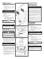 3
3
-
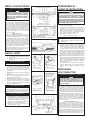 4
4
-
 5
5
-
 6
6
-
 7
7
-
 8
8


Broan 88000 Series Guía de instalación
- Categoría
- Campanas de cocina
- Tipo
- Guía de instalación