Simplicity 01935-0 Manual de usuario
- Categoría
- Accesorios para vehículos de motor
- Tipo
- Manual de usuario

Owner’s Manual / Manual del Propietario
[193174GS Rev 1 (09/02/05)]
Part Number 531 30 00-69
Read this manual carefully and become familiar with your generator.
Know the applications, the limitations and any hazards involved.
Lea este manual de manera cuidadosa y familiarícese con su generador.
Conozca sus usos, sus limitaciones y cualquier peligro relacionado con el mismo.
01935 1365GN

2
TABLE OF CONTENTS
Safety Rules. . . . . . . . . . . . . . . . . . . . . . . . . . . . . . . . . . . . 2-4
Know Your Generator. . . . . . . . . . . . . . . . . . . . . . . . . . . . . 5
Assembly. . . . . . . . . . . . . . . . . . . . . . . . . . . . . . . . . . . . . . 6-7
Operation . . . . . . . . . . . . . . . . . . . . . . . . . . . . . . . . . . . . 8-14
Maintenance . . . . . . . . . . . . . . . . . . . . . . . . . . . . . . . . . . . . 15
Storage . . . . . . . . . . . . . . . . . . . . . . . . . . . . . . . . . . . . . . . . 16
Troubleshooting. . . . . . . . . . . . . . . . . . . . . . . . . . . . . . . . . 17
Schematic/ Wiring Diagram . . . . . . . . . . . . . . . . . . . . . 18-19
Replacement Parts . . . . . . . . . . . . . . . . . . . . . . . . . . . . 20-24
Warranty . . . . . . . . . . . . . . . . . . . . . . . . . . . . . . . . . . . . . . 25
EQUIPMENT
DESCRIPTION
Read this manual carefully and become familiar
with your generator. Know the applications, the
limitations and any hazards involved.
This generator is an engine–driven, revolving field,
alternating current (AC) generator. It was designed to
supply electrical power for operating compatible electrical
lighting, appliances, tools and motor loads.The generator’s
revolving field is driven at about 3,600 rpm by a single-
cylinder engine.
CAUTION! DO NOT exceed the generator’s
wattage/amperage capacity. See “Don’t Overload
Generator”.
Every effort has been made to ensure that information in
this manual is accurate and current. However, we reserve
the right to change, alter or otherwise improve the product
and this document at any time without prior notice.
The Emission Control System for this generator is
warranted for standards set by the Environmental
Protection Agency and the California Air Resources Board.
For warranty information refer to the engine owner’s
manual.
SAFETY RULES
This is the safety alert symbol. It is used to
alert you to potential personal injury hazards.
Obey all safety messages that follow this
symbol to avoid possible injury or death.
The safety alert symbol ( ) is used with a signal word
(DANGER, CAUTION,WARNING), a pictorial and/or a
safety message to alert you to hazards. DANGER indicates
a hazard which, if not avoided, will result in death or
serious injury. WARNING indicates a hazard which, if not
avoided, could result in death or serious injury.
CAUTION indicates a hazard which, if not avoided, might
result in minor or moderate injury. CAUTION, when used
without the alert symbol, indicates a situation that could
result in equipment damage. Follow safety messages to
avoid or reduce the risk of injury or death.
Hazard Symbols and Meanings
Safety Rules
The engine exhaust from this product contains
chemicals known to the State of California to cause
cancer, birth defects, or other reproductive harm.
WARNING
Fire
Explosion
Toxic Fumes
Hot Surface
Electrocution
Kickback
Electrical Shock
Explosive Pressure
Chemical Burn
Copyright © 2005 Briggs & Stratton Power Products
Group, LLC. All rights reserved. No part of this material
may be reproduced or transmitted in any form by any
means without the express written permission of Briggs &
Stratton Power Products Group, LLC.

3
Safety Rules
• DO NOT allow any open flame, spark, heat, or lit cigarette
during and for several minutes after charging a battery.
• Wear protective goggles, rubber apron, and rubber gloves.
Storage batteries give off explosive hydrogen gas
during recharging.
Hydrogen gas stays near battery for a long time
after battery has been charged.
Slightest spark will ignite hydrogen and cause
explosion.
You can be blinded or severely injured.
Battery electrolyte fluid contains acid and is
extremely caustic.
Contact with battery fluid will cause severe
chemical burns.
DANGER
• This generator does not meet U. S. Coast Guard Regulation
33CFR-183 and should not be used on marine applications.
• Failure to use the appropriate U. S. Coast Guard approved
generator could result in death or serious injury and/or
property damage.
WARNING
• When using generator for backup power, notify utility
company. Use approved transfer equipment to isolate
generator from electric utility.
• Use a ground fault circuit interrupter (GFCI) in any damp or
highly conductive area, such as metal decking or steel work.
• DO NOT touch bare wires or receptacles.
• DO NOT use generator with electrical cords which are worn,
frayed, bare or otherwise damaged.
• DO NOT operate generator in the rain or wet weather.
• DO NOT handle generator or electrical cords while standing
in water, while barefoot, or while hands or feet are wet.
• DO NOT allow unqualified persons or children to operate or
service generator.
Generator produces powerful voltage.
Failure to isolate generator from power utility
can result in death or injury to electric utility
workers due to backfeed of electrical energy.
WARNING
• Operate generator ONLY outdoors.
• Keep exhaust gas from entering a confined area through
windows, doors, ventilation intakes or other openings.
• DO NOT operate generator inside any building or enclosure
(even if doors or windows are open), including the generator
compartment of a recreational vehicle (RV).
Running generator gives off carbon monoxide,
an odorless, colorless, poison gas.
Breathing carbon monoxide will cause nausea,
fainting or death.
WARNING
WHEN ADDING OR DRAINING FUEL
• Turn generator OFF and let it cool at least 2 minutes before
removing fuel cap. Loosen cap slowly to relieve pressure in
tank.
• Fill or drain fuel tank outdoors.
• DO NOT overfill tank.Allow space for fuel expansion.
• Keep fuel away from sparks, open flames, pilot lights, heat, and
other ignition sources.
• DO NOT light a cigarette or smoke.
WHEN STARTING EQUIPMENT
• Ensure spark plug, muffler, fuel cap and air cleaner are in place.
• DO NOT crank engine with spark plug removed.
• If fuel spills, wait until it evaporates before starting engine.
WHEN OPERATING EQUIPMENT
• Do not tip engine or equipment at angle which causes fuel to
spill.
• This generator is not for use in mobile equipment or marine
applications.
WHEN TRANSPORTING OR REPAIRING
EQUIPMENT
• Transport/repair with fuel tank EMPTY or with fuel shutoff
valve OFF.
• Disconnect spark plug wire.
WHEN STORING FUEL OR EQUIPMENT WITH FUEL
IN TANK
• Store away from furnaces, stoves, water heaters, clothes
dryers or other appliances that have pilot light or other
ignition source because they can ignite fuel vapors.
Fuel and its vapors are extremely flammable and
explosive.
Fire or explosion can cause severe burns or
death.
WARNING

4
• Use generator only for intended uses.
• If you have questions about intended use, ask your Husqvarna
dealer or contact customer service at 1-877-224-0458.
• Operate generator only on level surfaces.
• DO NOT expose generator to excessive moisture, dust, dirt,
or corrosive vapors.
• DO NOT insert any objects through cooling slots.
• If connected devices overheat, turn them off and disconnect
them from generator.
• Shut off generator if:
-electrical output is lost;
-equipment sparks, smokes, or emits flames;
-unit vibrates excessively.
Improper treatment of generator can damage it and
shorten its life.
CAUTION
Safety Rules
• When starting engine, pull cord slowly until resistance is felt
and then pull rapidly to avoid kickback.
• NEVER start or stop engine with electrical devices plugged in
and turned on.
Rapid retraction of starter cord (kickback) will
pull hand and arm toward engine faster than
you can let go.
Broken bones, fractures, bruises or sprains could
result.
WARNING
WHEN ADJUSTING OR MAKING REPAIRS TO YOUR
GENERATOR
• Disconnect the spark plug wire from the spark plug and place
the wire where it cannot contact spark plug.
WHEN TESTING FOR ENGINE SPARK
• Use approved spark plug tester.
• DO NOT check for spark with spark plug removed.
Unintentional sparking can result in fire or
electric shock.
WARNING
• DO NOT touch hot surfaces and avoid hot exhaust gases.
• Allow equipment to cool before touching.
• The generator must be at least 5 feet from structures having
combustible walls and/or other combustible materials.
• Keep at least 3 feet of clearance on all sides of generator for
adequate cooling, maintenance and servicing.
• Reflective exhaust heat may damage fuel tank causing fire.
• Code of Federal Regulation (CFR) Title 36 Parks, Forests, and
Public Property require equipment powered by an internal
combustion engine to have a spark arrester, maintained in
effective working order, complying to USDA Forest service
standard 5100-1C or later revision. In the State of California a
spark arrester is required under section 4442 of the California
Public resources code. Other states may have similar laws.
Running engines produce heat.Temperature of
muffler and nearby areas can reach or exceed
150°F (65°C).
Severe burns can occur on contact.
Combustible debris, such as leaves, grass, brush,
ect. can catch fire.
WARNING
• DO NOT tamper with governed speed. Generator supplies
correct rated frequency and voltage when running at governed
speed.
• DO NOT modify generator in any way.
Excessively high operating speeds increase risk of injury
and damage to generator.
Excessively low speeds impose a heavy load.
CAUTION
• See “Don’t Overload Generator”.
• Start generator and let engine stabilize before connecting
electrical loads.
• Connect electrical loads in OFF position, then turn ON for
operation.
• Turn electrical loads OFF and disconnect from generator
before stopping generator.
Exceeding generators wattage/amperage capacity can
damage generator and/or electrical devices connected
to it.
CAUTION

5
12 Volt DC,10 Amp Receptacle — Recharge a discharged
12 Volt automotive type battery through this receptacle.
120 Volt AC, 20 Amp GFCI Duplex Receptacles —
May be used to supply electrical power for the operation
of 120 Volt AC, 20 Amp, single phase, 60 Hz electrical,
lighting, appliance, tool and motor loads.
120/240 Volt AC, 30 Amp Locking Receptacle — May
be used to supply electrical power for the operation of
120 and/or 240 Volt AC, 30 Amp, single phase, 60 Hz
electrical, lighting, appliance, tool and motor loads.
Air Cleaner —
Protects engine by filtering dust and debris
out of intake air.
Choke Lever — Used when starting a cold engine.
Circuit Breakers (AC) — Push to reset circuit breakers
are provided to protect the generator against electrical
overload.
Fuel Tank — Capacity of seven (7) U.S. gallons.
Grounding Fastener — Consult your local agency having
jurisdiction for grounding requirements in your area.
Hour Meter — Displays and records how many hours
your generator has run (up to 9,999.9).
Idle Control Switch — The idle control runs the engine at
normal (high) speeds when there is a load present and runs
the engine at idle (low) speeds when a load is not present.
Oil Fill — Add engine oil here.
Recoil Starter — Used to start the engine.
Engine Switch — Set this switch to "On" before using
recoil starter. Set switch to "Off" to switch off engine.
Spark Arrester Muffler — Exhaust muffler lowers
engine noise and is equipped with a spark arrester screen.
KNOW YOUR GENERATOR
Read this owner’s manual and safety rules before operating your generator.
Compare the illustrations with your generator, to familiarize yourself with the locations of various controls and
adjustments. Save this manual for future reference.
120 Volt AC, 20 Amp GFCI
Duplex Receptacles
Fuel Tank
Choke Lever
Recoil Starter
Engine Switch
Circuit
Breakers (AC)
120/240 Volt AC,
30 Amp Receptacle
Spark Arrester Muffler
Air Cleaner
Grounding
Fastener
Oil Fill
Idle Control Switch
Hour Meter
12 Volt DC,10 Amp
Receptacle
Features and Controls

6
ASSEMBLY
Your generator requires some assembly and is ready for
use after it has been properly serviced with the
recommended oil and fuel.
If you have any problems with the assembly of your
generator, please call the generator helpline at
1–877–224–0458. If calling for assistance, please have the
model, revision, and serial number from the data tag available.
Remove Generator From Carton
1. Set the carton on a rigid flat surface.
2. Remove everything from carton except generator.
3. Open carton completely by cutting each corner from
top to bottom.
4. Leave generator on carton to install wheel kit.
Carton Contents
Check all contents. If any parts are missing or damaged, call
the generator helpline at 1–877–224–0458.
• The generator
• Generator and engine owner’s manuals
• Locking 30 Amp plug
• Battery charge cables
• Engine oil
• Wheel kit
Install Wheel Kit
The wheel kit is designed to greatly improve the portability
of your generator.
NOTE: Wheel kit is not intended for over-the-road use.
You will need a socket wrench with 1/2" or 13mm sockets
and a needle-nose pliers to install this kit.
Refer to Figure 1 and install the wheel kit as follows:
1. Place the bottom of the generator frame on a flat, even
surface.Temporarily place unit on blocks to ease assembly.
2. Slide axle through both axle mounting brackets on
cradle frame, as shown in Figure 1.
3. Slide a wheel over the axle.
NOTE: Be sure to install both wheels with the air
pressure valve on the outboard side.
4. Place the e-ring onto the groove in the axle.You may
add the flat washer if desired.
Assembly
Support Leg
Nut
Axle
Flat Washer
Wheel
E-Ring
Figure 1 — Install Wheel Kit
20 mm Cap Screw
Nut
3/4” Cap Screw
Vibration Mount
Use existing hardware
to attach left side of
support leg to unit
Nut
Handle Pin
Handle
Flat Washer
Nylon Washer
45 mm Cap Screw
Nylon Washer

7
5. Place one end of the needle nose pliers on the bottom
of the axle and the other end of the pliers on top of
the e-ring. Seat the e-ring by pressing the pliers closed.
6. Repeat step 3 through 5 to secure second wheel.
7. Remove the temporary blocks.
8. Attach the vibration mounts to the support leg with
3/4” capscrews and lock nuts.
9. To aid support leg assembly, rest generator on cradle,
engine end down. Remove the existing hardware from
the left unit vibration mount with 13mm wrench. Use
the same hardware to attach the support leg.
10. Attach the other side of the support leg with a 20 mm
cap screw and lock nut. Rest generator on wheels and
support leg.
11. Attach handles to handle brackets on generator frame,
as shown in Figure 1, with 45 mm capscrews, flat
washers, nylon washers, and lock nuts.
12. Loop handle pins to generator frame as shown in
Figure 1. Raise handles and insert handle pins to move
generator.
13. Check each fastener to ensure it is secure and the
tires are inflated between 15-40 PSI.
BEFORE STARTING THE
ENGINE
Add Engine Oil
• Place generator on a level surface.
• Refer to engine owner’s manual and follow oil
recommendations and instructions.
NOTE: Check oil often during engine break–in. Refer to
engine owner’s manual for recommendations.
NOTE: The generator assembly rotates on a prelubricated
and sealed ball bearing that requires no additional
lubrication for the life of the bearing.
Add Fuel
NOTE: This gasoline engine is certified to operate on
gasoline. Exhaust Emission Control System: EM (Engine
Modifications).
1. Use clean, fresh, regular UNLEADED gasoline with a
minimum of 85 octane. DO NOT use fuel which
contains Methanol. DO NOT mix oil with fuel.
2. Clean area around fuel fill cap, remove cap.
3. Slowly add regular unleaded fuel to fuel tank. Be careful
not to overfill.Allow about 1.5" of tank space for fuel
expansion (Figure 2).
4. Install fuel cap and wipe up any spilled fuel.
Assembly
CAUTION
• Refer to engine manual for oil fill information.
• Damage to equipment resulting from failure to follow this
instruction will void warranty.
Any attempt to crank or start the engine before it has
been properly filled with the recommended oil will result
in equipment failure.
WHEN ADDING FUEL
• Turn generator OFF and let it cool at least 2 minutes before
removing fuel cap. Loosen cap slowly to relieve pressure in
tank.
• Fill fuel tank outdoors.
• DO NOT overfill tank.Allow space for fuel expansion.
• Keep fuel away from sparks, open flames, pilot lights, heat, and
other ignition sources.
• DO NOT light a cigarette or smoke.
Fuel and its vapors are extremely flammable and
explosive.
Fire or explosion can cause severe burns or
death.
WARNING
Fuel
Tank
1.5” Air Space
Figure 2 - Fuel Expansion

8
USING THE GENERATOR
System Ground
The generator has a system ground that connects the
generator frame components to the ground terminals on
the AC output receptacles.The system ground is connected
to the AC neutral wire (the neutral is bonded to the
generator frame).
Special Requirements
There may be Federal or State Occupational Safety and
Health Administration (OSHA) regulations, local codes, or
ordinances that apply to the intended use of the generator.
Please consult a qualified electrician, electrical inspector, or
the local agency having jurisdiction.
• In some areas, generators are required to be registered
with local utility companies.
• If the generator is used at a construction site, there may
be additional regulations which must be observed.
Connecting to a Building’s Electrical
System
Connections for standby power to a building’s electrical
system must be made by a qualified electrician.The
connection must isolate the generator power from utility
power, and must comply with all applicable laws and
electrical codes.
Generator Location
Generator Clearance
The generator must be at least 5 ft. (152 cm) from
structures having combustible walls and/or other
combustible materials. Leave at least 3 ft. (92 cm) all around
generator including overhead, for adequate cooling,
maintenance and servicing.
Place generator in a well ventilated area, which will allow
for removal of deadly exhaust gas. DO NOT place
generator where exhaust gas could accumulate and enter
inside or be drawn into a potentially occupied building.
Ensure exhaust gas is kept away from any windows, doors,
ventilation intakes or other openings that can allow exhaust
gas to collect in a confined area (Figure 3). Prevailing winds
and air currents should be taken into consideration when
positioning generator.
Operation
Figure 3 — Generator Clearance
Exhaust Port
Typical Generator Shown
• When using generator for backup power, notify utility
company. Use approved transfer equipment to isolate
generator from electric utility.
• Use a ground fault circuit interrupter (GFCI) in any damp or
highly conductive area, such as metal decking or steel work.
• DO NOT touch bare wires or receptacles.
• DO NOT use generator with electrical cords which are worn,
frayed, bare or otherwise damaged.
• DO NOT operate generator in the rain.
• DO NOT handle generator or electrical cords while standing
in water, while barefoot, or while hands or feet are wet.
• DO NOT allow unqualified persons or children to operate or
service generator.
Generator produces powerful voltage.
Failure to isolate generator from power utility
can result in death or injury to electric utility
workers due to backfeed of electrical energy.
WARNING
• Operate generator ONLY outdoors.
• Keep exhaust gas from entering a confined area through
windows, doors, ventilation intakes or other openings.
• DO NOT operate generator inside any building or enclosure
(even if doors or windows are open), including the generator
compartment of a recreational vehicle (RV).
Running generator gives off carbon monoxide,
an odorless, colorless, poison gas.
Breathing carbon monoxide will cause nausea,
fainting or death.
WARNING

9
OPERATING THE
GENERATOR
Starting the Engine
Disconnect all electrical loads from the generator. Use the
following start instruction steps by numerical order:
1. Make sure unit is on a level surface.
IMPORTANT: Failure to start and operate unit on a level
surface will cause the unit not to start or shut down during
operation.
2. Turn fuel valve to “On” position (Figure 4).The fuel
valve handle should be vertical (pointing toward
ground) for fuel to flow.
3. Make sure Idle Control switch is in “Off” position
(Figure 5).
4. Start engine according to instructions given in engine
owner’s manual.
NOTE: If engine starts after 3 pulls but fails to run, or if
unit shuts down during operation, make sure unit is on a
level surface and check for proper oil level in crankcase.
This unit may be equipped with a low oil protection device.
See engine manual.
Connecting Electrical Loads
• Let engine stabilize and warm up for a few minutes after
starting.
• Plug in and turn on the desired 120 and/or 240 Volt AC,
single phase, 60 Hz electrical loads.
• DO NOT connect 240 Volt loads to the 120 Volt duplex
receptacles.
• DO NOT connect 3–phase loads to the generator.
• DO NOT connect 50 Hz loads to the generator.
• DO NOT OVERLOAD THE GENERATOR. See
“Don’t Overload Generator”.
Operation
Fuel Valve is shown
in the “On” position
Figure 4 — Fuel Valve
Figure 5 — Idle Control Switch
• See “Don’t Overload Generator”.
• Start generator and let engine stabilize before connecting
electrical loads.
• Connect electrical loads in OFF position, then turn ON for
operation.
• Turn electrical loads OFF and disconnect from generator
before stopping generator.
Exceeding generator’s wattage/amperage capacity can
damage generator and/or electrical devices connected to it.
CAUTION
• When starting engine, pull cord slowly until resistance is felt
and then pull rapidly to avoid kickback.
• NEVER start or stop engine with electrical devices plugged in
and turned on.
Rapid retraction of starter cord (kickback) will
pull hand and arm toward engine faster than
you can let go.
Broken bones, fractures, bruises or sprains could
result.
WARNING
• DO NOT touch hot surfaces and avoid hot exhaust gases.
• Allow equipment to cool before touching.
• The generator must be at least 5 feet from structures having
combustible walls and/or other combustible materials.
• Keep at least 3 feet of clearance on all sides of generator for
adequate cooling, maintenance and servicing.
• Reflective exhaust heat may damage fuel tank causing fire.
• Code of Federal Regulation (CFR) Title 36 Parks, Forests, and
Public Property require equipment powered by an internal
combustion engine to have a spark arrester, maintained in
effective working order, complying to USDA Forest service
standard 5100-1C or later revision. In the State of California a
spark arrester is required under section 4442 of the California
Public resources code. Other states may have similar laws.
Running engines produce heat.Temperature of
muffler and nearby areas can reach or exceed
150°F (65°C).
Severe burns can occur on contact.
Combustible debris, such as leaves, grass, brush,
ect. can catch fire.
WARNING

10
Stopping the Engine
1. Unplug ALL electrical loads from generator panel
receptacles. NEVER start or stop engine with electrical
devices plugged in and turned ON.
2. Move idle control switch to “Off” position.
3. Let engine run at no-load for several minutes to
stabilize internal temperatures of engine and generator.
4. Turn engine off according to instructions given in the
engine owner’s manual.
5. Move fuel valve to “Off” position.
Operating Automatic Idle Control
This switch is designed to greatly improve fuel economy.
When this switch is turned ON, the engine will only
run at its normal high governed engine speed when an
electrical load is connected.When an electrical load is
removed, the engine will run at a reduced speed. With the
switch off, the engine will run at the normal high engine
speed. Always have the switch off when starting and
stopping the engine.
Charging a Battery
Your generator has the capability of recharging a discharged
12 Volt automotive or utility style storage battery. DO
NOT use the unit to charge any 6 Volt batteries. DO NOT
use the unit to crank an engine having a discharged battery.
To recharge 12 Volt batteries, proceed as follows:
1. Check fluid level in all battery cells. If necessary, add
ONLY distilled water to cover separators in battery
cells. DO NOT use tap water.
2. If battery is equipped with vent caps, make sure they
are installed and are tight.
3. If necessary, clean battery terminals.
4. Connect battery charge cable connector plug to panel
receptacle identified by the words “12-VOLTS D.C.”.
5. Connect battery charge cable clamp with red handle
to the positive (+) battery terminal (Figure 6).
6. Connect battery charge cable clamp with black handle
to the negative (–) battery terminal (Figure 6).
7. Start engine. Let engine run while battery recharges.
8. When battery has charged, shut down engine
NOTE: Use an automotive hydrometer to test battery state
of charge and condition. Follow the hydrometer
manufacturer’s instructions carefully. Generally, a battery is
considered to be at 100% state of charge when specific gravity
of its fluid (as measured by hydrometer) is 1.260 or higher.
COLD WEATHER
OPERATION
Under certain weather conditions (temperatures below
40°F [4°C] combined with high humidity), your generator
may experience icing of the carburetor and/or the
crankcase breather system.To reduce this problem, you
need to perform the following:
1. Make sure generator has clean, fresh fuel.
2. Open fuel valve (turn valve to open position).
3. Use SAE 5W-30 oil (synthetic preferred, see engine
manual).
4. Check oil level daily or after every eight (8) hours of
operation.
5. Maintain generator following “Maintenance Schedule”
in engine manual.
6. Shelter unit from elements.
Operation
Figure 6 — Battery Connections
• DO NOT allow any open flame, spark, heat, or lit cigarette
during and for several minutes after charging a battery.
• Wear protective goggles, rubber apron, and rubber gloves.
Storage batteries give off explosive hydrogen gas
during recharging.
Hydrogen gas stays near battery for a long time
after battery has been charged.
Slightest spark will ignite hydrogen and cause
explosion.
You can be blinded or severely injured.
Battery electrolyte fluid contains acid and is
extremely caustic.
Contact with battery fluid will cause severe
chemical burns.
DANGER

11
In an emergency, use the original shipping carton as a
temporary shelter:
7. Cut off all carton flaps.
8. Cut out one long side of carton to expose muffler side
of unit as shown in Figure 7.
IMPORTANT: The generator must be at least 5 ft. (1.5 m)
from structures having combustible walls and/or other
combustible materials. Leave at least 3 ft. (1 m) all around
generator including overhead, for adequate cooling,
maintenance and servicing.
9. Cut appropriate slots to access receptacles of unit.
10. Start unit, then place carton over it.
NOTE: Remove shelter when temperatures are above
40°F [4°C].
For a more permanent shelter, build a structure that will
enclose three sides and the top of the generator.
7. Make sure entire muffler-side of generator is exposed,
as shown in Figure 7.
IMPORTANT: The generator must be at least 5 ft. (1.5 m)
from structures having combustible walls and/or other
combustible materials. Leave at least 3 ft. (1 m) all around
generator including overhead, for adequate cooling,
maintenance and servicing.
8. Face exposed end away from wind and elements.
9. Structure should hold enough heat created by the
generator to prevent icing problem.
10. Start and run engine outdoors.
11. Keep exhaust gas from entering a confined area
through windows, doors, ventilation intakes or other
openings.
12. DO NOT enclose generator any more than shown in
Figure 7.
13. Remove shelter when temperatures are above 40°F
[4°C].
14. Turn engine OFF and let cool two (2) minutes before
refueling.
Operation
Figure 7 — Permanent Cold Weather Shelter
Wind
• DO NOT touch hot surfaces and avoid hot exhaust gases.
• Allow equipment to cool before touching.
• The generator must be at least 5 feet from structures having
combustible walls and/or other combustible materials.
• Keep at least 3 feet of clearance on all sides of generator for
adequate cooling, maintenance and servicing.
• Reflective exhaust heat may damage fuel tank causing fire.
• Remove shelter when temperatures are above 40°F [4°C].
Running engines produce heat.Temperature of
muffler and nearby areas can reach or exceed
150°F (65°C).
Severe burns can occur on contact.
Combustible debris, such as leaves, grass, brush,
etc. can catch fire.
WARNING
• Operate generator ONLY outdoors.
• Keep exhaust gas from entering a confined area through
windows, doors, ventilation intakes or other openings.
• DO NOT operate generator inside any building or enclosure
(even if doors or windows are open), including the generator
compartment of a recreational vehicle (RV).
Running generator gives off carbon monoxide,
an odorless, colorless, poison gas.
Breathing carbon monoxide can cause nausea,
fainting or death.
WARNING

12
RECEPTACLES
120/240 Volt AC, 30 Amp, Locking
Receptacle
Use a NEMA L14–30 plug with this receptacle. Connect a
4–wire cord set rated for 250 Volt AC loads at 30 Amps (or
greater) (Figure 8).You can use the same 4–wire cord if you
plan to run a 120 Volt load.
This receptacle powers 120/240 Volt AC, 60 Hz, single
phase loads requiring up to 6,500 watts of power (6.5 kW)
at 27.1 Amps for 120 Volts or 240 Volts.The outlet is
protected by a push–to–reset circuit breaker.
120 Volt AC, 20 Amp, GFCI Duplex
Receptacles
Each duplex receptacle (Figure 9) is protected against
overload by a push–to–reset circuit breaker.
Use each receptacle to operate 120 Volt AC, single–phase,
60 Hz electrical loads requiring up to 2,400 watts (2.4 kW)
at 20 Amps of current. Use cord sets that are rated for
125 Volt AC loads at 20 Amps (or greater).
12 Volt DC, 10 Amp Receptacle
This receptacle (Figure 10) allows you to recharge a 12 Volt
automotive or utility style storage battery with the battery
charge cables provided.
This receptacle can not recharge 6 Volt batteries and can
not be used to crank an engine having a discharged battery.
See “Charging a Battery” on page 10 before attempting to
recharge a battery.This outlet is protected by a 10 Amp
self-resetting circuit breaker.
Operation
Figure 8 — 120/240 Volt AC, 30 Amp Receptacle
4-Wire Cord Set
240V
120V
120V
W (Neutral)
X (Hot)
Y (Hot)
NEMA L14-30
Ground (Green)
Figure 9 — 120 Volt, 20 Amp GFCI Duplex Receptacle
Figure 10 — 12 Volt DC, 10 Amp Receptacle
• NEVER attempt to power a device requiring more amperage
than generator or receptacle can supply.
• DO NOT overload the generator. See “Don’t Overload
Generator”.
Receptacles may be marked with rating value greater
than generator output capacity.
CAUTION

13
Ground Fault Protection
This unit is equipped with a Ground Fault Circuit
Interrupter (GFCI).This device meets applicable federal,
state and local codes.
The GFCI protects against electrical shock that may be
caused if your body becomes a path which electricity
travels to reach the ground.This could happen if you touch
a “Live” appliance or wire, or are touching plumbing or
other materials that connect to the ground.
When protected by a GFCI, one may still feel a shock, but
the GFCI should cut current off quickly enough so that a
person in normal health should not suffer any serious
electrical injury.
Testing the GFCI
Test your GFCI outlet every month and before use, as
follows:
• Push the black “Test” button.The red “Reset” button
should pop out, which should allow no power to reach
the outlet. Use a test lamp in each outlet to test this.
• If the GFCI tests good, restore power by pressing the
“Reset” button firmly until it is fully in place and locks in
that position. If the GFCI outlet does not reset
properly, do not use the outlet. Call a local service
center.
• If the GFCI trips by itself at any time, reset and test the
outlet. If the reset button does pop out when the
test button is pressed, do not use the outlet. Call
a local service center.
Operation
• The GFCI will not protect you against the following situations:
-Line-to-line shocks;
-Current overloads or line-to-line short circuits.
• The fuse or circuit breaker at the control panel must provide
such protection.
Generator produces powerful voltage.
WARNING
• DO NOT use any outlets on the circuit.
• Call a qualified electrician.
The “Reset” button does not pop out or the test lamp
remains lit when the “Reset” button is popped out.
CAUTION

14
DON'T OVERLOAD
GENERATOR
Capacity
You must make sure your generator can supply enough
rated (running) and surge (starting) watts for the items you
will power at the same time. Follow these simple steps:
1. Select the items you will power at the same time.
2. Total the rated (running) watts of these items.This is
the amount of power your generator must produce to
keep your items running. See Figure 11.
3. Estimate how many surge (starting) watts you will
need. Surge wattage is the short burst of power
needed to start electric motor-driven tools or
appliances such as a circular saw or refrigerator.
Because not all motors start at the same time, total
surge watts can be estimated by adding only the
item(s) with the highest additional surge watts to the
total rated watts from step 2.
Example:
Total Rated (Running) Watts = 3075
Highest Additional Surge Watts = 1800
Total Generator Output Required = 4875
Power Management
To prolong the life of your generator and attached devices,
it is important to take care when adding electrical loads to
your generator.There should be nothing connected to the
generator outlets before starting it's engine.The correct
and safe way to manage generator power is to sequentially
add loads as follows:
1. With nothing connected to the generator, start the
engine as described in this manual.
2. Plug in and turn on the first load, preferably the largest
load you have.
3. Permit the generator output to stabilize (engine runs
smoothly and attached device operates properly).
4. Plug in and turn on the next load.
5. Again, permit the generator to stabilize.
6. Repeat steps 4 and 5 for each additional load.
NEVER add more loads than the generator capacity.Take
special care to consider surge loads in generator capacity,
as described above.
*Wattages listed are approximate only. Check tool or
appliance for actual wattage.
Tool or Appliance
Rated (Running)
Watts
Additional Surge
(Starting) Watts
Window Air
Conditioner
1200 1800
Refrigerator 800 1600
Deep Freezer 500 500
Television 500 -
Light (75 Watts) 75 -
3075 Total
Running Watts
1800 Highest
Surge Watts
Tool or Appliance
Rated*
(Running)
Watts
Additional
Surge
(Starting)
Watts
Essentials
Light Bulb - 75 watt 75 -
Deep Freezer 500 500
Sump Pump 800 1200
Refrigerator/Freezer - 18 Cu. Ft. 800 1600
Water Well Pump - 1/3 HP 1000 2000
Heating/Cooling
Window AC - 10,000 BTU 1200 1800
Window Fan 300 600
Furnace Fan Blower - 1/2 HP 800 1300
Kitchen
Microwave Oven - 1000 Watt 1000 -
Coffee Maker 1500 -
Electric Stove - Single Element 1500 -
Hot Plate 2500 -
Family Room
DVD/CD Player 100 -
VCR 100 -
Stereo Receiver 450 -
Color Television - 27” 500 -
Personal Computer w/17” monitor 800 -
Other
Security System 180 -
AM/FM Clock Radio 300 -
Garage Door Opener - 1/2 HP 480 520
Electric Water Heater - 40 Gallon 4000 -
DIY/Job Site
Quartz Halogen Work Light 1000 -
Airless Sprayer - 1/3 HP 600 1200
Reciprocating Saw 960 960
Electric Drill - 1/2 HP 1000 1000
Circular Saw - 7 1/4” 1500 1500
Miter Saw - 10” 1800 1800
Table Planer - 6” 1800 1800
Table Saw/Radial Arm Saw - 10” 2000 2000
Air Compressor - 1-1/2 HP 2500 2500
Figure 11 - Wattage Reference Chart
Operation

15
SPECIFICATIONS
Starting Wattage . . . . . . . . . . . . . . . . . . . . . . .8,125 watts
Wattage . . . . . . . . . . . . . . . . . . . . . . . . . . . . .6,500 watts
AC Load Current:
At 120 Volts . . . . . . . . . . . . . . . . . . . . . . . . .54.2 Amps
At 240 Volts . . . . . . . . . . . . . . . . . . . . . . . . .27.1 Amps
Phase . . . . . . . . . . . . . . . . . . . . . . . . . . . . . . . . . .1–phase
Rated Frequency . . . . . . . . . . . . . . . . . . . . . . . . .60 Hertz
Fuel Tank Capacity . . . . . . . . . . . . . . . . . . . . 7 U.S. gallons
Shipping Weight . . . . . . . . . . . . . . . . . . . . . . . . . . 205 lbs.
GENERAL MAINTENANCE
RECOMMENDATIONS
The Owner/Operator is responsible for making sure that
all periodic maintenance tasks are completed on a timely
basis; that all discrepancies are corrected; and that the unit
is kept clean and properly stored. NEVER operate a
damaged or defective generator.
NOTE: Should you have questions about replacing
components on your Husqvarna generator, please call
1-877-224-0458 for assistance.
Engine Maintenance
See engine owner’s manual for instructions.
KEEP OUT OF REACH OF CHILDREN. DON'T
POLLUTE. CONSERVE RESOURCES. RETURN
USED OIL TO COLLECTION CENTERS.
Generator Maintenance
Generator maintenance consists of keeping the unit clean
and dry. Operate and store the unit in a clean dry
environment where it will not be exposed to excessive
dust, dirt, moisture or any corrosive vapors. Cooling air
slots in the generator must not become clogged with dirt,
leaves or any other foreign material.
NOTE: DO NOT use a garden hose to clean generator.
Water can enter engine fuel system and cause problems. In
addition, if water enters generator through cooling air slots,
some of the water will be retained in voids and cracks of
the rotor and stator winding insulation.Water and dirt
buildup on the generator internal windings will eventually
decrease the insulation resistance of these windings.
Generator Cleaning
• Use a damp cloth to wipe exterior surfaces clean.
• Use a soft bristle brush to loosen caked on dirt or oil.
• Use a vacuum cleaner to pick up loose dirt and debris.
• Use low pressure air (not to exceed 25 psi) to blow
away dirt. Inspect cooling air slots and opening on
generator.These openings must be kept clean and
unobstructed.
• Used motor oil has been shown to cause skin cancer in
certain laboratory animals.
• Thoroughly wash exposed areas with soap and water.
Avoid prolonged or repeated skin contact with used
motor oil.
CAUTION
• DO NOT expose generator to excessive moisture, dust, dirt,
or corrosive vapors.
• DO NOT insert any objects through cooling slots.
Improper treatment of generator can damage it and
shorten its life.
CAUTION
Maintenance
WHEN ADJUSTING OR MAKING REPAIRS TO YOUR
GENERATOR
• Disconnect the spark plug wire from the spark plug and place
the wire where it cannot contact spark plug.
WHEN TESTING FOR ENGINE SPARK
• Use approved spark plug tester.
• DO NOT check for spark with spark plug removed.
Unintentional sparking can result in fire or
electric shock.
WARNING

16
STORAGE
The generator should be started at least once every seven
days and allowed to run at least 30 minutes. If this cannot
be done and you must store the unit for more than
30 days, use the following guidelines to prepare it for
storage.
Generator Storage
• Clean the generator as outlined in “Generator Cleaning”.
• Check that cooling air slots and openings on generator
are open and unobstructed.
Engine Storage
See engine owner’s manual for instructions.
Other Storage Tips
• To prevent gum from forming in fuel system or on
essential carburetor parts, add fuel stabilizer into fuel
tank and fill with fresh fuel. Run the unit for several
minutes to circulate the additive through the carburetor.
The unit and fuel can then be stored for up to
24 months. Fuel stabilizer can be purchased locally.
• DO NOT store fuel from one season to another unless
it has been treated as described above.
• Replace fuel container if it starts to rust. Rust and/or dirt
in fuel can cause problems if it's used with this unit.
• Store unit in a clean and dry area.
Storage
• DO NOT place a storage cover over a hot generator.
• Let equipment cool for a sufficient time before placing the
cover on the equipment.
Storage covers can be flammable.
WARNING

17
TROUBLESHOOTING
Troubleshooting
Problem Cause Correction
No AC output is available, but
generator is running.
1. One of the circuit breakers is
open.
2. Fault in generator.
3. Poor connection or defective cord
set.
4. Connected device is bad.
1. Reset circuit breaker.
2. Contact Authorized service facility.
3. Check and repair.
4. Connect another device that is in
good condition.
Generator runs good at no-load
but "bogs" down" when loads are
connected.
1. Short circuit in a connected load.
2. Generator is overloaded.
3. Shorted generator circuit.
1. Disconnect shorted electrical load.
2. See "Don't Overload Generator".
3. Contact Authorized service facility.
Generator will not start; or starts
and runs rough.
Low oil level. Fill crankcase to proper level or place
generator on level surface.
Generator shuts down during
operation.
1. Out of gasoline.
2. Low oil level.
1. Fill fuel tank.
2. Fill crankcase to proper level or
place generator on level surface.
Generator lacks power. Load is too high. See "Don't Overload Generator".

18
SCHEMATIC
Schematic

19
WIRING DIAGRAM
Wiring Diagram

20
EXPLODED VIEW – MAIN UNIT
Exploded Views

21
PARTS LIST – MAIN UNIT
Item Part # Description
1 N192958GS KIT, Cradle (Includes Items 20, 31
& 55)
2 194218GS KIT,Vibration Mount
3 N92531GS SUPPORT, Engine
4 190220GS HOUSING, Engine Adapter
5 194151GS KIT, Hardware Mounting Adapter
6 NSP ASSY,Alternator (see page 22)
7 N92731GS SUPPORT, Eng/Muffler
8 96796GS WASHER, M8 Flat
9 194219GS KIT,Vibration Mount
10 190274BGS SBHCS, 3/8-16 x 1.0 Lg.
11 187365JGS HHCS, 5/16-24 x 7.75
12 195078GS KIT, Engine Mounting Hardware
14 195079GS KIT, Muffler Bracket w/ Hardware
15 NSP GASKET, Muffler
16 31579GS SPACER, 3/8 x 3/4 x 3/8
17 192569GS MUFFLER
18 67989GS NUT, Flange Serrated
19 83083GS SCREEN, Spark Arrest
20 B4986GS DECAL, Ground
21 194153GS KIT,Vibration Mount
22 86494GS SCREW,Wing, M6 - 1.0 x 16
23 86292GS SCREW, 10 - 16 x 3/4, Self Drill
24 194390GS SHIELD, Heat
25 191190GS CAP
26 74908GS TAPTITE, M5-0.8 x 10
27 B2153GS SCREW, 12-14 x 7/8, Self Drill
28 * WASHER, Shakeproof Ext. #10
31 196830GS DECAL, Hot Muffler
33 193157GS HARNESS,Wire, Power
Item Part # Description
34 195422GS COVER, Bearing Carrier w/ Cap
37 192376GS SCREW, 12-24 x 1/2 Thd Forming
38 56893GS SCREW, 10-24 x 1/2 Crimptite
40 195076GS KIT, Fuel Tank Hardware
41 192980GS KIT,Valve Fuel Tank
44 193500GS ASSY,Tank, Fuel (Includes Items 41,
50, 51 & 52)
45 B4363GS CAP, Fuel Gauge
48 195373GS WIRE, Ground
50 188333GS DECAL, Instruction, Fuel Level
51 194799GS DECAL, Danger
52 189235GS DECAL, Start Instructions
54 194448GS KIT, Insulation with Clip
55 197798GS DECAL, Fuel Shut-off
58 193049GS ASSY, Control Panel (see page 23)
60 194389GS SHIELD, Heat
900 § ENGINE
Parts Not Illustrated
43438GS PLUG, 250V 30A, 4 Prong
BB3061BGS OIL, Bottle
65787GS CABLE, Battery Charge
B1464GS MANUAL, Engine
193174GS MANUAL, Owners
195077GS KIT, Decals, Srv
* - Items without part numbers are common fasteners and
are available at your local hardware store.
§ - Contact Engine Manufacturer
Exploded Views

22
Exploded Views
EXPLODED VIEW AND PARTS LIST – ALTERNATOR
Item Part # Description
1 186059GS ADAPTER, Mounting,Alternator
2 192919GS ROTOR (Includes Item 11)
3 192920AGS STATOR
4 193336GS RBC, (with O-Ring, p/n 189197GS)
5 86308HGS HHCS, M6 - 1.0 x 140 SEMS
6 66386GS ASSY, Holder, Brush
7 66849GS TAPTITE, M5 - 0.8 x 16
8 22694GS RECEPTACLE, 6 pin
9 81917GS PIN, Roll, 4mm x 10
10 193428AGS ASSY,Wire, Ground
11 65791GS BEARING
13 192403XGS ASSY,Wire, Ground
14 189769GS REGULATOR,Voltage,AVR
15 65795GS RECTIFIER
16 66849AGS TAPTITE, M5 - 0.8 x 20

23
EXPLODED VIEW AND PARTS LIST – CONTROL PANEL
Item Part # Description
1 B191714GS PANEL, Control
2 B192836GS BOX, Control Panel
3 23897GS WASHER, Flat, #10 - M5
4 49226GS WASHER, Lock, M5
5 91526GS PPHMS, M5 - 0.8 x 12
6 22447GS WASHER, M6 - 1/4, Int. Shakeproof
7 82538GS SWITCH, Rocker
8 90418GS OUTLET, 12VDC, Snap
9 77604GS METER, Hour
10 43182GS WASHER, Lock, M3
11 51714GS NUT, M3 - 0.5
12 43181GS PHMS, M3 - 0.5 x 10
13 22694GS HOUSING, Receptacle
14 87962GS BREAKER, Circuit, 12V, 10A
15 84028GS TRANSFORMER, Idle Cnt
16 64525GS STANDOFF, Hex
Item Part # Description
17 189367GS PCB, Idle Control
18 64526GS PHTS, #6-32 x 3/8
19 193077GS STRIP,Terminal
20 22264GS WASHER, Lock, M4
21 75477GS PPHMS, M5 - 0.8 x 20
22 51715GS NUT, M4 - 0.7
23 43180GS WASHER, Flat, M4
24 75207GS BREAKER, Circuit, 20A, with
Hardware
25 23365GS WASHER, Shakeproof, Int. #8
26 75207PGS BREAKER, Circuit, 25A, with
Hardware
27 193095GS JUMPER,Terminal Block
28 43437GS OUTLET, 120/240V, 30A
29 80409GS OUTLET, 120V, 20A, Duplex. GFCI
30 189502GS HARNESS,Wire
Exploded Views

24
Exploded Views
EXPLODED VIEW AND PARTS LIST – WHEEL KIT
Item Part # Description
1 * WASHER,Wheel
2 B4966GS WHEEL
3 191267KGS AXLE, 5/8" x 24.80"
4 191265GS E-RING
5 * HHCS, M8 - 1.25 x 20 Lg.
6 B89595GS BRACKET, Support, Unit
7 87841GS MOUNT,Vibe Donut Type
8 * HHCS, 1/4 - 20 x 3/4 Lg.
9 67989GS NUT, M8 Flange Serrated
10 194005GS NUT, 1/4 - 20 Flange Nylok
11 189718GS GRIP, Handle
12 B193200GS ASSY, Handle (Includes Item 11)
13 * HHCS, M8 - 1.25 x 45Lg
14 * WASHER, Flat, 5/16 - M8
15 * NUT, M8 Nylok
16 * WASHER, Nylon
17 B4135GS PIN, with Lanyard
* - Items without part numbers are common fasteners and are
available at your local hardware store.

WARRANTY PERIOD*
* The warranty period begins on the date of purchase by the first retail consumer or commercial end user, and continues for
the period of time stated in the table above. "Consumer use" means personal residential household use by a retail consumer.
"Commercial use" means all other uses, including use for commercial, income producing or rental purposes. Once equipment
has experienced commercial use, it shall thereafter be considered as commercial use for purposes of this warranty.
** The engine and starting batteries are warranted solely by the manufacturers of those products.
WARRANTY REGISTRATION IS NOT NECESSARY TO OBTAIN WARRANTY ON BRIGGS & STRATTON
POWER PRODUCTS EQUIPMENT. SAVE YOUR PROOF OF PURCHASE RECEIPT. IF YOU DO NOT PROVIDE
PROOF OF THE INITIAL PURCHASE DATE AT THE TIME WARRANTY SERVICE IS REQUESTED,THE
MANUFACTURING DATE OF THE EQUIPMENT WILL BE USED TO DETERMINE THE WARRANTY PERIOD.
About your equipment warranty:
We welcome warranty repair and apologize to you for being inconvenienced.Any Authorized Service Dealer may perform
warranty repairs. Most warranty repairs are handled routinely, but sometimes requests for warranty service may not be
appropriate. For example, warranty service would not apply if equipment damage occurred because of misuse, lack of routine
maintenance, shipping, handling, warehousing or improper installation. Similarly, the warranty is void if the manufacturing date
or the serial number on the equipment has been removed or the equipment has been altered or modified. During the
warranty period, the Authorized service dealer, at its option, will repair or replace any part that, upon examination, is found to
be defective under normal use and service.This warranty will not cover following repairs and equipment:
• Normal Wear: Outdoor power equipment, like all mechanical devices, needs periodic parts, service and replacement to
perform well.This warranty does not cover repair when normal use has exhausted the life of a part or the equipment.
• Installation and Maintenance: This warranty does not apply to equipment or parts that have been subjected to
improper or unauthorized installation or alteration and modification, misuse, negligence, accident, overloading,
overspeeding, improper maintenance, repair or storage so as, in our judgment, to adversely affect its performance and
reliability.This warranty also does not cover normal maintenance such as adjustments, fuel system cleaning and
obstruction (due to chemical, dirt, carbon or lime, etc.).
• Other Exclusions: This warranty excludes wear items such as quick couplers, oil gauges, belts, o-rings, filters, pump
packing, etc., pumps which have been run without water supplied or damage or malfunctions resulting from accidents,
abuse, modifications, alterations, or improper servicing or freezing or chemical deterioration.Accessory parts such as
guns, hoses, wands and nozzles are excluded from the product warranty.Also excluded is used, reconditioned, and
demonstration equipment; equipment used for prime power in place of utility power and equipment used in life
support applications.
BRIGGS & STRATTON POWER PRODUCTS GROUP, LLC
JEFFERSON,WISCONSIN, U.S.A.
LIMITED WARRANTY
“Briggs & Stratton Power Products will repair or replace, free of charge, any part or parts of this Husqvarna® branded
product** that are defective in material or workmanship or both.Transportation charges on parts submitted for repair
or replacement under this warranty must be borne by purchaser.This warranty is effective for the time periods and
subject to the conditions stated below. For warranty service, find the nearest Authorized Service Dealer by calling
1-877-224-0458.Warranty service may only be performed by a Briggs & Stratton Power Products Authorized service
dealer.
THERE IS NO OTHER EXPRESS WARRANTY. IMPLIED WARRANTIES, INCLUDING THOSE OF MERCHANTABILITY
AND FITNESS FOR A PARTICULAR PURPOSE,ARE LIMITED TO THE TIME PERIOD SPECIFIED, OR TO THE EXTENT
PERMITTED BY LAW.ANY AND ALL IMPLIED WARRANTIES ARE EXCLUDED. LIABILITY FOR INCIDENTAL OR
CONSEQUENTIAL DAMAGES UNDER ANY AND ALL WARRANTIES ARE EXCLUDED TO THE EXTENT
EXCLUSION IS PERMITTED BY LAW. Some countries or states do not allow limitations on how long an implied
warranty lasts, and some countries or states do not allow the exclusion or limitation of incidental or consequential
damages, so the above limitation and exclusion may not apply to you.This warranty gives you specific legal rights and you
may also have other rights which vary from country to country or state to state.”
Equipment ** Consumer Use Commercial Use
Pressure Washer 2 Years 2 Years
Portable Generator 2 Years (2nd year parts only) 2 Years (2nd year parts only)

26
TABLA DE CONTENIDOS
Reglas De Seguridad . . . . . . . . . . . . . . . . . . . . . . . . . . . . . . . . 26-28
Conozca Su Generador . . . . . . . . . . . . . . . . . . . . . . . . . . . . . . . . 29
Montaje . . . . . . . . . . . . . . . . . . . . . . . . . . . . . . . . . . . . . . . . . . 30-31
Operación . . . . . . . . . . . . . . . . . . . . . . . . . . . . . . . . . . . . . . . . 32-38
Especificaciones . . . . . . . . . . . . . . . . . . . . . . . . . . . . . . . . . . . . . . 39
Mantenimiento . . . . . . . . . . . . . . . . . . . . . . . . . . . . . . . . . . . . . . . 39
Almacenamiento. . . . . . . . . . . . . . . . . . . . . . . . . . . . . . . . . . . . . . 40
Diagnosticos De Averías. . . . . . . . . . . . . . . . . . . . . . . . . . . . . . . . 41
Notas. . . . . . . . . . . . . . . . . . . . . . . . . . . . . . . . . . . . . . . . . . . . 42-43
Garantia . . . . . . . . . . . . . . . . . . . . . . . . . . . . . . . . . . . . . . . . . . . . 44
DESCRIPCIÓN DEL EQUIPO
Lea este manual de manera cuidadosa y
familiarícese con su generador. Conozca sus usos,
sus limitaciones y cualquier peligro relacionado
con el mismo.
Este generador funciona en base a un motor, de campo eléctrico
giratorio y de corriente alterna (AC). Fue diseñado con la
finalidad de proveer energía eléctrica para luces eléctricas,
aparatos, herramientas compatibles y cargas de motor. El campo
giratorio del generador funciona a una velocidad de 3,6000 rpm
usando un motor con un uno cilindro.
¡PRECAUCIÓN! NO sobrepase la capacidad de vataje y amperaje
del generador. Revise "No Sobrecargue Generador".
Se ha hecho cada esfuerzo posible para asegurarse que la
información que aparece en este manual es exacta y se encuentra
actualizada. Sin embargo, nosotros se reserva el derecho a
cambiar, alterar o de otra manera mejorar, el producto y este
documento en cualquier momento, sin previo aviso.
El Sistema de Control de Emisiones para este generador está
garantizado para juegos estándares por la Agencia de Protección
Ambiental y el Consejo de recursos de aire de California. Para
mayor información acerca de la garantía, consulte con el manual
del propietario del motor.
REGLAS DE SEGURIDAD
Éste es el símbolo de alerta de seguridad. Sirve
para advertir al usuario de un posible riesgo para
su integridad física. Siga todos los mensajes de
seguridad que figuren después de este símbolo
para evitar lesiones o incluso la muerte.
El símbolo de alerta de seguridad ( ) es usado con una palabra
(PELIGRO,ADVERTENCIA, PRECAUCIÓN), un mensaje por
escrito o una ilustración, para alertarlo acerca de cualquier
situación de peligro que pueda existir. PELIGRO indica un riesgo
el cual, si no se evita, causará la muerte o una herida grave.
ADVERTENCIA indica un riesgo el cual, si no se evita, puede
causar la muerte o una herida grave. PRECAUCIÓN indica un
riesgo, el cual, si no se evita, puede causar heridas menores o
moderadas. PRECAUCIÓN, cuando se usa sin el símbolo de
alerta, indica una situación que podría resultar en el daño del
equipo. Siga los mensajes de seguridad para evitar o reducir los
riesgos de heridas e inclusive la muerte.
Símbolos de Peligro y Significados
El escape del motor de este producto contiene
elementos químicos reconocidos en el Estado de
California por producir cáncer, defectos de nacimiento u
otros daños de tipo reproductivo.
ADVERTENCIA
Reglas de Seguridad
Fuego
Explosión
Gases Tóxicos
Superficie Caliente
Retroceso
Electrocutamiento
Descarga Eléctrica
Presión Explosiva
Quemaduras Química

27
Reglas de Seguridad
• NO permita ninguna llama abierta, chispa, calor, o encienda un
cigarrillo durante y por varios minutos después de haber recargado la
batería.
• Lleve puestos las gafas protectoras, delantal y guantes de goma.
Las baterías almacenadas producen hidrógeno
explosivo mientras estén siendo recargadas.
El hidrógeno puede permanecer cerca de la batería
por un periodo largo de tiempo, después que la
batería haya sido recargada.
Una pequeña chispa puede encender el hidrógeno y
causar una explosión.
Usted puede quedar ciego o sufrir heridas muy graves.
El fluido de electrolito de la batería contiene ácido y
es extremadamente cáustico.
El contacto con el fluido de la batería puede causar
quemaduras químicas severas.
PELIGRO
• Este generador no cumple la norma 33CFR-183 del cuerpo de
guardacostas de EE.UU. y no debe utilizarse en aplicaciones marinas.
• El uso de un generador no homologado por cuerpo de guardacostas
de EE.UU. puede provocar lesiones y daños materiales.
ADVERTENCIA
• Cuando use un generador como poder de energía auxiliar, notifique a
la compañía de utilidades. Use el equipo de transferencia aprobado
para aislar el generador de otra utilidad eléctrica.
• Use un interruptor para la falla del circuito de tierra (GFCI) en
cualquier área bastante húmeda o que sea altamente conductiva, tales
como terrazas de metal o trabajo hecho con acero.
• NO toque los alambres pelados o receptáculos.
• NO use un generador con cables eléctricos que estén malgastados,
rotos, pelados o dañados de cualquier forma.
• NO opere el generador bajo la lluvia.
• NO maneje el generador o cables eléctricos mientras esté parado en
agua, descalzo o cuando las manos y los pies estén mojados.
• NO permita que personas descalificadas o niños operen o sirvan al
generador.
Los generadores producen un voltaje muy poderoso.
Si no aísla el generador de utilidades de energía,
puede hacer que los trabajadores de electricidad
sufran heridas graves e inclusive la muerte, debido a
la retroalimentación de la energía eléctrica.
ADVERTENCIA
• Opere el generador SOLAMENTE al aire libre.
• Asegúrese de que los gases de escape no puedan entrar por ventanas,
puertas, tomas de aire de ventilación u otras aberturas en un espacio
cerrado en el que puedan acumularse.
• NO opere el generador dentro de un edificio o lugar cerrado (aunque
haya puertas o ventanas abiertas), incluyendo el compartimiento del
generador en un vehículo recreativo o RV.
Al generador funcionar, se produce monóxido de
carbono, un gas inodoro y venenoso.
El respirar el monóxido de carbono, producirá
náusea, desmayo o la muerte.
ADVERTENCIA
CUANDO AÑADA COMBUSTIBLE O VACÍE EL
DEPÓSITO
• Apague el generador (posición OFF) y déjelo enfriar al menos por
2 minutos antes de remover la tapa de la combustible.Afloje la tapa
lentamente para dejar que la presión salga del tanque.
• Llene o vacíe el depósito de combustible a la intemperie.
• NO llene demasiado el tanque. Permita al menos espacio para la
expansión del combustible.
• Mantenga la combustible alejada de chispas, llamas abiertas, pilotos,
calor y otras fuentes de ignición.
• NO encienda un cigarrillo o fume.
CUANDO PONGA EN FUNCIONAMIENTO EL
EQUIPO
• Compruebe que la bujía, el silenciador, el tapón del depósito de
combustible y el filtro de aire están instalados.
• NO arranque el motor sin la bujía instalada.
• Si se ha derramado combustible, espere a que se evapore antes de
arrancar el motor.
CUANDO OPERE EL EQUIPO
• NO incline el motor o el equipo, de tal manera que la combustible se
pueda derramar.
• Este generador no es apto para el uso en equipos móviles ni en
aplicaciones marinas.
CUANDO TRANSPORTE O REPARE EL EQUIPO
• Transporte o repare el equipo con el tanque de combustible vacío, o
con la válvula para apagar el combustible, apagada (posición OFF).
• Desconecte el cable de la bujía.
CUANDO ALMACENE O GUARDE EL EQUIPO CON
COMBUSTIBLE EN EL TANQUE
• Almacene alejado de calderas, estufas, calentadores de agua, secadoras
de ropa u otros aparatos electrodomésticos que posean pilotos u
otras fuentes de ignición, porque ellos pueden encender los vapores
de la combustible.
La combustible y sus vapores son extremadamente
inflamables y explosivos.
El fuego o una explosión pueden causar quemaduras
severas e inclusive la muerte.
ADVERTENCIA

28
Reglas de Seguridad
• Use el generador solamente con la finalidad para el cual fue diseñado.
• Si usted tiene alguna pregunta acerca de las finalidades de uso del
generador, pregúntele a su concesionario a Husqvarna o contacte en
1-877-224-0458.
• Opere el generador solamente en superficies niveladas.
• NO exponga al generador a una humedad excesiva, polvo, suciedad o
vapores corrosivos.
• NO inserte cualquier objeto a través de las ranuras de enfriamiento.
• Si los aparatos conectados se sobrecalientan, apáguelos y
desconéctelos del generador.
• Apague el generador si:
-Se pierde la salida eléctrica;
-El equipo produce chispas, humo o emite llamas;
-La unidad vibra de una manera excesiva.
El tratamiento inadecuado del generador puede dañarlo y
acortar su vida productiva.
PRECAUCIÓN
• Cuando arranque el motor, tire lentamente del cable hasta sentir una
resistencia y, a continuación, tire rápidamente de él para evitar su
retroceso.
• NUNCA arranque o pare el motor cuando haya aparatos eléctricos
conectados y en funcionamiento.
El rápido repliegue del cable del arrancador
(retroceso) impedirá que el usuario suelte el cable a
tiempo y tirará de su mano y brazo hacia el motor.
Como resultado, podrían producirse fracturas,
contusiones o esguinces.
ADVERTENCIA
CUANDO AJUSTE O HAGA REPARACIONES A SU
GENERADOR
• Siempre desconecte el alambre de la bujía y colóquelo donde no
pueda entrar en contacto con la bujía.
CUANDO PRUEBE LA BUJÍA DEL MOTOR
• Utilice un comprobador de bujías homologado.
• NO comprueba la chispa sin la bujía instalada.
Chispear involuntario puede tener como resultado el
fuego o el golpe eléctrico.
ADVERTENCIA
• NO toque las superficies calientes y evite los gases del escape a alta
temperatura.
• Permita que el equipo se enfríe antes de tocarlo.
• El generador debe estar situado a un mínimo de 152 cm (5 pies) de toda
estructura con muros combustibles y/o otras materias combustibles.
• Mantenga un mínimo de 92 cm (3 pies) alrededor de la carcasa del
generador, para facilitar la ventilación y el mantenimiento del generador.
• El calor que refleja el escape podría dañar el depósito de combustible
y provocar un incendio.
• El Código de Normativa Federal (CFR,Título 36: Parques, Bosques y
Propiedad Pública) obliga a instalar una pantalla apagachispas en los
equipos con motor de combustión interno y a mantenerla en buenas
condiciones de funcionamiento, conforme a la norma 5100-1C (o
posterior) del Servicio Forestal de la USDA. En el Estado de
California, la ley exige el uso de una pantalla apagachispas (Sección
4442 del Código de Recursos Públicos de California). En otros
estados puede haber leyes similares en vigor.
Los motores al funcionar producen calor. La
temperatura del silenciador y de las áreas cercanas
puede alcanzar o pasar los 150ºF (65ºC).
Quemaduras severas pueden ocurrir al hacer
contacto.
Los residuos como hojas, hierba, maleza, etc. se
pueden inflamar.
ADVERTENCIA
• NO cambie ninguna velocidad determinada. El generador suministra
una frecuencia y un voltaje calificado cuando funciona a una velocidad
determinada.
• NO modifique al generador en ninguna forma.
Las velocidades de operación en exceso, aumentan los
riesgos de heridas y daños al generador.
Las velocidades bajan en exceso, imponen una carga muy pesada.
PRECAUCIÓN
• Vea "No sobrecargue generador".
• Encienda su generador y deje que el motor se estabilice antes de
conectar las cargas eléctricas.
• Conecte las cargas eléctricas en la posición de apagado (OFF), luego
encienda (ON) para su operación.
• Apague (OFF) las cargas eléctricas y desconéctelas del generador
antes de parar el generador.
El sobrepasar la capacidad del amperaje y vataje del
generador, puede dañar al generador y los aparatos eléctricos
conectados al mismo.
PRECAUCIÓN

29
CONOZCA SU GENERADOR
LEA ESTE MANUAL DEL PROPIETARIO Y LAS REGLAS DE SEGURIDAD ANTES DE OPERAR SU GENERADOR.
Compare las ilustraciones con su Generador para familiarizarse con las ubicaciones de los diferentes controles y ajustes.
Conserve este manual para referencias futuras.
Aceite llena — Agrega motor aceite aquí.
Conector de Tierra – Consulte con el organismo responsable
de la normativa vigente de conexión a tierra.
Cortacircuitos (AC) — Cada tomacorriente posee un
cortacircuito para proteger el generador contra sobrecargas
eléctricas. Los cortacircuitos son del tipo “oprimir para reposicionar”.
Culatazo el Principio — Usó para comenzar motor.
Depurador de Aire — Filtra el aire de entrada a medida que
penetra en el motor.
Interruptor del Control de Marcha en Vacío – El control de
marcha en vacío hace funcionar el motor a velocidades normales
(altas) cuando existe una carga presente y hace funcionar el motor
a velocidades de marcha en vacío (bajas) cuando no existen cargas
presentes. Esta característica mejora el ahorro de combustible,
prolonga la vida del motor y disminuye el ruido del motor.
Interruptor del Motor — Deberá estar en la posición “On”
(En) para darle arranque al motor. Colóquelo en la posición “Off”
(Apagado) para detener un motor en funcionamiento.
Contador de la Hora – Muestra y registra las horas que ha
funcionado su generador (hasta 9,999.9).
Palanca del Cebador — Usada cuando se está dando arranque
a un motor frío.
Silenciador Apagachispas — El silenciador disminuye el ruido
del motor y está equipado con una pantalla apagachispas.
Tanque del Combustible — El tanque tiene una capacidad de
7 galones americanos de gasolina sin contenido de plomo.
Tomacorrientes de 12 Voltios DC – Este tomacorriente le
permite recargar baterías tipo servicio o automotriz de 12 Voltios
o batería de almacenamiento tipo servicio utilizando los cables
para cargar baterías.
Tomacorriente GFCI Dobles de 120 Voltios AC, 20 Amp
— Pueden ser utilizados para suministrar alimentación eléctrica
para el funcionamiento de cargas del motor, herramientas,
aparatos especiales e iluminación eléctrica de 120 Voltios AC a
20 Amperios, monofásica de 60 Hz.
Tomacorriente con Dispositivo de Seguridad de
120/240 Voltios, 30 Amp — Puede ser utilizado para suministrar
alimentación eléctrica para el funcionamiento de cargas del motor,
herramientas, aparatos especiales e iluminación eléctrica de
120 y/o 240 Voltios AC a 30 Amperios, monofásica de 60 Hz.
Tomacorrientes GFCI Doble
de 120 Voltios AC, 20 Amp
Tanque de Combustible
Palanca del Cebador
Culatazo el Principio
Interruptor del Motor
Cortacircuitos (AC)
Tomacorrientes con Dispositivo de
Seguridad de 120/240 Voltios AC, 30 Amp
Silenciador Apagachispas
Depurador de Aire
Conector de Tierra
Aceite llena
Interruptor del Control
de Marcha en Vacío
Contador de la Hora
Tomacorrientes de
12 Voltios DC
Características y Controles

30
MONTAJE
Su generador requiere de ciertos procedimientos de montaje y
solo estará listo para ser utilizado después de haberle
suministrado servicio con el combustible y aceite recomendados.
Si usted tiene problemas con el montaje de su generador,
por favor llame a la línea de ayuda para generadores al
1-877-224-0458. Si llamar para la ayuda, tiene por favor el
modelo, la revisión y el número de serie de etiqueta de datos
disponible.
Para Retirar el Generador de la Caja
1. Coloque la caja de cartón en una superficie rígida y plana.
2. Saque todo el contenido de la caja de cartón, a excepción
del generador.
3. Abra completamente la caja de cartón cortando cada una de
sus esquinas de arriba abajo.
4. Mantenga el generador sobre el cartón para instalar el juego
de ruedas.
Contenido De La Caja
Revise todo el contenido. Si alguna de las partes no está presente
o está dañada, por favor llame a la linea de ayuda para
generadores al 1-877-224-0458.
• La unidad principal
• Manual del propietario y motor
• Aceite para motor
• Cables para cargar baterías
• Tapones de fijación
• Juego de ruedas
Instale el Juego de Ruedas
El juego de ruedas está diseñado para mejorar el transporte del
generador.
NOTA: Este Juego de Ruedas no ha sido diseñado para ser usado
en la carretera.
Necesitará una llave de cubos con cubos de 1/2”” o 13mm y unas
pinsas de punta para instalar el juego de ruedas.
Consulte la Figura 12 y instale el juego de ruedas como
se describe a continuación:
1. Coloque el fondo de la camilla del generador en una
superficie plana.Temporalmente, coloque la unidad en
bloques para ensamblarla fácilmente.
2. Deslice el eje a través de ambos soportes de montaje, en el
marco de la camilla, como se muestra en la Figura 12.
3. Deslice una rueda en el eje.
NOTA: Asegúrese de instalar ambas ruedas con la válvula de aire
hacia el lado de afuera.
4. Coloque el e-ring en la ranura del eje.
Montaje
Figura 12 — Instale el Juego de Ruedas
Alfilere de Asa
Asa
Arandelas
Arandelas de Nylon
45 mmTornillos
Arandelas de Nylon
Use hardware existente
para conectar el lado
izquierdo de pierna de
apoyo a la unidad
Pierna de Apoyo
Tuercas
Eje
Arandela
Rueda
E-Ring
20 mmTornillos
Tuercas
3/4” Tornillos
Montajes Antivibratorios
Tuercas

31
Montaje
5. Coloque un extremo de las pinzas de puntas de aguja en la
parte inferior del eje y el otro extremo de las pinzas en la
parte superior del e-ring.Asiente el e-ring cerrando las pinzas.
6. Repita los pasos 3 por 5 para asegurar la segunda rueda.
7. Remueva los bloques temporales.
8. Instale los montajes antivibratorios a la pata de soporte
utilizando dos tornillos prisioneros 3/4” tuercas de seguridad.
9. Para ayudar al ensamblaje de la pata de apoyo, haga descansar
el generador en la camilla, con la parte del motor hacia abajo.
Quite el hardware existente del monte izquierdo de la
vibración de la unidad con 13mm llave inglesa. Use el mismo
hardware para conectar la pierna de apoyo.
10. Conecte el otro lado de la pierna de apoyo con un 20 mm
tornillo de la tapa y nuez de cerradura. Descanse el
generador en la pierna de ruedas y apoyo.
11. Fije el asas para manejar paréntesis en el marco del
generador, como se muestra en la Figura 12. Para ello utilice
un 45 mm tornillos, arandelas, arandelas de nylon y una
tuercas.
12. Serpentee alfileres de asa al marco del generador como
mostrado en la Figura 12. Suba el asa e inserte su pasador
para mover el generador.
13. Verifique que todas las piezas estén apretadas y las llantas
estén infladas con aire entre 15-40 PSI.
ANTES DE DARLE ARRANQUE AL
MOTOR
Agregar Aceite al Motor
• Coloque la generador sobre una superficie nivelada.
• Consulte el manual del propietario del motor para añadir al
motor el aceite recomendado.
NOTA: Verifique el aceite del motor de manera
frecuente cuando éste se esfuerce demasiado. Consulte el
manual del propietario del motor para conocer cuáles
son las recomendaciones al respecto.
NOTA: El campo giratorio del generador se encuentra en un
cojinete pre-lubricado y sellado que no requiere lubricación
adicional por la vida útil del cojinete.
Agregue Combustible
NOTA: Este motor está certificado para funcionar con gasolina.
Sistema de control de emisiones de gases de escape: EM
(Modificaciones del motor).
1. Utilice combustible normal sin plomo, limpia y nueva con un
mínimo de 85 octanos. NO utilice combustible que contenga
metanol ni mezcle aceite con combustible.
2. Limpie el área alrededor de la tapa de llenado del
combustible, retire la tapa.
3. Agregue lentamente combustible regular "SIN PLOMO" al
tanque de combustible. Use un embudo para evitar que se
derrame. Llene el tanque lentamente hasta aproximadamente
1.5" por debajo de la parte la cima del cuello del tubo de
llenado (Figura 13).
4. Instale la tapa del tanque de combustible y limpie la
combustible que se haya derramado.
PRECAUCIÓN
• Consulte el manual del propietario del motor para añadir al motor
el aceite recomendado.
• El daño a la lavadora a presión, resultado de la desatención a
esta precaución, no será cubierto por la garantía.
Cualquier intento para arancar el motor antes de haberle
proporcionado el mantenimiento apropiado con el aceite
recomendado, podría ocasionar la falla del motor.
Combustible
Tanque
Espacio de 1.5"
Figura 13 - Espacio de Combustible
CUANDO AÑADA COMBUSTIBLE
• Apague el generador (posición OFF) y déjelo enfriar al menos por
2 minutos antes de remover la tapa de la combustible.Afloje la tapa
lentamente para dejar que la presión salga del tanque.
• Llene el depósito de combustible a la intemperie.
• NO llene demasiado el tanque. Permita al menos espacio para la
expansión del combustible.
• Mantenga la combustible alejada de chispas, llamas abiertas, pilotos,
calor y otras fuentes de ignición.
• NO encienda un cigarrillo o fume.
La combustible y sus vapores son extremadamente
inflamables y explosivos.
El fuego o una explosión pueden causar quemaduras
severas e inclusive la muerte.
ADVERTENCIA

32
Operación
USO DEL GENERADOR
Tierra del Sistema
El generador dispone de una conexión a tierra del sistema que
conecta los componentes del bastidor a los terminales de tierra
de los enchufes hembra de salida de CA. La tierra del sistema
está conectada al cable de CA neutro que, a su vez, está
conectado al bastidor del generador (vea “Descripión del
Equipo”).
Requisitos Especiales
Es posible que haya normas u ordenanzas locales y nacionales en
materia de seguridad e higiene en el trabajo aplicables al uso del
generador. Consulte con un electricista cualificado, un inspector
eléctrico o el organismo competente.
• En algunas zonas, es obligatorio registrar los generadores en
las compañías eléctricas locales.
• Si el generador se utiliza en una obra, puede ser necesario
cumplir normas y requisitos adicionales.
Conexión al Sistema Eléctrico de un
Edificio
Las conexiones a efectos de alimentación de reserva al sistema
eléctrico de un edificio deben ser realizadas por un electricista
cualificado. La conexión debe aislar la alimentación del generador
de la alimentación de la red pública y debe cumplir todas las leyes
y normas eléctricas vigentes.
Ubicación del Generador
Espacio Libre Alrededor del Generador
El generador debe estar situado a un mínimo de 152 cm (5 pies)
de toda estructura con muros combustibles y/o otras materias
combustibles. Mantenga un mínimo de 92 cm (3 pies) alrededor
del generador, incluido la parte superior, para facilitar la
ventilación y el mantenimiento del generador.
Sitúe el generador en una zona bien ventilada que permita la
eliminación de los gases de escape mortales. No instale el
generador en lugares en los que los gases de escape se puedan
acumular o entrar en un edificio que pueda estar ocupado.
Asegúrese de que los gases de escape no puedan entrar por
ventanas, puertas, tomas de aire de ventilación u otras aberturas
en un espacio cerrado en el que puedan acumularse (Figura 14).
Tenga en cuenta los vientos y las corriente de aire
preponderantes cuando elija la ubicación del generador.
Figura 14 — Espacio Libre Alrededor del Generador
Salida del Escape
Típica Generador Mostrada
• Cuando use un generador como poder de energía auxiliar, notifique a
la compañía de utilidades. Use el equipo de transferencia aprobado
para aislar el generador de otra utilidad eléctrica.
• Use un interruptor para la falla del circuito de tierra (GFCI) en
cualquier área bastante húmeda o que sea altamente conductiva, tales
como terrazas de metal o trabajo hecho con acero.
• NO toque los alambres pelados o receptáculos.
• NO use un generador con cables eléctricos que estén malgastados,
rotos, pelados o dañados de cualquier forma.
• NO opere el generador bajo la lluvia.
• NO maneje el generador o cables eléctricos mientras esté parado en
agua, descalzo o cuando las manos y los pies estén mojados.
• NO permita que personas descalificadas o niños operen o sirvan al
generador.
Los generadores producen un voltaje muy poderoso.
Si no aísla el generador de utilidades de energía,
puede hacer que los trabajadores de electricidad
sufran heridas graves e inclusive la muerte, debido a
la retroalimentación de la energía eléctrica.
ADVERTENCIA
• Opere el generador SOLAMENTE al aire libre.
• Asegúrese de que los gases de escape no puedan entrar por ventanas,
puertas, tomas de aire de ventilación u otras aberturas en un espacio
cerrado en el que puedan acumularse.
• NO opere el generador dentro de un edificio o lugar cerrado (aunque
haya puertas o ventanas abiertas), incluyendo el compartimiento del
generador en un vehículo recreativo o RV.
Al generador funcionar, se produce monóxido de
carbono, un gas inodoro y venenoso.
El respirar el monóxido de carbono, producirá
náusea, desmayo o la muerte.
ADVERTENCIA

33
OPERANDO EL GENERADOR
Encienda el Motor
Desconecte todas las cargas eléctricas del generador. Use las
siguientes instrucciones para encender, paso por paso, en orden
numérico.
1. Asegúrese de que la unidad está en una superficie plana.
IMPORTANTE: Si la unidad no se arranca y utiliza en una
superficie plana, se pueden producir problemas de arranque y de
parada durante el funcionamiento.
2. Gire la válvula del combustible a la posición "On" (Figura 15).
El asidero de la válvula del combustible debe ser vertical
(señalar hacia el suelo) para el combustible para fluir.
3. Verifique si el interruptor de control secundario se
encuentra “Off” (Apagado) (Figura 16).
4. Ponga en marcha el motor tal y como se explica en el manual
del propietario del motor.
NOTA: Si el motor arranca después de tirar tres veces del
arrancador pero no sigue funcionando, o si la unidad se para en
funcionamiento, asegúrese de que la unidad está en una superficie
plana y compruebe que el nivel de aceite del cigüeñal es correcto.
La unidad puede equiparse con un dispositivo de protección de
bajo nivel de aceite.Vea manual del motor.
Conexion De Cargas Electricas
• Deje que el motor se estabilice y se caliente por unos
minutos después del arranque.
• Conecte y encienda las cargas eléctricas de 120 y/o
240 Voltios AC monofásicas de 60 Hz que desse.
• NO conecte cargas de 240 Voltios a tomacorrientes de
120 Voltios.
• NO conecte cargas trifásicas al generador.
• NO conecte cargas de 50 Hz al generador.
• NO SOBRECARGUE EL GENERADOR.Vea "No
Sobrecargue Generador".
Operación
Válvula del Combustible
en posición “On”
Figura 15 — Válvula de Combustible
• Vea "No sobrecargue generador".
• Encienda su generador y deje que el motor se estabilice antes de
conectar las cargas eléctricas.
• Conecte las cargas eléctricas en la posición de apagado (OFF), luego
encienda (ON) para su operación.
• Apague (OFF) las cargas eléctricas y desconéctelas del generador
antes de parar el generador.
El sobrepasar la capacidad del amperaje y vataje del generador,
puede dañar al generador y los aparatos eléctricos conectados
al mismo.
PRECAUCIÓN
Figura 16 — Interruptor del Control de Marcha en Vacío
• Cuando arranque el motor, tire lentamente del cable hasta sentir una
resistencia y, a continuación, tire rápidamente de él para evitar su
retroceso.
• NUNCA arranque o pare el motor cuando haya aparatos eléctricos
conectados y en funcionamiento.
El rápido repliegue del cable del arrancador
(retroceso) impedirá que el usuario suelte el cable a
tiempo y tirará de su mano y brazo hacia el motor.
Como resultado, podrían producirse fracturas,
contusiones o esguinces.
ADVERTENCIA
• NO toque las superficies calientes y evite los gases del escape a alta
temperatura.
• Permita que el equipo se enfríe antes de tocarlo.
• El generador debe estar situado a un mínimo de 152 cm (5 pies) de toda
estructura con muros combustibles y/o otras materias combustibles.
• Mantenga un mínimo de 92 cm (3 pies) alrededor de la carcasa del
generador, para facilitar la ventilación y el mantenimiento del generador.
• El calor que refleja el escape podría dañar el depósito de combustible
y provocar un incendio.
• El Código de Normativa Federal (CFR,Título 36: Parques, Bosques y
Propiedad Pública) obliga a instalar una pantalla apagachispas en los
equipos con motor de combustión interno y a mantenerla en buenas
condiciones de funcionamiento, conforme a la norma 5100-1C (o
posterior) del Servicio Forestal de la USDA. En el Estado de
California, la ley exige el uso de una pantalla apagachispas (Sección
4442 del Código de Recursos Públicos de California). En otros
estados puede haber leyes similares en vigor.
Los motores al funcionar producen calor. La
temperatura del silenciador y de las áreas cercanas
puede alcanzar o pasar los 150ºF (65ºC).
Quemaduras severas pueden ocurrir al hacer
contacto.
Los residuos como hojas, hierba, maleza, etc. se
pueden inflamar.
ADVERTENCIA

34
Operación
Parado Del Motor
1. Desconecte todas las cargas eléctricas de los tomaco-
rrientes del panel del generador. NUNCA de arranque o
detenga el motor con todos los dispositivos eléctricos
conectados y encendidos.
2. Verifique si el interruptor de control secundario se
encuentra “Off” (Apagado).
3. Deje que el motor funcione sin cargas por algunos minutos
para estabilizar las temperaturas internas del motor y el
generador.
4. Pour éteindre le moteur, suivez les instructions qui figurent
dans le manuel d'utilisation.
5. Cierre la válvula del combustible.
FUNCIONAMIENTO DEL
CONTROL AUTOMATICO DE
MARCHA EN VACIO
Este interruptor ha sido diseñado para mejorar el consumo de
combustible. Cuando éste interruptor sea “Activado”, el motor
funcionará únicamente en su alta velocidad de mando normal una
vez sea conectada una carga eléctrica. Cuando la carga eléctrica es
retirada, el motor funcionará a una velocidad menor. Si el
interruptor está “Desactivado”, el motor funcionará en alta
velocidad normal. Siempre tenga el interruptor en la posición
“Off” (apagado) cuando arranque y detenga el motor.
PROCEDIMIENTO DE CARGA DE
LA BATERIA
Su generador tiene la capacidad de recargar baterías descargadas
de acumuladores tipo servicio o automotriz de 12 Voltios. NO
utilice la unidad para cargar baterías de 6 Voltios. NO use la unidad
para mover motores que tengan la batería descargada.
Para recargar baterías de 12 Voltios, lleve a cabo los
siguientes procedimientos:
• Revise el nivel del líquido en todas las celdas de la batería. Si
es necesario, añada agua destilada UNICAMENTE hasta
cubrir los separadores de las celdas de la batería. NO use
agua de grifo.
• Si la batería está equipada con tapas de desfogue, asegúrese
de que están instaladas y apretadas.
• Limpie los terminales de la batería si es necesario.
• Conecte el enchufe conector del cable de carga de la batería
al tomacorrientes del panel identificado con las palabras
“12-VOLTS D.C.” (“12-VOLTIOS D.C.”).
• Conecte el sujetador del cable de carga de la batería que
tiene la manija roja al terminal positivo (+) de la batería
(Figura 17).
• Conecte el sujetador del cable de carga de la batería que
tiene la manija negra al terminal negativo (-) de la batería
(Figura 17).
• Arranque el motor. Deje que el motor funcione mientras la
batería se recarga.
• Apague el motor cuando la batería se haya cargado.
NOTA: Use un hidrómetro para automóviles para probar el
estado de carga y condición de la batería. Siga cuidadosamente las
instrucciones del fabricante del hidrómetro. Por lo general, se
considera que una batería está en un estado de carga del 100%
cuando la gravedad específica de su líquido (medido por el
hidrómetro) es de 1.260 o mayor.
OPERACIÓN DURANTE UN
CLIMA FRÍO
En ciertas condiciones climáticas (temperaturas inferiores a 4º C
[40º F] combinadas con un alto nivel de humedad), su generador
puede experimentar formación de hielo en el carburador o el
sistema de ventilación del cárter. Para reducir este problema, es
necesario realizar lo siguiente:
1. Asegúrese de que el generador tenga combustible nuevo y
limpio.
2. Abra la válvula de combustible (gire la válvula a la posición
de abierto).
TOMACORRIENTE DE
12 VOLTIOS DC
+ POSITIVO
- NEGATIVO
BATERIA DE 12 VOLTIOS
• NO permita ninguna llama abierta, chispa, calor, o encienda un cigarrillo
durante y por varios minutos después de haber recargado la batería.
• Lleve puestos las gafas protectoras, delantal y guantes de goma.
Las baterías almacenadas producen hidrógeno
explosivo mientras estén siendo recargadas.
El hidrógeno puede permanecer cerca de la batería
por un periodo largo de tiempo, después que la
batería haya sido recargada.
Una pequeña chispa puede encender el hidrógeno y
causar una explosión.
Usted puede quedar ciego o sufrir heridas muy graves.
El fluido de electrolito de la batería contiene ácido y
es extremadamente cáustico.
El contacto con el fluido de la batería puede causar
quemaduras químicas severas.
PELIGRO
Figura 17 — Battery Connections

35
3. Utilice aceite 5W-30 SAE (se prefiere sintético, vea manual
de motor).
4. Verifique el nivel de aceite diariamente o después de cada
ocho (8) horas de funcionamiento.
5. Mantenga el generador que sigue el “Horario de la
Conservación” en el manual de motor.
6. Proteja la unidad de la intemperie.
En caso de emergencia, utilice la caja de cartón del embalaje
original como una protección temporal.
7. Corte las tapas de la caja.
8. Corte uno de los lados largos de la caja para dejar expuesto
el lado del silenciador de la unidad como se muestra en la
Figura 18.
IMPORTANTE: El generador debe estar situado a un mínimo
de 1.5 m (5 pies) de toda estructura con muros combustibles y/o
otras materias combustibles. Mantenga un mínimo de 1 m (3 pies)
alrededor del generador, incluido la parte superior, para facilitar la
ventilación y el mantenimiento del generador.
9. Corte las ranuras adecuadas para tener acceso a los
tomacorrientes de la unidad.
10. Arranque la unidad y después coloque la caja de cartón
encima.
NOTA: Retire la protección cuando la temperatura sea superior
a 4º C [40º F].
Para una protección más permanente, construya una estructura
que rodee los tres lados y la parte superior del generador.
7. Asegúrese de que quede expuesto el lado completo del
silenciador del generador, como se muestra en la Figura 18.
IMPORTANTE: El generador debe estar situado a un mínimo
de 1.5 m (5 pies) de toda estructura con muros combustibles y/o
otras materias combustibles. Mantenga un mínimo de 1 m (3 pies)
alrededor del generador, incluido la parte superior, para facilitar la
ventilación y el mantenimiento del generador.
8. El extremo expuesto debe estar situado en dirección
contraria al viento y los elementos.
9. La estructura deberá conservar suficiente calor del
generador a fin de evitar problemas de formación de hielo.
10. Arranque el motor y manténgalo en marcha en exteriores.
11. Asegúrese de que los gases de escape no puedan entrar por
ventanas, puertas, tomas de aire de ventilación u otras
aberturas en un espacio cerrado en el que puedan
acumularse.
12. El generador no debe quedar más encerrado de lo que se
muestra en la Figura 18.
13. Retire la protección cuando la temperatura sea superior a
4º C [40º F].
14. Apague el motor y déjelo enfriar durante dos (2) minutos
antes de volver a abastecer de combustible.
Operación
Figura 18 — Refugio Frío Permanente del Tiempo
Viento
• NO toque las superficies calientes y evite los gases del escape a alta
temperatura.
• Permita que el equipo se enfríe antes de tocarlo.
• El generador debe estar situado a un mínimo de 1.5 m (5 pies) de
toda estructura con muros combustibles y/o otras materias
combustibles.
• Mantenga un mínimo de 1 m (3 pies) alrededor de la carcasa del
generador, para facilitar la ventilación y el mantenimiento del generador.
• El calor que refleja el escape podría dañar el depósito de combustible
y provocar un incendio.
• Retire la protección cuando la temperatura sea superior a 4º C [40º F].
Los motores al funcionar producen calor. La
temperatura del silenciador y de las áreas cercanas
puede alcanzar o pasar los 150ºF (65ºC).
Quemaduras severas pueden ocurrir al hacer
contacto.
Los residuos como hojas, hierba, maleza, etc. se
pueden inflamar.
ADVERTENCIA
• Opere el generador SOLAMENTE al aire libre.
• Asegúrese de que los gases de escape no puedan entrar por ventanas,
puertas, tomas de aire de ventilación u otras aberturas en un espacio
cerrado en el que puedan acumularse.
• NO opere el generador dentro de un edificio o lugar cerrado (aunque
haya puertas o ventanas abiertas), incluyendo el compartimiento del
generador en un vehículo recreativo o RV.
Al generador funcionar, se produce monóxido de
carbono, un gas inodoro y venenoso.
El respirar el monóxido de carbono, producirá
náusea, desmayo o la muerte.
ADVERTENCIA

36
Operación
RECEPTÁCULOS
120/240 Voltios AC, 30 Amp, Receptáculo
de Seguridad
Use un tapón NEMA L14-30 con este receptáculo. Conecte un
juego de cable de 4 alambres, clasificado como 250 Voltios AC a
30 Amps (o mayor) (Figura 19). Usted puede usar el mismo cable
de 4-alambres si planea trabajar con una carga de 120 Voltios.
Este receptáculo le provee poder a cargas de 120/240 Voltios AC,
de 60 Hz, fase sencilla, que requieren hasta 6,500 vatios de energía
(6.5 kW) a 27.1 Amps, para 120 Voltios o 240 Voltios. La salida
está protegida por un corto-circuito de, del tipo "empuje para
reposicionar".
120 Volt AC, 20 Amp, GFCI Receptáculos
Dobles
Cada receptáculo (Figura 20) está protegido en contra de sobrecargas
por un corto-circuitos de, del tipo "empuje para reposicionar".
Use cada receptáculo para operar 120 Voltios AC, de fase sencilla,
de cargas de 60Hz que requieren hasta 2,400 vatios (2.4 kW) a
corrientes de 20 Amps. Use los juegos de cables que son
calificados para cargas de 125 Voltios AC, a 20 Amps (o mayores).
Receptáculo de 12 Voltios DC
Este receptáculo (Figura 21) le permite recargar una batería de
almacenamiento tipo servicio o automotriz de 12 Voltios
utilizando los cables suministrados para cargar baterías.
Este receptáculo no puede recargar baterías de 6 Voltios y no se
puede usar para darle arranque a motores que tengan la batería
descargada.Vea las seccione “Procedimiento de Carga de la
Batería” (página 33) antes de intentar recargar la batería.
• NUNCA intente suministrar corriente a un dispositivo de amperaje
superior al que puede suministrar el generador o el enchufe hembra.
• NO sobrecargue el generador. Consulte el apartado “No Sobrecargue
Generador”.
El valor nominal que se indica en los enchufes hembra puede
ser superior a la capacidad de salida del generador.
PRECAUCIÓN
Figura 19 — 120/240 Volt AC, 30 Amp, Receptáculo de
Seguridad
Juego de Cable de 4 Alambres
240V
120V
120V
W (Neutro)
X (Cargado)
Y (Cargado)
NEMA L14-30
Tierra (Verde)
Figura 20 — 120 Volt AC, 20 Amp GFCI Receptáculo Doble
Figura 21 — 12 Volt DC, 10 Amp Receptáculo

37
Operación
Protección en Contra de Fallas Eléctricas
Esta unidad se encuentra equipada con un Interruptor del
Circuito en Caso de Fallas Eléctricas (GFCI). Este aparato cumple
con los códigos federales, estatales y locales respectivos.
El GFCI protege en contra de descargas eléctricas que puedan ser
originadas si su cuerpo llega a ser parte conductiva de la
electricidad al hacer tierra. Esto puede pasar si usted toca un
aparato o cable "vivo", o está tocando una plomería u otro tipo
de material que esté conectado a la tierra.
Cuando el GFCI lo proteja, es posible que la persona sienta una
descarga eléctrica, pero el GFCI debería cortar la corriente
rápidamente, de tal manera que la persona que se encuentra en
buena salud, no sufra ningún accidente eléctrico serio.
Sometiendo a Prueba el GFCI
Cada mes, someta a prueba el tomacorriente de su GFCI, de la
manera siguiente:
• Presione el botón negro "Test" (de prueba). El botón rojo
"Reset" (de reposición) debería saltar, lo cual evitará que
ningún tipo de energía llegue al tomacorriente. Use una
lámpara de prueba en cada tomacorriente para examinarlo.
• Si el GFCI pasa la prueba y funciona debidamente, conecte la
energía de nuevo, presionando el botón rojo "Reset"
firmemente, hasta que quede en su lugar adecuado y esté
asegurado en su posición. Si el tomacorriente del GFCI
no vuelve a su lugar original, no use el tomacorriente.
Acuda a un centro local de servicio.
• Si el GFCI salta por sí solo en cualquier momento, póngalo en
la posición original y examine el tomacorriente. Si el botón
rojo "Reset" salta cuando el botón "Test" ha sido
presionado, no use el tomacorriente.Acuda a un
centro local de servicio.
• NO utilice ningún enchufe en el circuito.
• Acuda a un electricista cualificado.
El botón "Reset" (Rearme) no salta o el piloto de prueba
permanece encendido cuando el botón "Reset" salta.
PRECAUCIÓN
• El GFCI no protege contra las siguientes situaciones:
-Descargas de línea a línea;
-Sobrecargas de corriente o cortocircuitos de línea a línea.
• El fusible o el disyuntor del panel de control debe proporcionar este
tipo de protección.
El generador produce una tensión muy elevada.
ADVERTENCIA

38
NO SOBRECARGUE GENERADOR
Capacidad
Usted debe asegurarse que su generador puede proveer el
suficiente vataje calificado (cuando esté funcionando) y de carga
(al encender) para los aparatos a los cuales va a proveer la
energía, al mismo tiempo. Siga estos pasos:
1. Seleccione los aparatos que recibirán la energía, al mismo
tiempo.
2. Totalice los vatios calificados (cuando esté funcionando) de
estos aparatos. Esta es la cantidad de energía que su
generador debe producir para mantener eso aparatos
funcionando adecuadamente.Vea la Figura 22.
3. Calcule la cantidad de vatios de carga (al encender) que
usted necesitará. El vataje de carga es la cantidad mínima de
electricidad, necesaria para encender herramientas o
aparatos con motores eléctricos, tales como, sierras
circulares o refrigeradores. Debido a que no todos los
motores se encienden al mismo momento, el vataje total de
carga se puede estimar al añadir solamente el(los) aparato(s)
con el vataje adicional más alto, al total del vataje calificado,
obtenido en el paso 2.
Ejemplo:
Vataje Total Calificado (cuando esté funcionando)= 3075
Vataje de Carga Adicional más alto = 1800
Salida Total Requerida del Generador = 4875
Control de la Energía
Para prolongar la vida de su generador y los aparatos que estén
conectados al mismo, es muy importante cuidarlo cuando se le
añaden cargas eléctricas. Nada debería estar conectado a los
tomacorrientes del generador antes de que su motor sea
encendido. La forma correcta y más segura para controlar la
energía del generador, es la de añadir en secuencias las cargas,
como se describe a continuación:
1. Sin tener nada conectado al generador, encienda el motor de
la manera descrita en este manual.
2. Conecte y encienda la primera carga, preferiblemente la
mayor que usted tenga.
3. Permita que la salida del generador se estabilice (el motor
funciona suavemente y el aparato conectado al mismo trabaja
adecuadamente).
4. Conecte y encienda la próxima carga.
5. De nuevo, permita que el generador se estabilice.
6. Repita los pasos 4 y 5 para cada carga adicional que usted
tenga.
NUNCA añada más cargas sobre la capacidad del generador.Tome
una atención especial en considerar las cargas de corriente según
la capacidad del generador, como se describe arriba.
*El vataje que aparece en la lista es solamente una cantidad
aproximada.Verifique la herramienta o aparato eléctrico para
obtener el vataje verdadero.
Herramienta o
Aparato Eléctrico
(cuando esté
funcionando)
Vatios Adicionales de
Carga (al encender)
Aire Acondicionado
de Ventana
1200
1800
Refrigerador
800
1600
Congelador industrial
500
500
Televisión
500
-
Luz (75 Vatios)
75
-
Total = 3075
Vatios para funcionar
1800 (Vatios de
Carga más alto)
Herramienta o Aparato Eléctrico
Calificados*
(cuando esté
funcionando)
Adicionales
de Carga (al
encender)
Esenciales
Bombilla - 75 vatios
75
-
Congelador industrial
500
500
Bomba de aguas negras
800
1200
Refrigerador / congelador - 18 pies
cúbicos
800
1600
Bomba de agua - 1/3 HP
1000
2000
Calefacción / enfriamiento
Aire Acond. de ventana – 10.000 BTU
1200
1800
Calefactor de caldera - 1/2 HP
800
1300
Cocina
Horno de microondas – 1.000 Vatios
1000
-
Cafetera
1500
-
Cocina eléctrica – Elemento simple
1500
-
Calientaplatos
2500
-
Habitación Familiar
Tocador de DVD/CD
100
-
VCR
100
-
Receptor estéreo
450
-
Televisor a color – 27 pulg.
500
-
Computadora personal con monitor
de 17 pulg.
800
-
Otros
Sistema de seguridad
180
-
Radio-Reloj AM/FM
300
-
Abridor de garaje - 1/2 HP
480
520
Calentador eléctrico de agua - 40
galones
4000
-
Taller
Luz de halógeno para trabajar
1000
Rociador sin aire - 1/3 HP
600
1200
Sierra intercambiable
960
960
Taladro eléctrico - 1/2 HP
1000
1000
Sierra circular - 7 ¼ pulg.
1500
1500
Sierra inglete- 10 pulg.
1800
1800
Mesa de planificación – 6 pulg.
1800
1800
Sierra de mesa / sierra de brazo radial
– 10 pulg.
2000
2000
Compresor de aire - 1-1/2 HP HP =
Caballo de fuerza.
2500
2500
Figura 22 - Guia de Referencia de Vatiaje
Operación

39
ESPECIFICACIONES
Vataje que empieza. . . . . . . . . . . . . . . . . . . . 8,125 Vatios (8.1 kW)
Vataje . . . . . . . . . . . . . . . . . . . . . . . . . . . . . . 6,500 Vatios (6.5 kW)
Corriente valorada de Carga de C.A.:
a 240 Voltios. . . . . . . . . . . . . . . . . . . . . . . . . . . . . . 27.1 Amperios
a 120 Voltios. . . . . . . . . . . . . . . . . . . . . . . . . . . . . . 54.2 Amperios
Frecuencia Nominal . . . . . . . . . . . . . . . . . . . . . . 60Hz a 3600 rpm
Fase . . . . . . . . . . . . . . . . . . . . . . . . . . . . . . . . . . . . . . . . Monofásica
Tanque del Combustible . . . . . . . . . . . . . . . 7 Galones Americanos
Peso que Embarca. . . . . . . . . . . . . . . . . . . . . . . . . . . . . . . . 205 lbs.
RECOMENDACIONES GENERALES
DE MANTENIMIENTO
El propietario / operador es responsable por asegurarse de que
todos los trabajos periódicos de mantenimiento se lleven a cabo
adecuadamente; que todos los problemas son resueltos; y que la
unidad se mantiene limpia y adecuadamente almacenada. NUNCA
opere un generador que esté dañado o defectuoso.
NOTA: Debe tiene las preguntas acerca de reemplazar los
componentes en su máquina generador de Husqvarna, llaman por
favor 1-877-244-0458 para la ayuda.
Mantenimiento del Motor
Consulte el manual del propietario del motor para las
instrucciones de cómo mantener adecuadamente el motor.
MANTENGA FUERA DE ALCANCE DE NIÑOS. NO
CONTAMINE. CONSERVE los RECURSOS.VUELVA
ACEITE USADO A la COLECCION CENTRA.
Mantenimiento del Generador
El mantenimiento del generador consiste en conservar la unidad
limpia y seca. Opere y almacene la unidad en un ambiente limpio y
seco donde no será expuesta al polvo, suciedad, humedad o
vapores corrosivos. Las ranuras del aire de enfriamiento del
generador no deben estar tapadas con nieve, hojas, o cualquier
otro material extraños. Revise frecuentemente la limpieza del
generador y límpielo cuando esté con polvo, sucio, con aceite,
humedad, o cuando otras substancias extrañas sean visibles en su
superficie exterior.
NOTA: NO recomendamos el uso de mangueras de jardín para
limpiar el generador. El agua podría introducirse en el sistema de
combustible del motor y causar problemas.Además, si el agua se
introduce al generador a través de las ranuras para aire de
enfriamiento, algo del agua quedará retenida en los espacios vacíos
y grietas del aislamiento del devanado del estator y rotor. La
acumulación de agua y suciedad en los devanados internos del
generador disminuirá eventualmente la resistencia del aislamiento
de estos devanados.
Para Limpiar el Generador
• Utilice un trapo húmedo para limpiar las superficies
exteriores.
• Puede usar un cepillo de cerdas suaves para retirar la suciedad
endurecida, aceite, etc.
• Puede usar una máquina aspiradora para eliminar suciedad y
residuos sueltos.
• Puede usar aire a baja presión (que no exceda los 25 psi) para
eliminar la suciedad. Inspeccione las ranuras para aire de
enfriamiento y la apertura del generador. Estas aperturas
deberán mantenerse limpias y despejadas.
• El aceite usado del motor ha sido mostrado al cancer de la piel de la
causa en ciertos animales del laboratorio.
• Completamente lavado expuso áreas con el jabón y el agua.
Evite el contacto prolongado o repetido de piel con aceite
usado de motor.
PRECAUCIÓN
• NO exponga al generador a una humedad excesiva, polvo, suciedad o
vapores corrosivos.
• NO inserte cualquier objeto a través de las ranuras de enfriamiento.
El tratamiento inadecuado del generador puede dañarlo y
acortar su vida productiva.
PRECAUCIÓN
Mantenimiento
CUANDO AJUSTE O HAGA REPARACIONES A SU
GENERADOR
• Siempre desconecte el alambre de la bujía y colóquelo donde no
pueda entrar en contacto con la bujía.
CUANDO PRUEBE LA BUJÍA DEL MOTOR
• Utilice un comprobador de bujías homologado.
• NO comprueba la chispa sin la bujía instalada.
Chispear involuntario puede tener como resultado el
fuego o el golpe eléctrico.
ADVERTENCIA

40
ALMACENAMIENTO
El generador deberá ser encendido al menos una vez cada siete
días y deberá dejarlo funcionar al menos durante 30 minutos. Si
no puede hacer esto y debe almacenar la unidad por más de
30 días, siga las siguientes instrucciones para preparar su unidad
para almacenamiento.
Almacenando el Generador
• Limpie el generador como está descrito en (“Para Limpiar el
Generador”).
• Revise que las ranuras para el aire de enfriamiento y las
aperturas del generador se encuentren abiertas y despejadas.
Almacenando el Motor
Consulte el manual del propietario del motor para las
instrucciones de cómo preparar adecuadamente el motor para su
almacenamiento.
Otras Sugerencias Para el Almacenando
• Para prevenir que se forme una resina en el sistema de
combustible o en partes esenciales del carburador, vacíe
estabilizadores del combustible, suministrados, en el tanque de
gasolina y llene con gasolina fresca. Haga funcionar la unidad
por algunos minutos para hacer circular el aditivo a través del
carburador. La unidad y el combustible pueden ser
almacenados hasta por 24 meses. Se puede comprar más
estabilizador del combustible, en su tienda local.
• NO almacene gasolina de una estación a otra estación, al
menos que haya sido tratada como se mencionó antes.
• Reemplace la caneca de gasolina si comienza a oxidarse. El
óxido y/o la suciedad en la gasolina le causará problemas.
• Almacene la unidad en un área limpia y seca.
• NO coloque una cubierta encima de un generador caliente.
• Deje que la unidad se enfríe lo suficientemente antes de que le
coloque la cubierta.
Las cubiertas para almacenamiento pueden ser
inflamables.
ADVERTENCIA
Almacenamiento

41
Diagnosticos de Averías
Problemo Accion Causa
El motor está funcionando pero no
existe salida de AC disponsible.
1. El interruptor automático de circuito
está abierto.
2. Conexión mal o defectuosa del juego
de cables.
3. El dispositivo conectado está dañado.
4. Avería en el generador.
1. Reposicione el interruptor.
2. Revise y repare.
3. Conecte otro dispositivo que esté
buenas condiciones.
4. Contacte el distribuidor de servicio
autorizado.
El motor funciona bien sin carga pero
"funciona mal" cuando se le contectan
cargas.
1. Corto circuito en una de las cargas
conectadas.
2. El generador está sobrecarga.
3. Circuito del generador en corto.
1. Desconecte la carga eléctrica en corto.
2. Vea "No Sobrerecarque Generador".
3. Contacte el distribuidor de servicio
autorizado.
El motor no se enciende; o se
enciende y funciona mal.
Nivel de aceite insuficiente.
Llene el cárter hasta el nivel correcto o
sitúe el generador en una superficie plana.
El motor se apaga en pleno
funcionamiento.
1. Sin gasolina.
2. Nivel de aceite insuficiente.
1. Llene el tanque de combustible.
2. Llene el cárter hasta el nivel correcto o
sitúe el generador en una superficie
plana.
Al motor le hace falta potencia. La carga es muy alta. Vea "No Sobrerecarque Generador".

42
Notas

43
Notas

PERIODO DE GARANTÍA*
* El periodo de garantía comienza en la fecha de compra hecha por el primer consumidor al detal o usuario comercial, y continúa por el
periodo de tiempo que aparece en la tabla arriba mencionada. "Para uso del consumidor" significa, uso residencial por un consumidor al
detal. "Para uso comercial" significa, todos los otros casos, incluyendo el uso comercial, para generar un ingreso o por propósitos de
alquiler. Una vez que el equipo ha sido usado comercialmente, debería ser considerado como de uso comercial para las finalidades de
esta garantía.
** El motor y las baterías para el encendido, están garantizados por el fabricante de esos productos.
EL REGISTRO DE LA GARANTÍA NO ES NECESARIO PARA OBTENER LA GARANTÍA EN LOS BRIGGS &
STRATTON POWER PRODUCTS. GUARDE SU RECIBO DE COMPRA. SI USTED NO PROVEE LA PRUEBA DE LA
FECHA DE LA COMPRA INICIAL,AL MOMENTO EN QUE SE REQUIERA USAR LA GARANTÍA, LA FECHA DE
LA FABRICACIÓN DEL EQUIPO SERÁ USADA PARA DETERMINAR EL PERIODO DE GARANTÍA.
Acerca de la seguridad de su equipo:
Nosotros reciben las reparaciones bajo la garantía y le pide disculpas por cualquier inconveniencia causada. Cualquier Concesionario de
Servicio Autorizado puede llevar a cabo reparaciones bajo la garantía. La mayoría de las reparaciones bajo la garantía son manejadas
normalmente, pero algunas veces la solicitud del servicio de garantía es posible que no sea apropiada. Por ejemplo, la garantía no será
válida si el daño al equipo ocurrió debido al mal uso, falta de mantenimiento adecuado, manejo, envío, almacenamiento o una instalación
inadecuada. De manera similar, la garantía queda anulada si se ha borrado la fecha de fabricación o el número de serie del equipo o si el
equipo ha sido alterado o modificado. Durante el período de la garantía, el Comerciante Autorizado del Servicio hace, en es la opción, la
reparación o reemplaza cualquier parte eso, sobre el examen se encuentran para ser defectuoso bajo el uso y el servicio normales. Esta
garantía no cubrirá las reparaciones y el equipo siguientes:
• Desgaste normal: Equipo eléctrico al aire libre, como todos los aparatos mecánicos, necesita partes, servicio y reemplazo,
periódicamente, para que funcione bien. Esta garantía no cubre la reparación cuando el uso normal ha acabado con la vida de una
parte en particular o del equipo.
• Instalación y mantenimiento: Esta garantía no se aplica al equipo o parte que ha estado sujeta a una instalación inadecuada, que
no haya sido autorizada o a cualquier tipo de alteración, el mal uso, negligencia, accidentes, sobrecarga, velocidad excesiva,
mantenimiento inadecuado, reparación o almacenamiento, en nuestro juicio, han afectado desfavorablemente su rendimiento y
fiabilidad. Esta garantía también no cubre el mantenimiento normal tales como ajustes, limpieza del sistema de combustión y la
obstrucción (debido a materias químicas, suciedad, carbón o cal, etc.)
• Otras exclusiones: También se encuentran excluidos de está garantía, el desgaste de los artículos tales como, conectadores,
medidores de aceite, correas, anillos O, filtros, empaque de la bomba, etc. las bombas que se hagan funcionar o trabajar sin agua, o
daños y malfuncionamientos que resulten de accidentes, abusos, modificaciones, alteraciones, un servicio inadecuado, congelamiento
o deterioro químico. Los accesorios tales como pistolas, mangueras, varillas y boquillas están excluidos de la garantía del producto.
También se excluye el equipo usado, reacondicionado y destinado a demostraciones; el equipo utilizado como fuente principal de
energía en lugar del servicio de la compañía proveedora de electricidad y el equipo destinado a aplicaciones utilizadas para mantener
la vida.
BRIGGS & STRATTON POWER PRODUCTS GROUP, LLC
JEFFERSON,WISCONSIN, U.S.A.
GARANTÍA LIMITADA
"Briggs & Stratton Power Products reparará o sustituirá, sin cargo alguno, cualquier pieza de su producto de marca Husqvarna® que
presente defectos de fabricación o mano de obra. Los gastos de transporte de las piezas enviadas para reparar o sustituir conforme a
los términos de esta garantía correrán a cargo del comprador. Esta garantía tiene efecto durante el período indicado y conforme a las
condiciones estipuladas en la misma. Para obtener servicio en garantía, localice el distribuidor de servicio autorizado más próximo
llamando al 1-877-224-0458. Los distribuidores de servicio autorizado de Briggs & Stratton Power Products son los únicos que pueden
ofrecer servicio en garantía.
NO EXISTE OTRA GARANTÍA EXPRESA. LAS GARANTÍAS IMPLÍCITAS, INCLUYENDO AQUELLAS DE MERCANTIBILIDAD O
CAPACIDAD PARA UN PROPÓSITO PARTICULAR, ESTÁN LIMITADAS AL PERIODO DE TIEMPO ESPECIFICADO, O HASTA EL
LÍMITE PERMITIDO POR LA LEY,TODA Y CUALQUIER GARANTÍA IMPLÍCITA ESTÁ EXCLUIDA. RESPONSABILIDAD POR
DAÑOS CONSECUENTES BAJO CUALQUIER Y TODAS LAS GARANTÍAS, ESTÁN EXCLUIDAS HASTA EL LÍMITE DE
EXCLUSIÓN PERMITIDO POR LA LEY.Algunos países o estados no admiten limitaciones en cuanto a la vigencia de una garantía
implícita y algunos no admiten la exclusión o limitación de daños resultantes o derivados. Por lo tanto, es posible que las limitaciones y
exclusiones arriba mencionadas no se apliquen a su caso. Esta garantía le otorga determinados derechos legales y es posible que usted
cuente con otros derechos que pueden variar de un país a otro o de un estado a otro.”
Equipo**
Lavador a Presión
Generador Portátil
Para Uso Del Consumidor
2 años
2 años (el segundo año
solamente para las partes)
Para Uso Comercial
2 años
2 años (el segundo año
solamente para las partes)
-
 1
1
-
 2
2
-
 3
3
-
 4
4
-
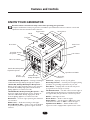 5
5
-
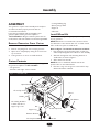 6
6
-
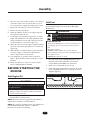 7
7
-
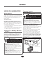 8
8
-
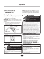 9
9
-
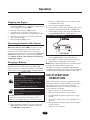 10
10
-
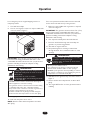 11
11
-
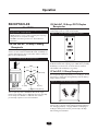 12
12
-
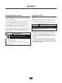 13
13
-
 14
14
-
 15
15
-
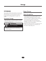 16
16
-
 17
17
-
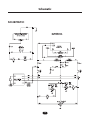 18
18
-
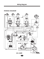 19
19
-
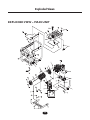 20
20
-
 21
21
-
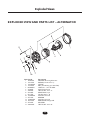 22
22
-
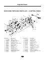 23
23
-
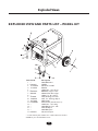 24
24
-
 25
25
-
 26
26
-
 27
27
-
 28
28
-
 29
29
-
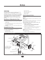 30
30
-
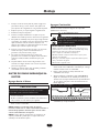 31
31
-
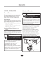 32
32
-
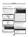 33
33
-
 34
34
-
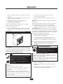 35
35
-
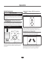 36
36
-
 37
37
-
 38
38
-
 39
39
-
 40
40
-
 41
41
-
 42
42
-
 43
43
-
 44
44


Simplicity 01935-0 Manual de usuario
- Categoría
- Accesorios para vehículos de motor
- Tipo
- Manual de usuario
En otros idiomas
- English: Simplicity 01935-0 User manual
Documentos relacionados
-
Simplicity 01935-1 Manual de usuario
-
-
-
Simplicity PRO6500 Manual de usuario
-
-
-
-
-
-