American Hearth EBL34 El manual del propietario
- Categoría
- Chimeneas
- Tipo
- El manual del propietario
Este manual también es adecuado para

Owner’s Manual
Model
EBL34
7213990200R02
IMPORTANT SAFETY INFORMATION: Always read this manual rst
before attempting to install or use this replace. For your safety, always
comply with all warnings and safety instructions contained in this manual
to prevent personal injury or property damage.
To view the full line of Empire products, please visit
www.empirecomfort.com

2 www.empirecomfort.com
Table of Contents
Always use a qualied technician or
service agency to repair this replace.
!
NOTE: Procedures and
techniques that are considered
important enough to emphasize.
CAUTION: Procedures and
techniques which, if not carefully
followed, will result in damage to
the equipment.
WARNING: Procedures and
techniques which, if not carefully
followed, will expose the user to
the risk of re, serious injury, or
death.
Welcome & Congratulations ..................3
IMPORTANT INSTRUCTIONS ................4
Quick Reference Guide ......................6
Fireplace Installation ........................7
Site Selection ................................ 7
Wiring ...................................... 8
Grounding Instructions ......................... 8
Hardwire Installation ........................... 9
For Bathroom Use ...........................10
Surface Mount Installation .....................10
Partial Recessed Installation - 2x4 Framing ........12
Flush Mounted Installation - 2x8 Framing. . . . . . . . . . 13
Front Glass Installation ........................15
Operation ................................16
Maintenance .............................19
Warranty ................................20

3
Welcome & Congratulations
Thank you and congratulations for purchasing an electric replace from
Empire.
Serial Number
Label
Rating Label with
Model Number
Please carefully read and save these instructions.
CAUTION: Read all instructions and warnings carefully before
starting installation. Failure to follow these instructions may result in
a possible electric shock, re hazard and will void the warranty.
NO NEED TO RETURN TO THE STORE
If you have general questions about our products, please e-mail us at
If you have a service or repair question, please contact your dealer.

4 www.empirecomfort.com
When using electrical appliances,
basic precautions should always be
followed to reduce the risk of fire,
electric shock, and injury to per-
sons, including the following:
① Read all instructions before us-
ing this electric replace.
② This replace is hot when in use.
To avoid burns, do not let bare skin
touch hot surfaces. The trim around
the heater outlet becomes hot dur-
ing heater operation.
DANGER: High temperatures
may be generated under certain
abnormal conditions. Do not
partially or fully cover or obstruct
the front of this heater.
③ Extreme caution is necessary
when any heater is used by or near
children or invalids and whenever
the unit is left operating and unat-
tended.
④ Young children should be su-
pervised to ensure that they do not
play with the appliance.
⑤ The appliance is not intended for
use by young children or inrmed
persons without supervision.
⑥ Do not operate the unit after it
malfunctions. Disconnect power at
the service panel and have the unit
inspected by a reputable electrician
before reusing.
IMPORTANT INSTRUCTIONS
⑦ If the supply cord is damaged,
it must be replaced by the manu-
facturer, or its service agent, or a
qualied person in order to avoid a
hazard.
⑧ Do not use outdoors.
⑨ Never locate replace where
it may fall into a bathtub or other
water container.
⑩ To disconnect the replace, turn
the controls o, and turn o power
to heater circuit at main disconnect
panel.
⑪ Do not run the cord under car-
peting. Do not cover cord with throw
rugs, runners, or the like. Arrange
cord away from trac area and
where it will not be tripped over.
⑫ Do not locate the heater immedi-
ately below a xed socket-outlet.
⑬ Do not insert or allow foreign
objects to enter any ventilation or
exhaust opening as this may cause
an electric shock or re, or damage
to the heater.
⑭ To prevent a possible fire, do not
block air intakes or exhaust in any
manner.
⑮ All electrical heaters have hot
and arcing or sparking parts inside.
Do not use in areas where gaso-
line, paint, or ammable liquids are
used or stored.

5
SAVE THESE INSTRUCTIONS
⑯ Use this replace only as
described in this manual. Any
other use not recommended by the
manufacturer may cause re, elec-
tric shock or injury to persons.
⑰ Do not change the plug in any
way. Always plug heaters directly
into a wall outlet/receptacle. Never
use with an extension cord or
relocatable power tap (outlet/power
strip).
⑱ Do not burn wood or other mate-
rials in the electric replace.
⑲ Do not strike the replace glass.
⑳ Always use a certied electrician
should new circuits or outlets be
required.
㉑ Always use properly grounded,
fused and polarized outlets.
㉒ Disconnect all power supply
before performing any cleaning,
maintenance or relocation of the
unit.
㉓ When transporting or storing the
unit and cord, keep in a dry place,
free from excessive vibration and
store so as to avoid damage.
WARNING: Remote control con-
tains small batteries. Keep away
from children. If swallowed, seek
medical attention immediately.
WARNING: Do not install bat-
tery backwards, charge, put in
re or mix with used or other
battery types - may explode or
leak causing injury.
!
NOTE: Changes or modica-
tions not expressly approved by
the party responsible for compli-
ance could void user's authority
to operate the equipment.
CAUTION
RISK OF ELECTRIC SHOCK
DO NOT OPEN
NO USER-SERVICABLE PARTS INSIDE
IMPORTANT INSTRUCTIONS

6 www.empirecomfort.com
Quick Reference Guide
Figure 1
1. The electrical information
regarding your electric replace
can be found on the rating label
located on the front of the unit,
behind the glass.
2. If you have any technical
questions or concerns regarding
the operation of your electric
replace, or require service
contact customer service at
1-888-346-7539.
3. For dimensions of your replace,
refer to Figure 1.
34.1 in.
(867 mm)
19.4 in.
(494 mm)
7.0 in.
(179 mm)
32.4 in.
(823 mm)
30.0 in.
(761 mm)
6.8 in.
(172 mm)
18.0 in.
(457 mm)
16.0 in.
(406 mm)
3.8 in.
(95 mm)

7
Site Selection
Review and consider all of the
following conditions before installation:
• Dimensions of the unit: 34.1 in.
(867 mm) x 19.4 in. (494 mm)
• For surface installation, the unit
requires a minimum of 2 wall
studs in order to ensure secure
installation. For other installation
methods, suitable framing is
required.
There are three possible mounting
methods:
• Surface mount (pg. 10);
• Partial Recessed (pg. 11);
• Flush mount (pg. 12),
and any of these have the option of
being hard-wired or plugged directly
into the wall outlet.
WARNING: The top of the
replace is to be installed at least
4" (10.2 cm) from the ceiling.
CAUTION: Ensure installation
does not allow replace to be in
direct contact with building vapor
barrier or insulation and meets all
local building code.
!
NOTE 1: A 15 Amp, 120 Volt
circuit is required. A dedicated
circuit is preferred but not
essential in all cases. A dedicated
circuit will be required if, after
installation, the circuit breaker
trips or fuse blows on a regular
basis when the heater is
operating. Additional appliances
Fireplace Installation
on the same circuit may exceed
the current rating of the circuit
breaker.
WARNING: Ensure the power
cord is not installed so that it is
pinched or against a sharp edge
and ensure that the power cord is
stored or secured to avoid tripping
or snagging to reduce the risk
of re, electric shock or injury to
persons.
Construction and electrical
outlet wiring must comply with
local building codes and other
applicable regulations to reduce
the risk of re, electric shock and
injury to persons.
WARNING: To reduce the risk of
re, do not store or use gasoline
or other ammable vapors or
liquids in the vicinity of the heater.
1. Select a location that is not
susceptible to moisture and is
away from drapes, furniture and
high trac.
2. For ease of electrical hook up you
may wish to locate the replace
near an existing outlet (for plug-in
convenience) (refer to NOTE 1).
3. Remove replace, front glass
and hardware from the box and
remove all packaging materials
before installation.
4. Store the replace in a safe, dry
and dust free location until you
are ready to install the replace.

8 www.empirecomfort.com
Fireplace Installation
Grounding Instructions
This product must be grounded. If it
should malfunction or breakdown,
grounding provides a path of least
resistance for electric current to
reduce the risk of electric shock.
This product is equipped with a cord
having an equipment-grounding
conductor and a grounding plug.
The plug must be plugged into an
appropriate outlet that is properly
installed and grounded in accordance
with all local codes and ordinances.
DANGER: Improper connection
of the equipment-grounding
conductor can result in a risk
of electric shock. Check with a
qualied electrician or serviceman
if you are in doubt as to whether
the product is properly grounded.
Do not modify the plug provided
with the product – if it will not t
the outlet, have a proper outlet
installed by a qualied electrician.
This product is for use on a nominal
AC/DC ADAPTER
RELAY BOARD
SWITCH BOARD
DISPLAY / CONTROL BOARD
LINE
NEUTRAL
HTR
THERMISTOR
LED STRIPS (RGB) - MEDIA
FLAME LED STRIP (AMBER)
M
ELEMENT
ELEMENT
CUTOUT
THERMAL
M
FLICKER MOTOR
BLOWER MOTOR
LED STRIPS (RGB) - FLAME
Wiring
120-volt circuit and has a grounding
plug that looks like the plug in Figure
1. Make sure that the product is
connected to an outlet having the
same conguration as the plug. No
adapter should be used with this
product.
Figure 2

9
Figure 3
Screws
Electrical
Cord Bracket
Hardwire
Bracket
Fireplace Installation
Hardwire Installation
The replace is provided with a
three prong plug installed for plug-
in convenience. Hard wiring the
replace is also an option for any
installation.
WARNING: Do not attempt to wire
your own new outlets or circuits. To
reduce the risk of re, electric shock
or injury to persons, always use a
licensed electrician.
WARNING: Ensure that the
circuit on which the replace is
to be installed has the power
cut o at the service panel until
installation is complete.
1. Carefully remove the electrical
cord bracket from the back of the
replace by removing the three
retaining screws. (Figure 3)
2. Remove the wire access cover o
of the unit at the front to access
the wire connections. (Figure 4)
3. Pull the wires and connectors out
of the back opening.
4. Unscrew the three wire
connectors inside the electrical
box and separate the wires.
5. Install the supplied hardwire
bracket (with the ½" wire hole)
onto the rebox. (Figure 3)
6. Leaving a minimum of 3 in.
(7.6 cm) of slack, route the power
supply wires through the hole in
the electrical cover bracket and
secure with a wire clamp (not
supplied).
7. Connect the black wire (L) from
the unit to the live wire from the
power supply using one of the wire
connectors removed in step 4.
8. Connect the blue and white wires
(N) from the unit to the neutral
wire from the power supply using
the second wire connector from
step 4.
Figure 4
Wire Access
Cover

10 www.empirecomfort.com
Fireplace Installation
Surface Mount Installation
CAUTION: Two people may be
required for various steps of this
procedure.
1. Choose your method of supplying
power to the unit:
• Plug in to an existing outlet or
install an outlet nearby.
• Hard wire the replace. Follow the
hard wiring instructions on page 8.
WARNING: Do not attempt to wire
your own new outlets or circuits. To
reduce the risk of re, electric shock
or injury to persons, always use a
licensed electrician.
WARNING: Ensure that the circuit
on which the replace is to be
installed has the power cut o at
the service panel until installation
is complete.
2. Determine the mounting location
of the unit so that the wall
mounting bracket can be installed
into 2 wall studs.
!
NOTE: It is recommended that
the mounting bracket be installed
56 in. (142 cm) o of the ground
to maintain an optimized viewing
angle of the ame.
3. Hold the wall mounting bracket,
with the bubble level on the top,
on the wall so that the bubble on
the level is centered between the
two black lines.
9. Connect the green wire (G) from
the unit to the ground wire from
the power supply using the third
wire connector from step 4.
10. Reposition the wire access covers
over the wires and connectors
and attach to replace chassis
using the screws removed in step
2.
11. Refer to Front Glass Installation
section for nal installation
procedures.
For Bathroom Use
If this unit is installed in a bathroom
it must be protected by a GFI
receptacle or circuit. If receptacle is
used it must be readily accessible.
To prevent electrical shock this unit
is an electrical appliance that is NOT
watertight and must be installed as to
prevent water from entering unit. This
must be installed away from showers,
tubs, etc. Never locate replace
where it may fall into a bathtub or
other water container.

11
Fireplace Installation
4. Mark the 3 mounting screw
locations, on the wall, ensuring
that the wall bracket stays level.
(Figure 5)
5. In locations where the screws are
being installed only into drywall,
install the supplied wall anchors
before installing the screw (predrill
if required).
6. Secure the wall bracket to the wall
using the supplied 1½ in. (3.8 cm)
mounting screws and washers
into the wall and/or wall anchors.
7. Install the bottom support bracket
to the wall centered with the
wall mounting bracket, using the
appropriate mounting hardware,
13 ¾" (350 mm) below the wall
mounting bracket. (Figure 5)
Figure 6
Figure 5
Wall Mounting
Bracket
Bottom Support
Bracket
8. Remove the center back screw
from the bottom of the replace.
(Figure 6)
9. Hang the replace from the
bracket.
10. Install the removed screw through
the bottom support bracket into
the replace.
11. Refer to Front Glass Installation
section for nal installation
procedures.

12 www.empirecomfort.com
Fireplace Installation
Partial Recessed
Installation - 2x4 Framing
CAUTION: Two people may be
required for various steps of this
procedure.
1. Prepare a wall with a framed
opening of 30 ½ in. (77.5 cm)
wide x 16 ½ in. (42 cm) high
(Figure 7).
!
NOTE: The sizing has allowed
for ¼ in. (6.4 mm) around the
replace insert for ease of
installation. This replace does
not require any additional venting.
!
NOTE: It is recommended that
the bottom of the unit not be
mounted higher than 40 in. (102
cm) from the ground to maintain
an optimized viewing angle of the
ame.
2. Choose your method of supplying
power to the unit:
• Plug in (you may run the power
cord out of the framed wall
opening to an existing outlet or
install an outlet on a nearby wall
stud within the wall).
• Hard wire the replace
(recommended). Follow the hard
wiring instructions on page 8.
WARNING: Do not attempt to wire
your own new outlets or circuits. To
reduce the risk of re, electric shock
or injury to persons, always use a
licensed electrician.
WARNING: Ensure that the circuit
on which the replace is to be
installed has the power cut o at
the service panel until installation
is complete.
3. Lift replace and insert into
opening (Figure 8).
4. Use the supplied bubble level
to level the replace within the
framing, adjust as required.
5. Drive four supplied mounting
screws through the four mounting
holes located in each corner of the
replace chassis, into wall studs
(Figure 8).
6. Refer to Front Glass Installation
section for nal installation
procedures.
Figure 7
2 x 4 Framing

13
Figure 9
2 x 8 Framing
Fireplace Installation
Flush Mounted
Installation - 2x8 Framing
CAUTION: Two people may be
required for various steps of this
procedure.
1. Prepare a wall with a framed
opening of 33 in. (83.8 cm) wide x
18 ½ in. (47 cm) high (Figure 9).
!
NOTE: The sizing has allowed
for ¼ in. (6.4 mm) around the
replace insert for ease of
installation. This replace does
not require any additional venting.
!
NOTE: It is recommended that
the bottom of the unit not be
mounted higher than 40 in. (102
cm) from the ground to maintain
an optimized viewing angle of the
ame.
Figure 8
Mounting hole
Mounting
holes
2. Choose your method of supplying
power to the unit:
• Plug in (you may run the power
cord out of the framed wall
opening to an existing outlet or
install an outlet on a nearby wall
stud within the wall).
• Hard wire the replace
(recommended). Follow the hard
wiring instructions on page 8.
WARNING: Do not attempt to wire
your own new outlets or circuits. To
reduce the risk of re, electric shock
or injury to persons, always use a
licensed electrician.
WARNING: Ensure that the circuit
on which the replace is to be
installed has the power cut o at
the service panel until installation
is complete.

14 www.empirecomfort.com
Fireplace Installation
3. Lift replace and insert into opening.
The replace's mounting trim should
be ush against the wall (Figure 9).
4. Use the supplied bubble level
to level the replace within the
framing, adjust as required.
5. Drive four supplied mounting
screws through the four mounting
holes located on the inside surface
of the replace chassis, into wall
studs (Figure 10).
6. Refer to Front Glass Installation
section for nal installation
procedures.
Figure 10
Mounting hole
Mounting hole
Wall
surface

15
Figure 11
Front tray
Front glass
assembly
Figure 12
Tab
Hooks (4)
Mounts (4)
Front Glass Installation
1. Pour and evenly distribute the
supplied media in the Media tray
of the firebox (Figure 11).
2. Carefully mount front glass
assembly so that the front
glass hooks hang on the front
glass mounts on the fireplace
(Figure 11).
3. Use the supplied two Phillips
sheet metal screws to fasten
the glass assembly tabs to the
fireplace (Figure 12).
4. If unit is not hard-wired, plug
fireplace into a 15 Amp, 120 Volt
outlet (refer to NOTE 1).

16 www.empirecomfort.com
Display
TM
for 5 seconds.
B. Flame Eects
Turns the ame eect On and O.
→ Activated by pressing the
but-
ton on the remote.
C. Heat ON/OFF
Turns the heater On and O.
→ Activated by pressing the
but-
ton on the unit or the remote.
• Indicated by the
icon and the
intake temperature being displayed
on the Floating Display
TM
, for 5
seconds before turning off.
!
NOTE: After the heater is
switched o, there is a 60 second
fan delay, where the fan will con-
tinue running before turning o.
!
NOTE: The unit can be oper-
ated in Heat Only Mode. When
the unit is only running with the
heater, the
icon will continu-
ously be displayed on the Floating
Figure 13
WARNING: This electric rebox
must be properly installed before it
is used.
The unit can be controlled by either
the manual controls which are located
on the upper right of the replace or
the remote (Figure 13 & 14).
The replace is supplied with an IR
multifunction remote control.
!
NOTE: To operate correctly, the
remote control must be pointed
towards the Floating Display
TM
.
A. Standby
Turns the unit On and O.
→ Activated by pressing the Standby
button on the remote or the unit.
• The unit will turn on with the same
functions that it was set to when
it was turned O and the intake
temperature will be indicated on
the Floating Display
TM
.
!
NOTE: When any button is
pressed the intake temperature
will be displayed on the Floating
Operation
A C D E
F
Floating
Display
TM
Figure 14
A
D
B
C
E
G
H
F

17
Operation
Display
TM
.
!
NOTE: The heater may emit a
slight, harmless odor when rst
used. This odor is a normal condi-
tion caused by initial heating of
internal heater parts and will not
occur again.
D & E.
Thermostat Controls
Adjusts the temperature set point
to your individual requirements.
Once the desired set temperature is
reached the heater will turn off. The
heater will cycle on and off to main-
tain the desired set temperature. The
default temperature setting is 72°F
(22°C).
→ Adjusted by pressing the
to
decrease the setpoint and the
to increase the setpoint on the unit
or the remote.
• The Floating Display
TM
will indicate
the temperature setpoint as it is
adjusted.
!
NOTE: Holding the and the
buttons down for two sec-
onds, on the unit, will change the
temperature from °C to °F, or vice
versa.
Disable Heat
If desired, depending on the sea-
son, the heater on the unit can be
disabled. The unit will operate in the
same fashion, with remainder of the
controls.
Pressing the
and buttons on
the unit at the same time and holding
for 2 seconds will disable and enable
the heater.
!
NOTE: When the heater has been
disabled and either the
or the
is pressed the Floating DisplayTM will
indicate "--".
F. Color Themes
Dierent presets of ambient lighting
color combinations contained in the
unit.
→ Changed by repeatedly pressing
the corresponding button on the
remote or the unit.
• Cycles through the dierent preset
ambient lighting settings of the
unit, this includes dierent com-
binations of colours of the ame
base and media lighting.
!
NOTE: The last theme of the cycle
is a prism where the unit cycles
through a variety of colours.
Pressing the
button stops the
cycling and holds the unit on the
preferred color, indicated by a "U"
- Unfreeze or a "F" - Freeze on
the display.

18 www.empirecomfort.com
Operation
G.
Brightness
Changes the brightness of the lights
in the unit.
→ Adjusted by repeatedly pressing
the corresponding button on the
remote.
• Indicated by the second digit on
the Floating Display™ changing to
show: "H" (high), and "L" (low).
H. Sleep Timer
The Sleep Timer can be set to auto-
matically shut o the replace after
a preset time (from 30 minutes to 8
hours).
→ To set the timer press the timer
button on the remote, repeatedly,
until the desired time is displayed.
• The Floating Display
TM
will display
the dierent times as it is adjusted.
Once the timer has begun, press-
ing the
button will display the
time remaining before the unit
turns O.
!
NOTE: The Sleep Timer can be
cancelled at any time by pressing
the
button repeatedly until the
sleep timer displays nothing.
Resetting the Temperature
Cuto Switch
Should the heater overheat, an
automatic cut out will turn the whole
unit o and it will not come back on
without being reset. It can be reset
by turning the power to the unit and
waiting 5 minutes before turning the
unit back on.
CAUTION: If you need to continu-
ously reset the heater, unplug the
unit and call technical support at
1-888-346-7539.
Remote Control Battery
Replacement
To replace the battery:
1. Slide battery cover open on the
remote control.
2. Correctly install one 3 Volt
(CR2032 [longer life] or CR2025)
battery in the battery holder.
3. Close the battery cover.
Battery must be recycled or
disposed of properly. Check
with your Local
Authority or Retailer for recycling
advice in your area

19
Maintenance
Fireplace Surface Cleaning
Use only a damp cloth to clean
painted surfaces of the replace.
Do not use abrasive cleaners.
Servicing
Except for installation and
cleaning described in this
manual, an authorized service
representative should perform
any other servicing.
WARNING: Disconnect
power before attempting any
maintenance or cleaning to
reduce the risk of re, electric
shock or damage to persons.
!
NOTE: The replace should
not be operated with an
accumulation of dust or dirt
on or in the unit, as this can
cause a build up of heat and
eventual damage. For this
reason the heater must be
inspected regularly, depending
upon conditions and at least at
yearly intervals.
Partially Reective Glass
Cleaning
The partially reective glass is
cleaned in the factory during
the assembly operation. During
shipment, installation, handling,
etc., the partially reective glass
may collect dust particles; these
can be removed by dusting lightly
with a clean dry cloth.
To remove ngerprints or other
marks, the partially reective
glass can be cleaned with a damp
cloth. The partially reective glass
should be completely dried with
a lint free cloth to prevent water
spots. To prevent scratching, do
not use abrasive cleaners.

20 www.empirecomfort.com
Products to which this limited warranty
applies
This limited warranty applies to your newly
purchased Empire electric replace. This
limited warranty applies only to purchases
made in any of the 50 States of the USA
(and the District of Columbia) except for
Hawaii and Alaska. This limited warranty
applies to the original purchaser of the
product only and is not transferable.
Products excluded from this limited war-
ranty
Products purchased in Hawaii or Alaska
are not covered by this limited warranty.
Products purchased in these States are
sold AS IS without warranty or condition
of any kind (including, without limitation,
any implied warranties or conditions of
merchantability or tness for a particular
purpose) and the entire risk of as to the
quality and performance of the products is
with the purchaser, and in the event of a
defect the purchaser assumes the entire
cost of all necessary servicing or repair.
What this limited warranty covers and for
how long
Products, other than replace surrounds
(mantels) and trims, covered by this
limited warranty have been tested and
inspected prior to shipment and, subject
to the provisions of this warranty, Empire
warrants such products to be free from
defects in material and workmanship for a
period of 2 years from the date of the rst
purchase of such products.
Empire replace surrounds (mantels) and
trims covered by this limited warranty have
been tested and inspected prior to ship-
ment and, subject to the provisions of this
warranty, Empire warrants such products
to be free from defects in material and
workmanship for a period of 1 year from
the date of rst purchase of such products.
The limited 2 year warranty period for
products other than replace surrounds
(mantels) and trims and the limited 1 year
warranty period for replace surrounds
(mantels) and trims also applies to any
implied warranties that may exist under
applicable law. Some jurisdictions do not
allow limitations on how long an implied
warranty lasts, so the above limitation may
not apply to the purchaser.
What this limited warranty does not cover
This limited warranty does not apply to
products that have been repaired (except
by Empire or its authorized service rep-
resentatives) or otherwise altered. This
limited warranty does further not apply
to defects resulting from misuse, abuse,
accident, neglect, incorrect installation, im-
proper maintenance or handling, or opera-
tion with an incorrect power source.
What you must do to get service under
this limited warranty
If you have a service or repair question,
please contact your dealer. Please have
proof of purchase, catalogue/model and
serial numbers available when calling.
Limited warranty service requires a proof
of purchase of the product.
What Empire will do in the event of a de-
fect
In the event a product or part covered by
this limited warranty is proven to be defec-
tive in material or workmanship during (i)
the 2 year limited warranty period for prod-
ucts other than replace surrounds (man-
tels) and trims, and (ii) the 1 year limited
warranty period for surrounds (mantels)
and trims, you have the following rights:
• Empire will in its sole discretion either
repair or replace such defective product
or part without charge. If Empire is un-
able to repair or replace such product
or part, or if repair or replacement is
not commercially practicable or cannot
be timely made, Empire may, in lieu of
repair or replacement, choose to refund
the purchase price for such product or
part.
• Limited warranty service will be per-
formed solely by dealers or service
agents of Empire authorized to provide
Warranty

21
limited warranty services.
• For products other than surrounds
(mantels) and trims, this 2 year limited
warranty entitles the purchaser to on-
site or in-home warranty services. Ac-
cordingly, Empire will be responsible for
all labour and transportation associated
with repairing or replacing the product
or part except as follows: (i) charges
which may be levied for travel costs
incurred to travel to the purchaser’s
site where the product is located if the
purchaser’s site is beyond 30 miles (48
km) from the closest service depot of
Empire’s dealer or service agent; and
(ii) the purchaser is solely responsible
for providing clear access to all service-
able parts of the product.
• For surrounds (mantels) and trims, this
1 year limited warranty does not entitle
the purchaser to on-site or in-house
warranty services. The purchaser is
responsible for removal and transpor-
tation of the surrounds (mantels) and
trims (and any repaired or replacement
product or part) to and from the autho-
rized dealer’s or service agent’s place
of business. On-site or in-home services
for surrounds (mantels) and trims may
be performed at the purchaser’s spe-
cic request and expense at Empire’s
then current rates for such services.
Empire will not be responsible for, and
this limited warranty shall not include,
any expense incurred for installation
or removal of the surrounds (mantels)
or trims or any part thereof (or any re-
placement product or part) including,
without limitation, all shipping costs and
transportation costs to and from the
authorized dealer’s or service agent’s
place of business and all labour costs.
Such costs shall be the purchaser’s re-
sponsibility.
What Empire and its dealers and service
agents are also not responsible for:
IN NO EVENT WILL EMPIRE, OR ITS
DIRECTORS, OFFICERS, OR AGENTS,
BE LIABLE TO THE PURCHASER OR
ANY THIRD PARTY. WHETHER IN CON-
TRACT, IN TORT, OR ON ANY OTHER
BASIS, FOR ANY INDIRECT, SPECIAL,
PUNITIVE, EXEMPLARY, CONSEQUEN-
TIAL, OR INCIDENTAL LOSS, COST,
OR DAMAGE ARISING OUT OF OR IN
CONNECTION WITH THE SALE, MAIN-
TENANCE, USE, OR INABILITY TO
USE THE PRODUCT, EVEN IF EMPIRE
OR ITS DIRECTORS, OFFICERS, OR
AGENTS HAVE BEEN ADVISED OF
THE POSSIBILITY OF SUCH LOSSES,
COSTS OR DAMAGES, OR IF SUCH
LOSSES, COSTS, OR DAMAGES ARE
FORESEEABLE. IN NO EVENT WILL EM-
PIRE, OR ITS OFFICERS, DIRECTORS,
OR AGENTS BE LIABLE FOR ANY DI-
RECT LOSSES, COSTS, OR DAMAGES
THAT EXCEED THE PURCHASE PRICE
OF THE PRODUCT.
SOME JURISDICTIONS DO NOT ALLOW
THE EXCLUSION OR LIMITATION OF IN-
CIDENTAL OR CONSEQUENTIAL DAM-
AGES, SO THE ABOVE LIMITATION OR
EXCLUSION MAY NOT APPLY TO THE
PURCHASER.
How State and Provincial law apply
This limited warranty gives you specic
legal rights, and you may also have other
rights which vary from jurisdiction to juris-
diction. The provisions of the United Na-
tions Convention on Contracts for the Sale
of Goods shall not apply to this limited
warranty or the sale of products covered
by this limited warranty.
Warranty

22 www.empirecomfort.com
Empire Comfort Systems Inc.
Belleville, IL
If you have general questions about our
products, please e-mail us at
If you have a service or repair question,
please contact your dealer.

Manual del propietario
Modelo
EBL34
7213990200R02
INFORMACIÓN IMPORTANTE DE SEGURIDAD: Siempre lea este manual
antes de intentar instalar o usar esta chimenea. Por su seguridad, cumpla
siempre con todas las advertencias e instrucciones de seguridad que se incluyen
en este manual para evitar lesiones y daños materiales.
Para ver toda la línea de productos Empire, visite www.empirecomfort.com

2 www.empirecomfort.com
Índice
Siempre consulte con un técnico
calicado o una agencia de servicio
para reparar esta chimenea.
!
NOTA: Procedimientos y
técnicas importantes a tomar en
cuenta.
PRECAUCIÓN: Procedimientos
y técnicas que, si no se respetan
escrupulosamente, resultará en
daños el equipo.
ADVERTENCIA: Procedimientos
y técnicas que, si no se respetan
escrupulosamente, expondrán al
usuario a un riesgo de incendio,
lesiones graves o la muerte.
Bienvenido y felicitaciones ...................3
INSTRUCCIONES IMPORTANTES ...........4
Guía de consulta rápida .....................6
Instalación de la chimenea ...................7
Selección de la ubicación ........................... 7
Para conectar a tierra .............................. 8
Instalación de la conexión alámbrica .................. 9
Para usarse en el baño ............................ 10
Instalación del montaje de supercie ...................11
Instalación semi-empotrada - marco de 2x4 ............ 12
Instalación empotrada - marco de 2x8 ................. 14
Instalación del cristal delantero ...................... 15
Funcionamiento. . . . . . . . . . . . . . . . . . . . . . . . . . . 16
Mantenimiento. . . . . . . . . . . . . . . . . . . . . . . . . . . . 20
Garantía ................................21

3
Bienvenido y felicitaciones
Gracias y felicitaciones por haber adquirido una chimenea eléctrica Empire
Etiqueta del
número de serie
Etiqueta de clasicación con
el número de modelo
Lea atentamente y guarde estas instrucciones.
PRECAUCIÓN: Antes de comenzar la instalación, asegúrese de leer
las instrucciones y advertencias cuidadosamente. No seguir estas
instrucciones podría provocar una descarga eléctrica, un incendio y la
anulación de la garantía.
NO ES NECESARIO REGRESAR A LA TIENDA
Si tiene preguntas generales sobre nuestros productos, envíenos un correo
electrónico a [email protected].
Si tiene alguna pregunta sobre servicio o reparación, comuníquese con su
distribuidor.

4 www.empirecomfort.com
Cuando se usen aparatos eléctricos,
deben respetarse una serie de pre-
cauciones básicas a n de aminorar
el riesgo de incendio, descarga eléc-
trica y lesiones personales.
① Lea todas las instrucciones antes
de usar la chimenea sobrepuesta/
empotrable.
② La chimenea se pone caliente al
usarla. Para evitar quemaduras, no
toque las supercies calientes con
la piel al aire. El material situado
alrededor de la salida de aire de la
chimenea se calienta durante su
funcionamiento.
PELIGRO: Las temperaturas
altas se peuden generar bajo
ciertas condiciones anormales.
No parcialmente o completamen-
te la cubierta u obstruir el frente
de este calentador.
③ Hay que extremar la precaución
cuando se use cualquier calentador
de aire cerca de los niños o inválidos
o bien sean ellos quienes lo manejen
y siempre que se deje el aparato en
funcionamiento y sin vigilancia.
④ Debe vigilarse atentamente a los
niños para asegurarse de que no
jueguen con el aparato.
⑤ El aparato no ha sido diseñado
para ser manejado por niños ni per-
sonas inválidas sin supervisión.
⑥ No opere ningún calentador de
aire si no funciona correctamente.
Desconecte la electricidad a partir
del panel central y haga vericar la
unidad por un electricista acreditado
antes de volver a utilizarla.
INSTRUCCIONES IMPORTANTES
⑦ No haga funcionar la chimenea
eléctrica si el cable de alimentación o
el enchufe están dañados o si el ca-
lentador no funciona bien o si se ha
caído o dañado de cualquier manera.
⑧ No lo use a la intemperie.
⑨ No coloque la chimenea en aque-
llos sitios donde pueda caer en una
bañera o en cualquier otro recipiente
de agua.
⑩ Para desconectar la chimenea,
apague los controles, y luego quite el
enchufe del tomacorriente o desco-
necte el circuito en el tablero principal
de desconexión.
⑪ No tienda el cable debajo de
alfombras. No cubra el cable con
tapetes, corredores u otras alfombri-
llas similares. Disponga el cable lejos
de las áreas transitadas y donde no
ocasione un riesgo de tropiezos.
⑫ No sitúe el calentador debajo
de un tomacorriente o una caja de
conexión fija.
⑬ No inserte ni permita que ningún
objeto entre en los orificios de ventila-
ción o de escape, ya que esto puede
provocar una descarga eléctrica o un
incendio, o bien ocasionar daños al
calentador.
⑭ Para evitar cualquier posible
incendio, no bloquee la entrada ni la
salida de aire bajo ninguna circuns-
tancia.
⑮ Todos los calentadores contienen
piezas calientes que provocan chis-
pas o arcos eléctricos. No lo utilice

5
en zonas en las que se empleen o
almacene gasolina, pintura o líquidos
inamables.
⑯ Utilícese la chimenea eléctrica
sólo como se indica en este manual.
Cualquier otro uso que no haya sido
recomendado por el fabricante puede
provocar un incendio, una descarga
eléctrica o lesiones físicas.
⑰ No cambie el enchufe bajo ningún
concepto. Siempre enchufe los calen-
tadores de aire directamente a una
toma corriente de pared/enchufe. No
utilice nunca un cable de extensión ni
una conexión eléctrica relocalizable
(toma de corriente/barra de alimen-
tación).
⑱ No queme madera ni otros mate-
riales en la chimenea.
⑲ No golpee la parte frontal de
cristal.
⑳ En caso de requerirse nuevos
circuitos o tomacorrientes, acuda
siempre a un electricista calificado.
㉑ Use siempre enchufes polariza-
dos, bien puestos a tierra y dotados
de fusibles.
㉒ Desconecte el suministro de
corriente (desconecte el aparato o
corte el interruptor general) antes
de limpiar el aparato, mantenerlo o
cambiarlo de sitio.
㉓ Cuando se transporten o alma-
cenen el aparato y el cable, man-
téngalos en un sitio seco y libre de
vibraciones excesivas, y almacena-
dos de modo que se evite cualquier
perjuicio.
ADVERTENCIA: El control remo-
to contiene baterías pequeñas.
Manténgalo alejado de los niños.
Si se ingiere, consulte con un
médico inmediatamente.
ADVERTENCIA: No coloque las
baterías al revés, no las cargue,
no las incinere ni las mezcle
con otro tipo de baterías ya que
podrían explotar o tener fugas,
ocasionando lesiones.
!
NOTA: Los cambios o las mo-
dicaciones que no hayan sido
expresamente aprobados por el
responsable del cumplimiento,
podrían anular la autorización que
el usuario tiene para utilizar dicha
unidad.
INSTRUCCIONES IMPORTANTES
GUARDE ESTAS INSTRUCCIONES
PRECAUCIÓN
RIESGO DE DESCARGA ELÉCTRICA - NO ABRIR
NO CONTIENE PARTES QUE EL USUARIO
PUEDA REPARAR

6 www.empirecomfort.com
Guía de consulta rápida
Figura 1
1. Toda información eléctrica sobre
su chimenea eléctrica la podrá
encontrar en la etiqueta de
clasicación localizada al frente
de la unidad, detrás del cristal.
2. Si tiene alguna pregunta
técnica o inquietud respecto al
funcionamiento de su chimenea
eléctrica, o si requiere servicio
técnico, comuníquese con el
servicio al cliente.
3. Consulte la Figura 1 para obtener
las dimensiones de la chimenea.
34.1 in.
(867 mm)
19.4 in.
(494 mm)
7.0 in.
(179 mm)
32.4 in.
(823 mm)
30.0 in.
(761 mm)
6.8 in.
(172 mm)
18.0 in.
(457 mm)
16.0 in.
(406 mm)
3.8 in.
(95 mm)

7
Selección de la ubicación
Revise y tome en cuenta las
condiciones siguientes antes de
instalación:
• Dimensiones de la unidad:
34.1 pulgadas (867 mm) x 19.4
pulgadas. (494 mm)
• Para la instalación de la supercie,
la unidad requiere un mínimo de
2 montantes de la pared con el
n de garantizar una instalación
segura. Para otros métodos de
instalación, se requiere encuadre
adecuado.
Puede montarla de tres maneras
diferentes:
• Montaje en supercie (pág. 11);
• Empotradas en la pared (pág. 12);
• Empotrada (pág. 14)
y todas cuentan con la opción de
conexión alámbrica permanente o de
directamente en el enchufe de pared.
ADVERTENCIA: La parte
superior de la chimenea eléctrica
debe ser instalada minimo a 4
pulgadas
(10.2 cm) del techo.
PRECAUCIÓN: Asegurar la
instalación no permite chimenea
para estar en contacto directo
con barrera de vapor edicio o de
aislamiento y cumple con todos
los códigos de construcción local.
!
NOTA 1: Se requiere un circuito
de 15 amperios y 120 voltios.
Instalación de la chimenea
Es preferible disponer de un
circuito exclusivo, pero no es
esencial en todos los casos. Si
después de instalar el calentador,
el disyuntor salta o el fusible
se funde con cierta frecuencia
durante el funcionamiento del
calentador, podría necesitar un
circuito exclusivo. Los aparatos
adicionales que se conecten
al mismo circuito podrían
sobrepasar la capacidad nominal
de corriente del disyuntor.
ADVERTENCIA: Asegúrese de
que el cable eléctrico no esté
instalado de manera que quede
prensado o aplastado contra un
borde loso, y asegúrese también
de que esté bien guardado o
sujeto para evitar tropiezos o
enganchones y reducir así el
riesgo de incendio, descarga
eléctrica o lesiones físicas.
La construcción y el cableado
eléctrico del tomacorriente deben
cumplir con las ordenanzas de
construcción municipales y con la
demás reglamentación aplicable
a n de reducir el riesgo de
incendio, descarga eléctrica y
lesiones físicas.
ADVERTENCIA: Para reducir el
riesgo de incendios, no almacene
o utilice gasolina o cualquier otro
vapor o líquido inamable cerca
del calentador.
1. Seleccione un sitio adecuado que

8 www.empirecomfort.com
Adaptador AC/DC
Carte de relais
Control Remoto tarjeta de circuitos interruptor
Tablero de control/pantalla
Línea
Neutro
HTR
Thermistor
Conjunto de luces LED (RVA) - rocas de cristal
Conjunto de luces LED (ámbar)
M
Elemento
Elemento
Protecciòn térmica
M
Motor del efecto de llama
Motor del ventilador
Conjunto de luces LED (RVA) - Llama
Instalación de la chimenea
no esté expuesto a la humedad,
que se encuentre alejado de
cortinas y mobiliario, y por el que
no se pase frecuentemente.
2. Para facilitar la conexión, puede
situar la chimenea cerca de
un enchufe ya existente (para
enchufarla fácilmente) (consulte la
NOTA 1).
3. Retire la chimenea, el cristal
delantero y las piezas de la caja
y quite todos los materiales de
empaque antes de la instalación.
4. Coloque la chimenea en un lugar
seguro, seco y libre del polvo
hasta que esté listo para instalarla.
Cableado
Para conectar a tierra
Este producto tiene que conectarse
a tierra. Si el producto no está
funcionando bien o está averiado,
el conectarlo a tierra proporciona
una ruta de menor resistencia para
que reducir la corriente eléctrica
y así disminuir el riesgo sufrir una
descarga eléctrica. Este producto
incluye un cable con un conductor
y un enchufe de conexión a tierra.
El enchufe debe conectarse a una
entrada debidamente instalada y
conectada a tierra de acuerdo con los
códigos y las ordenanzas locales.
PELIGRO: Si la conexión del
conductor a tierra del equipo no es
Figura 2

9
Figura 3
Soporte
para el cable
eléctrico
Soporte para
alambre permanente
Tornillo
Instalación de la chimenea
la correcta corre el riesgo de sufrir
una descarga eléctrica. Consulte
con un electricista calicado o
un técnico de servicio si no está
seguro de que la conexión a
tierra de este producto sea la
correcta. No modique el enchufe
proporcionado del producto, si
no cabe en el tomacorriente,
un electricista calicado deberá
instalar el tomacorriente
apropiado.
Este producto está diseñado para
utilizar un circuito nominal de 120v y
tiene un enchufe a tierra como el que
se muestra en la Figura 1. Asegúrese
de que el producto esté conectado a
un tomacorriente que tenga la misma
conguración que el enchufe. No use
ningún adaptador para este producto.
Instalación de la conexión alámbrica
La chimenea cuenta con un enchufe
de tres clavijas para enchufarlo
fácilmente. Para cualquier tipo de
instalación, existe la opción de una
conexión alámbrica permanente.
ADVERTENCIA: No
intente conectar circuitos ni
tomacorrientes nuevos. Para
reducir el riesgo de incendio,
descarga eléctrica o lesiones
físicas, acuda siempre a un
electricista certicado.
ADVERTENCIA: Asegúrese
de que se haya cortado la
alimentación en el panel de
servicio del circuito en el que se
debe instalar el calentador de aire
hasta nalizar la instalación.
1. Retire los tres tornillos y, con
cuidado, retire el cable eléctrico
de la parte trasera de la
chimenea.
(Figura 3)
2. Retire la tapa de la unidad ubicada
Figura 4
Acceso a
la cubierta
para cables

10 www.empirecomfort.com
Instalación de la chimenea
10. Coloque nuevamente la tapa
del soporte eléctrico sobre los
cables y conectores e inserte
en el chasis de la cámara de
combustión con los tornillos que
quitó en el paso 2.
11. Consulte la sección de instalación
del cristal delantero para conocer
el proceso nal de instalación.
Para usarse en el baño
Si instala esta unidad en el baño,
deberá contar con un receptáculo o
circuito con interruptor por fallo a tie-
rra. Si usa un receptáculo, éste debe
estar a la mano.
Esta unidad no es impermeable y
debe instalarse de manera que NO
entre en contacto con agua para
evitar descargas eléctricas. Debe ins-
talarse lejos de regaderas, tinas, etc.
Nunca coloque la chimenea en sitios
donde pueda caer en una bañera o
en otro recipiente con agua.
al frente para tener acceso a las
conexiones eléctricas. (Figura 4)
3. Tire hacia afuera los cables y
conectores de la abertura trasera.
4. Destornille los tres cables
conectores que se encuentran
dentro de la caja eléctrica y
sepárelos.
5. Instale el soporte para la conexión
permanente (con el oricio del
cable de ½ pulgada) hacia la
cámara de combustión. (Figura 3)
6. Dejando al menos 3 pulgadas
(7.6 cm) de holgura, dirija los
cables del suministro eléctrico por
el oricio en la tapa del soporte
eléctrico y asegure con una
abrazadera (no incluida).
7. Conecte el cable negro (L)
proveniente de la unidad al
cable bajo tensión del suministro
eléctrico usando uno de los
cables conectores que quitó en el
paso 4.
8. Conecte los cables azules
y blanco (N) proveniente de
la unidad al cable neutro del
suministro eléctrico usando el
segundo cable conector del paso
4.
9. Conecte el cable verde (G)
proveniente de la unidad al cable
tierra del suministro eléctrico
usando el tercera cable conector
del paso 4.

11
Instalación de la chimenea
Instalación del montaje de
supercie
PRECAUCIÓN: Se requiere de
dos personas para diferentes
pasos de este procedimiento.
1. Elija el método para suministrar
energía a la unidad:
• Conectarla en un enchufe
existente o instalar uno cerca de
la unidad.
• Para instalar el cableado
permanente para la chimenea.
Siga las instrucciones de
programación en la página 8.
ADVERTENCIA: No
intente conectar circuitos ni
tomacorrientes nuevos. Para
reducir el riesgo de incendio,
descarga eléctrica o lesiones
físicas, acuda siempre a un
Figura 6
Figura 5
Soporte de
pared
Soporte de apoyo
inferior
electricista certicado.
ADVERTENCIA: Asegúrese
de que se haya cortado la
alimentación en el panel de
servicio del circuito en el que se
debe instalar el calentador de aire
hasta nalizar la instalación.
2. Determine en dónde se va a
montar la unidad para que el
soporte de pared se instale en 2
vigas.
!
NOTA: Se recomienda que el
soporte para la montura se instale
a 56 pulgadas (142 cm) del piso
para optimizar el ángulo de visión
de la ama.
3. Con el nivel de burbuja en la parte
superior, coloque en la pared el
soporte de montaje de pared de
modo que la burbuja del nivel
quede centrada entre las dos
líneas negras.
4. Marque las 3 posiciones
de los tornillos de montaje,

12 www.empirecomfort.com
Instalación de la chimenea
asegurándose de que el soporte
de pared permanezca nivelado.
(Figura 5)
5. Instale los taquetes suministrados
antes de instalar los tornillos,
cuide que los tornillos se instalen
en el yeso (si es necesario,
perfore).
6. Asegure el soporte de pared con
el tornillo de 1½ pulgadas (3.8
cm) y las arandelas de montaje
suministrados en la pared y/o en
los taquetes. Asegure el soporte
de pared con el tornillo de 1½
pulgadas (3.8 cm) y las arandelas
en la pared y/o en los taquetes.
7. Con ayuda de las herramientas
de montaje adecuadas, instale
el soporte inferior a la pared de
modo que éste quede centrada
con respecto al soporte de
montaje, a 13 ¾ pulgadas (350
mm) debajo del soporte de pared.
(Figura 5)
8. Retire el tornillo central de la parte
posterior de la chimenea. (Figura 6)
9. Cuelgue la chimenea del soporte.
10. Instale el tornillo que quitó
a través del soporte y en la
chimenea.
11. Consulte la sección de instalación
del cristal delantero para conocer
el proceso nal de instalación.
Instalación semi-empotrada -
marco de 2x4
PRECAUCIÓN: Se requiere de
dos personas para diferentes
pasos de este procedimiento.
1. Prepare una pared con una
abertura de 30 pulgadas (77.5
cm) de ancho x 16 ½ pulgadas
(42 cm) de alto (Figura 7).
!
NOTA: Un espacio de ¼
pulgadas (6.4 mm) permite que
la instalación de la chimenea
sea más fácil. Esta chimenea no
requiere ventilación adicional.
!
NOTA: Se recomienda que la
parte inferior de la unidad no
quede montada a una altura
superior a 40 pulgadas (102 cm)
del piso para mantener el ángulo
óptimo de visualización de la
ama.
2. Elija el método para suministrar
energía a la unidad:
Figura 7
Marco de 2 x 4

13
Instalación de la chimenea
• Enchufe (puede sacar el cable de
alimentación fuera de la abertura
del marco de la pared hacia un
tomacorriente o instalar uno cerca
de la viga en la pared).
• Para instalar el cableado
permanente para la chimenea
(recomendado). Siga las
instrucciones de programación en
la página 8.
ADVERTENCIA: No
intente conectar circuitos ni
tomacorrientes nuevos. Para
reducir el riesgo de incendio,
descarga eléctrica o lesiones
físicas, acuda siempre a un
electricista certicado.
ADVERTENCIA: Asegúrese
de que se haya cortado la
alimentación en el panel de
servicio del circuito en el que se
debe instalar el calentador de aire
hasta nalizar la instalación.
3. Levante la chimenea e insértela
en la abertura (Figura 8).
4. Use el nivel de burbuja
suministrado para nivelar la
chimenea en el marco, ajuste
según sea necesario.
5. Inserte los cuatro tornillos para
el montaje en los cuatro oricios
localizados en cada una de
las esquinas del chasis de la
chimenea y luego en las vigas
(Figura 8).
6. Consulte la sección de instalación
Figura 8
Taladro de
montaje
Taladro de
montaje
del cristal delantero para conocer
el proceso nal de instalación.

14 www.empirecomfort.com
Instalación de la chimenea
Instalación empotrada - marco
de 2x8
PRECAUCIÓN: Se requiere de
dos personas para diferentes
pasos de este procedimiento.
1. Prepare una pared con una
abertura de 33 pulgadas (83.8
cm) de ancho x 18 ½ pulgadas
(47 cm) de alto (Figura 9).
!
NOTA: Un espacio de ¼
pulgadas (6.4 mm) permite que
la instalación de la chimenea
sea más fácil. Esta chimenea no
requiere ventilación adicional.
!
NOTA: Se recomienda que la par-
te inferior de la unidad no quede
montada a una altura superior a
40 pulgadas (102 cm) del piso
para mantener el ángulo óptimo
de visualización de la ama.
2. Elija el método para suministrar
energía a la unidad:
• Enchufe (puede sacar el cable
de alimentación fuera de la aber-
tura del marco de la pared hacia
un tomacorriente o instalar uno
cerca de la viga en la pared).
• Para instalar el cableado
permanente para la chimenea
(recomendado). Siga las instruc-
ciones de programación en la
página 8.
ADVERTENCIA: No intente
conectar circuitos ni tomacorrien-
tes nuevos. Para reducir el riesgo
de incendio, descarga eléctrica o
lesiones físicas, acuda siempre a
un electricista certicado.
ADVERTENCIA: Asegúrese de
que se haya cortado la
alimentación en el panel de
servicio del circuito en el que se
debe instalar el calentador de aire
hasta nalizar la instalación.
3. Levante la chimenea e insértela
en la abertura. El borde de la
montura de la chimenea debe em-
potrase contra la pared (Figura 9).
4. Use el nivel de burbuja
suministrado para nivelar la chi-
menea en el marco, ajuste según
sea necesario.
5. Inserte los cuatro tornillos sumi-
nistrados para el montaje en los
cuatro oricios localizados dentro
del chasis de la chimenea y luego
Figura 9
Marco de 2 x 8

15
Figura 11
Figura 12
Lengüeta
Montajes (4)
Ganchos (4)
Bandeja
delantera
Ensamblaje
del cristal
delantero
Figura 10
Supercie de
la pared
Oricio de montaje
Oricio de montaje
en las vigas (Figura 10).
6. Consulte la sección de instalación
del cristal delantero para conocer
el proceso nal de instalación.
Instalación del cristal delantero
1. Vierta y distribuya de
manera uniforme los medios
suministrados en la bandeja
de medios de la chimenea
(Figura 11).
2. Monte con cuidado el ensamblaje
del cristal delantero para que los
ganchos del mismo se monten en
el cristal delantero en la chimenea
(Figura 11).
3. Use los tornillos de chapa
metálica Phillips para asegurar las
tablas del montaje del cristal a la
chimenea (Figura 12).
4. Si no va a instalar la chimenea de
manera permanente, enchufe la
unidad a un tomacorriente de 15
amperios y 120 voltios (consulte
la NOTA 1).

16 www.empirecomfort.com
se indicará en el Floating Display
TM
.
!
NOTA: Cuando presione algún
botón, la temperatura de admisión
aparecerá en el Floating Display
TM
durante 5 segundos.
B. Efectos de llama
Enciende y apaga la efectos de
llama.
→ Se activa al presionar el botón
de modo de espera en el control
remoto.
C. Calor encendido/apagado
Enciende y apaga la calor.
→ Se activa al presionar el botón
en el control remoto o en la
unidad.
• Se indicará con el ícono
y
la temperatura de admisión se
mostrará en el Floating Displa-
y
TM
durante 5 segundos antes de
apagarse.
ADVERTENCIA: Debe instalar la
cámara de combustión eléctrica de
manera adecuada antes de utilizarla.
Puede controlar la unidad por control
remoto y con los controles manuales,
los cuales se encuentran en la parte
superior derecha de la chimenea
(Figuras 13 y 14).
La chimenea incluye un control remo-
to multifunción IR.
!
NOTA: El control remoto debe
estar orientado hacia el Floating
Display
TM
para funcionar correcta-
mente.
A. Botón del modo de espera
Enciende y apaga la unidad
→ Se activa al presionar el botón
de modo de espera en el control
remoto o en la unidad.
• La unidad se encenderá con las
mismas funciones que se habían
congurado antes de que se apa-
gara y la temperatura de admisión
Funcionamiento
Figura 13
A C D E
F
Floating
Display
TM
Figura 14
A
D
B
C
E
G
H
F

17
Funcionamiento
!
NOTA: Después de que la calor
está desactivado, hay un retraso
de 30 segundo ventilador, donde
el ventilador continuará funcionan-
do antes de apagarse.
!
NOTA: La unidad se puede ope-
rar en modo de sólo calor (sin le-
ños ni llamas). Cuando la unidad
sólo funciona como calentador, el
ícono y temperatura de admi-
sión se mostrará continuamente
en el Floating Display
TM
.
!
NOTA: El calentador puede emi-
tir un ligero olor inocuo cuando se
utiliza por primera vez. Este olor
es una normal y es provocado
por el calentamiento inicial de las
piezas internas del calentador,
pero no sucederá de nuevo.
D & E.
Controles del termostato
Ajusta la temperatura establecida
a sus necesidades especícas.
Una vez alcanzada la temperatura
deseada, el calentador se apagará.
El calentador realizará un ciclo de
encendido y apagado para mantener
la temperatura que haya establecido.
El ajuste predeterminado de tempera-
tura es de 72°F (22°C).
→ Para ajustarla, presione
para
disminuir la temperatura estable-
cida y
para aumentarla en el
control remoto o en la unidad.
• El Floating Display
TM
indicará la
temperatura establecida conforme
la ajuste.
!
NOTA: Presione el botón et el
botón
en la unidad durante dos
segundos para cambiar la temperatu-
ra de °C a °F, o vice versa.
Para desactivar el calentador
Si lo desea, dependiendo de la
temporada, puede desactivar el ca-
lentador. La unidad funcionará de la
misma manera, con un recordatorio
de los controles.
Mantenga los botones
y
presionados en la unidad al mismo
tiempo, durante 2 segundos para
desactivar y activar el calentador.
!
NOTA: Cuando desactive el
calentador y los botones
o
estén presionados, el Floating Displa-
y
TM
indicará "--".
F. Temas de color
La unidad contiene varias combina-
ciones de colores de luz ambiental.
→ Se ajusta al presionar repetida-
mente el botón correspondiente en
el control remoto o en la unidad.
• Varía entre los diferentes tipos de
efectos de luz de la unidad, incluye
varias combinaciones de colores
de la luz de llama y la luz de los
medios.
!
NOTA:
El último tema del ciclo es
un prisma donde los ciclos de la
unidad a través de una variedad

18 www.empirecomfort.com
en cualquier momento presio-
nando repetidamente el botón
hasta que dicho temporizador no
muestre nada en la pantalla.
Para restablecer el interruptor de
corte de corriente de la temperatura
Si el calentador se sobrecalienta,
un cortacircuitos lo apagará, y no se
volverá a encender si no lo recongu-
ra. Puede volver a activarse girando
el poder de la unidad y esperar 5
minutos antes de encender de nuevo
la unidad.
PRECAUCIÓN: Si es necesa-
rio restablecer el calentador de
manera continua, desenchufe la
unidad y llame al 1-888-346-7539
para recibir asistencia técnica.
Reemplazo de la batería del
control remoto
Para remplazar la batería:
1. Deslice y abra la cubierta del
compartimiento de la pila en el
transmisor de mano.
2. Instale correctamente una batería
de 3 voltios (CR2032 [vida más
larga] o CR2025) en el comparti-
mento de las baterías.
3. Cierre la cubierta de la batería.
Es necesario reciclar la bate-
ría o desecharla correctamen-
te. Consulte con las
autoridades locales o con un minoris-
ta para obtener información sobre el
reciclaje en su área.
Funcionamiento
de colores. Al pulsar el
botón
se detiene el ciclismo y mantiene
la unidad en el color preferido, in-
dicado por una "U" - Descongelar
o una "F" - congela.
G.
Brillo
Cambie el brillo de las luces en la
unidad.
→ Se ajusta al presionar repetida-
mente el botón correspondiente en
el control remoto.
• Indicado por el segundo dígito de
la Floating Display™ cambia para
mostrar: "H" (alto), "L" (bajo).
H. Temporizador de
apagado automático
El temporizador de apagado automá-
tico puede congurarse para que la
chimenea se apague automáticamen-
te después de un tiempo prestableci-
do (de 30 minutos a 8 horas).
→ Para congurar el temporizador,
presione el botón de temporizador
ya sea en el control remoto, varias
veces, hasta que la hora deseada
aparezca.
• El Floating Display
TM
indicará los di-
ferentes tiempos conforme se vaya
ajustando. Una vez que se active
el temporizador, presione el botón
para mostrar el tiempo que falta
para que se apague la unidad.
!
NOTA: El temporizador de apaga-
do automático puede cancelarse

19
ADVERTENCIA: Para reducir
el riesgo de incendio, descarga
eléctrica o lesiones a personas,
desconecte el suministro eléctrico
y permitir que el calentador se
enfríe antes de intentar cualquier
tipo de mantenimiento o limpieza.
!
NOTA: El calentador de aire
no debe ser operado si hubiera
acumulación de polvo o de
suciedad sobre la unidad o dentro
de la misma, ya que ello puede
originar una acumulación de
temperatura y dañar la unidad.
Por ello, el calentador de aire
debe ser vericado regularmente,
teniendo en cuenta las
condiciones y por lo menos, una
vez por año.
Limpieza del vidrio
parcialmente reectante
El vidrio parcialmente reectante
se limpia en la fábrica durante el
proceso de ensamblaje. Durante el
envío, la instalación, la manipulación,
etc., el vidrio parcialmente reectante
puede llenarse de partículas de
polvo, que pueden eliminarse
limpiando ligeramente con un trapo
limpio y seco.
Para quitar marcas de dedos o
de otro tipo, el vidrio parcialmente
reectante puede limpiarse
con un trapo húmedo. El vidrio
parcialmente reectante debe
secarse completamente con un trapo
sin pelusa para evitar manchas de
agua. Para evitar rayones, no use
limpiadores abrasivos.
Limpieza de la supercie del
calentador de aire
Use sólo un trapo húmedo para
limpiar las supercies pintadas
del calentador de aire. No use
limpiadores abrasivos.
Servicio técnico
A excepción de la instalación y la
limpieza que se describen en este
manual, un representante autorizado
de servicio técnico debe realizar
cualquier otro servicio técnico.
Mantenimiento

20 www.empirecomfort.com
Productos en los que se aplica esta ga-
rantía limitada
Esta garantía limitada se aplica a la chi-
menea eléctrica Empire recientemente ad-
quirida. Esta garantía limitada sólo cubre
las compras realizadas en cualquiera de
los 50 estados de los Estados Unidos de
América (incluido el Distrito de Columbia),
excepto Hawái y Alaska. Esta garantía
limitada se aplica al comprador original del
producto únicamente y no es transferible.
Productos excluidos de esta garantía
limitada
No están cubiertos por esta garantía limi-
tada los productos comprados en Hawái
ni Alaska. Los productos adquiridos en
estos Estados se venden TAL CUAL, sin
garantía ni condición de ningún tipo (que
incluye, sin limitación, cualquier garantía
implícita o condiciones de comerciabili-
dad o adecuación a un n particular), y el
riesgo total respecto de la calidad y del
rendimiento de los productos recae en el
comprador; y en el caso de un defecto,
el comprador asume todo el costo de
cualquier servicio técnico o reparación
necesarios.
Lo que cubre la garantía y hasta cuándo
Los productos amparados por esta ga-
rantía limitada, salvo los elementos que
rodean la chimenea (dinteles) y sus rebor-
des, se han sometido a pruebas e inspec-
cionado antes de su envío y, de acuerdo
con las cláusulas de esta garantía, Empire
garantiza que tales productos están libres
de defectos de materiales y de fabricación
durante un período de 2 años a contar
desde la fecha de primera compra de di-
chos productos.
Los elementos que rodean la chimenea
(dinteles) y sus rebordes amparados por
esta garantía limitada, se han sometido
a pruebas e inspeccionado antes de su
envío y, de acuerdo con las cláusulas de
esta garantía, Empire garantiza que tales
productos están libres de defectos de
materiales y de fabricación durante un pe-
ríodo de 1 año a contar desde la fecha de
primera compra de dichos productos.
El período de garantía limitada por 2 años
de los productos salvo los elementos que
rodean la chimenea (dinteles) y rebordes
y la garantía por 1 año para los elementos
que rodean la chimenea (dinteles) y rebor-
des también aplica a cualquier garantía
implícita que pueda existir de acuerdo con
la legislación vigente aplicable. Algunas
jurisdicciones no permiten limitaciones
sobre la duración de la garantía implícita;
por ello, la limitación antes mencionada
puede que no se aplique al comprador.
Lo que esta garantía limitada no cubre
Esta garantía limitada no se aplica a los
productos reparados (salvo por Empire o
sus representantes técnicos autorizados)
o modicados de algún modo. Esta garan-
tía limitada no se aplica a los defectos que
se produzcan por mal uso, abuso, acci-
dente, negligencia, instalación incorrecta,
mantenimiento o manejo inadecuados, o
funcionamiento con un suministro eléctrico
incorrecto.
Lo que debe hacer para solicitar el servi-
cio en virtud de esta garantía limitada
Si tiene alguna pregunta sobre servicio
o reparación, comuníquese con su distri-
buidor. Tenga a mano el comprobante de
compra y los números de serie, y catálo-
go/modelo cuando llame. El servicio de
mantenimiento bajo los términos de esta
garantía limitada exige un comprobante
de compra del producto.
En caso de defectos, Empire procederá
de la siguiente manera:
En el caso de que, durante el período (i)
de 2 años de garantía limitada, se de-
mostrase que una pieza o un producto
amparado por esta garantía limitada tiene
defectos de material o de fabricación, sal-
vo los elementos que rodean la chimenea
(dinteles) y rebordes y (ii) los elementos
que rodean la chimenea (dinteles) y sus
rebordes con una garantía limitada duran-
te el período de 1 año, usted dispondrá de
los siguientes derechos:
• Empire determinará, a su exclusivo cri-
terio, si repara o reemplaza el producto
o la pieza defectuosos sin cargo. Si
Garantía

21
Empire no pudiera reparar o reemplazar
el producto o la pieza, o si la reparación
o el reemplazo no es comercialmente
práctico o no se puede completar en
forma oportuna, Empire puede de-
terminar que, en lugar de reparar o
reemplazar el producto, reintegrara al
comprador el precio de compra de di-
cho producto o dicha pieza.
• El servicio bajo la garantía limitada será
realizado únicamente por distribuidores
o agentes de servicio de Empire autori-
zados para proporcionar servicios bajo
la garantía limitada.
• Para los elementos que rodean la chi-
menea (dinteles) y sus rebordes, esta
garantía limitada por un período de 2
años le da derecho al comprador de
tener asistencia técnica in situ o en su
hogar. Respectivamente, Empire será
responsable del trabajo y transporte
asociado a la reparación o remplazo del
producto o parte excepto en los siguien-
tes casos: (i) cargos que se puedan co-
brar por viáticos incurridos por viajar al
sitio del comprador donde se encuentre
el producto, en caso de que el sitio su-
pere las 30 millas (48 km) del almacén
de servicio de su distribuidor Empire o
agente de servicio; y (ii) el comprador
es único responsable de proporcionar
libre acceso a todas las partes que ne-
cesiten servicio del producto.
• Para los elementos que rodean la chi-
menea (dinteles) y sus rebordes, esta
garantía limitada por un período de 1
año no le da derecho al comprador de
tener garantía de servicio in situ o en su
hogar. El comprador es responsable del
retiro y el transporte de los elementos
que rodean la chimenea (dinteles) y
sus rebordes (y de cualquier producto o
pieza reparados o de repuesto) hacia y
desde el centro de atención comercial
del distribuidor autorizado o agente de
servicio. Los servicios in situ o en el
hogar para los elementos que rodean
la chimenea (dinteles) y sus rebordes
pueden realizarse a pedido especíco
del comprador, quien deberá asumir
el costo de los honorarios vigentes de
Empire para tales servicios. Empire no
se responsabiliza, ni tampoco incluirán
los términos de esta garantía limitada,
ningún gasto que se incurra para la
instalación o el retiro de los elementos
que rodean la chimenea (dinteles) o re-
bordes o cualquier parte del mismo (ni
ningún producto o pieza de reemplazo)
incluyendo, sin limitación, costos de en-
vío y transporte desde y hacia el centro
de atención comercial del distribuidor
autorizado o agente de servicio ni de
los costos de mano de obra. Tales cos-
tos corren por cuenta del comprador.
De lo que tampoco son responsables ni
Empire ni los distribuidores ni los técnicos
de mantenimiento:
EN NINGÚN CASO NI EMPIRE, NI SUS
DIRECTIVOS, O AGENTES SERÁN RES-
PONSABLES ANTE EL COMPRADOR
O CUALQUIER OTRA PARTE. YA SEA
CONTRACTUALMENTE, EXTRACON-
TRACTUALMENTE, O CON CUALQUIER
OTRO CONCEPTO, DE CUALQUIER
PÉRDIDA, COSTO O DAÑO INDIRECTO,
ESPECIAL, PUNITIVO, EJEMPLARIZAN-
TE, MEDIATO O INCIDENTAL, QUE SE
PRODUZCA O ESTÉ RELACIONADO
CON LA VENTA, MANTENIMIENTO,
USO O IMPOSIBILIDAD DE USAR EL
PRODUCTO, INCLUSO SI EMPIRE O
SUS DIRECTIVOS, RESPONSABLES O
AGENTES HAN SIDO AVISADOS DE LA
POSIBILIDAD DE QUE SE PRODUZCAN
DICHOS DAÑOS, PÉRDIDAS O COS-
TOS, O SI TALES DAÑOS, PÉRDIDAS
O COSTOS SON PREVISIBLES. EN
NINGÚN CASO NI EMPIRE, NI SUS
DIRECTIVOS, O AGENTES SERÁN RES-
PONSABLES DE CUALQUIER DAÑO,
PÉRDIDA O COSTO DIRECTO QUE
SUPERE EL PRECIO DE COMPRA DEL
PRODUCTO.
ALGUNAS JURISDICCIONES NO PER-
MITEN LA EXCLUSIÓN O LIMITACIÓN
DE DAÑOS INCIDENTALES O MEDIA-
TOS; POR ELLO PUEDE QUE LA LIMI-
TACIÓN O EXCLUSIÓN ANTERIOR NO
SEA APLICABLE AL COMPRADOR.
Garantía

22 www.empirecomfort.com
Aplicación de legislaciones provinciales y
estatales
Esta garantía limitada le proporciona
derechos legales especícos y puede
que usted tenga también otros derechos
que varían de una jurisdicción a otra. Las
cláusulas de la convención de las Nacio-
nes Unidas sobre Contratos de Venta de
Mercancías no serán aplicables a esta ga-
rantía limitada ni a la venta de productos
cubiertos por esta garantía limitada.
Garantía

23
Empire Comfort Systems Inc.
Belleville, IL
Si tiene preguntas generales sobre
nuestros productos, envíenos un correo
electrónico a [email protected].
Si tiene alguna pregunta sobre servicio
o reparación, comuníquese con su
distribuidor.
-
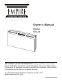 1
1
-
 2
2
-
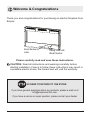 3
3
-
 4
4
-
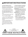 5
5
-
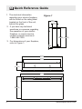 6
6
-
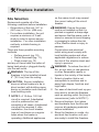 7
7
-
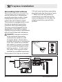 8
8
-
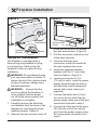 9
9
-
 10
10
-
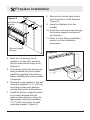 11
11
-
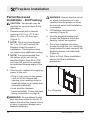 12
12
-
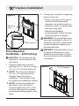 13
13
-
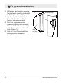 14
14
-
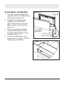 15
15
-
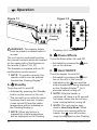 16
16
-
 17
17
-
 18
18
-
 19
19
-
 20
20
-
 21
21
-
 22
22
-
 23
23
-
 24
24
-
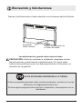 25
25
-
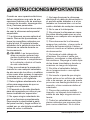 26
26
-
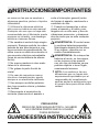 27
27
-
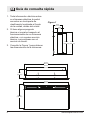 28
28
-
 29
29
-
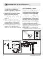 30
30
-
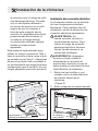 31
31
-
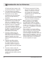 32
32
-
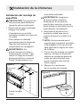 33
33
-
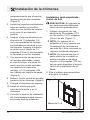 34
34
-
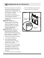 35
35
-
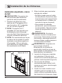 36
36
-
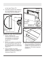 37
37
-
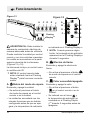 38
38
-
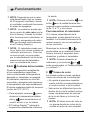 39
39
-
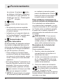 40
40
-
 41
41
-
 42
42
-
 43
43
-
 44
44
-
 45
45


American Hearth EBL34 El manual del propietario
- Categoría
- Chimeneas
- Tipo
- El manual del propietario
- Este manual también es adecuado para
en otros idiomas
- English: American Hearth EBL34 Owner's manual
Artículos relacionados
-
White Mountain Hearth EBL74 El manual del propietario
-
White Mountain Hearth EBL50 El manual del propietario
-
White Mountain Hearth EFRC El manual del propietario
-
-
-
-
-