Impecca ITAC10KS21 Manual de usuario
- Categoría
- Barbacoas
- Tipo
- Manual de usuario
Este manual también es adecuado para

1
Impecca Through-the-Wall
Air Conditioner
Users Manual
ITAC-08KS21
(115V) • ITAC-10KSA21
(115V)
ITAC-12KSA21 (115V) • ITAC-12KSB21 (208/230V)
This manual covers the following models:

Table of Contents:
– Introduction ..................................................................................... p.1
– Safety Notices .................................................................................. p.2-3
– What’s In The Box ................................................................................. p.4
– Operating Your Air Conditioner ................................................................. p.5-7
– Installation Instructions ........................................................................p.8-20
– Care Instructions ................................................................................p.21
– Troubleshooting .............................................................................p.22-23
– Various Machine Sounds/Noises .................................................................p.23
Operating Conditions .............................................................................p.23
– Contact Support ................................................................................p.23
Regulatory Warnings:
DISPOSAL:
Do not dispose this product as unsorted municipal waste. Collection of such waste separately for special
treatment is necessary.
It is prohibited to dispose of this appliance in domestic household waste.
For disposal, there are several possibilities:
A) The municipality has established collection systems, where electronic waste can be disposed of at
least free of charge to the user.
B) When buying a new product, the retailer will take back the old product at least free of charge.
C) The manufacturer will take back the old appliance for disposal at least free of charge to the user.
D) As old products contain valuable resources, they can be sold to scrap metal dealers.
Wild disposal of waste in forests and landscapes endangers your health when hazardous substances leak
into ground-water and nd their way into the food chain.
CAUTION:
• This appliance is not intended for use by persons (including children) with reduced physical, sensory or
mental capabilities, or lack of experience and knowledge, unless they have been given supervision or
instruction concerning use of the appliance by a person responsible for their safety.
• Children should be supervised to ensure that they do not play with the appliance.

1
INTRODUCTION:
Congratulations on your purchase of an IMPECCA™ Electronic Controlled Portable Air Conditioner. Before
using this product, it is recommended that you familiarize yourself with the features, functions, and operat-
ing procedures described in this manual. Inside you will nd many helpful hints on how to use and maintain
your air conditioner properly. Just a little preventive care on your part can save you a great deal of time and
money over the lifespan of your air conditioner. You will nd many answers to common problems in the
chart of troubleshooting tips.
FEATURES AT A GLANCE:
• Quiet Operation
• Energy Saver Function
• Sleep mode
• Remot
e Control with LED
• Eco-Friendly Refrigerant
SAFETY PRECAUTIONS:
To prevent injury and/or property damage, please familiarize yourself with the following instructions
and safety precautions. Failure to comply with the instructions and cautions mentioned in this manual may
cause harm or damage. The seriousness is classied by the following indications:
CAUTION
FOR YOUR SAFETY
• Always contact an authorized service technician for repair or maintenance of this unit.
• Use an authorized and certied technician for installation of this unit.
• This air conditioner is not intended for use by young children or elderly persons without supervision.
• Young children should be supervised to not to operate or play with the air conditioner.
• Power cord replacements should only be performed by certied or authorized technicians.
• All electrical work must be performed in accordance with the national wiring standards and should only
be performed by authorized personnel.
• Before disposing of the device,it is necessary to remove the battery cells and get rid of them safely for
recycling reasons.
• When you need to disposal of the unit consult our dealer. If pipes are removed incorrectly, the refrigerant
may blow out and come into contact with your skin, causing injury. Releasing refrigerant into the atmo-
sphere also damages the environment. Please recycle or dispose of the packaging material for product in
an environmentally responsible manner.
• Never store or ship the air conditioner upside down or sideways to avoid damage to the compressor.
NOTE: Due to slight modications in production, the instructions, features, and/or descriptions found in this
manual might vary slightly from your product.
SAVE TIME AND MONEY!
If you review our chart of Troubleshooting Tips rst, you may not need to call for service at all.
⚠ WARNING This symbol indicates the possibility of serious injury or death.
⚠ CAUTION This symbol indicates the possibility of injury and/or damage to property.
⊘
Never do this.
⍟
Always do this.

2
⍟ Plug in power plug properly.
⊘ Do not operate or stop the unit by insert-
ing or pulling out the power plug.
⊘ Do not damage or use an unspecied
power cord.
• Otherwise, it may cause electric shock or
re due to excess heat generation.
• It may cause electric shock or re due
to heat generation.
• It may cause electric shock or re.
• If the power cord is damaged, it must
be replaced by the manufacturer or an
authorised service centre or a similarly
qualied person to avoid hazard.
⊘ Do not modify power cord length or
share the outlet with other appliances.
⊘ Do not operate with wet hands or
in damp environment.
⊘ Never store air conditioner upside-
down or on its side.
• It may cause electric shock or re due
to heat generation.
• It may cause electric shock. •
⍟ Always ensure eective
grounding/earthing.
⊘ Do not allow water to run
into electric parts.
⍟ Always install circuit breaker and
a dedicated power circuit.
• Incorrect grounding
may cause electric shock.
• It may cause failure of machine
or electric shock.
• Incorrect installation may cause re
and electric shock.
⍟ Unplug the unit if strange sounds, smells,
or smoke comes from it.
⊘ Do not use the socket if it is loose or
damaged.
⊘ Do not open the unit during operation.
• It may cause re and electric shock. • It may cause re and electric shock. • It may cause electric shock.
⍟ Keep rearms away.
⊘ Do not leave the power cord
near heating appliances.
⊘ Do not use the power cord near am-
mable gas or combustibles, such as
gasoline, benzene, thinner, etc.
• It may cause re. • It may cause re and electric shock. • It may cause an explosion or re.
⍟ Ventilate room before operating
air conditioner if there is a gas leakage
from another appliance.
⊘ Do not disassemble or modify unit.
• It may cause explosion, re and, burns. • It may cause failure and electric shock.
WARNING
READ THESE NOTICES CAREFULLY—THEY ARE IMPORTANT!
⊘ When the air lter is to be removed,
do not touch the metal parts of the unit.
⊘ Do not clean the air conditioner
with water.
⍟ Ventilate the room well when used
together with a stove, etc.
• It may cause an injury.
• Water may enter the unit and degrade the
insulation. It may cause an electric shock.
• An oxygen shortage may occur.
⍟ When the unit is to be cleaned, switch o,
and turn o the circuit breaker.
⍟ Do not put a pet or house plant where it
will be exposed to direct air ow.
⊘ Do not use for special purposes.
• Do not clean unit when power is on as it
may cause re and electric shock, it may
cause an injury.
• This could injure or be harmful
to your pet or plants.
• Do not use this air conditioner to pre-
serve precision devices, food, pets,
plants, and art objects.
• It may cause deterioration, etc.
CAUTION
Will cause problems with compressor
and may lead to permanent damage.

3
CAUTION
ELECTRICAL INFORMATION
• Be sure your electrical wiring is adequate for the model
you have chosen. This information can be found on the
serial plate, which is located on the side of the cabinet and
behind the grille.
• Be sure the air conditioner is properly grounded. To min-
imize shock and re hazards, proper grounding is important. The
power cord is equipped with a three-prong grounding plug for
protection against shock hazards.
• Your air conditioner must be connected to a properly grounded
wall receptacle. If the wall receptacle you intend to use is not ade-
quately grounded or protected by a time delay fuse or circuit break-
er, have a qualied electrician install the proper receptacle.
• Ensure the receptacle is accessible after the unit installation.
⍟ Stop operation and close the window
in storm or hurricane.
⍟ Hold the plug by the head of the power
plug when unplugging unit.
⍟ Turn o the main power switch when
not using the unit for a long time.
• Operation with windows opened may
cause wetting of indoor and soaking of
household furniture.
• Otherwise, it may cause electric shock
and damage.
• It may cause failure of product or re.
⊘ Do not place obstacles around air-inlets
or inside of air-outlet.
⊘ Ensure that the installation bracket of the
outdoor appliance is not damaged due to
prolonged exposure.
⍟ Always insert the lters securely.
Clean lter once every two weeks.
• It may cause failure of appliance
or accident.
• If bracket is damaged, the unit can fall and
cause damage, injury or bodily harm.
• Operation without lters may cause
failure.
⊘ Do not use strong detergent such as
wax or thinner to clean the unit.
Use a soft cloth.
⊘ Do not place heavy object on the
power cord and ensure that the cord
is not compressed.
⊘ Do not drink water drained from
air conditioner.
• Appearance may be deteriorated due to
change of product color or scratching of
its surface.
• There is danger of re or electric shock.
• It contains contaminants and could
make you sick.
⍟ Use caution when unpacking and
installing. Sharp edges can cause injury.
⍟ If water enters the unit, turn the unit o at
the power outlet and switch o the circuit
breaker. Isolate supply by taking the pow-
er-plug out and contact a qualied service
technician immediately.
CAUTION
NOTE: The power supply cord with this air conditioner con-
tains a current detection device designed to reduce the risk
of re. In the event that the power supply cord is damaged, it
cannot be repaired-it must be replaced with a cord from the
Product Manufacturer.
The power supply cord contains a current device that senses damage to
the power cord. To test your power supply cord do the following:
1. Plug in the Air Conditioner.
2. The power supply cord will have TWO buttons on the plug head. Press the
TEST button, you will notice a click as the RESET button pops out.
3. Press the RESET button, you will notice a click as the button engages.
4. The power supply cord is now supplying electricity to the unit.
(On some models this it also indicated by a light on the plug head.)
NOTES: • Do not use this device to turn the unit on or o.
• Always make sure the RESET button is pushed in for correct operation.
• The power supply must be replaced if it fails reset when either the TEST button is pushed, or it cannot be reset.
• A new power supply can be obtained from the product manufacturer.
• If power supply cord is damaged, it cannot be repaired. It MUST be replaced by one from the product manufacturer.

4
WHAT’S IN THE BOX:
Please verify your box for the following items. Note that some models may not include all items.
1. Air Conditioning Unit
2. Remote control (may dier from photo)
3. User’s Guide
4. Remote control user’s guide
5. Installation kit (see details below)
❸&
❹
❷
INSTALLATION ACCESSORY KIT ITEMS:
TOOLS REQUIRED: large at blade screwdriver, tape measure, adjustable wrench or pliers, pencil, level,
socket wrenches, and Phillips screwdriver.
NOTE: You may not need all listed parts. Discard unused parts.
PART DESCRIPTION QUANTITY PART DESCRIPTION: QUANTITY:
17” Tapered
Spacer Blocks
2
Trim Frame
(Side Legs)
2
4½” x 3½” x 1½”
Centered/Support Blocks
4
Trim Frame
(Top & Bottom Legs)
2
⅛
” x 4½” x14”
Plastic Divider
1 Ground Wire (green) 1
1”x1½”x25” Seal 3
Toothed Washer
for grounding screw
2
1”x1½”x14” Seal 2 Grounding Screw 1
1”x⅜”x25” Seal 3 Grille (plastic & aluminum) 1
1”x⅜”x14” Seal 2 Nuts (plastic) 4
1”x¾”14” Seal 2 Screw Washer & Screw 4
Avoid damaging your new appliance! If required accessories are missing, please contact technical support
.
Illustrations may vary slightly from actual appearance of parts or product.
❶
1”x1 ½” x 88” Stuffer Seal
1

5
TURNING THE UNIT ON OR OFF:
• Press the On/O Button.
ADJUSTING THE TEMPERATURE:
• Press the up arrow to raise the temperature.
• Press the down arrow to lower the temperature.
• A range of 62°F to 86°F will be maintained.
• To display actual room temperature, use FAN mode.
ADJUSTING THE FAN SPEED:
• Use this button to select fan speed.
• Choose between AUTO, LOW, MED, & HIGH.
• The fan speed in DRY mode is set to low.
SET AUTO, COOL, DRY OR FAN MODES:
• Use the mode button to cycle between the modes.
• AUTO mode automatically selects operating mode
based on ambient room temperature.
• Fan speed can’t be adjusted in AUTO mode.
OPERATING YOUR AIR CONDITIONER:
Before you begin, thoroughly familiarize yourself with the control panels as shown below and all its func-
tions, then follow the symbol for the functions you desire. The unit can be controlled by the unit control
alone or with the remote.
NOTE: This illustration is for explanation purposes only. The actual appearance of the control panel on the
air conditioner you bought may be slightly dierent.

6
FAN ONLY MODE:
• Use this mode when you’d like to circulate air or
exhaust stale air but not run the air conditioner.
• Open the vent in fan mode, but for most eciency
keep it closed during cooling mode.
• The display shows the ambient room temperature.
DRY MODE:
• The unit functions as a dehumidier in dry mode.
• Some cooling may occur during this mode.
ENERGY SAVE FEATURE:
• With a press of the Energy Save button, the fan
continues to blow air through the compressor and
provide cooled air. The fan will run for 2 minutes
every 10 minutes, and cooling will resume once the
room temperature exceeds the set temperature.
SLEEP MODE FEATURE:
• When you push the sleep button, the selected tem-
perature will increase (cooling) or decrease (heat-
ing) by 2°F/1°C after 30 minutes. The temperature
will then increase (cooling) or decrease (heating) by
another 2°f/1°C after an additional 30 minutes.
• The new temperature will be maintained for 7
hours before it returns to the originally selected
temperature. This ends Sleep mode and the unit
will continue to operate as originally programmed.
TIMER & AUTO START/STOP FEATURE:
• The timer indicator lights are for two separate
functions, one to automatically turn the unit on and
another to automatically shut it o. Both programs
can be set at the same time.
Setting the unit to automatically turn o:
• Push the timer button once (if dehumidier is run-
ning) or twice (if dehumidier is not running) until
the ‘OFF’ indicator illuminates
• Use the + and – pad to select the number of hours
before the unit automatically turns o.
• The time will be programmed after 5 seconds of
inactivity and the display will return to show the
humidity level.
Setting the unit to automatically turn on:
• Push the timer button once (if dehumidier is not
running) or twice (if dehumidier is running) until
the ‘ON’ indicator illuminates.
• Use the + and – pad to select the number of hours
before the unit automatically turns o.
• The time will be programmed after 5 seconds of
inactivity and the display will return to show the
humidity level.
NOTE: Both ‘ON’ and ‘OFF’ indicators can be illumi-
nated—the unit will automatically turn itself on and
o according to the programmed times.

7
CHECK FILTER FEATURE:
• The indicator light illuminiates automatically after
250 hours of operation to help you maintain opti-
mum performance.
• To reset after cleaning the lter, press the Check
Filter button and the light will turn o.
DISPLAYS
•
The LED unit displays the set temperature, or in FAN
mode shows the ambient room temperature.
OTHE
R USEFUL NOTES
• The COOL function has an automatic 3 minute time
delayed start if the unit is turned o and on quickly.
This prevents overheating of the compressor and
tripping the circuit breaker. The fan will continue to
run during this time.
• The display unit is capable of displaying tempera-
ture in degrees Fahrenheit or degrees Celsius. To
convert from one to the other, press and hold both
the Up and Down Temp/Timer buttons at the same
time, for 3 seconds.
CHOOSING AIR FLOW DIRECTION
• The 4-way air directional blades allow you to direct
the air ow up or bown (on some models) and left
or right throughout the room as needed. To adjust
the directional blades side-to-side. Use the center
handles as you move it side-to-side.
Move blades up/down or left/right to modify
air ow direction.

8
PREINSTALLATION INSTRUCTIONS:
Please read ALL instructions before installing. We recommend that two people install this product. If a
new electrical outlet is required, have the outlet installed by a qualified electrician before installing unit.
Step 1) Using the following table, find your wall-sleeve brand of your installation. If you cannot find
your your brand of sleeve listed in the table below, you can use whichever one is close in size and
configuration as a guide. There are two important guidelines to keep in mind:
A) The unit itself should be sloped somewhat toward the rear within the sleeve.
B)
The unit should not rest flush with the bottom of a sleeve. Always use the 17" Tapered Spacer Blocks.
C) The unit should always have a sleeve. If you do not already own one, an Impecca Universal Sleeve
Model # ITA-US10 is available from www.impecca.com or your local dealer.
Brand
Dimensions
W x H
x D
Page Brand
Dimensions
W x H
x D
Page
White-Westinghouse
Frigidaire
Carrier (52F Series)
25½” x 15¼” x
16” OR 17½”
OR 22”
17
Sears/Kenmore
Carrier(51S Series)
25¾“ x 16⅞“
x 18⅝“
14
General Electric
Hotpoint
26” x 15⅝”
x 15⅞
14
Fedders
Emerson
26¾”’ x 15¾”
x 15”
10
Whirlpool
25⅞” x 16½”
x17⅛“
15
Fedders, Emerson
Friedrich
27 x 16¾”
x 16¾”
12
Whirlpool
25⅞” x 16½”
x23”
16
Fedders
Emerson
27” x 16¾”
x19¾”
11
NOTE: All wall sleeves used to mount the new air conditioner must be in
sound structural condition and have a rear grille that securely attaches to
sleeve, or rear ange that serves as a stop for the air conditioner.
CAUTION: When installation is complete, replacement unit MUST have a
rearward slope as shown.
Step 2) Remove old air conditioner from wall sleeve and prepare wall sleeve as follows:
• Clean interior (do not disturb seals).
• Wall sleeve must be securely fastened in wall before installing air conditioner.
• Drive more nails or screws through sleeve, into wall, if needed.
• Repair paint if needed.
Step 3) Remove old air conditioner from wall sleeve and prepare wall sleeve as follows:
If a grounding wire is not already place, drill a 1/8 clearance hole for the grounding screw through left side
of wall sleeve, in a clear area about 3 inches maximum back from front edge of sleeve, using the grounding
screw and toothed washer.
Pull loose end of ground wire out front of sleeve, and temporarily bend it down and around lower edge of
sleeve. This ground wire will later be attached to frame of air conditioner once it is installed.
Step 4) Begin specic wall sleeve preparations based on the instructions referenced in the above table.

9
11
This units increased performance characteristics result from having two rear air intakes.
It is very important that these installation instructions are followed so your unit can operate at
maximum efficiency.
If this is an existing sleeve, and there is an existing rear grille, it needs to be replaced by one that
has been shipped with the unit in the accessory kit.
FOR INCREASED EFFICIENCY,UTILIZE THE PROVIDED LOUVERED REAR PANEL
Installation of new grille provided with unit
1. Remove the existing grille.
2. Place the grille included with the new air conditioner towards the rear of the sleeve.
3. Mark through the hole positions.
4. Drill through the sleeves flanges with a 1/8 drill bit.
5. Attached the new grille with self-threading screws and washers.
6. It is VERY IMPORTANT that the grill e is placed exactly as shown below.
7.Most decorative exterior grilles may be left in place as long as the proper interior air direction grille
is installed.
IMPORTANT
READ CAREFULLY—IMPORTANT

10
12
Wall Sleeve Brands:
#1 Emerson 15 Deep
1. Remove existing rear grille as shown on Page
11 of this manual and replace with provided
louvered rear panel. Install as shown here.
NOTE: You may need to drill holes in flange of
existing sleeve to match new rear grille.
2. Attach(1)1 x3/8 x25 long seal in the center at
the top of the sleeve. Remove the backing paper
and press into position.
3. Attach the (2) 1 x3/8 x14 long seals to the
left and right sides of the sleeve.
4. Cut (2) 1 x3/8 x25 long seals to 14 long,and
attach it to the vertical sections of the rear grille
as shown.
5. Attach (2)4 x3 x1 centering/support blocks
one on each side wall. Place in center of side
wall with the tapered end facing the opening.
6. Gently slide unit into sleeve.
7. Before sliding all-the-way back, remove 2nd
screw from front on left side of unit.
8. Remove the plastic washer from the screw.
9. Screw and attach the other end of the ground
wire to the unit as shown in picture. Make sure
that the toothed washer is against the cabinet.
10.Slide the unit completely to the rear to ensure
a good seal, making sure the ground wire does
not become tangled.
11.Seal & Frame the unit as described on page 22.
12. If you have difficulty with mounting the grill to
the sleeve, follow the instructions for direct
mounting on Page 21.
1
/
2
1
/
2
1
/
2
2
4 4
4
4
3
8
3
8
N° 1: EMERSON 15” DEEP WALL SLEEVES
1. Remove existing rear grille as shown on page 9 of this
manual and replace with provided louvered rear panel.
Install as shown here.
11. Seal & frame the unit as described on p.20.
12. If you have diculty with mounting the grill to the
sleeve, follow the instructions for direct mounting on p.19

11
13
Wall Sleeve Brands:
#2 Fedders 19 Deep
1.
3
4
/
2. Attach(2)4 x3 x1 centering/support blocks
one on each side wall. Place in center of side
wall with the tapered end facing the opening.
3. Cut (2) 17 Tapered Spacer Blocks as shown
below into two pieces.
4. The 4 section is placed in front of the rib on
base with the tapered end facing the back of
the sleeve. The remaining portion will be
placed behind the rib again sloping toward
the rear of the sleeve. This helps induce a
rearward slope on the unit.
5. Attach (1)1 x3/8 x25 long seal in the center
at the top of the sleeve. Remove the backing
paper and press into position.
6. Attach (2) 1 x3/8 x14 seals to the left and
right sides of the sleeve.
7. Cut (2) 1 x3/8 x25 long seals to 14 long
and attach it to the vertical sections of the rear
grille as shown.
8. Gently slide unit into sleeve.
9. Before sliding all-the-way back, remove 2nd
screw from front on left side of unit.
10. Remove the plastic washer from the screw.
11. Screw and attach the other end of the ground
wire to the unit as shown in picture. Make sure
that the toothed washer is against the cabinet.
12.Slide the unit completely to the rear to ensure
a good seal, making sure the ground wire does
not become tangled.
13.Seal & Frame the unit as described on page 22.
14. If you have difficulty with mounting the grill to
the sleeve, follow the instructions for direct
mounting on Page 21.
1
/
2
1
/
2
/
2
1
/
2
/
2
Cut Here
3
/
4
17
Tapered Spacer Block
1
Protection Paper
Backing
5
4
Remove existing rear grille as shown on Page
11 of this manual and replace with provided
louvered rear panel. Install as shown here.
NOTE: You may need to drill holes in flange
of existing sleeve to match new rear grille.
4
4
4
4
3
8
3
8
N° 2: FEDDERS 19
¾
” DEEP WALL SLEEVES
1. Remove existing rear grille as shown on page 9 of this
manual and replace with provided louvered rear panel.
Install as shown here.
13. Seal & frame the unit as described on p.20.
14. If you have diculty with mounting the grill to the
sleeve, follow the instructions for direct mounting on p.19

12
14
Wall Sleeve Brands:
#3 Fedders or Friedrich 16 Deep
1.Remove existing rear grille as shown on Page
11 of this manual and replace with provided
louvered rear panel. Install as shown here.
NOTE: You may need to drill holes in flange of
existing sleeve to match new rear grille.
3
4
/
2. Attach(2)4 x3 x1 centering/support blocks
one on each side wall. Place in center of side
wall with the tapered end facing the opening.
3. Cut (2) 17 Tapered Spacer Blocks as shown
below into three pieces.
4. The 2 section is placed in front of the rib on
base with the tapered end facing the back of
the sleeve. Cut the remaining portion to 12
and placed behind the rib again sloping toward
the rear of the sleeve. This helps induce a
rearward slope on the unit.
5. Attach (1)1 x3/8 x25 long seal in the center
at the top of the sleeve. Remove the backing
paper and press into position.
6. Attach (2) 1 x3/8 x14 seals to the left and
right sides of the sleeve.
7. Cut (2) 1 x3/8 x25 long seals to 14 long
and attach it to the vertical sections of the rear
grille as shown.
8. Gently slide unit into sleeve.
9. Before sliding all-the-way back, remove 2nd
screw from front on left side of unit.
10. Remove the plastic washer from the screw.
11. Screw and attach the other end of the ground
wire to the unit as shown in picture. Make sure
that the toothed washer is against the cabinet.
12.Slide the unit completely to the rear to ensure
a good seal, making sure the ground wire does
not become tangled.
13.Seal & Frame the unit as described on page 22.
14. If you have difficulty with mounting the grill to
the sleeve, follow the instructions for direct
mounting on Page 21.
1
/
2
1
/
2
/
2
1
/
2
/
2
Cut Here
3
/
4
17
Tapered Spacer Block
1
Protection Paper
Backing
12-1/2
2-1/2
1
/
2
1
/
2
5
4 4
4
4
3
8
3
8
N° 3: FEDDERS/FRIEDRICH 16
¾”
DEEP WALL SLEEVES
1. Remove existing rear grille as shown on page 9 of this
manual and replace with provided louvered rear panel.
Install as shown here.
13. Seal & frame the unit as described on p.20.
14. If you have diculty with mounting the grill to the
sleeve, follow the instructions for direct mounting on p.19

13
15
Wall Sleeve Brands:
#4 General Electra/Hotpoint 16 Deep
1. Remove existing rear grille as shown on Page
11 of this manual and replace with provided
louvered rear panel. Install as shown here.
NOTE: You may need to drill holes in flange of
existing sleeve to match new rear grille.
7
8
/
2. Cut (2) 17 Tapered Spacer Blocks as shown
below into two pieces.
3. Install 13 section as shown with the tapered end
from the back of the sleeve. This helps induce a
rearward slop on the unit.
4. Attach (1)1 x3/8 x25 long seal in the center
at the top of the sleeve. Remove the backing
paper and press into position.
5. Attach (2) 1 x3/8 x14 seals to the left and
right sides of the sleeve.
6. Cut (2) 1 x3/8 x25 long seals to 14 long
and attach it to the vertical sections of the rear
grille as shown.
7. Center unit and gently slide unit into sleeve.
8. Before sliding all-the-way back, remove 2nd
screw from front on left side of unit.
9. Remove the plastic washer from the screw.
10. Screw and attach the other end of the ground
wire to the unit as shown in picture. Make sure
that the toothed washer is against the cabinet.
11.Slide the unit completely to the rear to ensure
a good seal, making sure the ground wire does
not become tangled.
12.Seal & Frame the unit as described on page 22.
13. If you have difficulty with mounting the grill to
the sleeve, follow the instructions for direct
mounting on Page 21.
1
/
2
3
/
4
17
Tapered Spacer Block
1
Protection Paper
Backing
Cut Here
13
5
4
4
4
4
4
3
8
3
8
N° 4: GENERAL ELECTRIC/HOTPOINT 16
⅞”
DEEP WALL SLEEVES
1. Remove existing rear grille as shown on page 9 of this
manual and replace with provided louvered rear panel.
Install as shown here.
12. Seal & frame the unit as described on p.20.
13. If you have diculty with mounting the grill to the
sleeve, follow the instructions for direct mounting on p.19

14
16
Wall Sleeve Brands:
#5 Sears or Carrier 51S Series
( 18 Deep)
1. Remove existing rear grille as shown on Page
11 of this manual and replace with provided
louvered rear panel. Install as shown here.
NOTE: You may need to drill holes in flange of
existing sleeve to match new rear grille.
5
8
/
2. Install (2) tapered spacer blocks to the floor of
the sleeve as shown. This helps induce a
rearward slop on the unit.
3. Install as shown with the tapered end from
the back of the sleeve. This helps induce a
rearward slop on the unit.
4. Attach (1)1 x3/8 x25 long seal in the center
at the top of the sleeve. Remove the backing
paper and press into position.
5. Attach (2) 1 x3/8 x14 seals to the left and
right sides of the sleeve.
6. Cut (2) 1 x3/8 x25 long seals to 14 long
and attach it to the vertical sections of the rear
grille as shown.
7. Center unit and gently slide unit into sleeve.
8. Before sliding all-the-way back, remove 2nd
screw from front on left side of unit.
9. Remove the plastic washer from the screw.
10. Screw and attach the other end of the ground
wire to the unit as shown in picture. Make sure
that the toothed washer is against the cabinet.
11.Slide the unit completely to the rear to ensure
a good seal, making sure the ground wire does
not become tangled.
12.Seal & Frame the unit as described on page 22.
13. If you have difficulty with mounting the grill to
the sleeve, follow the instructions for direct
mounting on Page 21.
1
/
2
5
4
4
4
4
4
3
8
3
8
N° 5: SEARSKENMORE/CARRIER 51S 18
⅝”
DEEP WALL SLEEVES
1. Remove existing rear grille as shown on page 9 of this
manual and replace with provided louvered rear panel.
Install as shown here.
12. Seal & frame the unit as described on p.20.
13. If you have diculty with mounting the grill to the
sleeve, follow the instructions for direct mounting on p.19

15
17
Wall Sleeve Brands:
#6 Whirlpool 17 Deep
1. Remove existing rear grille as shown on Page
11 of this manual and replace with provided
louvered rear panel. Install as shown here.
NOTE: You may need to drill holes in flange of
existing sleeve to match new rear grille.
1
8
/
2. Cut (2) 17 Tapered Spacer Blocks as shown
below into two pieces.
3. Install 13 section to the floor of the sleeve as
shown. This helps induce a rearward slop on the
unit.
4. Attach (1)1 x3/8 x25 long seal in the center
at the top of the sleeve. Remove the backing
paper and press into position.
5. Attach (2) 1 x3/8 x14 seals to the left and
right sides of the sleeve.
6. Cut (2) 1 x3/8 x25 long seals to 14 long
and attach it to the vertical sections of the rear
grille as shown.
7. Center unit and gently slide unit into sleeve.
8. Before sliding all-the-way back, remove 2nd
screw from front on left side of unit.
9. Remove the plastic washer from the screw.
10. Screw and attach the other end of the ground
wire to the unit as shown in picture. Make sure
that the toothed washer is against the cabinet.
11.Slide the unit completely to the rear to ensure
a good seal, making sure the ground wire does
not become tangled.
12.Seal & Frame the unit as described on page 22.
13. If you have difficulty with mounting the grill to
the sleeve, follow the instructions for direct
mounting on Page 21.
3
/
4
17
Tapered Spacer Block
1
Protection Paper
Backing
Cut Here
13
5
4
4
4
4
4
3
8
3
8
N° 6: WHIRLPOOL 17
⅛”
DEEP WALL SLEEVES
1. Remove existing rear grille as shown on page 9 of this
manual and replace with provided louvered rear panel.
Install as shown here.
12. Seal & frame the unit as described on p.20.
13. If you have diculty with mounting the grill to the
sleeve, follow the instructions for direct mounting on p.19

16
18
Wall Sleeve Brands:
#7 Whirlpool ( 23 Deep)
1. Remove existing rear grille as shown on Page
11 of this manual and replace with provided
louvered rear panel. Install as shown here.
NOTE: You may need to drill holes in flange of
existing sleeve to match new rear grille.
2. Place (2) 1 x1 x14 seals against each side.
3. Gently slide unit in and check if amount extend-
ing from the sleeve is sufficient once the trim
frame is attached.
4. If position is Ok, remove unit and proceed to
the next step. If not go to step 9.
5. Attach (1)1 x1 x25 long seal in the center
at the top of the sleeve. Remove the backing
paper and press into position.
6. Attach (2) 1 x1 x14 seals to the left and
right sides of the sleeve.
7. Cut (2) 1 x x25 long seals to 14 long
and attach to the vertical sections of the grille as
shown.
8. Attach the tapered spacer blocks to the floor of
the sleeve. Now go to step 15.
Use these next steps if the unit requires extra
extension into the room.
9. Attach 1 x x14 long seal over the solid
vertical portion of the rear grille.
10. Attach (2) 4 x3 x1 foam blocks with the
slot overlapping the seal above.
11. Install the divider into the slots of the foam
blocks. You may need to trim the length to size.
12. Repeat steps 9-11 for the other vertical shown
portion of the grille as shown in the picture.
13. Attach (2) 1 x1 x14 seals along the sides
of the sleeve again making sure all seals are
flush.
14.Cut the 1 x1 x25 seal to fit the top of the
sleeve. The pieces must be fitted flush to the
edge of the divider.
15. Center unit and gently slide unit into sleeve.
16. Before sliding all-the-way back, remove 1st
screw from front on left side of unit.
17. Remove the plastic washer from the screw.
18. Screw and attach the other end of the ground
wire to the unit as shown in picture. Make sure
that the toothed washer is against the cabinet.
19.Slide the unit completely to the rear to ensure
a good seal, making sure the ground wire does
not become tangled.
20.Seal & Frame the unit as described on page 22.
21. If you have difficulty with mounting the grill to
the sleeve, follow the instructions for direct
mounting on Page 21.
Because of the increased unit depth, first try
dry fitting using the method described below:
1
/
2
1
/
2
1
/
2
3
/
8
3
/
4
3
/
4
3
/
4
3
/
4
1
/
2
6
5
12
9
11
13
10
14
1
/
2
7
4
4
4
4
3
8
3
8
4
4
7
N° 7: WHIRLPOOL 23
”
DEEP WALL SLEEVES
1. Remove existing rear grille as shown on page 9 of this
manual and replace with provided louvered rear panel.
Install as shown here.
20. Seal & frame the unit as described on p.20.
21. If you have diculty with mounting the grill to the
sleeve, follow the instructions for direct mounting on p.19

17
N° 8: WESTINGHOUSE/CARRIER 52F 16 & 17
”
DEEP WALL SLEEVES
19
Wall Sleeve Brands:
#8 White Westinghouse/Frigidaire/
Carrier 52F Series ( 16 +17 Deep)
1.Remove existing rear grille as shown on Page
11 of this manual and replace with provided
louvered rear panel. Install as shown here.
NOTE: You may need to drill holes in flange of
existing sleeve to match new rear grille.
2. Attach (1)1 x3/8 x25 long seal in the center
at the top of the sleeve. Remove the backing
paper and press into position.
3. Attach (2) 1 x3/8 x14 seals to the left and
right sides of the sleeve.
4. Attach (2) 1 x3/4 x14 long seals vertically 4.5
from the left side of the sleeve .Attach the other
1 x3/4 x14 long seal 4 from the right side of the
sleeve.
5. Center unit and gently slide unit into sleeve.
6. Before sliding all-the-way back, remove 2nd
screw from front on left side of unit.
7. Remove the plastic washer from the screw.
8. Screw and attach the other end of the ground
wire to the unit as shown in picture. Make sure
that the toothed washer is against the cabinet.
9. Slide the unit completely to the rear to ensure
a good seal, making sure the ground wire does
not become tangled.
10.Seal & Frame the unit as described on page 22.
11. If you have difficulty with mounting the grill to
the sleeve, follow the instructions for direct
mounting on Page 21.
1
/
2
4
2
3
4
4
4
4
3
8
3
8
1. Remove existing rear grille as shown on page 9 of this
manual and replace with provided louvered rear panel.
Install as shown here.
10. Seal & frame the unit as described on p.20.
11. If you have diculty with mounting the grill to the
sleeve, follow the instructions for direct mounting on p.19

18
Wall Sleeve Brands:
#9 White Westinghouse or Frigidaire
( 22 Deep)
2. Place (2) 1 x1 x14 seals against each side.
3. Gently slide unit in and check if amount extend-
ing from the sleeve is sufficient once the trim
frame is attached.
4. If position is Ok, remove unit and proceed to
the next step. If not go to step 8.
5. Attach (1)1 x1 x15 long seal to the left and
right sides of the sleeve.
6. Cut (1) 1 x1 x25 long seal to 14 long and
attach it vertically to the rear grill 4.5 from
the left side ,repeat and attach 4 from the right
side.
7. Attach(1) 1 x1 x25 long seal in the center at
the top of the sleeve.Remove the backing paper
and press into position.Proceed to step 14.
Use these next steps if the unit requires extra
extension into the room.
8. Attach 1 x x14 long seal over the solid
vertical portion of the rear grille.
9. Attach (2) 4 x3 x1 foam blocks with the
slot overlapping the seal above.
10. Install the divider into the slots of the foam
blocks. You may need to trim the length to size.
11. Repeat steps 8-10 for the other vertical shown
portion of the grille as shown in the picture.
12. Attach (2) 1 x1 x14 seals along the sides
of the sleeve again making sure all seals are
flush.
13.Cut the 1 x1 x25 seal to fit the top of the
sleeve. The pieces must be fitted flush to the
edge of the divider.
14. Center unit and gently slide unit into sleeve.
15. Before sliding all-the-way back, remove 1st
screw from front on left side of unit.
16. Remove the plastic washer from the screw.
17. Screw and attach the other end of the ground
wire to the unit as shown in picture. Make sure
that the toothed washer is against the cabinet.
18.Slide the unit completely to the rear to ensure
a good seal, making sure the ground wire does
not become tangled.
19.Seal & Frame the unit as described on page 22.
20. If you have difficulty with mounting the grill to
the sleeve, follow the instructions for direct
mounting on Page 21.
Because of the increased unit depth, first try
dry fitting using the method described below:
1
/
2
1
/
2
1
/
2
1
/
2
3
/
4
3
/
4
3
/
4
3
/
4
1
/
2
1
/
2
1.
6
7
11
8
10
12
9
13
Remove existing rear grille as shown on Page
11 of this manual and replace with provided
louvered rear panel. Install as shown here.
NOTE: You may need to drill holes in flange
of existing sleeve to match new rear grille.
5
6
4
4
4
4
3
8
3
8
4
4
N° 9: WHITE/WESTINGHOUSE FRIGIDAIRE 22
”
DEEP WALL SLEEVES
1. Remove existing rear grille as shown on page 9 of this
manual and replace with provided louvered rear panel.
Install as shown here.
19. Seal & frame the unit as described on p.20.
20. If you have diculty with mounting the grill to the
sleeve, follow the instructions for direct mounting on p.19

19
1. Attach the 2 seal pieces (1 X3/8 X14 ) as shown in Fig. 1.
2.Position the grille over the rear of the unit making sure that:
a. The double set of screw holes are at the bottom.
b. The fins of the grill are pointed away from the unit.
3. Align the top of the grille with the top of the unit. The overhang on each side is equal.
4. If the unit has not been pre-drilled (some models), carefully drill 4-1/8 holes through the
grille and into the side flange of the unit approximately 1 to 2 from the top and bottom as
in Fig. 2, 3 .
(Be careful not to drill into the copper heat exchanger coils.)
5. Install 4 - #8 self tapping screws to affix the grille to the unit.
6. Insert the unit into the sleeve.
21
1
/
2
DIRECT MOUNTING INSTRUCTIONS:
The previous directions are the preferable way to mount the new rear grill. The unit’s performance is
slightly better and the possibility of drafts is reduced. As a last resort, direct mounting of the grille to the
unit can be considered.
Note: The grille must be installed prior to inserting the unit into the sleeve.

20
FINISHING INSTALLATION:
1. Install the 1 x1 x84 long stuffer-seal between
the wall-sleeve and the unit. A flat-bladed
screwdriver or putty knife is recommended.
1
/
2
2. Assemble the trim frame by inserting top and
bottom pieces into side pieces and snapping
into place.
3. Pull cord through trim frame then slide over
unit until flush with wall.
22
seAlInG InsTRUCTIons:

21
CARE & CLEANING:
CARE AND CLEANING
Clean your air conditioner occasionally to keep it looking new. Be sure to unplug the unit
before cleaning to prevent chock or fire hazards.
CAUTION
Air Filter Cleaning
The air filter should be checked at least once a
month to see if cleaning is necessary. Trapped
particles in the filter can build up and cause an
accumulation of frost on the cooling coils.
Open the front panel.
Grasp the filter, pull up and out.
Wash the filter using liquid dishwashing deter-
gent and warm water. Rinse filter thoroughly.
Gently shake excess water from the filter. Be
sure the filter is thoroughly dry before replacing.
Or, instead of washing you may vacuum the filter.
Cabinet Cleaning
Be sure to unplug the air conditioner to prevent
shock or fire hazard. The cabinet and front may
be dusted with an oil-free cloth or washed with
a cloth dampened in a solution of warm water
and mild liquid dishwashing detergent. Rinse
thoroughly and wipe dry.
Never use harsh cleaners, wax or polish on the
cabinet front.
Be sure to wring excess water from the cloth before
wiping around the controls. Excess water in or around
the controls may cause damage to the air conditioner.
Plug in air conditioner.
If you plan to store the air conditioner during the winter,
remove it carefully from the window according to the
installation instructions. Cover it with plastic or return it
to the original carton.
Winter Storage
18
Clean your air conditioner occasionally to keep it looking new.
Be sure to unplug the unit before cleaning to prevent shock or re hazards.
CAUTION
Note:
Never use hot water over 104°F (40°C)
to clean the air filter. Never attempt to operate
the unit without the air filter.

22
TROUBLESHOOTING TIPS:
Before calling for service, review this list. It may save you time and expense. This list includes common
occurrences that are not the result of defective workman-ship or materials in this appliance.
Solution
Air conditioner
does not start
Wall plug disconnected. Push plug firmly into wall outlet.
House fuse blown or circuit breaker tripped. Replace fuse with time delay type or
reset circuit breaker.
Plug Current Device Tripped. Press the RESET button.
TROUBLESHOOTING TIPS
Problem
Air from unit does
not feel cold
enough
Reset to a Lower temperature.
Thermostat set too cold for night-time cooling. To defrost the coil, set to FAN ONLY
mode. Then, set temperature to a Higher setting.
Temperature sensing element touching cold coil, located behind air filter. Straighten
tube away from coil.
Air filter may be dirty. Clean filter. Refer to Care and Cleaning section. To defrost,
set to FAN ONLY mode.
Dirty air filter- air restricted. Clean air filter. Refer to Care and Cleaning section.
Unit recently turned on in hot room. Allow additional time to remove Stored heat from
walls, ceiling, floor and furniture.
Control is OFF. Turn Control ON and set to desired setting.
Air conditioner
cooling, but room
is too warm- ice
forming on cooling
coil behind
decorative front.
Outdoor temperature below 62°F (17°C) defrost the coil, set FAN ONLY mode.
Air conditioner
cooling, but room
is too warm- NO
ice forming on
cooling coil behind
decorative front.
Temperature is set too High, set temperature to a Lower setting.
Air directional louvers positioned improperly. Position louvers for better air distribution.
Front of units is blocked by drapes, blinds, furniture, etc. - restricts air distribution.
Clear blockage in front of unit.
Doors, windows, registers, etc. Open- cold air escapes. Close doors, windows, registers.
Compressor shut-off by changing modes. Wait approximately 3 minutes and listen for
compressor to restart when set in the COOL mode.
Air conditioner turns on
and off rapidly
Noise when unit is
cooling
Water dripping
INSIDE when
unit is cooling.
Improper installation. Tilt air conditioner slightly to the outside to allow water drainage.
Refer to installation instructions - check with installer.
Dirty air filter- air restricted. Clean air filter.
Air movement sound. This is normal . If too loud, set to a slower FAN setting.
Outside temperature extremely hot. Set FAN speed to a Higher setting to bring air past
cooling coils more frequently.
Window vibration - poor installation. Refer to installation instructions or check with installer.
19
SAVE TIME AND MONEY!
If you review our chart of Troubleshooting Tips rst, you may not need to call for service at all.
Room temperature below 62°F (17°C). Cooling may not occur until room
temperature rises above 62°F (17°C).

23
TROUBLESHOOTING TIPS:
Impecca customer support can be contacted in the following methods:
• Online 24/7: www.impeccausa.com
• By phone: +1
8
66-954-4440
CONTACT SUPPORT:
Solution
Problem
Water dripping
OUTSIDE when
unit is cooling.
Unit removing large quantity of moisture from humid room. This is normal during
excessively humid days.
Remote Sensing
Deactivating
Prematurely
(some models)
Remote control not located within range. Place remote control within 20 feet & 180 ,
radius of the front of the unit.
Remote control signal obstructed. Remove obstruction.
Room too cold
Set temperature too low. Increase set temperature.
20
NORMAL SOUNDS
AIR CONDITIONER FEATURES
Sound of Rushing Air
At the front of the unit, you may
hear the sound of rushing air
being moved by the fan
High Pitched Chatter
High efficiency compressors
may have a high pitched chatter
during the cooling cycle.
Gurgle/Hiss
Gurgling or hissing noise may
be heard due to refrigerant
passing through evaporator
during normal operation.
Pinging or Switching
Droplets of water hitting condenser
during normal operation may cause
pinging or switching sounds.
Before you begin, thoroughly familiarize yourself with the control panels as shown below and all
its functions, then follow the symbol for the functions you desire. The unit can be controlled
by the unit control alone or with the remote.
Vibration
Unit may vibrate and make noise
because of poor wall or window
construction or incorrect installation.
ELECTRONIC CONTROL OPERATING INSTRUCTIONS
5
Sleep
Check
Filter
Follow
Me
Auto
On/off
Fan
High
Med
Low
Energy
Saver
on
off
Timer
Auto
Fan
Cool
Dry
M
ode
TEMP/TIMER
TEMP/TIMER
UNIT CONTROL
(Cooling Only Models)
(Reverse cycle Models)
Energy
Saver
Sleep Timer
Temp Temp
Tim
er Check
Filter
Fan Dry High Med
Mode
Timer
Auto Cool On Off
Follow
Me
Auto Low
Fan
On/Off
Energy
Saver
Sleep Timer
Temp Temp
Timer Check
Filter
Fan Dry High Med
Mode
Timer
Auto Cool On Off
Follow
Me
Auto Low
Fan
On/Off
Heat
Clean
Air
Clean
Air
NOTE: This illustration is for explanation purposes only. The actual appearance of the
control panel on the air conditioner you bought may be slightly different.
S
S
Cooling operation
Outdoor temp:
O
18-43 C(T1 Environment)
Indoor temp:
O
17-32 C(T1 Environment)
O
21-52 C(T3 Environment)
O
17-32 C(T3 Environment)
Heating operation
Outdoor temp:
O
-5-24 C(T1 Environment)
Indoor temp:
O
0 -27 C(T1 Environment)
O
-7-24 C(T3 Environment)
O
0-30 C(T3 Environment)
Note: Performance may be reduced outside of these operating temperatures.
NOTE:This air conditioner is designed to be operated under condition as follows:
MACHINE SOUNDS/NOISES:
NORMAL SOUNDS
AIR CONDITIONER FEATURES
Sound of Rushing Air
At the front of the unit, you may
hear the sound of rushing air
being moved by the fan
High Pitched Chatter
High efficiency compressors
may have a high pitched chatter
during the cooling cycle.
Gurgle/Hiss
Gurgling or hissing noise may
be heard due to refrigerant
passing through evaporator
during normal operation.
Pinging or Switching
Droplets of water hitting condenser
during normal operation may cause
pinging or switching sounds.
Before you begin, thoroughly familiarize yourself with the control panels as shown below and all
its functions, then follow the symbol for the functions you desire. The unit can be controlled
by the unit control alone or with the remote.
Vibration
Unit may vibrate and make noise
because of poor wall or window
construction or incorrect installation.
ELECTRONIC CONTROL OPERATING INSTRUCTIONS
5
Sleep
Check
Filter
Follow
Me
Auto
On/off
Fan
High
Med
Low
Energy
Saver
on
off
Timer
Auto
Fan
Cool
Dry
M
ode
TEMP/TIMER
TEMP/TIMER
Heat
UNIT CONTROL
(Cooling Only Models)
(Reverse cycle Models)
Energy
Saver
Sleep Timer
Temp Temp
Timer Check
Filter
Fan Dry High Med
Mode
Timer
Auto Cool On Off
Follow
Me
Auto Low
Fan
On/Off
Energy
Saver
Sleep Timer
Temp Temp
Timer Check
Filter
Fan Dry High Med
Mode
Timer
Auto Cool On Off
Follow
Me
Auto Low
Fan
On/Off
Heat
Clean
Air
Clean
Air
NOTE: This illustration is for explanation purposes only. The actual appearance of the
control panel on the air conditioner you bought may be slightly different.
S
S
Note: Performance may be reduced outside of these operating temperatures.
OPERATING CONDITIONS:
Cooling Operation
Outdoor Temp: 64°F - 110°F (18°C- 43°C)
Indoor Temp: 62°F - 89°F (17°C - 32°C)
© Copyright 2015 Impecca

1
Impecca A través de la
pared Manual de usuarios
de aire acondicionado
ITAC-08KS21
(115V) • ITAC-10KSA21
(115V)
I
TAC-12KSA21 (115V) • ITAC-12KSB21 (208/230V)
Este manual incluye los siguientes modelos

Tabla de contenido:
– introducción .....................................................................................p.1
–
Avisos de Seguridad ............................................................................
p.2-3
–
En la caja.
.......................................................................................
p.4
– Uso del aire acondici onado ........................................................ p.5-7
– Instrucciones de instalación.
........................................................
p.8-20
–
Instrucciones de cuidado ........................................................................
p.21
–
Solució n De Prob lem as..........................................................
.p.22-23
– Varios Máq uina Sonido s /Ruidos................................................. p.23
-Co ndiciones de Opera ció n. .. ... .. .. .... ... .. ... .. .. ... .. .. ... .. .. ... .. ... ... .. .. ... ..p.23
–
Comuníquese con el soporte ....................................................................
p.23
Avisos de Regulación:
ELIMINACIÓN:
No se deshaga de este producto como basura local común. Es necesaria la recolección de esta basura para
un tratamiento especial.
Está prohibido desechar este aparato entre la basura doméstica.
Para su eliminación, existen varias posibilidades:
A) El municipio tiene establecido sistemas de recolección, donde la basura electrónica se puede de-
sechar sin cargo alguno para el usuario.
B) Cuando se compra de un producto nuevo, el minorista puede retirar el producto viejo incluso de
forma gratuita.
C) El fabricante tomará de nuevo el aparato viejo para su eliminación incluso sin cargo alguno para el
usuario.
D) Dado que los productos viejos contienen recursos valiosos, se pueden vender a los recicladores de
metal.
La disposición de los residuos en los bosques y áreas naturales pone en peligro su salud cuando las sustan-
cias peligrosas se ltran en las aguas subterráneas, y llegan a la cadena alimenticia.
PRECAUCIÓN:
• Este aparato no está destinado para ser utilizado por personas (incluidos niños) con disminución en sus
capacidades físicas, sensoriales o mentales; o con falta de experiencia y conocimiento, a menos de que
hayan recibido supervisión o instrucciones relativas al uso del aparato por una persona responsable de su
seguridad.
• Los niños deben ser supervisados para asegurarse de que no jueguen con el aparato.

1
INTRODUCCIÓN:
Felicitaciones por su compra de un Aire Acondicionado Portátil Controlado Electrónicamente Impecca™.
Antes de utilizar este producto, se recomienda que se familiarice con las características, funciones y procedi-
mientos operativos descritos en este manual. En su interior encontrará muchos consejos útiles sobre cómo
utilizar y conservar su aire acondicionado. Un poco de cuidado preventivo de su parte puede ahorrarle mu-
cho tiempo y dinero durante la vida útil de su aire acondicionado. Encontrará muchas respuestas a proble-
mas comunes en la tabla de consejos para la solución de problemas.
AHORRE TIEMPO Y DINERO!
Si primero revisa nuestro cuadro de consejos para solución de problemas, es posible que no necesite
llamar al servicio técnico.
VISTAZO A LAS CARACTERÍSTICAS:
• Funcionamiento silencioso
• Función de Ahorro de Energía
• Modo de suspensión
• C
ontrol Remoto con LED
• Refrigerante Amigable con el Medio Ambiente
MEDIDAS
DE SEGURIDAD:
Para evitar lesiones y / o daños a la propiedad, por favor familiarícese con las siguientes instrucciones
y precauciones de seguridad. El incumplimiento de las instrucciones y precauciones mencionadas en este
manual puede causar lesiones o daños. Su gravedad se clasica mediante las siguientes indicaciones:
⚠
ADVERTENCIA
Este símbolo indica la posibilidad de lesiones graves o la muerte.
⚠
PRECAUCIÓN
Este símbolo indica la posibilidad de lesiones y / o daños a la propiedad.
⊘
Nunca haga esto.
⍟
Siempre haga esto.
IMPORTANTE:
• Siempre contacte a un técnico de servicio autorizado para la reparación o mantenimiento de esta uni-
dad.
• Este aire acondicionado no está diseñado para ser utilizado por niños o adultos mayores sin supervisión.
• Se debe advertir a los niños pequeños sobre no utilizar el aire acondicionado.
• Si el cable de alimentación debe ser sustituido, el trabajo de sustitución sólo debe ser realizado por técni-
cos certicados o autorizados.
• Todos los trabajos eléctricos deben ser realizados de acuerdo con las normas nacionales de cableado y
sólo debe ser realizado por personal autorizado.
NOTA: Debido a ligeras modicaciones en la producción, las instrucciones, características y / o descripciones
que se encuentran en este manual pueden variar ligeramente a las de su producto.

2
⍟ Conecte el enchufe de forma adecuada.
⊘ No prenda y apague esta unidad al conec-
tar y desconectar el enchufe.
⊘ No dañe ni utilice un cable de alimenta-
ción no especicado.
• De no hacerlo puede causar una descarga
eléctrica o fuego debido a la generación
de calor.
• Puede causar una descarga eléctrica o
fuego debido a la generación de calor.
• Puede causar una descarga eléctrica.
• Si el cable de alimentación está daña-
do, debe reemplazase por el fabricante
en un centro de servicio autorizado o
por una persona similar calicada, para
evitar daños.
⊘ No modique la longitud del cable ali-
mentación o comparta el tomacorriente
con otros aparatos.
⊘ No opere el aparato con las manos moja-
das o en ambientes húmedos.
⊘ No dirija el ujo de aire directamente
sobre los ocupantes de la habitación.
• Puede causar una descarga eléctrica o
fuego debido a la generación de calor.
• Puede causar una descarga. • Esto puede ser perjudicial para la salud.
⍟ Asegúrese que siempre exista la adecuada
conexión a tierra en el tomacorriente.
⊘ No permita que el agua caiga sobre las
partes eléctricas.
⍟ Instale siempre un interruptor de
circuito y un circuito de alimentación
dedicados.
• Una conexión incorrecta a tierra puede
causar una descarga.
• Esto puede causar fallas en la unidad o
descarga eléctrica.
• Una incorrecta instalación puede cau-
sar fuego y descarga eléctrica.
⍟ Desconecte la unidad si nota ruidos ex-
traños, olor o humo proveniente de ella.
⊘ No utilice la unidad si el enchufe está ojo
o dañado.
⊘ No abra la unidad si esta está en funcio-
namiento.
• Puede causar una descarga eléctrica y/o
fuego.
• Puede causar una descarga eléctrica y/o
fuego.
• Puede causar una descarga eléctrica.
⍟ Mantenga las armas de fuego lejos.
⊘ No utilice el cable de alimentación cerca de
aparatos que generan calor.
⊘ No utilice el cable de alimentación cerca
de gas inamable o combustibles como
benceno, thinner o gasolina, etc.
• Puede causar fuego.
• Puede causar una descarga eléctrica y/o
fuego.
• Puede ocurrir un incendio y/o explo-
sión.
⍟ Ventile la habitación antes de poner a fun-
cionar el aire acondicionado si ha habido
una fuga de gas de otro aparato.
⊘ No desarme o modique la unidad.
Puede ocurrir un incendio y/o explosión y
quemaduras.
• Puede causar fallas y descarga eléctrica.
ADVERTENCIA
LEA CUIDADOSAMENTE ESTOS AVISOS—SON IMPORTANTES!
⊘ Cuando deba retirar el ltro de aire, no
toque las partes metálicas de la unidad.
⊘ No limpie el aire acondicionado con agua.
⍟ Ventile bien la habitación cuando se
utilice cerca de una estufa, etc.
• Puede ocurrir una lesión.
• El agua puede entrar en la unidad y dis-
minuir el aislamiento. Puede ocurrir una
descarga eléctrica.
• Puede provocar una falta de oxígeno.
⍟ Cuando la unidad deba limpiarse, apáguela
y desconéctela o cierre el interruptor de
circuito.
⍟ No ponga una planta o a una mascota en
donde estén expuestos al ujo directo del
aire.
⊘ No se utilice para propósitos especia-
les.
• No limpe la unidad cuando está encen-
dida, puede causar fuego o descarga
eléctrica, así como lesiones.
• Esto puede lastimar o ser peligroso para
las mascotas o plantas.
• No utilice este aire acondicionado
para conservar dispositivos de pre-
cisión, alimentos, mascotas, plantas y
objetos de arte.
• Pueden deteriorarse, etc.
PRECAUCIONES

3
PRECAUCIONES
INFORMACION ELECTRICA
• Asegúrese que el servicio eléctrico es el adecuado para el modelo
que ha elegido. Esta información puede encontrarse en la placa del
número de serie que está colocada a un costado del gabinete detrás
de la rejilla.
• Asegúrese que el aire acondicionado esté debidamente aterrizado.
Para minimizar el peligro de incendio y de descarga, es importante contar con una
tierra adecuada. El cable de alimentación está equipado con un enchufe aterrizado
de 3 patas como protección en contra de posibles descargas eléctricas.
• Su aire acondicionado debe ser utilizado en un tomacorriente debidamente aterriza-
do. Si el tomacorriente que pretende usar no cuenta con la tierra adecuada o no está
protegido con un fusible de demora de tiempo o un interruptor de circuito haga que
un electricista calicado instale un tomacorriente adecuado.
• Asegúrese que el tomacorriente esté accesible antes de instalar la unidad.
⍟ Detenga la operación y cierre la ventana en
caso de huracán o tormenta.
⍟ Sostenga rmemente el enchufe del cable
de alimentación cuando desconecte la
unidad.
⍟ Mantenga el interruptor de energía
principal apagado cuando no utilice la
unidad por largos periodos de tiempo.
• La operación con las ventanas abiertas
puede causar que el interior se anegue y
se mojen los muebles de la habitación.
• De no hacerlo puede causar daños y des-
carga eléctrica.
• Puede causar fallas del producto o
fuego.
⊘ No coloque obstáculos alrededor de las
entradas de aire o dentro de las salidas de
aire.
⊘ Asegúrese que el soporte de instalación
no esté dañado debido a una prolongada
exposición a los elementos externos.
⍟ Siempre coloque adecuadamente los
ltros.
Límpielos una vez cada 2 semanas.
• Esto puede causar fallas en la unidad o
accidentes.
• Si el soporte está dañado la unidad puede
no estar bien sostenida, caer y causar
daños o lesiones corporales.
• La operación sin ltros puede causar
fallas.
⊘ No utilice detergentes fuertes, ceras o
thinner para limpiar. Utilice en su lugar un
paño suave.
⊘ No coloque objetos pesados sobre el cable
de alimentación. Asegure que el cable no
está siendo oprimido.
⊘ No beba el agua que drena del aire
acondicionado
• Puede causar cambios en la apariencia de-
bido al cambio de color o por el deterioro
de la supercie.
• Hay pelifro de incendio o descarga eléc-
trica.
• El agua que sale de la unidad contiene
contaminantes dañinos que pueden
causar enfermedad.
⍟ Tenga cuidado al desempacar e instalar
la unidad. Los bordes alados pueden
causarle daños.
⍟ Si entra agua dentro de la unidad,
apáguela, cierre el interruptor circuito y
desconecte. Aísle la unidad al desconec-
tarla y llame a un técnico calicado se
servicio inmediatamente.
PRECAUCIONES
NOTA: El cable de alimentación de corriente de este aire
acondicionado contiene un dispositivo de detección de corri-
ente para reducir el riesgo de incendio. Para mayor información
reérase a la sección de “Operación del Dispositivo de Corriente”.
En el caso de que el cable de alimentación de corriente esté
dañado este no debe ser reparado. Debe reemplazarse por uno
nuevo.
El cable de alimentación de corriente contiene un dispositivo de detección de corriente
que detecta daños al cable de alimentación. Para probar su cable haga lo siguiente:
1. Conecte el aire acondicionado.
2. En el enchufe del cable de alimentación hay DOS botones. Presione el botón TEST (Prue-
ba), oirá un clic al tiempo que el botón RESET (restablecer) sobresale.
3. Presione el botón RESET (restablecer), de nuevo oirá un clic conforme el botón se mete.
4. Ahora, el cable de alimentación permite el paso de electricidad hacia la unidad.
(En algunos productos esto se indica por una luz en el enchufe.)
NOTAS: • No utilice el dispositivo de corriente para encender o apagar la unidad.
• Para una adecuada operación siempre asegúrese que el botón RESET está oprimido.
• Debe reemplazarse el cable de alimentación cuando falle el RESET (restablecer) al presionar el botón TEST (prueba),
o no puede restablecerse. Obtenga un cable nuevo al llamar al servicio técnico.
• Si el cable de alimentación está dañado, no debe reparase. DEBE ser reemplazado por otro cable que provenga del
fabricante del producto..
Nunca corte, remue-
va, corte o ignore la
pata para tierra.
Cable de alimentación de corriente con
enchufe aterrizado de 3 patas y dispositi-
vo de detección de corriente.
Conecte y
presione
RESET
(Restablecer)

4
❸&
❹
❷
PIEZAS DEL JUEGO PARA INSTALACION:
HERRAMIENTAS REQUERIDAS: desarmador largo de cabeza plana, cinta métrica, llave inglesa o pinzas,
lápiz, nivel, llaves de dados, desarmador Phillips.
DESCRIPCION DE LA PIEZA
CANTIDAD INCLUIDA:
DESCRIPCION DE LA PIEZA
CANTIDAD INCLUIDA:
17” bloques de
separación cónicos
2
Recorte Frame
(Patas laterales)
2
4½” x 3½” x 1½”
Centrado/Soporte
Bloques
4
Recorte Frame
(Patas Arriba y Abajo)
2
⅛” x 4½” x 84”
Separador de plástico
1 Hilo de tierra (verde) 1
1”x1½”x25” Sello 3
Arandela dentada
tornillo de conexión a tierra
2
1”x1½”x14” Sello 2 Conexión a tierra 1
1”x⅜”x25” Sello 3 Rejilla (plástico y aluminio) 1
1”x⅜”x14” Sello 2 Nueces (plástico) 4
1”x¾”14” Sello 2 Tornillo Arandela y tornillo 4
¡Evite dañar su nuevo aparato! Si faltan accesorios necesarios haga contacto con soporte técnico. Las imá-
genes pueden variar ligeramente de aquellas que vienen en su aparato.
❶
QUE VIENE EN LA CAJA:
Verique las siguientes piezas en la caja. Tome en cuenta que algunos modelos pueden no incluir todas las
piezas.
1. Unidad de Aire Acondicionado
2. Control Remoto
(Puede ser un poco diferente al mostrado en la imagen)
3. Manual de Usuario
4. Manual de Usuario del Control Remoto
5. Juego para Instalación (Vea el detalle a continuación)

5
PRENDIENDO Y APAGANDO LA UNIDAD:
• Presione el botón On/O.
AJUSTANDO LA TEMPERATURA:
• Presione la echa que apunta hacia arriba para incrementar la
temperatura.
• Presione la echa que apunta hacia abajo para disminuir la
temperatura.
• Podrá mantener una temperatura en un rango de 62°F a 86°F
(17°C a 30°C).
• Para desplegar la temperatura actual de la habitación utilice el
modo FAN (ventilador).
AJUSTANDO LA VELOCIDAD DEL VENTILADOR:
• Utilice el botón FAN para seleccionar la velocidad del ventilador.
• Elija entre AUTO (automática), LOW (baja), MED (media), & HIGH (alta).
• La velocidad del ventilador en el modo DRY (Secar) se ja en LOW
(baja).
FIJANDO LOS MODOS AUTO
AUTOMÁTICO,
COOL ENFRIAR, DRY SECAR, O FAN
VENTILADOR:
• Utilice el botón MODE (modo) para cambiar los modos de forma
cíclica.
• El modo AUTO (Automático) selecciona el modo de operación en
forma automática basándose en la temperatura ambiente de la
habitación.
• No puede ajustarse la velocidad del ventilador en el modo AUTO.
PONIENDO EN FUNCIONAMIENTO SU AIRE ACONDICIONADO:
Antes de continuar familiarícese ampliamente con el panel de control y sus funciones que se muestran a
continuación, después siga el símbolo para la función deseada. La unidad puede ser controlada mediante el
panel de control al frente de la unidad o por el control remoto.

6
MODO FAN ONLY VENTILADOR:
• Utilice esta función cuando no desee enfriar la habitación sino sola-
mente hacer circular el aire o para sacar el aire viciado.
• Abra el respiradero durante esta función, pero manténgalo cerrado
durante el modo COOL (enfriar) para una mayor eciencia.
• La pantalla mostrará la temperatura ambiente de la habitación.
MODO DRY SECAR:
• En este modo, el aire acondicionado funcionará
como un deshumidicador.
• En este modo puede ocurrir algo de enfriamiento.
FUNCION DE AHORRO DE ENERGIA:
• Cuando se presiona el botón ENERGY SAVE (Ahorro de
Energía) el ventilador continúa soplando aire a través del com-
presor proporcionando aire fío. El ventilador se activara por
2 minutos cada 10 minutos y el enfriamiento continuará una
vez que la temperatura de la habitación exceda la temperatu-
ra que fue especicada.
FUNCIÓN DEL MODO SLEEP ESPERA:
Cuando presiona el botón SLEEP la temperatura seleccionada
se incrementará (en enfriamiento) o disminuirá (en cale-
facción) en 1°C/2°F luego de 30 minutos. La temperatura
después se incrementará (en enfriamiento) o disminuirá (en
calefacción) en otro 1°C/2°F después de otros 30 minutos
adicionales.
• La nueva temperatura se mantendrá por 7 horas antes de
regresar a la temperatura originalmente seleccionada. Esto
terminará con el modo SLEEP (espera) y la unidad continuará
operando como se programó originalmente.
TEMPORIZADOR Y FUNCIONES DE AUTO START/
AUTO STOP INICIO Y PARO AUTOMÁTICOS:
• Las luces indicadoras del temporizador son para dos fun-
ciones por separado, una de ellas enciende la unidad en forma
automática y la otra la apaga también de forma automática.
Ambos programas se pueden jar al mismo tiempo.
Ajuste de la unidad para apagarse de forma automática:
• Presione el botón TIMER una vez (si está funcionando el
deshumidicador) o dos veces (si no está funcionando el
deshumidicador) hasta que se ilumine el indicador ‘OFF’.
• Utilice las teclas + y – para seleccionar el número de horas
para apagar la unidad en forma automática.
• El tiempo será programado después de 5 segundos de inactiv-
idad y la pantalla regresará a mostrar el nivel de humedad.
Ajuste de la unidad para encenderse de forma automática:
• Presione el botón TIMER una vez (si no está funcionando el
deshumidicador) o dos veces (si está funcionando el deshu-
midicador) hasta que se ilumine el indicador ‘ON’.
• Utilice las teclas + y – para seleccionar el número de horas
para que se encienda automáticamente la unidad.
• El tiempo será programado después de 5 segundos de inactiv-
idad y la pantalla regresará a mostrar el nivel de humedad.
NOTA: Ambas luces indicadoras ‘ON’ y ‘OFF’ pueden ilumi-
narse—la unidad se encenderá y apagará automáticamente
de acuerdo a los tiempos programados.
SENSOR REMOTO DE TEMPERATURA PERSONAL:
• NOTA: Esta función SOLO se puede activar desde
el control remoto. El control remoto se convierte
en un termostato remoto permitiendo el control
preciso de temperatura en la ubicación del con-
trol remoto.
• Para activar la función de Sensor Remoto de
Temperatura Personal, apunte el control remo-
to hacia la unidad y presione el botón PMTS. El
control remoto mostrará la temperatura actual en
la ubicación del control remoto. El control remoto
mandará esta señal cada 3 minutos hasta que se
vuelva a presionar el botón PMTS.
• Si la unidad no recibe la señal PMTS después de 7
minutos, la unidad emitirá un sonido que indica
que el modo Sensor Remoto de Temperatura
Personal ha terminado.

7
FUNCION DE REVISION DEL FILTRO:
• Para ayudarle a que conserve un despeño óptimo la
luz indicadora CHECK FILTER se iluminará luego de
250 horas de operación.
• Para restaurar luego de limpiar el ltro presione el
botón Check Filter y la luz se apagará.
PANTALLAS
• La pantalla LCD de la unidad despliega la temperatura asignada o en
el modo FAN (Ventilador) muestra la temperatura ambiente.
FUNCION AIRE LIMPIO CON IONES
•
Se energizará el generador de iones y le ayudará a retirar del aire las
partículas de polen e impurezas QUE PASA A LA UNIDAD.
OTHER USEFUL THINGS
• La función COOL (enfriar) cuenta con un sistema
automático de arranque con un tiempo de retraso
de 3 minutos si la unidad se apaga y se enciende
rápidamente. Esto evita el sobrecalentamiento del
compresor así como un posible disparo del cort-
acorriente. El ventilador continuará funcionando
durante este tiempo.
• La pantalla de la unidad es capaz de mostrar la tem-
peratura en grados Fahrenheit o Centígrados. Para
mostrar uno u otro, presione y sostenga al mismo
tiempo por tres segundos los botones de echa
arriba y echa abajo del Temp/Timer.
CONTROL DE VENTILAS PARA AIRE FRESCO
SOLO CIERTOS MODELOS
Las ventilas de aire fresco permiten que el aire acondicionado:
1. Recircule el aire interior—ventila cerrada (imagen 1)
2. Enviar aire fresco a la habitación —ventilas abierta (imagen
2)
3. Intercambio de aire de la habitación y envío de aire fresco a
la habitación—ventila y escape abiertos (imagen 3)
ELIGIENDO LA DIRECCION DEL FLUJO DE AIRE
• Las hojas direccionales de aire en 4 vías permiten
dirigir el aire hacia arriba o abajo (sólo algunos
modelos) y a la derecha o izquierda según se
necesite. Para ajustar las hojas direccionales a un
lado o a otro utilice las palancas al centro para mov-
erlas de un lado a otro.
Display
Area
Imagen 1:
Ventila Cerrada
Imagen 2:
Ventila Abierta
Imagen 3:
Ventila y Escape
Abiertos
Mueva las hojas hacia arriba o abajo para modi-
car el ujo del aire.

8
INSTRUCCIONES DE INSTALACIÓN PREVIA
Por favor lea TODAS las instrucciones antes de instalar. Se recomiendan dos personas para instalar este
producto. En caso de requerirse un tomacorriente eléctrico nuevo, este debe ser instalado por un electricista
calicado antes de instalar la unidad.
Paso 1) Usando la siguiente tabla, encuentre el soporte de pared para su instalación.
Marca
Dimensiones
Ancho x Alto
x Profundidad
Pági-
na
Marca
Dimensiones
Ancho x Alto
x Profundidad
Pági-
na
White-Westinghouse
Frigidaire
Carrier (Serie 52F)
25½” x 15¼” x
16” O 17½”
O 22”
17
Sears/Kenmore
Carrier(51S Series)
25¾“ x 16⅞“
x 18⅝“
14
General Electric
Hotpoint
26” x 15⅝”
x 15⅞
14
Fedders
Emerson
26¾”’ x 15¾”
x 15”
10
Whirlpool
25⅞” x 16½”
x17⅛“
15
Fedders, Emerson
Friedrich
27 x 16¾”
x 16¾”
12
Whirlpool
25⅞” x 16½”
x23”
16
Fedders
Emerson
27” x 16¾”
x19¾”
11
NOTA: Todos los soportes de pared utilizados para montar nuevo el aire
acondicionado deben tener un estado estructural de sonido, y una rejilla
posterior que mantenga de forma segura el soporte o pestaña trasera que
sirve como tope para el aire acondicionado.
PRECAUCIÓN: Cuando la instalación se haya completado, la unidad de
reemplazo debe tener una inclinación hacia atrás como se muestra.
Paso 2) Retire el aire acondicionado viejo del soporte de pared y prepare el soporte de pared de la siguiente
manera:
• Limpie el interior (no modique los sellos).
• El soporte de pared debe estar bien sujeto a la pared antes de instalar el aire acondicionado.
• Si es necesario, introduzca más clavos o tornillos a través del soporte de pared en la pared.
• Repare la pintura si es necesario.
Paso 3) Retire el aire acondicionado viejo del soporte de pared y prepare el soporte de pared de la siguiente
manera: Si un cable de conexión a tierra aún no está puesto, perfore un agujero de paso de 1/8 para el tor-
nillo de conexión a tierra por el lado izquierdo del soporte de pared, en un área libre de aproximadamente
3 pulgadas como máximo a partir de la parte trasera del borde del soporte de pared, usando el tornillo de
polo a tierra y la arandela dentada.
Hale la terminación del cable de tierra hacia afuera por el frente del soporte de pared, y temporalmente dó-
blelo hacia abajo y alrededor del borde inferior del soporte de pared. Después, este cable de tierra se adjun-
tará al marco del aire acondicionado una vez que esté instalado.
Paso 4) Sea especíco en la adecuación del soporte de pared basándose en las instrucciones a las que se
hace referencia en la tabla anterior.

9
11
This units increased performance characteristics result from having two rear air intakes.
It is very important that these installation instructions are followed so your unit can operate at
maximum efficiency.
If this is an existing sleeve, and there is an existing rear grille, it needs to be replaced by one that
has been shipped with the unit in the accessory kit.
FOR INCREASED EFFICIENCY,UTILIZE THE PROVIDED LOUVERED REAR PANEL
Installation of new grille provided with unit
1. Remove the existing grille.
2. Place the grille included with the new air conditioner towards the rear of the sleeve.
3. Mark through the hole positions.
4. Drill through the sleeves flanges with a 1/8 drill bit.
5. Attached the new grille with self-threading screws and washers.
6. It is VERY IMPORTANT that the grill e is placed exactly as shown below.
7.Most decorative exterior grilles may be left in place as long as the proper interior air direction grille
is installed.
LEA ATENTAMENTE-IMPORTANTE
• Las características del rendimiento incrementado de esta unidad se deben a que cuenta con dos tomas de aire en la parte poste-
rior.
• Es muy importante seguir estas instrucciones de instalación de manera que su unidad opere con una eciencia máxima
• Si se trata de una carcasa ya existente y también cuenta con una rejilla posterior necesita ser reemplazada por la que vino em-
pacada con su unidad.
PARA UNA MAYOR EFICIENCIA UTILICE EL PANEL POSTERIOR CON PERSIANAS QUE SE LE HA PROPORCIONADO.
Instalación de la nueva rejilla que vino con su unidad.
1. Retire la rejilla existente.
2. Coloque en la parte posterior de la carcasa la rejilla nueva que vino con su unidad.
3. Marque las posiciones de los oricios.
4. Perfore a través de los rebordes de la carcasa con una broca de 1/8”.
5. Fije la nueva rejilla con tornillos de auto enroscado y arandelas.
6. Es MUY IMPOTANTE que la parrilla esté colocada como se muestra más adelante.
7. Pueden dejarse en su lugar algunas parrillas decorativas exteriores siempre y cuando se instale la parrilla que
proporciona la dirección de aire adecuada.

10
12
Wall Sleeve Brands:
#1 Emerson 15 Deep
1. Remove existing rear grille as shown on Page
11 of this manual and replace with provided
louvered rear panel. Install as shown here.
NOTE: You may need to drill holes in flange of
existing sleeve to match new rear grille.
2. Attach(1)1 x3/8 x25 long seal in the center at
the top of the sleeve. Remove the backing paper
and press into position.
3. Attach the (2) 1 x3/8 x14 long seals to the
left and right sides of the sleeve.
4. Cut (2) 1 x3/8 x25 long seals to 14 long,and
attach it to the vertical sections of the rear grille
as shown.
5. Attach (2)4 x3 x1 centering/support blocks
one on each side wall. Place in center of side
wall with the tapered end facing the opening.
6. Gently slide unit into sleeve.
7. Before sliding all-the-way back, remove 2nd
screw from front on left side of unit.
8. Remove the plastic washer from the screw.
9. Screw and attach the other end of the ground
wire to the unit as shown in picture. Make sure
that the toothed washer is against the cabinet.
10.Slide the unit completely to the rear to ensure
a good seal, making sure the ground wire does
not become tangled.
11.Seal & Frame the unit as described on page 22.
12. If you have difficulty with mounting the grill to
the sleeve, follow the instructions for direct
mounting on Page 21.
1
/
2
1
/
2
1
/
2
2
4 4
4
4
3
8
3
8
N° 1: SOPORTES DE PARED EMERSON 15”
1. Retire la parrilla posterior existente como se muestra en la pági-
na 9 de este manual y reemplácela con la rejilla de persianas que
vino con su unidad. Instale como se muestra aquí.
NOTA: Tal vez requiera perforar oricios en los rebordes de la
carcasa existente para coincidir con la nueva rejilla.
2. Coloque (1) junta de 1”x3/8”x25” de largo en el centro en la
parte superior de la carcasa. Retire el papel protector y presione
para jar.
3. Coloque (2) juntas de 1”x3/8”x14” de largo a los lados izquierdo
y derecho de la carcasa.
4. Corte (2) juntas de 1”x3/8”x25” de largo a 14” de largo y je en
las secciones verticales de la rejilla como se muestra.
5. Fije (2) bloques de apoyo y centrado de 4 ½”x3 ½” x 1 ½” en
cada una de las paredes laterales. Coloque en el centro de la
pared lateral con el extremo cónico mirando hacia la abertura de
la carcasa.
6. Deslice suavemente la unidad dentro de la carcasa.
7. Antes de deslizar la unidad hasta el fondo retire el segundo
tronillo al frente del lado izquierdo de la unidad.
8. Retire la arandela de plástico del tornillo.
9. Atornille y je a la unidad el extremo suelto del cable para tierra
como se muestra en l la gura.
10. Deslice completamente hasta atrás la unidad para asegurar un
buen sellado, asegurándose que el cable de tierra no se enrede.
11. Selle y enmarque la unidad como se describe en la página 20.
12. Si tiene dicultad al montar la rejilla en la carcasa siga las
instrucciones de montaje directo en la página no. 19.

11
13
Wall Sleeve Brands:
#2 Fedders 19 Deep
1.
3
4
/
2. Attach(2)4 x3 x1 centering/support blocks
one on each side wall. Place in center of side
wall with the tapered end facing the opening.
3. Cut (2) 17 Tapered Spacer Blocks as shown
below into two pieces.
4. The 4 section is placed in front of the rib on
base with the tapered end facing the back of
the sleeve. The remaining portion will be
placed behind the rib again sloping toward
the rear of the sleeve. This helps induce a
rearward slope on the unit.
5. Attach (1)1 x3/8 x25 long seal in the center
at the top of the sleeve. Remove the backing
paper and press into position.
6. Attach (2) 1 x3/8 x14 seals to the left and
right sides of the sleeve.
7. Cut (2) 1 x3/8 x25 long seals to 14 long
and attach it to the vertical sections of the rear
grille as shown.
8. Gently slide unit into sleeve.
9. Before sliding all-the-way back, remove 2nd
screw from front on left side of unit.
10. Remove the plastic washer from the screw.
11. Screw and attach the other end of the ground
wire to the unit as shown in picture. Make sure
that the toothed washer is against the cabinet.
12.Slide the unit completely to the rear to ensure
a good seal, making sure the ground wire does
not become tangled.
13.Seal & Frame the unit as described on page 22.
14. If you have difficulty with mounting the grill to
the sleeve, follow the instructions for direct
mounting on Page 21.
1
/
2
1
/
2
/
2
1
/
2
/
2
Cut Here
3
/
4
17
TaperedSpacer Block
1
Protection Paper
Backing
5
4
Remove existing rear grille as shown on Page
11 of this manual and replace with provided
louvered rear panel. Install as shown here.
NOTE: You may need to drill holes in flange
of existing sleeve to match new rear grille.
4
4
4
4
3
8
3
8
N° 2: SOPORTES DE PARED FEDDERS 19
¾
”
1. Retire la parrilla posterior existente como se muestra en la pági-
na 9 de este manual y reemplácela con la rejilla de persianas que
vino con su unidad. Instale como se muestra aquí.
NOTA: Tal vez requiera perforar oricios en los rebordes de la
carcasa existente para coincidir con la nueva rejilla.
2. Fije (2) bloques de apoyo y centrado de 4 ½”x3 ½” x 1 ½” en
cada una de las paredes laterales. Coloque en el centro de la
pared lateral con el extremo cónico mirando hacia la abertura de
la carcasa.
3. Corte (2) bloques espaciadores cónicos de 17” en dos piezas
como se muestra en la gura.
4. La sección de 4”se coloca al frente de la nervadura en la base
con la parte cónica mirando hacia la parte posterior de la carca-
sa. Esto ayuda a inducir la pequeña inclinación hacia atrás que
requiere la unidad.
5. Coloque (1) junta de 1”x3/8”x25” de largo en el centro en la
parte superior de la carcasa. Retire el papel protector y presione
para jar.
6. Coloque (2) juntas de 1”x3/8”x14” de largo a los lados izquierdo
y derecho de la carcasa.
7. Corte (2) juntas de 1”x3/8”x25” de largo a 14” de largo y je en
las secciones verticales de la rejilla como se muestra.
8. Deslice suavemente la unidad dentro de la carcasa.
9. Antes de deslizar la unidad hasta el fondo retire el segundo
tronillo al frente del lado izquierdo de la unidad.
10. Retire la arandela de plástico del tornillo.
11. Atornille y je a la unidad el extremo suelto del cable para
tierra como se muestra en l la gura. Asegure que la arandela con
dientes este contra el gabinete.
12. Deslice completamente hasta atrás la unidad para asegurar un
buen sellado, asegurándose que el cable de tierra no se enrede.
13. Selle y enmarque la unidad como se describe en la página 20.
14. Si tiene dicultad al montar la rejilla en la carcasa siga las
instrucciones de montaje directo en la página no. 19.

12
14
Wall Sleeve Brands:
#3 Fedders or Friedrich 16 Deep
1.Remove existing rear grille as shown on Page
11 of this manual and replace with provided
louvered rear panel. Install as shown here.
NOTE: You may need to drill holes in flange of
existing sleeve to match new rear grille.
3
4
/
2. Attach(2)4 x3 x1 centering/support blocks
one on each side wall. Place in center of side
wall with the tapered end facing the opening.
3. Cut (2) 17 Tapered Spacer Blocks as shown
below into three pieces.
4. The 2 section is placed in front of the rib on
base with the tapered end facing the back of
the sleeve. Cut the remaining portion to 12
and placed behind the rib again sloping toward
the rear of the sleeve. This helps induce a
rearward slope on the unit.
5. Attach (1)1 x3/8 x25 long seal in the center
at the top of the sleeve. Remove the backing
paper and press into position.
6. Attach (2) 1 x3/8 x14 seals to the left and
right sides of the sleeve.
7. Cut (2) 1 x3/8 x25 long seals to 14 long
and attach it to the vertical sections of the rear
grille as shown.
8. Gently slide unit into sleeve.
9. Before sliding all-the-way back, remove 2nd
screw from front on left side of unit.
10. Remove the plastic washer from the screw.
11. Screw and attach the other end of the ground
wire to the unit as shown in picture. Make sure
that the toothed washer is against the cabinet.
12.Slide the unit completely to the rear to ensure
a good seal, making sure the ground wire does
not become tangled.
13.Seal & Frame the unit as described on page 22.
14. If you have difficulty with mounting the grill to
the sleeve, follow the instructions for direct
mounting on Page 21.
1
/
2
1
/
2
/
2
1
/
2
/
2
Cut Here
3
/
4
17
TaperedSpacer Block
1
Protection Paper
Backing
12-1/2
2-1/2
1
/
2
1
/
2
5
4 4
4
4
3
8
3
8
N° 3: SOPORTES DE PARED FEDDERS/FRIEDRICH 16
¾”
1. Retire la parrilla posterior existente como se muestra en la pági-
na 9 de este manual y reemplácela con la rejilla de persianas que
vino con su unidad. Instale como se muestra aquí.
NOTA: Tal vez requiera perforar oricios en los rebordes de la
carcasa existente para coincidir con la nueva rejilla.
2. Fije (2) bloques de apoyo y centrado de 4 ½”x3 ½” x 1 ½” en
cada una de las paredes laterales. Coloque en el centro de la
pared lateral con el extremo cónico mirando hacia la abertura de
la carcasa.
3. Corte (2) bloques espaciadores cónicos de 17” en dos piezas
como se muestra en la gura.
4. La sección de ½” se coloca enfrente de la nervadura en la base
con la parte cónica mirando hacia la parte posterior de la car-
casa. Corte la porción remanente a 12 ½”y coloque detrás de la
nervadura también mirando hacia la parte posterior de la carca-
sa. Esto ayuda a inducir la pequeña inclinación hacia atrás que
requiere la unidad.
5. Coloque (1) junta de 1”x3/8”x25” de largo en el centro en la
parte superior de la carcasa. Retire el papel protector y presione
para jar.
6. Coloque (2) juntas de 1”x3/8”x14” a los lados izquierdo y dere-
cho de la carcasa.
7. Corte (2) juntas de 1”x3/8”x25” de 14” de largo y je en las sec-
ciones verticales de la rejilla como se muestra.
8. Deslice suavemente la unidad dentro de la carcasa.
9. Antes de deslizar la unidad hasta el fondo retire el segundo
tronillo al frente del lado izquierdo de la unidad.
10. Retire la arandela de plástico del tornillo.
11. Atornille y je a la unidad el extremo suelto del cable para
tierra como se muestra en l la gura. Asegure que la arandela con
dientes este contra el gabinete.
12. Deslice completamente hasta atrás la unidad para asegurar un
buen sellado, asegurándose que el cable de tierra no se enrede.
13. Selle y enmarque la unidad como se describe en la página 20.
14. Si tiene dicultad al montar la rejilla en la carcasa siga las
instrucciones de montaje directo en la página no. 19.

13
15
Wall Sleeve Brands:
#4 General Electra/Hotpoint 16 Deep
1. Remove existing rear grille as shown on Page
11 of this manual and replace with provided
louvered rear panel. Install as shown here.
NOTE: You may need to drill holes in flange of
existing sleeve to match new rear grille.
7
8
/
2. Cut (2) 17 Tapered Spacer Blocks as shown
below into two pieces.
3. Install 13 section as shown with the tapered end
from the back of the sleeve. This helps induce a
rearward slop on the unit.
4. Attach (1)1 x3/8 x25 long seal in the center
at the top of the sleeve. Remove the backing
paper and press into position.
5. Attach (2) 1 x3/8 x14 seals to the left and
right sides of the sleeve.
6. Cut (2) 1 x3/8 x25 long seals to 14 long
and attach it to the vertical sections of the rear
grille as shown.
7. Center unit and gently slide unit into sleeve.
8. Before sliding all-the-way back, remove 2nd
screw from front on left side of unit.
9. Remove the plastic washer from the screw.
10. Screw and attach the other end of the ground
wire to the unit as shown in picture. Make sure
that the toothed washer is against the cabinet.
11.Slide the unit completely to the rear to ensure
a good seal, making sure the ground wire does
not become tangled.
12.Seal & Frame the unit as described on page 22.
13. If you have difficulty with mounting the grill to
the sleeve, follow the instructions for direct
mounting on Page 21.
1
/
2
3
/
4
17
TaperedSpacer Block
1
Protection Paper
Backing
Cut Here
13
5
4
4
4
4
4
3
8
3
8
N° 4: SOPORTES DE PARED GENERAL ELECTRIC/HOTPOINT 16
⅞”
1. Retire la parrilla posterior existente como se muestra en la pági-
na 9 de este manual y reemplácela con la rejilla de persianas que
vino con su unidad. Instale como se muestra aquí.
NOTA: Tal vez requiera perforar oricios en los rebordes de la
carcasa existente para coincidir con la nueva rejilla.
2. Corte (2) bloques espaciadores cónicos de 17” en dos piezas
como se muestra en la gura.
3. Coloque la sección de 13” como se muestra con la parte cónica
a ½” del fondo de la carcasa. Esto ayuda a inducir la pequeña
inclinación hacia atrás que requiere la unidad.
4. Coloque (1) junta de 1”x3/8”x25” de largo en el centro en la
parte superior de la carcasa. Retire el papel protector y presione
para jar.
5. Coloque (2) juntas de 1”x3/8”x14” de largo a los lados izquierdo
y derecho de la carcasa.
6. Corte (2) juntas de 1”x3/8”x25” de largo a 14” de largo y je en
las secciones verticales de la rejilla como se muestra.
7. Centre la unidad y deslice suavemente dentro de la carcasa.
8. Antes de deslizar la unidad hasta el fondo retire el segundo
tronillo al frente del lado izquierdo de la unidad.
9. Retire la arandela de plástico del tornillo.
10. Atornille y je a la unidad el extremo suelto del cable para
tierra como se muestra en l la gura. Asegure que la arandela con
dientes este contra el gabinete.
11. Deslice completamente hasta atrás la unidad para asegurar un
buen sellado, asegurándose que el cable de tierra no se enrede.
12. Selle y enmarque la unidad como se describe en la página 20.
13. Si tiene dicultad al montar la rejilla en la carcasa siga las
instrucciones de montaje directo en la página no. 19.

14
16
Wall Sleeve Brands:
#5 Sears or Carrier 51S Series
( 18 Deep)
1. Remove existing rear grille as shown on Page
11 of this manual and replace with provided
louvered rear panel. Install as shown here.
NOTE: You may need to drill holes in flange of
existing sleeve to match new rear grille.
5
8
/
2. Install (2) tapered spacer blocks to the floor of
the sleeve as shown. This helps induce a
rearward slop on the unit.
3. Install as shown with the tapered end from
the back of the sleeve. This helps induce a
rearward slop on the unit.
4. Attach (1)1 x3/8 x25 long seal in the center
at the top of the sleeve. Remove the backing
paper and press into position.
5. Attach (2) 1 x3/8 x14 seals to the left and
right sides of the sleeve.
6. Cut (2) 1 x3/8 x25 long seals to 14 long
and attach it to the vertical sections of the rear
grille as shown.
7. Center unit and gently slide unit into sleeve.
8. Before sliding all-the-way back, remove 2nd
screw from front on left side of unit.
9. Remove the plastic washer from the screw.
10. Screw and attach the other end of the ground
wire to the unit as shown in picture. Make sure
that the toothed washer is against the cabinet.
11.Slide the unit completely to the rear to ensure
a good seal, making sure the ground wire does
not become tangled.
12.Seal & Frame the unit as described on page 22.
13. If you have difficulty with mounting the grill to
the sleeve, follow the instructions for direct
mounting on Page 21.
1
/
2
5
4
4
4
4
4
3
8
3
8
N° 5: SOPORTES DE PARED SEARSKENMORE/CARRIER 51S 18
⅝”
(18 5/8” De Profundidad)
1. Retire la parrilla posterior existente como se muestra en la pági-
na 9 de este manual y reemplácela con la rejilla de persianas que
vino con su unidad. Instale como se muestra aquí.
NOTA: Tal vez requiera perforar oricios en los rebordes de la
carcasa existente para coincidir con la nueva rejilla.
2. Instale (2) bloques espaciadores cónicos en el piso de la carcasa
como se muestra. Esto ayuda a inducir la pequeña inclinación
hacia atrás que requiere la unidad.
3. Instale como se muestra en la gura con la parte cínica de ½”
hacia el fondo de la carcasa. Esto ayuda a inducir la pequeña
inclinación hacia atrás que requiere la unidad.
4. Coloque (1) junta de 1”x3/8”x25” de largo en el centro en la
parte superior de la carcasa. Retire el papel protector y presione
para jar.
5. Coloque (2) juntas de 1”x3/8”x14” de largo a los lados izquierdo
y derecho de la carcasa.
6. Corte (2) juntas de 1”x3/8”x25” de largo a 14” de largo y je en
las secciones verticales de la rejilla como se muestra.
7. Centre la unidad y deslice suavemente dentro de la carcasa.
8. Antes de deslizar la unidad hasta el fondo retire el segundo
tronillo al frente del lado izquierdo de la unidad.
9. Retire la arandela de plástico del tornillo.
10. Atornille y je a la unidad el extremo suelto del cable para
tierra como se muestra en l la gura. Asegure que la arandela con
dientes este contra el gabinete.
11. Deslice completamente hasta atrás la unidad para asegurar un
buen sellado, asegurándose que el cable de tierra no se enrede.
12. Selle y enmarque la unidad como se describe en la página 20.
13. Si tiene dicultad al montar la rejilla en la carcasa siga las
instrucciones de montaje directo en la página no. 19.

15
17
Wall Sleeve Brands:
#6 Whirlpool 17 Deep
1. Remove existing rear grille as shown on Page
11 of this manual and replace with provided
louvered rear panel. Install as shown here.
NOTE: You may need to drill holes in flange of
existing sleeve to match new rear grille.
1
8
/
2. Cut (2) 17 Tapered Spacer Blocks as shown
below into two pieces.
3. Install 13 section to the floor of the sleeve as
shown. This helps induce a rearward slop on the
unit.
4. Attach (1)1 x3/8 x25 long seal in the center
at the top of the sleeve. Remove the backing
paper and press into position.
5. Attach (2) 1 x3/8 x14 seals to the left and
right sides of the sleeve.
6. Cut (2) 1 x3/8 x25 long seals to 14 long
and attach it to the vertical sections of the rear
grille as shown.
7. Center unit and gently slide unit into sleeve.
8. Before sliding all-the-way back, remove 2nd
screw from front on left side of unit.
9. Remove the plastic washer from the screw.
10. Screw and attach the other end of the ground
wire to the unit as shown in picture. Make sure
that the toothed washer is against the cabinet.
11.Slide the unit completely to the rear to ensure
a good seal, making sure the ground wire does
not become tangled.
12.Seal & Frame the unit as described on page 22.
13. If you have difficulty with mounting the grill to
the sleeve, follow the instructions for direct
mounting on Page 21.
3
/
4
17
Tapered Spacer Block
1
Protection Paper
Backing
Cut Here
13
5
4
4
4
4
4
3
8
3
8
N° 6: SOPORTES DE PARED WHIRLPOOL 17
⅛”
1. Retire la parrilla posterior existente como se muestra en la pági-
na 9 de este manual y reemplácela con la rejilla de persianas que
vino con su unidad. Instale como se muestra aquí.
NOTA: Tal vez requiera perforar oricios en los rebordes de la
carcasa existente para coincidir con la nueva rejilla.
2. Corte (2) bloques espaciadores cónicos de 17” en dos piezas
como se muestra en la gura.
3. Coloque la sección de 13” como se muestra con la parte cónica
a ½” del fondo de la carcasa. Esto ayuda a inducir la pequeña
inclinación hacia atrás que requiere la unidad.
4. Coloque (1) junta de 1”x3/8”x25” de largo en el centro en la
parte superior de la carcasa. Retire el papel protector y presione
para jar.
5. Coloque (2) juntas de 1”x3/8”x14” de largo a los lados izquierdo
y derecho de la carcasa.
6. Corte (2) juntas de 1”x3/8”x25” de largo a 14” de largo y je en
las secciones verticales de la rejilla como se muestra.
7. Centre la unidad y deslice suavemente dentro de la carcasa.
8. Antes de deslizar la unidad hasta el fondo retire el segundo
tronillo al frente del lado izquierdo de la unidad.
9. Retire la arandela de plástico del tornillo.
10. Atornille y je a la unidad el extremo suelto del cable para
tierra como se muestra en l la gura. Asegure que la arandela con
dientes este contra el gabinete.
11. Deslice completamente hasta atrás la unidad para asegurar un
buen sellado, asegurándose que el cable de tierra no se enrede.
12. Selle y enmarque la unidad como se describe en la página 20.
13. Si tiene dicultad al montar la rejilla en la carcasa siga las
instrucciones de montaje directo en la página no. 19.

16
18
Wall Sleeve Brands:
#7 Whirlpool ( 23 Deep)
1. Remove existing rear grille as shown on Page
11 of this manual and replace with provided
louvered rear panel. Install as shown here.
NOTE: You may need to drill holes in flange of
existing sleeve to match new rear grille.
2. Place (2) 1 x1 x14 seals against each side.
3. Gently slide unit in and check if amount extend-
ing from the sleeve is sufficient once the trim
frame is attached.
4. If position is Ok, remove unit and proceed to
the next step. If not go to step 9.
5. Attach (1)1 x1 x25 long seal in the center
at the top of the sleeve. Remove the backing
paper and press into position.
6. Attach (2) 1 x1 x14 seals to the left and
right sides of the sleeve.
7. Cut (2) 1 x x25 long seals to 14 long
and attach to the vertical sections of the grille as
shown.
8. Attach the tapered spacer blocks to the floor of
the sleeve. Now go to step 15.
Use these next steps if the unit requires extra
extension into the room.
9. Attach 1 x x14 long seal over the solid
vertical portion of the rear grille.
10. Attach (2) 4 x3 x1 foam blocks with the
slot overlapping the seal above.
11. Install the divider into the slots of the foam
blocks. You may need to trim the length to size.
12. Repeat steps 9-11 for the other vertical shown
portion of the grille as shown in the picture.
13. Attach (2) 1 x1 x14 seals along the sides
of the sleeve again making sure all seals are
flush.
14.Cut the 1 x1 x25 seal to fit the top of the
sleeve. The pieces must be fitted flush to the
edge of the divider.
15. Center unit and gently slide unit into sleeve.
16. Before sliding all-the-way back, remove 1st
screw from front on left side of unit.
17. Remove the plastic washer from the screw.
18. Screw and attach the other end of the ground
wire to the unit as shown in picture. Make sure
that the toothed washer is against the cabinet.
19.Slide the unit completely to the rear to ensure
a good seal, making sure the ground wire does
not become tangled.
20.Seal & Frame the unit as described on page 22.
21. If you have difficulty with mounting the grill to
the sleeve, follow the instructions for direct
mounting on Page 21.
Because of the increased unit depth, first try
dry fitting using the method described below:
1
/
2
1
/
2
1
/
2
3
/
8
3
/
4
3
/
4
3
/
4
3
/
4
1
/
2
6
5
12
9
11
13
10
14
1
/
2
7
4
4
4
4
3
8
3
8
4
4
7
N° 7: SOPORTES DE PARED WHIRLPOOL 23
”
1. Retire la parrilla posterior existente como se muestra en la pági-
na 9 de este manual y reemplácela con la rejilla de persianas que
vino con su unidad. Instale como se muestra aquí.
NOTA: Tal vez requiera perforar oricios en los rebordes de la
carcasa existente para coincidir con la nueva rejilla.
Dado a un tamaño mayor en la profundidad de la unidad, primero
pruebe el ajuste utilizando el siguiente método:
2. Coloque (2) sellos de 1”x 1 ½”x14” uno al lado del otro.
3. Deslice la unidad y revise si la cantidad que se extiende de la
carcasa es suciente una vez que se coloque el marco ajustable.
4. Si la posición es correcta, retire la unidad y siga con el siguiente
paso. Si no, vaya al paso 9.
5. Coloque (1) junta de 1”x3/8”x25” de largo en el centro en la
parte superior de la carcasa. Retire el papel protector y presione
para jar.
6. Coloque (2) juntas de 1”x3/8”x14” a los lados izquierdo y dere-
cho de la carcasa
7. Corte (2) juntas de 1”x3/8”x25” de largo a 14” de largo y je en
las secciones verticales de la rejilla como se muestra.
8. Coloque la parte cónica de los bloques espaciadores al piso de
la carcasa. Ahora vaya al paso 15.
Utilice estos pasos si la unidad requiere de una extensión adicion-
al de espacio.
9. Coloque una junta de 1”x3/4”x14” de largo sobre la porción
vertical sólida de la rejilla del fondo.
10. Coloque (2) bloques de esponja 4 ¾”x3 ¾”x1 ¾” con la ranura
sobrepuesta en el sello de encima.
11. Instale el divisor en las ranuras de los bloques de esponja.
12. Repita los pasos 9 al 11 para la otra porción vertical que se
muestra en la imagen.
13. Coloque (2) juntas de 1”x1 ½”x14” a los lados de la carcasa
asegurándose de que todos los sellos estén al ras.
14. Corte el sello de 1”x1 ½” x 25” para que ajuste la parte superior
de la carcasa. Las juntas deben quedar al ras de la esquina del
divisor.
15. Centre la unidad y deslice suavemente dentro de la carcasa.
16. Antes de deslizar la unidad hasta el fondo retire el segundo
tronillo al frente del lado izquierdo de la unidad.
17. Retire la arandela de plástico del tornillo.
18. Atornille y je a la unidad el extremo suelto del cable para
tierra como se muestra en l la gura. Asegure que la arandela con
dientes este contra el gabinete.
19. Deslice completamente hasta atrás la unidad para asegurar un
buen sellado, asegurándose que el cable de tierra no se enrede.
20. Selle y enmarque la unidad como se describe en la página 20.
21. Si tiene dicultad al montar la rejilla en la carcasa siga las
instrucciones de montaje directo en la página no. 19.

17
N° 8: SOPORTES DE PARED WESTINGHOUSE/CARRIER 52F 16 & 17
”
19
Wall Sleeve Brands:
#8 White Westinghouse/Frigidaire/
Carrier 52F Series ( 16 +17 Deep)
1.Remove existing rear grille as shown on Page
11 of this manual and replace with provided
louvered rear panel. Install as shown here.
NOTE: You may need to drill holes in flange of
existing sleeve to match new rear grille.
2. Attach (1)1 x3/8 x25 long seal in the center
at the top of the sleeve. Remove the backing
paper and press into position.
3. Attach (2) 1 x3/8 x14 seals to the left and
right sides of the sleeve.
4. Attach (2) 1 x3/4 x14 long seals vertically 4.5
from the left side of the sleeve .Attach the other
1 x3/4 x14 long seal 4 from the right side of the
sleeve.
5. Center unit and gently slide unit into sleeve.
6. Before sliding all-the-way back, remove 2nd
screw from front on left side of unit.
7. Remove the plastic washer from the screw.
8. Screw and attach the other end of the ground
wire to the unit as shown in picture. Make sure
that the toothed washer is against the cabinet.
9. Slide the unit completely to the rear to ensure
a good seal, making sure the ground wire does
not become tangled.
10.Seal & Frame the unit as described on page 22.
11. If you have difficulty with mounting the grill to
the sleeve, follow the instructions for direct
mounting on Page 21.
1
/
2
4
2
3
4
4
4
4
3
8
3
8
1. Retire la parrilla posterior existente como se muestra en la pági-
na 9 de este manual y reemplácela con la rejilla de persianas que
vino con su unidad. Instale como se muestra aquí.
NOTA: Tal vez requiera perforar oricios en los rebordes de la
carcasa existente para coincidir con la nueva rejilla.
2. Coloque (1) junta de 1”x3/8”x25” de largo en el centro en la
parte superior de la carcasa. Retire el papel protector y presione
para jar.
3. Coloque (2) juntas de 1”x3/8”x14” a los lados izquierdo y dere-
cho de la carcasa.
4. Coloque (2) juntas de 1”x3/4”x14” de largo en forma vertical a
4.5” de la parte izquierda de la carcasa. Coloque la otra junta de
1”x3/4”x14” a 4” de largo de la parte derecha de la carcasa.
5. Centre la unidad y deslice suavemente dentro de la carcasa.
6. Antes de deslizar la unidad hasta el fondo retire el segundo
tronillo al frente del lado izquierdo de la unidad.
7. Retire la arandela de plástico del tornillo.
8. Atornille y je a la unidad el extremo suelto del cable para tierra
como se muestra en l la gura. Asegure que la arandela con dien-
tes este contra el gabinete.
9. Deslice completamente hasta atrás la unidad para asegurar un
buen sellado, asegurándose que el cable de tierra no se enrede.
10. Selle y enmarque la unidad como se describe en la página 20.
11. Si tiene dicultad al montar la rejilla en la carcasa siga las
instrucciones de montaje directo en la página no. 19.

18
20
Wall Sleeve Brands:
#9 White Westinghouse or Frigidaire
( 22 Deep)
2. Place (2) 1 x1 x14 seals against each side.
3. Gently slide unit in and check if amount extend-
ing from the sleeve is sufficient once the trim
frame is attached.
4. If position is Ok, remove unit and proceed to
the next step. If not go to step 8.
5. Attach (1)1 x1 x15 long seal to the left and
right sides of the sleeve.
6. Cut (1) 1 x1 x25 long seal to 14 long and
attach it vertically to the rear grill 4.5 from
the left side ,repeat and attach 4 from the right
side.
7. Attach(1) 1 x1 x25 long seal in the center at
the top of the sleeve.Remove the backing paper
and press into position.Proceed to step 14.
Use these next steps if the unit requires extra
extension into the room.
8. Attach 1 x x14 long seal over the solid
vertical portion of the rear grille.
9. Attach (2) 4 x3 x1 foam blocks with the
slot overlapping the seal above.
10. Install the divider into the slots of the foam
blocks. You may need to trim the length to size.
11. Repeat steps 8-10 for the other vertical shown
portion of the grille as shown in the picture.
12. Attach (2) 1 x1 x14 seals along the sides
of the sleeve again making sure all seals are
flush.
13.Cut the 1 x1 x25 seal to fit the top of the
sleeve. The pieces must be fitted flush to the
edge of the divider.
14. Center unit and gently slide unit into sleeve.
15. Before sliding all-the-way back, remove 1st
screw from front on left side of unit.
16. Remove the plastic washer from the screw.
17. Screw and attach the other end of the ground
wire to the unit as shown in picture. Make sure
that the toothed washer is against the cabinet.
18.Slide the unit completely to the rear to ensure
a good seal, making sure the ground wire does
not become tangled.
19.Seal & Frame the unit as described on page 22.
20. If you have difficulty with mounting the grill to
the sleeve, follow the instructions for direct
mounting on Page 21.
Because of the increased unit depth, first try
dry fitting using the method described below:
1
/
2
1
/
2
1
/
2
1
/
2
3
/
4
3
/
4
3
/
4
3
/
4
1
/
2
1
/
2
1.
6
7
11
8
10
12
9
13
Remove existing rear grille as shown on Page
11 of this manual and replace with provided
louvered rear panel. Install as shown here.
NOTE: You may need to drill holes in flange
of existing sleeve to match new rear grille.
5
6
4
4
4
4
3
8
3
8
4
4
N° 9: SOPORTES DE PARED WHITE/WESTINGHOUSE FRIGIDAIRE 22
”
1. Retire la parrilla posterior existente como se muestra en la pági-
na 9 de este manual y reemplácela con la rejilla de persianas que
vino con su unidad. Instale como se muestra aquí.
NOTA: Tal vez requiera perforar oricios en los rebordes de la
carcasa existente para coincidir con la nueva rejilla.
Dado a un tamaño mayor en la profundidad de la unidad, primero
pruebe el ajuste utilizando el siguiente método:
2. Coloque (2) sellos de 1”x 1 ½”x14” uno al lado del otro.
3. Deslice la unidad y revise si la cantidad que se extiende de la
carcasa es suciente una vez que se coloque el marco ajustable.
4. Si la posición es correcta, retire la unidad y siga con el siguiente
paso. Si no, vaya al paso 8.
5. Coloque (1) junta de 1”x1 ½” x 15” de largo a los lados izquierdo
y derecho de la carcasa.
6. Coloque (1) junta de 1”x 1 ½” x 25” a 14” de largo a 14” largo y
je a en forma vertical a la rejilla posterior a 4.5” del lado izquier-
do, repita y je a 4” del lado derecho de la parrilla.
7. Coloque (1) junta de 1”x3/8”x25” de largo en el centro en la
parte superior de la carcasa. Retire el papel protector y presione
para jar. Vaya al paso 14.
Utilice estos pasos si la unidad requiere de una extensión adicion-
al de espacio.
8. Coloque una junta de 1”x3/4”x14” de largo sobre la porción
vertical sólida de la rejilla del fondo.
9. Coloque (2) bloques de esponja 4 ¾”x3 ¾”x1 ¾” con la ranura
sobrepuesta en el sello de encima.
10. Instale el divisor en las ranuras de los bloques de esponja.
Necesitará ajustar al tamaño.
11. Repita los pasos 8 al 10 para la otra porción vertical que se
muestra en la imagen.
12. Coloque (2) juntas de 1”x1 ½”x14” de largo a los lados de la
carcasa asegurándose de que todos los sellos estén al ras.
13. Corte el sello de 1”x1 ½” x 25” para que ajuste la parte superior
de la carcasa. Las juntas deben quedar al ras de la esquina del
divisor.
14. Centre la unidad y deslice suavemente dentro de la carcasa.
15. Antes de deslizar la unidad hasta el fondo retire el segundo
tronillo al frente del lado izquierdo de la unidad.
16. Retire la arandela de plástico del tornillo.
17. Atornille y je a la unidad el extremo suelto del cable para
tierra como se muestra en l la gura. Asegure que la arandela con
dientes este contra el gabinete.
18. Deslice completamente hasta atrás la unidad para asegurar un
buen sellado, asegurándose que el cable de tierra no se enrede.
19. Selle y enmarque la unidad como se describe en la página 20.
20. Si tiene dicultad al montar la rejilla en la carcasa siga las
instrucciones de montaje directo en la página no. 19.

19
Direct Unit Mounting:
The previous directions are the preferable way to mount the new rear grill. The units performance is
slightly better and the possibility of draughts is reduced. As a last resort, direct mounting of the grille
to the unit can be considered.
Note: The grille must be installed prior to inserting the unit into the sleeve.
1. Attach the 2 seal pieces (1 X3/8 X14 ) as shown in Fig. 1.
2.Position the grille over the rear of the unit making sure that:
a. The double set of screw holes are at the bottom.
b. The fins of the grill are pointed away from the unit.
3. Align the top of the grille with the top of the unit. The overhang on each side is equal.
4. If the unit has not been pre-drilled (some models), carefully drill 4-1/8 holes through the
grille and into the side flange of the unit approximately 1 to 2 from the top and bottom as
in Fig. 2, 3 .
(Be careful not to drill into the copper heat exchanger coils.)
5. Install 4 - #8 self tapping screws to affix the grille to the unit.
6. Insert the unit into the sleeve.
21
1
/
2
INSTRUCCIONES DE MONTAJE DIRECTO:
Las instrucciones anteriores reeren al modo preferente de montar la nueva rejilla posterior. El desempeño de la unidad es
ligeramente mejor y la posibilidad de las corrientes de aire se reduce. Como un último recurso, se puede considerar el monta-
je directo de la parrilla en la unidad.
Nota: La rejilla debe instalarse antes de colocar la unidad en la carcasa.
1. Coloque 2 piezas de junta (1” x 3/8” x 14”) como se muestra en la Fig. 1.
2. Coloque la rejilla en la parte posterior de la unidad asegurándose que:
a. El doble juego de oricios para tornillos está en la parte inferior
b. Las pestañas de la rejilla apuntan hacia afuera de la unidad.
3. Alinee la parte superior de la parrilla con la parte superior de la unidad. La en ambos lados es igual.
4. Si la unidad no ha sido pre-perforada (algunos modelos), con cuidado perfore 4 oricios de 1/8” en la parrilla y en el
lado de la pestaña de la unidad aproximadamente de 1 ½” a 2” de la parte superior y de la parte inferior como se muestra en
las Fig. 2 y 3.
(Tenga cuidado de no perforar los serpentines de intercambio de calor de cobre)
5. Instale 4 tornillos autoperforantes del #8 para jar la parrilla a la unidad.
6. Inserte la unidad en la carcasa.

20
FINISHING INSTALLATION:
1. Install the 1 x1 x84 long stuffer-seal between
the wall-sleeve and the unit. A flat-bladed
screwdriver or putty knife is recommended.
1
/
2
2. Assemble the trim frame by inserting top and
bottom pieces into side pieces and snapping
into place.
3. Pull cord through trim frame then slide over
unit until flush with wall.
22
INSTRUCCIONES DE SELLADO:
1. Instale la junta de relleno de 1” x 1 ½” x 84 de
largo entre la carcasa y la unidad. Se recomienda
utilizar un desarmador plano o una espátula.
2. Coloque el marco ajustable al insertar las piezas
parte superior e inferior en las piezas laterales y
colocándolas a presión en su lugar.
3. Jale el cable a través del marco ajustable y lu-
ego deslice la unidad a que quede a ras del muro.

21
CARE AND CLEANING
Clean your air conditioner occasionally to keep it looking new. Be sure to unplug the unit
before cleaning to prevent chock or fire hazards.
CAUTION
Air Filter Cleaning
The air filter should be checked at least once a
month to see if cleaning is necessary. Trapped
particles in the filter can build up and cause an
accumulation of frost on the cooling coils.
Push the vent handle to the Vent Closed position
(where applicable).
Open the front panel.
Grasp the filter, pull up and out.
Wash the filter using liquid dishwashing deter-
gent and warm water. Rinse filter thoroughly.
Gently shake excess water from the filter. Be
sure the filter is thoroughly dry before replacing.
Or, instead of washing you may vacuum the
filter clean.
Note: Never use hot water over 40 C(104 F) to
cl ean th e ai r fil ter. Never attempt to operate the
unit without the air filter.
Cabinet Cleaning
Be sure to unplug the air conditioner to prevent
shock or fire hazard. The cabinet and front may
be dusted with an oil-free cloth or washed with
a cloth dampened in a solution of warm water
and mild liquid dishwashing detergent. Rinse
thoroughly and wipe dry.
Never use harsh cleaners, wax or polish on the
cabinet front.
Be sure to wring excess water from the cloth before
wiping around the controls. Excess water in or around
the controls may cause damage to the air conditioner.
Plug in air conditioner.
If you plan to store the air conditioner during the winter,
remove it carefully from the window according to the
installation instructions. Cover it with plastic or return it
to the original carton.
Winter Storage
18
Limpieza del Filtro de Aire
El Filtro de Aire debe revisarse al menos una vez al mes para
ver si es necesario limpiarlo. Las partículas atrapadas en el
ltro pueden llegar a acumularse y provocar la formación de
escarcha en los serpentines de enfriamiento.
• Oprima la palanca del ventilador para dejarlo en la posición
de Ventilación Cerrada (cuando aplique)
• Abra el panel frontal.
• Retire el ltro, jalándolo y sacando hacia afuera.
• Lave el ltro usando detergente líquido para platos y agua
tibia. Enjuague bien el ltro.
• Agite suavemente el ltro para quitar el exceso de agua.
Asegúrese que el ltro está completamente seco antes de
colocarlo en su lugar.
• En lugar de lavar el ltro puede aspirarlo.
Nota: Nunca utilice agua caliente mayor a los 40°C (104°F)
para lavar el ltro de aire. Nunca se atreva a utilizar la unidad
sin el ltro de aire.
Limpieza del Gabinete
• Asegúrese de desconectar la unidad antes de limpiarlo para
evitar descargas eléctricas o riesgo de incendio. Puede sacudir
el gabinete y la parte frontal con un paño libre de aceite o gra-
sa, o puede limpiarlo con un trapo humedecido en una solu-
ción de agua tibia con un poco de detergente líquido ligero
para platos. Enjuague perfectamente y seque.
• Nunca utilice limpiadores abrasivos, cera o pulimento en la
parte frontal del gabinete.
• Asegúrese de exprimir el exceso de agua del paño antes de
limpiar alrededor de los controles. El exceso de agua en o alre-
dedor de los controles puede dañar el aire acondicionado.
• Conecte el aire acondicionado.
Almacenamiento Durante el Invierno
Si planea almacenar su aire acondicionado durante el invier-
no, retírelo con mucho cuidado de la ventana de acuerdo a las
instalaciones de instalación. Cúbralo con plástico y guárdelo
en su caja original.
LIMPIEZA Y CUIDADOS:
Limpie su aire acondicionado ocasionalmente para mantenerlo como nuevo. Asegúrese de desconectar
la unidad antes de la limpieza para evitar descargas eléctricas o peligro de incendio.
PRECAUCIONES

22
CONSEJOS PARA SOLUCIONAR PROBLEMAS:
PROBLEMA SOLUCIÓN
No enciende el aire acondicionado.
• La unidad puede estar desconectada. Empuje rmemente el en-
chufe en el tomacorriente
• El fusible de la casa se ha quemado o se disparó el cortacorrien-
te. Reemplace el fusible con uno de tipo de retraso o restablezca el
cortacorriente.
• Conecte el aparato y presione el botón RESET.
• El control está apagado (OFF). Encienda el control (ON) y ajuste
como desee.
El aire que sale de la unidad no se siente lo
sucientemente frío.
• La temperatura de la habitación está por debajo de los 17°C (62° F).
No puede comenzar el enfriamiento hasta que la temperatura de la
habitación sea superior a los 17° C (62° F).
• El elemento sensor de temperatura está tocando el serpentín
enfriador que se encuentra detrás del ltro de aire. Enderece el tubo y
retírelo del serpentín.
• Ajuste a una temperatura menor.
• Se apagó el compresor al cambiar de modo. Espere aproximada-
mente 3 minutos y escuche hasta que el compresor reinicie estando
en el modo COOL.
El aire acondicionado enfría pero la habitación
está muy caliente - se forma escarcha en el
serpentín enfriador que se encuentra detrás del
panel frontal decorativo.
• La temperatura exterior es menor a los 17°C (62°F). Para desconge-
lar el serpentín ajuste al modo FAN ONLY (Ventilador).
• El ltro de aire puede estar sucio. Limpie el ltro. Consulte la sec-
ción de Limpieza y Cuidados. Para descongelar el serpentín ajuste al
modo FAN ONLY (Ventilador).
• Se jo el termostato demasiado frío para el enfriamiento nocturno.
Para descongelar el serpentín ajuste al modo FAN ONLY (Ventilador) y
ajuste la temperatura a una más alta.
El aire acondicionado enfría pero la habitación
está muy caliente - NO se forma escarcha en el
serpentín enfriador que se encuentra detrás del
panel frontal decorativo.
• El ltro de aire está sucio-impide que el aire circule. Limpie el ltro.
Consulte la sección de Limpieza y Cuidados.
• Se ha jado una temperatura muy alta. Ajuste la temperatura a una
más baja.
• Las palancas direccionales no están bien posicionadas. Ajuste las
palancas para una mejor distribución del aire.
• La parte frontal de la unidad esta obstruida por cortinas, persianas,
muebles, etc. impidiendo la distribución del aire. Desbloquee la parte
frontal de la unidad.
• Están abiertas puertas, ventanas, registros, ventilas por donde está
escapando el aire frío. Ciérrelas.
• Acaba de entrar en funcionamiento en una habitación muy caliente.
Perítale un tiempo para remover “el calor almacenado” de techos,
paredes, piso y muebles.
El aire acondicionado se enciende y apaga
rápidamente.
• El ltro de aire está sucio-impide que el aire circule. Limpie el ltro.
Consulte la sección de Limpieza y Cuidados.
• La temperatura exterior es demasiado alta (caliente). Ajuste la
velocidad del Ventilador (FAN) a más alta para que pase el aire más
seguido por el serpentín enfriador.
Ruido cuando la unidad enfría.
• Sonido por movimiento de aire. Es normal. Si el ruido es muy alto
baje la velocidad del Ventilador (FAN).
• Vibración de la ventana – mala instalación. Consulte las Instruc-
ciones de Instalación o revise con su instalador.
Agua goteando POR DENTRO cuando la unidad
está enfriando.
• Instalación inadecuada. Incline ligeramente el aire acondicionado
hacia atrás para permitir que el agua drene. Consulte las Instruc-
ciones de Instalación o revise con su instalador.

CONSEJOS PARA SOLUCIONAR PROBLEMAS:
Haga contacto con el servicio de Apoyo a Clientes Impecca por medio de los siguientes métodos:
• En internet 24/7: www.impeccausa.com
• Por teléfono:
+1 866-954-4440
CONTACTO CON SOPORTE:
NORMAL SOUNDS
AIR CONDITIONER FEATURES
Sound of Rushing Air
At the front of the unit, you may
hear the sound of rushing air
being moved by the fan
High Pitched Chatter
High efficiency compressors
may have a high pitched chatter
during the cooling cycle.
Gurgle/Hiss
Gurgling or hissing noise may
be heard due to refrigerant
passing through evaporator
during normal operation.
Pinging or Switching
Droplets of water hitting condenser
during normal operation may cause
pinging or switching sounds.
Before you begin, thoroughly familiarize yourself with the control panels as shown below and all
its functions, then follow the symbol for the functions you desire. The unit can be controlled
by the unit control alone or with the remote.
Vibration
Unit may vibrate and make noise
because of poor wall or window
construction or incorrect installation.
ELECTRONIC CONTROL OPERATING INSTRUCTIONS
5
Sleep
Check
Filter
Follow
Me
Auto
On/off
Fan
High
Med
Low
Energy
Saver
on
off
Timer
Auto
Fan
Cool
D
ry
Mode
TEMP/TIMER
TEMP/TIMER
UNIT CONTROL
(Cooling Only Models)
(Reverse cycle Models)
Energy
Saver
Sleep Timer
Temp Temp
T
imer Check
Filter
Fan Dry High Med
Mode
Timer
Auto Cool On Off
Follow
Me
Auto Low
Fan
On/Off
Energy
Saver
Sleep Timer
Temp Temp
T
imer Check
Filter
Fan Dry High Med
Mode
Timer
Auto Cool On Off
Follow
Me
Auto Low
Fan
On/Off
Heat
Clean
Air
Clean
Air
NOTE: This illustration is for explanation purposes only. The actual appearance of the
control panel on the air conditioner you bought may be slightly different.
S
S
Cooling operation
Outdoor temp:
O
18-43 C(T1 Environment)
Indoor temp:
O
17-32 C(T1 Environment)
O
21-52 C(T3 Environment)
O
17-32 C(T3 Environment)
Heating operation
Outdoor temp:
O
-5-24 C(T1 Environment)
Indoor temp:
O
0 -27 C(T1 Environment)
O
-7-24 C(T3 Environment)
O
0-30 C(T3 Environment)
Note: Performance may be reduced outside of these operating temperatures.
NOTE:This air conditioner is designed to be operated under condition as follows:
RUIDOS Y SONIDOS DEL EQUIPO:
CONDICIONES DE OPERACION:
PROBLEMA SOLUCIÓN
Agua goteando POR FUERA cuando
la unidad está enfriando.
• La unidad está retirando una gran cantidad de humedad de una
habitación húmeda. Esto es normal durante días excesivamente húmedos.
El sensor remoto se desactiva prematuramente
(sólo algunos modelos)
• La temperatura de la habitación está por debajo de los 17°C (62° F).
No puede comenzar el enfriamiento hasta que la temperatura de la
habitación sea superior a los 17° C (62° F).
• El control remoto está fuera de rango. Coloque el control remoto
máximo a 20 pies y con un radio de 180° al frente de la unidad
• La señal del control remoto está obstruida. Retire la obstrucción.
La habitación está demasiado fría.
• Se ha jado una temperatura muy baja.
Incremente el ajuste de temperatura.
RUIDO EN TONO ALTO
Los compresores de alta eciencia
pueden tener un ruido en tono alto
durante el ciclo de enfriamiento.
VIBRACIÓN
La unidad puede vibrar y hacer ruido
debido a un muro ligero, la construc-
ción de la ventana o a una instalación
incorrecta.
HACIENDO PING O CONMUTANDO
Las gotas de agua que caen en el con-
densador durante la operación normal
pueden causar sonidos de ping-ping o
de conmutación.
SONIDO DE RÁFAGAS DE AIRE
En la parte frontal de la unidad se
puede llegar a escuchar el ruido de
ráfagas de aire que está siendo movido
por el ventilador.
SONIDO DE RÁFAGAS DE AIRE
En la parte frontal de la unidad se
puede llegar a escuchar el ruido de
ráfagas de aire que está siendo movido
por el ventilador.
Nota: El desempeño puede verse reducido fuera de estos rangos de temperatura.
23
Operación de
Enfriamiento
Temp. Exterior: 64°F - 110°F (18°C- 43°C)
Temp. Interior: 62°F - 89°F (17°C - 32°C)
-
 1
1
-
 2
2
-
 3
3
-
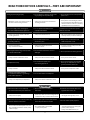 4
4
-
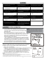 5
5
-
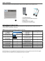 6
6
-
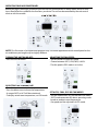 7
7
-
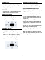 8
8
-
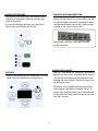 9
9
-
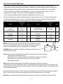 10
10
-
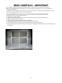 11
11
-
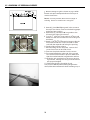 12
12
-
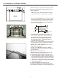 13
13
-
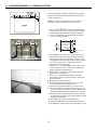 14
14
-
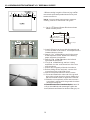 15
15
-
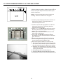 16
16
-
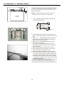 17
17
-
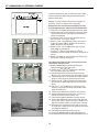 18
18
-
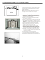 19
19
-
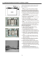 20
20
-
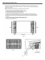 21
21
-
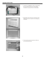 22
22
-
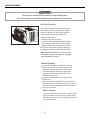 23
23
-
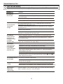 24
24
-
 25
25
-
 26
26
-
 27
27
-
 28
28
-
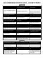 29
29
-
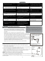 30
30
-
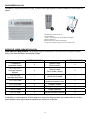 31
31
-
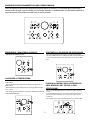 32
32
-
 33
33
-
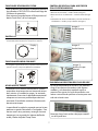 34
34
-
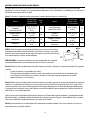 35
35
-
 36
36
-
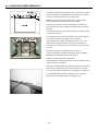 37
37
-
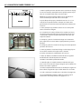 38
38
-
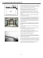 39
39
-
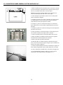 40
40
-
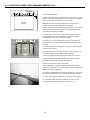 41
41
-
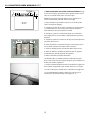 42
42
-
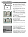 43
43
-
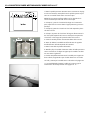 44
44
-
 45
45
-
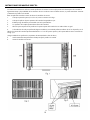 46
46
-
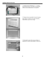 47
47
-
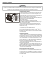 48
48
-
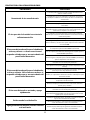 49
49
-
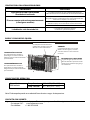 50
50


Impecca ITAC10KS21 Manual de usuario
- Categoría
- Barbacoas
- Tipo
- Manual de usuario
- Este manual también es adecuado para
en otros idiomas
- English: Impecca ITAC10KS21 User manual
Artículos relacionados
Otros documentos
-
Carrier 52F Series Guía del usuario
-
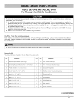 Kenmore Elite 25377085510 Guía de instalación
-
GE Appliances AKCQ14DCH El manual del propietario
-
Keystone KSTAT12-1A Manual de usuario
-
Fedders A6U10W2A El manual del propietario
-
Kenmore Elite 25376135313 Guía de instalación
-
Arctic King AKTW+12CR4-2 Installation & Operation Manual
-
-
Westinghouse 7500400 Instrucciones de operación
-
