Rockford Fosgate T1S1-12 Installation & Operation Manual
- Categoría
- Altavoces
- Tipo
- Installation & Operation Manual

Installation & Operation
T1S1-10 T1S2-10
T1S1-12 T1S2-12
SLIM
SUBWOOFERS
Serial Number: Date of Purchase:

2
Dear Customer,
Congratulations on your purchase of the world’s finest brand of car audio
products. At Rockford Fosgate we are fanatics about musical reproduc-
tion at its best, and we are pleased you chose our product. Through
years of engineering expertise, hand craftsmanship and critical testing
procedures, we have created a wide range of products that reproduce
music with all the clarity and richness you deserve.
For maximum performance we recommend you have your new Rockford
Fosgate product installed by an Authorized Rockford Fosgate Dealer,
as we provide specialized training through Rockford Technical Training
Institute (RTTI). Please read your warranty and retain your receipt and
original carton for possible future use.
Great product and competent installations are only a piece of the puzzle
when it comes to your system. Make sure that your installer is using
100% authentic installation accessories from Rockford Fosgate in your
installation. Rockford Fosgate has everything from RCA cables and
speaker wire to power wire and battery connectors. Insist on it! After all,
your new system deserves nothing but the best.
To add the finishing touch to your new Rockford Fosgate image, order
your Rockford accessories, which include everything from T-shirts to
hats.
Visit our web site for the latest information on all Rockford products
;
www.rockfordfosgate.com
or, in the U.S. call 1-800-669-9899 or FAX 1-800-398-3985. For all other
countries, call +001-480-967-3565 or FAX +001-480-966-3983.
Table of Content
If, after reading your manual, you still have questions regarding this prod-
uct, we recommend that you see your Rockford Fosgate dealer. If you need
further assistance, you can call us direct at 1-800-669-9899. Be sure to
have your serial number, model number and date of purchase available
when you call.
Safety
This symbol with “WARNING” is intended
to alert the user to the presence of important
instructions. Failure to heed the instructions
will result in severe injury or death.
This symbol with “CAUTION” is intended to
alert the user to the presence of important
instructions. Failure to heed the instructions
can result in injury or unit damage.
• To prevent injury and damage to the unit, please read and follow the
instructions in this manual. We want you to enjoy this system, not get
a headache.
• If you feel unsure about installing this system yourself, have it installed
by a qualified Rockford Fosgate technician.
• Before installation, disconnect the battery negative (-) terminal to
prevent damage to the unit, fire and/or possible injury.
Introduction
©2014 Rockford Corporation. All Rights Reserved. ROCKFORD FOSGATE and associated logos where applicable are registered trademarks of Rockford Corporation
in the United States and/or other countries. All other trademarks are the property of their respective owners. Specifications subject to change without notice.
PRACTICE SAFE SOUND
Continuous exposure to sound pressure levels over 100dB may cause
permanent hearing loss. High powered auto sound systems may
produce sound pressure levels well over 130dB. Use common sense
and practice safe sound.
PRATIQUEZ UNE ÉCOUTE SANS RISQUES
Une exposition continue à des niveaux de pression acoustique upérieurs à
100 dB peut causer une perte d’acuité auditive permanente. Les systèmes
audio de forte puissance pour auto peuvent produire des niveaux de
pression acoustique bien au-delà de 130 dB. Faites preuve de bon sens et
pratiquez une écoute sans risques
PRACTIQUE EL SONIDO SEGURO
El contacto continuo con niveles de presión de sonido superiores a 100
dB puede causar la pérdida permanente de la audición. Los sistemas de
sonido de alta potencia para automóviles pueden producir niveles de
presión de sonido superiores a los 130 dB. Aplique el sentido común y
practique el sonido seguro.
PRAKTIZIEREN SIE SICHEREN SOUND
Fortgesetzte Geräuschdruckpegel von über 100 dB können beim
Menschen zu permanentem Hörverlust führen. Leistungsstarke
Autosoundsysteme können Geräuschdruckpegel erzeugen, die weit über
130 dB liegen. Bitte wenden Sie gesunden Menschenverstand an und
praktizieren Sie sicheren Sound.
OSSERVATE LE REGOLE DEL SUONO SENZA PERICOLI
La costante esposizione a livelli di pressione acustica al di sopra dei
100dB possono causare la perdita permanente dell’udito. I sistemi
audio ad alta potenza possono produrre livelli di pressione acustica ben
superiori ai 130dB. Si consiglia il buon senso e l’osservanza delle regole
del suono senza pericoli
2 Introduction
3 Specifications
4-5 Enclosures
Sealed or Vented
Wiring
6-7 Additional Languages
French
Spanish
German
Italian
8 Limited Warranty Information

3
Specifications
Model T1S1-10 T1S2-10 T1S1-12 T1S2-12
Nominal Impedance (Ohms) 1 Ω 2 Ω 1 Ω 2 Ω
Frequency Response (Hz) 32-250 28-250 27-250 28-250
Voice Coil Diameter - inch
(mm)
2.5 (4-Layer)
(63.5)
2.5 (4-Layer)
(63.5)
3 (4-Layer)
(76)
3 (4-Layer)
(76)
Displacement - cu. ft.
(Liter)
0.03
(0.82)
0.03
(0.82)
0.11
(3.11)
0.11
(3.11)
Fs - Free Air Resonance (Hz) 42.0 44.0 36.0 37.0
Qts 0.95 1.05 0.89 1.06
Vas - cu. ft.
(Liter)
0.46
(13)
0.46
(13)
1.14
(32.2)
1.14
(32.2)
Xmax - inch
(mm)
0.50
(14.2)
0.50
(14.2)
0.60
(15)
0.60
(15)
SPL (dB @ 1w/1m) 82 83 84 84
Power Handling - Watts
(RMS/Peak)
500/1000 500/1000 600/1200 600/1200
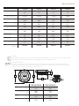
Model T1S1-10/ T1S2-10 T1S1-12/T1S2-12
A - Overall Diameter - inch
(mm)
10.83
(275)
13
(330)
B- Screw Hole Dia. - inch
(mm)
10.16
(258)
12.28
(312)
C- Mounting Dia - inch
(mm)
9.13
(232)
11.22
(285)
D - Mounting Depth - inch
(mm)
3
(76.5)
3
(76.5)
CEA 2031
Power handling on Rockford Fosgate speakers conform to CEA-2031 industry standards. This means your speaker has the capacity to handle
power under continuous demand, not instantaneous power handling that over time can damage voice coils.
VERIFIED WITH KLIPPEL
To adorn the ‘Verified with Klippel’ mark, the qualifying company’s loudspeaker engineering personnel must be trained and certified by
Klippel prior to using the three separate Klippel systems to design, develop and test. Rockford Fosgate has made the investment in Klippel to
deliver the best possible speakers and subwoofers to their customers.
A B
D
C
PUSH
to attach
wire
PUSH
to attach
wire

4
Enclosures
Carton Contents
• T1 Subwoofer with Trim Ring
• (12) Mounting Screws
• (4) Trim Ring Screws
• (1) Socket head driver bit
• Installation and Operation Manual
Recommended Enclosures
This manual outlines two specific types of enclosures that provide distinctly dif-
ferent performance. This section is to help you decide which type is best for your
application.
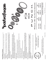
Sealed Enclosures
Sealed enclosures are the simplest to build. The most important part of building
a sealed enclosure is to make sure that the enclosure is airtight. Using glue and
some type of sealant on all seams will ensure solid construction and prevent air
leaks. The box volume will directly impact the performance of the speaker. Larger
enclosures will provide flatter response and deeper bass where smaller boxes will
provide a bump in the response curve and generally higher output for greater SPL.
Advantages of sealed enclosures:
• Small enclosures
• Linear (Flat) response
• No port noise
• High power handling at all frequencies
• Excellent for sound quality
• Extended low frequency output when compared to vented enclosures
Vented Enclosures
Vented enclosures vary only from the sealed enclosure in that a vent or port is
added to “tune” the enclosure. The enclosures recommended are designed for
great overall performance. Larger boxes tend to be easy to tune to lower frequen-
cies while medium and small boxes are easier to tune to higher frequencies. The
vented design is less linear in response than the sealed box but with noticeably
more output at the tuning frequency.
Advantages of vented enclosures:
• Higher average output than sealed
• Tuning frequency can be easily adjusted by changing port length
• Deep bass response with lower power requirements
• Great for high output with limited power
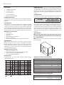
Vented vs Sealed
The graph shown here is a sample of how the F3 drop-off point differs between
sealed and vented enclosures.
Building an Enclosure
To work properly, the walls of the enclosure must be rigid and not flex when sub-
jected to the high pressures generated by the speaker’s operation. For optimum
performance, we recommend using 3/4” MDF (Medium Density Fiberboard) and
internal bracing. The enclosure should be glued together and secured with nails
or screws.
Calculating Volume
Calculating volume is merely a matter of measuring the dimensions in inches and
using the formula: H x W x D divided by 1728 (cubic feet). See block below.
Box Volume Height” x Width” x Depth”
Divided by (cubic feet) 1728
If two facing sides are of uneven length, add them together and divide by two to
take the average. Using this number will give you the volume without the necessity
of calculating the box in sections and adding the sections together. The thickness
of the baffle material reduces the internal volume so this must be subtracted from
the outside dimensions to determine the internal volume. The speaker itself also
reduces the internal volume. The amount of air displaced by each model is listed
on the specification sheet and should also be subtracted from the gross volume
calculation.
Sealed Enclosure
NOTE: Vb is the internal volume, before any speaker and/or port dis-
placement is added. All external dimensions were based on the use of
3/4” (1.90cm) materials.
NOTE: When using enclosures other than recommended, call Technical Support
for correct application.
Optimum Sealed Enclosure Recommendation
Sealed Enclosures 10” 12”
Total Internal Volume cu. ft. (Liter) 0.80 (22.62) 1.15 (32.56)
Woofer Displacement cu. ft. (Liter) 0.03 (0.82) 0.11 (3.11)
V
b
- Internal Area cu. ft. (Liter) 0.77 (21.8) 1.04 (29.45)
F
3
- 3dB Point (Hz) 40.3 39.9
Qtc - Enclosure Damping 1.10 1.18
H - Height - inch (cm) 12 (30.48) 14.5 (36.83)
W - Width - inch (cm) 18 (45.72) 22.5 (57.15)
D - Depth - inch (cm) 9.5 (24.13) 9.5 (24.13)
Recommended Sealed Enclosure Volume Range
Sealed Enclosures 10” 12”
V
b
- Volume range cu. ft.
(Liter)
0.5 to 1.0
(14.16 to 28.32)
0.75 to 1.25
(21.24 to 35.40)
60.0
70.0
80.0
90.0
100.0
110.0
120.0
130.0
10.0 20.0 40.0 60.0 80.0 100.0 200.0
Frequency, Hz
Sealed Box Vented Box
H
W
D

5
Enclosures
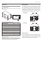
Vented Enclosures
NOTE: Vb is the internal volume, before any speaker and/or port dis-
placement is added. All external dimensions were based on the use of
3/4” (1.90cm) materials.
NOTE: When using enclosures other than recommended, call Technical Support
for correct application.
Optimum Vented (Ported) Enclosure Sizes
Vented Enclosures 10” 12”
Total Internal Volume cu. ft. (Liter) 1.5 (42.48) 2.0 (56.63)
Woofer Displacement cu. ft. (Liter) 0.03 (0.82) 0.11 (3.11)
Port Displacement cu. ft. (Liter) 0.12 (3.4) 0.09 (2.55)
V
b
- Internal Area cu. ft. (Liter) 1.35 (38.23) 1.8 (50.97)
F
B
- Tuning Frequency (Hz) 40 35
F
3
- 3dB Point (Hz) 30 28
H - Height - inch (cm) 12.0 (30.48) 14.5 (36.83)
W - Width - inch (cm) 20.0 (50.8) 22.5 (57.15)
D - Depth - inch (cm) 15.0 (38.1) 14.25 (36.2)
P - Port Diameter and Length - inch (cm) 4 x 14.25
(10.16 x36.2 )
4 x 13
(10.16 x33.02)
NOTE: The port shown can be placed on any face of the enclosure as long as the
port ends are not obstructed.
NOTE:
When using vented enclosures, for maximum reliability and power han-
dling ensure, that a subsonic or “infrasonic” filter at or above 27Hz is used so
that only usable low frequency signals are sent to the subwoofer.
Wiring Configurations
By varying the wiring configuration of your speakers you can create an impedance
load to match your system. Altering the wiring configurations gives a range of
options for impedance loads. Series, Parallel, or Series-Parallel wiring configura-
tions are different techniques for wiring speakers that provide different loads. Se-
ries configuration is a string method where speakers are wired end to end. Parallel
configuration uses two or more speakers wired across common terminals. Series-
Parallel configuration combines both techniques. Choose the wiring diagram that
corresponds to the number of woofers and the impedance of your amplifier.
Subwoofer Crossovers
There are two operational types of crossovers, passive and active. Passive cross-
overs (coils or inductors) are placed on the speaker leads between the amplifier
and speaker. An active crossover is an electronic filter that separates the audio
signal fed to different amplifiers. For optimum subwoofer performance, we recom-
mend using an active 80-100Hz low-pass crossover at 12dB/octave.
3/4" MDF
H
W
D
P
(2) 2 ohm SVC Speaker = 1 ohm Load
Parallel Wiring
2Ω 2Ω
1Ω
(2) 1 ohm SVC Speaker = 2 ohm Load
Series Wiring
1Ω 1Ω
2Ω

6
Enceintes recommandées
Ce manuel décrit deux types particuliers d’enceintes aux performances tout à fait distinctes.
Cette section vous permettra de décider celui qui vous conviendra le mieux.
Enceintes Étanches
Les enceintes étanches sont les plus faciles à fabriquer.À cet égard, la chose la plus impor-
tante dans leur fabrication est de vous assurer qu’elles sont vraiment hermétiques.Appliquez
de la colle et un produit d’étanchéité sur tous les joints pour solidifier l’ensemble et empêcher
toute fuite d’air. Le volume du caisson influe directement sur la performance du haut-parleur.
Les enceintes de plus grande dimension délivrent une réponse uniforme en fréquence avec
des graves profonds alors que les enceintes plus petites ont une courbe de réponse plus
pr noncée et un rendement généralement supérieur pour un niveau de pression acou tique
plus élevé.
Avantage des enceintes étanches:
• Petites enceintes
• Réponse linéaire (uniforme)
• Pas de bruit d’évent
• Puissance élevée sur toutes les fréquences
• Excellentes en ce qui concerne la qualité du son
Enceintes À Évent
Les enceintes à évent se distinguent des enceintes étanches du fait qu’on y ajoute un
évent ou port pour les « accorder ». Les enceintes reco mandées sont conçues pour of-
frir d’excellentes performances. Il est généralement plus facile d’accorder les caissons plus
grands pour l’obtention de basses fréquences et les caissons moyens et petits pour des
fréquences plus élevées. Les enceintes à évent
ont une réponse moins linéaire que les enceintes étanches mais dégagent nettement plus de
puissance à la fréquence d’accord.
Avantages des enceintes à évent :
• Rendement moyen supérieur par rapport aux modèles étanches
• La fréquence d’accord peut être facilement réglée en changeant la lo gueur de l’évent
• Reproduction profonde des basses avec une puissance d’entrée moindre
• Excellent choix pour un rendement élevé à faible puissance d’entrée
Construire Un Caisson
Pour fonctionner convenablement les parois du caisson doivent être rigides lorsqu’elles
sont soumises aux hautes pressions dues au fonctionnement du haut-parleur.Nous vous
recommandons d’utiliser des panneaux de bois aggloméré à haute ou moyenne densité de
particules de type “MDF”.Ces panneaux sont disponibles dans la plupart des magasins de
bricolage. Pour un caisson de grand volume il est recommandé de placer des renforts à
l’intérieur du caisson. Les différents côtés devront être collés (colle à bois) et vissés (ou
éventuellement cloués). Il est recommandé de mettre un joint de silicone dans les arêtes
internes du caisson afin d’éviter les fuites d’air.
Calcu duVolume
On calcule le volume en mesurant la dimension de chaque côté et en utilisant la formule
suivante:
Volume du caisson Hauteur (cm) x Longueur (cm) x Largeur (cm)
Divisé près (Litres) 1000
Si les due côtés qui se font face n’ont pas la même longueur, additionnez les et divisez
le résultat par deux pour obtenir la moyenne des deux longueurs.Utilisez le nombre ainsi
obtenu dans la formule pour déterminer le litrage.Cette méthode permet d’obtenir le volume
du caisson sans devoir faire de calculs compliqués de section de volume. L’épaisseur du
matériau dont est fait le caisson réduit le volume interne de celui-ci. Lorsqu’on mesure les
côtés du caisson il ne faut donc pas oublier d’oter des mesures l’epaisseur du matériau. Le
haut-parleur lui-même diminue le volume in terne du caisson. Le volume d’air déplacé par
chaque modèle de haut-parleur est repris dans les spécifications techniques et doit égale-
ment être soustrait du volume total.
Configuration du câblage
En variant la configuration du câblage de vos haut-parleurs, vous pouvez créer une charge
d’impédance correspondant à votre système. La modification des configurations de câblage
offre tout un choix d’options en ce qui concerne la charge d’impédance. Les câblages sé-
rie, parallèle, ou série/parallèle sont des techniques permettant de câbler les haut-parleurs
de manière à produire des charges différentes. La configuration série consiste à câbler les
haut-parleurs à la chaîne, bout à bout. La configuration parallèle utilise deux ou plusieurs
haut-parleurs branchés sur des bornes communes. La configuration série/parallèle combine
les deux techniques.Choisissez le schéma ci-dessous qui correspond au nombre de haut-
parleurs de graves et à l’impédance de votre ampli.
Filtres de subwoofer
On distingue deux types de filtres opérationnels : passif et actif. Les filtres passifs (bobines
ou inducteurs) sont placés sur les fils de haut-parleur, entre l’ampli et le haut-parleur.Un filtre
actif est un filtre électronique qui sépare le signal audio envoyé à différents amplis. Pour
obtenir une performance optimale du subwoofer, nous recommandons l’utilisation d’un filtre
actif passe-bas 80-100 Hz à 12 dB/octave.
Cajas recomendadas
Este manual delinea dos tipos específicos de cajas que producen rendimientos inconfund-
iblemente diferentes. Esta sección es para ayudarle a decidir cuál tipo es el mejor para su
aplicación.
Cajas CERRADAS
Las cajas cerradas son las más fáciles de hacer. La parte más importante de la construcción
de una caja cerrada es garantizar su hermetismo. El uso de pegante y algún tipo de sellador
en todos los bordes garantizará una construcción sólida y evitará fugas de aire. El volumen
de la caja impacta directamente el rendimiento del altavoz. Las cajas más grandes ofrecen
una respuesta más plana y un bajo más profundo,mientras que las más pequeñas ofrecen un
incremento en la curva de respuesta y generalmente una salida mayor, para un mayor NPS.
Ventajas de las cajas cerradas:
• Cajas pequeñas
• Respuesta lineal (plana)
• No hay ruido del orificio
• Capacidad de alta potencia en todas las frecuencias
• Excelentes para la calidad del sonido
Cajas con Orificios
Las cajas con orificios sólo se diferencian de las cerradas en que se les hace un orificio para
“sintonizarlas.” Las cajas recomendadas son diseñadas para un gran rendimiento general.
Las cajas grandes tienden a ser fáciles de sintonizar en las frecuencias graves,mientras que
medianas y pequeñas son más fáciles de sintonizar en las frecuencias más altas. El diseño
con orificios es de una respuesta menos lineal que el de la caja cerrada, pero tiene una salida
notablemente mayor en la frecuencia de sintonización.
Ventajas de las cajas con orificios:
• Un promedio de salida mayor que las cerradas
• La frecuencia de sintonización se ajusta fácilmente al cambiar la longitud del orificio
• Respuesta de bajo profundo con menos exigencia de potencia
• Fabulosas para salida alta con potencia limitada
Construcción de una caja
Para un buen funcionamiento las paredes de la caja deben ser rigidas y no se deben doblar
cuando sean sometidas a la gran presión que ejerce el funcionamiento del altavoz. Reco-
mendamos usar madera comprimida de mediana densidad, de 1.9 cm o fibra de media den-
sidad. Si la caja es muy grande es necessario reforzarla internamente. Las juntas deben ser
encoladas y aseguradas con tornillos o grapas. Internamente los bordes deben ser sellados
con silicona para prevenir las fugas de aire. La cola para madera es la mejor opción.
Cálculo deVolúmenes
Para calcular el volumen sólo se han de medir las dimensiones en centímetros y aplicar la
fórmula:
Volumen du la caja Alto(cm)xAncho(cm) x Profundidad(cm)
Dividido por (en litros) 1000
Si dos caras opuestas son de diferente tamaño, súmelas y divida el total por dos para ob-
tener el promedio.Usando esta técnica se ahorrara el cálculo por secciones. El espesor del
material con que está construida la caja reduce el volumen interno, de manera que ha de
restarse de las dimensiones exteriores para determinar el volumen interior. La cantidad de
aire que ocupa cada modelo viene especificado en la hoja de características y también debe
sustraerse para obtener el volumen neto interior.
Configuraciones del cableado
Al variar la configuración del cableado de los altavoces, usted puede crear una impedancia
de carga que iguale a su sistema. La alteración de la configuración de los cables da una
gama de opciones para impedancia de carga. Las configuraciones en serie, paralela o en
serie-paralela son técnicas diferentes para el cableado de los altavoces que ofrecen cargas
diferentes. La configuración en serie es un método en cadena en el que los altavoces se
conectan de punta a punta. La configuración paralela usa dos o más altavoces conectados
a lo largo de terminales en común. La configuración en serie-paralela combina ambas téc-
nicas. Escoja el diagrama que corresponda al número de altavoces para sonidos graves y la
impedancia de su amplificador
Filtros deTransición del altavoz para sonidos graves
(Subwoofer X-Over)
Hay dos tipos funcionales de filtros de transición, pasivos y activos. Los pasivos (bobinas o
inductores) se conectan a los cables del altavoz, entre el amplificador y el altavoz.Un filtro de
transición activo es un filtro electrónico que separa la señal de audio alimentada a diferentes
amplificadores. Para un rendimiento óptimo del altavoz para sonidos graves, recomendamos
el uso de un filtro de transición activo de 80-100Hz, paso bajo a 12dB/octava.
Français Español

7
Empfohlene Gehäuse
DieseAnleitung beschreibt zwei spezifischeTypen von Gehäusen, die grundsätzlich ver-
schiedene Performancemerkmale bieten.DieserAbschnitt soll Ihnen dabei helfen zu
entscheiden,welcher der besteTyp für IhreAnwendung ist.
Geschlossene Gehäuse
Geschlossene Gehäuse lassen sich am leichtesten bauen.Der wichtigsteAspekt beim Bau
eines geschlossenen Gehäuses ist zu gewährleisten, dass es luftdicht ist. DieVerwendung
von Klebstoff und anderen Dichtungsmitteln an allen Fugen gewährleistet eine solide Kon-
struktion und verhindert Luftverlust.Das Gehäusevolumen wirkt sich unmittelbar auf die Per-
formance des Lautsprechers aus.Größere Gehäuse bieten eine flachere Reaktion und tiefere
Bässe,wohingegen kleinere Gehäuse eineAbweichung in der Reaktionskurve bieten und im
Allgemeinen durch höhere Leistung zu einem höheren Schalldruckpegel führen.
Vorteile von geschlossenen Gehäusen:
• Kleine Gehäuse
• Lineare (flache) Reaktion
• Keine Öffnungsgeräusche
• Hohe Nennbelastbarkeit in allen Frequenzbereichen
• Ausgezeichnete Klangqualität
Belüftete Gehäuse
Belüftete Gehäuse unterscheiden sich von geschlossenen Gehäusen nur in sofern, als dass
ein Luftschlitz bzw. eine Öffnung hinzugefügt wird, um das Gehäuse zu „stimmen“.Die emp-
fohlenen Gehäuse sind für hervorragende Gesamtperformance konstruiert.Größere Gehäuse
lassen sich in der Regel leichter auf niedrigere Frequenzen abstimmen,wohingegen sich mit-
tlere und kleine Gehäuse leichter auf höhere Frequenzen abstimmen lassen.Das belüftete
Design zeigt eine weniger lineare Reaktion als das geschlossene Gehäuse, erbringt jedoch
eine feststellbar höhere Leistung auf der abgestimmten Frequenz.
Vorteile von belüfteten Gehäusen:
• Höhere Durchschnittsleistung als geschlossene Gehäuse
• Abstimmfrequenz kann leicht durch Änderung der Öffnungslänge a gepasst werden
• Tiefes Bassverhalten bei geringerem Kraftbedarf
• Gut geeignet für hohe Leistung bei beschränkter Kraft
Bau des Gehäuses
Um ordnungsgemäß zu funktionieren,müssen die Gehäusewände steif sein und dürfen nicht
nachgeben,wenn sie dem hohen Druck ausgesetzt sind, der bei Betrieb des Lautsprechers
entsteht. Für optimale Performance empfehlen wir Faserplatte mittlerer Dichte (Stärke ca. 1,9
cm) und interneAussteifungen.Das Gehäuse wird verleimt und mit Nägeln oder Schrauben
befestigt.Da Faserplatte luftdurchlässig ist, wird geraten, das Gehäuse von außen mit Poly-
urethan zu behandeln.
Berechnung desVolumens
Zur Berechnung desVolumens einfach die Maße feststellen und folgende Formel anwenden:
Gehäuse-Volumen Höhe (cm) x Breite (cm) xTiefe (cm)
Vorbei geteilt (Liter) 1000
Sind zwei gegenüber liegende Seiten ungleich lang, die Durchschnittslänge der beiden
Seiten berechnen.DasVolumen lässt sich mithilfe dieser Zahl berechnen, ohne das Gehäuse
inAbschnitten berechnen zu müssen.Die Stärke des Resonanzwandmaterials reduziert das
Innenvolumen und muss daher zur Feststellung des Innenvolumens vomAußenvolumen
subtrahiert werden.Der Lautsprecher selbst reduziert das Innenvolumen ebenfalls.Die Luft-
verdrängung für jedes Modell ist unterTechnische Daten aufgeführt und muss bei der Gesa-
mtkalkulation desVolumens ebenfalls subtrahiert werden.
Verkabelungskonfigurationen
DurchVeränderung derVerkabelungskonfiguration Ihrer Lautsprecher können Sie eine Imped-
anzlast herstellen, die Ihrem System entspricht. Bietet dieVeränderung derVerkabelungskon-
figurationen eine Reihe von Optionen für die Impedanzlast. Reihen-, Parallel- oder Reihen-
Parallel-Verkabelungen sind verschiedeneTechniken für dieVerkabelung von Lautsprechern,
die unterschiedliche Belastungen bieten.Die Reihenkonfiguration ist eine Reihenmethode,
bei der die Lautsprecher von Ende zu Ende verkabelt werden.Die Parallelkonfiguration ver-
wendet mindestens zwei Lautsprecher, die über gemeinsameAnschlüsse verkabelt werden.
Die Reihen- Parallel-Konfiguration kombiniert beideTechniken.Wählen Sie das nachfolgende
Verkabelungsdiagramm aus, das der Zahl anTieftönern und der Impedanz Ihres Verstärkers
entspricht.
Subwoofer-Crossover
Es gibt zwei Betriebstypen für Crossover, und zwar passive und aktive. Passive Crossover
(Spulen oder Induktoren) werden auf den Lautsprecherkabeln zwischen Verstärker und
Lautsprecher platziert. Ein aktives Crossover ist ein elektronischer Filter, der dasAudiosignal
trennt, das verschiedenenVerstärkern zugeführt wird. Zur optimalen Subwoofer-Performance
empfehlen wir dieVerwendung von aktiven 80-100 Hz-Niedrigpass-Crossovern bei 12 dB/
Oktav.
Casse acustiche consigliate
Il presente manuale descrive a grandi linee due tipi di cassa acustica che forniscono prestazi-
oni distintamente diverse. La presente sezione mira ad aiutare a decidere quale sia il tipo
migliore per la propria applicazione.
Casse a chiusura ermetica
Le casse a chiusura ermetica sono le più semplici da costruire. La cosa più importante in
questo tipo di costruzione è di accertarsi che la chiusura sia a tenuta d’aria. L’uso di colla
e di un qualche altro tipo di mastice in tutti i punti di giuntura garantirà che la costruzione
sia solida ed eviterà le perdite d’aria. Il volume della cassa influirà in modo diretto sulle
prestazioni del diffusore. Le casse più grandi forniranno una risposta più piatta e bassi più
profondi, mentre quelle più piccole presenteranno una gobba nella curva di risposta e forni-
ranno in generale un’uscita più alta per un maggiore livello SPL.
Vantaggi delle casse a chiusura ermetica:
• Casse di dimensioni ridotte
• Risposta lineare (piatta)
• Nessun disturbo da apertura
• Gestione di potenza alta a tutte le frequenze
• Eccellente qualità del suono
• Ottima uscita di bassa frequenza a confronto delle casse con sfiato
Casse con sfiato
Le casse con sfiato differiscono da quelle a chiusura ermetica solo per il fatto che in esse è
praticata un’apertura o porta per “accordare” la cassa stessa. Le casse consigliate sono state
progettate per fornire una buona prestazione nell’insieme. Le casse più grandi sono gener-
almente più facili da accordare alla frequenze più basse, mentre quelle piccole e di misura
mediana sono più facili da accordare alle frequenze più alte. Il design con sfiato ha risposta
meno lineare delle casse a chiusura ermetica, ma possiede un’uscita notevolmente maggiore
alla frequenza di accordo.
Vantaggi delle casse con sfiato:
•Uscita media superiore alle casse chiuse
• La frequenza di accordo può essere regolata facilmente modificando la lunghezza
dell’apertura
• Risposta di bassi profondi con minore potenza
• Ottime per uscita alta con potenza limitata
Costruzione della cassa
Perché la cassa possa funzionare in modo corretto è necessario che le pareti siano rigide e
non si flettano quando sono assoggettate alle alte pressioni prodotte dal diffusore in opera-
zione. Per ottenere i migliori risultati si consiglia di usare MDF (pannello di fibre di densità
media) dello spessore di 3/4 di pollice. I pannelli della cassa dovrebbero essere uniti con
colla e tenuti assieme in modo sicuro con chiodi o viti.
Calcolo del volume
Il calcolo del volume consiste semplicemente nel prendere le misure in pollici e usare la
formula seguente:
Volume della casella
Altezza(cm) x Larghezza (cm) x Profondità
(cm)
Diviso vicino (nei litri) 1000
Se due lati hanno lunghezze diverse, sommare i due valori e dividere per due per ottenere il
valore medio. Il numero così ottenuto fornirà il volume senza doverlo calcolare dividendo la
cassa in sezioni e quindi sommando assieme i volumi delle diverse sezioni. Lo spessore del
materiale di diaframma riduce il volume interno e quindi lo si dovrà sottrarre alle dimensioni
esterne per calcolare il volume. Anche l’altoparlante vero e proprio riduce il volume interno.
Il volume d’aria occupato da ciascun modello è indicato nel foglio dei dati tecnici e dovrà
essere sottratto dal volume lordo calcolato.
Configurazione d’impianto
Variando la configurazione d’impianto dei propri diffusori si può creare un carico d’impedenza
accoppiato a quello del sistema. La modifica della configurazione d’impianto produce una
gamma di scelte di carico d’impedenza. Le configurazioni d’impianto in serie, in parallelo, in
serie-parallelo rappresentano diverse tecniche di collegamento dei fili che producono carichi
diversi. La configurazione in serie rappresenta un metodo di collegamento in cui i diffusori
sono collegati uno dopo l’atro. La configurazione in parallelo utilizza due o più diffusori
collegati con terminali comuni. La configurazione in serie-parallelo unisce le due tecniche.
Scegliere lo schema d’impianto che corrisponde al proprio numero di woofer e all’impedenza
dell’amplificatore.
Crossover dei subwoofer
Ci sono due tipi di crossover, passivo e attivo. I crossover passivi (bobine o induttori) sono
posti sui fili dei diffusori tra il diffusore e l’amplificatore. Il crossover attivo è un filtro elettro-
nico che separa il segnale audio inviato a diversi amplificatori. Per ottimizzare le prestazioni
dei subwoofer, si consiglia di usare un crossover attivo passa-basso da 80-100 Hz a 12 dB/
ottava.
ItalianoDeutsch

8
Rockford Corporation offers a limited warranty on Rockford Fosgate products on the following terms:
Length of Warranty
POWER Amplifiers – 2 Years
BMW
®
Direct Fit Speakers – 2 Years
All other products - 1 Year
Any Factory Refurbished Product – 90 days (receipt required)
What is Covered
This warranty applies only to Rockford Fosgate products sold to consumers by Authorized Rockford Fosgate Dealers in the United States of America or its
possessions. Product purchased by consumers from an Authorized Rockford Fosgate Dealer in another country are covered only by that country’s Distribu-
tor and not by Rockford Corporation.
Who is Covered
This warranty covers only the original purchaser of Rockford product purchased from an Authorized Rockford Fosgate Dealer in the United States. In order
to receive service, the purchaser must provide Rockford with a copy of the receipt stating the customer name, dealer name, product purchased and date of
purchase.
Products found to be defective during the warranty period will be repaired or replaced (with a product deemed to be equivalent) at Rockford’s discretion.
What is Not Covered
1. Damage caused by accident, abuse, improper operations,water, theft, shipping.
2. Any cost or expense related to the removal or reinstallation of product.
3. Service performed by anyone other than Rockford or an Authorized Rockford Fosgate Service Center.
4. Any product which has had the serial number defaced, altered, or removed.
5. Subsequent damage to other components.
6. Any product purchased outside the U.S.
7. Any product not purchased from an Authorized Rockford Fosgate Dealer.
Limit on Implied Warranties
Any implied warranties including warranties of fitness for use and merchantability are limited in duration to the period of the express warranty set forth
above. Some states do not allow limitations on the length of an implied warranty, so this limitation may not apply. No person is authorized to assume for
Rockford Fosgate any other liability in connection with the sale of the product.
How to Obtain Service
Contact the Authorized Rockford Fosgate Dealer you purchased this product from. If you need further assistance, call 1-800-669-9899 for Rockford Cus-
tomer Service. You must obtain an RA# (Return Authorization number) to return any product to Rockford Fosgate. You are responsible for shipment of
product to Rockford.
EU Warranty
This product meets the current EU warranty requirements, see your Authorized dealer for details.
Warranty

Installation assistance available at:
www.rockfordfosgate.com/rftech
ROCKFORDFOSGATE.COM
600 South Rockford Drive • Tempe, Arizona 85281 United States
Direct: (480) 967-3565 • Toll Free: (800) 669-9899
Printed in Chin
a
121514 1230-58808-03
Transcripción de documentos
SLIM SUBWOOFERS Serial Number: T1S1-10 T1S2-10 T1S1-12 T1S2-12 Date of Purchase: Installation & Operation Introduction Dear Customer, Congratulations on your purchase of the world’s finest brand of car audio products. At Rockford Fosgate we are fanatics about musical reproduction at its best, and we are pleased you chose our product. Through years of engineering expertise, hand craftsmanship and critical testing procedures, we have created a wide range of products that reproduce music with all the clarity and richness you deserve. For maximum performance we recommend you have your new Rockford Fosgate product installed by an Authorized Rockford Fosgate Dealer, as we provide specialized training through Rockford Technical Training Institute (RTTI). Please read your warranty and retain your receipt and original carton for possible future use. Great product and competent installations are only a piece of the puzzle when it comes to your system. Make sure that your installer is using 100% authentic installation accessories from Rockford Fosgate in your installation. Rockford Fosgate has everything from RCA cables and speaker wire to power wire and battery connectors. Insist on it! After all, your new system deserves nothing but the best. To add the finishing touch to your new Rockford Fosgate image, order your Rockford accessories, which include everything from T-shirts to hats. Visit our web site for the latest information on all Rockford products; If, after reading your manual, you still have questions regarding this product, we recommend that you see your Rockford Fosgate dealer. If you need further assistance, you can call us direct at 1-800-669-9899. Be sure to have your serial number, model number and date of purchase available when you call. PRACTICE SAFE SOUND Continuous exposure to sound pressure levels over 100dB may cause permanent hearing loss. High powered auto sound systems may produce sound pressure levels well over 130dB. Use common sense and practice safe sound. PRATIQUEZ UNE ÉCOUTE SANS RISQUES Une exposition continue à des niveaux de pression acoustique upérieurs à 100 dB peut causer une perte d’acuité auditive permanente. Les systèmes audio de forte puissance pour auto peuvent produire des niveaux de pression acoustique bien au-delà de 130 dB. Faites preuve de bon sens et pratiquez une écoute sans risques PRACTIQUE EL SONIDO SEGURO El contacto continuo con niveles de presión de sonido superiores a 100 dB puede causar la pérdida permanente de la audición. Los sistemas de sonido de alta potencia para automóviles pueden producir niveles de presión de sonido superiores a los 130 dB. Aplique el sentido común y practique el sonido seguro. PRAKTIZIEREN SIE SICHEREN SOUND www.rockfordfosgate.com or, in the U.S. call 1-800-669-9899 or FAX 1-800-398-3985. For all other countries, call +001-480-967-3565 or FAX +001-480-966-3983. Fortgesetzte Geräuschdruckpegel von über 100 dB können beim Menschen zu permanentem Hörverlust führen. Leistungsstarke Autosoundsysteme können Geräuschdruckpegel erzeugen, die weit über 130 dB liegen. Bitte wenden Sie gesunden Menschenverstand an und praktizieren Sie sicheren Sound. Table of Content OSSERVATE LE REGOLE DEL SUONO SENZA PERICOLI 2 Introduction 3 Specifications La costante esposizione a livelli di pressione acustica al di sopra dei 100dB possono causare la perdita permanente dell’udito. I sistemi audio ad alta potenza possono produrre livelli di pressione acustica ben superiori ai 130dB. Si consiglia il buon senso e l’osservanza delle regole del suono senza pericoli 4-5 Enclosures Sealed or Vented Wiring 6-7 Additional Languages French Spanish German Italian 8 Limited Warranty Information Safety This symbol with “WARNING” is intended to alert the user to the presence of important instructions. Failure to heed the instructions will result in severe injury or death. This symbol with “CAUTION” is intended to alert the user to the presence of important instructions. Failure to heed the instructions can result in injury or unit damage. • To prevent injury and damage to the unit, please read and follow the instructions in this manual. We want you to enjoy this system, not get a headache. • If you feel unsure about installing this system yourself, have it installed by a qualified Rockford Fosgate technician. • Before installation, disconnect the battery negative (-) terminal to prevent damage to the unit, fire and/or possible injury. ©2014 Rockford Corporation. All Rights Reserved. ROCKFORD FOSGATE and associated logos where applicable are registered trademarks of Rockford Corporation in the United States and/or other countries. All other trademarks are the property of their respective owners. Specifications subject to change without notice. 2 Specifications Model T1S1-10 T1S2-10 T1S1-12 T1S2-12 1Ω 2Ω 1Ω 2Ω Frequency Response (Hz) 32-250 28-250 27-250 28-250 Voice Coil Diameter - inch (mm) 2.5 (4-Layer) (63.5) 2.5 (4-Layer) (63.5) 3 (4-Layer) (76) 3 (4-Layer) (76) Displacement - cu. ft. (Liter) 0.03 (0.82) 0.03 (0.82) 0.11 (3.11) 0.11 (3.11) Fs - Free Air Resonance (Hz) 42.0 44.0 36.0 37.0 Qts 0.95 1.05 0.89 1.06 Vas - cu. ft. (Liter) 0.46 (13) 0.46 (13) 1.14 (32.2) 1.14 (32.2) Xmax - inch (mm) 0.50 (14.2) 0.50 (14.2) 0.60 (15) 0.60 (15) 82 83 84 84 500/1000 500/1000 600/1200 600/1200 Nominal Impedance (Ohms) SPL (dB @ 1w/1m) Power Handling - Watts (RMS/Peak) CEA 2031 Power handling on Rockford Fosgate speakers conform to CEA-2031 industry standards. This means your speaker has the capacity to handle power under continuous demand, not instantaneous power handling that over time can damage voice coils. VERIFIED WITH KLIPPEL To adorn the ‘Verified with Klippel’ mark, the qualifying company’s loudspeaker engineering personnel must be trained and certified by Klippel prior to using the three separate Klippel systems to design, develop and test. Rockford Fosgate has made the investment in Klippel to deliver the best possible speakers and subwoofers to their customers. D A B C PUSH to attach wire Model T1S1-10/ T1S2-10 T1S1-12/T1S2-12 A - Overall Diameter - inch (mm) 10.83 (275) 13 (330) B- Screw Hole Dia. - inch (mm) 10.16 (258) 12.28 (312) C- Mounting Dia - inch (mm) 9.13 (232) 11.22 (285) D - Mounting Depth - inch (mm) 3 (76.5) 3 (76.5) PUSH to attach wire 3 Enclosures Building an Enclosure To work properly, the walls of the enclosure must be rigid and not flex when subjected to the high pressures generated by the speaker’s operation. For optimum performance, we recommend using 3/4” MDF (Medium Density Fiberboard) and internal bracing. The enclosure should be glued together and secured with nails or screws. Carton Contents • T1 Subwoofer with Trim Ring • (12) Mounting Screws • (4) Trim Ring Screws • (1) Socket head driver bit • Installation and Operation Manual Recommended Enclosures This manual outlines two specific types of enclosures that provide distinctly different performance. This section is to help you decide which type is best for your application. Sealed Enclosures Sealed enclosures are the simplest to build. The most important part of building a sealed enclosure is to make sure that the enclosure is airtight. Using glue and some type of sealant on all seams will ensure solid construction and prevent air leaks. The box volume will directly impact the performance of the speaker. Larger enclosures will provide flatter response and deeper bass where smaller boxes will provide a bump in the response curve and generally higher output for greater SPL. Advantages of sealed enclosures: • Small enclosures • Linear (Flat) response • No port noise • High power handling at all frequencies • Excellent for sound quality • Extended low frequency output when compared to vented enclosures Vented Enclosures Vented enclosures vary only from the sealed enclosure in that a vent or port is added to “tune” the enclosure. The enclosures recommended are designed for great overall performance. Larger boxes tend to be easy to tune to lower frequencies while medium and small boxes are easier to tune to higher frequencies. The vented design is less linear in response than the sealed box but with noticeably more output at the tuning frequency. Calculating Volume Calculating volume is merely a matter of measuring the dimensions in inches and using the formula: H x W x D divided by 1728 (cubic feet). See block below. Box Volume Height” x Width” x Depth” Divided by (cubic feet) 1728 If two facing sides are of uneven length, add them together and divide by two to take the average. Using this number will give you the volume without the necessity of calculating the box in sections and adding the sections together. The thickness of the baffle material reduces the internal volume so this must be subtracted from the outside dimensions to determine the internal volume. The speaker itself also reduces the internal volume. The amount of air displaced by each model is listed on the specification sheet and should also be subtracted from the gross volume calculation. Sealed Enclosure NOTE: Vb is the internal volume, before any speaker and/or port displacement is added. All external dimensions were based on the use of 3/4” (1.90cm) materials. NOTE: When using enclosures other than recommended, call Technical Support for correct application. H Advantages of vented enclosures: • Higher average output than sealed • Tuning frequency can be easily adjusted by changing port length • Deep bass response with lower power requirements • Great for high output with limited power Vented vs Sealed The graph shown here is a sample of how the F3 drop-off point differs between sealed and vented enclosures. 130.0 W D Optimum Sealed Enclosure Recommendation Sealed Enclosures Total Internal Volume cu. ft. (Liter) 120.0 110.0 10” 12” 0.80 (22.62) 1.15 (32.56) Woofer Displacement cu. ft. (Liter) 0.03 (0.82) 0.11 (3.11) Vb - Internal Area cu. ft. (Liter) 0.77 (21.8) 1.04 (29.45) 40.3 39.9 F3 - 3dB Point (Hz) 100.0 Qtc - Enclosure Damping 90.0 1.10 1.18 12 (30.48) 14.5 (36.83) W - Width - inch (cm) 18 (45.72) 22.5 (57.15) D - Depth - inch (cm) 9.5 (24.13) 9.5 (24.13) H - Height - inch (cm) 80.0 70.0 Recommended Sealed Enclosure Volume Range 60.0 10.0 20.0 Sealed Box 4 40.0 Vented Box 60.0 80.0 100.0 Frequency, Hz 200.0 Sealed Enclosures 10” 12” Vb - Volume range cu. ft. (Liter) 0.5 to 1.0 (14.16 to 28.32) 0.75 to 1.25 (21.24 to 35.40) Enclosures Vented Enclosures NOTE: Vb is the internal volume, before any speaker and/or port displacement is added. All external dimensions were based on the use of 3/4” (1.90cm) materials. NOTE: When using enclosures other than recommended, call Technical Support for correct application. Wiring Configurations By varying the wiring configuration of your speakers you can create an impedance load to match your system. Altering the wiring configurations gives a range of options for impedance loads. Series, Parallel, or Series-Parallel wiring configurations are different techniques for wiring speakers that provide different loads. Series configuration is a string method where speakers are wired end to end. Parallel configuration uses two or more speakers wired across common terminals. SeriesParallel configuration combines both techniques. Choose the wiring diagram that corresponds to the number of woofers and the impedance of your amplifier. 1Ω Parallel Wiring H 2Ω 3/4" MDF 2Ω W D P (2) 2 ohm SVC Speaker = 1 ohm Load Optimum Vented (Ported) Enclosure Sizes Vented Enclosures 10” 12” Total Internal Volume cu. ft. (Liter) 1.5 (42.48) 2.0 (56.63) Woofer Displacement cu. ft. (Liter) 0.03 (0.82) 0.11 (3.11) Port Displacement cu. ft. (Liter) 0.12 (3.4) 0.09 (2.55) Vb - Internal Area cu. ft. (Liter) 1.35 (38.23) 1.8 (50.97) FB - Tuning Frequency (Hz) 40 35 F3 - 3dB Point (Hz) 30 28 H - Height - inch (cm) 12.0 (30.48) 14.5 (36.83) W - Width - inch (cm) 20.0 (50.8) 22.5 (57.15) D - Depth - inch (cm) 15.0 (38.1) 14.25 (36.2) 4 x 14.25 4 x 13 (10.16 x36.2 ) (10.16 x33.02) P - Port Diameter and Length - inch (cm) NOTE: The port shown can be placed on any face of the enclosure as long as the port ends are not obstructed. NOTE: When using vented enclosures, for maximum reliability and power handling ensure, that a subsonic or “infrasonic” filter at or above 27Hz is used so that only usable low frequency signals are sent to the subwoofer. 2Ω Series Wiring 1Ω 1Ω (2) 1 ohm SVC Speaker = 2 ohm Load Subwoofer Crossovers There are two operational types of crossovers, passive and active. Passive crossovers (coils or inductors) are placed on the speaker leads between the amplifier and speaker. An active crossover is an electronic filter that separates the audio signal fed to different amplifiers. For optimum subwoofer performance, we recommend using an active 80-100Hz low-pass crossover at 12dB/octave. 5 Français Español Enceintes recommandées Ce manuel décrit deux types particuliers d’enceintes aux performances tout à fait distinctes. Cette section vous permettra de décider celui qui vous conviendra le mieux. Enceintes Étanches Les enceintes étanches sont les plus faciles à fabriquer.À cet égard, la chose la plus importante dans leur fabrication est de vous assurer qu’elles sont vraiment hermétiques.Appliquez de la colle et un produit d’étanchéité sur tous les joints pour solidifier l’ensemble et empêcher toute fuite d’air. Le volume du caisson influe directement sur la performance du haut-parleur. Les enceintes de plus grande dimension délivrent une réponse uniforme en fréquence avec des graves profonds alors que les enceintes plus petites ont une courbe de réponse plus pr noncée et un rendement généralement supérieur pour un niveau de pression acou tique plus élevé. Avantage des enceintes étanches: • Petites enceintes • Réponse linéaire (uniforme) • Pas de bruit d’évent • Puissance élevée sur toutes les fréquences • Excellentes en ce qui concerne la qualité du son Enceintes À Évent Les enceintes à évent se distinguent des enceintes étanches du fait qu’on y ajoute un évent ou port pour les « accorder ». Les enceintes reco mandées sont conçues pour offrir d’excellentes performances. Il est généralement plus facile d’accorder les caissons plus grands pour l’obtention de basses fréquences et les caissons moyens et petits pour des fréquences plus élevées. Les enceintes à évent ont une réponse moins linéaire que les enceintes étanches mais dégagent nettement plus de puissance à la fréquence d’accord. Avantages des enceintes à évent : • Rendement moyen supérieur par rapport aux modèles étanches • La fréquence d’accord peut être facilement réglée en changeant la lo gueur de l’évent • Reproduction profonde des basses avec une puissance d’entrée moindre • Excellent choix pour un rendement élevé à faible puissance d’entrée Construire Un Caisson Pour fonctionner convenablement les parois du caisson doivent être rigides lorsqu’elles sont soumises aux hautes pressions dues au fonctionnement du haut-parleur.Nous vous recommandons d’utiliser des panneaux de bois aggloméré à haute ou moyenne densité de particules de type “MDF”.Ces panneaux sont disponibles dans la plupart des magasins de bricolage. Pour un caisson de grand volume il est recommandé de placer des renforts à l’intérieur du caisson. Les différents côtés devront être collés (colle à bois) et vissés (ou éventuellement cloués). Il est recommandé de mettre un joint de silicone dans les arêtes internes du caisson afin d’éviter les fuites d’air. Calcu duVolume On calcule le volume en mesurant la dimension de chaque côté et en utilisant la formule suivante: Volume du caisson Hauteur (cm) x Longueur (cm) x Largeur (cm) Divisé près (Litres) 1000 Si les due côtés qui se font face n’ont pas la même longueur, additionnez les et divisez le résultat par deux pour obtenir la moyenne des deux longueurs.Utilisez le nombre ainsi obtenu dans la formule pour déterminer le litrage.Cette méthode permet d’obtenir le volume du caisson sans devoir faire de calculs compliqués de section de volume. L’épaisseur du matériau dont est fait le caisson réduit le volume interne de celui-ci. Lorsqu’on mesure les côtés du caisson il ne faut donc pas oublier d’oter des mesures l’epaisseur du matériau. Le haut-parleur lui-même diminue le volume in terne du caisson. Le volume d’air déplacé par chaque modèle de haut-parleur est repris dans les spécifications techniques et doit également être soustrait du volume total. Configuration du câblage En variant la configuration du câblage de vos haut-parleurs, vous pouvez créer une charge d’impédance correspondant à votre système. La modification des configurations de câblage offre tout un choix d’options en ce qui concerne la charge d’impédance. Les câblages série, parallèle, ou série/parallèle sont des techniques permettant de câbler les haut-parleurs de manière à produire des charges différentes. La configuration série consiste à câbler les haut-parleurs à la chaîne, bout à bout. La configuration parallèle utilise deux ou plusieurs haut-parleurs branchés sur des bornes communes. La configuration série/parallèle combine les deux techniques.Choisissez le schéma ci-dessous qui correspond au nombre de hautparleurs de graves et à l’impédance de votre ampli. Filtres de subwoofer On distingue deux types de filtres opérationnels : passif et actif. Les filtres passifs (bobines ou inducteurs) sont placés sur les fils de haut-parleur, entre l’ampli et le haut-parleur.Un filtre actif est un filtre électronique qui sépare le signal audio envoyé à différents amplis. Pour obtenir une performance optimale du subwoofer, nous recommandons l’utilisation d’un filtre actif passe-bas 80-100 Hz à 12 dB/octave. 6 Cajas recomendadas Este manual delinea dos tipos específicos de cajas que producen rendimientos inconfundiblemente diferentes. Esta sección es para ayudarle a decidir cuál tipo es el mejor para su aplicación. Cajas CERRADAS Las cajas cerradas son las más fáciles de hacer. La parte más importante de la construcción de una caja cerrada es garantizar su hermetismo. El uso de pegante y algún tipo de sellador en todos los bordes garantizará una construcción sólida y evitará fugas de aire. El volumen de la caja impacta directamente el rendimiento del altavoz. Las cajas más grandes ofrecen una respuesta más plana y un bajo más profundo,mientras que las más pequeñas ofrecen un incremento en la curva de respuesta y generalmente una salida mayor, para un mayor NPS. Ventajas de las cajas cerradas: • Cajas pequeñas • Respuesta lineal (plana) • No hay ruido del orificio • Capacidad de alta potencia en todas las frecuencias • Excelentes para la calidad del sonido Cajas con Orificios Las cajas con orificios sólo se diferencian de las cerradas en que se les hace un orificio para “sintonizarlas.” Las cajas recomendadas son diseñadas para un gran rendimiento general. Las cajas grandes tienden a ser fáciles de sintonizar en las frecuencias graves,mientras que medianas y pequeñas son más fáciles de sintonizar en las frecuencias más altas. El diseño con orificios es de una respuesta menos lineal que el de la caja cerrada, pero tiene una salida notablemente mayor en la frecuencia de sintonización. Ventajas de las cajas con orificios: • Un promedio de salida mayor que las cerradas • La frecuencia de sintonización se ajusta fácilmente al cambiar la longitud del orificio • Respuesta de bajo profundo con menos exigencia de potencia • Fabulosas para salida alta con potencia limitada Construcción de una caja Para un buen funcionamiento las paredes de la caja deben ser rigidas y no se deben doblar cuando sean sometidas a la gran presión que ejerce el funcionamiento del altavoz. Recomendamos usar madera comprimida de mediana densidad, de 1.9 cm o fibra de media densidad. Si la caja es muy grande es necessario reforzarla internamente. Las juntas deben ser encoladas y aseguradas con tornillos o grapas. Internamente los bordes deben ser sellados con silicona para prevenir las fugas de aire. La cola para madera es la mejor opción. Cálculo deVolúmenes Para calcular el volumen sólo se han de medir las dimensiones en centímetros y aplicar la fórmula: Volumen du la caja Alto(cm)xAncho(cm) x Profundidad(cm) Dividido por (en litros) 1000 Si dos caras opuestas son de diferente tamaño, súmelas y divida el total por dos para obtener el promedio.Usando esta técnica se ahorrara el cálculo por secciones. El espesor del material con que está construida la caja reduce el volumen interno, de manera que ha de restarse de las dimensiones exteriores para determinar el volumen interior. La cantidad de aire que ocupa cada modelo viene especificado en la hoja de características y también debe sustraerse para obtener el volumen neto interior. Configuraciones del cableado Al variar la configuración del cableado de los altavoces, usted puede crear una impedancia de carga que iguale a su sistema. La alteración de la configuración de los cables da una gama de opciones para impedancia de carga. Las configuraciones en serie, paralela o en serie-paralela son técnicas diferentes para el cableado de los altavoces que ofrecen cargas diferentes. La configuración en serie es un método en cadena en el que los altavoces se conectan de punta a punta. La configuración paralela usa dos o más altavoces conectados a lo largo de terminales en común. La configuración en serie-paralela combina ambas técnicas. Escoja el diagrama que corresponda al número de altavoces para sonidos graves y la impedancia de su amplificador Filtros deTransición del altavoz para sonidos graves (Subwoofer X-Over) Hay dos tipos funcionales de filtros de transición, pasivos y activos. Los pasivos (bobinas o inductores) se conectan a los cables del altavoz, entre el amplificador y el altavoz.Un filtro de transición activo es un filtro electrónico que separa la señal de audio alimentada a diferentes amplificadores. Para un rendimiento óptimo del altavoz para sonidos graves, recomendamos el uso de un filtro de transición activo de 80-100Hz, paso bajo a 12dB/octava. Deutsch Italiano Empfohlene Gehäuse DieseAnleitung beschreibt zwei spezifischeTypen von Gehäusen, die grundsätzlich verschiedene Performancemerkmale bieten.DieserAbschnitt soll Ihnen dabei helfen zu entscheiden,welcher der besteTyp für IhreAnwendung ist. Geschlossene Gehäuse Geschlossene Gehäuse lassen sich am leichtesten bauen.Der wichtigsteAspekt beim Bau eines geschlossenen Gehäuses ist zu gewährleisten, dass es luftdicht ist. DieVerwendung von Klebstoff und anderen Dichtungsmitteln an allen Fugen gewährleistet eine solide Konstruktion und verhindert Luftverlust.Das Gehäusevolumen wirkt sich unmittelbar auf die Performance des Lautsprechers aus.Größere Gehäuse bieten eine flachere Reaktion und tiefere Bässe,wohingegen kleinere Gehäuse eineAbweichung in der Reaktionskurve bieten und im Allgemeinen durch höhere Leistung zu einem höheren Schalldruckpegel führen. Vorteile von geschlossenen Gehäusen: • Kleine Gehäuse • Lineare (flache) Reaktion • Keine Öffnungsgeräusche • Hohe Nennbelastbarkeit in allen Frequenzbereichen • Ausgezeichnete Klangqualität Belüftete Gehäuse Belüftete Gehäuse unterscheiden sich von geschlossenen Gehäusen nur in sofern, als dass ein Luftschlitz bzw. eine Öffnung hinzugefügt wird, um das Gehäuse zu „stimmen“.Die empfohlenen Gehäuse sind für hervorragende Gesamtperformance konstruiert.Größere Gehäuse lassen sich in der Regel leichter auf niedrigere Frequenzen abstimmen,wohingegen sich mittlere und kleine Gehäuse leichter auf höhere Frequenzen abstimmen lassen.Das belüftete Design zeigt eine weniger lineare Reaktion als das geschlossene Gehäuse, erbringt jedoch eine feststellbar höhere Leistung auf der abgestimmten Frequenz. Vorteile von belüfteten Gehäusen: • Höhere Durchschnittsleistung als geschlossene Gehäuse • Abstimmfrequenz kann leicht durch Änderung der Öffnungslänge a gepasst werden • Tiefes Bassverhalten bei geringerem Kraftbedarf • Gut geeignet für hohe Leistung bei beschränkter Kraft Bau des Gehäuses Um ordnungsgemäß zu funktionieren,müssen die Gehäusewände steif sein und dürfen nicht nachgeben,wenn sie dem hohen Druck ausgesetzt sind, der bei Betrieb des Lautsprechers entsteht. Für optimale Performance empfehlen wir Faserplatte mittlerer Dichte (Stärke ca. 1,9 cm) und interneAussteifungen.Das Gehäuse wird verleimt und mit Nägeln oder Schrauben befestigt.Da Faserplatte luftdurchlässig ist, wird geraten, das Gehäuse von außen mit Polyurethan zu behandeln. Berechnung desVolumens Zur Berechnung desVolumens einfach die Maße feststellen und folgende Formel anwenden: Gehäuse-Volumen Höhe (cm) x Breite (cm) xTiefe (cm) Vorbei geteilt (Liter) 1000 Sind zwei gegenüber liegende Seiten ungleich lang, die Durchschnittslänge der beiden Seiten berechnen.DasVolumen lässt sich mithilfe dieser Zahl berechnen, ohne das Gehäuse inAbschnitten berechnen zu müssen.Die Stärke des Resonanzwandmaterials reduziert das Innenvolumen und muss daher zur Feststellung des Innenvolumens vomAußenvolumen subtrahiert werden.Der Lautsprecher selbst reduziert das Innenvolumen ebenfalls.Die Luftverdrängung für jedes Modell ist unterTechnische Daten aufgeführt und muss bei der Gesamtkalkulation desVolumens ebenfalls subtrahiert werden. Verkabelungskonfigurationen DurchVeränderung derVerkabelungskonfiguration Ihrer Lautsprecher können Sie eine Impedanzlast herstellen, die Ihrem System entspricht. Bietet dieVeränderung derVerkabelungskonfigurationen eine Reihe von Optionen für die Impedanzlast. Reihen-, Parallel- oder ReihenParallel-Verkabelungen sind verschiedeneTechniken für dieVerkabelung von Lautsprechern, die unterschiedliche Belastungen bieten.Die Reihenkonfiguration ist eine Reihenmethode, bei der die Lautsprecher von Ende zu Ende verkabelt werden.Die Parallelkonfiguration verwendet mindestens zwei Lautsprecher, die über gemeinsameAnschlüsse verkabelt werden. Die Reihen- Parallel-Konfiguration kombiniert beideTechniken.Wählen Sie das nachfolgende Verkabelungsdiagramm aus, das der Zahl anTieftönern und der Impedanz Ihres Verstärkers entspricht. Subwoofer-Crossover Es gibt zwei Betriebstypen für Crossover, und zwar passive und aktive. Passive Crossover (Spulen oder Induktoren) werden auf den Lautsprecherkabeln zwischen Verstärker und Lautsprecher platziert. Ein aktives Crossover ist ein elektronischer Filter, der dasAudiosignal trennt, das verschiedenenVerstärkern zugeführt wird. Zur optimalen Subwoofer-Performance empfehlen wir dieVerwendung von aktiven 80-100 Hz-Niedrigpass-Crossovern bei 12 dB/ Oktav. Casse acustiche consigliate Il presente manuale descrive a grandi linee due tipi di cassa acustica che forniscono prestazioni distintamente diverse. La presente sezione mira ad aiutare a decidere quale sia il tipo migliore per la propria applicazione. Casse a chiusura ermetica Le casse a chiusura ermetica sono le più semplici da costruire. La cosa più importante in questo tipo di costruzione è di accertarsi che la chiusura sia a tenuta d’aria. L’uso di colla e di un qualche altro tipo di mastice in tutti i punti di giuntura garantirà che la costruzione sia solida ed eviterà le perdite d’aria. Il volume della cassa influirà in modo diretto sulle prestazioni del diffusore. Le casse più grandi forniranno una risposta più piatta e bassi più profondi, mentre quelle più piccole presenteranno una gobba nella curva di risposta e forniranno in generale un’uscita più alta per un maggiore livello SPL. Vantaggi delle casse a chiusura ermetica: • Casse di dimensioni ridotte • Risposta lineare (piatta) • Nessun disturbo da apertura • Gestione di potenza alta a tutte le frequenze • Eccellente qualità del suono • Ottima uscita di bassa frequenza a confronto delle casse con sfiato Casse con sfiato Le casse con sfiato differiscono da quelle a chiusura ermetica solo per il fatto che in esse è praticata un’apertura o porta per “accordare” la cassa stessa. Le casse consigliate sono state progettate per fornire una buona prestazione nell’insieme. Le casse più grandi sono generalmente più facili da accordare alla frequenze più basse, mentre quelle piccole e di misura mediana sono più facili da accordare alle frequenze più alte. Il design con sfiato ha risposta meno lineare delle casse a chiusura ermetica, ma possiede un’uscita notevolmente maggiore alla frequenza di accordo. Vantaggi delle casse con sfiato: •Uscita media superiore alle casse chiuse • La frequenza di accordo può essere regolata facilmente modificando la lunghezza dell’apertura • Risposta di bassi profondi con minore potenza • Ottime per uscita alta con potenza limitata Costruzione della cassa Perché la cassa possa funzionare in modo corretto è necessario che le pareti siano rigide e non si flettano quando sono assoggettate alle alte pressioni prodotte dal diffusore in operazione. Per ottenere i migliori risultati si consiglia di usare MDF (pannello di fibre di densità media) dello spessore di 3/4 di pollice. I pannelli della cassa dovrebbero essere uniti con colla e tenuti assieme in modo sicuro con chiodi o viti. Calcolo del volume Il calcolo del volume consiste semplicemente nel prendere le misure in pollici e usare la formula seguente: Volume della casella Altezza(cm) x Larghezza (cm) x Profondità (cm) Diviso vicino (nei litri) 1000 Se due lati hanno lunghezze diverse, sommare i due valori e dividere per due per ottenere il valore medio. Il numero così ottenuto fornirà il volume senza doverlo calcolare dividendo la cassa in sezioni e quindi sommando assieme i volumi delle diverse sezioni. Lo spessore del materiale di diaframma riduce il volume interno e quindi lo si dovrà sottrarre alle dimensioni esterne per calcolare il volume. Anche l’altoparlante vero e proprio riduce il volume interno. Il volume d’aria occupato da ciascun modello è indicato nel foglio dei dati tecnici e dovrà essere sottratto dal volume lordo calcolato. Configurazione d’impianto Variando la configurazione d’impianto dei propri diffusori si può creare un carico d’impedenza accoppiato a quello del sistema. La modifica della configurazione d’impianto produce una gamma di scelte di carico d’impedenza. Le configurazioni d’impianto in serie, in parallelo, in serie-parallelo rappresentano diverse tecniche di collegamento dei fili che producono carichi diversi. La configurazione in serie rappresenta un metodo di collegamento in cui i diffusori sono collegati uno dopo l’atro. La configurazione in parallelo utilizza due o più diffusori collegati con terminali comuni. La configurazione in serie-parallelo unisce le due tecniche. Scegliere lo schema d’impianto che corrisponde al proprio numero di woofer e all’impedenza dell’amplificatore. Crossover dei subwoofer Ci sono due tipi di crossover, passivo e attivo. I crossover passivi (bobine o induttori) sono posti sui fili dei diffusori tra il diffusore e l’amplificatore. Il crossover attivo è un filtro elettronico che separa il segnale audio inviato a diversi amplificatori. Per ottimizzare le prestazioni dei subwoofer, si consiglia di usare un crossover attivo passa-basso da 80-100 Hz a 12 dB/ ottava. 7 Warranty Rockford Corporation offers a limited warranty on Rockford Fosgate products on the following terms: Length of Warranty POWER Amplifiers – 2 Years BMW® Direct Fit Speakers – 2 Years All other products - 1 Year Any Factory Refurbished Product – 90 days (receipt required) What is Covered This warranty applies only to Rockford Fosgate products sold to consumers by Authorized Rockford Fosgate Dealers in the United States of America or its possessions. Product purchased by consumers from an Authorized Rockford Fosgate Dealer in another country are covered only by that country’s Distributor and not by Rockford Corporation. Who is Covered This warranty covers only the original purchaser of Rockford product purchased from an Authorized Rockford Fosgate Dealer in the United States. In order to receive service, the purchaser must provide Rockford with a copy of the receipt stating the customer name, dealer name, product purchased and date of purchase. Products found to be defective during the warranty period will be repaired or replaced (with a product deemed to be equivalent) at Rockford’s discretion. What is Not Covered 1. 2. 3. 4. 5. 6. 7. Damage caused by accident, abuse, improper operations,water, theft, shipping. Any cost or expense related to the removal or reinstallation of product. Service performed by anyone other than Rockford or an Authorized Rockford Fosgate Service Center. Any product which has had the serial number defaced, altered, or removed. Subsequent damage to other components. Any product purchased outside the U.S. Any product not purchased from an Authorized Rockford Fosgate Dealer. Limit on Implied Warranties Any implied warranties including warranties of fitness for use and merchantability are limited in duration to the period of the express warranty set forth above. Some states do not allow limitations on the length of an implied warranty, so this limitation may not apply. No person is authorized to assume for Rockford Fosgate any other liability in connection with the sale of the product. How to Obtain Service Contact the Authorized Rockford Fosgate Dealer you purchased this product from. If you need further assistance, call 1-800-669-9899 for Rockford Customer Service. You must obtain an RA# (Return Authorization number) to return any product to Rockford Fosgate. You are responsible for shipment of product to Rockford. EU Warranty This product meets the current EU warranty requirements, see your Authorized dealer for details. 8 Installation assistance available at: 121514 1230-58808-03 Printed in China www.rockfordfosgate.com/rftech 600 South Rockford Drive • Tempe, Arizona 85281 United States Direct: (480) 967-3565 • Toll Free: (800) 669-9899 R O C K F O R D F O S G AT E . C O M-
 1
1
-
 2
2
-
 3
3
-
 4
4
-
 5
5
-
 6
6
-
 7
7
-
 8
8
-
 9
9


Rockford Fosgate T1S1-12 Installation & Operation Manual
- Categoría
- Altavoces
- Tipo
- Installation & Operation Manual
en otros idiomas
- français: Rockford Fosgate T1S1-12
- italiano: Rockford Fosgate T1S1-12
- English: Rockford Fosgate T1S1-12
- Deutsch: Rockford Fosgate T1S1-12
Artículos relacionados
-
 Rockford Fosgate RM18D4B Manual de usuario
-
Rockford Fosgate T2S2-16 Installation & Operation
-
 Rockford Fosgate Prime R1S4-12 Installation & Operation
-
 Rockford Fosgate M2-SVC Installation & Operation Manual
-
Rockford Fosgate R2 SHALLOW - DVC Series R2SD2-12 Especificación
-
 Rockford Fosgate M1D4-10 Manual de usuario
-
 Rockford Fosgate P3SD212 Manual de usuario
-
 Rockford Fosgate P3 Shallow Manual de usuario
-
 Rockford Fosgate T1S1-10 El manual del propietario
-
 Rockford Fosgate M2 ELEMENT READY M2D2-10SB Manual de usuario


