Redcat Racing RER16019 El manual del propietario
- Categoría
- Juguetes a control remoto
- Tipo
- El manual del propietario


HOW TO STEER
TM
8
BASIC RADIO CONTROLS
CONTROLES BÁSICOS DE RADIO • GRUNDLEGENDE FUNKSTEUERUNGEN •
COMMANDES RADIO DE BASE
CÓMO CONDUCIR • WIE MAN LENKT • COMMENT GÉRER

RCR-2CENR RADIO SYSTEM
HOW TO ACCELERATE
TM
9
SPEED
SPEED
SPEED
PUSH TRIGGER
HOW TO BRAKE
NEUTRAL
NEUTRE
VELOCIDAD
GESCHWINDIGKEIT
VITESSE
VELOCIDAD
GESCHWINDIGKEIT
VITESSE
VELOCIDAD
GESCHWINDIGKEIT
VITESSE
PULSADOR
AUSLÖSER DRÜCKEN
POUSSOIR TRIGGER
CÓMO ACELERAR • WIE MAN BESCHLEUNIGT • COMMENT ACCELERER
CÓMO FRENAR • WIE MAN BREMST • COMMENT FREINER

RCR-2CENR RADIO SYSTEM
HOW TO DRIVE IN REVERSE
TM
10
NEUTRAL
REVERSE
REVERSE
REVERSE
HOW TO BRAKE
NEUTRE
REVERSA
RÜCKWÄRTS
SENS INVERSE
REVERSA
RÜCKWÄRTS
SENS INVERSE
REVERSA
RÜCKWÄRTS
SENS INVERSE
PULL TRIGGER
APRETAR EL GATILLO
ZIEHEN SIE AUSLÖSER
APPUYER SUR LA GÂCHETTE
CÓMO MANEJAR EN REVERSA • WIE MAN RÜCKWÄRTS FÄHRT •
COMMENT CONDUIRE EN INVERSE
CÓMO FRENAR • WIE MAN BREMST • COMMENT FREINER

RCR-2CENR RADIO SYSTEM
RADIO ADJUSTMENTS
TM
11
CENTRO
CENTRE
REVERSA
RÜCKWÄRTS
SENS INVERSE
Steering Trim - Steering Neutral
REVERSE FORWARD
Throttle Trim - Throttle Neutral
AVANZAR
VORWÄRTS
VERS L'AVANT
MÁS DIRECCIÓN
MEHR LENKUNG
PLUS DE DIRECTION
MENOS DIRECCIÓN
WENIGER LENKUNG
MOINS DE DIRECTION
Steering D/R - Maximum Steering
CENTER
MORE STEERING
LESS STEERING
AJUSTES DE RADIO • FUNKBEDIENUNG • AJUSTEMENTS RADIO
AJUSTE DE LA DIRECCIÓN DIRECCIÓN NEUTRAL
LENKUNGSEINSTELLUNG LENKUNGSNEUTRALITÄT
GARNITURE DE DIRECTION NEUTRE AU VOLANT
AJUSTE DEL ACELERADOR ACELERADOR NEUTRAL
GAS EINSTELLUNG GAS NEUTRAL
GARNITURE D'ACCÉLÉRATEUR ACCÉLÉRATEUR NEUTRE
DIRECCIÓN D/R DIRECCIÓN MÁXIMA
LENKUNG D/R MAXIMALE LENKUNG
DIRECTION D / R DIRECTION MAXIMALE


RADIO
Warnings and Compliance
FCC Compliance Statement! The radio included with your vehicle complies with part 15 of the FCC Rules. Operation is
subject to the following two conditions: (1) This device may not cause harmful Interference, and (2) This device must accept
any interference received, including interference that may cause undesired operations.
Note: This equipment has been tested and found to comply with the limits for a Class B digital device, pursuant to Part 15 of
the FCC Rules. These limits are designed to provide reasonable protection against harmful interference in a residential installation. This
equipment generates, uses and can radiate radio frequency energy and, if not installed and used in accordance with the instructions, may
cause harmful interference to radio communications. However, there is no guarantee that interference will not occur in a particular
installation. If this equipment does cause harmful interference to radio or television reception, which can be determined by turning the
equipment off and on, the user is encouraged to try to correct the interference by one of the following measures:
• Reorient or relocate the receiving antenna.
• Increase the separation between the equipment and receiver.
• Connect the equipment into an outlet on a circuit different from that to which the receiver is connected.
• Consult the dealer or an experienced radio/TV technician for help.
IC ID: 24025 (please note that there maybe additional alpha numeric codes added to this number)
This device complies with Industry Canada license-exempt RSS standard(s). Operation is subject to the following two conditions: (1) This
device may not cause interference, and (2) this device must accept any interference, including interference that may cause undesired
operations of this device.
WARNING: Any changes or modifications not expressly approved by the party responsible for compliance could void
the user's authority to operate this equipment.
WARNING: While operating the Radio, a separation distance of at least 20 centimeters must be maintained between the
radiating antenna and the body of the user or nearby persons in order to meet the FCC RF exposure guidelines.
AFHDS (automatic frequency hopping digital system)
AFHDS was developed for Radio control models and offers active and passive anti-jamming capabilities, low power consumption and
high receiver sensitivity.
This radio system works in the frequency range of 2.405 to 2.475GHz. This band has been divided into 141 independent channels. Each
radio system uses 16 different channels and 142 different types of hopping algorithm. By using various switch-on times, hopping scheme,
and channel frequencies, the system is less likely to lose transmission.
Each transmitter has a unique ID. When binding with a receiver, the receiver saves that unique ID and can accept only data from that
unique transmitter. This avoids picking another transmitter signal and dramatically increases interference immunity and safety.
WARNING: Even with the AFHDS technology, if the radio system is not used in accordance with this manual, it can still fail and cause
serious injury. Be sure to read and understand this entire manual, as well as the manual that came with all other RC components you are
using.
White
Red
Black
CH2 - ESC Plug
Yellow
Red
Black
CH1 - Servo Plug
Wire Colors
TM
13
RADIO GUIDE

WIRING DIAGRAM
BINDING PROCESS
Receiver Connections
Charged
Battery
Charged
Battery
(A) (A)
(B) (B)
(C) (C)
(+) (+)
(
-
) (
-
)
CH1
ESC
CH2
Steering Servo
BIND/VCC
BIND/VCC
OFF
Turn ON 2. Turn ON
1. Push & Hold
Bind Button
3.
Release BIND
Button
Turn ONTurn ON
Turn OFF Turn OFF
TM
14

WARNING:
To avoid short circuits, ensure that all wires & connections are well insulated and there is proper contact at all connections. Read through
the entire manual before operating and ensure all electronics are installed correctly. To avoid accidents, we recommend setting the
vehicle on a stand, with the tires free from any contact, while connecting and adjusting electronics. While the vehicle is on the stand,
never pull the throttle trigger to its full position. Doing so can cause the tires to balloon and tear, which may result in injury and/or
damage. Stop usage and unplug the battery immediately if the ESC exceeds 90ºC/194ºF as this may damage both the ESC and motor.
Disconnect the battery after use. The ESC continuously draws current from the battery (even if the ESC is turned off). If left plugged in
for long periods of time, the battery will completely discharge, which may result in damage to the battery or ESC. This WILL NOT be
covered under warranty.
FEATURES:
Splash-proof and dust-proof.
(Remove the cooling fan when running in wet conditions. If the ESC gets wet, clean and dry thoroughly to avoid damage from the
oxidation of copper connectors). The ESC CANNOT be submerged.
External Programming Port (EPP), can be used to connect a program card, and also doubles as the power port for the cooling fan.
Smooth start-up, acceleration and linearity features.
The powerful built-in switching mode BEC provides reliable power to servos and electronics.
Mounting stand allows for easy and secure mounting of the ESC to the chassis.
Proportional braking function with 4 steps of maximum brake force adjustment and 8 steps of drag-brake force adjustment. Also
compatible with a mechanical disc-brake system.
Multiple protective features: Low voltage cut-off protection / Over-heat protection / Throttle signal loss protection / Motor overload
protection.
Model:
Cont. / Peak Current:
NiMH / LIPO Cells:
Applications:
Built in BEC:
Size / Weight:
Programming Port:
Motor Type:
Motor Limit:
Slash-proof:
WP-10BL60-RTR
60A / 390A
4-9Cells NiMH 2-3S LiPo
1/10 Car, Truggy, Buggy, Monster Truck
6V / 3A, Switch mode
48.5mm × 38mm× 32mm / 90g
FAN / PRG Port
Sensorless Brushless Motor
2S LiPo,4500KV
3S LiPo, 3500KV
Cannot Be Submerged
Specs:
NOTE: The cooling fan is powered by the built-in BEC, so it is always working under 6V .
RCR-2CENR RADIO SYSTEM
ESC
ESC GUIDE
TM
15
15

Programming
Calibration
Move the throttle trigger
to the neutral position and
press the SET button.
The Green
LED flashes
once and
motor emits
“Beep”
tone.
Pull the throttle trigger
to the end position of
forward and press the
SET button.
The Green
LED flashes
twice and
motor emits
“Beep-Beep”
tone.
Push the throttle trigger
to the end position of
reverse and press the
SET button.
The Green LED
flashes three
times and
motor emits
“Beep-Beep-
Beep” tone.
1. Turn on the transmitter, set parameters on the throttle channel like
“D/R”, “EPA” and “ATL” to 100% and the throttle “TRIM” to “0”. Disable
the “ABS braking function”, if available on your radio.
2. Start with the transmitter on and the ESC turned off but connected to
a battery. While holding the SET button, Turn ON the ESC, then release
the SET button when you see the RED LED on the ESC start to flash.
(Note: the motor beeps at the same time) (The ESC will enter the
programming mode if the SET button is not released within 3 seconds,
which will then require you to restart from step 1.)
Press and hold the
SET button Turn ON the ESC Release the
SET button
once the LED
flashes.
The Red
LED
flashes
1. Turn on the transmitter.
2. Press and hold the set button on the ESC ON/OFF switch.
3. Turn ON the ESC.
4. Continue to hold the set button until the Green LED flashes the
number of times that corresponds with the item # you wish to
adjust. Refer to the “Item #” column of the chart to determine the
number of Green LED flashes needed.
(1 flash =
Running Mode, 2 flashes = Drag Brake Force, etc.)
Press and hold
the SET
button
Turn ON the ESC
The Green
LED flashes.
3. To set the neutral point, leave the throttle trigger at the neutral position, press the SET button. The RED LED dies out and the GREEN LED flashes 1
time and the motor beeps 1 time to accept the neutral position.
4. To set the full throttle endpoint, pull and hold the throttle trigger to the full throttle position and press the SET button. The GREEN LED blinks 2 times
and the motor beeps 2 times to accept the full throttle endpoint, then release the trigger.
5. To set the full brake endpoint, push and hold the throttle trigger to the full brake position, press the SET button. The GREEN LED blinks 3 times and
the motor beeps 3 times to accept the full brake endpoint. Release the trigger back to the neutral point. (The motor can be started 3 seconds after
the ESC/Radio calibration is complete)
Programmable
Items
Programmable Value
1 2 3 4
1. Running Mode Forward
with Brake Forward/Reverse
with Brake
5 6 7 8
2. Drag Brake Force 0% 5% 10% 15% 20% 25% 30% 40%
3. Low Voltage
Cut-Off Threshold
No Protection 2.6V/Cell 2.8V/Cell 3.0V/Cell 3.2V/
Cell
3.4V/
Cell
4. Start Mode(Punch) Level 1 (soft) Level 2 Level 3 Level 4
(Aggressive)
5. Max Brake Force 25% 50% 75% 100%
NOTE: The shaded boxes are default settings
RCR-2CENR RADIO SYSTEM
ESC
TM
16
Battery
16

Programming Flow Chart
Programming (Continued)
5. The Red LED will flash the number of times that corresponds to the number of the
option listed along the top of the chart. (1 flash = Option 1, 2 flashes = Option 2, etc.)
6. Press and release the set button until the desired number of Red flashes is achieved.
7. To finish set up, turn OFF the ESC.
8. You can now power the ESC back on. The settings should now be saved.
9. Repeat steps 1-8 for each setting you wish to adjust.
Press and release
the SET button
once the desired
number of Red
flashes is
reached.
Turn off
the ESC.
The Red LED
flashes. The
number of
flashes indicates
the program
option on the
chart.
Turn OFF the ESC,
Turn ON the transmitter
Hold the SET key,
Switch ON the ESC
Red LED flashes
Green LED flashes
1 time
Green LED flashes
2 times
Green LED flashes
3 times
Green LED flashes
N times
Enter the 1st item
“Running Mode”
Enter the 2nd item
“Drag Brake Force”
Enter the 3rd item
“Low Voltage Cut-Off”
Enter the Nth item
Red LED flashes 1 time to choose
“Forward with Brake”
Red LED flashes 2 times to choose
“Forward/Reverse with Brake”
Red LED flashes 1 time to choose 0%
Red LED flashes 2 times to choose 5%
Red LED flashes 3 times to choose 10%
Red LED flashes 4 times to choose 15%
Red LED flashes 5 times to choose 20%
Red LED flashes 6 times to choose 25%
Red LED flashes 7 times to choose 30%
Red LED flashes 8 times to choose 40%
Red LED flashes 1 time to choose “None”
Red LED flashes 2 times to choose “2.6V”
Red LED flashes 3 times to choose “2.8V”
Red LED flashes 4 times to choose “3.0V”
Red LED flashes 5 times to choose “3.2V”
Red LED flashes 6 times to choose “3.4V”
Press SET key to choose the value, the # of RED
LED flashes means the # of the value (1 flash =
the 1st value, 2 flashes = the 2nd value....)
Press SET key to choose the programmable value,
the RED LED flashes the # of the value you are
choosing. (1 flash = the 1st value, 2 flashes = the 2nd
value....)
Enter the corresponding
programmable item, the RED
LED flashes the current # value
of this item
Finish programming, switch OFF the ESC, then back ON again
The following steps are just like the above steps...........
Release
SET key
Release
SET key
Release
SET key
Release
SET key
Press
SET key
Press
SET key
Press
SET key
Press
SET key
Hold SET key for 3 more seconds
Hold SET key for 3 more seconds
Hold SET key for 3 more seconds
Hold SET key for 3 more seconds
RCR-2CENR RADIO SYSTEM
ESC
TM
17
17

Programming (Continued)
Programmable Items Description
Using an Optional Program Card (Not Included)
1. Running Mode: In “Forward with Brake” mode, the car can go forward and brake, but cannot go in reverse, this mode is suitable for
competition. “Forward/Reverse with Brake” mode provides the reverse function, which is suitable for most driving situations.
Note: “Forward/Reverse with Brake” mode uses “Double-click” method to enter reverse. When you move the throttle trigger from the
forward zone to the reverse zone for the first time (The 1st “click”), the ESC begins to brake the motor, the motor slows down but it is still
running, not completely stopped, so the reverse function does NOT happen immediately. When the throttle trigger is moved to the
reverse zone again (The 2nd “click”), if the vehicle is stopped, the reverse function will engage, driving the vehicle backward. The
“Double-Click” method prevents accidentally sending the vehicle into reverse while trying to brake.
Note: Any time during braking or reversing, if the throttle trigger is moved to forward zone, the motor will run forward at once.
2. Drag Brake Force: Set the amount of drag brake applied at neutral throttle to simulate the slight braking effect of a brushed
motor while coasting.
3. Low Voltage Cut-Off: This function prevents the lithium battery pack from over discharging. The ESC continually detects the
battery’s voltage, if the voltage is lower than the threshold for 2 seconds, the output power will be cut off, and the red LED flashes: “-,
-, -”.
4. Start Mode (Also called “Punch”): Select from “Level 1” to “Level 4”. Level 1 has a very soft start (minimum wheel spin), while level 4
has a very aggressive start (maximum wheel spin). From Level 1 to Level 4, the start force increases. Please note that if you choose
“Level 4”, you must use a good quality battery with a high discharge rating (C-rating), otherwise these modes will just cause the motor to
tremble and hesitate. If this is happening, lower the “Punch” level, or use a battery with a higher “C-Rating”.
5. Maximum Brake Force: This ESC provides proportional braking. This setting increases or decreases the maximum amount of
braking. On the lowest setting, the vehicle will gradually come to a stop while full brake is applied on the transmitter. On the highest
setting, the vehicle will screech to a halt while full brake is applied on the transmitter. A high setting can potentially damage gears, so use
caution while setting this option.
Reset All Items To Default Values
At any time when the throttle is located in neutral zone (except in the throttle calibration or parameters program process), hold the
“SET” key for over 3 seconds, the red LED and green LED will flash at the same time, which means each programmable item has be reset
to its default value. The ESC will need to be restarted to complete the process.
In the program process, the motor will emit a “Beep” tone when the LED flashes.
A long flash and long “Beep---” tone is used to represent the number “5”, to easily identify items of a large number.
“A long flash” (Motor sounds “B---”) = the No. 5 item
“A long flash + a short flash” (Motor sounds “B---B”) = the No. 6 item
“A long flash + 2 short flashes” (Motor sounds “B---BB”) = the No. 7 item
“A long flash + 3 short flashes” (Motor sounds “B---BBB”) = the No. 8 item
The Program Card is optional and needs to be purchased separately. It has 3 digital LEDs to display the programmable items’ number and
the options’ number. (Please refer to the user manual of the program card for detailed information)
Attention! The Rx wire of the ESC (for connecting receiver) CANNOT be used to
connect with the LED Program Card. Only use the fan port between the terminals
ABC to connect the Program Card to the ESC.
External fan port used
for connecting an
optional Programming
Card
RCR-2CENR RADIO SYSTEM
ESC
TM
18
18

The ESC will not power on and the ON/OFF
switch was turned ON. 1. No power is being supplied to the
ESC.
2. The ESC switch may be damaged.
1. Check if all ESC & connections are well
soldered and firmly connected.
2. Contact Redcat support.
The vehicle ran backward when you pulled the
throttle trigger towards you. 1. The radio “Throttle Reverse” switch
may be improperly set.
2. The motor rotation is incorrectly.
1. Switch the radio “Throttle Reverse”
switch.
2. Set the rotation in the ESC according to the
included instructions.
The motor suddenly stopped working, but the
steering still works. The LVC protection or the thermal
protection may have been activated. Check the battery voltage and the ESC
temperature. Let cool and recharge battery.
The motor accelerated suddenly, stuttered or
stopped during the starting-up process. 1. The discharge capacity of the pack is
insufficient.
2. The RPM is too high, the gear ratio or
final drive ratio is incorrect.
3. Gear mesh too tight.
1. Use another pack with better discharge
capability.
2. Use stock motor, stock gearing, and
don’t pull heavy loads.
3. Reset gear mesh.
NiMH battery charge doesn't last as long as it
should. 1. ESC is set to LiPo battery.
2. NiMH battery is not charged completely.
3. NiMH battery is not holding a charge.
1. Refer to the ESC Guide to set the ESC to
NiMH battery.
2, 3. Completely charge the NiMH battery with
an appropriate NiMH charger.
LiPo battery won't recharge after running the
vehicle. 1. ESC is set to NiMH battery and the LiPo
battery was discharged below the safe level.
2. Bad LiPo battery.
1. Refer to the ESC Guide and set the ESC to
LiPo battery. Properly dispose of the LiPo
battery, as it is no longer safe to use.
2. Replace the LiPo battery with a fully charged,
brand new battery. Dispose of the bad battery
in accordance to your local laws.
Clicking noise while steering. 1. Servo gears stripped.
2. Servo horn stripped. 1. Replace servo.
2. Replace servo horn.
Vehicle won't steer or move. 1. Battery pack not charged.
2. Battery wires loose.
3. Did not follow proper start-up
instructions.
1. Charge battery pack.
2. Plug in battery securely.
3. Follow Quick Start Guide for proper start-up
sequence.
Vehicle turns to the side automatically. 1. Steering trim needs adjusting.
2. Steering servo horn needs realigning or
replaced.
3. Servo gears stripped.
4. Too much toe-out in front wheels.
1. Adjust transmitter steering trim.
2. Check servo horn, replace if worn or stripped.
3. Replace servo.
4. Adjust steering linkage to lessen toe amount.
Vehicle moves with no throttle input. 1. Throttle trim is not set properly.
2. Did not follow proper start-up instructions. 1. Set transmitter throttle trim.
2. Follow Quick Start Guide for proper start-up
sequence.
Vehicle steers to the left when you steer to the
right. 1. Steering reverse (on transmitter) is set
incorrectly.
2. You are driving towards yourself and it just
seems like it's backwards.
1. Set the steering reverse on transmitter.
2. Practice driving the vehicle to get used to
steering with different vehicle orientations.
When driving towards yourself, it just seems like
the steering is backwards.
Car isn't steering all the way. Gyro EPA endpoints set incorrectly. Refer to the Gyro section and reset endpoints.
Car is spinning out immediately. Gyro countersteering is set incorrectly.
Gain knob is set too low.
Gain wire is plugged into the receiver while
using the RTR controller.
Reverse the gyro countersteering. Refer to the
Gyro section of the manual.
Car is not countersteering at all. Gyro not wired correctly. Check all wire connections. Refer to the wiring
diagram in the Gyro section of this manual.
Car will not countersteer enough. Turn the gain knob to increase gain.
Unplug the gain plug from the receiver and set
the gain by turning the gain knob on the gyro.
Refer to the gyro section of the manual.
After the ESC was powered on and finished
LiPo cells detection (the GREEN LED flashed N
times), and then the RED LED flashed rapidly.
1. The ESC didn't detect any throttle signal.
2. The neutral throttle value stored on your ESC
is different from the value stored on the
transmitter.
1. Check if the throttle wire is reversely plugged
in or in the wrong channel and if the transmitter
is turned on.
2. Re-calibrate the throttle range after you
release the
throttle trigger to the neutral position.
After powered on, the motor doesn’t work,
but emits “beep-beep-, beep-beep-”
alert tone. (Every “beep-beep-” has
a time interval of 1 second )
Input voltage is abnormal, too high or
too low Check the voltage of the battery pack
Grinding sound. 1. Gear mesh too loose.
2. Gears worn. 1. Reset gear mesh.
2. Replace gears.
TROUBLE POSSIBLE CAUSE POSSIBLE SOLUTIONS
1.
2. 1.
2.
RCR-2CENR RADIO SYSTEM
TROUBLESHOOTING
?
TM
19


RADIO
Advertencias y Cumplimiento
Declaración de cumplimiento de la FCC! La radio incluida con su vehículo cumple con la parte XV de las Reglas de la
FCC. Su uso está sujeto a las siguientes dos condiciones: (1) Este dispositivo no puede causar interferencias perjudiciales,
y (2) Este dispositivo debe aceptar cualquier interferencia recibida, incluidas las interferencias que puedan causar
funciones no deseadas.
Nota: Este equipo ha sido probado y cumple con los límites para un dispositivo digital de Clase B, de conformidad con la Parte 15 de
las Normas de la FCC. Estos límites están diseñados para proporcionar una protección razonable contra interferencias perjudiciales en
una instalación residencial. Este equipo genera, utiliza y puede emitir energía de radiofrecuencia y, si no se instala y utiliza de acuerdo
con las instrucciones, puede causar interferencias perjudiciales en las comunicaciones de radio. Sin embargo, no hay garantía de que
no se produzcan interferencias en una instalación en particular. Si este equipo causa interferencias perjudiciales en la recepción de
radio o televisión, lo cual puede determinarse encendiendo y apagando el equipo, se recomienda al usuario que intente corregir la
interferencia mediante una de las siguientes medidas:
• Reorientar o reubicar la antena receptora.
• Aumente la separación entre el equipo y el receptor.
• Conecte el equipo a una toma de corriente en un circuito diferente al que está conectado el receptor.
• Consulte con el distribuidor o con un técnico de radio/TV experimentado para obtener ayuda.
IC ID: 24025 (tenga en cuenta que es posible que se agreguen códigos alfanuméricos adicionales a este número) Este dispositivo
cumple con los estándares RSS exentos de licencia de Industry Canada. Su uso está sujeto a las siguientes dos condiciones: (1) Este
dispositivo no puede causar interferencias, y (2) este dispositivo debe aceptar cualquier interferencia, incluidas las interferencias que
puedan causar funciones no deseadas de este dispositivo.
ADVERTENCIA: Cualquier cambio o modificación no aprobada expresamente por la parte responsable del
cumplimiento podría anular la autoridad del usuario para operar este equipo.
ADVERTENCIA: Para operar la radio, se debe mantener una distancia de separación de al menos 20 centímetros
entre la antena radiante y el cuerpo del usuario o personas cercanas para cumplir con las pautas de exposición RF de la FCC.
AFHDS (sistema digital de salto de frecuencia automático)
AFHDS fue desarrollado para los modelos de control de radio y ofrece capacidades activas y pasivas anti-jamming, bajo consumo de
energía y alta sensibilidad del receptor.
Este sistema de radio funciona en el rango de frecuencia de 2,405 a 2,475 GHz. Esta banda ha sido dividida en 141 canales
independientes. Cada sistema de radio utiliza 16 canales diferentes y 142 tipos diferentes de algoritmos de salto. Al usar varios
tiempos de encendido, esquema de salto y frecuencias de canal, es menos probable que el sistema pierda la transmisión.
Cada transmisor tiene una identificación única. Cuando se vincula con un receptor, el receptor guarda esa identificación única y solo
puede aceptar datos de ese único transmisor. Esto evita seleccionar otra señal del transmisor y aumenta drásticamente la inmunidad y
seguridad de interferencia.
ADVERTENCIA: Incluso con la tecnología AFHDS, si el sistema de radio no se utiliza de acuerdo con este manual, aún puede fallar y
causar lesiones graves. Asegúrese de leer y entender este manual completo, así como el manual que viene con todos los demás
componentes de RC que está utilizando.
Blanco
Rojo
Negro
CH2 - ESC Plug
Amarillo
Rojo
Negro
CH1 - Servo Plug
Colores del alambre
TM
21
GUÍA DE RADIO

DIAGRAMA DE CABLEADO
PROCESO DE UNIÓN
Conexiones del emisor
Batería
cargada
Batería
cargada
(A) (A)
(B) (B)
(C) (C)
(+) (+)
(
-
) (
-
)
CH1
ESC
CH2
Servo de dirección
BIND/VCC
BIND/VCC
Apagar
2. Encender
Encender
1. Pulsar y mantener el
botón de unión
3.
Suelte el botón
de UNIÓN
EncenderEncender
ApagarApagar
TM
22

ADVERTENCIA:
Para evitar cortocircuitos, asegúrese de que todos los cables y conexiones estén bien aislados y que haya un contacto adecuado en
todas las conexiones. Lea todo el manual antes de operar y asegúrese de que todos los componentes electrónicos estén instalados
correctamente. Para evitar accidentes, recomendamos colocar el vehículo en un soporte, con las llantas libres de cualquier contacto,
mientras conecta y ajusta la electrónica. Detenga el uso y desenchufe la batería inmediatamente si el ESC excede los 90ºC / 194ºF ya
que esto puede dañar tanto el ESC como el motor.
Desconecte la batería después de su uso. El ESC consume corriente continuamente de la batería (incluso si el ESC está apagado). Si se
deja enchufado durante largos períodos de tiempo, la batería se descargará por completo, lo que puede dañar la batería o el ESC. Esto
NO SERÁ cubierto por la garantía..
CARACTERÍSTICAS:
A prueba de cortes. (Retire el ventilador de enfriamiento cuando el automóvil esté funcionando en condiciones húmedas. Si el ESC se
moja, límpielo y séquelo bien para evitar daños por la oxidación de los conectores de cobre). El ESC no puede ser sumergido.
Puerto de programación externo (EPP por sus siglas en inglés), se conecta fácilmente a una tarjeta de programa y también funciona
como puerto de alimentación para el ventilador de refrigeración.
Excelentes características de arranque, aceleración y linealidad.
El modo de conmutación incorporado BEC es lo suficientemente potente como para suministrar a todos los equipos electrónicos una
fuente de alimentación confiable.
Hay un soporte de montaje para instalar el ESC en el chasis de manera fácil y firme.
Función de freno proporcional con 4 pasos de ajuste de fuerza de frenado máximo y 8 pasos de ajuste de fuerza de frenado de arrastre.
También compatible con el sistema de freno de disco mecánico.
Múltiples características de protección: protección de corte de bajo voltaje / protección contra sobrecalentamiento / protección de
pérdida de señal del acelerador / protección de bloqueo del motor.
Modelo:
Corriente continua / valor de pico:
Baterías NiMH / LIPO:
Aplicaciones:
Construido en BEC:
amaño / peso:
Puerto de programación:
Tipo de motor:
Límite del motor:
A prueba de cortes:
WP-10BL60-RTR
60A / 390A
4-9 Cells NiMH 2-3S LiPo
1/10 para Touring Car, Truggy, Buggy, Monster Truck
6V / 3A
, modo de conmutación
48.5(L) × 38(W) × 32(H) / 90g
Puerto FAN / PRG
Motor sin escobillas sin sensor
2S LiPo,4500KV
3S LiPo, 3500KV
No se puede sumergir
Specs:
NOTA: Los ventiladores de refrigeración del ESC son suministrados por el BEC incorporado, por lo
que siempre funciona a menos de 6V.
RCR-2CENR RADIO SYSTEM
ESC
GUÍA ESC
TM
23
23

Programación
Calibración
Mueva el gatillo del acelerador
a la posición neutral y presione
el botón SET.
El LED verde
parpadea
una vez y el
motor emite
el tono
"Beep".
Jale el gatillo del
acelerador a la posición
final de avance y
presione el botón SET.
El LED verde
parpadea
dos veces y
el motor
emite el tono
"Beep-
Beep".
Presione el gatillo del
acelerador a la posición
final de retroceso y
presione el botón SET.
El LED verde
parpadea tres
veces y el motor
emite el tono
"Beep-Beep-
Beep".
1. Encienda el transmisor, configure los parámetros en el canal del
acelerador como "D / R", "EPA" y "ATL" al 100% y el acelerador "TRIM" a
"0". Desactive la "función de frenado del ABS", le cas échéant.
2. Comience con el transmisor encendido y el ESC apagado pero
conectado a una batería. Mientras mantiene presionado el botón SET,
encienda el ESC, luego suelte el botón SET cuando vea que el LED
ROJO en el ESC comienza a parpadear (Nota: el motor emite un pitido
al mismo tiempo). (El ESC ingresará al modo de programación si el
botón SET no se suelta en 3 segundos, lo que requerirá que reinicie
desde el paso 1.)
Mantenga
presionado
el botón SET
Encienda el ESC Suelte el botón
SET una vez
que el LED
parpadee.
El LED rojo
parpadea
1. Encienda el transmisor.
2. Mantenga presionado el botón de configuración en el interruptor ON /
OFF del ESC
3. Encienda el ESC.
4. Continúe presionando el botón de configuración hasta que el LED
verde parpadee la cantidad de veces que corresponde con “el
elemento #” que desea ajustar. Consulte la columna "Artículo #" de la
tabla para determinar la cantidad de destellos LED verdes necesarios.
(1 destello = Modo de funcionamiento, 2 destellos = Fuerza de freno de arrastre, etc.)
Mantenga
presionado el
botón
SET
Encienda el ESC
El LED verde
parpadea.
3. Para establecer el punto neutral, deje el gatillo del acelerador en la posición neutral, presione el botón SET. El LED ROJO se apaga y el LED VERDE
parpadea 1 vez y el motor emite 1 pitido para aceptar la posición neutral.
4. Para establecer el punto final de aceleración máxima, hale el gatillo de aceleración a la posición de aceleración máxima y presione el botón SET. El
LED VERDE parpadea 2 veces y el motor emite un pitido 2 veces para aceptar el punto final de aceleración máxima, luego suelte el botón de
configuración.
5. Para establecer el punto final del freno completo, presione el gatillo del acelerador a la posición de freno completo, presione el botón SET. El LED
VERDE parpadea 3 veces y el motor emite 3 pitidos para aceptar el punto final del freno completo. Suelte el gatillo de vuelta al punto neutral. (El
motor puede arrancarse 3 segundos después de completar la calibración del ESC / Radio)
NOTA: los cuadros sombreados son configuraciones predeterminadas
Artículos
Programables
Valor programable
1 2 3 4 5 6 78
1. Modo de ejecución Adelante con
freno
Adelante y reversa
con freno
2. Fuerza de freno de arrastre
0% 5% 10% 15% 20% 25% 30% 40%
3. Umbral de corte de
bajo voltaje
Sin protección 2.6V/Cell 2.8V/Cell 3.0V/Cell 3.2V/
Cell
3.4V/
Cell
4. Modo de inicio (Punch) Nivel 1 (suave) Nivel 2 Nivel 3 Nivel 4 (agresivo)
5.
Fuerza máxima de frenado
25% 50% 75% 100%
RCR-2CENR RADIO SYSTEM
ESC
TM
24
Batería
24

Diagrama de flujo de programación
Programación (continuación)
5. El LED rojo parpadeará el número de veces que corresponde al número de la opción
que aparece en la parte superior de la tabla. (1 parpadeo = Opción 1, 2 parpadeos =
Opción 2, etc.)
6. Presione y suelte el botón de configuración hasta alcanzar el número deseado de
parpadeos rojos.
7. Para finalizar la configuración, apague el ESC.
8. Ahora puede volver a encender el ESC. La configuración ahora debe guardarse.
9. Repita los pasos 1-8 para cada configuración que desee ajustar.
Presione y suelte
el botón SET una
vez que alcance
el número
deseado de
destellos
rojos.
Apague el ESC.
El LED rojo
tparpadea. El
número de
parpadeos
indica la opción
del programa en
el gráfico.
Apague el ESC, encienda el
transmisor
Mantenga presionada
la tecla SET, encienda
el ESC
LED rojo parpadea
El LED verde parpadea
1 vez
El LED verde parpadea
2 veces
El LED verde parpadea
3 veces
El LED verde parpadea
N veces
Ingrese el primer
elemento "Modo de
ejecución"
Introduzca el segundo
elemento "Fuerza de
freno de arrastre"
Ingrese el tercer
elemento "Corte de
bajo voltaje"
Ingrese el enésimo
elemento
El LED rojo parpadea 1 vez para elegir
"Adelante con freno"
El LED rojo parpadea 2 veces para elegir
"adelante / reversa con freno"
El LED rojo parpadea 1 vez para elegir 0%
El LED rojo parpadea 2 veces para elegir 5%
El LED rojo parpadea 3 veces para elegir 10%
El LED rojo parpadea 4 veces para elegir 15%
El LED rojo parpadea 5 veces para elegir 20%
El LED rojo parpadea 6 veces para elegir 25%
El LED rojo parpadea 7 veces para elegir 30%
El LED rojo parpadea 8 veces para elegir 40%
El LED rojo parpadea 1 vez para elegir “Ninguno”
El LED rojo parpadea 2 veces para elegir “2.6V”
El LED rojo parpadea 3 veces para elegir “2.8V”
El LED rojo parpadea 4 veces para elegir “3.0V”
El LED rojo parpadea 5 veces para elegir “3.2V”
El LED rojo parpadea 6 veces para elegir "3.4V"
Presione la tecla SET para elegir el valor, el # de
LED ROJO parpadeará, significa el número del
valor (1 parpadeo = el primer valor, 2 parpadeos
= el segundo valor...)
Presione la tecla ELEGIR para seleccionar el valor
programable, el LED ROJO parpadeará el # del
valor que está eligiendo. (1 parpadeo = el primer
valor, 2 parpadeos = el segundo valor...)
Ingrese el elemento programable
correspondiente, el LED ROJO
parpadea el valor # actual de
este elemento
Finalice la programación, apague el ESC y vuelva a encenderlo
Los siguientes pasos son como los pasos anteriores...
Suelte la
tecla SET
Suelte la
tecla SET
Suelte la
tecla SET
Suelte la
tecla SET
Presione
la tecla SET
Presione
la tecla SET
Presione
la tecla SET
Presione
la tecla SET
Mantenga presionada la tecla SET durante 3 segundos más
Mantenga presionada la tecla SET durante 3 segundos más
Mantenga presionada la tecla SET durante 3 segundos más
Mantenga presionada la tecla SET durante 3 segundos más
RCR-2CENR RADIO SYSTEM
ESC
TM
25
25

Programación (continuación)
Descripción de elementos programables
Uso de una tarjeta de programa opcional (no incluida)
1. Modo de funcionamiento: Ien el modo "Adelante con freno", el automóvil puede avanzar y frenar, pero no puede retroceder, este
modo es adecuado para la competencia. El modo “Avance / Reversa con freno” proporciona la función de retroceso, que es adecuada
para el entrenamiento diario.
Nota: El modo "Avance / Reversa con freno" utiliza el método de "doble clic" para ingresar en reversa. Cuando mueve el gatillo del
acelerador desde la zona de avance a la zona de retroceso por primera vez (El primer "clic"), el ESC comienza a frenar el motor, el motor
se desacelera pero todavía está funcionando, no completamente parado, por lo que la función inversa NO ocurre de inmediato. Cuando
el gatillo del acelerador se mueve de nuevo a la zona hacia atrás (El segundo "clic"), si el vehículo se detiene, la función de reversa se
activará, conduciendo el vehículo hacia atrás. El método de "doble clic" evita enviar accidentalmente el vehículo en reversa al intentar
frenar.
Nota: En cualquier momento durante el frenado o la marcha atrás, si el gatillo del acelerador se mueve a la zona de avance, el motor
funcionará hacia adelante de inmediato.
2. Fuerza del freno de arrastre: establezca la cantidad de freno de arrastre aplicado en el acelerador neutral para simular el ligero
efecto de frenado de un motor cepillado mientras se desplaza por inercia.
3. Corte de bajo voltaje: la función evita que la batería de litio se descargue en exceso. El ESC detecta el voltaje de la batería en
cualquier momento, si el voltaje es inferior al umbral durante 2 segundos, la potencia de salida se cortará y el LED rojo
parpadeará: "-, -, -".
4. Modo de inicio (también llamado "Punch"): Seleccione de "Nivel 1" a "Nivel 4". El nivel 1 tiene un arranque muy suave (giro mínimo
de la rueda), mientras que el nivel 4 tiene un arranque muy agresivo (giro máximo de la rueda). Del nivel 1 al nivel 4, la fuerza de inicio
aumenta. Tenga en cuenta que si elige "Nivel 4", debe usar una batería de buena calidad con un índice de descarga alto (índice C), de lo
contrario, estos modos solo harán que el motor tiemble y vacile. Si esto sucede, baje el nivel de "Punch" o use una batería con un "C-Rat-
ing" más alto.
5. Fuerza máxima de frenado: El ESC proporciona frenado proporcional. Esta configuración aumenta o disminuye la cantidad máxima
de frenado. En la configuración más baja, el vehículo se detendrá gradualmente mientras se aplica el freno completo en el transmisor. En
la configuración más alta, el vehículo se detendrá mientras se aplica el freno completo en el transmisor. Una configuración alta puede
dañar potencialmente los engranajes, así que tenga cuidado al configurar esta opción.
Restablecer todos los elementos a los valores predeterminados
En cualquier momento cuando el acelerador esté ubicado en una zona neutral (excepto en el proceso de calibración del acelerador o del
programa de parámetros), mantenga presionada la tecla "SET" durante más de 3 segundos, el LED rojo y el LED verde parpadearán al
mismo tiempo, lo que significa que cada elemento programable se ha restablecido a su valor predeterminado. El ESC deberá reiniciarse
para completar el proceso.
En el proceso del programa, el motor emitirá un tono "Beep" cuando el LED parpadee.
Un destello largo y un tono largo "Beep ---" se utilizan para representar el número "5", para identificar fácilmente elementos de un
número grande.
“Un destello largo” (el motor suena “B ---”) = el ítem No. 5
“Un destello largo + un destello corto” (el motor suena “B --- B”) = el ítem No. 6
“Un destello largo + 2 destellos cortos” (el motor suena “B --- BB”) = el ítem No. 7
“Un destello largo + 3 destellos cortos” (el motor suena “B --- BBB”) = el ítem No. 8
La tarjeta de programa es un equipo opcional que debe comprarse por separado. Tiene 3 LED digitales para mostrar
el número de elementos programables y el número de opciones. (Consulte el manual del usuario de la tarjeta de
programa para obtener información detallada)
¡Atención! El cable Rx del ESC (para conectar el receptor) NO PUEDE usarse para
conectarse con la tarjeta de programa LED. Utilice únicamente el puerto del ventilador
entre los terminales ABC para conectar la tarjeta de programa al ESC.
Puerto de ventilador
externo utilizado para
conectar una tarjeta de
programación opcional
RCR-2CENR RADIO SYSTEM
ESC
TM
26
26

El ESC no se enciende y el interruptor de
ON/OFF está encendido. 1. No se suministra energía al ESC.
2. El interruptor ESC puede estar dañado.
1. Compruebe si todos los ESC y las conexiones
están bien soldados y firmemente conectados.
2. Póngase en contacto con el soporte de
Redcat.
El vehículo corrió hacia atrás cuando
apretó el gatillo del acelerador hacia usted. 1. El interruptor de radio "Reversa del
acelerador" puede estar mal configurado.
2. La rotación del motor es incorrecta.
1. Cambie el interruptor de radio "Marcha
atrás del acelerador".
2. Configure la rotación en el ESC de
acuerdo con las instrucciones incluidas.
El motor dejó de funcionar repentina-
mente, pero la dirección aún funciona. La protección LVC o la protección térmica
pueden haberse activado. Verifique el voltaje de la batería y la
temperatura del ESC. Dejar enfriar y
recargar la batería.
El motor aceleró repentinamente, tembló
o se detuvo durante el proceso de
arranque.
1. La capacidad de descarga del paquete
es insuficiente.
2. Las RPM son demasiado altas, la
relación de transmisión o la relación de
transmisión final es incorrecta.
3. El Engranaje está demasiado apretado.
1. Use otro paquete con mejor capacidad
de descarga.
2. Utilice el motor de serie, el engranaje de
serie y no hale cargas pesadas.
3. Restablecer la malla del engranaje.
La carga de la batería NiMH no dura tanto
como debería.
1. El ESC está configurado para batería LiPo.
2. La batería NiMH no está cargada por
completo.
3. La batería NiMH no tiene carga.
1. Consulte la Guía ESC para configurar el
ESC a batería NiMH.
2, 3. Cargue completamente la batería
NiMH con un cargador NiMH apropiado.
La batería LiPo no se recarga después de
ejecutar el vehículo. 1. El ESC está configurado en la batería
NiMH y la batería LiPo se descargó por
debajo del nivel seguro.
2. La batería de LiPo es mala.
1. Consulte la Guía ESC y configure el ESC en
la batería LiPo. Deseche adecuadamente la
batería LiPo, ya que ya no es segura de usar.
2. Reemplace la batería de LiPo con una
batería completamente cargada y nueva.
Deseche la batería defectuosa de acuerdo
con las leyes locales.
Ruido de chasquidos mientras se gira. 1. Tiene los engranajes del servo pelados.
2. Tiene los servo bocina pelados. 1. Reemplace el servo.
2. Reemplace el servo bocina
El vehículo no se gira ni se mueve. 1. La batería no está cargada.
2. Los cables de la batería están flojos.
3. No siguió las instrucciones de arranque
adecuadas.
1. Cargue la batería.
2. Enchufe la batería de forma segura.
3. Siga la Guía de inicio rápido para la
secuencia de inicio adecuada.
El vehículo gira a un lado automática-
mente.
1. El ajuste de la dirección necesita un ajuste.
2. El servo bocina de dirección necesita ser
realineado o reemplazado.
3. Engranajes de servo pelados.
4. Demasiada divergencia en las ruedas
delanteras.
1. Ajuste el trim de la dirección del transmisor.
2. Revise el servo bocina, reemplácelo si
está desgastado o pelado.
3. Reemplace el servo.
4. Ajuste el varillaje de la dirección para
disminuir la cantidad de divergencia.
El vehículo se mueve sin entrada del
acelerador.
1. El ajuste del acelerador no está configurado
correctamente.
2. No siguió las instrucciones de arranque adecuadas.
1. Ajuste el trim del acelerador del transmisor.
2. Siga la Guía de inicio rápido para la
secuencia de inicio adecuada.
El vehículo gira hacia la izquierda cuando
se intenta girar hacia la derecha. 1. La dirección de reversa (en el transmi-
sor) está configurada incorrectamente.
2. Está conduciendo hacia usted y parece
que está al revés.
1. Ajuste la dirección en reversa en el transmisor.
2. Practique la conducción del vehículo para
acostumbrarse a la dirección con diferentes
orientaciones del vehículo. Cuando conduce hacia
usted mismo, parece que la dirección está hacia atrás.
Después de que el ESC se encendió y
finalizó la detección de las células LiPo (el
LED VERDE parpadeó N veces), y luego
el LED ROJO parpadeó rápidamente.
1. El ESC no detectó ninguna señal de
aceleración.
2. El valor del acelerador neutral almace-
nado en su ESC es diferente del valor
almacenado en el transmisor.
1. Compruebe si el cable del acelerador está
enchufado de forma inversa o en el canal
incorrecto y si el transmisor está encendido.
2. Vuelva a calibrar el rango del acelerador
después de soltar el gatillo del acelerador a
la posición neutral.
Después de encenderlo, el motor no
funciona, pero emite un tono de alerta
"bip-bip-, bip-bip-". (Cada "pitido-pitido-"
tiene un intervalo de tiempo de 1 segundo)
El voltaje de entrada es anormal, demasia-
do alto o demasiado bajo Verifique el voltaje de la batería
Sonido de molienda.
1. La malla del engranaje está demasiado floja.
2. Los Engranajes están desgastados.
1. Restablecer la malla del engranaje.
2. Reemplace los engranajes.
PROBLEMA CAUSA POSIBLE SOLUCIONES POSIBLES
RCR-2CENR RADIO SYSTEM
SOLUCIÓN DE PROBLEMAS
?
TM
28
27


RADIO
Warnungen und Compliance
FCC-Konformitätserklärung! Das mit Ihrem Fahrzeug mitgelieferte Radio entspricht Teil 15 der FCC-Vorschriften. Der
Betrieb unterliegt den folgenden beiden Bedingungen: (1) Dieses Gerät darf keine schädlichen Störungen verursachen, und
(2) Dieses Gerät muss alle empfangenen Störungen akzeptieren, einschließlich Störungen, die unerwünschte Vorgänge
verursachen können.
Hinweis: Dieses Gerät wurde getestet und entspricht den Grenzwerten für ein digitales Gerät der Klasse B gemäß Teil 15 der
FCC-Vorschriften. Diese Grenzwerte sollen einen angemessenen Schutz vor schädlichen Störungen in einer Wohnanlage bieten.
Dieses Gerät erzeugt, verwendet und kann Hochfrequenzenergie abstrahlen und kann, wenn es nicht in Übereinstimmung mit den
Anweisungen installiert und verwendet wird, schädliche Störungen der Funkkommunikation verursachen. Es gibt jedoch keine Garantie
dafür, dass bei einer bestimmten Installation keine Störungen auftreten. Wenn dieses Gerät schädliche Störungen des Radio- oder
Fernsehempfangs verursacht, was durch Aus- und Einschalten des Geräts festgestellt werden kann, wird dem Benutzer empfohlen, zu
versuchen, die Störungen durch eine der folgenden Maßnahmen zu beheben:
• Richten Sie die Empfangsantenne neu aus oder verlegen Sie sie.
• Vergrößern Sie den Abstand zwischen Gerät und Empfänger.
• Schließen Sie das Gerät an eine Steckdose in einem anderen Stromkreis als dem, an den der Empfänger angeschlossen ist.
• Wenden Sie sich an den Händler oder einen erfahrenen Radio-/Fernsehtechniker.
IC ID: 24025 (bitte beachten Sie, dass dieser Nummer möglicherweise zusätzliche alphanumerische Codes hinzugefügt wurden)
Dieses Gerät entspricht dem lizenzfreien RSS-Standard von Industry Canada. Der Betrieb unterliegt den folgenden beiden
Bedingungen: (1) Diese Vorrichtung darf keine Störungen verursachen, und (2) diese Vorrichtung muss alle Störungen akzeptieren,
einschließlich Störungen, die unerwünschte Operationen dieser Vorrichtung verursachen können.
WARNUNG: Alle Änderungen oder Modifikationen, die nicht ausdrücklich von der für die Einhaltung der Vorschriften
verantwortlichen Stelle genehmigt wurden, können die Befugnis des Benutzers zum Betrieb dieses Geräts aufheben.
WARNUNG:Während des Betriebs des Funkgeräts muss ein Mindestabstand von 20 cm zwischen der strahlenden
Antenne und dem Körper des Benutzers oder nahegelegener Personen eingehalten werden, um die FCC-Richtlinien
für die HF-Exposition zu erfüllen.
AFHDS (automatic frequency hopping digital system)
AFHDS wurde für Funksteuermodelle entwickelt und bietet aktive und passive Störschutzfunktionen, geringen Stromverbrauch und
hohe Empfängerempfindlichkeit.
Dieses Funksystem arbeitet im Frequenzbereich von 2,405 bis 2,475 GHz. Dieses Band wurde in 141 unabhängige Kanäle unterteilt.
Jedes Radiosystem verwendet 16 verschiedene Kanäle und 142 verschiedene Arten von Hopping-Algorithmen. Durch die Verwendung
verschiedener Einschaltzeiten, Hopping-Schemata und Kanalfrequenzen ist es weniger wahrscheinlich, dass das System die
Übertragung verliert.
Jeder Sender hat eine eindeutige ID. Beim Verbinden mit einem Empfänger speichert der Empfänger diese eindeutige ID und kann nur
Daten von diesem eindeutigen Sender empfangen. Dadurch wird vermieden, dass ein weiteres Sendersignal abgefragt wird, und die
Störfestigkeit und Sicherheit wird drastisch erhöht.
WARNUNG: Selbst mit der AFHDS-Technologie kann das Radiosystem, wenn es nicht in Übereinstimmung mit dieser Anleitung
verwendet wird, ausfallen und schwere Verletzungen verursachen. Lesen und verstehen Sie unbedingt dieses gesamte Handbuch
sowie das Handbuch, das mit allen anderen RC-Komponenten, die Sie verwenden, mitgeliefert wurde.
Weiß
Rot
Schwarz
CH2 - ESC-Stecker
Gelb
Rot
Schwarz
CH1 - Servo-Stecker
Kabelfarben
TM
29
FUNKLEITFADEN

VERKABELUNG DIAGRAMM
BINDEPROZESS
Anschlüsse des Empfängers
Aufgeladener
Akku
Aufgeladener
Akku
(A) (A)
(B) (B)
(C) (C)
(+) (+)
(
-
) (
-
)
CH1
ESC
CH2
Lenkservo
BIND/VCC
BIND/VCC
AUS
2. Einschalten
Einschalten
1. Drücken und halten
Sie die BIND-Taste
3.
Bindungsknopf
loslassen
EinschaltenEinschalten
AusschaltenAusschalten
TM
30

WARNUNG:
Um Kurzschlüsse zu vermeiden, stellen Sie sicher, dass alle Drähte und Anschlüsse gut isoliert sind und an allen Anschlüssen der richtige
Kontakt vorhanden ist. Lesen Sie vor der Inbetriebnahme die gesamte Anleitung durch und vergewissern Sie sich, dass die gesamte
Elektronik korrekt installiert ist. Um Unfälle zu vermeiden, empfehlen wir, das Fahrzeug auf einen Ständer zu stellen, wobei die Reifen frei
von jeglichem Kontakt sind, während die Elektronik angeschlossen und eingestellt wird. Stellen Sie die Verwendung ein und ziehen Sie
sofort den Netzstecker, wenn der ESC über 90ºC hinausgeht, da dies sowohl den ESC als auch den Motor beschädigen kann.
Trennen Sie den Akku nach Gebrauch. Der ESC entnimmt kontinuierlich Strom aus der Batterie (auch wenn der ESC ausgeschaltet ist).
Wenn es eingesteckt ist über einen längeren Zeitraum, dann wird sich der Akku vollständig entladen, was zu einer Beschädigung des
Akkus oder des ESC führen kann. Dies wird NICHT unter die Garantie fallen.
FEATURES:
Schlagfest.
(Entfernen Sie den Lüfter, wenn Sie das Fahrzeug bei Nässe fahren. Wenn der ESC nass wird, reinigen und trocknen Sie ihn gründlich, um
Schäden durch Oxidation von Kupferverbindungen zu vermeiden). Der ESC KANN NICHT untergetaucht werden.
Externer Programmieranschluss (EPP), der einfach an eine Programmkarte angeschlossen werden kann und auch als Stromanschluss für
Kühlgebläse dient.
Hervorragende Start-, Beschleunigungs- und Linearitätseigenschaften.
Der eingebaute Schaltmodus BEC ist leistungsstark genug, um alle elektronischen Geräte mit einer zuverlässigen Stromquelle zu
versorgen.
Es gibt einen Montageständer, mit dem der ESC einfach und sicher auf dem Chassis montiert werden kann.
Proportionale Bremsfunktion mit 4 Stufen der maximalen Bremskrafteinstellung und 8 Stufen der Zugkrafteinstellung. Auch kompatibel
mit dem mechanischen Scheibenbremssystem.
Mehrere Schutzfunktionen: Unterspannungsschutz / Überhitzungsschutz / Drosselklappensignal-Verlustschutz / Motor gesperrt
Schutz.
Modell:
Dauer-/Spitzenstrom:
NiMH / LIPO-Zellen:
Anwendungen:
Built in BEC:
Größe / Gewicht:
Programmieranschluss:
Port Motor Typ:
Motorbegrenzung:
Schlagfest:
WP-10BL60-RTR
60A / 390A
4-9 Cells NiMH 2-3S LiPo
1/10 Tourenwagen, Truggy, Buggy, Monster Truck
6V/3A, Switch-Modus
48.5(L) × 38(W) × 32(H) / 90g
FAN / PRG
Sensorloser bürstenloser Motor
2S LiPo,4500KV
3S LiPo, 3500KV
Kann nicht untergetaucht werden
Specs:
HINWEIS: Die Kühlgebläse von ESC werden vom eingebauten BEC versorgt, so dass sie immer
unter 6V arbeiten.
RCR-2CENR RADIO SYSTEM
ESC
ESC-LEIT
TM
32
31

Programmierung
Kalibrierung
Den Gashebel in die
Neutralstellung bringen
und die SET-Taste drücken.
Die grüne
LED blinkt
einmal und
der Motor
gibt einen
"Piepton"
ab.
Ziehen Sie den Gashebel
in die Endposition
vorwärts und drücken
Sie die SET-Taste.
Die grüne LED
blinkt zweimal
und der Motor
gibt einen
"Beep-Beep"-
Ton ab.
Drücken Sie den Gashebel
in die Endposition der
Rückwärtsfahrt und
drücken Sie die SET-Taste.
Die grüne LED
blinkt dreimal und
der Motor gibt
einen "Beep-
Beep-Beep-
Beep"-Ton ab.
1. Schalten Sie den Sender ein, stellen Sie die Parameter am Drosselkanal wie "D/R",
"EPA" und "ATL" auf 100% und die Drosselklappe "TRIM" auf "0". Deaktivieren Sie
die "ABS-Bremsfunktion", wenn anwendbar.
2. Beginnen Sie mit dem eingeschalteten Sender und dem ausgeschalteten ESC, das
jedoch an eine Batterie angeschlossen ist. Während Sie die SET-Taste gedrückt
halten, schalten Sie die ESC ein und lassen Sie die SET-Taste los, wenn die rote
LED am ESC zu blinken beginnt (Hinweis: Der Motor piept gleichzeitig). (Das ESC
wechselt in den Programmiermodus, wenn die SET-Taste nicht innerhalb von 3
Sekunden losgelassen wird, was dann einen Neustart ab Schritt 1 erfordert.)
Halten Sie die
SET-Taste Gedrückt und
schalten Sie die ESC
ein.
Lassen Sie die
SET-Taste los,
sobald die
LED blinkt.
Die rote LED
blinkt 1. Schalten Sie den Sender ein.
2. Drücken und halten Sie die Set-Taste am ESC-Ein/Aus-Schalter.
3. Schalten Sie das ESC ein.
4. Halten Sie die Set-Taste so lange gedrückt, bis die grüne LED so oft
blinkt, wie es dem Punkt # entspricht, den Sie einstellen möchten. In
der Spalte "Item #" des Diagramms finden Sie die Anzahl der
benötigten grünen LED-Blitze.
(1 Blitz = Betriebsmodus, 2 Blitze = Schleppbremskraft, etc.)
Halten Sie die
SET-Taste gedrückt und
schalten Sie die
ESC ein.
Die grüne LED
blinkt.
3. Um den Neutralpunkt einzustellen, lassen Sie den Gashebel in der Neutralstellung und drücken Sie die SET-Taste. Die ROTE LED erlischt und die
GRÜNE LED blinkt 1 mal und der Motor piept 1 mal, um die Neutralposition zu akzeptieren.
4. Um den Vollgas-Endpunkt einzustellen, ziehen Sie den Gashebel in die Vollgasposition und drücken Sie die SET-Taste. Die GRÜNE LED blinkt 2 mal
und der Motor piept 2 mal, um den Vollgas-Endpunkt zu erreichen, und lässt dann die Set-Taste los.
5. Um den vollen Bremsendpunkt einzustellen, drücken Sie den Gashebel in die volle Bremsstellung und drücken Sie die SET-Taste. Die GRÜNE LED
blinkt 3 mal und der Motor piept 3 mal, um den vollen Bremsendpunkt zu erreichen. Lassen Sie den Auslöser wieder bis zum Neutralpunkt los. (Der
Motor kann 3 Sekunden nach Abschluss der ESC/Radio-Kalibrierung gestartet werden).
HINWEIS: Die schattierten Felder sind Standardeinstellungen
Programmierbare
Elemente
Programmierbarer Wert
1 2 3 4 5 6 78
1. Laufmodus Vorwärts mit
Bremse
Vorwärts /
Rückwärts / Bremse
2. Widerstandsbremskraft
0% 5% 10% 15% 20% 25% 30% 40%
3. Niederspannungs
Abschaltschwelle
ohne Schutzfunktion
2.6V/Zelle 2.8V/Zelle 3.0V/Zelle 3.2V/
Zelle
3.4V/
Zelle
4. Startmodus (Stanzen) Stufe 1 (weich) Stufe 2 Stufe 3 Stufe 4
(aggressiv)
5. Maximale Bremskraft 25% 50% 75% 100%
RCR-2CENR RADIO SYSTEM
ESC
TM
33
Batterie
32

Programmablaufplan
Programmierung (Fortsetzung)
5. Die rote LED blinkt so oft, wie es der Nummer der Option entspricht, die oben im Diagramm
aufgeführt ist. (1 Blinken = Option 1, 2 Blinken = Option 2, etc.)
6. Drücken und lassen Sie die Set-Taste los, bis die gewünschte Anzahl von roten Blitzen erreicht
ist.
7. Um die Einrichtung abzuschließen, schalten Sie das ESC aus.
8. Sie können den ESC nun wieder einschalten. Die Einstellungen sollten nun gespeichert werden.
9. Wiederholen Sie die Schritte 1-8 für jede Einstellung, die Sie anpassen möchten.
Drücken und lassen
Sie die SET-Taste los,
sobald die gewünschte
Anzahl von roten
Blitzen
erreicht
ist.
Schalten Sie
den ESC aus.
Die rote LED
blinkt. Die Anzahl
der Blinksignale
zeigt die
Programmop-
tion in der
Tabelle an.
Schalten Sie die ESC aus,
schalten Sie den Sender ein.
Halten Sie die SET-
Taste gedrückt,
schalten Sie die ESC ein.
Rote LED blinkt
Grüne LED blinkt 1 mal
Grüne LED blinkt 2 mal
Grüne LED blinkt 3 mal
Grüne LED blinkt N mal
Geben Sie den ersten
Punkt "Running Mode"
ein.
Geben Sie den zweiten
Punkt "Drag Brake
Force" ein.
Geben Sie die 3. Position
"Niederspannungsa-
bschaltung" ein
Geben Sie die N.
Position ein.
Rote LED blinkt 1 mal, um "Vorwärts mit Bremse"
zu wählen.
Rote LED blinkt 2 mal, um "Vorwärts/Rückwärts
mit Bremse" zu wählen
Rote LED blinkt 1 mal zur Auswahl 0%
Rote LED blinkt 2 mal zur Auswahl 5%
Rote LED blinkt 3 mal zur Auswahl 10%
Rote LED blinkt 4 mal zur Auswahl 15%
Rote LED blinkt 5 mal zur Auswahl 20%
Rote LED blinkt 6 mal zur Auswahl 25%
Rote LED blinkt 7 mal zur Auswahl 30%
Rote LED blinkt 8 mal zur Auswahl 40%
Rote LED blinkt 1 mal zur Auswahl "Keine"
Rote LED blinkt 2 mal zur Auswahl “2.6V”
Rote LED blinkt 3 mal zur Auswahl “2.8V”
Rote LED blinkt 4 mal zur Auswahl “3.0V”
Rote LED blinkt 5 mal zur Auswahl “3.2V”
Rote LED blinkt 6 mal zur Auswahl "3.4V".
Drücken Sie die SET-Taste, um den Wert
auszuwählen, die Anzahl der blinkenden roten
LEDs bedeutet die Anzahl der Werte (1 blinkt =
der erste Wert, 2 blinken = der zweite Wert.).
Drücken Sie die SET-Taste, um den programmierbaren
Wert auszuwählen, die rote LED blinkt die Nummer
des gewählten Wertes. (1 Blitz = the 1st value, 2 flashes
= the 2nd value.t)
Geben Sie den entsprechenden
programmierbaren Punkt ein,
die rote LED blinkt den aktuellen
#-Wert dieses Punktes.
Programmierung beenden, ESC ausschalten und dann wieder einschalten.
Die folgenden Schritte sind genau wie die obigen Schritte............
Loslassen
der SET-
Taste
Loslassen
der SET-
Taste
Loslassen
der SET-
Taste
Loslassen
der SET-
Taste
Drücken
Sie die
SET-Taste
Drücken
Sie die
SET-Taste
Drücken
Sie die
SET-Taste
Drücken
Sie die
SET-Taste
Halten Sie die SET-Taste noch 3 Sekunden lang gedrückt.
Halten Sie die SET-Taste noch 3 Sekunden lang gedrückt.
Halten Sie die SET-Taste noch 3 Sekunden lang gedrückt.
Halten Sie die SET-Taste noch 3 Sekunden lang gedrückt.
RCR-2CENR RADIO SYSTEM
ESC
TM
34
33

Programmierung (Fortsetzung)
Programmierbare Elemente Beschreibung
Verwendung einer optionalen Programmkarte (nicht im Lieferumfang enthalten)
1. Betriebsmodus: Im Modus "Vorwärts mit Bremse" kann das Fahrzeug vorwärts fahren und bremsen, aber nicht rückwärts fahren,
dieser Modus ist für den Wettbewerb geeignet. Der Modus "Vorwärts/Rückwärts mit Bremse" bietet die Rückwärtsfunktion, die für das
tägliche Training geeignet ist.
Hinweis: Der Modus "Vorwärts/Rückwärts mit Bremse" verwendet die Methode "Doppelklick", um den Rückwärtsgang einzugeben.
Wenn Sie den Gashebel zum ersten Mal von der Vorwärtszone in die Rückwärtszone bewegen (Der erste "Klick"), beginnt der ESC den
Motor zu bremsen, der Motor verlangsamt sich, aber er läuft noch, nicht vollständig gestoppt, so dass die Rückwärtsfunktion NICHT
sofort erfolgt. Wenn der Gashebel wieder in die Rückwärtszone bewegt wird (Der 2. "Klick"), wird bei Stillstand des Fahrzeugs die
Rückwärtsfunktion aktiviert und das Fahrzeug rückwärts gefahren. Das "Double-Click"-Verfahren verhindert, dass das Fahrzeug beim
Bremsversuch versehentlich in den Rückwärtsgang geschaltet wird.
Hinweis: Wenn der Gashebel beim Bremsen oder Rückwärtsfahren in die Vorwärtszone bewegt wird, läuft der Motor sofort vorwärts.
2. Bremskraft ziehen: Stellen Sie die Menge der Bremse ein, die bei neutralem Gaspedal betätigt wird, um die leichte Bremswirkung
eines gebürsteten Motors beim Ausrollen zu simulieren.
3. Niederspannungsabschaltung: Die Funktion verhindert, dass sich der Lithium-Akkupack übermäßig entlädt. Der ESC erkennt die
Spannung der Batterie jederzeit, wenn die Spannung für 2 Sekunden unter dem Schwellenwert liegt, wird die Ausgangsleistung abge-
schaltet und die rote LED blinkt: "“-, -, -”.
4. Startmodus (auch "Punch" genannt): Wählen Sie zwischen "Level 1" und "Level 4". Level 1 hat einen sehr sanften Start (minimaler
Raddrehung), während Level 4 einen sehr aggressiven Start (maximaler Raddrehung) hat. Von Level 1 bis Level 4 steigt die Startkraft.
Bitte beachten Sie, dass Sie bei der Auswahl von "Level 4" eine qualitativ hochwertige Batterie mit hoher Entladekapazität (C-Klasse)
verwenden müssen, da diese Modi sonst nur zum Zittern und Zögern des Motors führen. Senken Sie in diesem Fall den Level "Punch"
oder verwenden Sie eine Batterie mit einer höheren "C-Bewertung".
5. Maximale Bremskraft: Der ESC bietet eine proportionale Bremsung. Diese Einstellung erhöht oder verringert die maximale
Bremsleistung. In der niedrigsten Einstellung stoppt das Fahrzeug allmählich, während die Vollbremse am Sender angezogen wird. In der
höchsten Einstellung quietscht das Fahrzeug zum Stillstand, während die Vollbremse am Sender angezogen wird. Eine hohe Einstellung
kann zu Schäden an den Getrieben führen, also seien Sie vorsichtig, wenn Sie diese Option einstellen.
Alle Elemente auf Standardwerte zurücksetzen
Wenn sich die Drosselklappe im neutralen Bereich befindet (außer bei der Drosselklappenkalibrierung oder beim Programmieren von
Parametern), halten Sie die Taste "SET" für mehr als 3 Sekunden gedrückt, die rote und die grüne LED blinken gleichzeitig, was bedeutet,
dass jeder programmierbare Gegenstand auf seinen Standardwert zurückgesetzt werden muss. Der ESC muss neu gestartet werden,
um den Prozess abzuschließen.
Während des Programmablaufs gibt der Motor einen "Piepton" ab, wenn die LED blinkt.
Ein langes Blinken und langer “Beep---” Ton wird verwendet, um die Zahl "5" darzustellen, um Elemente mit einer großen Zahl leicht zu
identifizieren.
“Ein langes Blinken” (Motorgeräusch “B——„) = das Element Nr. 5
“Ein langes Blinken + Ein kurzes Blinken” (Motorgeräusch “B—-B“) = der Punkt Nr. 6
“Ein langes Blinken + 2 Ein kurzes Blinken” (Motor sounds “B—-BB“) = der Punkt Nr. 7
“Ein langes Blinken + 3 Ein kurzes Blinken” (Motor sounds “B—-BBB“) = der Punkt Nr. 8
Die Programmkarte ist eine optionale Ausrüstung, die separat erworben werden muss. Es verfügt über 3 digitale LEDs zur Anzeige der
Nummer der programmierbaren Elemente und der Nummer der Optionen. (Bitte beachten Sie das Benutzerhandbuch der Program-
mkarte für weitere Informationen).
Achtung! Das Rx-Kabel des ESC (zum Anschluss des Empfängers) darf NICHT für die Verbind-
ung mit der LED-Programmkarte verwendet werden. Verwenden Sie nur den Lüfteranschluss
zwischen den Klemmen ABC, um die Programmkarte mit dem ESC zu verbinden.
Externer Lüfteranschluss
zum Anschluss einer
optionalen
Programmierkarte
RCR-2CENR RADIO SYSTEM
ESC
TM
35
34

Das ESC wird nicht eingeschaltet und der
EIN/AUS-Schalter wurde eingeschaltet.
1. Dem ESC wird keine Energie zugeführt.
2. Der ESC-Schalter kann beschädigt werden.
1. Überprüfen Sie, ob alle ESC & Anschlüsse gut
verlötet und fest verbunden sind.
2. Wenden Sie sich an den Redcat-Support.
Das Fahrzeug lief rückwärts, als Sie den
Gashebel zu sich gezogen haben.
1. Der Schalter "Drosselklappenumkehr" des
Radios kann falsch eingestellt sein.
2. Die Motordrehung ist falsch.
1. Schalten Sie den Radio-Schalter "Drosselklap-
penumkehr" ein.
2. Stellen Sie die Drehung im ESC gemäß den
mitgelieferten Anweisungen ein.
Der Motor hat plötzlich aufgehört zu funktionie-
ren, aber die Lenkung funktioniert immer noch.
Der LVC-Schutz oder der thermische Schutz
kann aktiviert worden sein.
Überprüfen Sie die Batteriespannung und die
ESC-Temperatur. Lassen Sie den Akku
abkühlen und laden Sie ihn auf.
Der Motor beschleunigte plötzlich, stotterte
oder stoppte während des Startvorgangs.
1. Die Entladekapazität des Pakets ist unzure-
ichend.
2. Die Drehzahl ist zu hoch, die Übersetzung
oder die Achsübersetzung ist falsch.
3. Die Zahnräder greifen zu eng ineinander.
1. Verwenden Sie ein anderes Paket mit besserer
Entladefähigkeit.
2. Verwenden Sie einen Serienmotor, ein Seriengetriebe
und ziehen Sie keine schweren Lasten.
3. Rücksetzen des Zahnradgewebes.
Die NiMH-Akkuladung hält nicht so lange wie
sie sollte.
1. ESC ist auf LiPo-Akku eingestellt.
2. Der NiMH-Akku ist nicht vollständig geladen.
3. Der NiMH-Akku hält keine Ladung
1. Lesen Sie die ESC-Anleitung, um den ESC auf
NiMH-Akku einzustellen.
2, 3. Laden Sie den NiMH-Akku vollständig mit
einem geeigneten NiMH-Ladegerät auf.
Der LiPo-Akku wird nach dem Betrieb des
Fahrzeugs nicht wieder aufgeladen.
1. ESC ist auf NiMH-Akku eingestellt und der
LiPo-Akku wurde unter das sichere Niveau
entladen.
2. Schlechte LiPo-Akku.
1. Lesen Sie den ESC-Leitfaden und stellen Sie den ESC
auf LiPo-Akku ein. Entsorgen Sie den LiPo-Akku
ordnungsgemäß, da er nicht mehr sicher zu verwenden
ist.
2. Ersetzen Sie den LiPo-Akku durch einen voll
geladenen, brandneuen Akku. Entsorgen Sie den
defekten Akku gemäß den örtlichen Vorschriften.
Klickgeräusche beim Lenken. 1. ervoantriebe abgestreift.
2. Servo-Horn entfernt.
1. Servo ersetzen.
2. Ersetzen Sie die Servo-Hupe.
Das Fahrzeug kann nicht steuern oder sich
bewegen.
1. Akkupack nicht geladen.
2. Batteriekabel lose.
3. Die Anweisungen zur Inbetriebnahme wurden
nicht befolgt.
1. Laden Sie den Akkupack auf.
2. Schließen Sie den Akku fest an.
3. Befolgen Sie die Schnellstartanleitung für
eine korrekte Inbetriebnahme.
Das Fahrzeug wendet sich automatisch zur
Seite.
1. Die Lenkungsblende muss angepasst werden.
2. Das Servo-Horn der Lenkung muss neu
ausgerichtet oder ersetzt werden.
3. Servoantriebe abgestreift.
4. Zu viele Spurrillen an den Vorderrädern.
1. Sender-Lenkverkleidung einstellen.
2.Überprüfen Sie die Servo-Hupe, ersetzen Sie sie,
wenn sie abgenutzt oder abgestreift ist.
3. Servo ersetzen.
4. Das Lenkgestänge so einstellen, dass die
Spurweite verringert wird.
Das Fahrzeug bewegt sich ohne Drosselklappe-
neingang.
1. Die Drosselklappenverkleidung ist nicht richtig eingestellt.
2. Die Anweisungen zur Inbetriebnahme wurden nicht befolgt.tions.
1. Sender-Drosselklappentrimmung einstellen.
2. Befolgen Sie die Schnellstartanleitung für eine
korrekte Inbetriebnahme.
Das Fahrzeug lenkt nach links, wenn Sie nach
rechts lenken.
1. Der Lenkungsrückwärtsgang (am Sender) ist
falsch eingestellt.
2. Du fährst auf dich zu und es scheint nur so, als
wäre es rückwärts.
1. Stellen Sie den Lenkungsrückwärtsgang am Sender ein.
2. Üben Sie das Fahren des Fahrzeugs, um sich an das
Lenken mit unterschiedlichen Fahrzeugausrichtungen zu
gewöhnen. Wenn man zu sich selbst fährt, scheint es, als
ob die Lenkung rückwärts erfolgt.
Nachdem der ESC eingeschaltet und die
Erkennung von LiPo-Zellen abgeschlossen war
(die GRÜNE LED blinkte N-mal), blinkte die
ROTE LED schnell.
1. Das ESC hat kein Drosselklappensignal erkannt.
2. Der auf Ihrem ESC gespeicherte neutrale
Drosselklappenwert unterscheidet sich von dem
auf dem Sender gespeicherten Wert.
1. Überprüfen Sie, ob der Gaszug umgekehrt
oder im falschen Kanal eingesteckt ist und ob
der Sender eingeschaltet ist.
2. Kalibrieren Sie den Gasbereich neu, nachdem
Sie den Gashebel in die Neutralstellung
losgelassen haben.
Nach dem Einschalten funktioniert der Motor nicht
mehr, sondern gibt einen "Beep-Beep-, Beep-Beep-,
Beep-Beep-" Warnton aus. (Jeder "Beep-Beep-" hat
ein Zeitintervall von 1 Sekunde)
Die Eingangsspannung ist abnormal, zu hoch
oder zu niedrig.
Überprüfen Sie die Spannung des Akkupacks.
Schleifgeräusch. 1. Zahnradnetz zu locker.
2. Die Zahnräder sind abgenutzt.
1. Rücksetzen des Zahnradgewebes.
2. Ersetzen Sie die Zahnräder.
BEI STÖRUNGEN MÖGLICHE URSACHE LÖSUNGSMÖGLICHKEITEN
RCR-2CENR RADIO SYSTEM
FEHLERBEHEBUNG
?
TM
37
35


RADIO
Avertissements et conformité
Déclaration de conformité FCC ! La radio fournie avec votre véhicule est conforme à la section 15 de la réglementation de
la FCC. Son utilisation est soumise aux deux conditions suivantes : (1) Cet appareil ne doit pas causer d’interférences
nuisibles et (2) Cet appareil doit accepter toutes les interférences reçues, y compris celles pouvant entraîner des opérations
non désirées.
Remarque : cet équipement a été testé et déclaré conforme aux limites imposées aux appareils numériques de classe B, définies à la
section 15 du règlement de la FCC. Ces limites sont conçues pour fournir une protection raisonnable contre les interférences nuisibles
dans une installation résidentielle. Cet équipement génère, utilise et peut émettre de l'énergie de fréquence radio. S'il n'est pas installé
et utilisé conformément aux instructions, il peut causer des interférences nuisibles aux communications radio. Cependant, rien ne
garantit que des interférences ne se produiront pas dans une installation particulière. Si cet équipement provoque des interférences
nuisibles avec la réception de radio ou de télévision, ce qui peut être déterminé en éteignant et en rallumant l'équipement, l'utilisateur
est invité à tenter de corriger l'interférence en appliquant l'une des mesures suivantes :
• Réorientez ou déplacez l’antenne de réception.
• Augmentez la distance entre l'équipement et le récepteur.
• Connectez l'équipement à une prise d'un circuit différent de celui auquel le récepteur est connecté.
• Consultez le revendeur ou un technicien expérimenté en radio / télévision pour obtenir de l'aide.
IC ID: 24025 (veuillez noter que des codes alphanumériques supplémentaires peuvent être ajoutés à ce numéro). Cet appareil est
conforme aux normes RSS exempts de licence d'Industrie Canada. Son utilisation est soumise aux deux conditions suivantes : (1) Cet
appareil ne doit pas causer d’interférences et (2) cet appareil doit accepter toute interférence, y compris les interférences pouvant en
entraîner le fonctionnement indésirable.
AVERTISSEMENT : tout changement ou modification non expressément approuvé par la partie responsable de la
conformité peut annuler l'autorité de l'utilisateur à utiliser cet équipement.
AVERTISSEMENT : pendant le fonctionnement de la radio, une distance de séparation d'au moins 20 centimètres doit
être respectée entre l'antenne rayonnante et le corps de l'utilisateur ou des personnes proches afin de respecter les
consignes de la FCC en matière d'exposition RF.
AFHDS (système numérique à sauts de fréquence automatique)
AFHDS a été développé pour les modèles à commande radio et offre des capacités antibrouillage actives et passives, une faible
consommation d'énergie et une sensibilité élevée du récepteur.
Ce système radio fonctionne dans la plage de fréquences de 2,405 à 2,475 GHz. Cette bande a été divisée en 141 canaux
indépendants. Chaque système radio utilise 16 canaux différents et 142 types d'algorithmes de sauts. En utilisant différentes heures de
mise en marche, schémas de sauts et fréquences de canal, le système risque moins de perdre la transmission.
Chaque émetteur a un identifiant unique. Lors de la liaison avec un récepteur, le récepteur enregistre cet identifiant unique et ne peut
accepter que les données de cet émetteur. Cela évite de capter un autre signal d'émetteur et augmente considérablement l'immunité
aux interférences et la sécurité.
AVERTISSEMENT : même avec la technologie AFHDS, si le système radio n’est pas utilisé conformément à ce manuel, il peut quand
même tomber en panne et causer des blessures graves. Assurez-vous de lire et de comprendre tout ce manuel, ainsi que le manuel
fourni avec tous les autres composants RC que vous utilisez.
Blanc
Rouge
Noir
CH2 - Prise ESC
Jaune
Rouge
Noir
CH1 - Prise de servo
Couleurs de fil
TM
37
GUIDE POUR LA RADIO

DIAGRAMME DE CÂBLAGE
PROCESSUS DE LIAISON
Connexions du récepteur
Batterie
chargée
Batterie
chargée
(A) (A)
(B) (B)
(C) (C)
(+) (+)
(
-
) (
-
)
CH1
ESC
CH2
Servo de direction
BIND/VCC
BIND/VCC
ARRET
2. Allumer
Allumer
1. Appuyez et maintenez
le bouton de reliure
3.
Relâchez le
bouton BIND
AllumerAllumer
ÉteindreÉteindre
TM
38

ATTENTION:
Pour éviter les courts-circuits, assurez-vous que tous les câbles et connexions sont bien isolés et qu'il y a un contact approprié à toutes
les connexions. Lisez le manuel en entier avant d'utiliser le véhicule et assurez-vous que toute l'électronique est installée correctement.
Pour éviter les accidents, nous conseillons de placer le véhicule sur une béquille, avec les pneus libres de tout contact, lors du branche-
ment et du réglage de l'électronique. Arrêtez l'utilisation et débranchez immédiatement la batterie si l'ESC dépasse 90ºC/194ºF car cela
pourrait endommager à la fois l'ESC et le moteur.
Débranchez la batterie après utilisation. L'ESC tire continuellement du courant de la batterie (même si l'ESC est éteint).
Si le véhicule est laissé branché pendant de longues périodes, la batterie se déchargera complètement, ce qui peut endommager la
batterie ou l'ESC. Ceci NE SERA PAS couvert par la garantie.
CARACTÉRISTIQUES:
Résistant aux coupures.
(Retirez le ventilateur de refroidissement lorsque la voiture roule dans des conditions humides. Si l'ESC est mouillé, il faut le nettoyer et le
sécher soigneusement afin d'éviter tout dommage par l'oxydation des connecteurs en cuivre). L'ESC NE PEUT PAS être submergé.
Port de programmation externe (EPP), se connecte facilement à une carte de programme, et fonctionne également comme port
d'alimentation pour le ventilateur de refroidissement.
Excellentes caractéristiques de démarrage, d'accélération et de linéarité.
Le mode de commutation BEC intégré est suffisamment puissant pour alimenter tous les équipements électroniques avec une source
d'alimentation fiable.
Un support de montage permet d'installer l'ESC sur le châssis facilement et fermement.
Fonction de freinage proportionnel avec 4 niveaux de réglage de force de freinage maximale et 8 niveaux de réglage de force de
freinage par traînée. Également compatible avec le système de frein à disque mécanique.
Plusieurs fonctions de protection: Protection de coupure basse tension / Protection contre la surchauffe / Protection contre la perte de
signal de l'accélérateur / Protection en cas de
moteur bloqué.
Modèle:
Courant Cont./De Crête:
Piles NiMH / LIPO:
Applications:
Construit en BEC:
Taille / Poids:
Port de programmation:
Type de moteur:
Limite du moteur:
Résistant aux coupures:
WP-10BL60-RTR
60A / 390A
4-9 Cells NiMH 2-3S LiPo
1/10 Voiture de Tourisme, Truggy, Buggy, Monster Truck
6V / 3A
, Mode de commutation
48.5(L) × 38(W) × 32(H) / 90g
Port FAN / PRG
Moteur sans balais sans capteur
2S LiPo,4500KV
3S LiPo, 3500KV
Ne peut pas être submergé
Specs:
REMARQUE: Le ventilateur de refroidissement de l'ESC est alimenté par le BEC intégré, il fonctionne
donc toujours sous 6V .
RCR-2CENR RADIO SYSTEM
ESC
GUIDE POUR L'ESC
TM
41
39

Programmation
Calibrage
Amenez la gâchette de
l'accélérateur en position
neutre et appuyez sur le
bouton SET.
L'indicateur
LED vert
clignotera une
fois et le moteur
émettra un bip
sonore.
Appuyez sur la gâchette
d'accélération jusqu'à la
position de fin de course avant
et appuyez sur le bouton SET.
L'indicateur
LED vert
clignotera deux
fois et le
moteur
émettra deux
bips sonore.
Poussez la gâchette
d'accélération jusqu'à la position
de fin de marche arrière et
appuyez sur le bouton SET
L'indicateur
LED vert
clignotera trois
fois et le
moteur émettra
trois bips
sonores.
1. Allumez l'émetteur, réglez les paramètres du canal d'accélération comme «
D/R», «EPA» et «ATL» sur 100% et le «TRIM» d'accélération sur «0».
Désactivez la fonction de freinage «ABS», le cas échéant.
2. Commencez avec l'émetteur allumé et l'ESC éteint mais connecté à une
batterie. Tout en maintenant la touche SET enfoncée, allumez l'ESC, puis
relâchez la touche SET lorsque l'indicateur LED ROUGE de l'ESC commence
à clignoter (Remarque: le moteur émettra un bip en même temps). (L'ESC
passera en mode programmation si la touche SET n'est pas relâchée dans
les 3 secondes, ce qui vous oblige à recommencer à l'étape 1).
Appuyer sur la
touche SET et la
maintenir enfoncée
allumer l'ESC Relâcher la
touche SET
une fois que la
LED clignote.
L'indicateur
LED rouge
clignote
1. Allumez l'émetteur.
2. Appuyez sur la touche SET de l'interrupteur ESC ON/OFF et maintenez-la enfoncée.
3. Allumez l'ESC.
4. Maintenez la touche SET enfoncée jusqu'à ce que l'indicateur LED vert clignotera le
nombre de fois correspondant à l'élément que vous souhaitez régler. Consultez la
colonne «Item #» du tableau pour déterminer le nombre de clignotements de
l'indicateur LED vert nécessaire.
(1 clignotement = Mode marche, 2 clignotements = Force de Freinage par traînée, etc.)
Appuyer sur la
touche SET et la
maintenir
enfoncée
allumer l'ESC
L'indicateur
LED vert
clignote.
3. Pour régler le point neutre, laissez la gâchette d'accéleration à la position neutre, puis appuyez sur le bouton SET. L'indicateur LED ROUGE s'éteindra
et l'indicateur LED VERT clignotera 1 fois tandis que le moteur émettra 1 bip pour accepter la position neutre.
4. Pour régler l'endpoint de course à plein régime, appuyez à fond sur la gâchette d'accéleration et appuyez sur le bouton SET. L'indicateur LED VERT
clignotera 2 fois et le moteur émettra 2 bips pour accepter l'endpoint. Vous pourrez ensuite relâcher le bouton SET.
5. Pour régler l'endpoint du frein à fond, appuyez sur la gâchette d'accéleration à fond jusqu'à la position du frein, puis appuyez sur la touche SET.
L'indicateur LED VERT clignotera 3 fois et le moteur émettra 3 bips pour accepter l'endpoint du frein à fond. Relâchez la gâchette jusqu'au point
neutre. (Le moteur pourra être démarré 3 secondes après la fin du calibrage ESC/Radio)
REMARQUE: Les cases grisées sont les réglages par défaut
Éléments
Programmables
Valeurs programmables
1 2 3 4 5 6 78
1. Mode Marche Avant avec
Frein
Avant / Arrière /
Frein
2.
Force de Freinage par traînée
0% 5% 10% 15% 20% 25% 30% 40%
3. Seuil de coupure
basse tension
Pas de protection 2.6V/Cellule 2.8V/Cellule 3.0V/Cellule 3.2V/
Cellule
3.4V/
Cellule
4.
Mode Démarrage (Punch)
Niveau 1 (doux) Niveau 2 Niveau 3 Niveau 4
(agressif)
5.
Force de freinage maxi
25% 50% 75% 100%
RCR-2CENR RADIO SYSTEM
ESC
TM
42
Batterie
40

Organigramme de programmation
Programmation (suite)
5. L'indicateur LED rouge clignotera le nombre de fois correspondant au numéro de l'option
indiquée en haut du tableau. (1 clignotement= Option 1, 2 clignotements = Option 2, etc.)
6. Appuyez et relâchez le bouton SET une fois que le nombre désiré de clignotements de
l'indicateur rouge est atteint.
7. Pour terminer la configuration, éteignez l'ESC.
8. Vous pouvez maintenant rallumer l'ESC. Les réglages devraient maintenant être
sauvegardés.
9. Répétez les étapes 1-8 pour chaque réglage que vous souhaitez ajuster.
Appuyez et relâchez
le bouton SET une
fois que le nombre
désiré de clignote-
ments de
l'indicateur
rouge est
atteint.
Eteignez l'ESC.
L'indicateur LED
rouge clignote. Le
nombre de
clignotements
indique l'option du
programme sur le
Tableau.
Eteignez l'ESC, Allumez
l'émetteur
Maintenez la touche
SET enfoncée, Allumez
l'ESC
L'indicateur LED rouge
clignote
L'indicateur LED vert
clignote 1 fois
L'indicateur LED vert
clignote 2 fois
L'indicateur LED vert
clignote 3 fois
L'indicateur LED vert
clignotera N fois
Entrez le 1er élément
«Mode marche».
Entrez le 2ème élément
«Force de Freinage par
traînée»
Entrez le 3ème élément
«Coupure basse
tension»
Entrez le Nème élément
La LED rouge clignote 1 fois pour choisir
«Marche avant avec frein».
La LED rouge clignote 2 fois pour choisir
«Marche avant/arrière avec frein»
La LED rouge clignote 1 fois pour choisir 0%
La LED rouge clignote 2 fois pour choisir 5%
La LED rouge clignote 3 fois pour choisir 10%
La LED rouge clignote 4 fois pour choisir 15%
La LED rouge clignote 5 fois pour choisir 20%
La LED rouge clignote 6 fois pour choisir 25%
La LED rouge clignote 7 fois pour choisir 30%
La LED rouge clignote 8 fois pour choisir 40%
La LED rouge clignote 1 fois pour choisir «Aucun»
La LED rouge clignote 2 fois pour choisir «2.6V»
La LED rouge clignote 3 fois pour choisir «2.8V»
La LED rouge clignote 4 fois pour choisir «3.0V»
La LED rouge clignote 5 fois pour choisir «3.2V»
La LED rouge clignote 6 fois pour choisir «3.4V»
Appuyez sur la touche SET pour choirisr la
valeur, le # de clignotements de la LED ROUGE
indique le # de a valeur (1 clignotement = 1ère
valeur, 2 clignotements = 2ème valeur....)
Appuyez sur la touche SET pour choisir les valeurs
programmables, l'indicateur LED rouge clignotera
le # de la valeur que vous choisissez. (1 clignotement
= 1ère valeur, 2 clignotements = 2ème valeur....)
Entrez l'élément programmable
correspondant, l'indicateur LED
ROUGE clignotera le # de la
valeur actuelle de cet élément
Finissez la programmation, éteignez l'ESC, puis rallumez-le
Les étapes suivantes sont exactement comme les étapes ci-dessus...........
Relâchez
la touche
SET
Relâchez
la touche
SET
Relâchez
la touche
SET
Relâchez
la touche
SET
Appuyez
sur la
touche
SET
Appuyez
sur la
touche
SET
Appuyez
sur la
touche
SET
Appuyez
sur la
touche
SET
Maintenez la touche SET enfoncée pendant 3 secondes en plus
Maintenez la touche SET enfoncée pendant 3 secondes en plus
Maintenez la touche SET enfoncée pendant 3 secondes en plus
Maintenez la touche SET enfoncée pendant 3 secondes en plus
RCR-2CENR RADIO SYSTEM
ESC
TM
43
41

Programmation (Suite)
Description des éléments programmables
Utilisation d'une carte de programme facultative (non incluse)
1. Mode déplacement: En mode «Marche avant avec frein», la voiture peut avancer et freiner, mais ne peut pas reculer, ce mode est
adapté à la compétition. Le mode «Marche avant/arrière avec frein» offre la fonction marche arrière qui convient à l'entraînement
quotidien.
Remarque: Le mode «Marche avant/arrière avec frein» utilise la méthode «Double-clic» pour entrer en marche arrière. Lorsque
vous déplacez pour la première fois la gâchette d'accélérateur de la zone avant à la zone arrière (1er «clic»), l'ESC commence à freiner
le moteur, le moteur ralentit mais il est toujours en marche, pas complètement arrêté, donc la fonction marche arrière n'est pas immédi-
ate. Lorsque la gâchette de l'accélérateur est à nouveau déplacée vers la zone arrière (Le 2ème «clic»), si le véhicule est à l'arrêt, la
fonction marche arrière s'active, entraînant le véhicule vers l'arrière. La méthode «Double-Clic» évite d'envoyer accidentellement le
véhicule en marche arrière en essayant de freiner.
Remarque: À tout moment pendant le freinage ou la marche arrière, si la gâchette de l'accélérateur est déplacée vers l'avant, le moteur
tourne immédiatement vers l'avant.
2. Force de Freinage par traînée: Réglez la quantité de force de frein de traînée appliquée à la accélérateur en position neutre pour
simuler le léger effet de freinage d'un moteur à balais pendant qu'il roule en roue libre.
3.Coupure basse tension: Cette fonction empêche la décharge excessive de la batterie au lithium. L'ESC détecte la tension de la
batterie à tout moment, si la tension est inférieure au seuil pendant 2 secondes, la puissance de sortie sera coupée et la LED rouge
clignotera: “-, -, -”.
4. Mode Démarrage (aussi appelé «Punch»): Sélectionnez entre «Niveau 1» et «Niveau 4». Le Niveau 1 a un démarrage très doux
(patinage minimum des roues), tandis que le niveau 4 a un démarrage très agressif (patinage maximum des roues). Du niveau 1 au niveau
4, la force de démarrage augmente. Veuillez noter que si vous choisissez «Niveau 4», vous devez utiliser une batterie de bonne qualité
avec un taux de décharge élevé (classe C), sinon ces modes feront juste trembler et hésiter le moteur. Si c'est le cas, abaissez le niveau
de «Punch» ou utilisez une batterie avec un «C-Rating» plus élevé.
5. Force de freinage maximale: L'ESC assure un freinage proportionnel. Ce réglage augmente ou diminue la puissance de freinage
maximale. Sur le réglage le plus bas, le véhicule s'arrêtera progressivement pendant que le frein à fond est serré sur l'émetteur. Sur le
réglage le plus haut, le véhicule s'arrête en poussant un cri d'alarme pendant que le frein à fond est serré sur l'émetteur. Un réglage élevé
peut potentiellement endommager les engrenages, alors soyez prudent lorsque vous réglez cette option.
Réinitialiser tous les éléments aux valeurs par défaut
Lorsque l'accélérateur se trouve en zone neutre (sauf dans le processus de calibrage de l'accélérateur ou de programmation des
paramètres), maintenez la touche SET enfoncée pendant plus de 3 secondes, la LED rouge et la LED verte clignoteront en même
temps, ce qui signifie que chaque élément programmable a été remis à sa valeur initiale. L'ESC devra être relancé pour achever le
processus.
Lors de la programmation, le moteur émettra un «bip» sonore lorsque l'indicateur LED clignote.
Un long clignotement et une longue «Bip---» sont utilisés pour représenter le chiffre «5», afin d'identifier facilement les éléments d'un grand
nombre.
«Un long clignotement» (le moteur sonne «B---») = l'élément no. 5
«Un clignotement long + un clignotement court» (le moteur sonne «B---B») = l'élément n° 6
«Un clignotement long + 2 clignotements courts» (le moteur sonne «B---BB») = l'élément n° 7
«Un clignotement long + 3 clignotements courts» (le moteur sonne «B---BBB») = l'élément n° 8
La Carte de Programme est un équipement 0ptionnel qui doit être acheté séparément. Elle dispose de 3 LED numériques pour afficher le
numéro des éléments programmables et le numéro des options. (Veuillez consulter manuel d'utilisation de la carte programme pour plus
d'informations)
Attention! Le câble Rx de l'ESC (pour connecter le récepteur) NE PEUT
PAS être utilisé pour se connecter à la carte de programme LED. Utilisez
uniquement le port ventilateur entre les bornes ABC pour connecter la carte
de programme à l'ESC.
Port ventilateur externe
utilisé pour connecter
une Carte de
Programmation optionnelle
RCR-2CENR RADIO SYSTEM
ESC
TM
44
42

L'ESC ne s'allume pas même si l'interrupteur
ON/OFF a été mis sur ON.
.
1. L'ESC n'est pas alimenté en courant.
2. L'interrupteur ESC peut être endommagé.
1. Vérifiez que toutes les connexions et l'ESC
sont bien soudées et solidement connectées.
2. Contactez le support Redcat.
Le véhicule a reculé lorsque vous avez appuyé
sur la gâchette d'accéleration vers vous.
1. L'interrupteur d'accéleration de marche
arrière de la radio peut être mal réglé.
2. La rotation du moteur est incorrecte
1. Commutez l'interrupteur d'accéleration de
marche arrière de la radio.
2. Réglez la rotation dans l'ESC selon les
instructions fournies.
Le moteur s'est soudainement arrêté, mais la
direction fonctionne toujours.
La protection LVC ou la protection thermique
peut avoir été activée.
Vérifier la tension de la pile et la température de
l'ESC. Laissez refroidir et rechargez la pile.
Le moteur a accéléré brusquement, a bégayé
ou s'est arrêté pendant le processus de
démarrage.
1. La capacité de décharge du bloc-piles est
insuffisante.
2. Le régime est trop élevé, le rapport de
démultiplication ou le rapport final est incorrect.
3. La maille de l'engrenage est trop serrée.
1. Utilisez un autre bloc-pile ayant une meilleure
capacité de décharge.
2. Utilisez un moteur d'origine, un réducteur
d'origine et ne tirez pas de charges lourdes.
3. Réinitialisez l'engrenage.
La charge de la batterie NiMH ne dure pas aussi
longtemps qu'elle le devrait.
1. L'ESC est réglé sur batterie LiPo.
2. La batterie NiMH n'est pas complètement
chargée.
3. La batterie NiMH ne tient pas la charge.
1. Consultez le Guide de l'ESC pour régler l'ESC
sur batterie NiMH.
2, 3. Chargez complètement la batterie NiMH
avec un chargeur NiMH approprié.
La batterie LiPo ne se recharge pas après la
mise en marche du véhicule.
1. L'ESC est réglé sur batterie NiMH et la
batterie LiPo a été déchargée en dessous du
niveau de sécurité.
2. La batterie LiPo est incorrecte.
1. Consultez le Guide de l'ESC pour régler l'ESC sur
batterie LiPo. Jetez la batterie LiPo de manière
appropriée, car elle n'est plus sûre à utiliser.
2. Remplacez la pile LiPo par une pile neuve
entièrement chargée. Débarrassez-vous de la pile
défectueuse conformément à la législation locale
en vigueur.
Des bruits de cliquetis pendant la conduite. 1. Les engrenages du servo ont été supprimés.
2. Le klaxon du servo a été supprimé.
1. Remplacez le servo.
2. Remplacez le klaxon du servo.
Le véhicule ne bouge pas ou ne peut pas
changer de direction.
1. Le bloc-pile n'est pas chargé.
2. Les fils de la batterie sont desserrés.
3. Vous n'avez pas suivi les instructions de
démarrage appropriées.
1. Chargez le bloc-pile.
2. Branchez solidement la pile.
3. Suivez le Guide de démarrage rapide pour
connaître la séquence de démarrage appropriée.
Le véhicule tourne automatiquement d'un côté. 1. Le trim de direction a besoin d'être ajusté.
2. Le klaxon du servo de direction doit être
réaligné ou remplacé.
3. Les engrenages du servo ont été supprimés.
4. Trop de pincement dans les roues avant.
1. Réglez le trim de direction sur l'émetteur.
2. Vérifiez le klaxon du servo. Remplacez-le s'il
est usé ou s'il n'y en a pas.
3. Remplacez le servo.
4. Réglez la tringlerie de direction pour diminuer
la hauteur des orteils.
Le véhicule se déplace sans commande
d'accélération.
1. Le trim d'accéleration n'est pas réglé correctement.
2. Vous n'avez pas suivi les instructions de démarrage
appropriées.
1.Réglez le trim d'accéleration de l'émetteur.
2. Suivez le Guide de démarrage rapide pour
connaître la séquence de démarrage appropriée.
Le véhicule se dirige vers la gauche lorsque
vous voulez le diriger vers la droite.
1. La marche arrière de la direction (sur
l'émetteur) est mal réglée.
2. Vous dirigez le véhicule vers vous-même et
vous avez l'impression que c'est à l'envers.
1. Réglez la marche arrière de la direction sur l'émetteur.
2. Entraînez-vous à conduire le véhicule pour vous habituer
à la direction avec différentes orientations du véhicule.
Lorsque vous dirigez le véhicule vers vous-même, vous
pourrez avoir l'impression que la direction est à l'envers.
Après la mise sous tension de l'ESC et la
détection des cellules LiPo terminée (la LED
VERTE clignote N fois), la LED ROUGE
clignotera rapidement.
1. L'ESC n'a détecté aucun signal d'accélérateur.
2. La valeur neutre de l'accélérateur mémorisée
sur votre ESC est différente de la valeur
mémorisée sur l'émetteu
1. Vérifiez si le câble de l'accélérateur est branché
à l'envers ou sur le mauvais canal et si l'émetteur
est allumé.
2. Recalibrez la plage d'accélération après avoir
relâché la gâchette de l'accélérateur en position
neutre.
Après la mise sous tension, le moteur ne
fonctionne pas, mais émet une tonalité d'alerte
«bip-bip-, bip-bip-». (Chaque «bip-bip-» a
un intervalle de temps de 1 seconde)
La tension d'entrée est anormale, trop élevée
ou trop basse
Vérifiez la tension de la batterie
Des bruits de broyage. 1. La maille de l'engrenage est trop lâche.
2. Les engrenages sont usés.
1. Réinitialisez l'engrenage.
2. Remplacez les engrenages.
PROBLÈME CAUSE POSSIBLE SOLUTIONS POSSIBLES
RCR-2CENR RADIO SYSTEM
DÉPANNAGE
?
TM
46
43

TM
EXPLODED VIEWS CENTER
VISTA DETALLADA • TEILEDARSTELLUNG • VUES ÉCLATÉES
02082 02082
02096
03401
04002
03401
02087
03006
02087
02083
03006
04003
02102
02096
02082
02372
02038
02081
03013
02087
04001
06016
02025E
126314
02038
02092 06016
02074
02092
02075
02087
61006
02087
02053
61004 02053
10391
HW-WP-10BL60-RTR-D

TM
EXPLODED VIEWS
VISTA DETALLADA • TEILEDARSTELLUNG • VUES ÉCLATÉES
DIFFERENTIAL
02032
02039 02138
02039
02039
02037
02037
02066
02066
02039
02029
02086
02086
02086
02086 02138
02039
02032
02032
02078
02078
02039
02078
02078
02138
02138
02086
02029
02032
02066
02037
02066
02086
02037

TM
EXPLODED VIEWS
VISTA DETALLADA • TEILEDARSTELLUNG • VUES ÉCLATÉES
FRONT
08024
0802702100
02139
02014
01083 02083
02102
02138
02033
02101
02101
06038
06007
02038
02015
06016
02127
02037 06018
02037
06011
06022
02139
02139
02016
02099 06023 02038
02038
98068
06004
06013
02082
02082
02082
06023
98068
02051T
02022
02102
02102
06022
02089
06038
06016
02089
02036
02036
02037
08024
02102
02014
02139
08027
02100
02055
02038
01083
02138
02033
02101
02101
02038
02015
02087
02087
06003 02008
02008
02008
02051T 02037
RER14521
RER14521 02030
02017
02024
02127 06007
06018
02037
06011
02037

TM
EXPLODED VIEWS
VISTA DETALLADA • TEILEDARSTELLUNG • VUES ÉCLATÉES
REAR
06021
02053
02053
02088
81220
02176
06020
81220 06020
06005
06005
06017
06017
02082
06023
02102
06023
02102
06014
02083
18243 02083
0212 7
106004
06007 18243
06012
06019
02055
02100 08027
02139
02038
02099
02013
02138
02033 06022
02099
11176˄26T˅
02095
02095
02099
02016 02029
03007
02139
02037
02037
02037
02017
02063
02089
02089
02021
08027
02139
02051
02139
03015
06016
06022
02033
02138
02038
02099
02013
02139
08027
02100
02055
06019
06012
06007
02127
106004
02037
02037
02005
02087
02087
02051
02024
02088
02088
06016
ਾ䜘྇⠶⛨മ
11184
02055
02100 08027
02139
02038
02099
02013
06019
06012
02138
02033
02095
02099
06022
06007
06038
02127
98068
02038
98068
02038
06016
03015
02102
06023
02082
06017
06023
06017
02176 06020
13830
06020
02176
02088
02053
02053
06038
02051T
02037
02024
02037
02005
02087
02087
06016
06007
06012
02127
06019
02139
08027
02100
02055
02099
02038
02138
02033
06022
02021
02051T
02139
02139
08027
11184
02017
02089
02063
02037
02029
02139
02037
03007
02099
02016
02095
03302
02013
06021B
06005
06014
11176 (26T)

TM
SPARE PARTS
REPUESTOS • ERSATZTEILE • PIÈCES DE RECHANGE
06011-Front Lower
Suspension Arms L/R
(1pr)
06012-Rear Lower
Suspension Arms L/R
(1pr)
02014-Plastic Front
Steering Knuckles L/R
(1pr)
02015-Front Hub
Carriers L/R (1pr) 02013-Rear Hub
Carriers L/R (1pr)
02033-Stub Axles F/R
(2pcs)
06003-Front Bumper
(1pc)
03007-Motor mount
(1pc) 04001-Main Chassis
(1pc) 04002-Aluminum
Upper Plate (Purple)
(1pc)
03013-Servo Mount
set (2pcs)
02075-Steering
Bellcrank Assembly
(1pc)
02030-Differential
Pinion Gear (13T)
03401-Gear Cover
Assembly (1pc)
02024-Front/Rear
Complete Differential
(1pc)
02025E-Servo Saver
Set Assembled (1pc)
02029-Differential
Ring Gear (1pc)
02074-Steering Link
with Hardware (1pc)
11176-Pinion Gear
(26T, .6 module)
11184-Steel Spur Gear
(64T, .6 mod)
02051T-Front/Rear
Differential Housing
(1pc)
06016-3x30mm Steel
Turnbuckles W/ Rod
Ends (2pcs)
02039-Differential
Case (2pcs)
02066-Differential
Spider Gears W/ Pin
(1set)
03015-Spur Gear
Shaft W/ Diff Pinion
Gear (1pc)
61006-Battery Tray
(1pc)
61004-Battery Strap
(1pc)
02005-Rear Bumper
(1pc) 06013-Aluminum
Front Shock Tower
(Purple)(1pc)
06014-Aluminum
Rear Shock Tower
(Purple)(1pc)
06038-Front/Rear
Aluminum Shocks
(Blue)(2pcs)
02016-Center Drive
Cups (2pcs) 02032-F/R Differential
Outdrive Cups (2pcs) 02021-Rear
Suspension Arm
Mount (1pc)
02022-Front
Suspension Arm
Mount (1pc)

TM
SPARE PARTS
REPUESTOS • ERSATZTEILE • PIÈCES DE RECHANGE
10391-3x30mm Steel
Turnbuckles with Rod
Ends (2pcs)
02372-Plastic Servo
Arm 25T Spline (1pc) 02036-Front Inner
Hinge Pins (2pcs) 02063-Rear Inner
Hinge Pins (2pcs) 06018-Front Outer
Hinge Pins B (2pcs)
06019-Rear Outer
Hinge Pins B (2pcs)
02017-Front/Rear
Inner Hinge Pin Brace
(2pcs)
06004-Front Body
Mount (1pc) 02053-Body Clips 1/10
Scale (8pcs) 02101-King Pin
Bushings (12pcs) 02100-12mm Wheel
Hexes (8pcs)
02102-3mm Steel
Nylon Insert Locknuts
(6pcs)
02127-3x12mm Set
Screw Machine
Thread (10pcs)
02055-4mm Steel
Nylon Insert Lock Nuts
(8pcs)
02095-3x8mm Cap
Head Hex Machine
Thread Screws (4pcs)
06007-5.75x5.75mm
Suspension Balls
(4pcs)
02099-4x4mm Set
Screws (10pcs)
02139-5x10x4mm Ball
Bearings (8pcs)
02038-5.5x6mm
Machine Thread Ball
Studs (6pcs)
06023-Shock
Standoffs (4pcs)
02083-3x12mm Button
Head Phillips Self
Tapping Screws (6pcs)
02176-3x12mm Button
Head Phillips Machine
Thread Screws (4pcs)
02082-3x10mm Button
Head Phillips Self
Tapping Screws
(10pcs)
02081-3x8mm Button
Head Phillips Self
Tapping Screws (6pcs)
02096-3x10mm Button
Head Phillips Machine
Thread Screws (6pcs)
02138-10x15x4mm
Ball Bearings (6pcs)
02037-2.5mm E-Clip
(12pcs)
06005-Wing Mount
Standoffs (Purple)
(2pcs)
06017-Wing Mounts
(1pr) 06021B-1/10th Wing
(Black) (1pc) 06020-Upper Wing
Mounts (1pr)
06022-Front/Rear Dog
Bones 87mm (2pcs) 08027-2x10mm Pins
(10pcs) 04003-Center Drive
Shaft (Purple) (1pc) 03006-Antenna Mount
(1pc)

TM
SPARE PARTS
REPUESTOS • ERSATZTEILE • PIÈCES DE RECHANGE
98068-3x8mm Button
Head Phillips Machine
Thread Screws (8pcs)
02086-2x10mm Button
Head Phillips Self
Tapping Screws
(10pcs)
01083-3x11mm Button
Head Phillips Self
Tapping Screws (4pcs)
02088-3x14mm
Countersunk Phillips
Self Tapping Screws
(13pcs)
02089-3x15mm
Countersunk Phillips
Self Tapping Screws
(9pcs)
02087-3x10mm
Countersunk Phillips
Self Tapping Screws
(15pcs)
126314-3x14mm
Countersunk Hex
Machine Thread
Screws (6pcs)
HW-WP-10BL60-RTR-D-
60A Brushless Speed
Controller
(SensorLess)
03302-540 Brushless
Sensorless Motor
(3300kv)
06010PB-Pre-Mounted
1/10th Buggy Front
Tires and Wheels
(Blue/Chrome)(1pr)
06026PB-Pre-Mounted
1/10th Buggy Rear
Tires and Wheels
(Blue/Chrome)(1pr)
02078-1/10th
Differential O-rings
(12pcs)
02092-3x10mm
Countersunk Phillips
Machine Thread
Screws (8pcs)
08024-3x10mm
Washer Head Phillips
Machine Thread
Screws (8pcs)
13830-3x12mm Button
Head Hex Self Tapping
Screws (6pcs)
RER14521-O-rings
(Outdrive)

TM
HOP-UP PARTS
ACCESORIOS • HOP-UP-TEILE • PIÈCES DE HAYON
02132P-Aluminum
Front Hub Carriers
L/R (Purple) (1pr)
02132B-Aluminum
Front Hub Carriers L/R
(Blue) (1pr)
02131P-Aluminum
Steering Knuckles L/R
(Purple) (1pr)
02131-Aluminum
Steering Knuckles L/R
(Blue) (1pr)
02130P-Aluminum
Rear Hub Carrier
(Purple) (2pcs)
02130B-Aluminum
Rear Hub Carrier
(Blue) (2pcs)
02191P-4mm
Aluminum Nylon Insert
Locknuts (Purple)
(4pcs)
06037B-Machined
Aluminum Rear Tower
(Blue) (1pc)
102040-Aluminum
Steering Link (Purple)
(1pc)
122040-Aluminum
Steering Link (Blue)
(1pc)
102260-Aluminum
Front Suspension Arm
Mount (Purple) (1pc)
107022T-Carbon Fiber
Front Shock Tower
(1pc)
106670-Aluminum
Front Body Mount
(Purple) (1pc)
107023T-Carbon Fiber
Rear Shock Tower
(1pc)
102057-Aluminum
Servo Saver & Bell
Crank set (Purple)
(1set)
103071-Machined
Aluminum Motor
Mount (Purple) (1pc)
106004-Front/Rear
Aluminum Shocks
(Purple)(2pcs)
102227-Machined
Aluminum Front/Rear
Inner Hinge Pin Brace
(Purple) (4pcs)
111002T-Carbon Fiber
Upper Plate (1pc)
06047-Steel
Front/Rear Universal
Driveshafts (2pcs)
103013-Aluminum
Servo Mount set w/
Hardware (Purple)
(2pcs)
122057-Aluminum
Servo Saver & Bell
Crank set (Blue) (1set)
102261-Aluminum
Rear Suspension Arm
Mount (Purple) (1pc)
166644-Aluminum
Wing Mounts (Blue)
(1pr)
02191B-4mm
Aluminum Nylon Insert
Locknuts (Blue) (4pcs)
06036-Machined
Aluminum Front Shock
Tower(Purple) (1pc)
06036B-Machined
Aluminum Front Shock
Tower(Blue) (1pc)
106623-Machined
Aluminum Rear Tower
(Purple) (1pc)
02134-Aluminum
Wheel Hex (4pcs)
(12mm)(purple)
02134B-Aluminum
Wheel Hex (4pcs)
(12mm)(Blue)
02190P-4mm
Aluminum Flanged
Nylon Insert Locknuts
(Purple) (4pcs)
02190B-4mm
Aluminum Flanged
Nylon Insert Locknuts
(Blue) (4pcs)
06048B- 4x36mm
Steel Turnbuckles
W/ Aluminum Rod
Ends (Blue) (2pcs)

TM
HOP-UP PARTS - BATTERIES & CHARGERS
ACCESORIOS • HOP-UP-TEILE • PIÈCES DE HAYON
HX-580030C-D- 2S Hardcase LiPo
(7.4V/5800mah) 30C Battery w/
Deans Connector
HX-403-Hexfly HX-403 Dual Port 2S,
3S, 4S AC/DC LiPo LiFe Battery
Charger
HX-320020C-D- 2S Hardcase LiPo
(7.4V/3200mah) 20C Battery w/
Deans Connector
HX-C6D-Mini- Hexfly C6D Mini
LiPo/NIMH Charger
RER15248-Hexfly Pro X4 Charger
HX-A3- Hexfly HX-A3 LIPO Charger RER15247-Hexfly Pro X2 Charger

-
 1
1
-
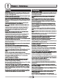 2
2
-
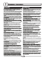 3
3
-
 4
4
-
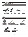 5
5
-
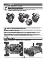 6
6
-
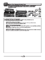 7
7
-
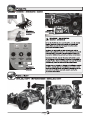 8
8
-
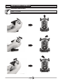 9
9
-
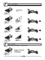 10
10
-
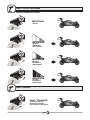 11
11
-
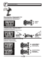 12
12
-
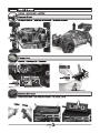 13
13
-
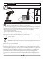 14
14
-
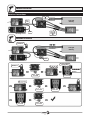 15
15
-
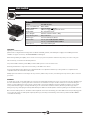 16
16
-
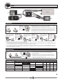 17
17
-
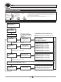 18
18
-
 19
19
-
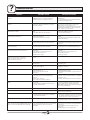 20
20
-
 21
21
-
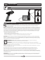 22
22
-
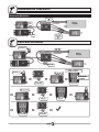 23
23
-
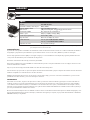 24
24
-
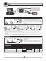 25
25
-
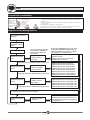 26
26
-
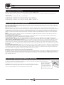 27
27
-
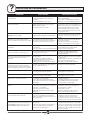 28
28
-
 29
29
-
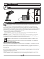 30
30
-
 31
31
-
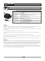 32
32
-
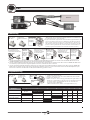 33
33
-
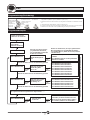 34
34
-
 35
35
-
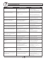 36
36
-
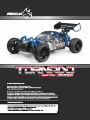 37
37
-
 38
38
-
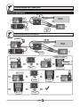 39
39
-
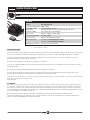 40
40
-
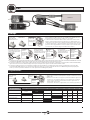 41
41
-
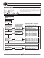 42
42
-
 43
43
-
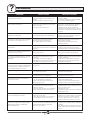 44
44
-
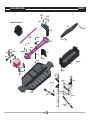 45
45
-
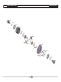 46
46
-
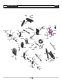 47
47
-
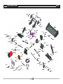 48
48
-
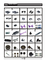 49
49
-
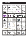 50
50
-
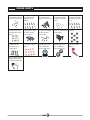 51
51
-
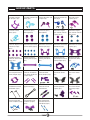 52
52
-
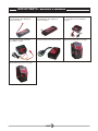 53
53
-
 54
54


Redcat Racing RER16019 El manual del propietario
- Categoría
- Juguetes a control remoto
- Tipo
- El manual del propietario
En otros idiomas
Documentos relacionados


Otros documentos
-
REDCAT GEN8 SCOUT II El manual del propietario
-
-
-
-
 Hobbytech NXT SPIRIT Manual de usuario
-
RC4WD RC4ZRTR0061 El manual del propietario
-
Maverick DesertWolf 1/8th RTR Brushless Buggy Manual de usuario
-
Kyosho No.30973 Scorpion XXL VE Manual de usuario
