LG LSCG366ST/01 Guía de instalación
- Categoría
- Cocinas
- Tipo
- Guía de instalación

INSTALLATION MANUAL
GAS COOKTOP
LSCG366ST
LSCG306ST
LSCG367ST
LSCG307ST
Please read this guide thoroughly before installation.
www.lg.com
ENGLISH
ESPAÑOL
MFL62725504_05
Copyright © 2012 - 2017 LG Electronics Inc. All Rights Reserved.

2
INSTALLATION INSTRUCTIONS
INSTALLATION SAFETY INSTRUCTIONS
BEFORE YOU BEGIN
Read these instructions completely
and carefully.
Installation of this cooktop must conform with local
codes, or in the absence of local codes, with the
National Fuel Gas Code, ANSI Z223.1/NFPA.54,
latest edition. In Canada, installation must conform
with the current Natural Gas Installation Code,
CAN/CGAB149.1 or the current Propane
Installation Code, CAN/CGA-B149.2, and with
local codes where applicable. This cooktop has
been design-certified by CSA International
according to ANSI Z21.1, latest edition and
Canadian Gas Association according to
CAN/CGA-1.1 latest edition.
As with any appliance using gas and generating
heat, there are certain safety precautions you
should follow. You will find these precautions in the
lmportant Safety Information section in your User’s
Guide. Read them carefully.
• IMPORTANT – Save these instructions for
local electrical inspector’s use.
• IMPORTANT – Observe all governing
codes and ordinances.
Note to Installer: Leave these instructions with
the appliance after installation is completed.
Note to Consumer: Keep the User’s Guide and
Installation Instructions for future reference.
NOTE: This appliance must be properly
grounded.
• The electrical diagram is in an envelope attached
to the back of the cooktop.
• Skill level – Installation of this appliance requires
basic mechanical skills.
• Proper installation is the responsibility of
theinstaller.
• Product failure due to improper installation is not
covered under the Warranty.
• Remove all tape and packaging.
• Make sure the burners are properly seated and
level.
• Take the accessory pack off of the cooktop
• Check to be sure that no cooktop parts have
come loose during shipping.

3
ENGLISH
IN THE COMMONWEALTH OF MASSACHUSETTS
PREPARING FOR INSTALLATION
FOR YOUR SAFETY
• This product must be installed by a licensed
plumber or gas fitter.
• When using ball type gas shut-off valves, they shall
be the T-handle type.
• A flexible gas connector, when used, must not
exceed 3 feet in length.
INSTALLATION INSTRUCTIONS
READ ALL INSTRUCTIONS BEFORE INSTALLATION
WARNING:
If the information in
this manual is not followed exactly, a fire or
explosion may result causing property damage,
personal injury or death.
– Do not store or use combustible materials,
gasoline or other flammable vapors and
liquids in the vicinity of this or any other
appliance.
WHAT TO DO IF YOU SMELL GAS
• Do not try to light any appliance.
• Do not touch any electrical switches,
• Do not use any phone in your building.
• Immediately call your gas supplier from a
neighbor′s phone. Follow the gas supplier
instructions.
• If you cannot contact your gas supplier, call
the fire department.
Installation and service must be performed by
a qualified installer, service agency or the gas
supplier.
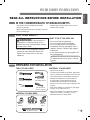
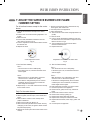
TOOLS YOU WILL NEED
MATERIALS YOU MAY NEED
MATERIALS YOU MAY NEED
• Gas line shut-off valve
• To reduce the possibility of gas leaks, apply teflon
tape or a thread compound approved for use with
LP or Natural gases to all threaded connections.
• Flexible metal appliance connector (5/8” I.D.)
A 3-foot length is recommended for ease of
installation but other lengths are acceptable.
Never use an old connector when installing a new
cooktop.
• Flare union adapter for connection to gas supply
line (3/4” or 1/2” NPT x 5/8” I.D.)
• Flare union adapter for connection to pressure
regulator on cooktop. (1/4” NPT x 1/2” I.D.)
• Liquid leak detector or soapy water.
Phillips screwdriver
Joint
Sealant
Pipe Fittings
Flexible Connector
Shut Off
Valve
Open-end or
adjustable wrench
Pipe wrench(2)
(one for support)
Flat-blade screwdriver
Pencil and ruler

4
IMPORTANT: Remove all packing material and
literature before connecting gas and electrical
supply.
• Have your cooktop installed by a qualified installer.
• Your cooktop must be electrically grounded in
accordance with local codes or, in the absence of
local codes, in accordance with the National
Electrical Code (ANSI/NFPA 70, latest edition). In
Canada, electrical grounding must be in
accordance with the current CSA C22.1 Canadian
Electrical Code Part 1 and/or local codes.
Refer to 3. Electrical Connections, in this manual.
• Be sure the wall coverings around the cooktop can
withstand heat generated by the cooktop up to
200 °F.
• Avoid placing cabinets above the cooktop.
To minimize the hazard caused by reaching over
the open flames of operating burners, install a
ventilation hood over the cooktop that projects
forward at least 5” beyond the front of the cabinets.
INSTALLATION SAFETY INSTRUCTIONS
INSTALLATION INSTRUCTIONS
This is the safety alert symbol. This symbol alerts you to potential hazards that can kill
or hurt you and others. All safety messages will follow the safety alert symbol and either
the word “ WARNING” or “CAUTION”.
BEFORE YOU BEGIN
Remove all tape and packing materials before using the cooktop. Dispose all plastic bags after
unpacking the cooktop. Never allow children to play with packing materials.
IMPORTANT SAFETY INSTRUCTIONS
Read these instructions completely and carefully. Improper installation, adjustment, alteration,
service or maintenance can cause injury or property damage.
For assistance or additional information, consult a qualified installer, service agency, manufacturer
(dealer) or your gas supplier.
Never reuse old flexible connectors. The use of old flexible connectors can cause gas leaks and
personal injury. Always use NEW flexible connectors when installing a gas appliance.
This symbol will alert you to hazards or unsafe practices which could
cause serious bodily harm or death.
WARNING
This symbol will alert you to hazards or unsafe practices which could
cause bodily injury or property damage.
CAUTION

5
ENGLISH
INSTALLATION INSTRUCTIONS
• The ventilating hood must be constructed of sheet
metal not less than 0.0122” thick. Install above the
cooktop with a clearance of not less than 1/4”
between the hood and the underside of the
combustible material or metal cabinet. The hood
must be at least as wide as the appliance and
centered over the appliance. Clearance between
the cooking surface and the ventilation hood
surface MUST NEVER BE LESS THAN 24
INCHES.
EXCEPTION: Installation of a listed microwave
oven or cooking appliance over the cooktop shall
conform to the installation instructions packed with
that appliance.
• If cabinets are located above the cooktop, allow a
minimum clearance of 30” between the cooking
surface and the bottom of unprotected cabinets.
• If a 30” clearance between cooking surface and
overhead combustible material or metal cabinets
cannot be maintained, protect the underside of the
cabinets above the cooktop with not less than 1/4”
insulating millboard covered with sheet metal not
less than 0.0122” thick. Clearance between the
cooking surface and protected cabinets MUST
NEVER BE LESS THAN 24 INCHES.
• The vertical distance from the plane of the cooking
surface to the bottom of adjacent overhead
cabinets extending closer than 1” to the plane of
the cooktop sides must not be less than 18”. (See
the Dimensions and Clearances illustration in this
manual.)
• Do not abstruct the combustion or ventilation air.
• Leak testing of the appliance shall be conducted
according to the manufacturer’s instructions.
CAUTION: Items of interest to
children should not be placed in cabinets above
the cooktop.
- children climbing on the cooktop to reach items
could be seriously injured.
WARNING: This appliance must
not be installed with a ventilation system that
blows air downward toward the cooktop. This
type of ventilation system may cause ignition
and combustion problems with the gas cooking
appliance resulting in personal injury or unintended
operation.
INSTALLATION SAFETY INSTRUCTIONS
(continued)

6
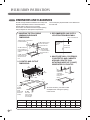
Provide enough clearances between the cooktop and
adjacent combustible surfaces. These dimensions
must be met for safe use of your cooktop.
The location of the electrical outlet and pipe opening
may be adjusted to meet specific requirements.
The cooktop may be placed with 2 3/4” clearance to
the back wall.
DIMENSIONS AND CLEARANCES
INSTALLATION INSTRUCTIONS
A
A
C
L
1. MAINTAIN THE FOLLOWING
MINIMUM CLEARANCE
DIMENSIONS
3. RECOMMENDED GAS SUPPLY
LOCATION FROM BACKWALL
4. MAKE SURE WALL COVERINGS,
COUNTERTOP AND CABINETS
AROUND COOKTOP CAN
WITHSTAND HEAT(UP TO 200℉)
GENERATED BY COOKTOP
2. COOKTOP AND CUTOUT
DIMENSIONS
13˝MAX. Depth of unprotected
overhead cabinets
A˝ MIN. clearance from
cutout to side wall on
the right of the unit
18˝ MIN. height
from countertop
to nearest cabinet
on either side of
unit
30˝ MIN. clearance
from countertop to
unprotected overhead
surface
A˝ MIN. clearance
from cutout to side
wall on the left of
unit.
L″ MIN.
Between
cutout
and the wall
behind the
cooktop
K″ MIN.
From front
edge of cutout
and front edge
of countertop
Recommended
gas supply
location
1” Min. From Backwall
From Cutout
Center Line
To ensure accuracy, it is best to make
a template when cutting the opening
in the counter
C
width
H
width cut
L
K
D
depth
B″MIN
J
depth cut
G
depth
E
height
F
width
MODEL A B C D E F G H J K L
30″ Cooktop 11
13
/
16
″ 30″ 30″ 21
11
/
16
″ 3
3
/
4
″ 28
1
/
4
″ 19
3
/
8
″ 28
1
/
2
″ 19
11
/
16
″ 1
5
/
8
″ 2
3
/
4
″
36″ Cooktop 11
13
/
16
″ 36″ 36″ 21
11
/
16
″ 3
3
/
4
″ 33
5
/
8
″ 19
3
/
8
″ 33
15
/
16
″ 19
11
/
16
″ 1
5
/
8
″ 2
3
/
4
″
Wall covering ,
cabinets and
counterto p
must withstan d
heat up to
200°F

7
ENGLISH
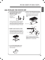
INSTALLING THE COOKTOP UNIT
INSTALLATION INSTRUCTIONS
1. LOCATE ELECTRICAL OUTLET
AND GAS SHUT-OFF VALVE
BENEATH CABINET
4. INSTALL THE RETAINER BRACKETS
Install the retainer brackets to the bottom
of the cooktop unit. then snug the bolts
against the bottom of the countertop as
shown
2. INSERT COOKTOP INTO CUTOUT
Install a manual shut-off valve in the gas line
in an easily accessible location outside the
cooktop. Be sure you know how and where to
shut off the gas supply to the cooktop. Install
the electrical outlet 12˝ below the countertop.
3. LOCATE RETAINER BRACKETS
Remove the retainer brackets from the
literature package.
NEVER RE-USE
OLD FLEX
CONNECTORS.
Install a manual shut-off valve in the gas line
in an easily accessible location outside the
cooktop. Be sure you know how and where to
shut off the gas supply to the cooktop. Install
the electrical outlet 12˝ below the countertop.
Electrical
outlet 12˝
below
countertop
Shut-Off
valve
Retainer brackets
Cooktop
Screw
Countertop
Retainer brackets
NOTE: The retainer brackets MUST be
installed to meet local codes or, in their
absence, with the National Electrical Code
ANSI/NFPA No. 70, latest edition.

8
This cooktop is designed to operate at a pressure of
5” of water column on natural gas or 10” of water
column on LP, propane or butane gas.
Make sure you are supplying your cooktop with the
type of gas for which it is designed.
This cooktop is convertible for use on natural or
propane gas. When using this cooktop on LP gas,
conversion must be made by a qualified LP installer
before attempting to operate the cooktop on that gas.
For correct operation, the pressure of natural gas
supplied to the regulator should be between 5” and
13” of water column.
For LP gas, the pressure supplied must be between
10” and 13” of water column.
When checking for correct operation of the regulator,
the inlet pressure must be at least 1” more than the
operating -manifold- pressure as given above.
The pressure regulator located at the inlet of the
cooktop manifold must remain in the supply line
regardless of whether natural or LP gas is being
used.
A flexible metal appliance connector used to connect
the cooktop to the gas supply line must have an I.D.
of 5/8” and can be 3 feet max. in length for easy
installation. In Canada, flexible connectors should be
single wall metal connectors less than 6 feet in
length.
1. PROVIDE ADEQUATE GAS SUPPLY
INSTALLATION INSTRUCTIONS
Shut off the main gas supply valve before removing
the old cooktop and leave it off until the new hook-up
has been completed. Don’t forget to relight the pilot on
other gas appliances when you turn the gas back on.
Because hard piping restricts movement of the
cooktop, the use of a CSA International-certified
flexible metal appliance connector is recommended
unless local codes require a hard-piped connection.
Never reuse an old connector when installing a new
cooktop. If the hard piping method is used, you must
carefully align the pipe; the cooktop cannot be
moved after the connection is made.
To prevent gas leaks, put pipe joint compound on, all
male -external- pipe threads.
1
Install a manual gas line shut-off valve in the gas
line in an easily accessed location outside of the
cooktop. Be sure everyone operating the cooktop
knows where and how to shut off the gas supply
to the cooktop.
2
Install male 1/2” flare union adapter to the 1/2”
NPT internal thread at inlet of pressure regulator.
Use a backup wrench on the pressure regulator
fitting to prevent damage.
3
Install male 1/2” or 3/4” flare union adapter to the
NPT internal thread of the manual shut-off valve,
taking care to back-up the shut-off valve to keep
it from turning.
4
Connect a flexible metal connector to the adapter
on the cooktop. Position the cooktop to permit
connection at the shut-off valve.
5
When all connections have been made, be sure
all cooktop controls are in the off position and
turn on the main gas supply valve.
Check for gas leaks by using manometer.
If a manometer is not available, turn the gas
supply on to the cooktop on and use a liquid leak
detector at all joints and connections to check for
leaks.
Tighten all connections, if necessary, to prevent
gas leakage in the cooktop or supply line.
WARNING!:
DO NOT USE A FLAME TO CHECK FOR GAS LEAKS.
Disconnect the cooktop and its individual shut-off
valve from the gas supply piping system during any
pressure testing of that system at test pressures
more than 1/2 psig(3.5kPa).
Isolate the cooktop from the gas supply piping
system by closing its individual shut-off valve during
any pressure testing of the gas supply system at test
pressures equal to or less than 1/2 psig(3.5kPa)
2. CONNECT THE COOKTOP TO GAS

9
ENGLISH
INSTALLATION INSTRUCTIONS
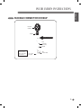
FLEXIBLE CONNECTOR HOOKUP
Pressure
regulator
Installer: Inform the
consumer of the
location of the gas
shut-off valve.
1/2” or 3/4”
Gas pipe
Flex
connector
(6 ft. max.)
Gas Flow into Range
Adapter
Gas
shut-off valve
Adapter

10
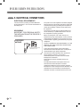
ELECTRICAL REQUIREMENTS
120 Volt, 60 Hertz, properly grounded dedicated
circuit protected by a 15 A or 20 A circuit breaker or
time delay fuse.
GROUNDING
IMPORTANT: FOR PERSONAL SAFETY,
THIS APPLIANCE MUST BE PROPERLY
GROUNDED.
PREFERRED
METHOD
Ensure proper ground
exists before use
The power cord of this appliance should be equipped
with a three-prong (grounding) plug which mates with
a standard three-prong grounding wall receptacle to
reduce the possibility of electric shock hazard from
this appliance.
The customer should have the wall receptacle and
circuit checked by a qualified technician to be sure
the receptacle is properly grounded.
When connecting the cord of this cooktop to a
standard two-prong wall receptacle, it is the personal
responsibility and obligation of the customer to have
it replaced with a properly grounded three-prong wall
receptacle.
DO NOT, UNDER ANY CIRCUMSTANCES, CUT OR
REMOVE THE THIRD (GROUND) PRONG FROM
THE POWER CORD.
A word about Ground Fault Circuit Interrupters –
Ground Fault Circuit Interrupters are not required or
recommended for gas range receptacles.
Ground Fault Circuit Interrupters are devices that
sense leakage of current in a circuit and
automatically switch off power when a threshold
leakage level is detected.
These devices must be manually reset by the
customer.
The National Electrical Code requires the use of
Ground Fault Circuit Interrupters in kitchen
receptacles installed to serve countertop surfaces.
Performance of the cooktop will not be affected if it is
operated from a Ground Fault Circuit Interrupters
protected circuit but occasional nuisance can occur.
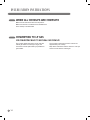
3. ELECTRICAL CONNECTIONS
INSTALLATION INSTRUCTIONS

11
ENGLISH
CAUTION
The customer should have the circuit checked by a
qualified technician to make sure the receptacle is
correctly grounded.
DO NOT use an adapter plug because disconnecting
of the power cord places undue strain on the adapter
and causes eventual failure of the adapter ground
terminal.
The customer must have the two-prong wall
receptacle replaced with a three-prong (grounding)
receptacle by a qualified technician before using this
cooktop.
The installation of appliances designed for mobile
home installation should conform with the
Manufactured Home Construction and Safety
Standard, Title 24 CFR, Part 3280 (formerly the
Federal Standard for Mobile Home Construction and
Safety, Title 24, HUD, Part 280) or, when such
standard is not applicable, the Standard for
Manufactured Home Installations, latest edition
(Manufactured Home Sites, Communities and Set-
Ups), ANSI A225.1, latest edition, or with local
codes. In Canada, mobile home installation must
comply with the current CAN/CSA Z240/MH Mobile
Home Installation Code
3. ELECTRICAL CONNECTIONS
(continued)
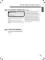
INSTALLATION INSTRUCTIONS
Seal any openings in the wall behind the cooktop
and in the floor of the cabinet when hookups are
completed.
4. SEAL THE OPENINGS

12
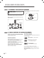
CAUTION
DO NOT operate the burners without all parts in
place.
Place the burner caps and heads on the cooktop.
Make sure that the caps and heads are placed in the
correct locations.
Small burner
head and cap
Lrage burner
head and cap
Medium burner
head and cap
Extra large burner (Center)
head and cap
Make sure the hole in the burner head is positioned
over the electrode.
Hole
Electrode
5. ASSEMBLE THE SURFACE BURNERS
INSTALLATION INSTRUCTIONS
Operation of all cooktop burners should be checked
after the COOKTOP and gas supply lines have been
carefully checked for leaks.
ELECTRIC IGNITION
Select a top burner knob, push down and then turn
counterclockwise to the “LITE” position.
You can hear a clicking sound indicating proper
operation of the spark module.
Once the air has been purged from the supply lines,
burner should ignite within 4 seconds.
After burner ignites, rotate knob out of the “LITE”
position. Try each burner in succession until all
burners have been checked.
ELECTRIC IGNITION
The combustion quality of burner flames needs to be
confirmed visually.
A Yellow flames — Call for service
B Yellow tips on outer cones
— It is normal for LP gas
C Soft blue flames
— It is normal for natural gas
If burner flames look like A, call for service.
B or C is normal burner flames, depending on the
type of gas you use.
With LP gas, some yellow tipping on outer cones is
normal.
6. CHECK IGNITION OF SURFACE BURNERS

13
ENGLISH
For all surface burners except for the center
burner
1. Light all surface burners except for the center
burner.
2. Turn the knob on the burner being adjusted to LO
(LOW).
3. Remove knob.
4. Insert a small, flat bladed screwdriver into the
valve stem as shown in Fig.2.
5. Turn the adjustment screw until the flame reaches
the desired size.
6. Replace the knob.
Center adjustment screw
Fig. 2
7. Test The Flame Stability.
Test 1 :
• Turn the knob from HI to LOW quickly.
• lf the flame goes out, increase the flame size a
nd test again.
Test 2 :
• With the burner on a LOW setting, open and
close the oven or cabinet door quickly.
• If the flame is extinguished by the air currents
created by the door movement, increase the
flame height and test again.
8. Repeat steps 1 - 6 for each surface burner except
for the center burner.
Only For the center burner
1. Disconnect power to appliance.
2. Remove grates, burners caps, burner heads and
knobs.
3. Remove all the screws on the cooktop with a
philips screwdriver.
4. Remove the cooktop by lifting it up.
5. Remove LED lamp module of the center valve by
unclipping. In this case, the ignition switch should
be positioned properly.
6. Replace the cooktop and secure the screws of the
cooktop.
7. Position center burner head, center burner cap,
center grate, and center knob.
8. Connect power to the appliance.
9. Light center burner.
10. Turn the knob on the burner being adjusted to LO
(LOW).
11. Remove knob.
12. Using a small, flat bladed screwdriver insert into
the hole next to the valve stem to adjust the outer
flame as shown in Fig.3.
13. Turn the adjustment screw until the flame
reaches the desired size.
14. Replace the knob.
Adjustment screw next to the valve shaft
Fig. 3
15. Test The Flame Stability.
Test 1 :
• Turn the knob from HI to LOW quickly.
• If the flame goes out, increase the flame size
and test again.
Test 2 :
• With the burner on a LOW setting, open and
close the oven or cabinet door quickly.
• If the flame is extinguished by the air currents
created by the door movement, increase the
flame height and test again.
16. After setting the low flame, turn off the burner.
17. Disconnect power to the appliance.
18. Remove knob, grate, burner cap, and burner
head.
19. Remove all screws from the cooktop.
20. Remove the cooktop by lifting up.
21. Replace the center LED lamp module.
22. Replace the cooktop and secure all screws.
23. Replace burner heads, burner caps, grates and
knobs.
24. Connect power to appliance.
7. ADJUST THE SURFACE BURNER LOW FLAME
(SIMMER) SETTING
INSTALLATION INSTRUCTIONS

14
Make sure all controls are left in the off position.
Make sure the flow of combustion and ventilation air
to the cooktop is unobstructed.
WHEN ALL HOOKUPS ARE COMPLETE
INSTALLATION INSTRUCTIONS
This cooktop leaves the factory set for use with
natural gas. When converting to LP gas, the
conversion must be performed by a qualified LP
gas installer.
The conversion instructions and LP orifices are
supplied with your cooktop.
Keep these instructions and the orifices in case you
want to convert back to natural gas.
CONVERTING TO LP GAS
(OR CONVERTING BACK TO NATURAL GAS FROM LP)

MANUAL DE INSTALACIÓN
COCINA DE GAS
Por favor lea esta guía completamente antes de la instalación.
P/No.: MFL62725504
www.lg.com
ESPAÑOL
LSCG366ST
LSCG306ST
LSCG367ST
LSCG307ST
Copyright © 2012 - 2017 LG Electronics Inc. Todos los Derechos Reservados.

2
INSTRUCCIONES DE INSTALACIÓN
INSTRUCCIONES DE SEGURIDAD DURANTE LA
INSTALACIÓN ANTES DE COMENZAR

3
ESPAÑOL
EN EL ESTADO DE MASSACHUSETTS
PREPARATIVOS PARA LA INSTALACIÓN
PARA SU SEGURIDAD
• Este producto debe ser instalado por un fontanero
o técnico de gas autorizado.
• Al usar válvulas de corte de gas tipo esféricas,
deberá ser del tipo llave en T.
• Al usar un conector de gas flexible, no debe
exceder los 3 pies de longitud.
INSTRUCCIONES DE INSTALACIÓN
LEA TODAS LAS INSTRUCCIONES ANTES DE
REALIZAR LA INSTALACIÓN
ADVERTENCIA:
Si la
información contenida en este manual no se
cumple expresamente, podría ocasionarse un
incendio o explosión, provocando daños a la
propiedad, lesiones personales o incluso la
muerte.
– No almacene ni use materiales inflamables,
gasolina u otros vapores y líquidos
inflamables cerca de éste u otros
electrodomésticos.
QUÉ HACER SI PERCIBE OLOR A GAS
• No intente prender ningún electrodoméstico.
• No toque ningun interruptor eléctrico.
• Llame inmediatamente a su distribuidor de
gas desde el teléfono de un vecino. Siga las
instrucciones proporcionadas por el
distribuidor de gas.
• Si le es imposible contactar con su
distribuidor de gas, llame a los bomberos.
La instalación y mantenimiento deben
realizarlas un instalador cualificado, empresa
de servicios o el distribuidor de gas
HERRAMIENTAS QUE NECESITARÁ
MATERIALES QUE PODRÍA NECESITAR
MATERIALES QUE PODRÍA NECESITAR
• Válvula de cierre de la toma de gas
• Para reducir la posibilidad de que se produzca un
escape de gas, aplique cinta de teflón o un
compuesto para roscas aprobado para su uso con
gas LP o natural para todas las conexiones
roscadas.
• Conector de electrodoméstico de metal flexible
(5/8” I.D.).
Se recomienda una longitud de 3 pies para hacer
más fácil la instalación pero son aceptables otras
longitudes.
No use nunca un conector viejo al instalar una
nueva cocina.
• Adaptador de unión abocinada para la conexión a
toma de suministro de gas
(3/4” ó 1/2” NPT x 1/2” I.D.)
• Adaptador de unión abocinada para la conexión al
regulador de presión en la cocina.
(1/2” NPT x 1/2” I.D.)
• Detector de fugas líquido o agua jabonosa.
• Perno de fijación o anclaje de manguito 1/2” O.D.
(sólo para pisos de hormigón).
Destornillador Phillips
Sellador
de juntas
Acoples
de tubería
Conector flexible
Válvula
de cierre
Llave de boca
o ajustable
Llave para tubo (2)
(una por soporte)
Destornillador de
cabeza plana
Lápiz y regla

4
IMPORTANTE: Retire todo el material de embalaje y
los documentos del horno antes de conectarlo al
suministro de gas y eléctrico.
• Haga que instale su cocina un instalador
cualificado.
• Su cocina debe quedar conectada correctamente a
tierra según los códigos locales o, en ausencia de
los mismos, según el Código eléctrico nacional
(ANSI/NFPA 70, edición más reciente).
En Canadá, la conexión a tierra debe cumplir con
la Sección 1 del Código eléctrico canadiense CSA
C22.1 actual y/o con los códigos locales.
Examine la sección Conexiones eléctricas en este
manual.
• Asegúrese de que todas las paredes que rodean a
la cocina pueden resistir un calor generado por la
cocina de hasta 200 °F. (93 °C)
• Evite la instalación de armarios sobre la cocina.
Para reducir el riesgo ocasionado por extender el
brazo sobre las llamas abiertas de los quemadores
prendidos, instale un extractor de ventilación sobre
la cocina que se proyecte al menos 5” más allá de
la parte frontal de los armarios.
INSTRUCCIONES DE SEGURIDAD DURANTE LA
INSTALACIÓN
INSTRUCCIONES DE INSTALACIÓN
Este es el símbolo de alerta de seguridad.
Este símbolo alerta de peligros potenciales que podrían provocar lesiones personales o
a terceros, e incluso la muerte. Todos los mensajes de seguridad están precedidos por
un símbolo de advertencia, además de la palabra “ADVERTENCIA” o “PRECAUCIÓN”.
Estas palabras significan:
ANTES DE COMENZAR
Retire todas las cintas y materiales de embalaje antes de usar el horno.
Deseche todas las bolsas de plástico tras desembalar la cocina. Nunca permita que los niños
jueguen con los materiales de embalaje.
INSTRUCCIONES IMPORTANTES DE SEGURIDAD
Lea estas instrucciones completa y atentamente. Una instalación, ajuste, alteración, servicio o
mantenimiento incorrecto, puede ocasionar lesiones personales o daños a la propiedad.
Examine este manual. Para obtener asistencia o información adicional, consulte a un instalador,
empresa de servicios, productor(distribuidor) o proveedor de gas cualificado.
No vuelva a usar nunca conectores flexibles viejos. El uso de conectores flexibles viejos puede
ocasionar fugas de gas y lesiones personales.
Use siempre conectores flexibles NUEVOS al instalar un electrodoméstico de gas.
Este símbolo alerta de peligros o prácticas no seguras que
podrían ocasionar lesiones físicas graves o incluso la muerte.
ADVERTENCIA
Este símbolo alerta de peligros o prácticas no seguras que
podrían ocasionar lesiones físicas o daños a la propiedad.
PRECAUCIÓN

5
ESPAÑOL
INSTRUCCIONES DE INSTALACIÓN
• El extractor de ventilación debe estar compuesto
por láminas metálicas con un grosor no inferior a
0.0122”. Instalar sobre la cocina dejando un
espacio libre no inferior a ¼” entre el extractor y la
cara inferior del material combustible o armario de
metal.
El extractor debe disponer del ancho del
electrodoméstico al menos y estar centrado sobre
el mismo.
El espacio libre entre la superficie de la cocina y la
del extractor de ventilación NUNCA DEBE SER
INFERIOR A 24 PULGADAS.
EXCEPCIÓN: La instalación de un horno
microondas o electrodoméstico de cocina
catalogado sobre su cocina cumplirá las
instrucciones de instalación anexas al
electrodoméstico.
• Si hay armarios instalados sobre la cocina, permita
un espacio mínimo de 30” entre la superficie de la
cocina y la base de los armarios sin protección.
• Si resulta imposible obtener 30” de espacio libre
entre la superficie de la cocina y el material
combustible o el armario metálico superior, proteja
la parte inferior del armario situado sobre la cocina
mediante no menos de 1/4” de cartón de
aislamiento cubierto con lámina metálica con un
espesor no inferior a 0.0122”.
El espacio libre entre la superficie de la cocina y los
armarios protegidos NUNCA DEBE SER
INFERIOR A 24 PULGADAS.
• La distancia vertical desde el plano de la superficie
de cocción hasta la base de los armarios
superiores contiguos que se extiendan menos de
1” del plano de los laterales de la cocina, no debe
ser inferior a 18”. (Examine la ilustración
Dimensiones y espacios libres en este manual).
• No obstruir el flujo de aire de combustión y
ventilación.
• Las pruebas de fugas de la aplicación se llevará a
cabo de acuerdo con las instrucciones del
fabricante.
PRECAUCIÓN: los objetos de
interés para los niños no deben guardarse en los
armarios situados sobre la cocina.
- Si los niños se suben a la cocina para alcanzar
los objetos podrían sufrir lesiones graves.
ADVERTENCIA: Este equipo
no se debe instalar con un sistema de ventilación
que dirija el aire hacia abajo, hacia la estufa.
Este tipo de sistema de ventilación puede causar
problemas de encendido y combustión con la
estufa a gas, que resulten en daños personales o
de operación no intencional.
INSTRUCCIONES DE SEGURIDAD DURANTE LA
INSTALACIÓN
(continuación)

6
Permita los espacios libres adecuados entre la
cocina y las superficies combustibles adyacentes.
Deben respetarse estas dimensiones para usar su
cocina de forma segura.
El emplazamiento de las tomas eléctricas y las
acometidas de tubería puede ajustarse para cumplir
exigencias específicas.
La cocina puede colocarse con 0” de espacio libre
(a ras) hasta la pared posterior.
DIMENSIONES Y ESPACIOS LIBRES
INSTRUCCIONES DE INSTALACIÓN
A
A
C
L
1. MANTENGA LAS SIGUIENTES
DIMENSIONES DE ESPACIO LIBRE
3. LOCALIZACIÓN DEL SUMINISTRO
DE GAS RECOMENDADA DESDE
LA PARED POSTERIOR
4. ASEGÚRESE DE QUE EL
RECUBRIMIENTO DE LA PARED, LA
ENCIMERA Y LOS ARMARIOS
SITUADOS ENTORNO A LA COCINA
PUEDAN RESISTIR EL CALOR
GENERADO POR LA COCINA
(HASTA 200ºF)
2. DIMENSIONES DE LA COCINA
Y EL CORTE
Máx. 13˝ de profundidad
de los armarios superiores
sin protección.
Mín. A” de espacio libre
desde el corte a la pared
lateral situada a la derecha
de la unidad.
Mín. 182 de altura desde
la encimera al armario
más cercano a ambos
lados de la unidad.
Mín. 30” de espacio libre
desde la encimera hasta
la superficie superior
sin protección.
Mín. A” de espacio
libre desde el corte a la
pared lateral situada a la
izquierda de la unidad.
Mín. L”
Entre el corte
y la pared
posterior
de la cocina.
Mín. K”
Desde el borde
frontal del corte
y de la encimera.
Localización del
suministro de gas
recomendada
Mín. 1” desde la
pared posterior
Desde la línea
central de corte
Para garantizar la precisión, la mejor opción
es realizar una plantilla al cortar el hueco de
instalación en la encimera.
C
ancho
H
ancho del corte
L
K
D
profundidad
Mín. B"
J
profundidad del corte
G
profundidad
E
alto
F
ancho
MODELO A B C D E F G H J K L
30″ Cocina 11
13
/
16
″ 30″ 30″ 21
11
/
16
″ 3
3
/
4
″ 28
1
/
4
″ 19
3
/
8
″ 28
1
/
2
″ 19
11
/
16
″ 1
5
/
8
″ 2
3
/
4
″
36″ Cocina 11
13
/
16
″ 36″ 36″ 21
11
/
16
″ 3
3
/
4
″ 33
5
/
8
″ 19
3
/
8
″ 33
15
/
16
″ 19
11
/
16
″ 1
5
/
8
″ 2
3
/
4
″
El recubrimiento de la
pared, los armarios
y la encimera deben
resistir hasta
200°F.

7
ESPAÑOL
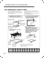
INSTALACIÓN DE LA UNIDAD DE LA COCINA
INSTRUCCIONES DE INSTALACIÓN
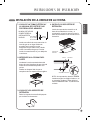
1. LOCALICE LA TOMA ELÉCTRICA Y
LA VÁLVULA DE CORTE DE GAS
POR DEBAJO DEL ARMARIO.
4. INSTALE LOS SOPORTES DE
RETENCIÓN
Instale los soportes de retención en la
base de la unidad de la cocina y, a
continuación, ajuste los pernos contra la
base de la encimera como se indica en la
ilustración.
2. INTRODUZCA LA COCINA EN EL
CORTE
Introduzca la cocina centrada dentro del
hueco de corte. Asegúrese de que el borde
frontal de la encimera sea paralelo a la
cocina.
Realice un chequeo final de que se
cumplen todos los espacios libres exigidos.
3. LOCALICE LOS SOPORTES DE
RETENCIÓN
Retire los soportes de retención del paquete
que contiene los documentos.
NUNCA USE VIEJOS
CONECTORES AL
INSTALAR ESTA
UNIDAD.
Instale una válvula de corte manual en la
toma de gas en un lugar fácilmente
accesible por fuera de la cocina.
Asegúrese de que sabe cómo y dónde
cortar el suministro de gas a la cocina.
Instale la toma eléctrica 12” por debajo de
la encimera.
Toma eléctrica
12” por debajo
de la encimera
Válvula
de cierre
Soportes de
retención
Cocina
Perno
Encimera
Soportes de retención
NOTA: los soportes de retención DEBEN
instalarse según los códigos locales o, en
su ausencia, según el Código eléctrico
nacional ANSI/NFPA No. 70, edición más
reciente.

8
Su cocina está diseñada para funcionar a una
presión de 5” de columna de agua sobre gas natural
o, en diseños para gas LP (propano o butano), 10”
de columna de agua.
Asegúrese de suministrar a su cocina el tipo de gas
para el que fue diseñada.
Esta cocina se puede adaptar para usar gas natural
o propano. Si decide usar esta cocina con gas LP, la
adaptación debe realizarla un instalador de gas LP
cualificado antes de intentar poner en
funcionamiento la cocina con este gas.
Para un funcionamiento correcto, la presión del gas
natural suministrado al regulador debe estar entre 5”
y 13” de columna de agua.
Para gas LP, la presión de suministro debe estar
entre 10” y 13” de columna de agua.
Al chequear el correcto funcionamiento del
regulador, la presión de entrada debe ser al menos
1” mayor que la presión operativa (de admisión)
indicada anteriormente.
El regulador de presión situado en la entrada del
distribuidor de la cocina debe conservarse en la
toma de suministro independientemente de si va a
usar gas natural o LP.
Un conector de electrodoméstico de metal flexible
usado para conectar la cocina a la toma de suministro
de gas debe disponer de un I.D. de 5/8” y puede tener
3 pies de longitud para facilitar la instalación.
En Canadá, los conectores flexibles deben ser
conectores metálicos de pared simple con una
longitud no superior a los 6 pies.
1. PROPORCIONE EL SUMINISTRO DE GAS ADECUADO
INSTRUCCIONES DE INSTALACIÓN
Interrumpa la válvula del suministro principal de gas
antes de desconectar la antigua cocina y déjela
desactivada hasta terminar la nueva conexión.
No olvide volver a prender el piloto del resto de los
electrodomésticos de gas cuando vuelva a abrir el
suministro.
Debido a los movimientos restrictivos de las
canalizaciones rígidas de la cocina, se recomienda el
uso de un conector de electrodoméstico de metal
flexible certificado a menos que los códigos locales
exijan una conexión mediante canalización rígida.
No use nunca un conector viejo al instalar una nueva
cocina. Si se usa el método de la canalización rígida,
debe alinear cuidadosamente la tubería; la cocina no
puede moverse una vez realizada la conexión.
Para prevenir fugas de gas, aplique compuesto para
empalmes de tubería o envuelva con cinta de teflón
todas las roscas macho (externas) de las tuberías.
1
Instale una válvula de corte manual en la toma
de gas en un lugar fácilmente accesible por
fuera de la cocina. Asegúrese de que cualquier
persona que use la cocina sepa dónde y cómo
cortar el suministro de gas de la cocina.
2
Instale el adaptador de unión abocinada de ½” a
la rosca interna NPT de ½” en la entrada del
regulador Use una llave de seguridad en el
ajuste del regulador para evitar daños. Al instalar
la cocina desde la parte frontal, retire el codo de
90º para facilitar la instalación.
3
Instale el adaptador de unión abocinada macho
de ½” ó ¾” en la rosca interna NPT de la válvula
de corte manual, teniendo cuidado de asegurar
la válvula de corte para evitar que gire.
4
Conecte el conector de electrodoméstico de
metal flexible al adaptador de la cocina.
Coloque la cocina de tal forma que permita la
conexión en la válvula de corte.
5
Cuando se hayan realizado todas las
conexiones, asegúrese de que todos los
controles de la cocina se encuentren en su
posición de apagado y abra la válvula de
suministro principal de gas.
Chequee el sistema en búsqueda de fugas con el
manómetro. Si no dispone de un manómetro,
abra el suministro de gas de la cocina y use un
detector de fugas líquido en todas las juntas y
conexiones en busca de fugas. Apriete todas las
conexiones si fuese necesario para prevenir
fugas de gas en la cocina o la toma de suministro.
ADVERTENCIA!
NO USE UNA LLAMA PARA BUSCAR FUGAS DE GAS.
Desconecte la cocina y su válvula de corte individual
del sistema de canalización de suministro de gas
durante cualquier prueba de presión del sistema
a presiones de prueba superiores al ½ psig (3,5
kPa). Aísle la cocina del sistema de canalización
de suministro de gas cerrando su válvula de corte
individual durante cualquier prueba de presión del
sistema de suministro a presiones de prueba iguales
o inferiores a ½ psig (3,5 kPa).
2. CONECTE LA COCINA AL GAS

9
ESPAÑOL
INSTRUCCIONES DE INSTALACIÓN
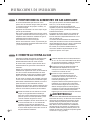
CONEXIÓN DEL CONECTOR FLEXIBLE
Regulador
de presión
Instalador: comunique al
cliente el emplazamiento
de la válvula de corte
de gas.
1/2” or 3/4”
Conducto de gas
Conector flexible
(máx. 6 pies)
Flujo de gas al horno
Adaptador
Válvula de cierre
de gas
Adaptador

10
REQUISITOS ELÉCTRICOS
120 voltios, 60 hercios, conexión a tierra adecuada,
circuito propio protegido mediante disyuntor de 15 ó
20 amperios o fusible retardador.
CONEXIÓN A TIERRA
IMPORTANTE: POR MOTIVOS DE
SEGURIDAD PERSONAL, ESTE
ELECTRODOMÉSTICO DEBE
CONECTARSE CORRECTAMENTE A
TIERRA.
MÉTODO
RECOMENDADO
Asegúrese que existe una
correcta puesta a tierra
antes de usar la unidad
El cable de alimentación de este electrodoméstico
está equipado con un toma corriente de tres clavijas
(de puesta a tierra) que coincide con una toma de
pared para tres clavijas (de puesta a tierra) y así
minimizar la posibilidad de peligro por choque
eléctrico de este electrodoméstico.
El cliente debe solicitar a un electricista que revise
su toma de pared y el circuito a fin de asegurar la
correcta puesta a tierra del toma corriente.
Si únicamente contara con un toma corriente
estándar de dos clavijas, será responsabilidad y
obligación del cliente reemplazarlo por otro de tres
clavijas con una conexión a tierra adecuada.
NO CORTE NI DESMONTE, BAJO NINGUNA
CIRCUNSTANCIA, LA TERCERA CLAVIJA (DE
CONEXIÓN A TIERRA) DEL TOMA CORRIENTE
DEL CABLE DE ALI MENTACIÓN.
Acerca de los GFCI’s: los GFCI’s no son necesarios
ni se recomiendan para tomas de pared de hornos
de gas.
Los interruptores de circuito de falla de puesta a
tierra (GFCI's) son dispositivos que detectan la fuga
de corriente en un circuito e interrumpen
automáticamente el suministro al detectar un nivel
umbral de fuga. Estos dispositivos deben ser
reiniciados manualmente por el cliente.
El Código eléctrico nacional exige el uso de GFCI's
en los toma corrientes de cocina instalados para dar
servicio a encimeras.
El rendimiento de la cocina no se verá afectado al
funcionar bajo un circuito protegido mediante un
GFCI, pero ocasionará molestias ocasionales.
3. CONEXIONES ELÉCTRICAS
INSTRUCCIONES DE INSTALACIÓN

11
ESPAÑOL
PRECAUCIÓN
El cliente debe solicitar a un electricista que revise
el circuito a fin de asegurar la correcta puesta a
tierra del toma corriente.
No use un adaptador, ya que la desconexión del
cable de alimentación provoca un estiramiento
excesivo del adaptador y puede provocar una falla
eventual del terminal de tierra del adaptador.
El cliente deberá solicitar a un electricista cualificado
que reemplace la toma de pared de dos clavijas por
una de tres (con conexión a tierra) antes de usar el
electrodoméstico.
La instalación de electrodomésticos diseñados para
instalaciones en viviendas móviles debe cumplir con
el Manufactured Home Construction and Safety
Standard, título 24 CFR, sección 3280
(antiguamente denominado Federal Standard for
Mobile Home Construction and Safety, título 24,
HUD, sección 280) o, cuando dicho estándar no sea
aplicable, con el Standard for Manufactured Home
Installations, edición más reciente (Manufactured
Home Sites, Communities and Set-Ups), ANSI
A225.1, edición más reciente o con los códigos
locales.
En Canadá, la instalación en viviendas móviles debe
cumplir con el actual CAN/CSA Z240/MH Mobile
Home Installation Code.
3. CONEXIONES ELÉCTRICAS
(continuación)
INSTRUCCIONES DE INSTALACIÓN
Selle cualquier hueco existente en la pared de la
parte posterior de la cocina y en el piso sobre el
armario al terminar las conexiones.
4. SELLE LOS HUECOS

12
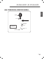
PRECAUCIÓN
No use los quemadores sin haber montado todas
sus piezas en su sitio.
Coloque las tapas y cabezas de los quemadores en
la cocina. Asegúrese de que las tapas y cabezas
estén colocados en posición correcta.
Hay una cabeza y tapa del quemador pequeño, dos
de los medianos, una grande y una extragrande.
Cabeza y tapa del
quemador pequeño
Cabeza y tapa del
que mador grande
Cabeza y tapa
del quemador
mediano
Cabeza y tapa del
quemador extra-grande
(central)
Asegúrese de colocar el hueco de la cabeza del
quemador sobre el electrodo.
Hueco
Electrodo
5. MONTE LOS FOGONES
INSTRUCCIONES DE INSTALACIÓN
Debe chequearse el funcionamiento de todos los
quemadores de la cocina y el horno tras chequear
cuidadosamente que no existen fugas en el horno ni
en las tomas de suministro de gas.
PRENDIDO ELÉCTRICO
Escoja el mando de un quemador y presiónelo y
gírelo simultáneamente a la posición “LITE”.
Podrá oír el “clic” indicativo de un correcto
funcionamiento del módulo generador de chispas.
Una vez purgado el aire de las tomas de suministro,
el quemador deberá prenderse en 4 segundos.
Tras prender el quemador, gire el mando de la
posición “LITE”. Pruebe sucesivamente cada
quemador hasta chequearlos todos.
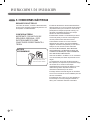
CALIDAD DE LAS LLAMAS
La calidad de la combustión de las llamas del
quemador precisa determinarse visualmente.
A. Llamas amarillas — solicite
asistencia técnica
B Puntas amarillas en los conos
exteriores — normal para gas LP
C Llamas azules suaves
— normal para gas natural
Si las llamas aparecen como se reflejan en la
ilustración A, solicite asistencia técnica.
Unas llamas normales en el quemador deberán
aparecer como se reflejan en la ilustración B o C,
dependiendo del tipo de gas que use.
Con gas LP, la presencia de ciertas puntas amarillas
en los conos exteriores se considera normal.
6. CHEQUEE EL PRENDIDO DE LOS QUEMADORES

13
ESPAÑOL
Para todos los quemadores a excepción del
central
1. Encienda todos los quemadores a excepción del
central.
2. Gire el mando del quemador que desea ajustar
hasta la posición “LO” (BAJA).
3. Extraiga el mando.
4. Introduzca un destornillador pequeño de cabeza
plana en la válvula como se muestra en la Fig.2.
5. Gire el tornillo de ajuste hasta que la llama
alcance el tamaño deseado.
6. Vuelva a colocar el mando.
Tornillo de ajuste central
Fig. 2
7. Compruebe la estabilidad de la llama.
Prueba 1:
• Gire con rapidez el mando de la posición “HI”
(alta) a “LOW” (baja).
• Si la llama se apaga, aumente el tamaño de ésta
y vuelva a realizar la prueba.
Prueba 2 :
• Con el quemador en la posición “LOW” (baja),
abra y cierre la puerta del horno con rapidez.
• Si la llama se apaga al abrir la puerta, aumente
la fuerza de ésta y realice la prueba de nuevo.
8. Repita los pasos del 1 al 6 para cada uno de los
quemadores, excepto para el central.
Sólo para el quemador central
1. Desconecte la alimentación del aparato.
2. Extraiga los mandos, las rejillas, y las cabezas y
fundas de los quemadores.
3. Extraiga todos los tornillos de la parte superior de
la cocina con un destornillador de estrella.
4. Levante la parte superior de la cocina y retírela.
5. Desenganche y retire el módulo de lámparas
LED de la válvula central. En este momento, el
interruptor de encendido debe estar en la posición
correcta.
6. Coloque la parte superior de la cocina y fíjela
mediante los tornillos.
7. Coloque el quemador central y la funda del
quemador, la rejilla del centro y el mando central.
8. Conecte la alimentación del aparato.
9. Encienda el quemador central.
10. Gire el mando del quemador que desea ajustar
hasta la posición “LO” (BAJA).
11. Extraiga el mando.
12. Introduzca un destornillador pequeño de cabeza
plana en el agujero que hay junto al vástago de
la válvula, para ajustar la llama exterior como se
muestra en la Fig. 3.
13. Gire el tornillo de ajuste hasta que la llama
alcance el tamaño deseado.
14. Vuelva a colocar el mando.
Ajuste el tornillo que hay junto al eje de la válvula
Fig. 3
15. Compruebe la estabilidad de la llama.
Prueba1 :
• Gire con rapidez el mando de la posición “HI”
(alta) a “LOW” (baja).
• Si la llama se apaga, aumente el tamaño de ésta
y vuelva a realizar la prueba.
Prueba 2 :
• Con el quemador en la posición “LOW” (baja),
abra y cierre la puerta del horno con rapidez.
• Si la llama se apaga al abrir la puerta, aumente
la fuerza de ésta y realice la prueba de nuevo.
16. Apague el quemador tras dejar la llama en la
posición baja.
17. Desconecte la alimentación del aparato.
18. Extraiga el mando, la rejilla, la funda y la cabeza
del quemador.
19. Retire todos los tornillos de la parte superior de
la cocina.
20. Levante la parte superior de la cocina y retírela.
21. Vuelva a enganchar el módulo central de
lámparas LED.
22. Coloque de nuevo la parte superior de la cocina
y fíjela mediante los tornillos.
23. Vuelva a colocar los mandos, las rejillas, y las
cabezas y fundas de los quemadores.
24. Conecte la alimentación del aparato.
7. REDUCIR LA LLAMA DEL QUEMADOR A LA POSICIÓN
BAJA (COCER A FUEGO LENTO).
INSTRUCCIONES DE INSTALACIÓN

14
Asegúrese de dejar todos los controles en la
posición de apagado.
Asegúrese de que el flujo de combustión y el aire de
ventilación al horno no estén obstruidos.
AL TERMINAR TODAS LAS CONEXIONES
INSTRUCCIONES DE INSTALACIÓN
Esta cocina viene ajustada de fábrica para su uso
con gas natural.
Si desea adaptarla para usar gas LP, la conversión
debe llevarla a cabo un instalador de gas LP
cualificado.
Las instrucciones y orificios LP de adaptación están
incluidos en su cocina.
Conserve estas instrucciones y los orificios por si
desea readaptar su cocina en el futuro para que use
gas natural.
ADAPTACIÓN A GAS LP
(O READAPTACIÓN A GAS NATURAL DE UNA INSTALACIÓN DE LP)

MEMO

MEMO

MEMO

Printed in Korea
-
 1
1
-
 2
2
-
 3
3
-
 4
4
-
 5
5
-
 6
6
-
 7
7
-
 8
8
-
 9
9
-
 10
10
-
 11
11
-
 12
12
-
 13
13
-
 14
14
-
 15
15
-
 16
16
-
 17
17
-
 18
18
-
 19
19
-
 20
20
-
 21
21
-
 22
22
-
 23
23
-
 24
24
-
 25
25
-
 26
26
-
 27
27
-
 28
28
-
 29
29
-
 30
30
-
 31
31
-
 32
32


LG LSCG366ST/01 Guía de instalación
- Categoría
- Cocinas
- Tipo
- Guía de instalación
en otros idiomas
- English: LG LSCG366ST/01 Installation guide