
IMPORTANT NOTICE – READ BEFORE INSTALLATION
Ford KV Angle Meter Stops, AV and FV Angle Valves
Installation Instructions
Read Warranty Information Below Before Installing
Refer to the Ford website (http://www.fordmeterbox.com) for additional and most
recent installation instructions and product information.
Ford KV Angle Meter Stops, AV and FV Angle Valves are inverted-key type valves. Two
bronze spring washers between the key and tee head assist in holding the tapered key
firmly in place. All valves are supplied with an O-ring at the key top to eliminate leakage.
Valves open counter-clockwise with a quarter turn action (90 degrees).
INSTRUCTIONS AND PRECAUTIONS
(1) Handle the valve carefully to avoid damage to threads, sealing surfaces and moving
parts. Keep valve free of dirt, sand, pipe chips, Teflon tape or sealants. Protect the
valve from freezing or serious damage may result. Do not drop or throw valve. Do
not use a pipe wrench.
(2) Use caution when tightening threaded connections. Use a quality sealant or Teflon
tape on tapered pipe threads. Tighten the valve with a close-fitting smooth-jawed
wrench only on the body flats provided. The use of a pipe wrench or wrenching
on surfaces other than the flats may result in body distortion and valve leakage not
covered by warranty. DO NOT INSERT A SCREWDRIVER OR OTHER OBJECT
IN THE VALVE OUTLET TO TIGHTEN - DAMAGE WILL RESULT.
(3) Ford offers Pack Joint, Grip Joint and Quick Joint style outlet connections. Make sure
to read and follow the proper (A, B, or C) instructions below that match the
compression style outlet connection supplied.
(4) When possible, flush out the service line and valve following installation.
(5) This valve is manufactured to AWWA C800 standard. If the 3/4" or 1" valve leaks
while testing service lines at pressures greater than 100 PSIG (80 PSIG for 1-1/2"
and 2" valves), open the valve, plug the outlet and test again. Use a ball valve for
higher pressures.
(6) Inverted Key Valves are not designed for frequent operation. If the valve leaks,
open and close several times to assist in reseating the key. For frequent operation
a Ball Valve is recommended.
(7) Protect valve from freezing. Freezing can damage valve and cause leaks.
(8) CONSULT PIPE OR TUBING MANUFACTURER FOR SPECIFIC INSTALLATION
REQUIREMENTS.
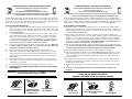
RECOMMENDED
PIPE WRENCH
DO NOT USE A
PIPE WRENCH
USE A
SMOOTH WRENCH
AND FULLY ENGAGE
WRENCH FLATS
WARNING: Do not use on gas lines. Installation on gas lines
can result in serious injury or death.
AVISO IMPORTANTE – LEER ANTES DE INSTALAR
Llaves Angulares del Medidor Ford KV, Válvulas Angulares AV y FV
Instrucciones de Instalación
Lea la Informacion de Granita Antes de Instalar
Para información de los productos e instrucciones de instalación adicionales y más recientes,
por favor visita la pagina de internet de Ford (http://www.fordmeterbox.com)
Las Llaves Angulares del Medidor Ford KV y las Válvulas Angulares AV y FV son válvulas del tipo
con llave invertida. Dos arandelas de resorte de bronce entre la llave y la cabeza T ayudan a mantener
la llave cónica en su lugar. Todas las válvulas son proveídas con un O-Ring en la tapa de la llave para
eliminar fugas. Las válvulas abren hacia la izquierda al girar un cuarto de vuelta (90 grados).
INSTRUCCIONES Y PRECAUCIONES
(1) Manejar la válvula con cuidado para evitar daño a las roscas, superficies de sellado y piezas
móviles. Mantener la válvula libre de polvo, arena, astillas del tubo, cinta Teflón o productos de
sellador. Proteger la válvula de congelamiento o puede resultar en daño severo. No dejarla caer
ni tirarla. No usar una llave de tubo.
(2) Tener cuidado cuando apretar las conexiones roscadas. Usar un producto sellador o cinta
Teflón de calidad en las roscas cónicas de la tubería. Apretar la válvula con llave de pinzas lisas
ajustadas solo en las caras proveídas. El uso de una llave de tubería o ajustar en superficies
diferentes de las señaladas caras podría resultar en distorsión del cuerpo y fuga de la válvula
no cubierta por garantía. NO INSERTAR UN DESATORNILLADOR U OTRO OBJETO EN LA
SALIDA DE LA VÁLVULA PARA APRETAR - DAÑO RESULTARA.
(3) Ford ofrece en la salida de la válvula conexiones de compresión tipo Pack Joint, Grip Joint y Quick
Joint. Por favor de asegurar de leer y seguir las instrucciones apropiadas (A, B o C) abajo que
corresponde al tipo de conexión de compresión suplido para la salida de la válvula.
(4) Cuando sea posible, limpiar la línea de servicio y la válvula después de instalarla.
(5) Esta válvula es fabricada de acuerdo con el estándar AWWA C800. Si la válvula 3/4" o 1" tiene
fugas al probar las líneas de servicio a presiones más de 100 PSIG (80 PSIG para válvulas de
1-1/2" y 2"), abrir la válvula, tapar la salida y probarla otra vez. Utilizar una válvula de bola para
presiones más altas.
(6) Las válvulas de llave invertidas no son diseñadas para operación frecuente. Si la válvula tiene
fuga, abrir y cerrar varias veces para asistir en reasentar la llave. Para operación frecuente se
recomienda una Válvula de Bola.
(7) Proteger para que la válvula no se congele. Si la válvula se congela se puede dañar y causar
fugas.
(8) Consultar con el fabricante de la tubería o cañería para requisitos específicos de
instalación.
LLAVE
RECOMENDADA
NO USAR UNA
LLAVE DE TUBO
USAR UNA LLAVE LISA Y
ENGANCHARCOMPLETAMENTE
LAS CARAS
PRECAUCION/AVISO: No usar en líneas de gas. Instalación en
líneas de gas puede resultar en
heridas y lesiones serias incluyendo muerte.

Steps for Installation
1. Make sure pipe is round, not flattened. On copper tubing use a rounding
tool, if necessary. Clean or scrape off any dirt or corrosion so that surface
is smooth.
2. The tubing should be inserted into the fitting so that the end of the tubing is
well past the rubber seal gasket. If the nut or socket appears too large for
pipe, a check should be made to be sure you are using the correct fitting or
that pipe is of proper diameter.
3. Tighten Pack Joint nut 1 to 1-1/2 turns after gasket starts to compress. If
clamp screw is not accessible, reposition by further tightening Pack Joint nut.
4. To ensure against blowout of pipe, tighten the clamp screw very securely. A
socket or box end wrench is preferable to a screwdriver. Avoid overtightening
that could distort pipe and tubing.
5. ALWAYS PRESSURE TEST FOR LEAKS BEFORE BACKFILLING.
6. CONSULT PIPE OR TUBING MANUFACTURER FOR SPECIFIC
INSTALLATION REQUIREMENTS.
PRECAUTIONS
1. Brass fittings can be damaged by improper handling. Protect threads. Avoid
loose fitting wrenches. Do not drop. Backfill and compact carefully so that
fittings are not stressed by the weight of the earth.
2. If you are unfamiliar with Pack Joint connections, a little practice and testing
in the shop before going on the job is time well spent.
3. Use Ford solid tubular metal insert stiffeners with any plastic pipe that is likely
to distort or cold flow under pressure of the Pack Joint rubber or clamp squeeze.
4. Inspect and test all joints, valves, and fittings for leaks before
backfilling. If this is impossible and when several are involved, be sure to
test system as job progresses instead of waiting until all services are
completed. Making repairs after backfilling is costly.
5. Use extra care with higher water pressures (over 100psi) and with pipe
over 1".
IMPORTANT NOTICE - READ CAREFULLY BEFORE INSTALLATION
INSTRUCTIONS FOR PACK JOINT CONNECTIONS
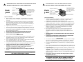
A.
Pack
Joint
The Ford Pack Joint is a
simple convenient method
for connecting to almost any
kind of pipe or tube - iron,
brass, copper, or various
kinds of plastic
Clamp Screw
Wrench flats for Pack
Joint Nut
EPDM Rubber Gasket
with backup gasket
Split Clamp with Grooves
Threads on body of
value or fitting
WARNING: Do not use on gas lines. Installation on gas lines
can result in serious injury or death.
Pasos para instalación
1. Asegurarse que el tubo es redondo, no aplastado. En la tubería de cobre,
usar una herramienta de redondeo, si es necesario. Limpiar o raspar
cualquier polvo o corrosión para que la superficie sea lisa.
2. El tubo debe ser insertado en el accesorio de manera que el fin del tubo pase del
empaque sellador de goma. Si la tuerca o el cubo parece muy grande pare el tubo,
asegurarse de usar un accesorio correcto y que el tubo sea del diámetro correcto.
3. Apretar la tuerca Pack Joint 1 o 1-1/2 giros después de que el empaque
empieza a comprimirse. Si el tornillo de la abrazadera no es accesible,
recolocar apretando la tuerca Pack Joint.
4. Para asegurarse de que el tubo no va a reventar, apretar firmemente la
abrazadera. Es preferible un dado o una llave cerada o abierta a un
destornillador. Evite el sobre apretar que pueda causar deformación de la
tubería.
5. SIEMPRE PROBAR CON PRESIÓN PARA DETECTAR FUGAS ANTES DE
RELLENAR.
6. CONSULTE A SU PROVEEDOR O FABRICANTE DE LA TUBERIA PARA
REQUERIMIENTOS DE INSTALACION ESPECIFICOS.
PRECAUCIONES
1. Los accesorios de bronce se pueden dañar con el manejo incorrecto. Proteger
las roscas. No usar las llaves con ajuste flojo. No dejarlas caer. Rellenar y
apisonar con cuidado para no fatigar los accesorios por el peso de la tierra.
2. Si usted no está familiarizado con conexiones Pack Joint, practique y pruebe
en el taller.
3. Usar un atiezador sólido de metal y del tamaño apropiado con cualquier tubo de
plástico que se puede deformar o fluir en frío bajo presión de la goma Pack Joint
o de la abrazadera.
4. Inspeccionar y probar para fugas las uniones, válvulas y accesorios antes
de rellenar. Si esto es imposible y cuando hay varias comprometidas,
asegúrese de probar el sistema mientras el trabajo está en progreso en vez de
esperar hasta que se complete los servicios. Hacer reparaciones después de
rellenar es costoso.
5. Tenga mucho cuidado con presiones altas de agua (más de 100 psi) y
con tubería de más de 1".
AVISO IMPORTANTE - LEER CON CUIDADO ANTES DE INSTALAR
INSTRUCCIONES PARA CONEXIONES PACK JOINT
A.
El Pack Joint de Ford es un
método simple y conveniente
de conectar con casi toda
clase de tubería o cañeria -
hierro, bronce, cobre o varios
tipos de plástico
Tornillo para la Abrazadera
caras de llave para
Joint Nut
Empaque de Goma EPDM con
empaque de respaldo
Sujetador apartido con ranuras
Roscas en el cuerpo de
la válvula o accessorio
Pack
Joint
PRECAUCION/AVISO: No usar en líneas de gas.
Instalación en líneas de gas puede resultar en
heridas y lesiones serias incluyendo muerte.

1. Prepare service tubing for connection by cleaning, deburring and rounding
if necessary.
2. When using plastic pipe or tubing, install proper size solid, Ford tubular metal
insert stiffener in the pipe / tubing.
3. After selecting the proper size GRIP JOINT fitting, loosen the grip nut and
insert tubing into the nut through the grip ring and gasket. The tubing should
be inserted into the fitting so that the end of tubing is well past the rubber seal
gasket. (The grip nut can also be disassembled from the fitting as long as the
internal parts are kept in the order shown in the diagram above.) Remove burrs
from pipe / tubing for easier insertion.
4. Hold the body of the GRIP JOINT fitting stationary while installing the nut.
Tighten the nut 1-1/2 to 2-1/2 turns past hand tight.
5. Always pressure test for leaks before backfilling. Failure to observe these
instructions will void the manufacturers warranty.
PRECAUTIONS
1. Brass fittings can be damaged by improper handling. Protect threads. Avoid
loose fitting wrenches. Do not drop. Backfill and compact carefully so that
fittings and pipe are not unsupported and stressed by the weight of the earth.
2. If you are unfamiliar with GRIP JOINT connections, a little practice and
testing in the shop before going on the job is time well spent.
3. Use insert stiffeners with any plastic pipe or tubing.
4. Inspect and test all joints, valves and fittings for leaks before backfilling.
5. Use extra care with higher pressures (over 100 PSI) and with pipe over 1".
6. CONSULT PIPE OR TUBING MANUFACTURER FOR SPECIFIC
INSTALLATION REQUIREMENTS.
IMPORTANT NOTICE - READ CAREFULLY BEFORE INSTALLATION
INSTRUCTIONS FOR GRIP JOINT CONNECTIONS
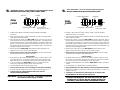
B.
GRIP NUT
GRIPPER WASHER
GASKET
COUPLING OR
PACK JOINT SOCKET
Grip
Joint
WARNING: Do not use on gas lines. Installation on gas lines
can result in serious injury or death.
1. Preparar la tubería de servicio para conexión. Limpie y, quite las rebabas y
redondee la tuburía si es necesario.
2. Cuando usando cualquier tubería de plástico, instale un atiezador sólido de metal
para el tamaño adecuado.
3. Después de escoger el accesorio GRIP JOINT del tamaño adecuado, afloje la
tuerca de apriete e inserte el tubo en la tuerca por el anillo de apriete y el empaque.
El tubo debe ser insertado en el accesorio de manera que el fin del tubo está
más allá del empaque sellador de goma. (La tuerca de aprieto también puede ser
desarmada del accesorio mientras que las partes interiores están mantenidas en el
orden que muestra el diagrama arriba.)
4. Agarre bien el cuerpo del accesorio GRIP JOINT mientras instale la Tuerca.
Apriete la tuerca hasta que no gire al fin de sus roscas interiores.
5. Siempre pruebe con presión para fugas antes de rellenar. Dejar de cumplir
estas instrucciones anulará la garantía del fabricante.
PRECAUCIONES
1. Se pueden dañar los ajustes de cobre con manejo incorrecto. Proteja las roscas.
No use llaves con ajuste flojo. No lo deje caer. Rellenar y apisonar con cuidado
para que los ajustes no sean fatigados por el peso de la tierra.
2. Si usted no está familiarizado con conexiones GRIP JOINT, practique y pruebe en
el taller.
3. Use atiezadores con cualquier tubería o cañería de plástico.
4. Revise y pruebe todos los acoples, válvulas y accesorios por fugas antes de rellenar.
5. Tenga mucho cuidado con presiones muy altas (más de 100 PSI) y con tubos con
diámetros mas de 1".
6. CONSULTE A SU PROVEEDOR O FABRICANTE DE LA TUBERIA PARA
REQUERIMIENTOS DE INSTALACION ESPECIFICOS.
AVISO IMPORTANTE - LEER CON CUIDADO ANTES DE INSTALAR
INSTRUCCIONES DE INSTALACIÓN DE
GRIP JOINT
B.
TUERCA DE APRIETE
SUJETADOR ARANDELA
EMPAQUE
ACOPLE O
CUBO PACK JOINT
Grip
Joint
PRECAUCION/AVISO: No usar en líneas de gas.
Instalación en líneas de gas puede resultar en
heridas y lesiones serias incluyendo muerte.

Steps for Installation
1. Make sure pipe is round, not flattened. On copper tubing use a rounding
tool if necessary. Clean or scrape off any dirt or corrosion so that surface
is smooth.
2. Use proper size Ford solid tubular metal insert stiffeners with any plastic pipe
that is likely to distort or cold flow under pressure of the Quick Joint rubber or
gripper.
3. The tubing should be inserted into the fitting so that the end of the tubing is
well past the rubber seal gasket.
4. Tighten Quick Joint nut until it contacts the machined sleeve stop.
5. ALWAYS PRESSURE TEST FOR LEAKS BEFORE BACKFILLING.
6. CONSULT PIPE OR TUBING MANUFACTURER FOR SPECIFIC
INSTALLATION REQUIREMENTS.
PRECAUTIONS
1. Brass fittings can be damaged by improper handling. Protect threads.
Avoid loose fitting wrenches. Do not drop. Backfill and compact carefully
so that fittings are not stressed by the weight of the earth.
2. It is very important to always ensure tubing is not under-size at the
compression connection location. Undersized tubing can allow
leakage or slippage, causing an unsafe condition.
3. If you are unfamiliar with Quick Joint connections, a little practice and testing
in the shop before going on the job is time well spent.
4. Inspect and test all joints, valves, and fittings for leaks before backfilling.
If this is impossible and when several are involved, be sure to test system as
job progresses instead of waiting until all services are completed. Making
repairs after backfilling is costly.
5. Use extra care with higher water pressures (over 100psi) and with pipe over 1”.
6. NOTE: The Ford Quick Joint IS NOT interchangeable with other
compression fittings.
WARNING: Do not use on gas lines. Installation on gas lines
can result in serious injury or death.
IMPORTANT NOTICE - READ CAREFULLY BEFORE INSTALLATION
INSTRUCTIONS FOR QUICK JOINT CONNECTIONS
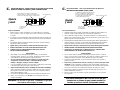
C.
QUICK JOINT NUT
COUPLING OR
QUICK JOINT
SOCKET
MACHINED SLEEVE STOP
METAL GASKET TIP CONTACTS SLEEVE AND
COPPER TUBING FOR ELECTRICAL CONDUCTIVITY.
CONDUCTIVE SPRING MUST FACE COUPLING BODY
Quick
Joint
Pasos para instalación
1. Asegúrese que el tubo es redondo, no aplastado. En tubería de cobre redondee si es
necesario. Limpie o raspe cualquier polvo o corrosión para superficie lisa.
2. Usar un atiezador sólido de metal y del tamaño apropiado con cualquier tubo de
plástico que se puede deformar o fluir en frío bajo presión de la goma Quick Joint o
gripper (anillo de acero que amordaza).
3. El tubo deberá ser insertado dentro del accessorio para que el extremo del tubo pase el
empaque de goma. Si la tuerca o el cubo parece muy grande para el tubo, asegúrese
que se esté usando el accesorio correcto y que el tubo es del diámetro correcto.
4. Apriete la tuerca de Quick Joint hasta que toque el tope del manguito maquinado.
5. SIEMPRE PRUEBE CON PRESIÓN PARA FUGAS ANTES DE RELLENAR.
6. CONSULTE A SU PROVEEDOR O FABRICANTE DE LA TUBERIA PARA
REQUERIMIENTOS DE INSTALACION ESPECIFICOS.
PRECAUCIONES
1. Los accesorios de bronce puedan ser dañado por manejo incorrecto. Proteja las
roscas. No use las llaves con ajuste flojo. No lo deje caer. Rellenar y apisonar con
cuidado para que los accesorios no sean fatigados por el peso de la tierra.
2. Si usted no está familiarizado con las conexiones de Quick Joint, practique y
pruebe en el taller.
3. Inspeccione y pruebe todas los uniones, válvulas, y accesorios para fugas antes
de rellenar. Si esto es imposible y cuando hay varias comprometidas, asegúrese que
se pruebe el sistema mientras que el trabajo avance en vez de esperar hasta que todos
los servicios estén listos. Hacer reparaciones después de rellenar es costoso.
4. Tenga mucho cuidado con presiones de agua más altas (más de 100 psi) y con
tubería de diámetros mayor de 1".
5. NOTA: El Quick Joint de Ford NO se puede intercambiar con otro conexíon
de compresión.
AVISO IMPORTANTE - LEER CON CUIDADO ANTES DE INSTALAR
INSTRUCCIONES PARA QUICK JOINT
C.
EL BORDE DE LA MANGA DEL EMPAQUE DE
METAL Y LA TUBERÍA DE COBRE PARA EL
RESORTE CONDUCTIVO DEBE AFRONTAR
EL CUERPO DEL ACOPLADOR PARA
CONDUCTABILIDAD ELÉCTRICA.
TUERCA DE QUICK JOINT
CUBO DE
QUICK JOINT O
ACOPLAMIENTO
TOPE DE MANGUITO MAQUINADO
Quick
Joint
PRECAUCION/AVISO: No usar en líneas de gas.
Instalación en líneas de gas puede resultar en
heridas y lesiones serias incluyendo muerte.

020035 04/09
THE FORD METER BOX COMPANY, INC.
P.O. Box 443, Wabash, Indiana, USA 46992-0443
Teléfono: 260-563-3171
FAX Doméstico: 800-826-3487 • FAX Internacional: 260-563-0167
http://www.fordmeterbox.com
POR FAVOR EVITAR USAR LLAVES QUE QUEDAN
FLOJOS/SUELTOS Y LLAVES DE TUBOS. USO
INADECUADO DE LLAVES PUEDE CAUSAR DAÑO
AL PRODUCTO
GARANTÍA – LEER ANTES DE INSTALAR
Se garantiza que la mercancia se encuentra libre
de defectos en materiales y manufactura de fábrica.
Proveeremos sin costo alguno nuevos productos en
cantidades iguales por los que resulten defectuosos
dentro de un año después de la fecha de envío de
nuestra fábrica. El fabricante no será responsable por
ninguna pérdida, daño o herida, ya sea directa o por
consecuencia, como resultado del uso o el no poder usar
el producto. Antes de usar, el usuario debe determinar
la conveniencia del producto para su uso intencional
y toma todo riesgo y responsabilidad con respecto al
mismo. No se permiten reclamos por labor o daño por
consecquencia. No se puede cambiar lo anterior escrito
sino por acuerdo firmado por un oficial del fabricante.
DAÑADO CAUSADO POR LOS HERRAMIENTOS
O MANEJO INCORRECTO ANULARÁ NUESTRA
GARANTÍA.
THE FORD METER BOX COMPANY, INC.
P.O. Box 443, Wabash, Indiana, USA 46992-0443
Phone: 260-563-3171 • Domestic FAX: 800-826-3487 • Overseas FAX: 260-563-0167
http://www.fordmeterbox.com
AVOID LOOSE-FITTING WRENCHES AND PIPE
WRENCHES. IMPROPER WRENCH USAGE
CAN DAMAGE PRODUCT
WARRANTY - READ BEFORE INSTALLING
All merchandise is warranted to be free from defects
in material and factory workmanship. We will provide
free of charge new products in equal quantities for
any that prove defective within one year from date
of shipment from our factory. Manufacturer shall not
be liable for any loss, damage, or injury, direct or
consequential, arising out of the use of or the inability
to use the product. Before using, user shall determine
the suitability of product for his intended use and user
assumes all risk and liability whatever in connection
therewith. No claims for labor or consequential
damage will be allowed. The foregoing may not be
changed except by agreement signed by an officer of
the manufacturer.
DAMAGE CAUSED BY IMPROPER TOOLS OR
HANDLING WILL VOID OUR WARRANTY
020035 04/09
-
 1
1
-
 2
2
-
 3
3
-
 4
4
-
 5
5


