Miele APCL Serie Instrucciones de operación
- Tipo
- Instrucciones de operación

Umbau- und Montageanweisung
M.-Nr. 11313351 1 von 25
Diese Unterlagen dürfen ohne unsere Genehmigung weder vervielfältigt noch Dritten zugänglich gemacht werden. Eigentumsrechte vorbehalten. 20.01.2020
de Montageanweisung APCL
Sockel 15/30
en Installation instructions for
APCLplinth 15/30
en-
US
APCL 15/30 stand installation
instructions
es Instrucciones de montaje APCL
zócalo 15/30
fi Asennusohje – Jalusta
APCL15/30
fr Notice de montage socle APCL
15/30
it Istruzioni di montaggio APCL
zoccolo 15/30
nl Montage-instructie APCL
sokkel 15/30
sl Navodila za montažo podnožja
APCL15/30
1

Umbau- und Montageanweisung
2 von 25 M.-Nr. 11313351
20.01.2020 Diese Unterlagen dürfen ohne unsere Genehmigung weder vervielfältigt noch Dritten zugänglich gemacht werden. Eigentumsrechte vorbehalten.
2

Umbau- und Montageanweisung
M.-Nr. 11313351 3 von 25
Diese Unterlagen dürfen ohne unsere Genehmigung weder vervielfältigt noch Dritten zugänglich gemacht werden. Eigentumsrechte vorbehalten. 20.01.2020
3

Umbau- und Montageanweisung
4 von 25 M.-Nr. 11313351
20.01.2020 Diese Unterlagen dürfen ohne unsere Genehmigung weder vervielfältigt noch Dritten zugänglich gemacht werden. Eigentumsrechte vorbehalten.
4

Umbau- und Montageanweisung
M.-Nr. 11313351 5 von 25
Diese Unterlagen dürfen ohne unsere Genehmigung weder vervielfältigt noch Dritten zugänglich gemacht werden. Eigentumsrechte vorbehalten. 20.01.2020
5
6

Umbau- und Montageanweisung
6 von 25 M.-Nr. 11313351
20.01.2020 Diese Unterlagen dürfen ohne unsere Genehmigung weder vervielfältigt noch Dritten zugänglich gemacht werden. Eigentumsrechte vorbehalten.
7
de
Montageanweisung APCL Sockel 15/30
Grund: Mit dem Sockel kann eine ergonomischere Arbeitshöhe für eine Waschmaschine oder einen Trockner erreicht
werden.
Enthaltene Teile
Anzahl M.-Nr. Benennung
1 Sockel
2 Spannlasche
4 Scheibe B6,4
2 Sechskantschraube M6x30
4 Sechskantmutter M6
4 Dübel S12
4 Scheibe 8,4
4 Sechskantholzschraube 8x65
8 Scheibe 15x44x3
8 Unterlage
2 Spannplatte
4 Linsenschraube CEM6x12
2 Sechskantschraube M6x20
1 Vorderwand (nur Sockel geschlossen)
2 Seitenwand (nur Sockel geschlossen)
12 Linsenschraube M4x25 (nur Sockel geschlossen)

Umbau- und Montageanweisung
M.-Nr. 11313351 7 von 25
Diese Unterlagen dürfen ohne unsere Genehmigung weder vervielfältigt noch Dritten zugänglich gemacht werden. Eigentumsrechte vorbehalten. 20.01.2020
Gefahr durch unsachgemäße Instandhaltungsarbeiten
WARNUNG
Gefahr durch unsachgemäße Instandhaltungsarbeiten.
Unsachgemäße Instandhaltungsarbeiten können hohen Sachschaden und schwere
Verletzungen mit Todesfolge verursachen.
A Instandhaltungsarbeiten dürfen nur von einer Elektrofachkraft mit fachlicher
Ausbildung, Fachkenntnissen und Facherfahrungen durchgeführt werden.
A Gültige Sicherheitsbestimmungen müssen berücksichtigt werden.
A Erst die Technische Service Dokumentation (TSD) lesen, dann handeln.
Maßnahmen, bevor Instandhaltungsarbeiten am Gerät durchgeführt werden
– Elektrische Sicherheitsprüfung durchführen.
– Sämtliche Geräteanschlüsse entsprechend der Gebrauchsanweisung von der
Installation trennen.
Maßnahmen, nachdem Instandhaltungsarbeiten am Gerät durchgeführt wurden
– Elektrische Sicherheitsprüfung durchführen.
– Gerät auf Funktion prüfen.
Schnittverletzungsgefahr bei Instandhaltungsarbeiten
WARNUNG
Bauteile können fertigungsbedingt scharfkantig sein.
Schnittverletzungsgefahr bei Instandhaltungsarbeiten.
A Zum Schutz vor Schnittverletzungen Schutzhandschuhe tragen.
Verletzungsgefahr durch übermäßige körperliche Beanspruchung
WARNUNG
Verletzungsgefahr durch übermäßige körperliche Beanspruchung.
Verletzung der Wirbelsäule.
A Das Gewicht der Geräte im Verhältnis zur eigenen körperlichen Kraft beachten.
Gewichtsangabe des Gerätes, siehe Geräte-Gebrauchsanweisung.
Sockel vorbereiten
A Spannplatten auf der Rückseite des Sockels mit je 2 Schrauben 6x12 anschrauben, siehe Abb. 1.
Der eingestanzte Pfeil auf der Oberseite des Sockels weist zur Front, siehe Abb. 1.
A Sockel auf dem Boden ausrichten.
A Bohrlöcher anzeichnen.
A An den Markierungen Löcher mit Durchmesser 12mm etwa 65mm tief bohren.
A Dübel (5) in die Bohrlöcher stecken, siehe Abb. 2.

Umbau- und Montageanweisung
8 von 25 M.-Nr. 11313351
20.01.2020 Diese Unterlagen dürfen ohne unsere Genehmigung weder vervielfältigt noch Dritten zugänglich gemacht werden. Eigentumsrechte vorbehalten.
A Sockel mit den beiliegenden Unterlagen (4) gerade ausrichten, siehe Abb. 2.
A Sockel mit den Sechskantholzschrauben (1), den Scheiben 8,4 (2) und den Scheiben 15x44x3 (3) auf dem Boden
befestigen, siehe Abb. 2.
Waschmaschine auf Sockel montieren
A Spannlaschen auf dem Sockel in den entsprechenden Löchern (1) befestigen, siehe Abb. 3.
A Dazu die Spannlaschen mit je einer Sechskantschraube M6x30 (1), 2 Scheiben verzinkt B6,4 (2) und einer
Sechskantmutter M6 (3) am Sockel befestigen. Die Muttern aber noch nicht festziehen, siehe Abb. 4.
A Füße der Waschmaschine mindestens 5mm herausdrehen.
A Waschmaschine auf den Sockel stellen und mit den hinteren Füßen in die Spannplatten schieben.
A Waschmaschine auf dem Sockel endgültig ausrichten.
A Waschmaschine mit den Spannlaschen an den vorderen Füßen fixieren, siehe Abb. 4.
A Mit je einer weiteren Mutter M6 (4) die 1. Mutter kontern, siehe Abb. 4.
A Je 1 Schraube (1) M6x20 in die Spannplatten einschrauben und festziehen, siehe Abb. 5.
Trockner auf Sockel montieren
A Füße des Trockners mindestens 5mm herausdrehen.
A Trockner auf den Sockel stellen und mit den hinteren Füßen in die Spannplatten schieben.
A Trockner auf dem Sockel endgültig ausrichten.
A Je 1 Schraube (1) M6x20 in die Spannplatten einschrauben und festziehen, siehe Abb. 6.
Sockelwände montieren
A Beide Seitenwände mit jeweils 4 Schrauben M4x25 anschrauben, siehe Abb. 7.
A Vorderwand mit 4 Schrauben M4x25 anschrauben, siehe Abb. 7.
de
en
Installation instructions for APCLplinth 15/30
Reason: Fitting a washing machine or tumble dryer on a plinth enables a more ergonomic height to be achieved.
Included parts
No. Mat. no. Designation
1 Plinth
2 Tensioning strip
4 Washer B6.4
2 Hexagonal bolt M6x30
4 Nut M6
4 Plug S12
4 Washer 8.4
4 Hexagonal-head wood screw 8x65
8 Washer 15x44x3
8 Underlay
2 Clamping plate
4 Raised-head screw CEM6x12
2 Hexagonal bolt M6x20

Umbau- und Montageanweisung
M.-Nr. 11313351 9 von 25
Diese Unterlagen dürfen ohne unsere Genehmigung weder vervielfältigt noch Dritten zugänglich gemacht werden. Eigentumsrechte vorbehalten. 20.01.2020
No. Mat. no. Designation
1 Front panel (box plinth only)
2 Side panel (box plinth only)
12 Raised-head screw M4x25 (box plinth only)
Danger due to incorrectly carried out service and repair work
WARNING
Danger due to incorrectly carried out service and repair work
There is a risk of serious damage, injury and even death if service and repair work is
carried out incorrectly.
A Service and repair work should only be carried out by a suitably qualified electrician
with specialist training, knowledge and experience.
A All appropriate safety regulations must be taken into account.
A First read the Technical Service Documentation (TSD), then commence work.
Measures to be carried out before commencing any service work
– Carry out appropriate electrical safety checks.
– Disconnect all machine utility connections in accordance with the operating
instructions.
Measures to be carried out after service work has been completed
– Carry out appropriate electrical safety checks.
– Check the appliance for correct operation.
Risk of cuts during service and maintenance work
WARNING
Components may have sharp edges.
There is a risk of cuts during service and maintenance work.
A Protective gloves should be worn.
Danger of injury due to excess physical strain
WARNING
Danger of injury due to excess physical strain.
Spinal injuries.
A The relation of the weight of the machines to the physical strength of the technician
must be taken into account. For machine weight details, see the operating
instructions.
Preparing the plinth
A Use 2 screws (6x12) to attach each of the clamping plates to the rear of the plinth, see Fig.1.

Umbau- und Montageanweisung
10 von 25 M.-Nr. 11313351
20.01.2020 Diese Unterlagen dürfen ohne unsere Genehmigung weder vervielfältigt noch Dritten zugänglich gemacht werden. Eigentumsrechte vorbehalten.
The arrow embossed on the top of the plinth points to the front, see Fig.1.
A Level the plinth on the floor.
A Mark the hole positions.
A Drill holes measuring 12mm in diameter in the marked positions, to a depth of approximately 65mm.
A Insert plugs (5) into the holes, see Fig.2.
A Line the plinth up with the underlay supplied (4), see Fig.2.
A Fasten the plinth to the floor with the hexagonal-head wood screws (1), 8.4 washers (2) and 15x44x3 washers (3),
see Fig.2.
Fitting a washing machine to the plinth
A Fit the tensioning strips on the plinth and fasten them in the appropriate holes (1), see Fig.3.
A Secure each tensioning strip to the plinth with 1 M6x30 bolt (1), 2 galvanised B6.4 washers (2) and 1 M6 nut (3). Do
not tighten the nuts yet, see Fig.4.
A Unscrew the washing machine feet by at least 5mm.
A Set the washing machine down on the plinth and slide it into the clamping plates with the rear feet.
A Level the washing machine on the plinth.
A Use the tensioning strips to fix the washing machine to the front feet, see Fig.4.
A Fit another M6 nut (4) to each of the feet to counter the first nut, see Fig.4.
A Screw 1 M6x20 screw (1) into each of the clamping plates and tighten, see Fig.5.
Fitting a tumble dryer to the plinth
A Unscrew the tumble dryer feet by at least 5mm.
A Set the tumble dryer down on the plinth and slide it into the clamping plates with the rear feet.
A Level the tumble dryer on the plinth.
A Screw one M6x20 screw (1) into each of the clamping plates and tighten, see Fig.6.
Fitting the plinth panels
A Use four M4x25 screws to attach each of the two side panels, see Fig.7.
A Use four M4x25 screws to attach the front panel, see Fig.7.
en
en-US
APCL 15/30 stand installation instructions
Reason: Installing a washer or dryer on a stand enables a more ergonomic height to be achieved.
Parts included
Quantity Mat. no. Designation
1 Stand
2 Clamp
4 B6.4 washer
2 M6 x 30 bolt
4 M6 nut
4 S12 plug

Umbau- und Montageanweisung
M.-Nr. 11313351 11 von 25
Diese Unterlagen dürfen ohne unsere Genehmigung weder vervielfältigt noch Dritten zugänglich gemacht werden. Eigentumsrechte vorbehalten. 20.01.2020
Quantity Mat. no. Designation
4 8.4 washer
4 8 x 65 wood screw
8 15 x 44 x 3 washer
8 Spacer
2 Clamping plate
4 CEM 6 x 12 raised-head screw
2 M6 x 20 bolt
1 Front panel (closed stand only)
2 Side panel (closed stand only)
12 M4 x 25 raised-head screw (closed stand only)
Danger due to incorrectly carried out service and repair work
WARNING
Danger due to incorrectly carried out service and repair work.
There is a risk of serious damage, injury and even death if service and repair work is
carried out incorrectly.
A Service and repair work should only be carried out by a suitably qualified electrician
with specialist training, knowledge and experience.
A All appropriate safety regulations must be taken into account.
A Read the technical service documentation (TSD) before starting service work.
Measures to be carried out before starting any service work
– Carry out appropriate electrical safety checks.
– Disconnect all machine utility connections in accordance with the operating
instructions.
Measures to be carried out after service work has been completed
– Carry out appropriate electrical safety checks.
– Check the appliance for correct operation.
Risk of cuts
WARNING
Components are sharp.
Risk of cuts during service work.
A Wear protective gloves.

Umbau- und Montageanweisung
12 von 25 M.-Nr. 11313351
20.01.2020 Diese Unterlagen dürfen ohne unsere Genehmigung weder vervielfältigt noch Dritten zugänglich gemacht werden. Eigentumsrechte vorbehalten.
Risk of injury due to excessive physical strain
WARNING
Risk of injury due to excessive physical strain.
Spinal injuries.
A The relation of the weight of the machine to the physical strength of the technician
must be taken into account. For machine weight details, see the operating
instructions.
Stand preparation
A Use two 6 x 12 screws to attach each of the clamping plates to the rear of the stand; see Fig.1.
The arrow embossed on the top of the stand points to the front; see Fig. 1.
A Level the stand on the floor.
A Mark the hole positions.
A Drill 12mm dia. holes in the marked positions approx. 65mm deep.
A Insert plugs (5) in the holes; see Fig. 2.
A Level the stand using the provided washers (4); see Fig.2.
A Fasten the stand to the floor using the hex-head wood screws (1), 8.4 washers (2) and 15 x 44 x 3 washers (3); see
Fig. 2.
Installing a washer on the stand
A Install the clamps on the stand and fasten them in the appropriate holes (1); see Fig.3.
A Secure each clamp to the stand with one M6 x 30 bolt (1), two galvanized B6.4 washers (2) and an M6 nut (3). Do not
tighten the nuts yet; see Fig.4.
A Unscrew the washing-machine feet by at least 5mm.
A Place the washing machine on the stand and slide its rear feet into the clamping plates.
A Level the washing machine on the stand.
A Use the clamps to secure the washing machine to the front feet; see Fig.4.
A Install a second M6 nut (4) on each of the feet to counter the first nut; see Fig.4.
A Screw one M6 x 20 screw (1) into each of the clamping plates and tighten; see Fig.5.
Installing a dryer on the stand
A Unscrew the dryer feet by at least 5mm.
A Place the dryer on the stand and slide its rear feet into the clamping plates.
A Level the dryer on the stand.
A Screw one M6x20 screw (1) into each of the clamping plates and tighten; see Fig.6.
Installing the stand panels
A Use four M4x25 screws to attach each of the two side panels; see Fig.7.
A Use four M4x25 screws to attach the front panel; see Fig.7.
en-US
es

Umbau- und Montageanweisung
M.-Nr. 11313351 13 von 25
Diese Unterlagen dürfen ohne unsere Genehmigung weder vervielfältigt noch Dritten zugänglich gemacht werden. Eigentumsrechte vorbehalten. 20.01.2020
Instrucciones de montaje APCL zócalo 15/30
Motivo: Con el zócalo se consigue una altura de trabajo más ergonómica para la lavadora o la secadora.
Piezas del suministro
Número Nº de mat. Denominación
1 Zócalo
2 Pestaña tensora
4 Arandela B6,4
2 Tornillo hexagonal M6x30
4 Tuerca hexagonal M6
4 Taco S12
4 Arandela 8,4
4 Tornillo hexagonal para madera 8x65
8 Arandela 15x44x3
8 Placa
2 Placa tensora
4 Tornillo alomado CEM 6x12
2 Tornillo hexagonal M6x20
1 Pared frontal (solo zócalo cerrado)
2 Pared lateral (solo zócalo cerrado)
12 Tornillo alomado M4x25 (solo zócalo cerrado)
Peligro por trabajos de reparación incorrectos
AVISO
Peligro por trabajos de reparación incorrectos.
Los trabajos de reparación incorrectos pueden causar importantes daños materiales,
lesiones graves o incluso la muerte.
A Los trabajos de reparación se realizarán exclusivamente por un técnico especialista
autorizado con formación técnica, conocimientos especializados y experiencia.
A Tener en cuenta las disposiciones de seguridad en vigor.
A Primero leer la Documentación del Servicio Técnico (TSD) y posteriormente actuar.
Medidas antes de realizar trabajos de mantenimiento en el aparato
– Realizar una comprobación de seguridad eléctrica.
– Desconectar todas las conexiones del aparato según se indica en las instrucciones de
manejo antes de la instalación.
Medidas después de realizar trabajos de mantenimiento en el aparato
– Realizar una comprobación de seguridad eléctrica.
– Comprobar el funcionamiento del aparato.

Umbau- und Montageanweisung
14 von 25 M.-Nr. 11313351
20.01.2020 Diese Unterlagen dürfen ohne unsere Genehmigung weder vervielfältigt noch Dritten zugänglich gemacht werden. Eigentumsrechte vorbehalten.
Peligro de sufrir cortes al realizar trabajos de mantenimiento
AVISO
Los componentes pueden presentar cantos afilados debidos a la fabricación.
Peligro de sufrir cortes al realizar trabajos de mantenimiento.
A Como medida de protección contra cortes, llevar guantes de protección.
Peligro de lesiones por esfuerzo físico elevado
AVISO
Peligro de lesiones por esfuerzo físico elevado.
Daños en la columna vertebral.
A Tener en cuenta el peso del aparato en relación a la propia fuerza física. Para
consultar el peso del aparato, véanse las instrucciones de manejo del aparato.
Preparar el zócalo
A Atornillar las placas tensoras a la parte trasera del zócalo con 2tornillos 6x12 cada una, véase imagen1.
La flecha troquelada en la cara superior del zócalo indica hacia el frontal, véase imagen1.
A Nivelar el zócalo sobre el suelo.
A Marcar los orificios del taladro.
A En las marcas, taladrar orificios de 12mm de diámetro y aprox. 65mm de profundidad.
A Introducir los tacos (5) en los orificios del taladro, véase imagen2.
A Nivelar el zócalo con las placas(4) para que quede recto, véase imagen2.
A Fijar al suelo el zócalo con los tornillos de madera hexagonales (1), las arandelas 8,4 (2) y las arandelas
15x44x3(3), véase imagen 2.
Montar la lavadora sobre el zócalo
A Fijar las pestañas tensoras en el zócalo en los orificios correspondientes(1), véase imagen3.
A Para ello, fijar las pestañas tensoras en el zócalo con un tornillo hexagonal M6x30 (1) cada una, dos arandelas
galvanizadas B6,4(2) y una tuerca hexagonal M6(3). No apretar todavía las tuercas, ver imagen4.
A Desenroscar las patas de la lavadora al menos 5mm.
A Colocar la lavadora sobre el zócalo e introducirla en las placas tensoras con las patas traseras.
A Nivelar la lavadora sobre el zócalo de manera definitiva.
A Fijar la lavadora con las pestañas tensoras a las patas delanteras, véase imagen4.
A En cada caso, asegurar la primera tuerca con otra tuerca M6 (4), véase imagen 4.
A Atornillar un tornillo(1) M6x20 en cada placa tensora y apretarlo, véase imagen5.
Montar la secadora en el zócalo
A Desenroscar las patas de la secadora al menos 5mm.
A Colocar la secadora sobre el zócalo e introducir las patas en las placas tensoras.
A Nivelar la secadora sobre el zócalo de manera definitiva.
A Atornillar un tornillo(1) M6x20 en cada placa tensora y apretarlo, véase imagen6.

Umbau- und Montageanweisung
M.-Nr. 11313351 15 von 25
Diese Unterlagen dürfen ohne unsere Genehmigung weder vervielfältigt noch Dritten zugänglich gemacht werden. Eigentumsrechte vorbehalten. 20.01.2020
Montar las paredes del zócalo
A Atornillar las dos paredes laterales con 4 tornillos M4x25 cada una, véase imagen7.
A Atornillar la pared frontal con 4 tornillos M4x25, véase imagen7.
es
fi
Asennusohje – Jalusta APCL15/30
Syy: Jalustan avulla pesukone tai kuivausrumpu saadaan ergonomisemmalle työskentelykorkeudelle.
Mukana toimitettavat osat
Määrä Mat.nro Nimitys
1 Jalusta
2 Kiristyslaatta
4 Aluslaatta B6,4
2 Kuusiokantaruuvi M6x30
4 Kuusiokantamutteri M6
4 Ruuvitulppa S12
4 Aluslaatta 8,4
4 Kuusiokantainen puuruuvi 8x65
8 Aluslaatta 15x44x3
8 Aluslevy
2 Kiinnityslevy
4 Kupukantaruuvi CEM6x12
2 Kuusiokantaruuvi M6x20
1 Etulevy (vain umpinainen jalusta)
2 Sivuseinä (vain umpinainen jalusta)
12 Kupukantaruuvi M4x25 (vain umpinainen jalusta)
Asiattomat korjaukset voivat aiheuttaa huomattavia vaaratilanteita
VAROITUS
Asiattomat korjaukset voivat aiheuttaa huomattavia vaaratilanteita.
Asiattomat korjaukset saattavat aiheuttaa vakavia esine- ja henkilövahinkoja ja jopa
kuoleman.
A Asennustyöt on annettava periaatteessa aina valtuutetun sähköasentajan tehtäväksi,
jolla on asianmukainen ammatillinen koulutus sekä ammatilliset tiedot, taidot ja
työkokemus.
A Asennustöissä on noudatettava voimassa olevia turvallisuusmääräyksiä.
A Lue Tekniset huoltotiedot (TSD) ennen huoltotöiden aloittamista.
Ennen asennustöiden aloittamista suoritettavat toimenpiteet
– Suorita sähköturvallisuuden tarkastus.
– Irrota kaikki liitännät koneen käyttöohjeen mukaisesti ennen asennustöiden
aloittamista.

Umbau- und Montageanweisung
16 von 25 M.-Nr. 11313351
20.01.2020 Diese Unterlagen dürfen ohne unsere Genehmigung weder vervielfältigt noch Dritten zugänglich gemacht werden. Eigentumsrechte vorbehalten.
Huoltotöiden jälkeen suoritettavat toimenpiteet
– Suorita sähköturvallisuuden tarkastus.
– Tarkasta koneen toiminta.
Huoltotöiden yhteydessä on olemassa viiltohaavojen vaara
VAROITUS
Laitteessa voi rakenteellisista syistä olla teräviä reunoja.
Huoltotöiden yhteydessä on olemassa viiltohaavojen vaara
A Käytä viiltohaavojen ehkäisemiseksi suojakäsineitä.
Liian suuren fyysisen rasituksen aiheuttama loukkaantumisvaara
VAROITUS
Liian suuren fyysisen rasituksen aiheuttama loukkaantumisvaara.
Selkärankavammojen vaara.
A Koneet ovat painavia. Älä yritä nostaa niitä yksin, jos voimasi eivät riitä siihen.
Tarkista koneiden nettopaino niiden omista käyttöohjeista.
Jalustan esivalmistelu
A Ruuvaa kumpikin kiinnityslevy jalustan takapuolelle kahdella ruuvilla 6x12, ks. kuva1.
Jalustan yläreunaan stanssattu nuoli osoittaa etureunaa, ks. kuva1.
A Aseta jalusta oikeaan asentoon lattialle.
A Merkitse porattavien reikien paikat.
A Poraa merkitsemiisi kohtiin reiät, joiden halkaisija on 12mm ja syvyys n. 65mm.
A Työnnä ruuvitulpat (5) reikiin, ks. kuva2.
A Suorista jalusta mukana toimitettujen aluslevyjen (4) avulla, ks. kuva2.
A Kiinnitä jalusta lattiaan kuusiokantaisilla puuruuveilla (1), aluslaatoilla 8,4 (2) ja aluslaatoilla 15x44x3 (3), ks. kuva2.
Pesukoneen asennus jalustalle
A Kiinnitä kiristyslaatat jalustaan niille tarkoitettuihin reikiin (1), ks. kuva3.
A Kiinnitä kumpikin kiristyslaatta jalustaan yhdellä kuusiokantaruuvilla M6x30 (1), kahdella sinkityllä aluslaatalla B6,4
(2) ja yhdellä kuusiokantamutterilla M6 (3). Älä kuitenkaan kiristä muttereita vielä, ks. kuva4.
A Kierrä pesukoneen jalkoja ulos vähintään 5mm.
A Aseta pesukone jalustalle ja työnnä sen takajalat kiinnityslevyihin.
A Suorista pesukone huolellisesti jalustalle.
A Kiinnitä pesukoneen etujalat kiristyslaatoilla, ks. kuva4.
A Kiristä kummankin kiristyslaatan ensimmäinen mutteri asettamalla toinen M6 vastamutteriksi (4), ks. kuva4.
A Kierrä kumpaankin kiinnityslevyyn yksi ruuvi (1) M6x20 ja kiristä, ks. kuva5.
Kuivausrummun asennus jalustalle
A Kierrä kuivausrummun jalkoja ulos vähintään 5mm.
A Aseta kuivausrumpu jalustalle ja työnnä sen takajalat kiinnityslevyihin.

Umbau- und Montageanweisung
M.-Nr. 11313351 17 von 25
Diese Unterlagen dürfen ohne unsere Genehmigung weder vervielfältigt noch Dritten zugänglich gemacht werden. Eigentumsrechte vorbehalten. 20.01.2020
A Suorista kuivausrumpu huolellisesti jalustalle.
A Kierrä kumpaankin kiinnityslevyyn 1 ruuvi (1) M6x20 ja kiristä ne, ks. kuva6.
Jalustan seinien asennus
A Kiinnitä kumpikin sivuseinä 4 ruuvilla M4x25, ks. kuva7.
A Kiinnitä etulevy 4 ruuvilla M4x25, ks. kuva7.
fi
fr
Notice de montage socle APCL 15/30
Motif: Le socle permet d'atteindre une hauteur de travail plus ergonomique pour un lave-linge ou un sèche-linge.
Pièces fournies
Nombre N° Mat. Dénomination
1 Socle
2 Patte de fixation
4 Rondelle B6,4
2 Vis à six pans M6x30
4 Écrou à six pans M6
4 Cheville S12
4 Rondelle 8,4
4 Vis à bois à six pans creux 8x65
8 Rondelle 15x44x3
8 Support
2 Plaque de serrage
4 Vis à tête bombée CEM 6x12
2 Vis à six pans M6x20
1 Paroi avant (uniquement socle fermé)
2 Paroi latérale (uniquement socle fermé)
12 Vis à tête bombée M4x25 (uniquement socle fermé)
Danger en cas de travaux de maintenance non conformes
AVERTISSEMENT
Danger en cas de travaux de maintenance non conformes.
Des travaux de maintenance non conformes peuvent causer des dommages matériels
élevés ainsi que de graves blessures avec conséquences mortelles.
A Les travaux de maintenance doivent être exécutés uniquement par un électricien
qualifié possédant la formation, les connaissances et l'expérience professionnelles
adéquates.
A Les consignes de sécurité en vigueur doivent être respectées.
A Lire la documentation technique du Service (TSD) avant d'agir.

Umbau- und Montageanweisung
18 von 25 M.-Nr. 11313351
20.01.2020 Diese Unterlagen dürfen ohne unsere Genehmigung weder vervielfältigt noch Dritten zugänglich gemacht werden. Eigentumsrechte vorbehalten.
Mesures à prendre avant la réalisation de travaux de maintenance sur l’appareil
– Effectuer un contrôle de sécurité électrique.
– Débrancher tous les câbles raccordant l'appareil à l'installation comme indiqué dans le
mode d'emploi.
Mesures à respecter après la réalisation des travaux de maintenance sur l'appareil
– Effectuer un contrôle de sécurité électrique.
– Contrôler le fonctionnement de l'appareil.
Risque de coupure lors des travaux d'entretien
AVERTISSEMENT
Les composants peuvent présenter des arêtes vives liées à la fabrication.
Risque de coupure lors des travaux d'entretien
A Pour se protéger des risques de coupure, porter des gants de protection.
Risque de blessures dus à un effort physique excessif
AVERTISSEMENT
Risque de blessures dus à un effort physique excessif
Blessure au niveau de la colonne vertébrale.
A Prendre en compte le poids des appareils et ne pas surestimer sa force. Voir le mode
d'emploi de l'appareil pour le poids de l'appareil.
Préparation du socle
A Visser les plaques de fixation au dos du socle à l'aide de 2vis 6x12, voir fig. 1.
La flèche en relief sur le dessus du socle montre vers l'avant, voir fig. 1.
A Aligner le socle sur le sol.
A Marquer les trous de perçage.
A Au niveau des marquages, percer des trous d'un diamètre de 12mm à environ 65mm de profondeur.
A Enficher les chevilles (5) dans les trous de perçage, voir fig. 2.
A Mettre le socle à niveau avec les supports joints, voir fig. 2.
A Fixer le socle au sol avec les vis à bois à tête hexagonale (1), les rondelles 8,4 (2) et les rondelles 15x44x3 (3), voir
Fig. 2.
Installer le lave-linge sur le socle
A Fixer les pattes de fixation sur le socle en utilisant les trous correspondants (1), voir fig. 3.
A Pour ce faire, fixer chacune des pattes de fixation au socle à l'aide d'une vis à six pans M6x30 (1), de 2rondelles
galvanisées B6,4 (2) et d'un écrou à six pans M6 (3). Ne pas encore serrer les écrous, voir fig. 4.
A Retirer les pieds du lave-linge d'au moins 5mm.
A Placer le lave-linge sur le socle et pousser à l'aide des pieds arrières dans les plaques de fixation.
A Ajuster le lave-linge définitivement sur le socle.
A Fixer le lave-linge à l'aide des pattes de fixation sur les pieds avant, voir fig. 4.

Umbau- und Montageanweisung
M.-Nr. 11313351 19 von 25
Diese Unterlagen dürfen ohne unsere Genehmigung weder vervielfältigt noch Dritten zugänglich gemacht werden. Eigentumsrechte vorbehalten. 20.01.2020
A Bloquer chaque écrou avec un contre-écrou M6 (4), voir Fig. 4.
A Visser et serrer 1 vis chacune (1) M6x20 dans les plaques de fixation, voir fig. 5.
Monter le sèche-linge sur le socle
A Dévisser les pieds du sèche-linge d'au moins 5mm.
A Placer le sèche-linge sur le socle et pousser à l'aide des pieds arrières dans les plaques de fixation.
A Ajuster le sèche-linge définitivement sur le socle.
A Visser et serrer 1 vis chacune (1) M6x20 dans les plaques de fixation, voir fig. 6.
Monter les parois du socle
A Visser les deux parois latérales avec 4vis respectivement M4x25, voir fig. 7.
A Visser la paroi avant avec 4 vis M4x25, voir fig. 7.
fr
it
Istruzioni di montaggio APCL zoccolo 15/30
Scopo: con lo zoccolo è possibile ottenere un'altezza di lavoro più ergonomica per una lavatrice o un'asciugatrice.
Pezzi contenuti
Numero M.-Nr. Denominazione
1 Zoccolo
2 Griffa di ancoraggio
4 Rondella B 6,4
2 Vite esagonale M6 x 30
4 Dado esagonale M6
4 Tassello S12
4 Rondella 8,4
4 Vite per legno esagonale 8x65
8 Rondella 15 x 44 x 3
8 Base
2 Pannello di trucioli
4 Vite lenticolare CEM6x12
2 Vite esagonale M6x20
1 Parete anteriore (solo zoccolo chiuso)
2 Parete laterale (solo zoccolo chiuso)
12 Vite lenticolare M4x25 (solo zoccolo chiuso)

Umbau- und Montageanweisung
20 von 25 M.-Nr. 11313351
20.01.2020 Diese Unterlagen dürfen ohne unsere Genehmigung weder vervielfältigt noch Dritten zugänglich gemacht werden. Eigentumsrechte vorbehalten.
Pericoli dovuti a lavori di manutenzione non corretti
AVVERTENZA
Pericoli dovuti a lavori di manutenzione non corretti
Lavori di riparazione o manutenzione eseguiti in maniera non corretta possono
provocare danni materiali ingenti e ferite gravi, anche la morte.
A Riparazioni e manutenzioni possono essere effettuate solo da elettricisti qualificati,
che dispongono delle necessarie competenze e di specifica esperienza nel settore.
A Rispettare le disposizioni sulla sicurezza vigenti.
A Leggere dapprima la documentazione tecnica di servizio (TSD), poi agire.
Misure da intraprendere prima di effettuare lavori di riparazione sull'elettrodomestico
– Effettuare una verifica della sicurezza elettrica.
– Staccare tutti gli allacciamenti delle macchine come descritto nelle istruzioni.
Cosa fare dopo aver effettuato i lavori di riparazione sulla macchina
– Effettuare una verifica della sicurezza elettrica.
– Verificare il funzionamento della macchina.
Pericolo di ferimento da taglio in caso di lavori di riparazione/manutenzione
AVVERTENZA
Per motivi di lavorazione, alcuni componenti possono risultare taglienti.
Pericolo di ferimento da taglio in caso di lavori di riparazione/manutenzione.
A Per evitare ferite da taglio, indossare i guanti protettivi.
Pericolo di ferimento a causa di eccessiva sollecitazione fisica
AVVERTENZA
Pericolo di ferimento a causa di eccessiva sollecitazione fisica.
Ferimento della colonna vertebrale.
A Considerare il peso degli apparecchi rispetto alla propria forza fisica. Per le
indicazioni sul peso dell'apparecchio, consultare le istruzioni d'uso dell'apparecchio.
Preparare lo zoccolo
A Avvitare i pannelli di trucioli sulla parete posteriore dello zoccolo con rispettivamente 2 viti 6x12, v. fig. 1.
La freccia punzonata sul lato superiore dello zoccolo è rivolta verso il frontale, v. fig. 1.
A Regolare lo zoccolo sul pavimento.
A Tracciare i fori.
A Sulle tracce praticare i fori con diametro di 12 mm e profondità di circa 65 mm.
A Inserire i tasselli (5) nei fori, v. fig. 2.
A Registrare lo zoccolo con le basi allegate (4), v. fig. 2.

Umbau- und Montageanweisung
M.-Nr. 11313351 21 von 25
Diese Unterlagen dürfen ohne unsere Genehmigung weder vervielfältigt noch Dritten zugänglich gemacht werden. Eigentumsrechte vorbehalten. 20.01.2020
A Fissare lo zoccolo con le viti esagonali per legno (1), le rondelle 8,4 (2) e le rondelle 15 x 44 x 3 (3) alla base, v. fig. 2.
Montare la lavatrice sullo zoccolo
A Fissare le griffe di ancoraggio sullo zoccolo nei rispettivi fori (1), v. fig. 3.
A A tale scopo fissare le griffe di ancoraggio con rispettivamente una vite esagonale M6x30 (1), 2 rondelle zincate B6,4
(2) e un dado esagonale M6 (3) allo zoccolo. Non stringere ancora i dadi, v. fig. 4.
A Svitare i piedini della lavatrice per almeno 5 mm.
A Sistemare la lavatrice sullo zoccolo e spostarla con i piedini posteriori nelle griffe di ancoraggio.
A Registrare definitivamente la lavatrice sullo zoccolo.
A Fissare la lavatrice con le griffe di ancoraggio sui piedini anteriori, v. fig. 4.
A Con rispettivamente un altro dado M6 (4) bloccare il 1° dado, v. fig. 4.
A Avvitare e stringere rispettivamente 1 vite (1) M6x20 nei pannelli di trucioli, v. fig. 5.
Montare l'asciugatrice sullo zoccolo
A Svitare i piedini dell'asciugatrice per almeno 5 mm.
A Sistemare l'asciugatrice sullo zoccolo e spostarla con i piedini posteriori nelle griffe di ancoraggio.
A Registrare definitivamente l'asciugatrice sullo zoccolo.
A Avvitare e stringere rispettivamente 1 vite (1) M6x20 nelle griffe di ancoraggio, v. fig. 6.
Montare le pareti dello zoccolo
A Avvitare entrambe le pareti laterali con rispettivamente 4 viti M4x25, v. fig. 7.
A Avvitare la parete anteriore con 4 viti M4x25, v. fig. 7.
it
nl
Montage-instructie APCL sokkel 15/30
Reden: met de sokkel kunt u de werkhoogte voor een wasmachine of een droger verbeteren.
Onderdelen
Aantal Mat.-nr. Aanduiding
1 Sokkel
2 Spanstrip
4 Ring B6,4
2 Zeskantschroef M6 x 30
4 Zeskantmoer M6
4 Plug S12
4 Ring 8,4
4 Zeskanthoutschroef 8 x 65
8 Ring 15 x 44 x 3
8 Plaatje
2 Spanplaat
4 Lenskopschroef CEM 6 x 12
2 Zeskantschroef M6 x 20
1 Voorkant (alleen bij gesloten sokkel)
2 Zijkant (alleen bij gesloten sokkel)

Umbau- und Montageanweisung
22 von 25 M.-Nr. 11313351
20.01.2020 Diese Unterlagen dürfen ohne unsere Genehmigung weder vervielfältigt noch Dritten zugänglich gemacht werden. Eigentumsrechte vorbehalten.
Aantal Mat.-nr. Aanduiding
12 Lenskopschroef M4x25 (alleen bij gesloten sokkel)
Risico door ondeskundig onderhoud
WAARSCHUWING
Risico door ondeskundig onderhoud.
Ondeskundig onderhoud kan veel schade en ernstig letsel veroorzaken en
levensgevaarlijk zijn.
A Werkzaamheden mogen alleen door een vakman uitgevoerd worden
A met inachtneming van alle geldende veiligheidsvoorschriften.
A Lees eerst de Technische Service Documentatie (TSD) voordat u uw werkzaamheden
begint.
Wat u moet doen voordat er werkzaamheden aan het apparaat worden uitgevoerd
– Controleer de elektrische veiligheid.
– Maak alle aansluitingen los overeenkomstig de gebruiksaanwijzing.
Wat u moet doen na voltooiing van de werkzaamheden
– Controleer de elektrische veiligheid.
– Controleer of het apparaat werkt.
U kunt zich snijden bij onderhouds-/reparatiewerkzaamheden
WAARSCHUWING
De randen van de onderdelen kunnen scherp zijn.
U kunt zich snijden bij onderhouds-/reparatiewerkzaamheden
A Draag veiligheidshandschoenen om snijwonden te voorkomen.
Kans op letsel door te hoge lichamelijke inspanning
WAARSCHUWING
Kans op letsel door te hoge lichamelijke inspanning
Kans op letsel aan de wervelkolom.
A Let op het gewicht van de apparaten in verhouding tot de eigen fysieke kracht. Het
gewicht van het apparaat wordt in de bijbehorende gebruiksaanwijzing vermeld.
Sokkel voorbereiden
A Schroef de spanplaten aan de achterkant van de sokkel met 2 schroeven van 6 x 12 vast, zie afb. 1.
De pijl die op de bovenkant van de sokkel gestanst is, wijst naar de voorkant, zie afb. 1.
A Plaats de sokkel waterpas op de vloer.
A Markeer de boorgaten.
A Boor bij de markeringen gaten met een diameter van 12 mm en een diepte van ca. 65 mm.

Umbau- und Montageanweisung
M.-Nr. 11313351 23 von 25
Diese Unterlagen dürfen ohne unsere Genehmigung weder vervielfältigt noch Dritten zugänglich gemacht werden. Eigentumsrechte vorbehalten. 20.01.2020
A Steek de pluggen (5) in de boorgaten, zie afb. 2.
A Zet de sokkel met de meegeleverde plaatjes (4) recht, zie afb. 2.
A Zet de sokkel met de zeskanthoutschroeven (1), de ringen 8,4 (2) en de ringen 15x44x3 (3) op de vloer vast, zie
afb. 2.
Wasmachine op de sokkel monteren
A Bevestig de spanstrips op de sokkel in de daarvoor bestemde gaten (1), zie afb. 3.
A Zet de spanstrips met telkens een zeskantschroef M6 x 30 (1), 2 verzinkte ringen B6,4 (2) en een zeskantmoer M6 (3)
op de sokkel vast. Draai de moeren echter nog niet vast, zie afb. 4.
A Draai de voeten van de wasmachine minstens 5 mm naar buiten.
A Plaats de wasmachine op de sokkel en schuif de machine met de achterste voeten in de spanplaten.
A Stel de wasmachine op de sokkel definitief af.
A Zet de wasmachine met de spanstrips bij de voorste voeten vast, zie afb. 4.
A Gebruik een extra moer M6 (4) als contramoer voor de 1e moer, zie afb. 4.
A Schroef telkens 1 schroef (1) M6 x 20 in de spanplaten en draai de schroef vast, zie afb. 5.
Droger op de sokkel monteren
A Draai de voeten van de droger minstens 5 mm naar buiten.
A Plaats de droger op de sokkel en schuif de droger met de achterste voeten in de spanplaten.
A Stel de droger op de sokkel definitief af.
A Schroef telkens 1 schroef (1) M6 x 20 in de spanplaten en draai de schroef vast, zie afb. 6.
De zijkanten van de sokkel monteren
A Schroef beide zijkanten elk met 4 schroeven M4 x 25 aan de sokkel vast, zie afb. 7.
A Schroef de voorkant met 4 schroeven M4 x 25 aan de sokkel vast, zie afb. 7.
nl
sl
Navodila za montažo podnožja APCL15/30
Osnova: s podnožjem lahko dosežemo bolj ergonomsko delovno višino za pralni ali sušilni stroj.
Vključeni deli
Število Št. mat. Ime
1 Podnožje
2 Vpenjalna spona
4 Podložka B6,4
2 Šestrobi vijak M6x30
4 Šestroba matica M6
4 Vložek S12
4 Podložka 8,4
4 Šestrobi lesni vijak 8x65
8 Podložka 15x44x3
8 Podložna ploščica
2 Napenjalna ploščica
4 Vijak z lečasto glavo CEM6x12

Umbau- und Montageanweisung
24 von 25 M.-Nr. 11313351
20.01.2020 Diese Unterlagen dürfen ohne unsere Genehmigung weder vervielfältigt noch Dritten zugänglich gemacht werden. Eigentumsrechte vorbehalten.
Število Št. mat. Ime
2 Šestrobi vijak M6x20
1 Sprednja stena (samo zaprto podnožje)
2 Stranska stena (samo zaprto podnožje)
12 Vijak z lečasto glavo M4x25 (samo zaprto podnožje)
Nevarnost zaradi nestrokovnih vzdrževalnih posegov
OPOZORILO
Nevarnost zaradi nestrokovnih vzdrževalnih posegov.
Nestrokovno izvedena vzdrževalna dela lahko povzročijo veliko materialno škodo in
hude poškodbe s smrtnim izidom.
A Vzdrževalna dela lahko opravljajo samo električarji z ustrezno strokovno izobrazbo,
strokovnim znanjem in izkušnjami na tem področju.
A Upoštevati je treba veljavne varnostne predpise.
A Najprej preberite tehnično servisno dokumentacijo (TSD) in šele nato začnite z delom.
Ukrepi pred izvedbo del na stroju
– Izvedite preizkus električne varnosti.
– Vse priključke stroja ločite od napeljave skladno z navodili za uporabo.
Ukrepi po izvedbi del na stroju
– Izvedite preizkus električne varnosti.
– Preverite delovanje stroja.
Nevarnost ureznin pri vzdrževalnih posegih
OPOZORILO
Sestavni deli so lahko zaradi postopka izdelave ostri.
Nevarnost ureznin pri vzdrževalnih posegih.
A Za zaščito pred urezninami nosite zaščitne rokavice.
Nevarnost poškodbe zaradi čezmerne telesne obremenitve
OPOZORILO
Nevarnost poškodbe zaradi čezmerne telesne obremenitve.
Poškodba hrbtenice.
A Upoštevajte težo stroja glede na svojo telesno moč. Za podatke o teži stroja glejte
navodila za uporabo stroja.
Priprava podnožja
A Na hrbtno stran podnožja privijte napenjalni ploščici s po dvema vijakoma 6x12, glejte sliko 1.
Vdelana puščica na zgornji strani podnožja kaže proti sprednji strani, glejte sliko 1.

Umbau- und Montageanweisung
M.-Nr. 11313351 25 von 25
Diese Unterlagen dürfen ohne unsere Genehmigung weder vervielfältigt noch Dritten zugänglich gemacht werden. Eigentumsrechte vorbehalten. 20.01.2020
A Podnožje poravnajte s tlemi.
A Označite izvrtine.
A Na oznakah izvrtajte luknje premera 12mm in globine približno 65mm.
A V izvrtine vstavite vložke (5), glejte sliko 2.
A Podnožje poravnajte v pokončen položaj s priloženimi podložkami (4), glejte sliko 2.
A Podnožje pritrdite na tla s šestrobimi lesnimi vijaki (1), podložkami 8,4 (2) in podložkami 15x44x3 (3), glejte sliko 2.
Montaža pralnega stroja na podnožje
A Vpenjalne spone pritrdite na podnožje v ustrezne luknje (1), glejte sliko 3.
A V ta namen vpenjalne spone pritrdite na podnožje s po enim šestrobim vijakom M6x30 (1), dvema pocinkanima
podložkama B6,4 (2) in eno šestrobo matico M6 (3). Vendar matic še ne privijte do konca, glejte sliko 4.
A Noge pralnega stroja odvijte vsaj 5mm.
A Pralni stroj postavite na podnožje in ga z zadnjimi nogami potisnite v napenjalni ploščici.
A Pralni stroj na podnožju dokončno poravnajte.
A Pralni stroj fiksirajte z vpenjalnimi sponami na sprednjih nogah, glejte sliko 4.
A S po eno dodatno matico M6 (4) zablokirajte prvo matico, glejte sliko 4.
A V napenjalni ploščici privijte po en vijak (1) M6x20 in ga zategnite, glejte sliko 5.
Montaža sušilnega stroja na podnožje
A Noge sušilnega stroja odvijte vsaj 5mm.
A Sušilni stroj postavite na podnožje in ga z zadnjimi nogami potisnite v napenjalni ploščici.
A Sušilni stroj na podnožju dokončno poravnajte.
A V napenjalni ploščici privijte po en vijak (1) M6x20 in ga zategnite, glejte sliko 6.
Montaža sten podnožja
A Stranski steni privijte na podnožje s po štirimi vijaki M4x25, glejte sliko 7.
A Sprednjo stranico privijte s štirimi vijaki M4x25, glejte sliko 7.
sl
Transcripción de documentos
Umbau- und Montageanweisung M.-Nr. 11313351 de Montageanweisung APCL Sockel 15/30 es it 1 von 25 en Installation instructions for APCL plinth 15/30 enUS APCL 15/30 stand installation instructions Instrucciones de montaje APCL fi zócalo 15/30 Asennusohje – Jalusta APCL 15/30 fr Notice de montage socle APCL 15/30 Istruzioni di montaggio APCL zoccolo 15/30 Montage-instructie APCL sokkel 15/30 sl Navodila za montažo podnožja APCL 15/30 nl 1 Diese Unterlagen dürfen ohne unsere Genehmigung weder vervielfältigt noch Dritten zugänglich gemacht werden. Eigentumsrechte vorbehalten. 20.01.2020 Umbau- und Montageanweisung 2 von 25 M.-Nr. 11313351 2 20.01.2020 Diese Unterlagen dürfen ohne unsere Genehmigung weder vervielfältigt noch Dritten zugänglich gemacht werden. Eigentumsrechte vorbehalten. Umbau- und Montageanweisung M.-Nr. 11313351 3 von 25 3 Diese Unterlagen dürfen ohne unsere Genehmigung weder vervielfältigt noch Dritten zugänglich gemacht werden. Eigentumsrechte vorbehalten. 20.01.2020 Umbau- und Montageanweisung 4 von 25 M.-Nr. 11313351 4 20.01.2020 Diese Unterlagen dürfen ohne unsere Genehmigung weder vervielfältigt noch Dritten zugänglich gemacht werden. Eigentumsrechte vorbehalten. Umbau- und Montageanweisung M.-Nr. 11313351 5 von 25 5 6 Diese Unterlagen dürfen ohne unsere Genehmigung weder vervielfältigt noch Dritten zugänglich gemacht werden. Eigentumsrechte vorbehalten. 20.01.2020 Umbau- und Montageanweisung 6 von 25 M.-Nr. 11313351 7 de Montageanweisung APCL Sockel 15/30 Grund: Mit dem Sockel kann eine ergonomischere Arbeitshöhe für eine Waschmaschine oder einen Trockner erreicht werden. Enthaltene Teile Anzahl 1 2 4 2 4 4 4 4 8 8 2 4 2 1 2 12 20.01.2020 M.-Nr. Benennung Sockel Spannlasche Scheibe B6,4 Sechskantschraube M6 x 30 Sechskantmutter M6 Dübel S12 Scheibe 8,4 Sechskantholzschraube 8 x 65 Scheibe 15 x 44 x 3 Unterlage Spannplatte Linsenschraube CEM6 x 12 Sechskantschraube M6 x 20 Vorderwand (nur Sockel geschlossen) Seitenwand (nur Sockel geschlossen) Linsenschraube M4 x 25 (nur Sockel geschlossen) Diese Unterlagen dürfen ohne unsere Genehmigung weder vervielfältigt noch Dritten zugänglich gemacht werden. Eigentumsrechte vorbehalten. Umbau- und Montageanweisung M.-Nr. 11313351 7 von 25 Gefahr durch unsachgemäße Instandhaltungsarbeiten WARNUNG Gefahr durch unsachgemäße Instandhaltungsarbeiten. Unsachgemäße Instandhaltungsarbeiten können hohen Sachschaden und schwere Verletzungen mit Todesfolge verursachen. A Instandhaltungsarbeiten dürfen nur von einer Elektrofachkraft mit fachlicher Ausbildung, Fachkenntnissen und Facherfahrungen durchgeführt werden. A Gültige Sicherheitsbestimmungen müssen berücksichtigt werden. A Erst die Technische Service Dokumentation (TSD) lesen, dann handeln. Maßnahmen, bevor Instandhaltungsarbeiten am Gerät durchgeführt werden – Elektrische Sicherheitsprüfung durchführen. – Sämtliche Geräteanschlüsse entsprechend der Gebrauchsanweisung von der Installation trennen. Maßnahmen, nachdem Instandhaltungsarbeiten am Gerät durchgeführt wurden – Elektrische Sicherheitsprüfung durchführen. – Gerät auf Funktion prüfen. Schnittverletzungsgefahr bei Instandhaltungsarbeiten WARNUNG Bauteile können fertigungsbedingt scharfkantig sein. Schnittverletzungsgefahr bei Instandhaltungsarbeiten. A Zum Schutz vor Schnittverletzungen Schutzhandschuhe tragen. Verletzungsgefahr durch übermäßige körperliche Beanspruchung WARNUNG Verletzungsgefahr durch übermäßige körperliche Beanspruchung. Verletzung der Wirbelsäule. A Das Gewicht der Geräte im Verhältnis zur eigenen körperlichen Kraft beachten. Gewichtsangabe des Gerätes, siehe Geräte-Gebrauchsanweisung. Sockel vorbereiten A Spannplatten auf der Rückseite des Sockels mit je 2 Schrauben 6 x 12 anschrauben, siehe Abb. 1. Der eingestanzte Pfeil auf der Oberseite des Sockels weist zur Front, siehe Abb. 1. A Sockel auf dem Boden ausrichten. A Bohrlöcher anzeichnen. A An den Markierungen Löcher mit Durchmesser 12 mm etwa 65 mm tief bohren. A Dübel (5) in die Bohrlöcher stecken, siehe Abb. 2. Diese Unterlagen dürfen ohne unsere Genehmigung weder vervielfältigt noch Dritten zugänglich gemacht werden. Eigentumsrechte vorbehalten. 20.01.2020 Umbau- und Montageanweisung 8 von 25 M.-Nr. 11313351 A Sockel mit den beiliegenden Unterlagen (4) gerade ausrichten, siehe Abb. 2. A Sockel mit den Sechskantholzschrauben (1), den Scheiben 8,4 (2) und den Scheiben 15 x 44 x 3 (3) auf dem Boden befestigen, siehe Abb. 2. Waschmaschine auf Sockel montieren A Spannlaschen auf dem Sockel in den entsprechenden Löchern (1) befestigen, siehe Abb. 3. A Dazu die Spannlaschen mit je einer Sechskantschraube M6 x 30 (1), 2 Scheiben verzinkt B6,4 (2) und einer Sechskantmutter M6 (3) am Sockel befestigen. Die Muttern aber noch nicht festziehen, siehe Abb. 4. A Füße der Waschmaschine mindestens 5 mm herausdrehen. A Waschmaschine auf den Sockel stellen und mit den hinteren Füßen in die Spannplatten schieben. A Waschmaschine auf dem Sockel endgültig ausrichten. A Waschmaschine mit den Spannlaschen an den vorderen Füßen fixieren, siehe Abb. 4. A Mit je einer weiteren Mutter M6 (4) die 1. Mutter kontern, siehe Abb. 4. A Je 1 Schraube (1) M6 x 20 in die Spannplatten einschrauben und festziehen, siehe Abb. 5. Trockner auf Sockel montieren A Füße des Trockners mindestens 5 mm herausdrehen. A Trockner auf den Sockel stellen und mit den hinteren Füßen in die Spannplatten schieben. A Trockner auf dem Sockel endgültig ausrichten. A Je 1 Schraube (1) M6 x 20 in die Spannplatten einschrauben und festziehen, siehe Abb. 6. Sockelwände montieren A Beide Seitenwände mit jeweils 4 Schrauben M4 x 25 anschrauben, siehe Abb. 7. A Vorderwand mit 4 Schrauben M4 x 25 anschrauben, siehe Abb. 7. de en Installation instructions for APCL plinth 15/30 Reason: Fitting a washing machine or tumble dryer on a plinth enables a more ergonomic height to be achieved. Included parts No. 1 2 4 2 4 4 4 4 8 8 2 4 2 20.01.2020 Mat. no. Designation Plinth Tensioning strip Washer B6.4 Hexagonal bolt M6 x 30 Nut M6 Plug S12 Washer 8.4 Hexagonal-head wood screw 8 x 65 Washer 15 x 44 x 3 Underlay Clamping plate Raised-head screw CEM 6 x 12 Hexagonal bolt M6 x 20 Diese Unterlagen dürfen ohne unsere Genehmigung weder vervielfältigt noch Dritten zugänglich gemacht werden. Eigentumsrechte vorbehalten. Umbau- und Montageanweisung M.-Nr. 11313351 No. Mat. no. 1 2 12 9 von 25 Designation Front panel (box plinth only) Side panel (box plinth only) Raised-head screw M4 x 25 (box plinth only) Danger due to incorrectly carried out service and repair work WARNING Danger due to incorrectly carried out service and repair work There is a risk of serious damage, injury and even death if service and repair work is carried out incorrectly. A Service and repair work should only be carried out by a suitably qualified electrician with specialist training, knowledge and experience. A All appropriate safety regulations must be taken into account. A First read the Technical Service Documentation (TSD), then commence work. Measures to be carried out before commencing any service work – Carry out appropriate electrical safety checks. – Disconnect all machine utility connections in accordance with the operating instructions. Measures to be carried out after service work has been completed – Carry out appropriate electrical safety checks. – Check the appliance for correct operation. Risk of cuts during service and maintenance work WARNING Components may have sharp edges. There is a risk of cuts during service and maintenance work. A Protective gloves should be worn. Danger of injury due to excess physical strain WARNING Danger of injury due to excess physical strain. Spinal injuries. A The relation of the weight of the machines to the physical strength of the technician must be taken into account. For machine weight details, see the operating instructions. Preparing the plinth A Use 2 screws (6 x 12) to attach each of the clamping plates to the rear of the plinth, see Fig. 1. Diese Unterlagen dürfen ohne unsere Genehmigung weder vervielfältigt noch Dritten zugänglich gemacht werden. Eigentumsrechte vorbehalten. 20.01.2020 Umbau- und Montageanweisung 10 von 25 M.-Nr. 11313351 The arrow embossed on the top of the plinth points to the front, see Fig. 1. A Level the plinth on the floor. A Mark the hole positions. A Drill holes measuring 12 mm in diameter in the marked positions, to a depth of approximately 65 mm. A Insert plugs (5) into the holes, see Fig. 2. A Line the plinth up with the underlay supplied (4), see Fig. 2. A Fasten the plinth to the floor with the hexagonal-head wood screws (1), 8.4 washers (2) and 15 x 44 x 3 washers (3), see Fig. 2. Fitting a washing machine to the plinth A Fit the tensioning strips on the plinth and fasten them in the appropriate holes (1), see Fig. 3. A Secure each tensioning strip to the plinth with 1 M6 x 30 bolt (1), 2 galvanised B6.4 washers (2) and 1 M6 nut (3). Do not tighten the nuts yet, see Fig. 4. A Unscrew the washing machine feet by at least 5 mm. A Set the washing machine down on the plinth and slide it into the clamping plates with the rear feet. A Level the washing machine on the plinth. A Use the tensioning strips to fix the washing machine to the front feet, see Fig. 4. A Fit another M6 nut (4) to each of the feet to counter the first nut, see Fig. 4. A Screw 1 M6 x 20 screw (1) into each of the clamping plates and tighten, see Fig. 5. Fitting a tumble dryer to the plinth A Unscrew the tumble dryer feet by at least 5 mm. A Set the tumble dryer down on the plinth and slide it into the clamping plates with the rear feet. A Level the tumble dryer on the plinth. A Screw one M6 x 20 screw (1) into each of the clamping plates and tighten, see Fig. 6. Fitting the plinth panels A Use four M4 x 25 screws to attach each of the two side panels, see Fig. 7. A Use four M4 x 25 screws to attach the front panel, see Fig. 7. en en-US APCL 15/30 stand installation instructions Reason: Installing a washer or dryer on a stand enables a more ergonomic height to be achieved. Parts included Quantity Mat. no. Designation 1 2 4 2 4 4 Stand Clamp B6.4 washer M6 x 30 bolt M6 nut S12 plug 20.01.2020 Diese Unterlagen dürfen ohne unsere Genehmigung weder vervielfältigt noch Dritten zugänglich gemacht werden. Eigentumsrechte vorbehalten. Umbau- und Montageanweisung M.-Nr. 11313351 11 von 25 Quantity Mat. no. Designation 4 4 8 8 2 4 2 1 2 12 8.4 washer 8 x 65 wood screw 15 x 44 x 3 washer Spacer Clamping plate CEM 6 x 12 raised-head screw M6 x 20 bolt Front panel (closed stand only) Side panel (closed stand only) M4 x 25 raised-head screw (closed stand only) Danger due to incorrectly carried out service and repair work WARNING Danger due to incorrectly carried out service and repair work. There is a risk of serious damage, injury and even death if service and repair work is carried out incorrectly. A Service and repair work should only be carried out by a suitably qualified electrician with specialist training, knowledge and experience. A All appropriate safety regulations must be taken into account. A Read the technical service documentation (TSD) before starting service work. Measures to be carried out before starting any service work – Carry out appropriate electrical safety checks. – Disconnect all machine utility connections in accordance with the operating instructions. Measures to be carried out after service work has been completed – Carry out appropriate electrical safety checks. – Check the appliance for correct operation. Risk of cuts WARNING Components are sharp. Risk of cuts during service work. A Wear protective gloves. Diese Unterlagen dürfen ohne unsere Genehmigung weder vervielfältigt noch Dritten zugänglich gemacht werden. Eigentumsrechte vorbehalten. 20.01.2020 Umbau- und Montageanweisung 12 von 25 M.-Nr. 11313351 Risk of injury due to excessive physical strain WARNING Risk of injury due to excessive physical strain. Spinal injuries. A The relation of the weight of the machine to the physical strength of the technician must be taken into account. For machine weight details, see the operating instructions. Stand preparation A Use two 6 x 12 screws to attach each of the clamping plates to the rear of the stand; see Fig. 1. The arrow embossed on the top of the stand points to the front; see Fig. 1. A Level the stand on the floor. A Mark the hole positions. A Drill 12mm dia. holes in the marked positions approx. 65mm deep. A Insert plugs (5) in the holes; see Fig. 2. A Level the stand using the provided washers (4); see Fig. 2. A Fasten the stand to the floor using the hex-head wood screws (1), 8.4 washers (2) and 15 x 44 x 3 washers (3); see Fig. 2. Installing a washer on the stand A Install the clamps on the stand and fasten them in the appropriate holes (1); see Fig. 3. A Secure each clamp to the stand with one M6 x 30 bolt (1), two galvanized B6.4 washers (2) and an M6 nut (3). Do not tighten the nuts yet; see Fig. 4. A Unscrew the washing-machine feet by at least 5mm. A Place the washing machine on the stand and slide its rear feet into the clamping plates. A Level the washing machine on the stand. A Use the clamps to secure the washing machine to the front feet; see Fig. 4. A Install a second M6 nut (4) on each of the feet to counter the first nut; see Fig. 4. A Screw one M6 x 20 screw (1) into each of the clamping plates and tighten; see Fig. 5. Installing a dryer on the stand A Unscrew the dryer feet by at least 5mm. A Place the dryer on the stand and slide its rear feet into the clamping plates. A Level the dryer on the stand. A Screw one M6x20 screw (1) into each of the clamping plates and tighten; see Fig. 6. Installing the stand panels A Use four M4x25 screws to attach each of the two side panels; see Fig. 7. A Use four M4x25 screws to attach the front panel; see Fig. 7. en-US es 20.01.2020 Diese Unterlagen dürfen ohne unsere Genehmigung weder vervielfältigt noch Dritten zugänglich gemacht werden. Eigentumsrechte vorbehalten. Umbau- und Montageanweisung M.-Nr. 11313351 13 von 25 Instrucciones de montaje APCL zócalo 15/30 Motivo: Con el zócalo se consigue una altura de trabajo más ergonómica para la lavadora o la secadora. Piezas del suministro Número Nº de mat. Denominación 1 2 4 2 4 4 4 4 8 8 2 4 2 1 2 12 Zócalo Pestaña tensora Arandela B6,4 Tornillo hexagonal M6 x 30 Tuerca hexagonal M6 Taco S12 Arandela 8,4 Tornillo hexagonal para madera 8 x 65 Arandela 15 x 44 x 3 Placa Placa tensora Tornillo alomado CEM 6 x 12 Tornillo hexagonal M6 x 20 Pared frontal (solo zócalo cerrado) Pared lateral (solo zócalo cerrado) Tornillo alomado M4 x 25 (solo zócalo cerrado) Peligro por trabajos de reparación incorrectos AVISO Peligro por trabajos de reparación incorrectos. Los trabajos de reparación incorrectos pueden causar importantes daños materiales, lesiones graves o incluso la muerte. A Los trabajos de reparación se realizarán exclusivamente por un técnico especialista autorizado con formación técnica, conocimientos especializados y experiencia. A Tener en cuenta las disposiciones de seguridad en vigor. A Primero leer la Documentación del Servicio Técnico (TSD) y posteriormente actuar. Medidas antes de realizar trabajos de mantenimiento en el aparato – Realizar una comprobación de seguridad eléctrica. – Desconectar todas las conexiones del aparato según se indica en las instrucciones de manejo antes de la instalación. Medidas después de realizar trabajos de mantenimiento en el aparato – Realizar una comprobación de seguridad eléctrica. – Comprobar el funcionamiento del aparato. Diese Unterlagen dürfen ohne unsere Genehmigung weder vervielfältigt noch Dritten zugänglich gemacht werden. Eigentumsrechte vorbehalten. 20.01.2020 Umbau- und Montageanweisung 14 von 25 M.-Nr. 11313351 Peligro de sufrir cortes al realizar trabajos de mantenimiento AVISO Los componentes pueden presentar cantos afilados debidos a la fabricación. Peligro de sufrir cortes al realizar trabajos de mantenimiento. A Como medida de protección contra cortes, llevar guantes de protección. Peligro de lesiones por esfuerzo físico elevado AVISO Peligro de lesiones por esfuerzo físico elevado. Daños en la columna vertebral. A Tener en cuenta el peso del aparato en relación a la propia fuerza física. Para consultar el peso del aparato, véanse las instrucciones de manejo del aparato. Preparar el zócalo A Atornillar las placas tensoras a la parte trasera del zócalo con 2 tornillos 6 x 12 cada una, véase imagen 1. La flecha troquelada en la cara superior del zócalo indica hacia el frontal, véase imagen 1. A Nivelar el zócalo sobre el suelo. A Marcar los orificios del taladro. A En las marcas, taladrar orificios de 12 mm de diámetro y aprox. 65 mm de profundidad. A Introducir los tacos (5) en los orificios del taladro, véase imagen 2. A Nivelar el zócalo con las placas (4) para que quede recto, véase imagen 2. A Fijar al suelo el zócalo con los tornillos de madera hexagonales (1), las arandelas 8,4 (2) y las arandelas 15 x 44 x 3 (3), véase imagen 2. Montar la lavadora sobre el zócalo A Fijar las pestañas tensoras en el zócalo en los orificios correspondientes (1), véase imagen 3. A Para ello, fijar las pestañas tensoras en el zócalo con un tornillo hexagonal M6 x 30 (1) cada una, dos arandelas galvanizadas B6,4 (2) y una tuerca hexagonal M6 (3). No apretar todavía las tuercas, ver imagen 4. A Desenroscar las patas de la lavadora al menos 5 mm. A Colocar la lavadora sobre el zócalo e introducirla en las placas tensoras con las patas traseras. A Nivelar la lavadora sobre el zócalo de manera definitiva. A Fijar la lavadora con las pestañas tensoras a las patas delanteras, véase imagen 4. A En cada caso, asegurar la primera tuerca con otra tuerca M6 (4), véase imagen 4. A Atornillar un tornillo (1) M6 x 20 en cada placa tensora y apretarlo, véase imagen 5. Montar la secadora en el zócalo A Desenroscar las patas de la secadora al menos 5 mm. A Colocar la secadora sobre el zócalo e introducir las patas en las placas tensoras. A Nivelar la secadora sobre el zócalo de manera definitiva. A Atornillar un tornillo (1) M6 x 20 en cada placa tensora y apretarlo, véase imagen 6. 20.01.2020 Diese Unterlagen dürfen ohne unsere Genehmigung weder vervielfältigt noch Dritten zugänglich gemacht werden. Eigentumsrechte vorbehalten. Umbau- und Montageanweisung M.-Nr. 11313351 15 von 25 Montar las paredes del zócalo A Atornillar las dos paredes laterales con 4 tornillos M4 x 25 cada una, véase imagen 7. A Atornillar la pared frontal con 4 tornillos M4 x 25, véase imagen 7. es fi Asennusohje – Jalusta APCL 15/30 Syy: Jalustan avulla pesukone tai kuivausrumpu saadaan ergonomisemmalle työskentelykorkeudelle. Mukana toimitettavat osat Määrä Mat.nro 1 2 4 2 4 4 4 4 8 8 2 4 2 1 2 12 Nimitys Jalusta Kiristyslaatta Aluslaatta B6,4 Kuusiokantaruuvi M6 x 30 Kuusiokantamutteri M6 Ruuvitulppa S12 Aluslaatta 8,4 Kuusiokantainen puuruuvi 8 x 65 Aluslaatta 15 x 44 x 3 Aluslevy Kiinnityslevy Kupukantaruuvi CEM 6 x 12 Kuusiokantaruuvi M6 x 20 Etulevy (vain umpinainen jalusta) Sivuseinä (vain umpinainen jalusta) Kupukantaruuvi M4 x 25 (vain umpinainen jalusta) Asiattomat korjaukset voivat aiheuttaa huomattavia vaaratilanteita VAROITUS Asiattomat korjaukset voivat aiheuttaa huomattavia vaaratilanteita. Asiattomat korjaukset saattavat aiheuttaa vakavia esine- ja henkilövahinkoja ja jopa kuoleman. A Asennustyöt on annettava periaatteessa aina valtuutetun sähköasentajan tehtäväksi, jolla on asianmukainen ammatillinen koulutus sekä ammatilliset tiedot, taidot ja työkokemus. A Asennustöissä on noudatettava voimassa olevia turvallisuusmääräyksiä. A Lue Tekniset huoltotiedot (TSD) ennen huoltotöiden aloittamista. Ennen asennustöiden aloittamista suoritettavat toimenpiteet – Suorita sähköturvallisuuden tarkastus. – Irrota kaikki liitännät koneen käyttöohjeen mukaisesti ennen asennustöiden aloittamista. Diese Unterlagen dürfen ohne unsere Genehmigung weder vervielfältigt noch Dritten zugänglich gemacht werden. Eigentumsrechte vorbehalten. 20.01.2020 Umbau- und Montageanweisung 16 von 25 M.-Nr. 11313351 Huoltotöiden jälkeen suoritettavat toimenpiteet – Suorita sähköturvallisuuden tarkastus. – Tarkasta koneen toiminta. Huoltotöiden yhteydessä on olemassa viiltohaavojen vaara VAROITUS Laitteessa voi rakenteellisista syistä olla teräviä reunoja. Huoltotöiden yhteydessä on olemassa viiltohaavojen vaara A Käytä viiltohaavojen ehkäisemiseksi suojakäsineitä. Liian suuren fyysisen rasituksen aiheuttama loukkaantumisvaara VAROITUS Liian suuren fyysisen rasituksen aiheuttama loukkaantumisvaara. Selkärankavammojen vaara. A Koneet ovat painavia. Älä yritä nostaa niitä yksin, jos voimasi eivät riitä siihen. Tarkista koneiden nettopaino niiden omista käyttöohjeista. Jalustan esivalmistelu A Ruuvaa kumpikin kiinnityslevy jalustan takapuolelle kahdella ruuvilla 6 x 12, ks. kuva 1. Jalustan yläreunaan stanssattu nuoli osoittaa etureunaa, ks. kuva 1. A Aseta jalusta oikeaan asentoon lattialle. A Merkitse porattavien reikien paikat. A Poraa merkitsemiisi kohtiin reiät, joiden halkaisija on 12 mm ja syvyys n. 65 mm. A Työnnä ruuvitulpat (5) reikiin, ks. kuva 2. A Suorista jalusta mukana toimitettujen aluslevyjen (4) avulla, ks. kuva 2. A Kiinnitä jalusta lattiaan kuusiokantaisilla puuruuveilla (1), aluslaatoilla 8,4 (2) ja aluslaatoilla 15 x 44 x 3 (3), ks. kuva 2. Pesukoneen asennus jalustalle A Kiinnitä kiristyslaatat jalustaan niille tarkoitettuihin reikiin (1), ks. kuva 3. A Kiinnitä kumpikin kiristyslaatta jalustaan yhdellä kuusiokantaruuvilla M6 x 30 (1), kahdella sinkityllä aluslaatalla B6,4 (2) ja yhdellä kuusiokantamutterilla M6 (3). Älä kuitenkaan kiristä muttereita vielä, ks. kuva 4. A Kierrä pesukoneen jalkoja ulos vähintään 5 mm. A Aseta pesukone jalustalle ja työnnä sen takajalat kiinnityslevyihin. A Suorista pesukone huolellisesti jalustalle. A Kiinnitä pesukoneen etujalat kiristyslaatoilla, ks. kuva 4. A Kiristä kummankin kiristyslaatan ensimmäinen mutteri asettamalla toinen M6 vastamutteriksi (4), ks. kuva 4. A Kierrä kumpaankin kiinnityslevyyn yksi ruuvi (1) M6 x 20 ja kiristä, ks. kuva 5. Kuivausrummun asennus jalustalle A Kierrä kuivausrummun jalkoja ulos vähintään 5 mm. A Aseta kuivausrumpu jalustalle ja työnnä sen takajalat kiinnityslevyihin. 20.01.2020 Diese Unterlagen dürfen ohne unsere Genehmigung weder vervielfältigt noch Dritten zugänglich gemacht werden. Eigentumsrechte vorbehalten. Umbau- und Montageanweisung M.-Nr. 11313351 17 von 25 A Suorista kuivausrumpu huolellisesti jalustalle. A Kierrä kumpaankin kiinnityslevyyn 1 ruuvi (1) M6 x 20 ja kiristä ne, ks. kuva 6. Jalustan seinien asennus A Kiinnitä kumpikin sivuseinä 4 ruuvilla M4 x 25, ks. kuva 7. A Kiinnitä etulevy 4 ruuvilla M4 x 25, ks. kuva 7. fi fr Notice de montage socle APCL 15/30 Motif : Le socle permet d'atteindre une hauteur de travail plus ergonomique pour un lave-linge ou un sèche-linge. Pièces fournies Nombre N° Mat. Dénomination 1 2 4 2 4 4 4 4 8 8 2 4 2 1 2 12 Socle Patte de fixation Rondelle B6,4 Vis à six pans M6 x 30 Écrou à six pans M6 Cheville S12 Rondelle 8,4 Vis à bois à six pans creux 8 x 65 Rondelle 15 x 44 x 3 Support Plaque de serrage Vis à tête bombée CEM 6 x 12 Vis à six pans M6 x 20 Paroi avant (uniquement socle fermé) Paroi latérale (uniquement socle fermé) Vis à tête bombée M4 x 25 (uniquement socle fermé) Danger en cas de travaux de maintenance non conformes AVERTISSEMENT Danger en cas de travaux de maintenance non conformes. Des travaux de maintenance non conformes peuvent causer des dommages matériels élevés ainsi que de graves blessures avec conséquences mortelles. A Les travaux de maintenance doivent être exécutés uniquement par un électricien qualifié possédant la formation, les connaissances et l'expérience professionnelles adéquates. A Les consignes de sécurité en vigueur doivent être respectées. A Lire la documentation technique du Service (TSD) avant d'agir. Diese Unterlagen dürfen ohne unsere Genehmigung weder vervielfältigt noch Dritten zugänglich gemacht werden. Eigentumsrechte vorbehalten. 20.01.2020 Umbau- und Montageanweisung 18 von 25 M.-Nr. 11313351 Mesures à prendre avant la réalisation de travaux de maintenance sur l’appareil – Effectuer un contrôle de sécurité électrique. – Débrancher tous les câbles raccordant l'appareil à l'installation comme indiqué dans le mode d'emploi. Mesures à respecter après la réalisation des travaux de maintenance sur l'appareil – Effectuer un contrôle de sécurité électrique. – Contrôler le fonctionnement de l'appareil. Risque de coupure lors des travaux d'entretien AVERTISSEMENT Les composants peuvent présenter des arêtes vives liées à la fabrication. Risque de coupure lors des travaux d'entretien A Pour se protéger des risques de coupure, porter des gants de protection. Risque de blessures dus à un effort physique excessif AVERTISSEMENT Risque de blessures dus à un effort physique excessif Blessure au niveau de la colonne vertébrale. A Prendre en compte le poids des appareils et ne pas surestimer sa force. Voir le mode d'emploi de l'appareil pour le poids de l'appareil. Préparation du socle A Visser les plaques de fixation au dos du socle à l'aide de 2 vis 6 x 12, voir fig. 1. La flèche en relief sur le dessus du socle montre vers l'avant, voir fig. 1. A Aligner le socle sur le sol. A Marquer les trous de perçage. A Au niveau des marquages, percer des trous d'un diamètre de 12 mm à environ 65 mm de profondeur. A Enficher les chevilles (5) dans les trous de perçage, voir fig. 2. A Mettre le socle à niveau avec les supports joints, voir fig. 2. A Fixer le socle au sol avec les vis à bois à tête hexagonale (1), les rondelles 8,4 (2) et les rondelles 15 x 44 x 3 (3), voir Fig. 2. Installer le lave-linge sur le socle A Fixer les pattes de fixation sur le socle en utilisant les trous correspondants (1), voir fig. 3. A Pour ce faire, fixer chacune des pattes de fixation au socle à l'aide d'une vis à six pans M6 x 30 (1), de 2 rondelles galvanisées B6,4 (2) et d'un écrou à six pans M6 (3). Ne pas encore serrer les écrous, voir fig. 4. A Retirer les pieds du lave-linge d'au moins 5 mm. A Placer le lave-linge sur le socle et pousser à l'aide des pieds arrières dans les plaques de fixation. A Ajuster le lave-linge définitivement sur le socle. A Fixer le lave-linge à l'aide des pattes de fixation sur les pieds avant, voir fig. 4. 20.01.2020 Diese Unterlagen dürfen ohne unsere Genehmigung weder vervielfältigt noch Dritten zugänglich gemacht werden. Eigentumsrechte vorbehalten. Umbau- und Montageanweisung M.-Nr. 11313351 19 von 25 A Bloquer chaque écrou avec un contre-écrou M6 (4), voir Fig. 4. A Visser et serrer 1 vis chacune (1) M6 x 20 dans les plaques de fixation, voir fig. 5. Monter le sèche-linge sur le socle A Dévisser les pieds du sèche-linge d'au moins 5 mm. A Placer le sèche-linge sur le socle et pousser à l'aide des pieds arrières dans les plaques de fixation. A Ajuster le sèche-linge définitivement sur le socle. A Visser et serrer 1 vis chacune (1) M6 x 20 dans les plaques de fixation, voir fig. 6. Monter les parois du socle A Visser les deux parois latérales avec 4 vis respectivement M4 x 25, voir fig. 7. A Visser la paroi avant avec 4 vis M4 x 25, voir fig. 7. fr it Istruzioni di montaggio APCL zoccolo 15/30 Scopo: con lo zoccolo è possibile ottenere un'altezza di lavoro più ergonomica per una lavatrice o un'asciugatrice. Pezzi contenuti Numero M.-Nr. Denominazione 1 2 4 2 4 4 4 4 8 8 2 4 2 1 2 12 Zoccolo Griffa di ancoraggio Rondella B 6,4 Vite esagonale M6 x 30 Dado esagonale M6 Tassello S12 Rondella 8,4 Vite per legno esagonale 8 x 65 Rondella 15 x 44 x 3 Base Pannello di trucioli Vite lenticolare CEM6 x 12 Vite esagonale M6 x 20 Parete anteriore (solo zoccolo chiuso) Parete laterale (solo zoccolo chiuso) Vite lenticolare M4 x 25 (solo zoccolo chiuso) Diese Unterlagen dürfen ohne unsere Genehmigung weder vervielfältigt noch Dritten zugänglich gemacht werden. Eigentumsrechte vorbehalten. 20.01.2020 Umbau- und Montageanweisung 20 von 25 M.-Nr. 11313351 Pericoli dovuti a lavori di manutenzione non corretti AVVERTENZA Pericoli dovuti a lavori di manutenzione non corretti Lavori di riparazione o manutenzione eseguiti in maniera non corretta possono provocare danni materiali ingenti e ferite gravi, anche la morte. A Riparazioni e manutenzioni possono essere effettuate solo da elettricisti qualificati, che dispongono delle necessarie competenze e di specifica esperienza nel settore. A Rispettare le disposizioni sulla sicurezza vigenti. A Leggere dapprima la documentazione tecnica di servizio (TSD), poi agire. Misure da intraprendere prima di effettuare lavori di riparazione sull'elettrodomestico – Effettuare una verifica della sicurezza elettrica. – Staccare tutti gli allacciamenti delle macchine come descritto nelle istruzioni. Cosa fare dopo aver effettuato i lavori di riparazione sulla macchina – Effettuare una verifica della sicurezza elettrica. – Verificare il funzionamento della macchina. Pericolo di ferimento da taglio in caso di lavori di riparazione/manutenzione AVVERTENZA Per motivi di lavorazione, alcuni componenti possono risultare taglienti. Pericolo di ferimento da taglio in caso di lavori di riparazione/manutenzione. A Per evitare ferite da taglio, indossare i guanti protettivi. Pericolo di ferimento a causa di eccessiva sollecitazione fisica AVVERTENZA Pericolo di ferimento a causa di eccessiva sollecitazione fisica. Ferimento della colonna vertebrale. A Considerare il peso degli apparecchi rispetto alla propria forza fisica. Per le indicazioni sul peso dell'apparecchio, consultare le istruzioni d'uso dell'apparecchio. Preparare lo zoccolo A Avvitare i pannelli di trucioli sulla parete posteriore dello zoccolo con rispettivamente 2 viti 6 x 12, v. fig. 1. La freccia punzonata sul lato superiore dello zoccolo è rivolta verso il frontale, v. fig. 1. A Regolare lo zoccolo sul pavimento. A Tracciare i fori. A Sulle tracce praticare i fori con diametro di 12 mm e profondità di circa 65 mm. A Inserire i tasselli (5) nei fori, v. fig. 2. A Registrare lo zoccolo con le basi allegate (4), v. fig. 2. 20.01.2020 Diese Unterlagen dürfen ohne unsere Genehmigung weder vervielfältigt noch Dritten zugänglich gemacht werden. Eigentumsrechte vorbehalten. Umbau- und Montageanweisung M.-Nr. 11313351 21 von 25 A Fissare lo zoccolo con le viti esagonali per legno (1), le rondelle 8,4 (2) e le rondelle 15 x 44 x 3 (3) alla base, v. fig. 2. Montare la lavatrice sullo zoccolo A Fissare le griffe di ancoraggio sullo zoccolo nei rispettivi fori (1), v. fig. 3. A A tale scopo fissare le griffe di ancoraggio con rispettivamente una vite esagonale M6x30 (1), 2 rondelle zincate B6,4 (2) e un dado esagonale M6 (3) allo zoccolo. Non stringere ancora i dadi, v. fig. 4. A Svitare i piedini della lavatrice per almeno 5 mm. A Sistemare la lavatrice sullo zoccolo e spostarla con i piedini posteriori nelle griffe di ancoraggio. A Registrare definitivamente la lavatrice sullo zoccolo. A Fissare la lavatrice con le griffe di ancoraggio sui piedini anteriori, v. fig. 4. A Con rispettivamente un altro dado M6 (4) bloccare il 1° dado, v. fig. 4. A Avvitare e stringere rispettivamente 1 vite (1) M6 x 20 nei pannelli di trucioli, v. fig. 5. Montare l'asciugatrice sullo zoccolo A Svitare i piedini dell'asciugatrice per almeno 5 mm. A Sistemare l'asciugatrice sullo zoccolo e spostarla con i piedini posteriori nelle griffe di ancoraggio. A Registrare definitivamente l'asciugatrice sullo zoccolo. A Avvitare e stringere rispettivamente 1 vite (1) M6 x 20 nelle griffe di ancoraggio, v. fig. 6. Montare le pareti dello zoccolo A Avvitare entrambe le pareti laterali con rispettivamente 4 viti M4 x 25, v. fig. 7. A Avvitare la parete anteriore con 4 viti M4 x 25, v. fig. 7. it nl Montage-instructie APCL sokkel 15/30 Reden: met de sokkel kunt u de werkhoogte voor een wasmachine of een droger verbeteren. Onderdelen Aantal 1 2 4 2 4 4 4 4 8 8 2 4 2 1 2 Mat.-nr. Aanduiding Sokkel Spanstrip Ring B6,4 Zeskantschroef M6 x 30 Zeskantmoer M6 Plug S12 Ring 8,4 Zeskanthoutschroef 8 x 65 Ring 15 x 44 x 3 Plaatje Spanplaat Lenskopschroef CEM 6 x 12 Zeskantschroef M6 x 20 Voorkant (alleen bij gesloten sokkel) Zijkant (alleen bij gesloten sokkel) Diese Unterlagen dürfen ohne unsere Genehmigung weder vervielfältigt noch Dritten zugänglich gemacht werden. Eigentumsrechte vorbehalten. 20.01.2020 Umbau- und Montageanweisung 22 von 25 Aantal Mat.-nr. 12 M.-Nr. 11313351 Aanduiding Lenskopschroef M4 x 25 (alleen bij gesloten sokkel) Risico door ondeskundig onderhoud WAARSCHUWING Risico door ondeskundig onderhoud. Ondeskundig onderhoud kan veel schade en ernstig letsel veroorzaken en levensgevaarlijk zijn. A Werkzaamheden mogen alleen door een vakman uitgevoerd worden A met inachtneming van alle geldende veiligheidsvoorschriften. A Lees eerst de Technische Service Documentatie (TSD) voordat u uw werkzaamheden begint. Wat u moet doen voordat er werkzaamheden aan het apparaat worden uitgevoerd – Controleer de elektrische veiligheid. – Maak alle aansluitingen los overeenkomstig de gebruiksaanwijzing. Wat u moet doen na voltooiing van de werkzaamheden – Controleer de elektrische veiligheid. – Controleer of het apparaat werkt. U kunt zich snijden bij onderhouds-/reparatiewerkzaamheden WAARSCHUWING De randen van de onderdelen kunnen scherp zijn. U kunt zich snijden bij onderhouds-/reparatiewerkzaamheden A Draag veiligheidshandschoenen om snijwonden te voorkomen. Kans op letsel door te hoge lichamelijke inspanning WAARSCHUWING Kans op letsel door te hoge lichamelijke inspanning Kans op letsel aan de wervelkolom. A Let op het gewicht van de apparaten in verhouding tot de eigen fysieke kracht. Het gewicht van het apparaat wordt in de bijbehorende gebruiksaanwijzing vermeld. Sokkel voorbereiden A Schroef de spanplaten aan de achterkant van de sokkel met 2 schroeven van 6 x 12 vast, zie afb. 1. De pijl die op de bovenkant van de sokkel gestanst is, wijst naar de voorkant, zie afb. 1. A Plaats de sokkel waterpas op de vloer. A Markeer de boorgaten. A Boor bij de markeringen gaten met een diameter van 12 mm en een diepte van ca. 65 mm. 20.01.2020 Diese Unterlagen dürfen ohne unsere Genehmigung weder vervielfältigt noch Dritten zugänglich gemacht werden. Eigentumsrechte vorbehalten. Umbau- und Montageanweisung M.-Nr. 11313351 23 von 25 A Steek de pluggen (5) in de boorgaten, zie afb. 2. A Zet de sokkel met de meegeleverde plaatjes (4) recht, zie afb. 2. A Zet de sokkel met de zeskanthoutschroeven (1), de ringen 8,4 (2) en de ringen 15 x 44 x 3 (3) op de vloer vast, zie afb. 2. Wasmachine op de sokkel monteren A Bevestig de spanstrips op de sokkel in de daarvoor bestemde gaten (1), zie afb. 3. A Zet de spanstrips met telkens een zeskantschroef M6 x 30 (1), 2 verzinkte ringen B6,4 (2) en een zeskantmoer M6 (3) op de sokkel vast. Draai de moeren echter nog niet vast, zie afb. 4. A Draai de voeten van de wasmachine minstens 5 mm naar buiten. A Plaats de wasmachine op de sokkel en schuif de machine met de achterste voeten in de spanplaten. A Stel de wasmachine op de sokkel definitief af. A Zet de wasmachine met de spanstrips bij de voorste voeten vast, zie afb. 4. A Gebruik een extra moer M6 (4) als contramoer voor de 1e moer, zie afb. 4. A Schroef telkens 1 schroef (1) M6 x 20 in de spanplaten en draai de schroef vast, zie afb. 5. Droger op de sokkel monteren A Draai de voeten van de droger minstens 5 mm naar buiten. A Plaats de droger op de sokkel en schuif de droger met de achterste voeten in de spanplaten. A Stel de droger op de sokkel definitief af. A Schroef telkens 1 schroef (1) M6 x 20 in de spanplaten en draai de schroef vast, zie afb. 6. De zijkanten van de sokkel monteren A Schroef beide zijkanten elk met 4 schroeven M4 x 25 aan de sokkel vast, zie afb. 7. A Schroef de voorkant met 4 schroeven M4 x 25 aan de sokkel vast, zie afb. 7. nl sl Navodila za montažo podnožja APCL 15/30 Osnova: s podnožjem lahko dosežemo bolj ergonomsko delovno višino za pralni ali sušilni stroj. Vključeni deli Število 1 2 4 2 4 4 4 4 8 8 2 4 Št. mat. Ime Podnožje Vpenjalna spona Podložka B6,4 Šestrobi vijak M6 x 30 Šestroba matica M6 Vložek S12 Podložka 8,4 Šestrobi lesni vijak 8 x 65 Podložka 15 x 44 x 3 Podložna ploščica Napenjalna ploščica Vijak z lečasto glavo CEM 6 x 12 Diese Unterlagen dürfen ohne unsere Genehmigung weder vervielfältigt noch Dritten zugänglich gemacht werden. Eigentumsrechte vorbehalten. 20.01.2020 Umbau- und Montageanweisung 24 von 25 Število Št. mat. 2 1 2 12 M.-Nr. 11313351 Ime Šestrobi vijak M6 x 20 Sprednja stena (samo zaprto podnožje) Stranska stena (samo zaprto podnožje) Vijak z lečasto glavo M4 x 25 (samo zaprto podnožje) Nevarnost zaradi nestrokovnih vzdrževalnih posegov OPOZORILO Nevarnost zaradi nestrokovnih vzdrževalnih posegov. Nestrokovno izvedena vzdrževalna dela lahko povzročijo veliko materialno škodo in hude poškodbe s smrtnim izidom. A Vzdrževalna dela lahko opravljajo samo električarji z ustrezno strokovno izobrazbo, strokovnim znanjem in izkušnjami na tem področju. A Upoštevati je treba veljavne varnostne predpise. A Najprej preberite tehnično servisno dokumentacijo (TSD) in šele nato začnite z delom. Ukrepi pred izvedbo del na stroju – Izvedite preizkus električne varnosti. – Vse priključke stroja ločite od napeljave skladno z navodili za uporabo. Ukrepi po izvedbi del na stroju – Izvedite preizkus električne varnosti. – Preverite delovanje stroja. Nevarnost ureznin pri vzdrževalnih posegih OPOZORILO Sestavni deli so lahko zaradi postopka izdelave ostri. Nevarnost ureznin pri vzdrževalnih posegih. A Za zaščito pred urezninami nosite zaščitne rokavice. Nevarnost poškodbe zaradi čezmerne telesne obremenitve OPOZORILO Nevarnost poškodbe zaradi čezmerne telesne obremenitve. Poškodba hrbtenice. A Upoštevajte težo stroja glede na svojo telesno moč. Za podatke o teži stroja glejte navodila za uporabo stroja. Priprava podnožja A Na hrbtno stran podnožja privijte napenjalni ploščici s po dvema vijakoma 6 x 12, glejte sliko 1. Vdelana puščica na zgornji strani podnožja kaže proti sprednji strani, glejte sliko 1. 20.01.2020 Diese Unterlagen dürfen ohne unsere Genehmigung weder vervielfältigt noch Dritten zugänglich gemacht werden. Eigentumsrechte vorbehalten. Umbau- und Montageanweisung M.-Nr. 11313351 25 von 25 A Podnožje poravnajte s tlemi. A Označite izvrtine. A Na oznakah izvrtajte luknje premera 12 mm in globine približno 65 mm. A V izvrtine vstavite vložke (5), glejte sliko 2. A Podnožje poravnajte v pokončen položaj s priloženimi podložkami (4), glejte sliko 2. A Podnožje pritrdite na tla s šestrobimi lesnimi vijaki (1), podložkami 8,4 (2) in podložkami 15 x 44 x 3 (3), glejte sliko 2. Montaža pralnega stroja na podnožje A Vpenjalne spone pritrdite na podnožje v ustrezne luknje (1), glejte sliko 3. A V ta namen vpenjalne spone pritrdite na podnožje s po enim šestrobim vijakom M6 x 30 (1), dvema pocinkanima podložkama B6,4 (2) in eno šestrobo matico M6 (3). Vendar matic še ne privijte do konca, glejte sliko 4. A Noge pralnega stroja odvijte vsaj 5 mm. A Pralni stroj postavite na podnožje in ga z zadnjimi nogami potisnite v napenjalni ploščici. A Pralni stroj na podnožju dokončno poravnajte. A Pralni stroj fiksirajte z vpenjalnimi sponami na sprednjih nogah, glejte sliko 4. A S po eno dodatno matico M6 (4) zablokirajte prvo matico, glejte sliko 4. A V napenjalni ploščici privijte po en vijak (1) M6 x 20 in ga zategnite, glejte sliko 5. Montaža sušilnega stroja na podnožje A Noge sušilnega stroja odvijte vsaj 5 mm. A Sušilni stroj postavite na podnožje in ga z zadnjimi nogami potisnite v napenjalni ploščici. A Sušilni stroj na podnožju dokončno poravnajte. A V napenjalni ploščici privijte po en vijak (1) M6 x 20 in ga zategnite, glejte sliko 6. Montaža sten podnožja A Stranski steni privijte na podnožje s po štirimi vijaki M4 x 25, glejte sliko 7. A Sprednjo stranico privijte s štirimi vijaki M4 x 25, glejte sliko 7. sl Diese Unterlagen dürfen ohne unsere Genehmigung weder vervielfältigt noch Dritten zugänglich gemacht werden. Eigentumsrechte vorbehalten. 20.01.2020-
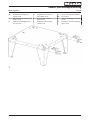 1
1
-
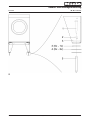 2
2
-
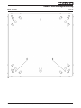 3
3
-
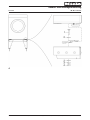 4
4
-
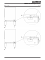 5
5
-
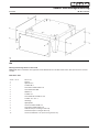 6
6
-
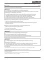 7
7
-
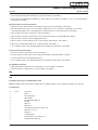 8
8
-
 9
9
-
 10
10
-
 11
11
-
 12
12
-
 13
13
-
 14
14
-
 15
15
-
 16
16
-
 17
17
-
 18
18
-
 19
19
-
 20
20
-
 21
21
-
 22
22
-
 23
23
-
 24
24
-
 25
25


Miele APCL Serie Instrucciones de operación
- Tipo
- Instrucciones de operación
en otros idiomas
- français: Miele APCL Serie Mode d'emploi
- italiano: Miele APCL Serie Istruzioni per l'uso
- English: Miele APCL Serie Operating instructions
- Deutsch: Miele APCL Serie Bedienungsanleitung
- Nederlands: Miele APCL Serie Handleiding
- suomi: Miele APCL Serie Käyttö ohjeet
Artículos relacionados
-
Miele 59501001D Instrucciones de operación
-
Miele 59600801D Instrucciones de operación
-
Miele APCL007BLUE Manual de usuario
-
Miele APCL007BLUE Manual de usuario
-
Miele APCL 054 Manual de usuario
-
-
-
-
-