Sony XR-C800 Manual de usuario
- Categoría
- Receptores de medios de coche
- Tipo
- Manual de usuario
Este manual también es adecuado para

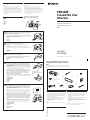
Installation/Connections
Instalación/Conexiones
###
FM/AM
Cassette Car
Stereo
Sony Corporation 1996 Printed in Japan
Parts for installation and connections
Componentes de montaje y conexiones
###
The numbers in the list are keyed to those in the instructions.
Los números de la lista corresponden a los de las instrucciones.
###
23
× 1 × 1× 1
TOP
1
45
6
× 5
(incl. 1 reserve)
(se incluyen 1 de reserva)
###
7
× 1
× 2
× 1 × 1
!º8
× 2
9
× 1
Inverter
•Install the inverter far away from the unit using
double-sided adhesive tape or something similar.
•Do not bundle the inverter's cord with a pincord
or other connecting cord.
•Be sure not to mount the inverter under a mat or
in a place exposed to splashing water of air
conditioner. It may cause electric shock or
damage to the unit.
Note
If the inverter's cord is pinched, the display indications may not
appear.
Inversor
•Instale el inversor alejado de la unidad utilizando
cinta adhesiva por ambas caras o algo similar.
•No bobine el cable del inversor con ning otro
cable conector.
•Cerciese de no montar el inversor debajo de una
alfombrilla ni en un lugar expuesto a
salpicaduras de agua de un acondicionador de
aire. Esto podr provocar descargas eltricas o dar
la unidad.
Nota
Si el cable del inversor quedase pillado, es posible que no
apareciesen las indicaciones del visualizador.
XR-C800
XR-C800W
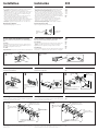
Installing the rotary remote
Notes
• Choose the mounting location carefully so that the rotary
remote will not interfere with operating the car.
• Do not install the rotary remote in a place where it may
jeopardize the safety of the (front) passenger in anyway.
• When installing the rotary remote, be sure not to damage the
electrical cables etc. on the other side of the mounting surface.
• Avoid installing the rotary remote where it may be subject to
high temperatures, such as from direct sunlight or hot air
from the heater etc.
Instalación del mando rotavivo
Notas
• Elija cuidadosamente el lugar de montaje de forma que el
mando rotativo no dificulte la conducción del coche.
• No instale el mando rotativo en un lugar donde pueda poner
en peligro la seguridad del pasajero acompañante.
• Al instalar el mando rotativo, asegúrese de no dañar los cables
de electricidad, etc., del otro lado de la superficie de montaje.
• Procure no instalar el mando rotativo en un lugar expuesto a
altas temperaturas, como a la luz solar directa o al aire
caliente de la calefacción, etc.
#####
#
• ###
• ########
• #########
###
• ########
####
Example of a mounting location
Ejemplo de un lugar de montaje
##
Choose the exact location for the rotary remote to be mounted,
then clean the mounting surface.
Dirt or oil impair the adhesive strength of the double-sided adhesive tape.
Una vez elegido el lugar de montaje del mando rotativo, limpie
previamente la superficie de montaje.
La suciedad o la grasa dañan la intensidad adhesiva de la tira adhesiva por las
dos caras.
#######
###########
Mark two positions for the supplied screws.
Use the screw holes on the mounting hardware 9 to mark the
positions.
Marque dos posiciones para los tornillos suministrados.
Para ello, utilice los orificios para tornillos de la ferretería de montaje
9.
#######
###########
Marks
Marcas
##
9
2
Remove the steering wheel column cover, and drill 2 mm
diameter holes where you have marked.
Extraiga la cubierta de la columna de la dirección y haga orificios
de 2 mm. de diámetro en los lugares marcados.
########
###
Warm the mounting surface and the double-sided adhesive tape
on the mounting hardware 9 to the temperature of 20°C to
30°C, and attach the mounting hardware onto the mounting
surface by applying even pressure. Then screw it down with the
supplied screws 8.
Attach a piece of heavy duty tape etc. on the other side of the mounting surface to
cover the protruding tips of the screws so that they will not interfere with the
electrical cables etc. inside the steering wheel column.
Caliente la superficie de montaje y la cinta adhesiva de doble
cara de la ferretería de montaje 9 a una temperatura entre 20°C
y 30°C, y ajuste la ferretería de montaje a la superficie de
montaje ejerciendo una presión uniforme. A continuación,
apriete los tornillos 8 suministrados.
Adhiera un trozo de cinta adhesiva resistente, etc. en el otro lado de la superficie
de montaje para cubrir los extremos de los tornillos que sobresalgan, de forma
que no interfieran con los cables de electricidad, etc., del interior de la columna de
dirección.
##############
##############
#########
##########
########
4
9
8
Heavy duty tape etc.
Cinta adhesiva resistente, etc.
#####
µ
5
After installing the steering wheel column cover, attach the
rotary
remote to the mounting hardware by aligning the four
holes on the bottom of the rotary remote to the four catches on
the mounting hardware and sliding the rotary remote until it
locks into place as illustrated.
Note
If you are mounting the rotary remote to the steering wheel column, make sure
that the protruding tips of the screws on the inner surface of the column do not
in anyway hinder or interfere with the movement of the rotating shaft, operative
parts of the switches or the electrical cables etc. inside the column.
Una vez instalada la cubierta de la columna de dirección, fije el
mando rotativo a la ferretería de montaje alineando los cuatro
orificios de la parte inferior del mando con los cuatro enganches
de la ferretería de montaje. A continuación, deslice el mando
hasta que encaje en su sitio como se muestra en la ilustración.
Nota
Si monta el mando rotativo en la columna de dirección, asegúrese de que los
extremos de los tornillos que sobresalgan de la superficie interior de la columna no
dificulten el movimiento del eje de rotación ni los componentes operativos de los
conmutadores o los cables de electricidad, etc., del interior de la columna.
################
################
#######
#
######################
###########
3
1
Holes
Orificios
##
###
• ###
###.
• ###
###.
• ###
###.
###
###.
*I-3-858-301-11*(2)

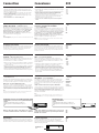
Installation Instalación ###
Precauciones
•No toque los cuatro orificios de la superficie superior de la unidad.
Estos orificios son para ajustes del sintonizador que solamente
deberán realizar técnicos de reparación.
• Para abrir y cerrar el panel frontal, debe haber una distancia de al
menos 5 cm entre la ranura de inserción de cintas de la unidad y la
palanca de cambios. Instale la unidad en un lugar que no entorpezca
las operaciones de cambio de marchas o de conducción en general.
•Elija cuidadosamente el lugar de montaje de forma que la unidad no
interfiera las funciones normales de conducción.
•Evite instalar la unidad donde pueda quedar sometida a altas
temperaturas, como a la luz solar directa o al aire calienete de
calefacción, o a polvo, suciedad, o vibraciones excesivas.
•Para realizar una instalación segura y firme, emplee solamente la
ferretería de montaje suministrada.
Ajuste del ángulo de montaje
Ajuste el ángulo de montaje a menos de 20°.
###
• ###
• ###
• ###
• ###
• ###
• ###
###
###
Shift lever
Palanca de cambios
###
more than 5 cm
más de 5 cm
###
Precautions
•Do not tamper with the four holes on the upper surface of the unit.
They are for tuner adjustments to be done only by service
technicians.
•There must be a distance of at least 5 cm between the cassette slot of
the unit and shift lever to open/close the front panel. Choose the
installation location so that the unit does not interfere with gear
shifting or other driving operations.
•Choose the mounting location carefully so that the unit does not
interfere with the normal driving functions of the driver.
•Avoid installing the unit where it would be subject to high
temperatures, such as from direct sunlight or hot air from the heater,
or where it would be subject to dust, dirt or excessive vibration.
•Use only the supplied mounting hardware for a safe and secure
installation.
Mounting angle adjustment
Adjust the mounting angle to less than 20°.
How to detach and attach the front panel
Be sure to detach the front panel before you start installing the
unit.
To detach
Before detaching the front panel, be sure to press (OFF) first. Press
(RELEASE) to open up the front panel. Then slide the front panel a
little to the left, and pull it off towards you.
To attach
Align part A of the front panel to part B of the unit as illustrated, and
push until it clicks.
###
###
###
####
###
###
####
###
Forma de extraer e instalar el panel frontal
Antes de instalar la unidad, extraiga el panel frontal.
Para extraerlo
Antes de extraer el panel frontal, ceriórese de presionar (OFF). Pulse
(RELEASE) para abrir el panel frontal. A continuación, deslícelo
ligeramente hacia la izquierda y extráigalo tirando hacia fuera.
Para instalarlo
Alinee la parte A del panel con la parte B de la unidad como muestra
la ilustración y, a continuación, ejerza presión hasta oír un chasquido.
To detach
para extraerlo
###
A
RELEASE button
Botón RELEASE
###
OFF button
Botón OFF
####
To attach
para instalarlo
###
Mounting example
Installation in the dashboard
Ejemplo de montaje
Instalación en el salpicadero
###
###
TOP
Dashboard
Salpicadero
###
3
1
First attach 5 to the unit, then insert the
unit into 1.
En primer lugar, fije 5 a la unidad y, a
continuación, inserte ésta en 1.
###
###
With the TOP marking up
Con la marca TOP hacia arriba.
###
182 mm
53 mm
TOP
1
Bend these claws, if
necessary.
Si es necesario, doble estas
uñas.
###
Fire wall
Panel cortafuegos
###
3214
Montaje de la unidad en un automóvil japonés
Usted no podrá instalar esta unidad en algunos sutomóviles japoneses.
En tal caso, consulte a su proveedor Sony.
Mounting the unit in a japanese car
You may not be able to install this unit in some makes of Japanese cars.
In such a case, consult your Sony dealer.
###
#####
#
###
###
Note
To prevent malfunction, install only with the supplied screws 4 and use existing parts
supplied to your car.
Nota
Para evitar que se produzcan fallos, realice la instalación solamente con los tornillos
suministrados 4 y utilice los componentes suministrados para el automóvil.
TOYOTA NISSANto dashboard/center console
al salpicadero/consola central
###
Bracket
Soporte
###
Bracket
Soporte
###
4
max. size 5 × 8 mm
Tamaño máx. 5 × 8 mm
###
4
max. size 5 × 8 mm
Tamaño máx. 5 × 8 mm
###
Bracket
Soporte
###
Bracket
Soporte
###
4
max. size 5 × 8 mm
Tamaño máx. 5 × 8 mm
###
to dashboard/center console
al salpicadero/consola central
###
4
max. size 5 × 8 mm
Tamaño máx. 5 × 8 mm
###
Existing parts supplied to your car
Piezas existentes suministradas con su
automóvil
###
Existing parts supplied to your car
Piezas existentes suministradas con su
automóvil
###
5
2
6
4
4
6
6
4
B

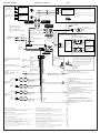
Connection Conexiones ###
###
• ###
• ###
• ###
• ###
• ###
Caution
• This unit is designed for negative earth 12 V DC operation only.
• Before making connections, disconnect the earth terminal of the car
battery to avoid short circuits.
• Connect the yellow and red power input leads only after all other
leads have been connected.
• Be sure to connect the red power input lead to the positive 12 V
power terminal which is energized when the ignition key is in the
accessory position.
• Run all earth wires to a common earth point.
Precauciones
• Esta unidad ha sido diseñada para alimentarse con 12 V CC, negativo
a masa, solamente.
• Antes de realizar las conexiones, desconecte el terminal de puesta a
masa de la batería del automóvil a fin de evitar cortocircuitos.
• Conecte los cables conectores de alimentación amarillo y rojo
solamente después de haber conectado los demás.
• Cerciórese de conectar el cable conector de alimentación rojo a un
terminal de 12 V positivo que se energice al poner la llave de
encendido en la posición para accesorios.
• Conecte todos los conductores de puesta a masa a un punto
común.
If your car has no accessory position on the
ignition key switch
— POWER SELECT switch
The illumination on the front panel is factory-set to be turned on even
when the unit is not being played. However, this setting may cause
some car battery wear if your car has no accessory position on the
ignition key switch. To avoid this battery wear, set the POWER
SELECT switch located on the bottom of the unit to the B
position, then press the reset button. The illumination is reset to
stay off while the unit is not being played.
Note
The caution alarm for the front panel is not activated when the POWER SELECT switch
is set to the B position.
###
— ###
###
###
###
###
###
###
Si el automóvil no dispone de posición para
accesorios en la llave de encendido
— Selector POWER SELECT
La iluminación del panel frontal ha sido ajustada en fábrica para que
esté activada aunque la unidad no se encuentre en reproducción. Sin
embargo, este ajuste puede provocar cierta descarga de la batería del
automóvil si éste no dispone de posición para accesorios en la llave
de encendido. Para evitar esto, ponga el selector POWER SELECT,
situado en la base de la unidad, en la posición B y, después,
presione el botón de reposición. La iluminación estará desactivada
cuando la unidad no se encuentre en reproducción.
Nota
La alarma de precaución del panel frontal no se activará cuando el selector POWER
SELECT se encuentre en la posición B.
Selector de frecuencia
El intervalo de sintonía de AM (FM) ha sido ajustado en fábrica a la
posición 9 K (50 K). Si el sistema de asignación de frecuencias de su
país se basa en el intervalo de 10 kHz (200 kHz), ponga este selector,
situado en la base de la unidad, en la posición 10 K (200 K) antes de
realizar las conexiones.
Frequency select switch
The AM (FM) tuning interval is factory-set to the 9K (50 K) position. If
the frequency allocation system of your country is based on 10 kHz
(200 kHz) interval, set the switch on the bottom of the unit to the
10 K (200 K) position before making connections.
########
######
######
######
Si utiliza el terminal SUB VOLUME OUT/LINE
OUT
— Selector LINE-OUT/IN SELECT
Con el selector LINE-OUT/IN SELECT situado en la base de la
unidad, es posible cambiar el terminal SUB VOLUME OUT/LINE
OUT para que funcione como terminal SUB VOLUME OUT o como
terminal LINE OUT.
•Cuando desee utilizar el terminal SUB VOLUME OUT/LINE OUT
como terminal SUB VOLUME OUT y conectarle un altavoz
potenciador de graves activo, sitúe el selector en la posición 1.
•Cuando desee utilizar el terminal SUB VOLUME OUT/LINE OUT
como terminal LINE OUT y conectarle un procesador de señales
digital o un ecualizador gráfico, sitúe el selector en la posición 2. En
este caso, los terminales FRONT LINE OUT y REAR LINE OUT
actuarán como los terminales FRONT LINE IN y REAR LINE IN
respectivamente.
When using the SUB VOLUME OUT/LINE OUT
terminal
— LINE-OUT/IN SELECT Switch
With the LINE-OUT/IN SELECT switch on the bottom of the unit, you
can change the SUB VOLUME OUT/LINE OUT terminal to work as
SUB VOLUME OUT or as LINE OUT terminal.
•When you want to use the SUB VOLUME OUT/LINE OUT terminal
as SUB VOLUME OUT terminal and connect an active subwoofer to
it, set the switch to 1.
•When you want to use the SUB VOLUME OUT/LINE OUT terminal
as LINE OUT terminal and connect a digital signal processor or
graphic equalizer to it, set the switch to 2. In this case, the FRONT
LINE OUT terminal and REAR LINE OUT terminal will serve as
FRONT LINE IN terminal and REAR LINE IN terminal, respectively.
#############
— ########
#####
#####
#####
• #####
####
•######
#####
When an FM diversity aerial is used
— FM DIVERSITY switch
The unit can be connected with diversity aerials. If you use this unit
with the diversity aerials, set the FM DIVERSITY switch located at the
rear of the unit to the ON position to activate the diversity system.
When you do not use the FM diversity aerials
If you wish to connect a conventional rod aerial, be sure to connect it
to the aerial connector of the unit marked “MAIN”, and set the FM
DIVERSITY switch to the OFF position. Never connect the aerial to the
connector marked “SUB”, otherwise if the FM DIVERSITY switch is set
to the ON position, the radio signals may not be received properly.
Note
The radio reception will be disturbed by noise if the connection of the aerials was not
made properly or the FM DIVERSITY switch was not set correctly.
Cuando utilice antenas de recepción de FM en
diversidad
— Selector FM DIVERSITY
La unidad podrá conectarse a antenas de recepción en diversidad.
Para utilizar esta unidad con antenas de recepción en diversidad,
ponga el interruptor FM DIVERSITY situado en la parte posterior de la
misma en la posición ON a fin de activar el sistema de recepción en
diversidad.
Cuando no utilice antenas de recepción en diversidad
Si desea conectar una antena de telescópica del sistema convencional,
cerciórese de hacerlo al conector de la unidad marcado con “MAIN” y
de poner el interruptor FM DIVERSITY en la posición OFF, No conecte
nunca la antena al conector marcado con “SUB”, porque si el
interruptor FM DIVERSITY estuviese en ON, las señales de radio no se
recibirían adecuadamente.
Nota
La radiorrecepción se verá perturbada por ruido si la conexión de las antenas no fue
realizada adecuadamente o si el interruptor FM DIVERSITY no se encuentra en la
posición correcta.
#############
— ########
##########
#########
###########
#######
#############
ON OFF
DIVERSITY
FM
FM DIVERSITY switch
Selector FM DIVERSITY
#####
Change the position with a jeweler’s screwdriver, etc.
Cambie la posición con un destornillador de relojero, etc.
###
When you change the position of the switch, be sure to press
one of the reset buttons after the connections are completed.
Cuando haya cambiado la posición del selector, cerciórese de
presionar uno de los botones de reposición después de haber
finalizado las conexiones.
###
###
###
Reset button
When the installation and connections are over, be sure to press the
reset button with a ballpoint pen etc. The reset button is located on the
left of the connector on the unit side when the front panel is detached.
Botón de reposición
Cuando haya finalizado la instalación y las conexiones, cerciórese de
presionar el botón de reposición con un boligrafo, etc. El botón de
reposición se encuentra a la izquierda del conector de la parte lateral de la
unidad, detrás del panel frontal.
###
###
###
###
Reset button
Botón de reposición
###
POWER SELECT, Frequency select and LINE-OUT/IN SELECT switch
POWER SELECT, Selector de frecuencia y LINE-OUT/IN SELECT
######
Change the position with a jeweler’s screwdriver, etc.
Cambie la posición con un destornillador de relojero, etc.
###

Connection example Ejemplo de conexiones ###
Active subwoofer
Altavoz potenciador de graves
activo
#####
Front speakers
Altavoces delanteros
###
Source selector
Selector de
fuente
###
XA-C30, etc
*1 BUS cable (not supplied)
Cable BUS (no suministrado)
###
*2 RCA pin cord (not supplied)
Cale con clavijas RCA (no suministrado)
###
Note
Never bundle the inverter’s cord
with any other. It may cause noise.
Nota
No agrupe nunca los cables del
inversor con otro tipo de cables, ya
que puede producirse ruido.
#####
#######
After connecting, bundle up the connecting cord of the rotary
remote with other connecting cords of the audio equipment by
attaching the supplied cramper 0. Be sure to leave some slack
in the connecting cord between the plug and the cramper.
Una vez realizada la conexión, recoja el cable de conexión del
controlador remoto giratorio con el resto de los cables de
conexión del equipo de audio mediante el fijador de cables
suministrado 0. Procure dejar un espacio en el cable de
conexión entre el enchufe y el fijador de cables.
##################
#############
#############
to the interface cable of a car telephone
al cable de interfaz de un teléfono para
automóvil
###
Blue
Azul
###
Max. supply current 0.1 A
Corriente máx. de alimentación de 0,1 A
###
Black
Negro
###
Red
Rojo
###
Yellow
Amarillo
###
Rear speakers
Altavoces traseros
###
Digital pre-amplifier
Preamplificador digital
###
XDP-U50D
RCA pin cord (RC-63 (1 m), RC-64 (2 m) or RC-65 (5 m)) (not
supplied)
Cale con clavijas RCA (RC-63 (1 m), RC-64 (2 m) o RC-65 (5 m))
(no suministrado)
###
###
RCA pin cord (not supplied)
Cale con clavijas RCA (no suministrado)
###
BUS cable (not supplied)
Cable BUS (no suministrado)
###
RCA pin cord (not supplied)
Cale con clavijas RCA (no suministrado)
###
Rotary remote (supplied)
Controlador remoto
giratorio (suministrado)
###
Max. supply current 0.3 A
Corriente máx. de alimentación de
0,3 A
###
AMP REM
ILLUMINATION
Orange/white
striped
Con raya
naranja/blanca
###
TEL MUTE
to car’s illumination signal
a una señal de iluminación del automóvil
###
ANT REM
*2
*1
MAIN ANT
SUB ANT
from car aerial
a la antenna del
automóvil
###
to a remote control lead of the power
amplifier
al conductor de contorol remote del
amplificador de potencia
###
Light blue
Azul celeste
###
Blue/white striped
Azul con raya blanca
###
CD/MD changer
Cambiador de
discos compactos/
minidiscos
###
CD/MD changer
Cambiador de
discos compactos/
minidiscos
###
RCA pin cord (not supplied)
Cale con clavijas RCA (no suministrado)
###
Power amplifier
Amplificador de
potencia
###
Power amplifier
Amplificador de
potencia
###
Fuse (15 A)
Fusible (15 A)
###
7
Left
Lzquierdo
###
Front speakers
Altavoces delanteros
###
Right
Derecho
###
Right
Derecho
###
Left
Lzquierdo
###
Rear speakers
Altavoces traseros
###
to a power aerial relay control box
a la caja de relés de control de la antena motorizada
###
to a metal point of the car
First connect the black earth lead, then connect the yellow and red
power input leads.
a un punto metálico del automóvil
En primer lugar conecte el conductor de puesta a tierra negro y, a
continuación, los cables de entrada de alimentación amarillo y rojo.
###
###
to the +12 V power terminal which is energized in the accessory
position of the ignition key switch
Be sure to connect the black earth lead to it first.
a un terminal de alimentación de +12 V que se energice en la posición
para accesorios de la llave de encendido
Asegúrese de conectar primero a este terminal el conductor de
puesta a masa negro
###
####
to the +12 V power terminal which is energized at all times
Be sure to connect the black earth lead to it first.
a un terminal de alimentación de +12V que esté permanentemente
energizado
Asegúrese de conectar primero a este terminal el conductor de
puesta a masa negro
###
####
Notas sobre los conductores de control
• El conductor de control de la antena motorizada (azul) suministrará +12 V CC
cuando conecte la alimentación del sintonizador o cuando active la función de
activación automática del sintonizador (ATA).
• Con esta unidad no podrá utilizarse una antena motorizada sin caja de relés.
Conexión para protección de la memoria
Si conecta el conductor de entrada amarillo, el circuito de la memoria recibirá siempre
alimentación, incluso aunque ponga la llave de encendido en la posición OFF.
Notas sobre la conexión de los altavoces
• Antes de conectar los altavoces, desconecte la alimentación de la unidad.
• Utilice altavoces con una impedancia de 4 a 8 ohmios, y con la potencia máxima
admisible adecuada, ya que de lo contrario podría dañarlos.
• No conecte los terminales del sistema de altavoces al chasis del automóvil, ni los del
altavoz izquierdo a los del derecho.
• No intente conectar los altavoces en paralelo.
• No conecte altavoces activos (con amplificador incorporado) a los terminales de
altavoces de la unidad. Si lo hiciese, podría dañar tales altavoces. Por lo tanto,
cerciórese de conectar altavoces pasivos a estos terminales.
Notes on the control leads
• The power aerial control lead (blue) supplies +12 V DC when you turn on the tuner
or when you activate the ATA (Automatic Tuner Activation) Function.
• A power aerial without relay box cannot be used with this unit.
Memory hold connection
When the yellow power input lead is connected, power will always be supplied to the
memory circuit even when the ignition key is turned off.
Notes on speaker connection
• Before connecting the speakers, turn the unit off.
• Use speakers with an impedance of 4 to 8 ohms, and with adequate power handling
capacities. Otherwise, the speakers may be damaged.
• Do not connect the terminals of the speaker system to the car chassis, and do not
connect the terminals of the right speaker with those of the left speaker.
• Do not attempt to connect the speakers in parallel.
• Do not connect any active speakers (with built-in amplifiers) to the speaker
terminals of the unit. Doing so may damage the active speakers. Therefore, be sure to
connect passive speakers to these terminals.
###
• ###
###
###
• ###
###
###
###
###
• ###
• ###
###
• ###
###
• ###
• #####
####
##
FRONT LINE OUT/
LINE IN
REAR LINE OUT/
LINE IN
SUB VOLUME
OUT/LINE OUT
When connecting digital pre-amplifier
Conexiónde un preamplificador digital
###
Set the LINE-OUT/IN SELECT switch to
position 2.
Ponga el selector LINE-OUT/IN SELECT en
la posición 2.
###
When connecting two CD/MD changers
Al conectar dos cambiadores de CD/MD
###
BUS CONTROL IN
REMOTE IN
Purple striped
Con raya violeta
###
Green striped
Conraya verde
###
Grey striped
Con raya gris
###
White striped
Con raya blanca
###
!º
BUS AUDIO IN
Inverter
Inversor
######
Transcripción de documentos
Installing the rotary remote Instalación del mando rotavivo Notes • Choose the mounting location carefully so that the rotary remote will not interfere with operating the car. • Do not install the rotary remote in a place where it may jeopardize the safety of the (front) passenger in anyway. • When installing the rotary remote, be sure not to damage the electrical cables etc. on the other side of the mounting surface. • Avoid installing the rotary remote where it may be subject to high temperatures, such as from direct sunlight or hot air from the heater etc. Notas • Elija cuidadosamente el lugar de montaje de forma que el mando rotativo no dificulte la conducción del coche. • No instale el mando rotativo en un lugar donde pueda poner en peligro la seguridad del pasajero acompañante. • Al instalar el mando rotativo, asegúrese de no dañar los cables de electricidad, etc., del otro lado de la superficie de montaje. • Procure no instalar el mando rotativo en un lugar expuesto a altas temperaturas, como a la luz solar directa o al aire caliente de la calefacción, etc. ##### Example of a mounting location Ejemplo de un lugar de montaje ## FM/AM Cassette Car Stereo # • ### • ######## • ######### ### • ######## #### Installation/Connections Instalación/Conexiones ### 1 Choose the exact location for the rotary remote to be mounted, then clean the mounting surface. Dirt or oil impair the adhesive strength of the double-sided adhesive tape. Una vez elegido el lugar de montaje del mando rotativo, limpie previamente la superficie de montaje. La suciedad o la grasa dañan la intensidad adhesiva de la tira adhesiva por las dos caras. ####### ########### 2 Mark two positions for the supplied screws. Use the screw holes on the mounting hardware 9 to mark the positions. 9 Marque dos posiciones para los tornillos suministrados. Para ello, utilice los orificios para tornillos de la ferretería de montaje 9. Marks Marcas ## ####### ########### 3 XR-C800 XR-C800W Remove the steering wheel column cover, and drill 2 mm diameter holes where you have marked. Extraiga la cubierta de la columna de la dirección y haga orificios de 2 mm. de diámetro en los lugares marcados. Sony Corporation 1996 Printed in Japan ######## ### 4 Warm the mounting surface and the double-sided adhesive tape on the mounting hardware 9 to the temperature of 20°C to 30°C, and attach the mounting hardware onto the mounting surface by applying even pressure. Then screw it down with the supplied screws 8. Attach a piece of heavy duty tape etc. on the other side of the mounting surface to cover the protruding tips of the screws so that they will not interfere with the electrical cables etc. inside the steering wheel column. Caliente la superficie de montaje y la cinta adhesiva de doble cara de la ferretería de montaje 9 a una temperatura entre 20°C y 30°C, y ajuste la ferretería de montaje a la superficie de montaje ejerciendo una presión uniforme. A continuación, apriete los tornillos 8 suministrados. Parts for installation and connections Componentes de montaje y conexiones ### 9 The numbers in the list are keyed to those in the instructions. Los números de la lista corresponden a los de las instrucciones. ### 8 µ Heavy duty tape etc. Cinta adhesiva resistente, etc. ##### Adhiera un trozo de cinta adhesiva resistente, etc. en el otro lado de la superficie de montaje para cubrir los extremos de los tornillos que sobresalgan, de forma que no interfieran con los cables de electricidad, etc., del interior de la columna de dirección. P ×1 4 ################ ################ ####### # ###################### ########### 6 ×1 After installing the steering wheel column cover, attach the rotary remote to the mounting hardware by aligning the four holes on the bottom of the rotary remote to the four catches on the mounting hardware and sliding the rotary remote until it locks into place as illustrated. Nota Si monta el mando rotativo en la columna de dirección, asegúrese de que los extremos de los tornillos que sobresalgan de la superficie interior de la columna no dificulten el movimiento del eje de rotación ni los componentes operativos de los conmutadores o los cables de electricidad, etc., del interior de la columna. ×1 5 7 Una vez instalada la cubierta de la columna de dirección, fije el mando rotativo a la ferretería de montaje alineando los cuatro orificios de la parte inferior del mando con los cuatro enganches de la ferretería de montaje. A continuación, deslice el mando hasta que encaje en su sitio como se muestra en la ilustración. ×1 ×5 (incl. 1 reserve) (se incluyen 1 de reserva) ### ########## ######## Note If you are mounting the rotary remote to the steering wheel column, make sure that the protruding tips of the screws on the inner surface of the column do not in anyway hinder or interfere with the movement of the rotating shaft, operative parts of the switches or the electrical cables etc. inside the column. 3 TO ############## ############## ######### 5 2 1 8 ×1 Holes Orificios ## 9 ×2 !º ×1 ×2 ×1 Inverter Inversor •Install the inverter far away from the unit using double-sided adhesive tape or something similar. •Do not bundle the inverter's cord with a pincord or other connecting cord. •Be sure not to mount the inverter under a mat or in a place exposed to splashing water of air conditioner. It may cause electric shock or damage to the unit. •Instale el inversor alejado de la unidad utilizando cinta adhesiva por ambas caras o algo similar. •No bobine el cable del inversor con ning otro cable conector. •Cerciese de no montar el inversor debajo de una alfombrilla ni en un lugar expuesto a salpicaduras de agua de un acondicionador de aire. Esto podr provocar descargas eltricas o dar la unidad. Note If the inverter's cord is pinched, the display indications may not appear. Nota Si el cable del inversor quedase pillado, es posible que no apareciesen las indicaciones del visualizador. ### •### ###. •### ###. •### ###. ### ###. *I-3-858-301-11* (2) Installation Instalación ### Precautions Precauciones ### •Do not tamper with the four holes on the upper surface of the unit. They are for tuner adjustments to be done only by service technicians. •There must be a distance of at least 5 cm between the cassette slot of the unit and shift lever to open/close the front panel. Choose the installation location so that the unit does not interfere with gear shifting or other driving operations. •Choose the mounting location carefully so that the unit does not interfere with the normal driving functions of the driver. •Avoid installing the unit where it would be subject to high temperatures, such as from direct sunlight or hot air from the heater, or where it would be subject to dust, dirt or excessive vibration. •Use only the supplied mounting hardware for a safe and secure installation. •No toque los cuatro orificios de la superficie superior de la unidad. Estos orificios son para ajustes del sintonizador que solamente deberán realizar técnicos de reparación. • Para abrir y cerrar el panel frontal, debe haber una distancia de al menos 5 cm entre la ranura de inserción de cintas de la unidad y la palanca de cambios. Instale la unidad en un lugar que no entorpezca las operaciones de cambio de marchas o de conducción en general. •Elija cuidadosamente el lugar de montaje de forma que la unidad no interfiera las funciones normales de conducción. •Evite instalar la unidad donde pueda quedar sometida a altas temperaturas, como a la luz solar directa o al aire calienete de calefacción, o a polvo, suciedad, o vibraciones excesivas. •Para realizar una instalación segura y firme, emplee solamente la ferretería de montaje suministrada. •### •### •### •### •### •### Mounting angle adjustment Ajuste del ángulo de montaje Adjust the mounting angle to less than 20°. Ajuste el ángulo de montaje a menos de 20°. Shift lever Palanca de cambios ### ### ### more than 5 cm más de 5 cm ### How to detach and attach the front panel Forma de extraer e instalar el panel frontal ### Be sure to detach the front panel before you start installing the unit. Antes de instalar la unidad, extraiga el panel frontal. ### Para extraerlo ### To detach Antes de extraer el panel frontal, ceriórese de presionar (OFF). Pulse (RELEASE) para abrir el panel frontal. A continuación, deslícelo ligeramente hacia la izquierda y extráigalo tirando hacia fuera. Before detaching the front panel, be sure to press (OFF) first. Press (RELEASE) to open up the front panel. Then slide the front panel a little to the left, and pull it off towards you. ### Para instalarlo To attach Align part A of the front panel to part B of the unit as illustrated, and push until it clicks. Alinee la parte A del panel con la parte B de la unidad como muestra la ilustración y, a continuación, ejerza presión hasta oír un chasquido. OFF button Botón OFF #### To detach para extraerlo ### #### ### #### ### To attach para instalarlo ### A B RELEASE button Botón RELEASE ### Mounting example Ejemplo de montaje ### Installation in the dashboard Instalación en el salpicadero ### 1 2 182 3 4 Dashboard Salpicadero ### 1 mm 4 Fire wall Panel cortafuegos ### TO P 5 53 m TO P m 1 2 Bend these claws, if necessary. Si es necesario, doble estas uñas. ### With the TOP marking up Con la marca TOP hacia arriba. ### 6 6 6 4 4 First attach 5 to the unit, then insert the unit into 1. En primer lugar, fije 5 a la unidad y, a continuación, inserte ésta en 1. ### ### Mounting the unit in a japanese car Montaje de la unidad en un automóvil japonés ### You may not be able to install this unit in some makes of Japanese cars. In such a case, consult your Sony dealer. Usted no podrá instalar esta unidad en algunos sutomóviles japoneses. En tal caso, consulte a su proveedor Sony. ##### # TOYOTA to dashboard/center console al salpicadero/consola central ### 4 max. size 5 × 8 mm Tamaño máx. 5 × 8 mm ### 4 NISSAN to dashboard/center console al salpicadero/consola central ### 4 max. size 5 × 8 mm Tamaño máx. 5 × 8 mm ### max. size 5 × 8 mm Tamaño máx. 5 × 8 mm ### Bracket Soporte ### 4 Existing parts supplied to your car Piezas existentes suministradas con su automóvil ### Nota Para evitar que se produzcan fallos, realice la instalación solamente con los tornillos suministrados 4 y utilice los componentes suministrados para el automóvil. max. size 5 × 8 mm Tamaño máx. 5 × 8 mm ### Bracket Soporte ### Bracket Soporte ### Bracket Soporte ### Note To prevent malfunction, install only with the supplied screws 4 and use existing parts supplied to your car. 3 Existing parts supplied to your car Piezas existentes suministradas con su automóvil ### ### ### Connection Conexiones ### Caution Precauciones ### • This unit is designed for negative earth 12 V DC operation only. • Before making connections, disconnect the earth terminal of the car battery to avoid short circuits. • Connect the yellow and red power input leads only after all other leads have been connected. • Be sure to connect the red power input lead to the positive 12 V power terminal which is energized when the ignition key is in the accessory position. • Run all earth wires to a common earth point. • Esta unidad ha sido diseñada para alimentarse con 12 V CC, negativo a masa, solamente. • Antes de realizar las conexiones, desconecte el terminal de puesta a masa de la batería del automóvil a fin de evitar cortocircuitos. • Conecte los cables conectores de alimentación amarillo y rojo solamente después de haber conectado los demás. • Cerciórese de conectar el cable conector de alimentación rojo a un terminal de 12 V positivo que se energice al poner la llave de encendido en la posición para accesorios. • Conecte todos los conductores de puesta a masa a un punto común. • ### • ### • ### • ### • ### If your car has no accessory position on the ignition key switch — POWER SELECT switch Si el automóvil no dispone de posición para accesorios en la llave de encendido ### — Selector POWER SELECT ### ### ### ### The illumination on the front panel is factory-set to be turned on even when the unit is not being played. However, this setting may cause some car battery wear if your car has no accessory position on the ignition key switch. To avoid this battery wear, set the POWER SELECT switch located on the bottom of the unit to the B position, then press the reset button. The illumination is reset to stay off while the unit is not being played. Note The caution alarm for the front panel is not activated when the POWER SELECT switch is set to the B position. La iluminación del panel frontal ha sido ajustada en fábrica para que esté activada aunque la unidad no se encuentre en reproducción. Sin embargo, este ajuste puede provocar cierta descarga de la batería del automóvil si éste no dispone de posición para accesorios en la llave de encendido. Para evitar esto, ponga el selector POWER SELECT, situado en la base de la unidad, en la posición B y, después, presione el botón de reposición. La iluminación estará desactivada cuando la unidad no se encuentre en reproducción. — ### ### ### Nota La alarma de precaución del panel frontal no se activará cuando el selector POWER SELECT se encuentre en la posición B. Frequency select switch Selector de frecuencia ######## The AM (FM) tuning interval is factory-set to the 9K (50 K) position. If the frequency allocation system of your country is based on 10 kHz (200 kHz) interval, set the switch on the bottom of the unit to the 10 K (200 K) position before making connections. El intervalo de sintonía de AM (FM) ha sido ajustado en fábrica a la posición 9 K (50 K). Si el sistema de asignación de frecuencias de su país se basa en el intervalo de 10 kHz (200 kHz), ponga este selector, situado en la base de la unidad, en la posición 10 K (200 K) antes de realizar las conexiones. ###### ###### ###### When using the SUB VOLUME OUT/LINE OUT terminal — LINE-OUT/IN SELECT Switch Si utiliza el terminal SUB VOLUME OUT/LINE OUT — Selector LINE-OUT/IN SELECT ############# With the LINE-OUT/IN SELECT switch on the bottom of the unit, you can change the SUB VOLUME OUT/LINE OUT terminal to work as SUB VOLUME OUT or as LINE OUT terminal. Con el selector LINE-OUT/IN SELECT situado en la base de la unidad, es posible cambiar el terminal SUB VOLUME OUT/LINE OUT para que funcione como terminal SUB VOLUME OUT o como terminal LINE OUT. •When you want to use the SUB VOLUME OUT/LINE OUT terminal as SUB VOLUME OUT terminal and connect an active subwoofer to it, set the switch to 1. •When you want to use the SUB VOLUME OUT/LINE OUT terminal as LINE OUT terminal and connect a digital signal processor or graphic equalizer to it, set the switch to 2. In this case, the FRONT LINE OUT terminal and REAR LINE OUT terminal will serve as FRONT LINE IN terminal and REAR LINE IN terminal, respectively. When an FM diversity aerial is used — FM DIVERSITY switch The unit can be connected with diversity aerials. If you use this unit with the diversity aerials, set the FM DIVERSITY switch located at the rear of the unit to the ON position to activate the diversity system. When you do not use the FM diversity aerials If you wish to connect a conventional rod aerial, be sure to connect it to the aerial connector of the unit marked “MAIN”, and set the FM DIVERSITY switch to the OFF position. Never connect the aerial to the connector marked “SUB”, otherwise if the FM DIVERSITY switch is set to the ON position, the radio signals may not be received properly. Note The radio reception will be disturbed by noise if the connection of the aerials was not made properly or the FM DIVERSITY switch was not set correctly. •Cuando desee utilizar el terminal SUB VOLUME OUT/LINE OUT como terminal SUB VOLUME OUT y conectarle un altavoz potenciador de graves activo, sitúe el selector en la posición 1. •Cuando desee utilizar el terminal SUB VOLUME OUT/LINE OUT como terminal LINE OUT y conectarle un procesador de señales digital o un ecualizador gráfico, sitúe el selector en la posición 2. En este caso, los terminales FRONT LINE OUT y REAR LINE OUT actuarán como los terminales FRONT LINE IN y REAR LINE IN respectivamente. — ######## ##### ##### ##### •##### #### •###### ##### Cuando utilice antenas de recepción de FM en diversidad — Selector FM DIVERSITY ############# La unidad podrá conectarse a antenas de recepción en diversidad. Para utilizar esta unidad con antenas de recepción en diversidad, ponga el interruptor FM DIVERSITY situado en la parte posterior de la misma en la posición ON a fin de activar el sistema de recepción en diversidad. ########## Cuando no utilice antenas de recepción en diversidad — ######## ######### ########### ####### ############# Si desea conectar una antena de telescópica del sistema convencional, cerciórese de hacerlo al conector de la unidad marcado con “MAIN” y de poner el interruptor FM DIVERSITY en la posición OFF, No conecte nunca la antena al conector marcado con “SUB”, porque si el interruptor FM DIVERSITY estuviese en ON, las señales de radio no se recibirían adecuadamente. Nota La radiorrecepción se verá perturbada por ruido si la conexión de las antenas no fue realizada adecuadamente o si el interruptor FM DIVERSITY no se encuentra en la posición correcta. POWER SELECT, Frequency select and LINE-OUT/IN SELECT switch POWER SELECT, Selector de frecuencia y LINE-OUT/IN SELECT ###### FM DIVERSITY switch Selector FM DIVERSITY ##### Change the position with a jeweler’s screwdriver, etc. Cambie la posición con un destornillador de relojero, etc. ### Change the position with a jeweler’s screwdriver, etc. Cambie la posición con un destornillador de relojero, etc. ### When you change the position of the switch, be sure to press one of the reset buttons after the connections are completed. Cuando haya cambiado la posición del selector, cerciórese de presionar uno de los botones de reposición después de haber finalizado las conexiones. ### ### ### Reset button Botón de reposición ### When the installation and connections are over, be sure to press the reset button with a ballpoint pen etc. The reset button is located on the left of the connector on the unit side when the front panel is detached. Cuando haya finalizado la instalación y las conexiones, cerciórese de presionar el botón de reposición con un boligrafo, etc. El botón de reposición se encuentra a la izquierda del conector de la parte lateral de la unidad, detrás del panel frontal. ### ### ### Reset button Botón de reposición ### FM DIVERSITY ON OFF Connection example Rear speakers Altavoces traseros ### Ejemplo de conexiones ### Power amplifier Amplificador de potencia Digital pre-amplifier Preamplificador digital ### ### XDP-U50D Front speakers Altavoces delanteros ### RCA pin cord (not supplied) Cale con clavijas RCA (no suministrado) ### Power amplifier Amplificador de potencia ### ### REAR LINE OUT/ LINE IN FRONT LINE OUT/ LINE IN RCA pin cord (RC-63 (1 m), RC-64 (2 m) or RC-65 (5 m)) (not supplied) Cale con clavijas RCA (RC-63 (1 m), RC-64 (2 m) o RC-65 (5 m)) (no suministrado) ### ### Active subwoofer Altavoz potenciador de graves activo ##### SUB VOLUME OUT/LINE OUT *1 BUS cable (not supplied) Cable BUS (no suministrado) ### *2 RCA pin cord (not supplied) Cale con clavijas RCA (no suministrado) ### Note Never bundle the inverter’s cord with any other. It may cause noise. MAIN ANT from car aerial a la antenna del automóvil ### BUS AUDIO IN Nota No agrupe nunca los cables del inversor con otro tipo de cables, ya que puede producirse ruido. SUB ANT When connecting two CD/MD changers Al conectar dos cambiadores de CD/MD ### RCA pin cord (not supplied) Cale con clavijas RCA (no suministrado) ### Inverter Inversor ###### ##### ####### *2 Source selector Selector de fuente ### *1 BUS cable (not supplied) Cable BUS (no suministrado) ### XA-C30, etc Fuse (15 A) Fusible (15 A) ### REMOTE IN 7 to car’s illumination signal a una señal de iluminación del automóvil ### to a remote control lead of the power amplifier al conductor de contorol remote del amplificador de potencia ### Left Lzquierdo ### Front speakers Altavoces delanteros ### Right Derecho ### Left Lzquierdo ### Rear speakers Altavoces traseros ### Right Derecho ### TEL MUTE Light blue Azul celeste ### ILLUMINATION Orange/white striped Con raya naranja/blanca ### CD/MD changer Cambiador de discos compactos/ minidiscos ### CD/MD changer Cambiador de discos compactos/ minidiscos ### RCA pin cord (not supplied) Cale con clavijas RCA (no suministrado) ### BUS CONTROL IN to the interface cable of a car telephone al cable de interfaz de un teléfono para automóvil ### When connecting digital pre-amplifier Conexiónde un preamplificador digital ### Set the LINE-OUT/IN SELECT switch to position 2. Ponga el selector LINE-OUT/IN SELECT en la posición 2. After connecting, bundle up the connecting cord of the rotary remote with other connecting cords of the audio equipment by attaching the supplied cramper 0. Be sure to leave some slack in the connecting cord between the plug and the cramper. Rotary remote (supplied) Controlador remoto giratorio (suministrado) ### !º Una vez realizada la conexión, recoja el cable de conexión del controlador remoto giratorio con el resto de los cables de conexión del equipo de audio mediante el fijador de cables suministrado 0. Procure dejar un espacio en el cable de conexión entre el enchufe y el fijador de cables. ################## ############# ############# AMP REM Blue/white striped Azul con raya blanca ### Blue Azul ### Max. supply current 0.1 A Corriente máx. de alimentación de 0,1 A ### Max. supply current 0.3 A Corriente máx. de alimentación de 0,3 A ### White striped Con raya blanca ### ANT REM Black Negro ### to a power aerial relay control box a la caja de relés de control de la antena motorizada ### to a metal point of the car First connect the black earth lead, then connect the yellow and red power input leads. a un punto metálico del automóvil En primer lugar conecte el conductor de puesta a tierra negro y, a continuación, los cables de entrada de alimentación amarillo y rojo. ### ### Grey striped Con raya gris ### Red Rojo ### Green striped Conraya verde ### Purple striped Con raya violeta ### to the +12 V power terminal which is energized in the accessory position of the ignition key switch Be sure to connect the black earth lead to it first. a un terminal de alimentación de +12 V que se energice en la posición para accesorios de la llave de encendido Asegúrese de conectar primero a este terminal el conductor de puesta a masa negro ### #### Yellow Amarillo ### to the +12 V power terminal which is energized at all times Be sure to connect the black earth lead to it first. a un terminal de alimentación de +12V que esté permanentemente energizado Asegúrese de conectar primero a este terminal el conductor de puesta a masa negro ### #### Notes on the control leads • The power aerial control lead (blue) supplies +12 V DC when you turn on the tuner or when you activate the ATA (Automatic Tuner Activation) Function. • A power aerial without relay box cannot be used with this unit. Memory hold connection When the yellow power input lead is connected, power will always be supplied to the memory circuit even when the ignition key is turned off. Notes on speaker connection • Before connecting the speakers, turn the unit off. • Use speakers with an impedance of 4 to 8 ohms, and with adequate power handling capacities. Otherwise, the speakers may be damaged. • Do not connect the terminals of the speaker system to the car chassis, and do not connect the terminals of the right speaker with those of the left speaker. • Do not attempt to connect the speakers in parallel. • Do not connect any active speakers (with built-in amplifiers) to the speaker terminals of the unit. Doing so may damage the active speakers. Therefore, be sure to connect passive speakers to these terminals. Notas sobre los conductores de control • El conductor de control de la antena motorizada (azul) suministrará +12 V CC cuando conecte la alimentación del sintonizador o cuando active la función de activación automática del sintonizador (ATA). • Con esta unidad no podrá utilizarse una antena motorizada sin caja de relés. ### • ### ### ### • ### Conexión para protección de la memoria Si conecta el conductor de entrada amarillo, el circuito de la memoria recibirá siempre alimentación, incluso aunque ponga la llave de encendido en la posición OFF. ### ### ### Notas sobre la conexión de los altavoces • Antes de conectar los altavoces, desconecte la alimentación de la unidad. • Utilice altavoces con una impedancia de 4 a 8 ohmios, y con la potencia máxima admisible adecuada, ya que de lo contrario podría dañarlos. • No conecte los terminales del sistema de altavoces al chasis del automóvil, ni los del altavoz izquierdo a los del derecho. • No intente conectar los altavoces en paralelo. • No conecte altavoces activos (con amplificador incorporado) a los terminales de altavoces de la unidad. Si lo hiciese, podría dañar tales altavoces. Por lo tanto, cerciórese de conectar altavoces pasivos a estos terminales. ### • ### • ### ### • ### ### • ### • ##### #### ##-
 1
1
-
 2
2
-
 3
3
-
 4
4


Sony XR-C800 Manual de usuario
- Categoría
- Receptores de medios de coche
- Tipo
- Manual de usuario
- Este manual también es adecuado para
En otros idiomas
- English: Sony XR-C800 User manual
Documentos relacionados
-
Sony XR-C750 Guía de instalación
-
-
-
-
-
-
-
-
-