Senco 100mm nailer SN70 Operating Instructions Manual
- Categoría
- Pistola de clavos
- Tipo
- Operating Instructions Manual
Este manual también es adecuado para

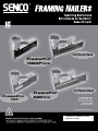
FramePro
®
600
Series
FramePro
®
700XP
Series
Full Round Head
Full Round Head
FramePro
®
721
© 2014 by Senco Brands, Inc.
HVFN020 Revised March 14, 2014
(Replaces 1/30/08)
Senco Brands, Inc.
4270 Ivy Pointe Blvd.
Cincinnati, OH 45245
1-800-543-4596
www.senco.com

TABLE OF
CONTENTS
Tool Use 1
Maintenance 7
Troubleshooting 9
Specications 10
Options 14
Accessories 15
English Español Français
Tool Use Uso de la Herramienta
Utilisation de l’Outil
TABLA DE MATERIAS
Uso de la
Herramienta 1
Mantenimiento 7
Identicación de
Fallas 9
Especicaciones 10
Opciones 14
Accesorios 15
TABLE DES
MATIERÈS
Utilisation de l’outil 1
Entretien 7
Dépannage 9
Spécications 10
Options 14
Accessoires 15
Keep tool pointed away from
yourself and others and connect
air to tool.
Mantenga la herramienta
apuntando en dirección opuesta
de usted y de otros y conecte el
aire a la manguera.
Maintenez l’outil pointé à l’écart
d’autres personnes et de vous-
même et raccordez l’air à l’outil.
Never use a tool that leaks air or
needs repair.
Nunca use una herramienta que
tenga escapes de aire o que
necesite ser reparada.
N’utilisez jamais un outil qui a
des fuites d’air ou qui a besoin
d’être réparé.
English Español Français
2
EMPLOYER’S
RESPONSIBILITIES
Employer must enforce
compliance with the
safety warnings and
all other instructions
which accompany this
tool as shipped from the
manufacturer.
Keep this manual avail-
able for use by all people
assigned to the use of this
tool.
For personal safety and
proper operation of this
tool, read and understand
all of these instructions
carefully.
RESPONSABILIDADES DEL
EMPLEADOR
El empleador debe hacer
cumplir las advertencias de
seguridad y todas las otras
instrucciones que acompañan
a esta herramienta como se la
despacha desde el fabricante.
Mantenga este manual dispo-
nible para que lo usen todas
las personas destinadas a ha-
cer uso de esta herramienta.
Por razones de seguridad per-
sonal y la adecuada operación
de esta herramienta, lea y
comprenda todas estas in-
strucciones cuidadosamente.
RESPONSABILITÉS DE
L’EMPLOYEUR
L’employeur doit faire ap-
pliquer les consignes de
sécurité et toutes les autres
instructions qui accompag-
nent cet outil tel qu’il est
livré par son constructeur.
Ayez ce manuel à la dispo-
sition de toutes les
personnes chargées
d’utiliser cet outil.
Pour assurer la sécu-
rité personnelle et le bon
emploi de cet outil, lisez et
assimilez soigneusement
toutes ces instructions.
Read and understand “SAFETY
INSTRUCTIONS” manual
shipped with this tool before
using tool.
Antes de usar la herramienta lea
y comprenda el manual “INS-
TRUCCIONES DE SEGURI-
DAD” despachado con ella.
Lisez et assimilez le manuel
“INSTRUCTIONS DE SÉCU-
RITÉ” livré avec cet outil avant
de l’utiliser.

3
English Español Français
Tool Use Uso de la Herramienta
Utilisation de l’Outil
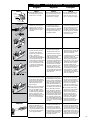
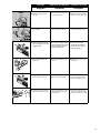
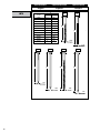
To Load:
Insert strip of nails into rear of
magazine. Use only genuine
SENCO fasteners. Do not load
with safety element or trigger
depressed.
Para cargar:
Inserte la tira de clavos en
la parte de atrás del área de
almacenamiento. Use solamente
sujetadores SENCO auténticos.
No cargue con el disparo o la
seguridad oprimidos.
Pour charger :
Introduisez une bande de clous
dans la partie arrière du maga-
sin. Utilisez uniquement les
véritables clous SENCO. Veillez
à ne pas appuyer sur le palpeur
de sécurité ou sur la détente
quand vous chargez.
Nail Guide (GC0631) should
be installed when driving nails
shorter than 2 1/2" in length.
Se recomienda instalar la Guia
Para Clavos (GC0631) cuando
se pretenda disparar clavos
menores de 2 1/2" de largo.
Le guide clous (GC0631) doit
être installé lorsque l’on veut
passer des clous plus courts
que 2 1/2" (65 mm) en longueur.
To Load:
Position the Nail Guide for the
fastener length. Insert strip of
nails into rear of magazine. Use
only genuine SENCO fasteners.
Do not load with safety mecha-
nism or trigger depressed.
Para cargar:
Coloque la guía del clavo que
corresponda a la longitud del
clavo. Inserte la tira de clavos
en la parte de atrás del área de
almacenamiento. Use solamente
sujetadores SENCO auténticos.
No cargue con el disparo o la
seguridad oprimidos.
Pour charger :
Positionner le guide agrafe pour
la longueur de l’agrafe . Introdui-
sez une bande de clous dans la
partie arrière du magasin. Utilisez
uniquement les clous d‘origine
SENCO. Veillez à ne pas appuyer
sur le palpeur de sécurité ou sur
la détente quand vous chargez.
GC0552
GC0631
GC0547
SN60MC
2 1/2"
2"
1 1/2"
With a Contact Acuation trigger,
nails can be driven two ways:
a) Position safety element
against work surface and pull
trigger...“Trigger Fire.”
b) To drive a nail, pull trigger
and push safety element against
work surface. Each time the
safety element is pushed against
the work surface a nail will be
driven. This “bottom-re” mode
of operation is preferred when
high production, rapid fastener
placement is desired.
Las herramientas con gatillo
de accion doble pueden ser
disparadas de dos maneras:
a) Oprima el seguro contra la
supercie de trabajo y apriete el
gatillo...Disparo de gatillo.
b) Para impulsar un clavo,
oprima el disparador y deprima
el elemento de seguridad contra
la supercie de trabajo. Cada
vez que deprima el elemento de
seguridad contra la supercie
de trabajo, impulsará un clavo.
Este modo de operación de
“disparo inferior” o “por rebote”
es el preferido cuando se desea
alta productividad y rápida colo-
cación del clavo.
Les appareils équipés de
déclenchement “au touché / par
gâchette” peuvent être utilisés
de 2 façons différentes :
a) Déclenchement par “gâchette”
: Appliquer le palpeur de
sécurité de l’appareil à l’endroit
désiré et activer la gâchette.
b)Pour planter un clou, tirez sur
la détente et poussez l’élément
de sécurité contre la surface
de travail. Chaque fois que
l’élément de sécurité est poussé
contre la surface de travail un
clou est planté. Le mode de
fonctionnement en “tir continu”
est préférable si vous désirez
placer des attaches rapidement
avec forte productivité.
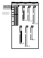
Pull feeder shoe back. Tire la zapata del alimentador. Tirez le poussoir en arrière.
1
2
SN70
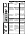
With a Single Sequential trigger,
nails can only be driven one way.
1) First depress safety element
against work surface 2) then pull
trigger. This feature is helpful
when precise fastener place-
ment is required.
Read the “Customer Satisfaction
and Safety Reminder” (CSSR)
in the tool and fastener boxes
for safety information regarding
the Dual Action and Restrictive
triggers. Under certain condi-
tions, the Restrictive trigger may
reduce the possibility of injury
to you or to others working with
you.
Las herramientas con “Ga-
tillo Restringido” solamente se
pueden disparar con el gatillo. 1)
Primero presione el elemento de
seguridad contra la supercie de
trabajo y 2) después apriete el
gatillo. Ésta característica es útil
cuando se requiere precisión en
la colocación de los sujetadores.
Lea el “Recordatorio de Segu-
ridad y Satisfacción del Cliente”
(CSSR) en las cajas de sujeta-
dores y de las herramientas para
información sobre seguridad de
los Gatillos Restringido y de Ac-
ción Dual. Bajo ciertas condicio-
nes, el Gatillo Restringido puede
reducir la posibilidad de heridas a
su persona o a otros que trabajen
con usted.
Avec une gachette “restrictive”,
les clous ne peuvent être tirés
que dans une seule direction. 1)
Appuyer d’abord le palpeur de
sécurité sur la surface de travail,
2) puis tirer sur la gachette.
Cette fonction est utile pour un
placement précis de projectiles.
Lire le “Rappel de Sécurité et
Satisfaction du Client” (CSSR)
dans les boites à outils et
xations pour les informations
de sécurité concernant les
Détentes à Double Action et
à Restriction. Dans certaines
circonstances, la Détente à
Restriction peut réduire la
possibilité de se blesser ou de
blesser d’autres personnes.
SN70 SN70 SN70
FramePro

4
English Español Français
Tool Use Uso de la Herramienta
Utilisation de l’Outil
This tool is equipped with a mov-
able rail safety mechanism. To
activate the tool:
1.) Before each ring, be sure to
position the rst nail through the
hole in the metal connector. If
the nail is not positioned prop-
erly it could ricochet and hurt
someone.
2.) Depress the tool against the
work surface. This will cause the
rail safety mechanism to move
upward. To prevent damaging
nail strips and jamming, do not
push the tool forward when posi-
tioning the rst nail or activating
the tool.
3.) Pull the trigger to activate the
tool.
Esta herramienta esta equipada
con un mecanismo de seguridad
de riel movible:
1.) Antes de cada disparo, ase-
gurese de que el primer clavo
este dentro del oricio de conec-
tor metálico. Si el clavo no está
colocado en el lugar apropiado,
el sujetador puede rebotar y
herir a alguien.
2.) Empuje la herramienta contra
la supercie de trabajo. Esto
hará que el mecanismo de se-
guridad de riel se mueva hacia
arriba. Para prevenir atranca-
miento y daño a las Tiras de cla-
vos, no empuje hacia adelante
cuando apunte el promer clavo o
cuando active la herramienta.
3.) Oprima el gatillo para activar
la herramienta.
Cet outil est équipé d’un mé-
canisme mobile de sécurité sur
le rail. Pour activer l’outil:
1.) Avant chaque tir, être sur de
positionner le premier clou dans
le trou du connecteur métal. Si
le clou n’est pas positionné cor-
rectement, il pourrait ricocher et
blesser quelqu’un.
2.) Appuyer l’outil contre la sur-
face de travail. Cela amènera le
mécanisme de sécurité du rail à
bouger vers le haut. Pour éviter
d’endommager ou de coincer
les rouleaux d’agrafes, ne pas
pousser l’outil vers l’avant en
positionnant ou en actionnant
l’outil.
3.) Tirer la gachette pour activer
l’outil.
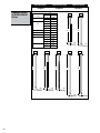
SN60MC
1.
2.
3.
To adjust the depth the fastener
is driven, rst disconnect the air
supply.
Para ajustar la profundidad de
clavo o engrapado, debe primero
desconectar el aire.
Pour ajuster la profondeur à
laquelle le clou est enfoncé, dé-
connecter tout d’abord l’appareil
de la source d’air comprimé.
Using a socket head cap screw
wrench, or a screwdriver, adjust
the safety element to achieve
desired depth.
Con un desarmador o una llave
“Alen” adjuste el seguro para
eduirir la profundidad deseada.
A l’aide d’une clé ou d’un
tournevis, ajuster la position de
l’élément de contact pour obtenir
la pénétration du clou voulue.
Release the feeder shoe
and slide it forward. Remove
fasteners from the tool.
Suelte el alimentador y deslícelo
hacia adelante. Retire los
sujetadores de la herramienta.
Relâcher le poussoir et le faire
glisser vers l’avant. Enlever les
projectiles.
Should a nail jam occur,
disconnect air supply.
Si se produce un altascamiento
de un clavo, desconecte el
suministro de aire.
Au cas ou il se produirait un
coinçage de clous, coupez
l’alimentation en air.
To adjust the depth the fastener
is driven, rst disconnect the air
supply. Using your thumb or index
nger, rotate wheel to adjust the
Depth Control safety element to
achieve desired depth.
Para ajustar la profundidad de
sujetador, dede primero desco-
nectar el aire. Usando el dedo
pulgar o el dedo indice, rote la
manivela para ajustar el seguro a
la profundidad deseada.
Pour ajuster la profondeur à
laquelle le projectile est en-
foncé, déconnecter tout d’abord
l’appareil de la source d’air
comprimé. A l’aide du pouce
ou de l’index, faire tourner la
molette pour ajuster la position
du palpeur de sécurite.
FramePro® XP

5
English Español Français
Tool Use Uso de la Herramienta
Utilisation de l’Outil
SN70
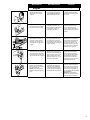
Remove jammed fastener. Close
door and latch.
Remueva el sujetador atascado.
Cierre la puerta con pestillo.
Enlevez le clou coinçé. Fermez
le volet de front et le loquet.
Release E-Z Clear latch and
open door.
Suelte el pestillo de alivio fácil
(E-Z) y abra la puerta.
Relâchez le loquet transparent
“E-Z” et ouvrez le volet de front.
Slide magazine back into posi-
tion and tighten locking knob.
Deslice la carrillera a su posición
original y apriete la manivela.
Glisser le magasin vers sa posi-
tion initiale et resserrer la mo-
lette de verrouillage à la main.
Connect air supply and replace
fasteners. Pull feeder shoe back.
Conecte la línea de aire y reem-
place los clavos. Tire la zapata
del alimentador.
Reconnectez la conduite d’air
comprimé et rechargez le maga-
sin. Tirez le poussoir en arrière.
Clear jammed fastener from
guide body.
Libre el sujetador de la placa
de nariz.
Extraire le clou coincé du front
de l’appareil.
Loosen locking knob at the
rear of the tool by hand. Pull
magazine back.
Desserrer à la main la
molette de verrouillage à
l’arrière de l’outil. Tirer en
arrière le magasin.
Con la mano, aoje la mani-
vela la localizada en la parte
posterior. Empuje y jale la
carrillera hacia atrás.

6
English Español Français
Tool Use Uso de la Herramienta
Utilisation de l’Outil
a) when approximately ve nails
remain in the magazine, the
safety element will be locked in
the undepressed position until
more nails are loaded into the
magazine. (Safety Note: Due
to various nail sizes, tool may
lockout once but still drive a nail
if safety element is depressed
again.)
b) when the magazine is pulled
back, the safety element will be
locked in the undepressed posi-
tion until the magazine is moved
forward and locked into placed.
a) Cuando queden aproxi-
madamente cinco clavos en
el cargador el seguro quedara
en posición inactiva, hasta que
introduzca más clavos en el
cargador (Nota de seguridad:
debido a la variedad de tamanos
de los clavos, la herramienta
se puede desactivar una vez,
pero aún disparar un clavo si se
vuelve a presionar el elemento
de seguridad).
b) Cuando el cargador se jala
hacia atras el seguro quedara
en posición inactiva hasta que el
cargador se mueva hacia adel-
ante y se coloque en su lugar.
a) Quand il reste approximative-
ment cinq projectiles dans le
magasin, l’élément de sécurité
se bloque en position basse
jusqu’à ce que le magasin soit
rechargé. (Note de Sécurité : Du
à la taille diverse des pointes,
l’outil peut se bloquer tout en
étant capable de tirer une pointe
si le palpeur de sécurité est
appuyé.)
b) Quand le magasin est tiré vers
l’arrière, le palpeur de sécurité
se bloque en position basse
jusqu’à ce que le magasin soit
remis en place et enclanché.
The tool can be converted for
non-toenail (at surface) applica-
tions by adding the no-mar pad.
La Herramienta puede ser
convertida para aplicaciones de
clavado no inclinado, agregando
el cojinete no–mar.
Possibilité de modication de
l’appareil, en ajoutant une pro-
tection sur la sécurité, pour des
clouages sur surfaces plates.
FramePro®
This tool is equipped with a lock-
out feature that prevents the tool
from being activated when there
are 6 or less nails in the maga-
zine.The safety mechanism will
be locked in the undepressed
position until more nails are
loaded into the magazine.
Esta herramienta esta equipada
con un seguro que previene
que la herramienta sea activada
cuando la carrillera contenga
menos de 6 clavos. El seguro
se mantendra en la posicion
deprimida hasta que mas clavos
se coloquen en la carrillera.
Cet appareil est équipé d’un
dispositif de blocage qui permet
d’éviter qu’il soit activé lorsqu’il
reste 6 clous ou moins dans le
magasin. Le palpeur de sécurité
sera bloqué en position “repos”
= non enfoncé, jusqu’à ce que
plus de clous aient été placés
dans le magasin.
El deector puede rotarse para
cambiar la dirección del aire
expedido por el moe. Desco-
necte el aire, aoje los tornillos
de la tapa y porte el deector a
la posición deseada. Apriete los
tornillos de la tapa.
Le déecteur peut être orienté
différemment pour changer la
direction de l’échappement d’air.
Déconnecter l’appareil de la
source d’air comprimé, dévisser
la vis de maintien du déecteur
et faire pivoter celui–ci jusqu’à la
position voulue. Resserrer la vis
de maintien.
The deector can be rotated to
change the direction of the ex-
haust air. Disconnect air supply,
loosen cap screw with a socket
head cap screw wrench, and
then rotate deector to desired
location. Tighten cap screw.
6
This tool is equipped with a
lockout feature that prevents the
tool from being activated under
these conditions:
Esta herramienta está equipada
con una función de seguridad
que impide a la misma activarse
en estas condiciones:
Cet outil est équipé d’un disposi-
tif de blocage pour empêcher
l’ouitl d’être activé dans les
conditions suivantes :
FramePro
®
The deector can be rotated
to change the direction of the
exhaust air. Disconnect air sup-
ply, loosen cap screw with a hex
wrench, and then rotate deector
to desired direction. Tighten cap
screw.
El deector puede rotarse para
cambiar la dirección del aire
expedido por el moe. Desco-
necte el aire, aoje los tornillos
de la tapa y rote el deector a la
dirección deseada. Apriete los
tornillos de la tapa.
Le déecteur peut être orienté
différemment pour changer la
direction de l’échappement d’air.
Déconnecter l’appareil de la
source d’air comprimé, dévisser
la vis de maintien du déecteur
et faire pivoter celui–ci jusqu’à la
position voulue. Resserrer la vis
de maintien.
SN60MC

7
Maintenance Maintenimiento
Entretien
All screws should be kept tight.
Loose screws result in unsafe
operation and parts breakage.
Todos los tornillos tienen que
mantenerse apretados. Los
tornillos sueltos pueden producir
una operación no segura y
quebraduras de partes.
Toutes les vis doivent être
maintenues serrées à fond.
Les vis desserrées entraî-
nent un manque de sûreté du
fonctionnement et la rupture de
pièces.
With tool disconnected, make
daily inspection to assure free
movement of safety element
and trigger. Do not use tool if
safety element or trigger sticks
or binds.
Con la herramienta desconecta-
da, haga inspecciones diarias
para asegurar el movimiento
libre del seguro y del gatillo. No
use la herramienta si el seguro o
el gatillo se atoran.
L’outil étant séparé de
l’alimentation en air, effectuez
une inspection journalière pour
assurer le libre mouvement
du palpeur de sécurité et de
la détente. N’utilisez pas l’outil
si le palpeur de sécurité ou la
détente colle ou se coince.
Squirt Senco pneumatic oil (5 to
10 drops) into the air inlet twice
daily (depending on frequency
of tool use). Other oils may dam-
age O-rings and other tool parts.
Aplique aceite neumático
SENCO en la entrada de aire
dos veces al día (dependiendo
en la frecuencia de uso 5 A 10
Gotas). Otros aceites pueden
dañar los anillos en “O” y otras
piezas de la herramienta.
Avec une burette, placer 5 à 10
gouttes d’huile pneumatique
dans l’arrivée d’air deux fois
par jour (dépend de l’intensité
de l’utilisation de l’appareil).
D’autres huiles pourraient en-
dommager les joints toriques et
d’autres pièces de l’outil.
FrançaisEspañol
English
Solamente si es necesario use
soluciones para limpieza no
amablés -NO LA REMOJE.
Precaución: Tales soluciones
pueden dañar los empaques y
otras partes de la herramienta.
Nettoyez l’outil chaque jour à
l’aide d’un chiffon et inspectez-
le pour déceler une éventuelle
usure. Utilisez uniquement des
solvants non inammables en
cas de nécessité-NE LE FAITES
PAS TREMPER !
Attention : De tels produits
peuvent endommager les joints
et autres pièces de l’appareil.
Wipe tool clean daily and inspect
for wear. Use non-ammable
cleaning solutions only if neces-
sary–DO NOT SOAK.
Caution: Such solutions may
damage O-rings and other tool
parts.
Read and understand “SAFETY
INSTRUCTIONS” manual
shipped with this tool before
using tool.
Antes de usar la herramienta lea
y comprenda el manual “INS-
TRUCCIONES DE SEGURI-
DAD” despachado con ella.
Lisez et assimilez le manuel
“INSTRUCTIONS DE SÉCU-
RITÉ” livré avec cet outil avant
de l’utiliser.

8
Notes

SYMPTÔME
Fuite d’air près du sommet
de l’outil / fonctionnement lent.
SOLUTION
Serrez les vis à fond / vériez
l’alimentation en air ou remplacez
les pièces.
SYMPTÔME
Fuite d’air près de la base
de l’outil / retour inadéquat.
SOLUTION
Serrez les vis à fond / nettoyez
l’outil ou remplacez les pièces.
SYMPTÔME
Autres problèmes.
SOLUTION
Prenez contact avec SENCO.
SYMPTOM
Air leak near top of tool /
Sluggish operation
SOLUTION
Verify air supply / tighten screws or
install Repair Kit.
SYMPTOM
Air leak near bottom of tool /
Poor return.
SOLUTION
Clean tool / tighten screws or
install Repair Kit.
SYMPTOM
SOLUTION
Contact SENCO.
Other problems.
SÍNTOMA
El aire se escapa cerca de la parte supe-
rior de la herramienta / Operación lenta.
SOLUCIÓN
Apriete los tornillos / Verique el
suministro de aire o instale el
Juego de Partes.
SÍNTOMA
SOLUCIÓN
El aire se fuga cerca de la parte
inferior de la herramienta / Mal
retorno.
Apriete los tornillos / Limpié la
herramienta o instale el Juego de
Partes.
SÍNTOMA
SOLUCIÓN
Otros problemas.
Póngase en contacto con SENCO.
9
English Español Français
Troubleshooting
Identicación de Fallas
Dépannage
WARNING
Repairs other than those described
here should be performed only by
trained, qualied personnel. Contact
SENCO for information at
1-800-543-4596.
ALERTA
Las reparaciones, fuera de aquellas
descritas aquí, deben de ser lleva-
das a cabo solamente por personal
entrenado y calicado. Póngase
en contacto con SENCO para
información
1-800-543-4596.
AVERTISSEMENT
Les réparations autres que celles
décrites ici doivent être réalisées
uniquement par du personnel
qualié ayant reçu la formation
appropriée. Pour toute information,
prenez contact avec SENCO par té-
léphone en appelant Le Distributeur
agréé.
SN60MC
SN70
FramePro
®
Read and understand “SAFETY
INSTRUCTIONS” manual
shipped with this tool before
using tool.
Antes de usar la herramienta lea
y comprenda el manual “INS-
TRUCCIONES DE SEGURIDAD”
despachado con ella.
Lisez et assimilez le manuel
“INSTRUCTIONS DE SÉCU-
RITÉ” livré avec cet outil avant
de l’utiliser.

10
SN70
English Español Français
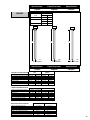
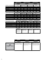
Specications Especicaciones Specications
HCGCGE KC
A A A A
.113"
2,9 mm .113"
2,9 mm
.120"
3 mm .131"
3,3 mm
HF
A
.120"
3 mm
JF
A
.106"
2,7 mm
Code
JF25
GE21
GE24
GC21
GC23
GC24
GC25
HC27
KC27
KC28
KC29
HF27
inches
2 1/2
2
2 3/8
2
2 1/4
2 3/8
2 1/2
3
3
3 1/4
3 1/2
3
A
mm
65
50
60
50
57
60
65
75
75
83
90
75
HCGCGE KC
A A A A
.113"
2,9 mm .113"
2,9 mm
.120"
3 mm .131"
3,3 mm
HF
A
.120"
3 mm
JF
A
.106"
2,7 mm

11
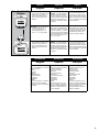
English Español Français
Specications Especicaciones Specications
FramePro® 602/652
100mm & 702XP/
752XP FRH Series
* Rounded to nearest 5 mm
** FramePro 602/702XP only
Code
GL**
GD**
HD
HL
KD
MD
A
FramePro FRH
inches
2
2 3/8
2
2 3/8
2 1/2
3
3 1/4
#4
3
#4
2 1/2
3
3 1/4
3 1/2
#4
2 1/4
3
3 1/4
#4
mm*
50
60
50
60
65
75
83
100
75
100
65
75
83
90
100
57
75
83
100
HDGDGL KD
A A A A
.113"
2,9 mm .113"
2,9 mm
.120"
3,1 mm
.131"
3,3 mm
HL
A
.120"
3,1 mm
D
A
.1"
3, mm
HDGDGL KD
A A A A
.113"
2,9 mm .113"
2,9 mm
.120"
3,1 mm
.131"
3,3 mm
HL
A
.120"
3,1 mm
D
A
.1"
3, mm
# FramePro652 100mm only

12
English Español Français
Specications Especicaciones Specications
FramePro® 601/651
& 701XP/751XP CH
Series
HCGCGE KC
A A A A
.113"
2,9 mm .113"
2,9 mm
.120"
3,1 mm
.131"
3,3 mm
HE
A
.120"
3,1 mm
C
.1"
3, mm
A
H
A
.120"
3,1 mm
Code
GE
GC
HC
HE
HF
KC
MC
inches
2
2 3/8
2
2 1/4
2 3/8
2 1/2
3
3
3
3
3 1/4
3 1/2
3
3 1/4
A
mm
50
60
50
57
60
65
75
75
75
75
83
90
75
83
HCGCGE KC
A A A A
.113"
2,9 mm .113"
2,9 mm
.120"
3,1 mm
.131"
3,3 mm
HE
A
.120"
3,1 mm
C
.1"
3, mm
A
H
A
.120"
3,1 mm

13
English Español Français
Specications Especicaciones Specications
SN60MC
KJ
A
.131"
3,3 mm
MD
A
.148"
3,8 mm
NN
A
.162"
4,1 mm
Code
KJ
MD
NN
inches
1 1/2
1 1/2
2 1/2
2 1/2
A
mm
38
38
65
65
English Español Français
Specications Especicaciones Specications
TECHNICAL SPECIFICATIONS
Minimum to maximum operating pressure
Air Consumption (60 cycles per minute)
Air Inlet
Weight
Fastener Capacity
Tool size: Height
Tool size: Length
Tool size: Width: Main Body
5.5–8.3 bar
231.2 liter
3/8 in. NPT
3.5 kg
30
312 mm
381 mm
111 mm
80–120 psi
8.16scfm
3/8 in. NPT
7.7 lbs.
30
12 5/16 in.
15 in.
4 3/8 in.
SN60MC
4.5–8.3 bar
273.8 liter
3/8 in. NPT
4.4 kg
50-70
373 mm
404 mm
113 mm
65–120 psi
9.67 scfm
3/8 in. NPT
9.7 lbs.
50-70
14.7 in.
15.9 in.
4.5 in.
SN70
ESPECIFICACIONES TECNICAS
Presión de operación mínima y máxima
Consumo de aire (60 ciclos por minuto)
Entrada de aire
Peso
Capacidad de grapas por cargador
Tamaño de la herramienta: Altura
Tamaño de la herramienta: Longitud
Tamaño de la herramienta: Ancho (Cuerpo)
5.5–8.3 bar
231.2 liter
3/8 in. NPT
3.5 kg
30
312 mm
381 mm
111 mm
80–120 psi
8.16scfm
3/8 in. NPT
7.7 lbs.
30
12 5/16 in.
15 in.
4 3/8 in.
SN60MC
4.5–8.3 bar
273.8 liter
3/8 in. NPT
4.4 kg
50-70
373 mm
404 mm
113 mm
65–120 psi
9.67 scfm
3/8 in. NPT
9.7 lbs.
50-70
14.7 in.
15.9 in.
4.5 in.
SN70
SPECIFICATIONS TECHNIQUES
Pression de travail min. et max.
Consommation d’air (60 cycles par minute)
Admission d’air
Poids
Capacité de projectiles par magasin
Dimensions de l’outil: hauteur
Dimensions de l’outil: longueur
Dimensions de l’outil: largeur: corps de l’appareil)
5.5–8.3 bar
231.2 liter
3/8 in. NPT
3.5 kg
30
312 mm
381 mm
111 mm
SN60MC
4.5–8.3 bar
273.8 liter
3/8 in. NPT
4.4 kg
50-70
373 mm
404 mm
113 mm
SN70

CH Model Series
FramePro® 601
FramePro® 701XP
FramePro® 721
FRH Model Series
FramePro® 602
FramePro® 702XP
CH Model Series
FramePro® 651
FramePro® 751XP
FRH Model Series
FramePro® 752XP
**REFERENCE
14
English Español Français
Specications Especicaciones Specications
English Español Français
Options Opciones Options
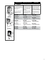
RESTRICTIVE TRIGGER— This
feature is helpful when precise
fastener placement is required.
GATILLO RESTRINGIDO– Esta
característica sirve de ayuda cu-
ando se requiere una colocación
del sujetador precisa.
DECLÉNCHEMENT PAR GA-
CHETTE– Cette caractéristique
s’avère utile quand un placement
de projectiles précis s’impose.
SN70
FramePro® Series
SPECIFICATIONS TECHNIQUES
Pression de travail min. et max.
Consommation d’air (60 cycles par minute)
Admission d’air
Poids
Capacité de projectiles par magasin
Dimensions de l’outil: hauteur
Dimensions de l’outil: longueur
Dimensions de l’outil: largeur: corps de l’appareil)
ESPECIFICACIONES TECNICAS
Presión de operación mínima y máxima
Consumo de aire (60 ciclos por minuto)
Entrada de aire
Peso
Capacidad de grapas por cargador
Tamaño de la herramienta: Altura
Tamaño de la herramienta: Longitud
Tamaño de la herramienta: Ancho (Cuerpo)
TECHNICAL SPECIFICATIONS
Minimum to maximum operating pressure
Air Consumption (60 cycles per minute)
Air Inlet
Weight
Fastener Capacity
Tool size: Height
Tool size: Length
Tool size: Width: Main Body
4.8–8.3 bar
283.2 liter
3/8 in. NPT
3.62 kg
70
337 mm
384 mm
106 mm
FramePro® 651
& 751XP CH Series**
70–120 psi
11 scfm
3/8 in. NPT
8.4 lbs.
70
14 .25 in.
15 .13 in.
4.17 in.
4.8–8.3 bar
311.5 liter
3/8 in. NPT
3.81 kg
70
362 mm
384 mm
106 mm
70–120 psi
10 scfm
3/8 in. NPT
8 lbs.
70
13 .25 in.
15 .13 in.
4.17 in.
FramePro® 601 & 701XP
& 721
FramePro® 602 FRH
& 702XP FRH Series**
70–120 psi
10 scfm
3/8 in. NPT
8.4 lbs.
60
13 .25 in.
20 in.
4.17 in.
4.8–8.3 bar
283.2 liter
3/8 in. NPT
3.81 kg
60
337 mm
508 mm
106 mm
70–120 psi
11 scfm
3/8 in. NPT
8.7 lbs.
60
14 .25 in.
20 in.
4.17 in.
4.8–8.3 bar
311.5 liter
3/8 in. NPT
3.97 kg
60
362 mm
508 mm
106 mm
FramePro® 752XP FRH
Series**
4.8–8.3 bar
283.2 liter
3/8 in. NPT
3.62 kg
70
337 mm
384 mm
106 mm
FramePro® 651
& 751 CH Series**
70–120 psi
11 scfm
3/8 in. NPT
8.4 lbs.
70
14 .25 in.
15 .13 in.
4.17 in.
4.8–8.3 bar
311.5 liter
3/8 in. NPT
3.81 kg
70
362 mm
384 mm
106 mm
70–120 psi
10 scfm
3/8 in. NPT
8 lbs.
70
13 .25 in.
15 .13 in.
4.17 in.
FramePro® 602 FRH
& 702XP FRH Series**
70–120 psi
10 scfm
3/8 in. NPT
8.4 lbs.
60
13 .25 in.
20 in.
4.17 in.
4.8–8.3 bar
283.2 liter
3/8 in. NPT
3.81 kg
60
337 mm
508 mm
106 mm
70–120 psi
11 scfm
3/8 in. NPT
8.7 lbs.
60
14 .25 in.
20 in.
4.17 in.
4.8–8.3 bar
311.5 liter
3/8 in. NPT
3.97 kg
60
362 mm
508 mm
106 mm
FramePro® 752XP FRH
Series**
4.8–8.3 bar
283.2 liter
3/8 in. NPT
3.62 kg
70
337 mm
384 mm
106 mm
FramePro® 651
& 751XP CH Series**
70–120 psi
11 scfm
3/8 in. NPT
8.4 lbs.
70
14 .25 in.
15 .13 in.
4.17 in.
4.8–8.3 bar
311.5 liter
3/8 in. NPT
3.81 kg
70
362 mm
384 mm
106 mm
70–120 psi
10 scfm
3/8 in. NPT
8 lbs.
70
13 .25 in.
15 .13 in.
4.17 in.
FramePro® 602 FRH
& 702XP FRH Series**
70–120 psi
10 scfm
3/8 in. NPT
8.4 lbs.
60
13 .25 in.
20 in.
4.17 in.
4.8–8.3 bar
283.2 liter
3/8 in. NPT
3.81 kg
60
337 mm
508 mm
106 mm
70–120 psi
11 scfm
3/8 in. NPT
8.7 lbs.
60
14 .25 in.
20 in.
4.17 in.
4.8–8.3 bar
311.5 liter
3/8 in. NPT
3.97 kg
60
362 mm
508 mm
106 mm
FramePro® 752XP FRH
Series**
FramePro® 601 & 701XP
& 721
FramePro® 601 & 701XP
& 721

15
SENCO offers a full line of accesso-
ries for your SENCO tools, including:
Air Compressors
Hose
Couplers
Fittings
Safety Glasses
Pressure Gauges
Lubricants
Regulators
Filters
For more information or a complete
illustrated catalogue of SENCO
accessories, ask your representative
for #MK336.
SENCO ofrece una línea completa
de Accesorios para sus herramien-
tas SENCO, incluyendo:
Compresores de Aire
Manguera
Conectores Rapidos
Conectores
Anteojos De Seguridad
Manometros
Lubricantes
Reguladores
Filtros
Para mas informacion ó un pour
recevoir un catalogo completo ilus-
trado de los Accesorios SENCO,
pregunte a su representante pour
el numero #MK336.
SENCO offre une gamme étendue
d’accessoires pour vos outils
SENCO y compris :
Compresseurs
Tuyauterie exible
Raccords
Lunettes de sécurité
Manomètres
Lubriants
Régulateurs
Filtres
Pour plus d’informations ou pour
recevoir un catalogue détaillé des
accessoires proposés par SENCO,
prenez contact avec votre
représentant SENCO (référence
catalogue : #MK336.).
English Español Français
Accessories Accesorios Accessoires
English Español Français
Options Opciones Options
CARRYING CASE — A durable
carrying case is available to help
protect and prolong the life of
the tool. The case can also be
used to carry accessories and
fasteners.
MALETIN PORTA HERRA-
MIENTA — Un maletín durable
esta disponible para ayudarle a
proteger y prolongar la vida de
su herramienta. El maletin puede
también ser usado para llevar
accesorios y sujetadores (clavos
o grapas).
MALETTE DE TRANSPORT
– Une robuste malette est dis-
ponible pour protéger et prolon-
ger la durée de vie de l’appareil.
Elle peut également être utilisée
pour le transport des accessoires
et des projectiles.
PC0678
®
PC0611
R
SN60MC HANGER— Cap can be altered
to attach a hanger. Use a
5/16-18 UNC tap, and drill to a
depth of approximately 1/2 in.
Use a 5/16" x 3 1/8" long eyebolt.
COLGADERO O GANCHO– La
tapa puede ser modicada para
adherirle un colgadero o gancho.
Use una broca de 5/16" - 18 UNC
Y barrene hasta una profundidad
de aproximadamente 1/2" pulgada.
Use un perno de argolla de 5/16"
por 3 1/8" de largo.
SUSPENSION– Le bouchon peut
être modié pour y adapter une
suspension. Percer (13 maxi de
profondeur) et tarauder (M16) à
l’emplacement indiqué, pour y
visser la suspension désirée.
CARRYING CASE — A durable
carrying case is available to help
protect and prolong the life of
the tool. The case can also be
used to carry accessories and
fasteners.
MALETIN PORTA HERRA-
MIENTA — Un maletín durable
esta disponible para ayudarle a
proteger y prolongar la vida de
su herramienta. El maletin puede
también ser usado para llevar
accesorios y sujetadores (clavos
o grapas).
MALETTE DE TRANSPORT
– Une robuste malette est dis-
ponible pour protéger et prolon-
ger la durée de vie de l’appareil.
Elle peut également être utilisée
pour le transport des accessoires
et des projectiles.
FramePro® 600 & 700
CH Series

Limited Warranty
SENCO® Pneumatic, DuraSpin®, Cordless Tools
& Compressors
Senco Products, Inc. (“SENCO”) designs and constructs its products using the highest standards of material and workmanship. SENCO warrants to the original
retail purchaser that the following products will be free from defects in material or workmanship for the warranty period speci ed below:
Pnuematic tools
(both XP and Pro) Fusion Tools Combo Kit Tools GasTools
Five Years Two Years One Year Two Years
Duraspin Tools Air Compressors
Multi-Blow Hand Nailers &
Stapling Hammers
One Year One Year One Year
During the warranty period (which begins on the purchase date), SENCO will repair or replace, at SENCO’s option and expense, any product or part that is defective
in materials or workmanship after examination by a SENCO Authorized Warranty Service Center, subject to the exceptions, exclusions and limitations described below.
Any replacement product or part will carry a warranty for the balance of the warranty period applicable to the replaced product or part. A DATED SALES RECEIPT
OR PROOF OF PURCHASE FROM THE ORIGINAL RETAIL PURCHASER IS REQUIRED TO MAKE A WARRANTY CLAIM. Warranty registration also is required
and can be accomplished through on-line Product Registration at www.senco.com or by completing and returning the postage paid warranty registration form included
with your Operator’s manual/parts chart information, found inside the product carton. To make a warranty claim, you must return the product, with proper receipt/proof
of purchase and return transportation charges prepaid, to a SENCO Authorized Warranty Service Center. A list of SENCO Authorized Warranty Service Centers can
be found at www.senco.com or by calling 1-800-543-4596 toll free. SENCO will perform its obligations under this warranty, within a reasonable time after approval of
the warranty claim.
Wheelbarrow Compressors:
1. Subject to the exceptions, exclusions and limitations described below, SENCO warrants that the compressor pump will be free from defects in materials
and workmanship for two years after the purchase date.
2. Defective parts of the compressor pump not subject to normal wear and tear will be repaired or replaced, at SENCO’s option, during the two year war-
ranty period. If SENCO determines that repair or replacement is not feasible, SENCO will refund the purchase price less reasonable depreciation based
on actual use.
SENCO Cordless:
1. Subject to the exceptions, exclusions and limitations described below, SENCO warrants that the SENCO Cordless tool will be free from defects in materi-
als and workmanship for two years after the purchase date.
2. SENCO warrants that the batteries and chargers used with SENCO Cordless tools will be free from defects in material and workmanship for one year
after the purchase date.
WARRANTY EXCLUSIONS
The following warranty exclusions apply:
1. Normal wear parts are not covered under this warranty. Normal wear parts include, for example, isolators, drive belts, air lters, rubber o-rings, seals,
driver blades, piston stops, and piston/driver assembly.
2. This warranty does not cover parts damaged due to normal wear, misapplication, misuse, accidents, operation at other than recommended speeds or
voltage (electric units only), improper storage, or damage resulting during shipping.
3. Products used in production/industrial applications as de ned by SENCO are excluded from this warranty.
4. Labor charges or loss or damage resulting from improper operation, maintenance or repairs are not covered by this warranty.
5. SENCO does not warrant the Wheelbarrow Compressor Engine/Motor, but the Compressor Engine/Motor may be covered under a warranty offered by its
manufacturer.
GENERAL WARRANTY CONDITIONS
This warranty will be honored, only if:
A. Clean, dry, regulated compressed air has been used, at air pressure not exceeding the maximum indicated on the tool casting;
B. No evidence of abuse, abnormal conditions, accident, neglect, misuse or improper modi cations or storage of the product; and
C. No Deviation from operating instructions, speci cations, and maintenance schedules exists (read Operator Manual for use, speci cations, and mainte-
nance instructions).
THIS WARRANTY IS THE ONLY WARRANTY ON THE PRODUCT, AND SENCO DISCLAIMS ALL OTHER WARRANTIES. ANY IMPLIED WARRANTIES WILL BE
LIMITED IN DURATION TO THE APPLICABLE WARRANTY PERIOD SPECIFIED ABOVE. SOME STATES DO NOT ALLOW LIMITATIONS ON HOW LONG AN
IMPLIED WARRANTY LASTS, SO THE ABOVE LIMITATION MAY NOT APPLY TO YOU. YOUR REMEDIES ARE SOLELY AND EXCLUSIVELY AS STATED ABOVE.
SENCO SHALL IN NO EVENT BE LIABLE FOR INCIDENTAL, CONSEQUENTIAL, INDIRECT, OR SPECIAL DAMAGES. SOME STATES DO NOT ALLOW THE
EXCLUSION OR LIMITATION OF INCIDENTAL OR CONSEQUENTIAL DAMAGES, SO THE ABOVE LIMITATION OR EXCLUSION MAY NOT APPLY TO YOU. IN
NO EVENT, WHETHER AS A RESULT OF A BREACH OF CONTRACT, WARRANTY, TORT (INCLUDING NEGLIGENCE) OR OTHERWISE, SHALL SENCO’S LI-
ABILITY EXCEED THE PRICE OF THE PRODUCT WHICH HAS GIVEN RISE TO THE CLAIM OR LIABILITY. ANY LIABILITY CONNECTED WITH THE USE OF
THIS PRODUCT SHALL TERMINATE UPON THE EXPIRATION OF THE WARRANTY PERIOD SPECIFIED ABOVE. NO EMPLOYEE OR REPRESENTATIVE OF
SENCO OR ANY DISTRIBUTOR OR DEALER IS AUTHORIZED TO MAKE ANY CHANGE OR MODIFICATION TO THIS WARRANTY.
This warranty gives you speci c legal rights, and you may also have other rights which vary from state to state.
REPLACEMENT OF TOOL DUE TO NATURAL DISASTER
SENCO will replace any tool destroyed by an Act of God such as ood, earthquake, hurricane or other disaster resulting only from the forces of nature. Such a claim
will be honored provided that such original retail purchaser had previously submitted a completed warranty registration card for the tool, and then submits proof of
ownership and an acceptable statement describing such Act of God documented by an insurance carrier, police department, or other official governmental source. To
obtain instructions for ling a claim call 1-800-543-4596.
CUSTOMER SATISFACTION
One hundred percent customer satisfaction is our #1 goal. If for any reason the product does not perform to the original purchaser’s satisfaction, it can be returned to
the place of purchase within thirty days with dated sales receipt for a full refund of the purchase price.
© 2013 by SENCO BRANDS, INC.
CINCINNATI, OHIO 45244-1611 USA
www.senco.com
091013
-
 1
1
-
 2
2
-
 3
3
-
 4
4
-
 5
5
-
 6
6
-
 7
7
-
 8
8
-
 9
9
-
 10
10
-
 11
11
-
 12
12
-
 13
13
-
 14
14
-
 15
15
-
 16
16


Senco 100mm nailer SN70 Operating Instructions Manual
- Categoría
- Pistola de clavos
- Tipo
- Operating Instructions Manual
- Este manual también es adecuado para
En otros idiomas
- français: Senco 100mm nailer SN70
- English: Senco 100mm nailer SN70
Documentos relacionados
-
Senco 700XP Series Manual de usuario
-
Senco FramePro 752XP El manual del propietario
-
Senco FramePro 701XP El manual del propietario
-
-
-
-
-
-