Pioneer ND-BC1 Manual de usuario
- Categoría
- Electrónica de vehículos de motor
- Tipo
- Manual de usuario
La página se está cargando...

podría salpicar sobre la misma. (Para evitar el
riego de fallos de funcionamiento producidos por
las altas temperaturas, evite la instalación en los
lugares arriba.)
• Antes de taladrar cualquier orificio de montaje
siempre compruebe lo que hay detrás en donde
desea taladrar los orificios. No taladre en la línea
de combustible, cableado eléctrico u otras partes
importantes.
• Si esta unidad es instalada en el compartimiento
de pasajeros, fíjela seguramente de modo que no
se desprenda mientras el automóvil se encuentra
en movimiento, y pueda ocasionar lesiones o
accidentes.
• Si esta unidad se instale bajo un asiento delantero,
cerciórese de que no obstruye el movimiento del
asiento. Pase todos los cables y conductores
cuidadosamente a través de los mecanismo
deslizantes, de modo que no queden aprisionados
o atrapados en el mecanismo y ocasionen un corto
circuito.
• Encuentre la posición que desea instalar la cámara
de vista posterior. Ajuste el ángulo de la cámara
de vista posterior, e instale de modo que la cámara
no toque el coche.
• Cuando fije a una superficie de vídeo, fíjela en
una posición que asegure que la cámara no toque
la ventana trasera.
• Instale de modo que no obstruya el campo de
vista trasero.
• Instale de modo que no se sobresalga del lado del
coche.
• No realice la instalación en la lluvia o niebla.
• Cuando la humedad está alta, seque la superficie a
la cual fijará la unidad antes de instalar. La
humedad de la superficie de fijación reduce la
resistencia de adherencia, lo que puede soltar la
unidad.
• Si la temperatura de la superficie de fijación está
baja, caliente con un secador de pelo u otro medio
antes de instalar, para mejorar la resistencia de
adherencia.
• No fije el soporte de la cámara en áreas en la
carrocería del coche tratadas con resina de
fluorocarburo, o vidrio. Esto puede resultar en la
caída de la cámara de vista posterior.
• Durante el período de 24 horas tras la instalación:
– No aplique agua a la unidad.
– No exponga la unidad a la lluvia.
– No sujete la cámara a la fuerza innecesaria.
• Limpie completamente el sitio donde se utilizará
la cinta para fijar la unidad.
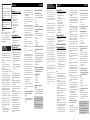
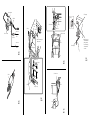
1. Limpie la superficie a la cual se
instalará la cámara de vista
posterior. (Fig. 3)
Utilice un paño u otro ítem para limpiar el
aceite, cera y cualquier otra suciedad de la
superficie de instalación.
2. Alinee el soporte de la cámara con
la superficie de instalación. (Fig. 4)
Ajuste el soporte de la cámara de modo
que no quede ningún espacio entre ello y
la superficie de instalación.
1 Gire
2 Retuerza
3 Soporte de la cámara
3. Fije la cámara de vista posterior al
soporte de la cámara con los
tornillos de instalación. (Fig. 6)
Dependiendo del lado que desea que el
cable salga, páselo a través de la ranura.
1 Parte superior
2 Cámara de vista posterior
3 Parte inferior
4 Tornillo de instalación
5 Soporte de la cámara
4. Quite la hoja de la parte posterior
del soporte de la cámara y fije.
(Fig. 5, Fig. 7)
Presione el soporte de la cámara con los
dedos para fijarlo en la superficie de insta-
lación. Tocar la superficie adhesiva o fijar
la unidad una segunda vez reduce la
resistencia de adherencia, lo que puede
resultar en el despegamiento de la unidad.
1 Soporte de la cámara
2 Fije en el centro
5. Ajuste el ángulo de modo que el
parachoques o borde trasero del
coche se visualice en la parte inferior
de la pantalla de TV. (Fig. 8, Fig. 9,
Fig. 10)
1 Ángulo de visión
Horizontal: 112°
2 Ángulo de visión
Ve rt ic al: 82°
3 Parachoques o borde trasero del coche
6. Instale la unidad de suministro de
energía. (Fig. 11)
Fije la cinta velcro (tipo dura) en la parte
inferior de la unidad de suministro de
energía, y fije la cinta velcro (tipo blanda)
en el sitio de instalación.
• Puede utilizar la cinta velcro (tipo dura) para
fijar directamente a una alfombra, pero no
utilice el tipo de cinta blanda.
• Instale la unidad de suministro de energía lo
suficiente cercano para que el cable de la
cámara de vista posterior la alcance.
• La instalación y cableado de este producto
requiere la habilidad y experiencia de un especia-
lista. Para asegurar la seguridad, solicite un técni-
co especialista para instalar la unidad.
• Este producto es una cámara de vista posterior
para verificar la vista en la parte trasera de un
coche.
Una cámara de vista posterior es una cámara que
provee imágenes simétricas de la misma manera
que los espejos retrovisores o laterales.
• Se puede hacer la conexión a un televisor con
entrada de vídeo RCA, pero compruebe si el tele-
visor tiene una función de conexión de marcha
atrás.
• La luz directa del sol o luz fuerte (luz del sol
reflejada de un parachoques, etc.) en la cámara
puede producir una mancha por encima y por
debajo de la ubicación donde la luz radia, pero
esto no es un fallo de funcionamiento.
• Este producto ha sido diseñado para complementar
la vista trasera del conductor, pero las imágenes de
la cámara no muestran todos los peligros y
obstáculos. Asegúrese de mirar atrás cuando vaya
de marcha atrás para comprobar la vista.
• Este producto tiene una lente de gran angular y,
por lo tanto, la vista cercana es amplia y la vista
distante es estrecha, lo que puede crear una sen-
sación falsa de la distancia. Asegúrese de mirar
atrás cuando vaya de marcha atrás para comprobar
la vista.
• No lave su coche en un túnel de lavado automático
o agua de alta presión, ya que esto puede resultar
en la entrada de agua en la cámara o caída de la
cámara.
•Verifique la instalación del soporte de la cámara
antes de conducir el coche.
¿No están flojos los tornillos?
– ¿Está firmemente fijo el soporte de la cámara?
–Si la cámara de vista posterior se afloja mien-
tras está conduciendo, esto puede causar un
accidente.
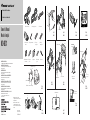
Piezas suministradas
A Cámara de vista posterior × 1
B Unidad de suministro de energía × 1
C Cable RCA × 1
D Soporte de la cámara de vista posterior × 1
E Llave hexagonal × 1
F Cinta velcro (tipo blanda) × 1
G Cinta velcro (tipo dura) × 1
H Tornillos de instalación (3 × 4 mm) × 2
I Almohadilla impermeable × 1
J Abrazadera × 10
K Cinta de doble cara × 1
L Enlace de fijación × 1
Ejemplo de instalación (Fig. 1)
1 Superficie de vidrio
2 Asegúrese de que no toque el limpiador
3 Instale en la pieza central
Cambio de la orientación de la instalación
del soporte de la cámara (Fig. 2)
Cambiar la orientación de la ménsula A de
la instalación del soporte de la cámara per-
mite una gran variedad de posibilidades de
instalación. Cambie de acuerdo con a la
forma de su coche o sitio de instalación.
• Utilice la llave hexagonal para sacar los tornil-
los que fijan las ménsulas A y B del soporte
de la cámara.
• Cambie la orientación de la ménsula A de
instalación y, a continuación, fíjela nueva-
mente con los tornillos.
Nota:
• Antes de finalizar la instalación de la unidad,
conecte el cableado temporariamente,
asegurándose de que todo se encuentra conectado
apropiadamente, y la unidad y el sistema funcionan
apropiadamente.
• Utilice solamente las partes incluídas con la unidad
para asegurar una instalación adecuada. El uso de
partes no autorizadas puede ocasionar fallas de
funcionamiento.
• Si la instalación requiere del taladrado de orificios
u otras modificaciones del vehículo, consulte con
su agente o concesionario más cercano a su
domicilio.
• Instale la unidad en donde no interfiera con el
conductor y no pueda lesionar al pasajero en caso
de una parada repentina, tal como una frenada de
emergencia.
• Cuando monte esta unidad, cerciórese que ninguno
de los cables queda aprisionado entre esta unidad y
accesorios o partes metálicas circundantes.
• No monte esta unidad cerca de la salida del
calefactor, en donde podría ser afectado por el
calor o cerca de las puertas, en donde la lluvia
• Installation and wiring of this product require spe-
cialist skill and experience. To assure your safety,
please request a specialist technician to install the
unit.
•This product is a rear view camera for checking
the view at the rear of a car.
A rear view camera is a camera that provides
symmetrical images in the same way as rear and
side view mirrors.
• Connection to a TV with an RCA video input is
possible, but confirm whether the TV you use has
a reverse gear connection function.
• Direct sunlight or strong light (sunlight reflected
from a bumper etc) on the camera may result in
smear above and below the location where the
light strikes, but this is not a malfunction.
•This product is designed to supplement the dri-
ver’s rear view, but the camera images do not
show all dangers and obstacles. Be sure to look
behind you when reversing to confirm the view.
•This product features a wide-angle lens, so the
near view is wide and the far view is narrow,
which may create a false sense of distance. Be
sure to look behind you when reversing to confirm
the view.
• Do not wash your car with an automatic car wash
or high-pressure water as it may result in water
entering the camera or the camera falling off.
• Check camera stand installation before driving.
Are the screws loose?
– Is the camera stand firmly secured?
– If the rear view camera comes loose while you
are driving it may cause an accident.
Parts supplied
A Rear view camera × 1
B Power supply unit × 1
C RCA cable × 1
D Rear view camera stand × 1
E Hexagon wrench × 1
F Velcro tape (soft type) × 1
G Velcro tape (hard type) × 1
H Installation screws (3 × 4 mm) × 2
I Waterproof pad × 1
J Clamp × 10
K Double-sided tape × 1
L Lock tie × 1
Installation example (Fig. 1)
1 Glass surface
2 Make sure it doesn’t touch the wiper
3 Install on the center part
Changing the orientation of camera
stand installation (Fig. 2)
Changing the orientation of camera stand
installation bracket
A enables a variety of
installation possibilities. Change to match
your car’s shape or the installation site.
• Use the hexagon wrench to remove the
screws securing camera stand brackets
A and B.
• Change the orientation of installation
bracket A, and then secure with the
screws again.
Note:
• Before finally installing the unit, connect the
wiring temporarily, making sure it is all connected
up properly, and the unit and the system work
properly.
• Use only the parts included with the unit to ensure
proper installation. The use of unauthorized parts
can cause malfunctions.
• Consult with your nearest dealer if installation
requires the drilling of holes or other modifica-
tions of the vehicle.
• Install the unit where it does not get in the driver’s
way and cannot injure the passenger if there is a
sudden stop, like an emergency stop.
•When mounting this unit, make sure none of the
leads are trapped between this unit and the sur-
rounding metalwork or fittings.
• Do not mount this unit near the heater outlet,
where it would be affected by heat, or near the
doors, where rainwater might splash onto it.
(Never install in locations such as the above
because of the danger of malfunction due to high
temperatures.)
Installation <ENGLISH>
• Before drilling any mounting holes always check
behind where you want to drill the holes. Do not
drill into the gas line, brake line, electrical wiring
or other important parts.
• If this unit is installed in the passenger compart-
ment, anchor it securely so it does not break free
while the car is moving, and cause injury or an
accident.
• If this unit is installed under a front seat, make
sure it does not obstruct seat movement. Route all
leads and cords carefully around the sliding mech-
anism so they do not get caught or pinched in the
mechanism and cause a short circuit.
• Locate in the position you want to install the rear
view camera. Adjust the angle of the rear view
camera, and install so that the camera doesn’t
touch the car.
•When sticking to a glass surface, stick it on in a
position that assures the camera doesn’t touch the
rear window.
• Install so that it does not obstruct the rear field of
view.
• Install so that it does not protrude from the side of
the car.
• Do not perform installation in rain or fog.
•When humidity is high, dry the surface to which
the unit is to be attached before installing.
Moisture on the attachment surface reduces adhe-
sive strength which may lead to the unit coming
off.
• If the temperature of the attachment surface is
low, warm with a hair dryer of other means before
installing to improve adhesive strength.
• Do not attach the camera stand to areas on the car
body treated with fluorocarbon resin, or glass.
This may result in the rear view camera falling
off.
• During the 24-hour period after installing:
– Do not apply water to the unit.
– Do not expose the unit to rain.
– Do not subject the camera to unnecessary
force.
•Thoroughly clean where tape is used for sticking
on the unit.
1. Clean the surface to which the rear
view camera is to be installed.
(Fig. 3)
Use a cloth or other item to wipe oil, wax,
dust and any other dirt from the installa-
tion surface.
2. Align the camera stand with the
installation surface. (Fig. 4)
Adjust the camera stand so that there is no
space between it and the installation sur-
face.
1 Turn
2 Twist
3 Camera stand
3. Attach the rear view camera to the
camera stand with the installation
screws. (Fig. 6)
Depending on the side you want the cable
to come out of, pass it through the groove.
1 Top
2 Rear view camera
3 Bottom
4 Installation screw
5 Camera stand
4. Peel off the sheet on the back of they
camera stand and stick it on. (Fig. 5,
Fig. 7)
Press the camera stand with your fingers to
stick it to the installation surface. Touching
the adhesive surface or sticking the unit on
a second time reduces adhesive power
which may result in the unit coming off.
1 Camera stand
2 Stick in the center
5. Adjust the angle so that the bumper
or rear edge of the car is displayed
at the bottom of the TV screen.
(Fig. 8, Fig. 9, Fig. 10)
1 Angle of view
Horizontal: 112°
2 Angle of view
Ve rtical: 82°
3 Bumper or rear edge of car
6. Install the power supply unit.
(Fig. 11)
Stick Velcro tape (hard type) to the bottom
of the power supply unit, and stick Velcro
tape (soft type) to the installation site.
•You can use Velcro tape (hard type) to attach
directly to a carpet, but do not use the soft
type.
• Install the power supply unit close enough
for the rear view camera cable to reach.
This device complies with Part 15 of the FCC
Rules.
Operation is subject to the following two condi-
tions:
(1) This device may not cause harmful interference,
and (2) this device must accept any interference
received, including interference that may cause
undesired operation.
Information to User
Alteration or modifications carried out without
appropriate authorization may invalidate the user’s
right to operate the equipment.
WARNING:
Handling the cord on this product or cords associat-
ed with accessories sold with the product will
expose you to lead, a chemical known to the State of
California and other governmental entities to cause
cancer and birth defects or other reproductive harm.
Wash hands after handling.
IMPORTANT
SAFEGUARDS
Instalación <ESPANÕL>
PRECAUCIONES DE
SEGURIDAD IMPORTANTES
La página se está cargando...
La página se está cargando...
La página se está cargando...

Especificaciones <ESPAÑOL>Conexión <ESPAÑOL>
Power source .......................................... 14.4 V DC
(10.8 — 15.1 V allowable)
Grounding system .............................. Negative type
Max. current consumption .......................... 130 mA
Output video ........................................ Mirror image
(for rear view confirmation)
Sensor ............................ 1/4-inch color CCD sensor
No. of pixels ........ 491 (vertical) × 512 (horizontal)
(Effective no. of pixels roughly 250,000)
Lens ........................................................Wide-angle,
focal length f = 1.94 mm, F value 2.8
Angle of view .................... Horizontal: approx. 112º
Ve rtical: approx. 82º
Iris system .......................................... Electronic iris
Scanning system ........................................ Interlace
Synchronizing system ........ Internal synchronization
Signal-to-noise ratio .......................... 40 dB or more
(at the recommended intensity of illumination)
Horizontal resolution ............ Approx. 300 TV lines
Illumination range .......... Approx. 1.5 — 100,000 lux
Image output ...................................... 1 Vp-p (75 Ω)
Operation temperature range .......... –10ºC — +60ºC
+14ºF — +140ºF
Storage temperature range .............. –20ºC — +80ºC
–4ºF — +176ºF
Dimensions
Camera unit .... 50 (W) × 25 (H) × 20.5 (D) mm
2 (W) × 1 (H) × 3/4 (D) in.
Power supply unit
.......................... 70 (W) × 35 (H) × 25 (D) mm
2-3/4 (W) × 1-3/8 (H) × 1 (D) in.
Weight
Camera unit ................................ 120 g (0.3 lbs)
(including the cable)
Power supply .............................. 150 g (0.3 lbs)
(including the power cord)
Note:
Specifications and the design are subject to possible
modification without prior notice due to improve-
ments.
Specifications <ENGLISH>Connection <ENGLISH>
Note:
•This unit is for vehicles with a 12-volt battery and nega-
tive grounding. Before installing it in a recreational vehi-
cle, truck, or bus, check the battery voltage.
•To avoid shorts in the electrical system, be sure to dis-
connect the ≠ battery cable before beginning installa-
tion.
• Refer to the owner’s manual for details on connecting the
other units, then make connections correctly.
• Secure the wiring with cable clamps or adhesive tape. To
protect the wiring, wrap adhesive tape around them
where they lie against metal parts.
• Route and secure all wiring so it cannot touch any mov-
ing parts, such as the gear shift, handbrake and seat rails.
Do not route wiring in places that get hot, such as near
the heater outlet. If the insulation of the wiring melts or
gets torn, there is a danger of the wiring short-circuiting
to the vehicle body.
• Do not shorten any leads.
•Never feed power to other equipment by cutting the insu-
lation of the power supply lead of the unit and tapping
into the lead. The current capacity of the lead will be
exceeded, causing over heating.
•When replacing fuse, be sure to use only fuse of the rat-
ing prescribed on the fuse holder.
•To minimize noise locate the TV antenna cable, radio
antenna cable and RCA cable as far away from each
other as possible.
• Connection to a TV with an RCA video input is possible,
but confirm whether the TV you use has a reverse gear
connection function.
• If this unit is installed in a vehicle that does not have an
ACC (accessory) position on the ignition switch, the red
lead of the unit should be connected to a terminal cou-
pled with ignition switch ON/OFF operations. If this is
not done, the vehicle battery may be drained when you
are away from the vehicle for several hours.
• Cords for this product and those for other products may
be different colors even if they have the same function.
When connecting this product to another product, refer to
the supplied manuals of both products and connect cords
that have the same function.
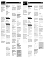
Connection sample (Fig. 12)
1 Power supply unit
2 Rear view camera
Video input jack
Connect to video input jack.
3 RCA cable
Accessory power supply
To electric terminal controlled by ignition
switch (12 V DC) ON/OFF.
4 Red
5 Fuse (1A)
Ground
To vehicle (metal) body.
6 Black
Installation with a lock tie (Fig. 13)
When connecting the rear view camera and
the power supply unit, secure the cord to
the power supply unit with the lock tie.
1 Lock tie
Cord installation (Fig. 14)
1 Clamps
2 Rear view camera
3 RCA cable
4 Product with a video input jack
(Hideaway unit etc.)
5 Power supply unit
6 Made with a rasp etc.
7 Scuff plate
8 Clamp
9 Waterproof plate
Cord installation points (Fig. 15)
•When pulling the cord out of the car,
pull from the outer side of the hatch har-
ness cover and hinge.
1 Pull out from here
2 Hinge
3 Harness cover
4 Rear view camera
5 Hatch
After cord installation (Fig. 16, Fig. 17)
• Open and close the hatch door slowly to
confirm that the cord is not rubbing
against the rim of the door.
1 Rear view camera
2 Hatch
3 Cord
•When the rear view camera cord cannot
be pulled out from the lower side due to
the type of car.
As shown in the figure 17, bend the cord
into a U shape in front of the waterproof
pad, making sure that rain water cannot
enter the car by running down the cord.
1 Clamps
2 Waterproof pad
3 Rubber packing
4 Make a U-shaped loop in the lead outside the
rubber packing to prevent rainwater from
flowing along the lead into the interior of the
vehicle.
No ACC positionACC position
O
N
S
T
A
R
T
O
F
F
A
C
C
O
N
S
T
A
R
T
O
F
F
Fuente de alimentación ............................ CC 14,4 V
10,8 — 15,1 V permisible)
Sistema de conexión a tierra .............. Tipo negativo
Consumo de corriente máx. ........................ 130 mA
Vídeo de salida ............................ Imagen de espejo
(para confirmación de vista posterior)
Sensor .......... Sensor CCD de color de 1/4 pulgadas
No. de píxeles ...... 491 (vertical) × 512 (horizontal)
(No. efectivo de píxeles aproximadamente 250.000)
Lente .................................................. Gran angular,
distancia focal f = 1,94 mm, valor F 2.8
Ángulo de visión.................. Horizontal: aprox. 112º
Ve rtical: aprox. 82º
Sistema de diafragma ............ Diafragma electrónico
Sistema de escaneo ................................ Entrelazado
Sistema de sincronización .... Sincronización interna
Relación señal/ruido ...................... 40 dB o superior
(en la intensidad recomendad de iluminación)
Resolución horizontal ...... Aprox. 300 líneas de TV
Rango de iluminación
...................................... Aprox. 1,5 — 100.000 lux
Salida de imagen ................................ 1 Vp-p (75 Ω)
Rango de temperatura de funcionamiento
...................................................... –10ºC — +60ºC
Rango de temperatura de almacenamiento
...................................................... –20ºC — +80ºC
Dimensiones
Unidad de cámara
.................. 50 (An.) × 25 (Al.) × 20,5 (Pr.) mm
Unidad de suministro de energía
...................... 70 (An.) × 35 (Al.) × 25 (Pr.) mm
Peso
Unidad de cámara
................................ 120 g (incluyendo el cable)
Suministro de energía
................................ 150 g (incluyendo el cable)
Nota:
Las especificaciones y el diseño están sujetos a posi-
bles modificaciones sin previo aviso debido a mejo-
ramientos.
Nota:
•Esta unidad es para vehículos con una batería de 12 voltios y
masa negativa. Antes de montarlo en un autobús, camión o
vehículo de recreación, compruebe el voltaje de la batería.
•Para evitar cortocircuitos en el sistema eléctrico, cerciórese de
desconectar el cable de batería ≠ antes de comenzar la
instalación.
•Para los detalles sobre la conexión a otras unidades, refiérase
al manual del propietario y luego haga las conexiones
correctamente.
•Asegure el cableado con grapas de cable o cinta aisladora.
Para proteger el cableado, envuelva con cinta aisladora
alrededor del cableado en las partes en donde se apoya contra
las partes metálicas.
•Pase y asegure todo el cableado de modo que no toque
ninguna de la partes móviles, tales como engranaje de
cambio, freno de mano y carriles del asiento. No pase el
cableado por lugares que se calientan, tales como cerca una
salida del calefactor. Si la aislación del cableado se derrite o se
rompe, existe el peligro de que el cableado se ponga en
cortocircuito con la carrocería del vehículo.
• No ponga en cortocircuito ninguno de los conductores.
• No alimente otro equipo cortando la aislación del conductor
de suministro de alimentación de la unidad y enrrollando en el
conductor. La capacidad actual del conductor será excedida,
ocasionando sobrecalentamiento.
• Cuando reemplace el fusible, cerciórese de usar solamente el
fusible indicado en el portafusible.
•Para minimizar el ruido, ubique el cable de antena de TV,
cable de antena de radio y cable RCA lo más lejos posible
el uno del otro.
• Se puede hacer la conexión a un televisor con entrada de
vídeo RCA, pero compruebe si el televisor tiene una
función de conexión de marcha atrás.
•Si se instala esta unidad en un vehículo que no tiene una
posición ACC (accesorio) en el interruptor de encendido, el
conductor rojo de la unidad deberá conectarse al terminal
conectado con las operaciones del interruptor de encendido
ON/OFF. Si no se hace esto, la batería del vehículo podría
drenarse cuando usted esté lejos del vehículo por varias horas.
• Los cables para este producto y aquéllas para otros productos
pueden ser de colores diferentes aun si tienen la misma
función. Cuando se conecta este producto a otro, refiérase a
los manuales de ambos productos y conecte los cables que
tienen la misma función.
Muestra de conexión (Fig. 12)
1 Unidad de suministro de energía
2 Cámara de vista posterior
Toma de entrada de vídeo
Conecte a la toma de entrada de vídeo.
3 Cable RCA
Suministro de energía de accesorios
Al terminal de energía eléctrica controlado por el
interruptor de encendido del vehículo (12 V CC) ON/OFF.
4 Rojo
5 Fusible (1A)
Conexión a tierra
A la carrocería del vehículo (parte metálica).
6 Negro
Instalación con un enlace de fijación (Fig. 13)
Cuando conecte la cámara de vista posterior y
la unidad de suministro de energía, fije el
cable a la unidad de suministro de energía con
el enlace de fijación.
1 Enlace de fijación
Instalación del cable (Fig. 14)
1 Abrazaderas
2 Cámara de vista posterior
3 Cable RCA
4 Producto con una toma de entrada de vídeo
(Unidad oculta, etc.)
5 Unidad de suministro de energía
6 Hecho con una escofina, etc.
7 Placa de marca
8 Abrazadera
9 Placa impermeable
Puntos de instalación del cable (Fig. 15)
• Cuando tire del cable del coche, tire del
lado exterior de la cubierta de arnés de la
escotilla y de la bisagra.
1 Tire de aquí
2 Bisagra
3 Cubierta de arnés
4 Cámara de vista posterior
5 Escotilla
Tras la instalación del cable (Fig. 16, Fig. 17)
• Abra y cierre lentamente la puerta de
escotilla para comprobar que el cable no
está frotando contra borde de la puerta.
1 Cámara de vista posterior
2 Escotilla
3 Cable
• Cuando no se puede tirar de la cámara de
vista posterior desde el lado inferior debido
al tipo de coche.
Como se muestra en la figura 17, doble el
cable en una forma de “U” delante de la
almohadilla impermeable, asegurándose de
que el agua de la lluvia no pueda entrar en el
coche bajando corriendo por el cable.
1 Abrazaderas
2 Almohadilla impermeable
3 Empaquetadura de caucho
4 Haga lazo en forma de “U” en el cable fuera
de la empaquetadura de caucho para evitar
que el agua de la lluvia fluya a lo largo del
cable al interior del vehículo.
No en la posición ACCPosición ACC
O
N
S
T
A
R
T
O
F
F
A
C
C
O
N
S
T
A
R
T
O
F
F
La página se está cargando...
La página se está cargando...
Transcripción de documentos
This device complies with Part 15 of the FCC Rules. Operation is subject to the following two conditions: (1) This device may not cause harmful interference, and (2) this device must accept any interference received, including interference that may cause undesired operation. Information to User Alteration or modifications carried out without appropriate authorization may invalidate the user’s right to operate the equipment. WARNING: Handling the cord on this product or cords associated with accessories sold with the product will expose you to lead, a chemical known to the State of California and other governmental entities to cause cancer and birth defects or other reproductive harm. Wash hands after handling. IMPORTANT SAFEGUARDS • Installation and wiring of this product require specialist skill and experience. To assure your safety, please request a specialist technician to install the unit. • This product is a rear view camera for checking the view at the rear of a car. A rear view camera is a camera that provides symmetrical images in the same way as rear and side view mirrors. • Connection to a TV with an RCA video input is possible, but confirm whether the TV you use has a reverse gear connection function. • Direct sunlight or strong light (sunlight reflected from a bumper etc) on the camera may result in smear above and below the location where the light strikes, but this is not a malfunction. • This product is designed to supplement the driver’s rear view, but the camera images do not show all dangers and obstacles. Be sure to look behind you when reversing to confirm the view. • This product features a wide-angle lens, so the near view is wide and the far view is narrow, which may create a false sense of distance. Be sure to look behind you when reversing to confirm the view. • Do not wash your car with an automatic car wash or high-pressure water as it may result in water entering the camera or the camera falling off. • Check camera stand installation before driving. Are the screws loose? – Is the camera stand firmly secured? – If the rear view camera comes loose while you are driving it may cause an accident. Installation Parts supplied A B C D E F G H I J K L Rear view camera × 1 Power supply unit × 1 RCA cable × 1 Rear view camera stand × 1 Hexagon wrench × 1 Velcro tape (soft type) × 1 Velcro tape (hard type) × 1 Installation screws (3 × 4 mm) × 2 Waterproof pad × 1 Clamp × 10 Double-sided tape × 1 Lock tie × 1 Installation example (Fig. 1) 1 Glass surface 2 Make sure it doesn’t touch the wiper 3 Install on the center part Changing the orientation of camera stand installation (Fig. 2) Changing the orientation of camera stand installation bracket A enables a variety of installation possibilities. Change to match your car’s shape or the installation site. • Use the hexagon wrench to remove the screws securing camera stand brackets A and B. • Change the orientation of installation bracket A, and then secure with the screws again. Note: • Before finally installing the unit, connect the wiring temporarily, making sure it is all connected up properly, and the unit and the system work properly. • Use only the parts included with the unit to ensure proper installation. The use of unauthorized parts can cause malfunctions. • Consult with your nearest dealer if installation requires the drilling of holes or other modifications of the vehicle. • Install the unit where it does not get in the driver’s way and cannot injure the passenger if there is a sudden stop, like an emergency stop. • When mounting this unit, make sure none of the leads are trapped between this unit and the surrounding metalwork or fittings. • Do not mount this unit near the heater outlet, where it would be affected by heat, or near the doors, where rainwater might splash onto it. (Never install in locations such as the above because of the danger of malfunction due to high temperatures.) <ENGLISH> • Before drilling any mounting holes always check behind where you want to drill the holes. Do not drill into the gas line, brake line, electrical wiring or other important parts. • If this unit is installed in the passenger compartment, anchor it securely so it does not break free while the car is moving, and cause injury or an accident. • If this unit is installed under a front seat, make sure it does not obstruct seat movement. Route all leads and cords carefully around the sliding mechanism so they do not get caught or pinched in the mechanism and cause a short circuit. • Locate in the position you want to install the rear view camera. Adjust the angle of the rear view camera, and install so that the camera doesn’t touch the car. • When sticking to a glass surface, stick it on in a position that assures the camera doesn’t touch the rear window. • Install so that it does not obstruct the rear field of view. • Install so that it does not protrude from the side of the car. • Do not perform installation in rain or fog. • When humidity is high, dry the surface to which the unit is to be attached before installing. Moisture on the attachment surface reduces adhesive strength which may lead to the unit coming off. • If the temperature of the attachment surface is low, warm with a hair dryer of other means before installing to improve adhesive strength. • Do not attach the camera stand to areas on the car body treated with fluorocarbon resin, or glass. This may result in the rear view camera falling off. • During the 24-hour period after installing: – Do not apply water to the unit. – Do not expose the unit to rain. – Do not subject the camera to unnecessary force. • Thoroughly clean where tape is used for sticking on the unit. 1. Clean the surface to which the rear view camera is to be installed. (Fig. 3) Use a cloth or other item to wipe oil, wax, dust and any other dirt from the installation surface. 2. Align the camera stand with the installation surface. (Fig. 4) Adjust the camera stand so that there is no space between it and the installation surface. 1 Turn 2 Twist 3 Camera stand 3. Attach the rear view camera to the camera stand with the installation screws. (Fig. 6) Depending on the side you want the cable to come out of, pass it through the groove. 1 2 3 4 5 Top Rear view camera Bottom Installation screw Camera stand 4. Peel off the sheet on the back of they camera stand and stick it on. (Fig. 5, Fig. 7) Press the camera stand with your fingers to stick it to the installation surface. Touching the adhesive surface or sticking the unit on a second time reduces adhesive power which may result in the unit coming off. 1 Camera stand 2 Stick in the center 5. Adjust the angle so that the bumper or rear edge of the car is displayed at the bottom of the TV screen. (Fig. 8, Fig. 9, Fig. 10) 1 Angle of view Horizontal: 112° 2 Angle of view Vertical: 82° 3 Bumper or rear edge of car 6. Install the power supply unit. (Fig. 11) Stick Velcro tape (hard type) to the bottom of the power supply unit, and stick Velcro tape (soft type) to the installation site. • You can use Velcro tape (hard type) to attach directly to a carpet, but do not use the soft type. • Install the power supply unit close enough for the rear view camera cable to reach. PRECAUCIONES DE SEGURIDAD IMPORTANTES • La instalación y cableado de este producto requiere la habilidad y experiencia de un especialista. Para asegurar la seguridad, solicite un técnico especialista para instalar la unidad. • Este producto es una cámara de vista posterior para verificar la vista en la parte trasera de un coche. Una cámara de vista posterior es una cámara que provee imágenes simétricas de la misma manera que los espejos retrovisores o laterales. • Se puede hacer la conexión a un televisor con entrada de vídeo RCA, pero compruebe si el televisor tiene una función de conexión de marcha atrás. • La luz directa del sol o luz fuerte (luz del sol reflejada de un parachoques, etc.) en la cámara puede producir una mancha por encima y por debajo de la ubicación donde la luz radia, pero esto no es un fallo de funcionamiento. • Este producto ha sido diseñado para complementar la vista trasera del conductor, pero las imágenes de la cámara no muestran todos los peligros y obstáculos. Asegúrese de mirar atrás cuando vaya de marcha atrás para comprobar la vista. • Este producto tiene una lente de gran angular y, por lo tanto, la vista cercana es amplia y la vista distante es estrecha, lo que puede crear una sensación falsa de la distancia. Asegúrese de mirar atrás cuando vaya de marcha atrás para comprobar la vista. • No lave su coche en un túnel de lavado automático o agua de alta presión, ya que esto puede resultar en la entrada de agua en la cámara o caída de la cámara. • Verifique la instalación del soporte de la cámara antes de conducir el coche. ¿No están flojos los tornillos? – ¿Está firmemente fijo el soporte de la cámara? – Si la cámara de vista posterior se afloja mientras está conduciendo, esto puede causar un accidente. Instalación <ESPANÕL> Piezas suministradas A B C D E F G H I J K L Cámara de vista posterior × 1 Unidad de suministro de energía × 1 Cable RCA × 1 Soporte de la cámara de vista posterior × 1 Llave hexagonal × 1 Cinta velcro (tipo blanda) × 1 Cinta velcro (tipo dura) × 1 Tornillos de instalación (3 × 4 mm) × 2 Almohadilla impermeable × 1 Abrazadera × 10 Cinta de doble cara × 1 Enlace de fijación × 1 Ejemplo de instalación (Fig. 1) • • • 1 Superficie de vidrio 2 Asegúrese de que no toque el limpiador 3 Instale en la pieza central Cambio de la orientación de la instalación del soporte de la cámara (Fig. 2) Cambiar la orientación de la ménsula A de la instalación del soporte de la cámara permite una gran variedad de posibilidades de instalación. Cambie de acuerdo con a la forma de su coche o sitio de instalación. • Utilice la llave hexagonal para sacar los tornillos que fijan las ménsulas A y B del soporte de la cámara. • Cambie la orientación de la ménsula A de instalación y, a continuación, fíjela nuevamente con los tornillos. • • • • • • Nota: • Antes de finalizar la instalación de la unidad, conecte el cableado temporariamente, asegurándose de que todo se encuentra conectado apropiadamente, y la unidad y el sistema funcionan apropiadamente. • Utilice solamente las partes incluídas con la unidad para asegurar una instalación adecuada. El uso de partes no autorizadas puede ocasionar fallas de funcionamiento. • Si la instalación requiere del taladrado de orificios u otras modificaciones del vehículo, consulte con su agente o concesionario más cercano a su domicilio. • Instale la unidad en donde no interfiera con el conductor y no pueda lesionar al pasajero en caso de una parada repentina, tal como una frenada de emergencia. • Cuando monte esta unidad, cerciórese que ninguno de los cables queda aprisionado entre esta unidad y accesorios o partes metálicas circundantes. • No monte esta unidad cerca de la salida del calefactor, en donde podría ser afectado por el calor o cerca de las puertas, en donde la lluvia • • • • podría salpicar sobre la misma. (Para evitar el riego de fallos de funcionamiento producidos por las altas temperaturas, evite la instalación en los lugares arriba.) Antes de taladrar cualquier orificio de montaje siempre compruebe lo que hay detrás en donde desea taladrar los orificios. No taladre en la línea de combustible, cableado eléctrico u otras partes importantes. Si esta unidad es instalada en el compartimiento de pasajeros, fíjela seguramente de modo que no se desprenda mientras el automóvil se encuentra en movimiento, y pueda ocasionar lesiones o accidentes. Si esta unidad se instale bajo un asiento delantero, cerciórese de que no obstruye el movimiento del asiento. Pase todos los cables y conductores cuidadosamente a través de los mecanismo deslizantes, de modo que no queden aprisionados o atrapados en el mecanismo y ocasionen un corto circuito. Encuentre la posición que desea instalar la cámara de vista posterior. Ajuste el ángulo de la cámara de vista posterior, e instale de modo que la cámara no toque el coche. Cuando fije a una superficie de vídeo, fíjela en una posición que asegure que la cámara no toque la ventana trasera. Instale de modo que no obstruya el campo de vista trasero. Instale de modo que no se sobresalga del lado del coche. No realice la instalación en la lluvia o niebla. Cuando la humedad está alta, seque la superficie a la cual fijará la unidad antes de instalar. La humedad de la superficie de fijación reduce la resistencia de adherencia, lo que puede soltar la unidad. Si la temperatura de la superficie de fijación está baja, caliente con un secador de pelo u otro medio antes de instalar, para mejorar la resistencia de adherencia. No fije el soporte de la cámara en áreas en la carrocería del coche tratadas con resina de fluorocarburo, o vidrio. Esto puede resultar en la caída de la cámara de vista posterior. Durante el período de 24 horas tras la instalación: – No aplique agua a la unidad. – No exponga la unidad a la lluvia. – No sujete la cámara a la fuerza innecesaria. Limpie completamente el sitio donde se utilizará la cinta para fijar la unidad. 1. Limpie la superficie a la cual se instalará la cámara de vista posterior. (Fig. 3) Utilice un paño u otro ítem para limpiar el aceite, cera y cualquier otra suciedad de la superficie de instalación. 2. Alinee el soporte de la cámara con la superficie de instalación. (Fig. 4) Ajuste el soporte de la cámara de modo que no quede ningún espacio entre ello y la superficie de instalación. 1 Gire 2 Retuerza 3 Soporte de la cámara 3. Fije la cámara de vista posterior al soporte de la cámara con los tornillos de instalación. (Fig. 6) Dependiendo del lado que desea que el cable salga, páselo a través de la ranura. 1 2 3 4 5 Parte superior Cámara de vista posterior Parte inferior Tornillo de instalación Soporte de la cámara 4. Quite la hoja de la parte posterior del soporte de la cámara y fije. (Fig. 5, Fig. 7) Presione el soporte de la cámara con los dedos para fijarlo en la superficie de instalación. Tocar la superficie adhesiva o fijar la unidad una segunda vez reduce la resistencia de adherencia, lo que puede resultar en el despegamiento de la unidad. 1 Soporte de la cámara 2 Fije en el centro 5. Ajuste el ángulo de modo que el parachoques o borde trasero del coche se visualice en la parte inferior de la pantalla de TV. (Fig. 8, Fig. 9, Fig. 10) 1 Ángulo de visión Horizontal: 112° 2 Ángulo de visión Vertical: 82° 3 Parachoques o borde trasero del coche 6. Instale la unidad de suministro de energía. (Fig. 11) Fije la cinta velcro (tipo dura) en la parte inferior de la unidad de suministro de energía, y fije la cinta velcro (tipo blanda) en el sitio de instalación. • Puede utilizar la cinta velcro (tipo dura) para fijar directamente a una alfombra, pero no utilice el tipo de cinta blanda. • Instale la unidad de suministro de energía lo suficiente cercano para que el cable de la cámara de vista posterior la alcance. OF T T • Cords for this product and those for other products may be different colors even if they have the same function. When connecting this product to another product, refer to the supplied manuals of both products and connect cords that have the same function. Connection sample (Fig. 12) 1 Power supply unit 2 Rear view camera Video input jack Connect to video input jack. 3 RCA cable 6 Black Installation with a lock tie (Fig. 13) When connecting the rear view camera and the power supply unit, secure the cord to the power supply unit with the lock tie. 1 Lock tie Cord installation (Fig. 14) 1 Clamps 2 Rear view camera 3 RCA cable 4 Product with a video input jack (Hideaway unit etc.) 5 Power supply unit 6 Made with a rasp etc. 7 Scuff plate 8 Clamp 9 Waterproof plate Cord installation points (Fig. 15) • When pulling the cord out of the car, pull from the outer side of the hatch harness cover and hinge. 1 Pull out from here 2 Hinge 3 Harness cover 4 Rear view camera 5 Hatch Note: Specifications and the design are subject to possible modification without prior notice due to improvements. • Esta unidad es para vehículos con una batería de 12 voltios y masa negativa. Antes de montarlo en un autobús, camión o vehículo de recreación, compruebe el voltaje de la batería. • Para evitar cortocircuitos en el sistema eléctrico, cerciórese de desconectar el cable de batería ≠ antes de comenzar la instalación. • Para los detalles sobre la conexión a otras unidades, refiérase al manual del propietario y luego haga las conexiones correctamente. • Asegure el cableado con grapas de cable o cinta aisladora. Para proteger el cableado, envuelva con cinta aisladora alrededor del cableado en las partes en donde se apoya contra las partes metálicas. • Pase y asegure todo el cableado de modo que no toque ninguna de la partes móviles, tales como engranaje de cambio, freno de mano y carriles del asiento. No pase el cableado por lugares que se calientan, tales como cerca una salida del calefactor. Si la aislación del cableado se derrite o se rompe, existe el peligro de que el cableado se ponga en cortocircuito con la carrocería del vehículo. • No ponga en cortocircuito ninguno de los conductores. • No alimente otro equipo cortando la aislación del conductor de suministro de alimentación de la unidad y enrrollando en el conductor. La capacidad actual del conductor será excedida, ocasionando sobrecalentamiento. • Cuando reemplace el fusible, cerciórese de usar solamente el fusible indicado en el portafusible. • Para minimizar el ruido, ubique el cable de antena de TV, cable de antena de radio y cable RCA lo más lejos posible el uno del otro. • Se puede hacer la conexión a un televisor con entrada de vídeo RCA, pero compruebe si el televisor tiene una función de conexión de marcha atrás. • Si se instala esta unidad en un vehículo que no tiene una posición ACC (accesorio) en el interruptor de encendido, el conductor rojo de la unidad deberá conectarse al terminal conectado con las operaciones del interruptor de encendido ON/OFF. Si no se hace esto, la batería del vehículo podría drenarse cuando usted esté lejos del vehículo por varias horas. F ACC O OF To vehicle (metal) body. Nota: F O STAR No ACC position Ground Dimensions Camera unit .... 50 (W) × 25 (H) × 20.5 (D) mm 2 (W) × 1 (H) × 3/4 (D) in. Power supply unit .......................... 70 (W) × 35 (H) × 25 (D) mm 2-3/4 (W) × 1-3/8 (H) × 1 (D) in. Weight Camera unit ................................ 120 g (0.3 lbs) (including the cable) Power supply .............................. 150 g (0.3 lbs) (including the power cord) N STAR STAR ACC position 4 Red 5 Fuse (1A) Power source .......................................... 14.4 V DC (10.8 — 15.1 V allowable) Grounding system .............................. Negative type Max. current consumption .......................... 130 mA Output video ........................................ Mirror image (for rear view confirmation) Sensor ............................ 1/4-inch color CCD sensor No. of pixels ........ 491 (vertical) × 512 (horizontal) (Effective no. of pixels roughly 250,000) Lens ........................................................Wide-angle, focal length f = 1.94 mm, F value 2.8 Angle of view .................... Horizontal: approx. 112º Vertical: approx. 82º Iris system .......................................... Electronic iris Scanning system ........................................ Interlace Synchronizing system ........ Internal synchronization Signal-to-noise ratio .......................... 40 dB or more (at the recommended intensity of illumination) Horizontal resolution ............ Approx. 300 TV lines Illumination range .......... Approx. 1.5 — 100,000 lux Image output ...................................... 1 Vp-p (75 Ω) Operation temperature range .......... –10ºC — +60ºC +14ºF — +140ºF Storage temperature range .............. –20ºC — +80ºC –4ºF — +176ºF <ESPAÑOL> STAR F O To electric terminal controlled by ignition switch (12 V DC) ON/OFF. Conexión N O N F ACC N OF • This unit is for vehicles with a 12-volt battery and negative grounding. Before installing it in a recreational vehicle, truck, or bus, check the battery voltage. • To avoid shorts in the electrical system, be sure to disconnect the ≠ battery cable before beginning installation. • Refer to the owner’s manual for details on connecting the other units, then make connections correctly. • Secure the wiring with cable clamps or adhesive tape. To protect the wiring, wrap adhesive tape around them where they lie against metal parts. • Route and secure all wiring so it cannot touch any moving parts, such as the gear shift, handbrake and seat rails. Do not route wiring in places that get hot, such as near the heater outlet. If the insulation of the wiring melts or gets torn, there is a danger of the wiring short-circuiting to the vehicle body. • Do not shorten any leads. • Never feed power to other equipment by cutting the insulation of the power supply lead of the unit and tapping into the lead. The current capacity of the lead will be exceeded, causing over heating. • When replacing fuse, be sure to use only fuse of the rating prescribed on the fuse holder. • To minimize noise locate the TV antenna cable, radio antenna cable and RCA cable as far away from each other as possible. • Connection to a TV with an RCA video input is possible, but confirm whether the TV you use has a reverse gear connection function. • If this unit is installed in a vehicle that does not have an ACC (accessory) position on the ignition switch, the red lead of the unit should be connected to a terminal coupled with ignition switch ON/OFF operations. If this is not done, the vehicle battery may be drained when you are away from the vehicle for several hours. <ENGLISH> OF Accessory power supply Note: Specifications T <ENGLISH> T Connection After cord installation (Fig. 16, Fig. 17) • Open and close the hatch door slowly to confirm that the cord is not rubbing against the rim of the door. 1 Rear view camera 2 Hatch 3 Cord • When the rear view camera cord cannot be pulled out from the lower side due to the type of car. As shown in the figure 17, bend the cord into a U shape in front of the waterproof pad, making sure that rain water cannot enter the car by running down the cord. 1 Clamps 2 Waterproof pad 3 Rubber packing 4 Make a U-shaped loop in the lead outside the rubber packing to prevent rainwater from flowing along the lead into the interior of the vehicle. Posición ACC No en la posición ACC • Los cables para este producto y aquéllas para otros productos pueden ser de colores diferentes aun si tienen la misma función. Cuando se conecta este producto a otro, refiérase a los manuales de ambos productos y conecte los cables que tienen la misma función. Muestra de conexión (Fig. 12) 1 Unidad de suministro de energía 2 Cámara de vista posterior Toma de entrada de vídeo Conecte a la toma de entrada de vídeo. 3 Cable RCA Suministro de energía de accesorios Al terminal de energía eléctrica controlado por el interruptor de encendido del vehículo (12 V CC) ON/OFF. 4 Rojo 5 Fusible (1A) Conexión a tierra A la carrocería del vehículo (parte metálica). 6 Negro Instalación con un enlace de fijación (Fig. 13) Cuando conecte la cámara de vista posterior y la unidad de suministro de energía, fije el cable a la unidad de suministro de energía con el enlace de fijación. 1 Enlace de fijación Instalación del cable (Fig. 14) 1 Abrazaderas 2 Cámara de vista posterior 3 Cable RCA 4 Producto con una toma de entrada de vídeo (Unidad oculta, etc.) 5 Unidad de suministro de energía 6 Hecho con una escofina, etc. 7 Placa de marca 8 Abrazadera 9 Placa impermeable Puntos de instalación del cable (Fig. 15) • Cuando tire del cable del coche, tire del lado exterior de la cubierta de arnés de la escotilla y de la bisagra. 1 Tire de aquí 2 Bisagra 3 Cubierta de arnés 4 Cámara de vista posterior 5 Escotilla Tras la instalación del cable (Fig. 16, Fig. 17) • Abra y cierre lentamente la puerta de escotilla para comprobar que el cable no está frotando contra borde de la puerta. 1 Cámara de vista posterior 2 Escotilla 3 Cable • Cuando no se puede tirar de la cámara de vista posterior desde el lado inferior debido al tipo de coche. Como se muestra en la figura 17, doble el cable en una forma de “U” delante de la almohadilla impermeable, asegurándose de que el agua de la lluvia no pueda entrar en el coche bajando corriendo por el cable. 1 Abrazaderas 2 Almohadilla impermeable 3 Empaquetadura de caucho 4 Haga lazo en forma de “U” en el cable fuera de la empaquetadura de caucho para evitar que el agua de la lluvia fluya a lo largo del cable al interior del vehículo. Especificaciones Fuente de alimentación ............................ CC 14,4 V 10,8 — 15,1 V permisible) Sistema de conexión a tierra .............. Tipo negativo Consumo de corriente máx. ........................ 130 mA Vídeo de salida ............................ Imagen de espejo (para confirmación de vista posterior) Sensor .......... Sensor CCD de color de 1/4 pulgadas No. de píxeles ...... 491 (vertical) × 512 (horizontal) (No. efectivo de píxeles aproximadamente 250.000) Lente .................................................. Gran angular, distancia focal f = 1,94 mm, valor F 2.8 Ángulo de visión .................. Horizontal: aprox. 112º Vertical: aprox. 82º Sistema de diafragma ............ Diafragma electrónico Sistema de escaneo ................................ Entrelazado Sistema de sincronización .... Sincronización interna Relación señal/ruido ...................... 40 dB o superior (en la intensidad recomendad de iluminación) Resolución horizontal ...... Aprox. 300 líneas de TV Rango de iluminación ...................................... Aprox. 1,5 — 100.000 lux Salida de imagen ................................ 1 Vp-p (75 Ω) Rango de temperatura de funcionamiento ...................................................... –10ºC — +60ºC Rango de temperatura de almacenamiento ...................................................... –20ºC — +80ºC <ESPAÑOL> Dimensiones Unidad de cámara .................. 50 (An.) × 25 (Al.) × 20,5 (Pr.) mm Unidad de suministro de energía ...................... 70 (An.) × 35 (Al.) × 25 (Pr.) mm Peso Unidad de cámara ................................ 120 g (incluyendo el cable) Suministro de energía ................................ 150 g (incluyendo el cable) Nota: Las especificaciones y el diseño están sujetos a posibles modificaciones sin previo aviso debido a mejoramientos.-
 1
1
-
 2
2
-
 3
3
-
 4
4
-
 5
5
-
 6
6
-
 7
7
-
 8
8


Pioneer ND-BC1 Manual de usuario
- Categoría
- Electrónica de vehículos de motor
- Tipo
- Manual de usuario
en otros idiomas
- français: Pioneer ND-BC1 Manuel utilisateur
- italiano: Pioneer ND-BC1 Manuale utente
- English: Pioneer ND-BC1 User manual
- Deutsch: Pioneer ND-BC1 Benutzerhandbuch
- português: Pioneer ND-BC1 Manual do usuário
Artículos relacionados
-
Pioneer ND-BC8 Manual de usuario
-
-
Pioneer ND-BC4 Manual de usuario
-
Pioneer ND BC20 PA Instrucciones de operación
-
Pioneer ND-BC6 Manual de usuario
-
-
-
-
-
Pioneer AVHP6600DVD El manual del propietario