Optimus PA-127 Manual de usuario
- Categoría
- Amplificadores de audio
- Tipo
- Manual de usuario
Este manual también es adecuado para

INSTRUCCIONES
DE FUNCIONAMIENTO
OPERATING
INSTRUCTIONS
AMPLIFICADOR
AMPLIFIER
9I010N - v1.0 06/04/2010
Antes de hacer funcionar estos aparatos, lea detenidamente estas instrucciones.
GUÍA DEL USUARIO
OWNER'S MANUAL
PA-247 PA-127
Before operating these unit, please read these instructions.
N.º

2 PA-247 / PA-127 - V 1.0
PA-247 / PA-127
1. INTRODUCCIÓN .................................................3
2. PLACA POSTERIOR..............................................4
2.1. ALIMENTACIÓN CON BATERÍA.......................4
2.2. CONEXIÓN A LA RED DE 230 V.C.A................4
2.3. FUSIBLE DE RED.........................................5
2.4. VENTILADOR (SOLO PA-247) ........................5
2.5. SALIDA DE LÍNEA DE ALTAVOCES..................5
2.5.1. Baja impedancia.............................6
2.5.2. Alta impedancia..............................6
2.6. CONEXIÓN DE LA MASA AL CHASIS...............8
2.7. ENTRADAS DE SEÑAL CONFIGURABLES .........8
2.8. SALIDAS DE SEÑAL DE PREVIO (PRE-OUT).....9
2.9. ENTRADAS DE SEÑAL DE MAIN IN............... 10
3. PLACA DELANTERA ...........................................11
3.1. INDICADOR DE NIVEL................................ 11
3.2. INDICADOR DE PROTECCIÓN...................... 11
3.3 INDICADOR ON/OFF ................................... 11
3.4 INDICADOR DE PRIORIDAD......................... 11
3.5 INTERRUPTOR ON/OFF................................ 12
3.6 CONTROL “MASTER” CANAL DE PRIORIDAD... 12
3.7 CONTROL “MASTER” CANAL DE PROGRAMA ...12
3.8 CONTROLES DE VOLUMEN, GRAVES Y AGUDOS.
..................................................................... 12
4. CIRCUITOS ...................................................... 12
4.1 CIRCUITOS DE PREVIO ...............................12
4.2. CIRCUITO DE CONTROL ............................. 13
4.3. CIRCUITO DE POTENCIA ............................ 14
4.4. CIRCUITO DE SALIDA DE LÍNEAS ................15
5. AJUSTE DEL CONSUMO EN VACÍO....................... 15
6. PROTECCIONES................................................ 16
6.1. PROTECCIONES TÉRMICAS......................... 16
6.2. PROTECCIÓN DE CORTO CIRCUITO/
SOBRECARGA EN LA LÍNEA DE ALTAVOCES ......... 16
6.3. SISTEMA ANTICLIPPING (SÓLO PA-247)....... 16
7. DIAGRAMA DE BLOQUES ................................... 17
8. ESQUEMAS DE APLICACIÓN ...............................18
8.1. ESQUEMA DE APLICACIÓN 1.......................18
8.2. ESQUEMA DE APLICACIÓN 2.......................19
8.3. ESQUEMA DE APLICACIÓN 3.......................20
8.4. ESQUEMA DE APLICACIÓN 4.......................21
8.5. ESQUEMA DE APLICACIÓN 5.......................22
8.6. ESQUEMA DE APLICACIÓN 6.......................23
8.7. ESQUEMA DE APLICACIÓN 7.......................24
8.8. ESQUEMA DE APLICACIÓN 8.......................25
8.9. ESQUEMA DE APLICACIÓN 9 ......................26
9. VISTA EN PLANTA DEL AMPLIFICADOR................. 27
9.1. PA-247 ....................................................27
9.2. PA-127 ....................................................28
10. CARACTERÍSTICAS TÉCNICAS ..........................29
11. GARANTÍA .....................................................30
1. INTRODUCTION..................................................3
2. REAR PANEL.......................................................4
2.1. BATTERY SUPPLY INPUT ..............................4
2.2. CONNECTION TO THE 230 V.A.C. MAINS ........4
2.3. MAINS FUSE...............................................5
2.4. FAN (ONLY PA-247) .....................................5
2.5. LOUDSPEAKERS LINE OUTPUT ......................5
2.5.1. Low impedance ..............................6
2.5.2. High impedance .............................6
2.6. CONNECTION OF THE GROUND TO THE BOX...8
2.7. CONFIGURABLE SIGNAL INPUTS ...................8
2.8. PRE-OUT SIGNAL OUTPUTS ..........................9
2.9. MAIN IN SIGNAL INPUTS............................ 10
3. FRONT PANEL................................................... 11
3.1. LEVEL INDICATOR .................................... 11
3.2. PROTECTION INDICATOR .......................... 11
3.3. ON/OFF INDICATOR .................................. 11
3.4. PRIORITY INDICATOR ................................ 11
3.5. ON/OFF SWITCH ...................................... 12
3.6. PRIORITY CHANNEL MASTER CONTROL ....... 12
3.7. PROGRAM CHANNEL MASTER CONTROL ...... 12
3.8. VOLUME, BASS AND TREBLE CONTROLS ..... 12
4. CIRCUITS ....................................................... 12
4.1. PREAMPLIFIER CIRCUITS ........................... 12
4.2. CONTROL CIRCUIT ................................... 13
4.3. POWER CIRCUIT ...................................... 14
4.4. LINES OUTPUT CIRCUIT ............................15
5. QUIESCENT CONSUMPTION ADJUSTMENT............ 15
6. PROTECTIONS ................................................. 16
6.1. THERMIC PROTECTIONS ............................ 16
6.2. PROTECTION OF SHORT-CIRCUIT /
OVERLOADING ON THE LOUDSPEAKERS LINE .....16
6.3. ANTICLIPPING SYSTEM (ONLY PA-247) ....... 16
7. BLOCK DIAGRAM .............................................. 17
8. APPLICATION DIAGRAMS .................................. 18
8.1. APPLICATION DIAGRAM 1........................... 18
8.2. APPLICATION DIAGRAM 2........................... 19
8.3. APPLICATION DIAGRAM 3........................... 20
8.4. APPLICATION DIAGRAM 4........................... 21
8.5. APPLICATION DIAGRAM 5........................... 22
8.6. APPLICATION DIAGRAM 6........................... 23
8.7. APPLICATION DIAGRAM 7........................... 24
8.8. APPLICATION DIAGRAM 8 .......................... 25
8.9. APPLICATION DIAGRAM 9 .......................... 26
9. PLAN OF THE AMPLIFIERS ................................. 27
9.1. PA-247 .................................................... 27
9.2. PA-127 .................................................... 28
10. TECHNICAL SPECIFICATIONS ........................... 29
11. GUARANTEE ................................................... 31

PA-247 / PA-127
3PA-247 / PA-127 - V 1.0
1. INTRODUCCIÓN
Los Modelos PA-247/PA-127 son amplifi cadores
integrados de potencia de 240 W. R.M.S. v 120 W. R.M.S
respectivamente. Están pensados para ser utilizados
en instalaciones de megafonía, avisos de emergencia,
música ambiental, reproducción de palabra, etc.
El Modelo PA-247 incorpora la utilización de tecnología
MOSFET (Metal Oxid Semiconductor Field Effect
Transistor).
El Modelo PA-127 utiliza transistores de tecnología
bipolar.
Dentro del apartado de protecciones, los dos modelos
incorporan la ya ampliamente experimentada protección
de corto circuito / sobrecarga en la línea de altavoces y
una protección térmica para evitar averías debidas a un
calentamiento excesivo de los componentes; el Modelo
PA-247 incorpora, además, un sistema ANTICLIPPING
que evita una saturación excesiva de la etapa de
potencia y disminuye la distorsión a potencias superiores
a la nominal, aumentando el margen de seguridad de los
altavoces. El Modelo PA-247 incorpora un ventilador para
aumentar la refrigeración.
Estos aparatos disponen de cinco entradas confi gurables
como micrófono, auxiliar de bajo nivel, auxiliar de alto
nivel, con alta y baja impedancia. Cada una de las
entradas se puede confi gurar como programa o como
prioridad. Las entradas confi guradas como prioridad
siguen un orden de preferencia en cascada.
Los modelos PA-247 y PA-127 disponen de una salida de
PROGRAM PRE-OUT de 775 mV (0dBu) y una salida de
PRIORITY PRE-OUT de 775mV (0dBu).
Incorporan dos entradas de MAIN IN, una para programa
y otra para prioridad. Cuando son seleccionadas
mediante el conmutador de LINK correspondiente entran
directamente sobre la etapa de potencia y solo se ven
afectadas por el control de volumen general.
Los botones de los controles de los modelos PA-247 y
PA-127 son extraíbles.
Ocupan tres unidades en armarios rack de 19”
normalizados.
1. INTRODUCTION
The Models PA-247/PA-127 are 240 W. R.M.S. and
120 W. R.M.S power integrated amplifi ers respectively.
They have been designed to be used in public address
installations, emergency pagings, background music,
speech reproduction systems, etc.
The PA-247 model using MOSFET technology (Metal Oxid
Semiconductor Field Effect Transistor).
The Model PA-127 uses bipolar technology transistors.
Regarding the protections, both models include the
so much experienced protections against short-
circuits/overloading in the loudspeakers line, as well
as a thermic protection to avoid damages caused by
overheating; the model PA-247 includes, moreover,
an ANTICLIPPING system that avoids the saturation
of the booster and reduces the distortion beyond the
nominal power, increasing so the loudspeakers security
margin. The model PA-247 includes a fan to increase the
refrigeration.
These units have fi ve inputs confi gurable as microphone,
low level auxiliar, high level auxiliar, with high and low
impedance. Each one of these inputs can be confi gurated
as program or priority. The inputs confi gurated as priority
have the priority in cascade.
The models PA-247 and PA-127 have a 775 mV (0
dBu) PROGRAM PRE-OUT output and a 775 mV (0 dBu)
PRIORITY PRE-OUT output.
They include two MAIN IN inputs, one for program and
the other for priority. When they are selected by the
corresponding LINK switch, they go directly over the
power unit and only the general volume control have
effect on them.
The control switches of the models PA-247 and PA-127
can be taken out.
They occupy three standard 19” rack units.
Fig. 1

4 PA-247 / PA-127 - V 1.0
PA-247 / PA-127
2. PLACA POSTERIOR
1 Alimentación con baterías (Ap. 2.1).
2. Conexión a la red de 230 V.c.a. (Ap. 2.2).
3. Fusible de red (Ap. 2.3).
4. Conexión de la masa al chasis (Ap. 2.6).
5. Toma de tierra.
6. Ventilador (Solo PA-247) (Ap. 2.4).
7. Salida línea de altavoces (Ap. 2.5).
8. Entradas de MAIN IN. (Ap. 2.9).
9. Salidas de señal de previo (PRE-OUT). (Ap. 2.8).
10. Entradas de señal confi gurables. (Ap. 2.7).
11. Confi guración de entradas (Ap. 2.7).
12. Selectores de LINK. (Ap. 2.9).
13. Relé auxiliar de seguridad de avisos (Ap. 2.5).
2.1. ALIMENTACIÓN CON BATERÍA
Esta alimentación permite el uso de estos aparatos en
instalaciones de seguridad, conectando una batería
de 24 V.C.C. El interruptor ON/OFF no interrumpe la
alimentación de batería.
La intensidad absorbida de la batería a máxima potencia
es:
PA-127: 8 A
PA-247: 19,5 A
2.2. CONEXIÓN A LA RED DE 230 V.C.A.
En la placa posterior, dispone de una base de alimentación
macho CEE 22 que nos permite conectarlo a la red
mediante el cable suministrado con el amplifi cador.
El diseño del transformador de alimentación permite
la utilización de diferentes tensiones de red. Estos
amplifi cadores salen de fabrica preparados para trabajar
con una tensión de red de 230 V.c.a. Bajo demanda
se pueden suministrar preparados para otros tipos de
voltaje.
2. REAR PANEL
1. Battery supply input (Sec. 2.1).
2. Connection to 230 V.a.c. mains. (Sec. 2.2).
3. Mains fuse (Sec. 2.3).
4. Connection of the ground to the box (Sec. 2.6).
5. Earth link.
6. Fan (Only PA-247) (Sec. 2.4).
7. Loudspeakers line output (Sec. 2.5).
8. MAIN IN inputs. (Sec. 2.9).
9. PRE-OUT signal outputs. (Sec. 2.8).
10. Confi gurable signal inputs. (Sec. 2.7).
11. Confi guration of the inputs (Sec. 2.7).
12. LINK selectors. (Sec. 2.9).
13. Security paging auxiliary relay (Sec. 2.5).
2.1. BATTERY SUPPLY INPUT
It allows to use these units in security installations,
by connecting a 24 V.d.c. battery. The ON/OFF switch
doesn’t cut the battery supply.
The intensity absorbed from the battery at maximum
power is:
PA-127: 8A
PA-247: 19,5 A
2.2. CONNECTION TO THE 230 V.A.C.
MAINS
In the rear panel there is a CEE 22 male base for the
supply, that allows to connect it to the mains by means
of the cable supplied together.
The design of the supply transformer makes sure the
using of different tensions of the mains. These amplifi ers
are supplied to work on a 230 V.c.a. Upon specifi c
request, they can also be supplied prepared to work on
other voltages.
Fig. 2

PA-247 / PA-127
5PA-247 / PA-127 - V 1.0
2.3. MAINS FUSE
It is of 6 Ampers in the PA-247 and of 2 Ampers in the
PA-127. In both, it is located into the box below the
supply base. There is also a spare fuse in the same base.
2.4. FAN (ONLY PA-247)
It is activated when the temperature inside the
amplifi er reaches 60º C. To make it well working, it
is advisable to not obstruct the air fl ow as well as
the lateral and underside air points of the frame.
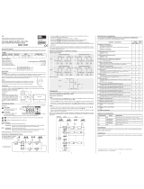
2.5. LOUDSPEAKERS LINE OUTPUT
The contacts used by this output do also include the ones
for the Security Paging. (See Fig. 3).
The loudspeakers line output is made by means of a
transformer with low impedance (4-8-16 ohms) and
constant voltage (50-70- 100 V.) outputs. The connection
is made between the terminal “On (common) and the
corresponding to the choosen impedance or voltage.
2.3. FUSIBLE DE RED
En el PA-247 el fusible es de 6 Amperios y en el PA-
127 es de 2 Amperios. En ambos casos está situado en
el cajón inferior de la base de alimentación de red. Se
suministra también un fusible de recambio en la misma
caja.
2.4. VENTILADOR (SOLO PA-247)
Se activa cuando la temperatura interna del amplifi cador
supera los 60” C. Para un buen funcionamiento del
sistema, es necesario evitar la obstrucción de la salida
de aire del ventilador y las tomas de aire situadas en los
laterales y debajo del aparato.
2.5. SALIDA DE LÍNEA DE ALTAVOCES
Esta salida utiliza una regleta de contactos que además
incluye los del Relé de Seguridad de Avisos. (Ver Fig.
3).
La salida de línea de altavoces se efectúa mediante
un transformador que dispone de salidas de baja
impedancia (4-8-16 ohms) y de alta impedancia (50-70-
100 V.). La conexión tiene que hacerse entre el terminal
“0 (common) y el que corresponde a la impedancia o
tensión adecuada.
Atención
Este aparato no puede estar expuesto al agua o a
salpicaduras.
Warning
These amplifi ers must not be exposed at water or
splashing.
A. Potencia total absorbida 240W.
Potencia absorbida por un transformador = 40Watt.
B. Potencia total absorbida 240W.
Potencia absorbida por un transformador = 20Watt.
C. Potencia total absorbida 240W.
Potencia absorbida por un transformador= 10Watt.
A. Total power absorbed = 240W.
Power absorbed by a transformer = 40Watt.
B. Total power absorbed = 240W.
Power absorbed by a transformer = 20Watt.
C. Total power absorbed = 240W.
Power absorbed by a transformer = 10Watt.
20W
40W
40W
C
0
50V.
T2
40W
40W
T1
10W
40W
0
B
70V.
A
0
100V.
T2
T2
40W
T1
T1
40W
T3
40W
T23
40W
40W
T24
40W
10W
40W
T4
T11
40W
T5
T12
40W
T6
20W
40W
LOW IMPEDANCE
LOUDSPEAKER
LINE OUTPUT
COMMON
HIGH IMPEDANCE
LOUDSPEAKER
LINE OUTPUT
SECURITY
AUXILIAR RELAY
Ω
16
Ω
Ω
8
4
0
70V
50V
100V

6 PA-247 / PA-127 - V 1.0
PA-247 / PA-127
2.5.1. Baja impedancia
Se utilizaran una de estas tres salidas cuando los
altavoces no tengan transformador de línea y se
escogerá de tal forma que la impedancia de la línea de
altavoces sea la misma que la impedancia del contacto
de salida del amplifi cador.
2.5.2. Alta impedancia
Es necesario recordar, al trabajar con las líneas de 50, 70
y 100 V lo siguiente:
- Los altavoces tienen que llevar transformador de
línea.
- La potencia total absorbida por la línea es la suma de
las potencias que consume cada uno de los altavoces
por separado. Se aconseja que la potencia total
conectada a la línea este entre un 50% por debajo
y un 20% por encima de la potencia nominal del
amplifi cador.
- La potencia absorbida por un altavoz con
transformador esta indicada en los terminales del
transformador. Esta potencia es en línea de 100V. Si
se conecta a la línea de 70V., absorberá la mitad de
la potencia indicada y si se conecta a la línea de 50V.
absorberá la cuarta parte. - Un transformador de
30W absorberá 15W si se conecta a la línea de 70V. y
7,5W conectado a la línea de 50V. (Ver fi g. 4).
- Conexión en línea de alta impedancia sin atenuadora.
Se conectara la línea entre el contacto “0” (common)
y 50, 70 6 100 Voltios. Los transformadores tienen
que estar conectados en paralelo a la línea. (Ver Fig.
5).
- Conexión en línea de alta impedancia con atenuadora.
Al utilizar atenuadora, se presentan dos opciones:
A) SIN SEGURIDAD DE AVISOS. Se conectara
cada atenuadora en paralelo a la línea y esta
entre el “0 (common) y 50, 70 6 100 Voltios. (Ver
Fig. 6).
B) CON SEGURIDAD DE AVISOS. Es necesario
utilizar el relé auxiliar de seguridad de avisos.
Este actúa sobre el sistema cuando se unen los
pins 5 y 2 de las entradas confi gurables o de la
entrada PRIORITY MAIN IN (si el conmutador
PRIORITY LINK está en OFF).
El aviso saldrá a máxima potencia aunque el volumen
de la atenuadora este a “0”. Para esta aplicación, es
necesario quitar el puente de los terminales “S” y “-C”
de cada atenuadora.
La Fig. 7A muestra un ejemplo funcionando con música.
La Fig. 78 indica la Seguridad de Avisos activada.
2.5.1. Low impedance
One of these three outputs will be used when the
loudspeakers don’t have a line transformer, so that the
impedance of the loudspeakers will be the same as the
output contact of the amplifi er.
2.5.2. High impedance
The following must be remembered when working with
50, 70 and 100 V lines: -The loudspeakers must have a
line transformer.
- The total power absorbed by the line is the sum of the
powers consumed by each loudspeaker individually. It is
advisable to maintain the total power connected to the
line between 50% below and 20% above the nominal
power of the amplifi er.
- The power absorbed by a loudspeaker with transformer
is shown on the transformer terminals. This power is
with a 100 V line. If the transformer is connected to a 70
V line, it will absorb 50% of the power; if it is connected
to the 50 V line, it will absorb 25%.
- A 30 W transformer will absorb 15 W if it is connected
to the 70 V line, and 7,5 W if it is connected to the 50 V
line. (See fi g. 4).
- Connection to the high impedance line without
attenuator. The line must be connected between the
contact “O” (common) and 50, 70 or 100 Volts. The
transformers must be connected in parallel to the line.
(See Fig. 5). -Connection to high impedance line with
attenuator. When using the attenuator, there will be two
options:
A) WITHOUT SECURITY PAGING. Each attenuator will be
connected in parallel to the line, and this between the
“0” (common) and 50, 70 or 100 Volts contacts. (See
Fig. 6).
B) WITH SECURITY PAGING. The security paging relay
must be used. This relay works on the system when the
pins nº 5 and nº 2 are joined in the confi gurable inputs
or in the PRIORITY MAIN IN input (if the PRIORITY LINK
switch is OFF).
The message will be sent at the maximum power,
although the attenuator volume is “0”. For this
application, you must remove the bridge of the “S” and
“-C” terminals of each attenuator.
Fig. 7A shows an example of working with music.
Fig. 7B shows the Security Paging activated.

PA-247 / PA-127
7PA-247 / PA-127 - V 1.0
-C
AT4W
S
+
+
--
S
AT4W
+
+
-C
--
+
-C
+
--
S
AT4W
0
O
U
T
P
U
T
S
70V
50V
16
4
8
Ω
Ω
Ω
100V
O
U
T
P
U
T
S
8
Ω
4
0
Ω
Ω
16
50V
70V
100V
AT4W
AT4W
++
Remove jumper
+
SECURITY
PAGING
MAX.
VOLUME
SECURITY
PAGING
AT4W
--
+
ZERO
VOLUME
+
+
MUSIC
PRIORITY INPUT
4
31
5
2
PRIORITY INPUT
MAX.
VOLUME
2
5
13
4
-C
S
AT4W
S
-C
--
+
+
ZERO
VOLUME
+
50V
O
U
T
P
U
T
S
HALF
VOLUME
SECURITY
PAGING
-- -
+
-
AT4W
Ω
Ω
Ω
16
8
0
4
-C
S
MUSIC
-C
S
HALF
VOLUME
-C
--
S
-C
-
+
S
+
-
AT4WAT4W
Ω
Ω
70V
100V
0
8
4
Ω
70V
50V
16
100V
O
U
T
P
U
T
S
Fig. 5
Fig. 6
Fig. 7a
Fig. 7b

8 PA-247 / PA-127 - V 1.0
PA-247 / PA-127
2.6. CONEXIÓN DE LA MASA AL CHASIS
En toda instalación es muy importante que haya un solo
punto de conexión entre la masa de la señal y el tierra
de la red. Los aparatos OPTIMUS disponen de conector
del tipo “shucko”, lo que permite conectar el chasis con
el tierra de la red.
Si la instalación está compuesta por varios aparatos,
probablemente tendrán los chasis unidos, bien mediante
el terminal de tierra de la conexión a la red, o bien
porque estarán montados en un armario RACK.
Si las masas están también unidas por los circuitos de
señal, es aconsejable quitar el puente entre la masa y el
chasis de todos los aparatos excepto uno, evitando así
ruidos provocados por los bucles del circuito de masas.
(Ver Fig. 8).
2.7. ENTRADAS DE SEÑAL
CONFIGURABLES
Los amplifi cadores integrados PA-247 y PA-127 disponen
de cinco entradas de sensibilidad confi gurable. Las
entradas 1 y 2 son balanceadas, el resto 3,4 y 5 son no
balanceadas pero se pueden convertir en balanceadas
(Ver Ap. 4.1 .1). En la fi gura 9 se puede ver el
conexionado de las diferentes entradas y salidas.
Los microswitchs de confi guración permiten cambiar la
sensibilidad de les entradas, seleccionar una entrada
como programa o como prioridad y seleccionar la
impedancia de entrada. (Ver fi g. 10).
Para activar la prioridad de avisos, es necesario
mantener unido el pin número 5 con el pin número 2
(masa) mientras dura el aviso. Cada entrada se puede
confi gurar como entrada de programa o como entrada
de prioridad. Las entradas confi guradas como programa
2.6. CONNECTION OF THE GROUND TO
THE BOX
In every installations there must be a single connection
point between the signal ground and the earth. The
OPTIMUS equipments have a “shucko” plug, which
allows to connect the box to the earth.
In an installation with several equipments, surely they
will have the boxes joined, either by the ground terminal
or because they will be mounted in the same RACK
cabinet.
If, at the same time, the grounds are joined by the signal
circuits, it is advisable to take off the jumper between
the ground and the box of all the units less one, as to
avoid the noises caused by ground loops. (See Fig. 8).
2.7. CONFIGURABLE SIGNAL INPUTS
The integrated amplifi ers models PA-247 and PA-127
have fi ve inputs of confi gurable sensitivity. The inputs
1 and 2 are balanced, and the rest 3, 4 and 5 are
unbalanced but they can also be balanced (See Sec.
4.1.1).In fi gure 9 you can see the connections of the
different inputs and outputs.
The confi guration micro switches allow to change the
sensitivity of the inputs, to select one input as program
or as priority, and to select the input impedance (See
fi g. 10).
To activate the priority paging, it is required to keep
the pin number 5 joined to the pin number 2 (ground)
while the message is being sent. Each input can be
confi gurated as program input or as priority input. The
inputs confi gurated as program can be mixed; the inputs
24V
FAIL
OUTPUTS
0 50V 70V 100V
4
Ω
8
Ω
16
Ω
SURETY PAGING
UP-247
PA-247
Fuse 6.3A/250V
PA-247
INTEGRATEDAMPLIFIER
240W RMS (312W IHF)
JUMPER
NO JUMPER
Fig. 8

PA-247 / PA-127
9PA-247 / PA-127 - V 1.0
se mezclan; las entradas confi guradas como prioridad
se multiplexan y solo una de ellas está presente en
el canal de prioridad. Si se activa más de una de las
entradas confi guradas como prioridad se establece un
orden de preferencia en cascada, la entrada 1 es la más
prioritaria y la entrada 5 es la menos prioritaria. En la
fi gura 11 se puede ver un ejemplo de funcionamiento
del orden de preferencia de prioridades. El pin número
4 del conector proporciona una tensión de 24 V.C.C. que
se puede utilizar para alimentar dispositivos de bajo
consumo. La corriente máxima que puede suministrar
esta alimentación es de 90 mA para cada una de las
entradas 1 a 5.
2.8. SALIDAS DE SEÑAL DE PREVIO
(PRE-OUT)
El previo dispone de una salida de señal de programa
y de una salida de serial de prioridad. Estas salidas de
señal de previo son de 0 dBu (775 mV), no balanceadas,
pero están preparadas para ser balanceadas. La salida
de señal de programa corresponde a la mezcla de las
entradas (1 a 5) que están confi guradas como programa.
Las entradas confi guradas como prioridad pasan a través
de un multiplexor y solo la que tiene mas preferencia
esta presente en la salida de señal de prioridad.
confi gurated as priority can be multiplexed and only one
of them is in the priority channel. If more than one input
confi gurated as priority is activated, the priority order
will be in cascade: the input 1 has the highest priority
and the input 5 the lowest priority. Fig. 11 shows an
example of the priorities orders.
The pin number 4 of the connector provides a 24 V.d.c.
tension, to be used for the supply of low consumption
accessory devices. The maximum current provided is of
90 mA to each input 1 to 5.
2.8. PRE-OUT SIGNAL OUTPUTS
The preamplifi er has a program signal output and a
priority signal output. These preamplifi er signal outputs
are 0 dBu (775mV), unbalanced, but they can also
be balanced. The program signal output corresponds
to the mixing of the inputs (1 to 5) confi gurated as
program. The inputs confi gurated as priority go through
a multiplexer and only the one with the highest priority
is present at the priority signal output.
G
N
D
G
N
D
G
N
D
G
N
D
2
P
R
O
G
R
A
M
I
N
P
U
T
/
O
U
T
P
U
T
a
4
1
5
3
2
P
R
I
O
R
I
T
Y
I
N
P
U
T
/
O
U
T
P
U
T
U
N
B
A
L
A
N
C
E
D
b
1
5
3
4
d
2
P
R
O
G
R
A
M
I
N
P
U
T
/
O
U
T
P
U
T
c
B
A
L
A
N
C
E
D
5
3
1
4
2
P
R
I
O
R
I
T
Y
I
N
P
U
T
/
O
U
T
P
U
T
1
5
3
4
+
2
4
V
.
d
.
c
.
S
I
G
N
A
L
*
+
2
4
V
.
d
.
c
.
P
R
I
O
R
I
T
Y
C
O
N
T
R
O
L
S
I
G
N
A
L
*
*
+
2
4
V
.
d
.
c
.
S
I
G
N
A
L
+
2
4
V
.
d
.
c
.
S
I
G
N
A
L
*
P
R
I
O
R
I
T
Y
C
O
N
T
R
O
L
S
I
G
N
A
L
S
I
G
N
A
L
Aux. H (500mV.) Low impedance
Aux. H (500mV.) High impedance
Aux. L (100mV.) Low impedance
Aux. L (100mV.) High impedance
Aux. H (500mV.) Low impedance
Aux. H (500mV.) High impedance
Aux. L (100mV.) Low impedance
Aux. L (100mV.) High impedance
P
R
O
G
R
A
M
P
R
I
O
R
I
T
Y
MicroMicro
ON
OFF
OFF OFF
OFF
ON
OFF
ON
ON
OFF
OFF
OFF
OFF
ON
ON
OFF OFF
OFF
OFF
ON
ON
OFF
ON
4
1
2
OFF
OFF
OFF
ON
OFF
ON
OFF
4
3
4
3
1
2
4
3
1
2
OFFON
ON
4
3
ON
OFF
OFF
OFF
ON
ON
OFF
OFFON
4
3
1
2
4
3
1
2
3
1
2
1
2
33
ON
ON
ON
OFF
OFF
2211
ON
OFF
ON
ON ON
ON
ON
44
ON
OFF
ON
OFF
ON
OFF
4
3
1
2
4
3
1
2
4
3
1
2
Fig. 9
Fig. 10
* ONLY INPUTS 1 to 5

10 PA-247 / PA-127 - V 1.0
PA-247 / PA-127
2.9. ENTRADAS DE SEÑAL DE MAIN IN
Las entradas de PROGRAM MAIN IN y PRIORITY MAIN
IN permiten entrar señal en la etapa de potencia
directamente.
Mediante los dos conmutadores independientes
situados sobre estas entradas, llamados PROGRAM
LINK y PRIORITY LINK, se pueden independizar del
preamplifi cador cada uno de los dos canales de la etapa
de potencia (Ver 8 y 9 de la Fig. 2). Si el conmutador
se encuentra en la posición de OFF, la etapa de
potencia recibirá la señal del conector de MAIN IN; si el
conmutador se encuentra en la posición de ON, la etapa
de potencia recibirá la señal del previo; en este caso la
señal presente en las salidas de PRE-OUT es la misma
que la que recibe la etapa de potencia. (Ver Diagrama de
bloques Ap. 7 Fig. 17).
El conmutador de PRIORITY LINK conmuta la señal
de prioridad y además el control de prioridad; si se
encuentra en la posición de OFF el control de prioridad
proviene del contacto número 5 del DIN de PRIORITY
MAIN IN, si se encuentra en la posición de ON el control
de prioridad proviene de las entradas 1 a 5 confi guradas
como prioridad. (Ver Diagrama de bloques. Ap. 7. Fig.
17).
2.9. MAIN IN SIGNAL INPUTS
The PROGRAM MAIN IN and PRIORITY MAIN IN inputs
allow to send signal directly to the power unit.
By means of the two independent switches located over
the same, named PRIORITY LINK and PROGRAM LINK,
each one of the two channels of the power unit can
make independent from the preamplifi er (See 8 and 12
in Fig. 2). If the switch is OFF, the power unit will receive
the signal from the MAIN IN connector; if the switch
is ON, the power unit will receive the signal from the
preamplifi er; in this case the signal present in the PRE-
OUT outputs is the same than the one received by the
power unit. (See block diagram, Sec. 7, Fig. 17).
The PRIORITY LINK switch switches the priority signal
and, moreover, the priority control; if it is OFF, the
priority control comes from the contact number 5 of the
PRIORITY MAIN IN DIN; if it is ON, the priority control
comes from the inputs 1 to 5 confi gurated as priority.
(See blocks diagram, Sec. 7, Fig. 17).
Fuse 6.3A/250V
PA-247
INTEGRATEDAMPLIFIER
240W RMS (312W IHF)
Fuse 6.3A/250V
PA-247
INTEGRATEDAMPLIFIER
240W RMS (312W IHF)
MUSIC
MUSIC
PROGRAM
PROGRAM
0 dBu (775mV)
0 dBu (775mV)
PA-247
PA-247
INPUT
NUMBER
CONFIGURATION
PRIORITY CONTROL
+24V.d.c.
+24V.d.c.
PRIORITY CONTROL
3
5
GND
4
1
2
SIGNAL
SIGNAL
4
5
GND
2
3
1
SIGNAL
5
PROGRAM
2
3
PRIORITY MODE
PRIORITY MODE
PRIORITY CONTROL
+24V.d.c.
+24V.d.c.
PRIORITY CONTROL
SIGNAL
ONLY
CHANNEL 2
5
3
GND
2
1
4
SIGNAL
4
5
GND
2
3
1
SIGNAL
CHANNEL 3
ONLY
Fig. 11

PA-247 / PA-127
11PA-247 / PA-127 - V 1.0
3. PLACA DELANTERA
1. Indicador de nivel (Ap. 3.1).
2. Indicador de protección (Ap. 3.2).
3. Indicador ON/OFF (Ap. 3.3).
4. Interruptor ON/OFF (Ap. 3.5).
5. Indicador de prioridad (Ap. 3.4).
6. Control “master” de la entrada PRIORITY (Ap. 3.6).
7. Control “master” de la entrada PROGRAM (Ap. 3.7).
8. Controles de volumen, graves y agudos de cada
entrada 1 a 5 (Ap. 3.8).
3.1. INDICADOR DE NIVEL
Indica la potencia entregada a la línea. El LED marcado
como 0 dB refl eja el punto en que el amplifi cador da la
máxima potencia.
3.2. INDICADOR DE PROTECCIÓN
Se enciende cuando actúa la protección y puede ser a
causa de una sobrecarga o corto circuito en la línea de
altavoces o bien por exceso de temperatura interior.
3.3 INDICADOR ON/OFF
Se enciende cuando el amplifi cador está funcionando, ya
sea con alimentación de red o de batería.
3.4 INDICADOR DE PRIORIDAD
Se enciende cuando el canal de PRIORITY es
seleccionado, es decir, cuando se une el pin nº 5 con el
pin nº 2 en alguna de las entradas confi gurables o bien
en la entrada PRIORITY MAIN IN (cuando el conmutador
PRIORITY LINK se encuentra en la posición de OFF).
3. FRONT PANEL
1. Level indicator (Sec. 3.1).
2. Protection indicator (Sec. 3.2).
3. ON/OFF indicator (Sec. 3.3).
4. ON/OFF switch (Sec. 3.5).
5. Priority indicator (Sec. 3.4).
6. PRIORITY input master control (Sec. 3.6).
7. PROGRAM input master control (Sec. 3.7).
8. Volume, bass and trebble controls of inputs 1 to 5
(Sec. 3.8).
3.1. LEVEL INDICATOR
It shows the power given to the line. The LED marked
as OdB shows the point where the amplifi er gives the
nominal power.
3.2. PROTECTION INDICATOR
It lights when the protection starts working, due either to
an overloading or to a short-circuit to the loudspeakers
line circuit, or because of an excessive temperature
inside the unit.
3.3. ON/OFF INDICATOR
It lights when the amplifi er is working, either with mains
or battery supply.
3.4. PRIORITY INDICATOR
It lights when the PRIORITY channel is selected, it
is, when the pin nQ 5 is joined to the pin nº 2 in any
confi gurable input, or in the priority MAIN IN input (when
the PRIORITY LlNK switch is OFF).
PA - 2 47
2
1
3
4
7
8
6
5
Fig. 12

12 PA-247 / PA-127 - V 1.0
PA-247 / PA-127
3.5 INTERRUPTOR ON/OFF
Conecta y desconecta el amplifi cador únicamente si la
alimentación es la de la red de 230 V.c.a. Si funciona
alimentado con batería, este interruptor no desconecta el
aparato, asegurando su funcionamiento en instalaciones
de seguridad.
3.6 CONTROL “MASTER” CANAL DE
PRIORIDAD
Girando este control en el sentido de las agujas del reloj
se aumenta el volumen del canal de prioridad.
3.7 CONTROL “MASTER” CANAL DE
PROGRAMA
Girando este control en el sentido de las agujas del reloj
se aumenta el volumen del canal de programa.
3.8 CONTROLES DE VOLUMEN, GRAVES
Y AGUDOS
Las cinco entradas de previo disponen de controles de
volumen, graves y agudos independientes.
Los controles de graves tienen una dinámica de ±10 dB
a 100 Hz.
Los controles de agudos tienen una dinámica de ±10 dB
a 10 kHz. La confi guración de micrófono tiene respuesta
plana con los controles de graves y agudos al máximo.
4. CIRCUITOS
4.1 CIRCUITOS DE PREVIO
El previo de los amplifi cadores integrados PA-247 I
PA-127 está formado por cuatro circuitos: circuito de
entradas confi gurables, circuito de controles de volumen
graves y agudos, circuito de salidas de previo (PRE-OUT)
y circuito de entradas LINK IN.
El circuito de entradas confi gurables tiene cinco entradas
exactamente iguales. Las siguientes sensibilidades están
disponibles para cada entrada: micrófono 0,775 mV (-60
dBu), auxiliar de bajo nivel 100 mV (-18 dBu) y auxiliar
de alto nivel 775 mV (0 dBu). La impedancia de entrada
es confi gurable como baja impedancia (2,2 KΩ) o como
alta impedancia (100 KΩ).
El circuito de controles dispone de volumen, graves y
agudos independientes para cada una de las entradas
confi gurables.
El circuito de salidas de previo (PRE-OUT) dispone de
una salida de programa de 775 mV (0 dBu) y de una
salida de prioridad de 775 mV (0 dBu). La salida de
programa corresponde a la mezcla de las entradas 1 a
5 confi guradas como programa. La salida de prioridad
corresponde a la entrada 1 a 5 confi gurada como
prioridad y con el control de prioridad activado; si hay
más de una entrada con el control de prioridad activado,
solo pasara a la salida de prioridad la señal de la entrada
más prioritaria.
3.5. ON/OFF SWITCH
It connects and disconnects the amplifi er only if it is
power supplied with 230 V.a.c. mains. If it has battery
supply, this switch doesn’t disconnect the unit, what
guarantees the working in safety installations.
3.6. PRIORITY CHANNEL MASTER
CONTROL
Turning it on clockwise, it increases the volume of the
priority channel.
3.7. PROGRAM CHANNEL MASTER
CONTROL
Turning it on clockwise, it increases the volume of the
program channel.
3.8. VOLUME, BASS AND TREBLE
CONTROLS
The fi ve inputs of the preamplifi er have volume, bass
and treble independent controls.
The bass controls are ±10 dB at 100 Hz.
The treble controls are ±10 dB at 10 kHz.
The microphone confi guration has linear response with
the bass and treble controls at the maximum power.
4. CIRCUITS
4.1. PREAMPLIFIER CIRCUITS
The preamplifi er of the PA-247 / PA-127 integrated
amplifi ers is made up of four circuits: confi gurable
inputs circuit, volume and tone controls circuit, PRE-OUT
outputs circuit, and MAlN IN inputs circuit.
The confi gurable inputs circuit has fi ve identical inputs.
The following sensitivities are available for each input:
0,775 mV (-60 dBu) microphone, 100 mV (-18 dBu) low
level auxiliar, and 775 mV (0 dBu) high level auxiliar. The
input impedance is confi gurable as low impedance (2,2
KΩ), or as high impedance (100 KΩ).
The controls circuit has independent volume, bass and
treble controls for each confi gurable input.
The PRE-OUT output circuit has a 775 mV (0 dBu)
program output, and a 775 mV (0 dBu) priority output.
The program output corresponds to the mixing of the
inputs 1 to 5 confi gurated as program. The priority
output corresponds to the inputs 1 to 5 confi gurated as
priority and with the priority control activated: in the
case that the priority control of more than one input
is activated: only the signal of the input with highest
priority will go to the priority output.

PA-247 / PA-127
13PA-247 / PA-127 - V 1.0
El circuito de MAIN IN tiene una entrada de PROGRAM
MAIN IN de 775 mV (0 dBu) y una entrada de PRIORITY
MAIN IN de 775 mV (0 dBu). Se dispone de dos
conmutadores independientes, uno para el canal de
prioridad y el otro para el canal de programa, para
seleccionar la entrada de señal del conector de MAIN
IN o la del previo. El conmutador de PRIORITY LINK
conmuta la señal de prioridad y el control de prioridad.
Las entradas confi gurables 1 y 2 son balanceadas
mediante transformador. El resto de entradas y salidas
del previo no son balanceadas pero se pueden servir
balanceadas bajo pedido.
4.2. CIRCUITO DE CONTROL
Este realiza varias funciones:
- Control de volumen de los canales de programa y
prioridad
- Control de la prioridad. Normalmente a la salida del
circuito está presente la señal de programa. Uniendo
el pin nº 5 con el pin nº 2 (masa) de cualquiera
de las entradas confi guradas como prioridad o de
la entrada PRIORITY MAIN IN (si el conmutador
PRIORITY LINK está en OFF), se activa el sistema de
prioridad, cambiando la señal de PROGRAM por la de
PRIORITY.
- Mezcla y ajuste de los canales de programa y
prioridad. Una vez activado el sistema PRIORITY, se
puede tener una mezcla de los dos canales en la línea
de altavoces y esto permite dar avisos manteniendo
un nivel bajo de música de fondo (“background
music”). Este nivel es ajustable con el potenciómetro
PI (Ver Fig. 13). El margen de ajuste de la música
está entre -8 dB y -83 dB. De fabrica sale ajustado a
-83 dB.
- Indicador de la potencia entregada a la línea de
altavoces (Ver Ap. 3.1)
- Indicador de actuación de las protecciones. (Ver Ap.
3.2)
The MAIN IN circuit has a 775 mV (0 dBu) PROGRAM
MAIN IN input and a 775 mV (0 dBu) PRIORITY MAIN IN
input. There are two independent switches, one for the
priority channel and the other for the program channel,
to select the MAIN IN connector or preamplifi er signal
output. The PRIORITY LINK switch switches the priority
signal and the priority control.
The confi gurable inputs 1 and 2 are balanced by means
of a transformer. The rest of the preamplifi er outputs
and inputs are unbalanced but can also be supplied as
balanced upon specifi c request.
4.2. CONTROL CIRCUIT
This control has several functions:
- Program and priority channels volume control.
- Priority control. Normally, there is the program signal
at the output of the circuit. If you join the pin nº 5
to the pin nº 2 (ground) of any input confi gurated
as priority, or of the PRIORITY MAlN IN input ( if the
PRIORITY LlNK switch is OFF), the priority system
is activated changing the PROGRAM signal by the
PRIORITY one.
- Mixing and adjustment of the priority and program
channels. Once the PRIORITY system is activated,
the two channels are mixed in the loudspeakers
line, allowing to give pagings keeping a low level of
the background music. This level is adjustable with
the P1 potentiometer (See Fig. 13). The adjustment
margin of the music is between -8 dB and -83 dB. It
leaves the factory at -83 dB.
- Indicator of the power delivered to the loudspeakers
line. (See Par. 3.1).
- Indicator of the protections operation. (See Par.
3.2).
BACKGROUND
MUSIC
MIN.
MAX.
Fig. 13

14 PA-247 / PA-127 - V 1.0
PA-247 / PA-127
4.3. CIRCUITO DE POTENCIA
PA-247:
La principal característica de la etapa de potencia del
Modelo PA-247 es la utilización de tecnología MOSFET.
Las características mas importantes son:
- Buena estabilización térmica debido al coefi ciente de
temperatura negativo.
- Repartimiento de potencias y disipaciones gracias
a un sistema de realimentación negativa para cada
transistor.
- Simplifi cación del circuito driver debido a que el
MOSFET no necesita una elevada corriente de
entrada a fi n de entregar potencia a la salida.
En este circuito se encuentra también el fi ltrado
y estabilización de la alimentación, el sistema
ANTICLIPPING, el sistema de protección y el fusible de
batería (25A) marcado como F3. (Ver Fig. 14).
PA-127:
El circuito de potencia del modelo PA-127 está realizado
con sistema push-pull clase AB2, utilizando transistores
bipolar NPN, estabilizados térmicamente.
Esta etapa de potencia está dotada de un sistema de
protección que actúa cuando la impedancia de carga,
baja de un valor determinado o bien se produce un corto
circuito en la salida.
En este circuito también se encuentra el fusible de
batería (10 A) marcado como F3 y los fusibles que
protegen los transistores fi nales (8 A) marcados como
F1 y F2 (Ver Fig. 15).
4.3. POWER CIRCUIT
PA-247:
The main feature of the PA-247 power unit is the using of
MOSFET technology. Its most important features are:
- Good thermic stabilization due to the negative
coeffi cient of the temperature.
- Distribution of powers and dissipations thanks to a
negative feedback system for each transistor.
- Simplifi cation of the driver circuit due to that the
MOSFET doesn’t need a high input current to give
power at the output.
In this circuit there is also the fi ltration and stabilization
of the power supply, the ANTICLIPPING system, the
protection system and the battery fuse (25A.) marked
as F3. (See fi g. 14).
PA-127:
The power circuit of the PA-127 model is made with a
class AB2 push-pull system, using NPN bipolar transistors
thermically stabilized.
This power unit has a protection system that starts
working when the loading impedance falls down under a
certain value, or if there is a short-circuit in the output.
In this circuit there is also the battery fuse (10 A) marked
as F3, and the fuses that protect the fi nal transistors (8
A) marked as F1 and F2. (See Fig. 15).
C9
J13
R17
J1
R20
R35
R16
R94
C13
+
C15
1
IC2
R22
R23
C11
R19
C12
+
C19
+
C10
+
K1
T22
BC
E
B
T21
C
E
T20
B
C
E
T19
B
C
E
C30
C31
C32
C33
C34
C35
C36
C37
C38
C39
R31
R33
R34
R37
R36
R39
R38
R75
R77
R76
R70
R73
R72
R79
R78
IC3
1
IC1
1
C2
C1
+
C7
+
C6
C5
C4
+
C8
C41
C40
R44
R42
R43
R41
R48
R49
R88
R89
R82
R83
R80
R81
R86
R87
R84
R85
D4
D5
D6
D7
D2
D3
P1
P2
T4
E
B
T5
B
E
T6
B
E
T7
CB
E
T1
B
E
T2
E
B
T3
E
B
T8
E
B
C
RFG1
C16
+
C17
+
J12
J11
J10
R13
R12
T14
ECB
R11
R10
R15
R14
Z13
Z12
Z11
Z10
T18
R57
R56
R55
R53
R51
R50
R59
R58
R93
R92
R91
R90
C21
C20
C25
C27
+
C26
+
C29
C28
+
R21
R24
R25
T23
R26
R27
R28
R64
R65
R66
R67
R60
R61
R62
R63
R68
R69
J8
J9
J3
J6
J7
R2
J4
J5
R1
R6
R7
R4
R5
R8
R9
Z8
Z9
Z2
Z3
Z1
Z6
Z7
Z4
Z5
+
+
+
+
R30
R29
R32
T9
E
B
C
+
C22
R40
C24
C23
+
R45
T10
E
B
C
+
C18
T11
BC
E
E
C
B
T12
E
CB
T13
E
CB
T15
E
C
B
T17
E
C
B
T16
C14
R52
R47
R54
R96
R18
1
K2
J6
D8
P1 P2
J7
R19
R45
R30
T6
D6
C26
C27
T8
C29
C28
R39
R41
R42
C30
F3
R46
F2
B
C
E
T1 T2
E
C
B
T9
C8
+
+
C7
D1
D2
R18
C15
+
1
IC1
R34
R33
1
K1
K2
1
R12
J4
R26
R1
R2
C1
+
+
C2
C5
+
C4
R8
+
C6
D3
R3
R6
R7
R9
+
C13
C20
+
C16
D5
R16
R17
R20
C14
+
1
IC2
E
C
B
T5
R21
J10
T4
E
C
BB
C
E
T3
R35
C24
R36
J9
D9
D10
C23
+
D7
C22
+
R23
C19
R22
C18
T7
J5
C21
R32
J8
R28
R27
R5
D4
R43
R44
R14J3
C10
C12
R15
+
C9
R13
J2
R31
C11
R40
R47
R48
A
DIRECT CURRENT
AMPERIMETER
Fig. 14
Fig. 15

PA-247 / PA-127
15PA-247 / PA-127 - V 1.0
RLY
FAN
-
THERMOSTAT
+
A
F2 F1
DIRECT
CURRENT
AMPERIMETER
Fig. 16
4.4. CIRCUITO DE SALIDA DE LÍNEAS
En este circuito se encuentra la adaptación de
impedancias para la salida con línea de 100V. Incorpora
el relé de seguridad de avisos.
El modelo PA-247 incorpora los dos fusibles que protegen
los transistores fi nales (20 A) marcados como F1 y F2
5. AJUSTE DEL CONSUMO EN
VACÍO
PA-247:
En el circuito de salida de líneas C640ALM se encuentran
los fusibles F1 y F2; para realizar el ajuste del consumo
en vacio es necesario sustituir cada uno de estos fusibles
por un amperímetro y, mediante los potenciómetros P1 y
P2, situados en el circuito C639ALM, ajustar el consumo
a 300 mA. (Ver Fig. 14 y 16).
PA-127:
En el circuito de potencia C677FA1 se encuentran los
fusibles F1 y F2; para realizar el ajuste del consumo en
vacio es necesario sustituir cada uno de estos fusibles
por un amperímetro y, mediante los potenciómetros P1
y P2, situados en el mismo circuito, ajustar el consumo
a 60 mA. (Ver Fig. 15).
4.4. LINES OUTPUT CIRCUIT
In this circuit there is the adaptation of impedances for
the 100 V line output. It includes the security paging
relay.
The PA-247 model includes the two fuses that protect
the fi nal transistors (20 A) marked as F1 and F2.
5. QUIESCENT CONSUMPTION
ADJUSTMENT
PA-247:
In the C640ALM lines output circuit there are the F1
and F2 fuses; to adjust the consumption, each fuse
must be replaced by an amperimeter and, by means of
the potentiometers P1 and P2, located in the C639ALM
circuit, adjust the consumption at 300 mA. (See Fig. 14
and 16).
PA-127:
In the C677FA1 power circuit, there are the F1 and
F2 fuses; to adjust the consumption, each fuse must
be replaced by an amperimeter and, by means of the
potentiometers P1 and P2, located in the same circuit,
adjust the consumption at 60 mA. (See Fig. 15).

16 PA-247 / PA-127 - V 1.0
PA-247 / PA-127
6. PROTECCIONES
6.1. PROTECCIONES TÉRMICAS
Al producirse una refrigeración insufi ciente que provoque
un aumento excesivo de temperatura (más de 120” C),
se activa el circuito de protección impidiendo la entrada
de señal al circuito de potencia y encendiendo el
indicador de protección.
El Modelo PA-247 incorpora un sistema de ventilación
forzada que se activa cuando la temperatura en el
interior del amplifi cador supera los 60° C.
6.2. PROTECCIÓN DE CORTO CIRCUITO/
SOBRECARGA EN LA LÍNEA DE
ALTAVOCES
En caso de producirse un corto circuito o sobrecarga en
la línea de altavoces actúa esta protección impidiendo
la entrada de la señal en el circuito de potencia y
encendiendo el indicador de protección.
6.3. SISTEMA ANTICLIPPING (SÓLO PA-
247)
Cuando el amplifi cador está dando la máxima potencia,
si aumenta la señal de entrada, se produce distorsión
por saturación a la salida. Este sistema auto regula
el rendimiento de la etapa de potencia evitando que
esta distorsión sea excesiva, mediante la comparación
entre la señal de entrada y la potencia entregada por el
amplifi cador.
En resumen, la función de este sistema es evitar entregar
una señal excesivamente saturada a los altavoces, la
cual podría dañarlos.
6. PROTECTIONS
6.1. THERMIC PROTECTIONS
In case of poor refrigeration that may produce an
excessive increasing of the temperature (more than
120°C), the protection circuit is activated lighting the
protection indicator, blocking the signal input to the
power circuit.
The PA-247 model includes a ventilation system that is
activated when the temperatures inside the amplifi er
reaches 60°C.
6.2. PROTECTION OF SHORT-CIRCUIT /
OVERLOADING ON THE LOUDSPEAKERS
LINE
In the case that a short-circuit or overloading in the
loudspeakers line, this protection blocks the signal
input to the power circuit, and activates the protection
indicator.
6.3. ANTICLIPPING SYSTEM (ONLY PA-
247)
When the amplifi er is at maximum power, if we increase
the input signal, a saturation distortion will be produced
at the output. This system self-regulates the effi ciency
of the power unit, avoiding that the distortion becomes
too excessive, by means of the comparison between the
input signal and the power given by the amplifi er.
To sum up, the function of this system is to avoid giving
to the loudspeakers an excessively saturated signal that
could damage them.

PA-247 / PA-127
17PA-247 / PA-127 - V 1.0
CASCADE
PRIORITY
ENCODER
P4
SELECTION
_
AUX. H. EQZ.
MIC. EQZ.
AUX. L. EQZ.
BLOCK 4
BLOCK 5
BLOCK 3
BLOCK 2
EXTERNAL
PRIORITY
CONTROL
P1
P2
P5
P4
P3
EXTERNAL PROGRAMMING SWITCH
2
1
3
4
P2
P1
P1 P3
P
R
I
O
R
I
T
Y
5
P
R
I
O
R
I
T
Y
4
P
R
I
O
R
I
T
Y
3
P
R
I
O
R
I
T
Y
2
PROGRAM MAIN IN SIGNAL
+
BLOCK 1
1
INPUT
SIGNAL
PRIORITY OUTPUT CONTROL
PROGRAM PRE-OUT SIGNAL
PRIORITY PRE-OUT SIGNAL
OP. AMP. 1
PRIORITY MAIN IN CONTROL
PRIORITY MAIN IN SIGNAL
TREBLE
BASS
VOLUME
BAXANDALL ACTIVE FILTER
PRIORITY 1
PROGRAM
P5
PRIORITY
OP. AMP. 3
ON
PRIORITY CONTROL
ON
PRIORITY
LINK
OFF
OFF
MASTER
ANTICLIPPING (*)
PROTECTION
+
(*) ONLY PA-244
PRIORITY
POWER
AMP.
0
50V.
16
Ω
4
8
Ω
Ω
70V.
100V.
PROGRAM
OP. AMP. 2
ON
PROGRAM
LINK
OFF
MASTER
7. DIAGRAMA DE BLOQUES 7. BLOCK DIAGRAM
Fig. 17

18 PA-247 / PA-127 - V 1.0
PA-247 / PA-127
8. ESQUEMAS DE APLICACIÓN
8.1. ESQUEMA DE APLICACIÓN 1
4 Pupitres microfónicos MD94/MD94R conectados a
las entradas 1 a 4 para dar avisos con prioridad en
cascada; una fuente musical en la entrada 5 en el canal
de programa.
8. APPLICATION DIAGRAMS
8.1. APPLICATION DIAGRAM 1
4 MD94/MD94R microphone desks connected to the
inputs 1 to 4, to give pagings with priority in cascade; a
music source in the input nº 5 in the program channel.

PA-247 / PA-127
19PA-247 / PA-127 - V 1.0
8.2. ESQUEMA DE APLICACIÓN 2
5 pupitres microfónicos MD94/MD94R conectados a las
entradas 1 a 5 para dar avisos con prioridad en cascada
y con indicador de sistema ocupado; una fuente musical
en la entrada de PROGRAM MAIN IN.
8.2. APPLICATION DIAGRAM 2
5 MD94/MD94R microphone desks connected to the
inputs 1 to 5, to give pagings with priority in cascade
and with busy system indicator; a music source in the
PROGRAM MAIN IN input.

20 PA-247 / PA-127 - V 1.0
PA-247 / PA-127
8.3. ESQUEMA DE APLICACIÓN 3
1 pupitre microfónico MD94R conectado a la entrada
número 1 para dar avisos con prioridad a 4 zonas; una
fuente musical en la entrada 5 en el canal de programa.
8.3. APPLICATION DIAGRAM 3
1 MD94R microphone desk connected to the input nº 1,
to give pagings with priority to 4 zones; a music source
in the input nº 5 in the program channel.

PA-247 / PA-127
21PA-247 / PA-127 - V 1.0
8.4. ESQUEMA DE APLICACIÓN 4
4 pupitres SMP94RS y 1 receptor SMP94R conectado a la
entrada número 1 para dar avisos con prioridad a varias
zonas; una fuente musical a la entrada 5 en el canal de
programa.
8.4. APPLICATION DIAGRAM 4
4 SMP94RS microphone desks and 1 SMP94R receivers,
connected to the input nº 1 , to give pagings with priority
to several zones; a music source in the input nº 5 in the
program channel.

22 PA-247 / PA-127 - V 1.0
PA-247 / PA-127
8.5. ESQUEMA DE APLICACIÓN 5
1 micrófono MD94/MD94R conectado a la entrada
número 1 para dar avisos con prioridad; un supresor
de efecto Larsen o un ecualizador intercalado entre la
salida PRE-OUT de prioridad y la entrada MAIN IN de
prioridad; una fuente musical en la entrada 5 en el canal
de programa.
8.5. APPLICATION DIAGRAM 5
1 MD94/MD94R microphone connected to the input nº 1,
to give pagings with priority; a Larsen effect suppressor
or an equalizer inserted between the PRE-OUT priority
output and the MAIN IN priority input; a music source in
the input nº 5 of the program channel.

PA-247 / PA-127
23PA-247 / PA-127 - V 1.0
8.6. ESQUEMA DE APLICACIÓN 6
1 micrófono MD94/MD94R conectado a la entrada
número 1 para dar avisos con prioridad; un supresor
de efecto Larsen o un ecualizador intercalado entre la
salida PRE-OUT de prioridad y la entrada MAIN IN de
prioridad.
Una fuente musical en la entrada 5 en el canal de
programa; un ecualizador intercalado entre la salida PRE-
OUT de programa y la entrada MAIN IN de programa.
8.6. APPLICATION DIAGRAM 6
1 MD94/MD94R microphone connected to the input
number 1 to give pagings with priority; a Larsen effect
suppressor or an equalizer inserted between the PRE-
OUT priority output and the MAIN IN priority input.
A music source in the input nº 5 of the program channel;
an equalizer inserted between the PRE-OUT program
output and the MAIN IN program input.

24 PA-247 / PA-127 - V 1.0
PA-247 / PA-127
8.7. ESQUEMA DE APLICACIÓN 7
12 micrófonos MD94/MD94R y dos adaptadores de
prioridad MPP94 para dar avisos con prioridad First-
in-First; todos los pupitres tienen indicador de sistema
ocupado.
Una fuente musical en la entrada 5 en el canal de
programa.
8.7. APPLICATION DIAGRAM 7
12 MD94/MD94R microphones and two MPP94 priority
adaptors to give pagings with priority First-in-First; all
the microphone desks have busy system indicator.
A music source in the input nº 5 of the program
channel.

PA-247 / PA-127
25PA-247 / PA-127 - V 1.0
8.8. ESQUEMA DE APLICACIÓN 8
12 micrófonos MD94/MD94R y dos adaptadores de
prioridad MPP94. Los micrófonos conectados al MPP94 -1
- tienen prioridad First-in-First entre ellos, y prioridad en
cascada sobre todos los del MPP94 -2-. Los micrófonos
del MPP94 -2- tienen prioridad First-in-First entre ellos.
Todos los pupitres tienen indicador de sistema ocupado.
Una fuente musical conectada en la entrada 5 en el canal
de programa.
8.8. APPLICATION DIAGRAM 8
12 MD94/MD94R microphones and two MPP94 priority
adaptors. The microphones connected to the MPP94-1
have priority First-in-First amongst them, and priority in
cascade above all the MPP94-2. The microphones of the
MPP94-2 have priority First-in-First amongst them. All
the microphone desks have busy system indicator.
A music source connected in the input nº 5 in the
program channel.

26 PA-247 / PA-127 - V 1.0
PA-247 / PA-127
8.9. ESQUEMA DE APLICACIÓN 9
12 micrófonos MD94/MD94R y dos adaptadores de
prioridad MPP94. Los micrófonos conectados al MPP94-1
tienen prioridad First-in-First entre ellos, y prioridad en
cascada sobre todos los del MPP94-2. Los micrófonos
del MPP94-2 tienen prioridad First-in-First entre ellos.
Los pupitres conectados al MPP94-2 tienen indicador de
sistema ocupado sólo si el pupitre que da el aviso está
conectado al mismo MPP94-2. Los pupitres conectados
al MPP94-1 tiene indicador de sistema ocupado sea cual
sea el pupitres que da el aviso.
Una fuente musical conectada en la entrada 5 en el canal
de programa.
8.9. APPLICATION DIAGRAM 9
12 MD94/MD94R microphones and two MPP94 priority
adaptors. The microphones connected to the MPP94-1
have priority First-in-First amongst them, and priority
in cascade above al the MPP94-2. The microphones of
the MPP94-2 have priority First-in-First amongst them.
The microphone desks connected to the MPP94-2 have
busy system indicator only if the desk that is giving
the paging is connected to the same MPP94-2. The
microphone desks connected to the MPP94-1 have busy
system indicator, whatever it is the desk that is giving
the paging.
A music source connected in the input 5 in the program
channel.

PA-247 / PA-127
27PA-247 / PA-127 - V 1.0
9. VISTA EN PLANTA DEL
AMPLIFICADOR
9.1. PA-247
1. Circuito de potencia Mod. C639ALM.
2. Circuito de entradas confi gurables Mod. C640P1A.
3. Circuito de salidas de previo Mod. C640P2A.
4. Circuito de entradas de Main In Mod. C640MAL.
5. Transformador de salida de líneas Mod. 2053H.
6. Circuito de salida de líneas Mod. C640ALM.
7. Regleta de salida de líneas.
8. Ventilador.
9. Regleta de entrada de alimentación por baterías.
10. Conector de entrada de alimentación de red.
11. Transformador de alimentación Mod. TR56001OP.
12. Rectifi cador.
13. Diodo de batería.
14. Circuito de control Mod. C638ALM.
15. Interruptor ON/OFF.
16. Circuito de controles Mod. C640CAL.
9. PLAN OF THE AMPLIFIERS
9.1. PA-247
1. Power Circuit Mod. C639ALM.
2. Confi gurable Inputs Circuit Mod. C640P1A.
3. Pre-Out Circuit Mod. C640P2A.
4. Main In Circuit Mod. C640MAL.
5. Output lines transformer Mod. 2053H.
6. Output lines Circuit Mod. C640ALM.
7. Output lines terminal.
8. Fan.
9. Battery power supply input.
10. A.C. Mains input.
11. Supply Transformer Mod. TR56001OP.
12. Rectifi er.
13. Battery diode.
14. Control Circuit Mod. C638ALM.
15. ON/OFF Switch.
16. Controls Circuit Mod. C640CAL.
1
2 34
5
14
15
16
6
7
8
13
11
12
9
10

28 PA-247 / PA-127 - V 1.0
PA-247 / PA-127
9.2. PA-127
1. Circuito de entradas confi gurables Mod. C640P1A.
2. Circuito de salidas de previo Mod. C640P2A.
3. Circuito de entradas Main In Mod. C640MAL.
4. Circuito de controles Mod. C640CAL.
5. Circuito de potencia Mod. C677FA1.
6. Circuito de salida de líneas Mod. C679SA.
7. Regleta de salida de líneas.
8. Regleta de entrada de alimentación por baterías.
9. Conector de entrada de red.
10. Transformador de salida de líneas Mod. 2051.
11. Transformador de alimentación Mod. 3282.
12. Diodo de batería.
13. Rectifi cador.
14. Circuito de control Mod. C638ALM.
15. Interruptor ON/OFF.
9.2. PA-127
1. Confi gurable inputs Circuit Mod. C640P1A.
2. Pre-out Circuit Mod. C640P2A.
3. Main In Circuit Mod. C640MAL.
4. Controls Circuit Mod. C640CAL.
5. Power Circuit Mod. C677FA1.
6. Output lines Circuit Mod. C679SA.
7. Output lines terminal.
8. Battery power supply input.
9. A.C. Mains input.
10. Output lines Transformer Mod. 2051.
11. Power supply Transformer Mod. 3282.
12. Battery diode.
13. Rectifi er.
14. Control Circuit Mod. C638ALM.
15. ON/OFF Switch.
1 23
4
14
15
56 7
10
13
12
11
8
9

PA-247 / PA-127
29PA-247 / PA-127 - V 1.0
10. CARACTERÍSTICAS TÉCNICAS
10. TECHNICAL SPECIFICATIONS
PA-127 PA-247
ALIMENTACIÓN
Red
Batería Nominal
Máxima
230 V.c.a.
+24 V.c.c.
+30 V.c.c
CONSUMO
Vacío
Plena Carga
22,2 V.A.
259,6 V.A.
24,2 V.A.
462 V.A.
INTENSIDAD ABSORBIDA DE LA BATERÍA 8 A.
19,5 A.
POTENCIA DE SALIDA
120W R.M.S.
175W I.H.F.
240W R.M.S
312W I.H.F.
RESPUESTA EN FRECUENCIA (-3 dB) De 50 Hz a 16500 Hz
DISTORSIÓN ARMÓNICA TOTAL (1 KHz) Inferior al 0,5%
RELACIÓN SEÑAL/RUIDO
Micrófono
Aux. L/H
Mejor de 57 dB
Mejor de 78dB
ENTRADAS
1 Entrada MAIN IN de programa
1 Entrada MAIN IN de prioridad
5 Entradas de sensibilidad configurable:
Micrófono
Aux. L
Aux. H
775 mV (0dBu)
775 mV (0dBu)
0,7 mV (-60 dBu)
100 mV (-18dBu)
775 mV (0 dBu)
SEÑAL MÁXIMA DE ENTRADA
Micrófono
Aux. L/H
30 mV
4,5 V
CONTROLES DE TONO
(sólo para entradas configurables)
Graves
Agudos
Micrófono
±10 dB a 100 Hz
±10 dB a 10 KHz
Respuesta plana con controles al máximo
SALIDAS DE POTENCIA
(mediante transformador de línea)
4, 8, 16 Ohm
50, 70, 100 V
SALIDAS DE PREVIO (PRE-OUT)
1 salida de programa
1 salida de prioridad
775 mV (0dBu)
775 mV (0dBu)
FUSIBLES
Red
Batería
2 Amp.
10 Amp.
6,3 Amp.
25 Amp.
DIMENSIONES 482,6 x 350 x 133mm
PESO 14,6 Kgs.
19,4 Kgs
ACABADOS
Placa frontal hierro pintado negro
Tapa en “skinplate”negro.
PA-127 PA-247
SUPPLY
Mains
Battery Nominal
Maximum
230 V.c.a.
+24 V.c.c.
+30 V.c.c
CONSUMPTION
Vacío
Plena Carga
22,2 V.A.
259.6 V.A.
24,2 V.A.
462 V.A.
CURRENT DRAIN FROM THE BATTERY 8 A.
19.5 A.
OUTPUT POWER
120W R.M.S.
175W I.H.F.
240W R.M.S
312W I.H.F.
FREQUENCY RESPONSE (-3 dB) 50 Hz to 16500 Hz
TOTAL HARMONIC DISTORTION (1 KHz) Less than 0.5%
SIGNAL/NOISE RATIO
Micrófono
Aux. L/H
Better than 57 dB
Better than 78 dB
INPUTS
1 MAIN IN program input
1 MAIN IN priority input
5 Inputs of configurable sensitivity:
Microphone
Aux. L
Aux. H
775 mV (0 dBu)
775 mV (0 dBu)
0,7 mV (-60 dBu)
100 mV (-18 dBu)
775 mV (0 dBu)
MAXIMUM INPUT SIGNAL
Microphone
Aux. L/H
30 mV
4.5 V
TONE CONTROLS
(only for the configurable inputs)
Bass
Trebble
Microphone
±10 dB a 100 Hz
±10 dB a 10 KHz
Linear response with controls at the maximum
POWER OUTPUTS
(with line transformer)
4, 8, 16 Ohm
50, 70, 100 V
PRE-OUT OUTPUTS
1 Program output
1 Priority output
775 mV (0 dBu)
775 mV (0 dBu)
FUSES
Red
Batería
2 Amp.
10 Amp.
6.3 Amp.
25 Amp.
DIMENSIONS 482.6 x 350 x 133mm
WEIGHT 14.6 Kgs.
19.4 Kgs
FINISHINGS
Front panel in iron black painted.
Cover in black “skinplate”.

30 PA-247 / PA-127 - V 1.0
PA-247 / PA-127
1. CERTIFICADO DE GARANTÍA
1. La empresa OPTIMUS S.A. garantiza que sus productos se encuentran
libres de defectos en materiales y de mano de obra en el momento de su
entrega original al comprador.
2. La empresa OPTIMUS S.A. concede a sus productos, conforme a las
condiciones aquí descritas, una garantía de dos (2) años a partir de la fecha
de adquisición del producto por el comprador. Si, dentro de este plazo de
garantía, se producen defectos que no sean debidos a razones mencionadas
bajo el punto 2, la empresa OPTIMUS S.A. remplazará o reparará el aparato
utilizando piezas de recambio equivalentes, nuevas o reconstruidas, según
criterio propio. Si se aplican piezas de recambio que constituyen una
mejora del aparato, la empresa OPTIMUS S.A. se reserva el derecho de
cargar el coste adicional de estos componentes al cliente.
3. No se concederán prestaciones de garantía distintas a las citadas.
4. Para la utilización de los derechos de garantía será requisito indispensable
presentar la factura de compra original o el certifi cado de garantía.
2. DISPOSICIONES DE GARANTÍA
1. Si el producto tuviera que ser modifi cado o adaptado para cumplir con
los requisitos locales en cuanto a técnica o seguridad, si no se trata del
país para el cual el producto fue concebido y fabricado originalmente,
ello no se considera como defecto de material o de fabricación. Por lo
demás, la garantía no comprende la realización de estas modifi caciones
o adaptaciones, independientemente de si éstas hayan sido ejecutadas
debidamente o no.
OPTIMUS S.A. tampoco asumirá costes en el marco de la garantía por este
tipo de modifi caciones.
2. La garantía no dará derecho a inspección o mantenimiento gratuito
o reparación del aparato, particularmente si los defectos son debidos a
uso inapropiado. Los derechos de garantía tampoco abarcan defectos en
piezas de desgaste que sean debidos a un desgaste normal. Piezas de
desgaste son, en particular, potenciómetros, interruptores/teclas, y piezas
similares.
3. La garantía no abarca los defectos en el equipo causados por:
● Abuso o uso incorrecto del aparato para fi nes distintos a los previstos,
en incumplimiento de las instrucciones de servicio y de mantenimiento
especifi cadas en el Manual y/o Instrucciones Técnicas del equipo.
● Conexión o uso del producto de una manera que no corresponda a
los requisitos técnicos o de seguridad del país en el cual se utiliza el
aparato.
● Instalación en condiciones distintas a los indicados en el Manual y/o
Instrucciones Técnicas.
● Defi ciencia o interrupciones tensión eléctrica o defectos de instalación
que impliquen uso en condiciones anormales.
● Daños ocasionados por otros equipos interconectados al producto.
● El uso o instalación de Software (programas), interfaces, partes o
suministros no proporcionados y/o autorizados por OPTIMUS S.A.
● La no utilización de los embalajes originales para su transporte.
● Daños causados por fuerza mayor u otras causas no imputables a
OPTIMUS S.A.
4. No están cubiertos por esta garantía los siguientes elementos:
● Todas las superfi cies de plástico y todas las piezas expuestas al exterior
que hayan sido rayadas o dañadas debido al uso normal o anormal.
● Las roturas, golpes, daños por caídas o ralladuras causadas por traslados
de cualquier naturaleza.
● Defectos de daños derivados de pruebas, uso, mantenimiento,
instalación y ajustes inapropiados, o derivados de cualquier alteración
o modifi cación de cualquier tipo no realizada por en Servicio Autorizado
por OPTIMUS S.A. en cumplimiento de esta garantía.
● Los daños personales o a la propiedad que pudieran causar el uso
indebido del equipo, incluyendo la falta de mantenimiento.
5. La garantía carecerá de validez cuando se observe:
● Enmiendas o tachaduras en los datos del certifi cado de garantía o factura
de compra.
● Falta de factura original o falta de fecha en la misma.
● Falta de número de serie o lote en el equipo.
6. En el caso de ordenadores PC, la garantía no cubrirá la eliminación
de virus informáticos, restauración de programas por este motivo o la
reinstalación del disco provocada por el borrado del mismo.
7. Los derechos de garantía se anulan si el producto ha sido reparado
o abierto por un personal no autorizado OPTIMUS S.A. o por el propio
cliente.
8. Si la empresa OPTIMUS S.A. estableciera al comprador del aparato que
los daños presentados no dan derecho a la reclamación de la garantía, los
costes de las prestaciones de revisión por parte de la empresa OPTIMUS
S.A. correrán a cargo del diente.
9. Los productos sin derechos de garantía sólo se repararán contra
pago de los gastos por el cliente. En caso de ausencia de derechos de
garantía, OPTIMUS S.A. informará al cliente al respecto. Si, en un plazo
de 6 semanas a partir de esta comunicación, no recibimos ninguna orden
de reparación escrita confi rmando la aceptación de los gastos, OPTIMUS
S.A. devolverá el aparato en cuestión al cliente. En este caso, los gastos
de transporte y embalaje se facturarán por separado y se cobrarán
contra reembolso. En caso de expedición de una orden de reparación,
confi rmando la asunción de los gastos, los gastos de transporte y de
embalaje se facturarán adicionalmente, igualmente por separado.
10. En caso de necesidad de traslado al Centro de Servicio Autorizado, el
transporte será realizado por el responsable de la garantía, y serán a su
cargo los gastos de fl ete y seguro.
11. En caso de falla, OPTIMUS S.A. asegura al comprador la reparación y/o
reposición de partes para su correcto funcionamiento en un plazo no mayor
a 30 días. No obstante, se deja aclarado que el plazo usual no supera los
30 días.
12. Todas las piezas o productos sustituidos al amparo de los servicios en
garantía pasarán a ser propiedad de OPTIMUS S.A.
3. TRANSFERENCIA DE LA GARANTÍA
La garantía se concede únicamente para el comprador original (cliente
principal) y es intransferible. Con excepción de la empresa OPTIMUS S.A.,
ningún tercero (comerciantes, etc.) está autorizado a conceder garantía
adicionales en nombre de la empresa OPTIMUS S.A.
4. RECLAMACIONES POR DAÑOS Y PERJUICIOS
En caso de que OPTIMUS S.A. no pueda proporcionar un servicio
de garantía adecuado, el comprador no tendrá ningún derecho a
reclamar indemnización alguna por daños y perjuicios consecuentes. La
responsabilidad de la empresa OPTIMUS S.A. se limita en todo caso al
precio de facturación del producto
5. RELACIÓN CON OTROS DERECHOS DE GARANTÍA Y CON EL
DERECHO NACIONAL
1. Mediante esta garantía no se afecta a los derechos del comprador frente
al vendedor deducidos del contrato de compraventa concluido.
2. Las presentes condiciones de garantía de la empresa OPTIMUS S.A. son
válidas siempre que no contradigan el derecho nacional correspondiente en
relación con las disposiciones de garantía.
3. OPTIMUS S.A. asegura que este producto cumple con las normas de
seguridad vigentes en el país.
ESTA DECLARACIÓN DE GARANTÍA LIMITADA ES LA GARANTÍA EXCLUSIVA
OFRECIDA POR OPTIMUS S.A. SE EXCLUYE TODA OTRA GARANTÍA
EXPLÍCITA O IMPLÍCITA, INCLUIDAS LAS GARANTÍAS DE COMERCIALIDAD
Y APTITUD A UN FIN DETERMINADO. (EXCEPTO CUANDO DICHAS
GARANTÍAS SEAN REQUERIDAS POR UNA LEY APLICABLE). NINGUNA
GARANTÍA, YA SEA EXPLÍCITA O IMPLÍCITA, SE APLICARÁ TRAS LA
FINALIZACIÓN DEL PERIODO DE GARANTÍA.
OPTIMUS S.A.
Servicio Post Venta
C/ Barcelona 101
17003 - GIRONA
Tel. 902 151 96 / 972 203 300
Fax. 972 21 84 13
e-mail : [email protected] 1999/44/CE
11. GARANTÍA

PA-247 / PA-127
31PA-247 / PA-127 - V 1.0
1. GUARANTEE CERTIFICATE
1. OPTIMUS S.A. guarantees that its products are free from material and
manufacturing defects when they are fi rst delivered to the purchaser.
2. In accordance with the conditions outlined here, OPTIMUS S.A.
guarantees its products for two (2) years from the date on which the
purchaser acquires the product. If, within this guarantee period, defects
appear which are not due to factors outlined in section 2, OPTIMUS S.A.
shall replace or repair the unit using equivalent, new or reconstructed
replacement parts, as it deems fi t. If replacement parts are applied which
improve the unit, OPTIMUS S.A. reserves the right to charge the client for
the additional cost of these components.
3. No guarantee benefi ts shall be provided other than those cited here.
4. In order to claim the guarantee rights, it shall be an essential requirement
to present the original purchase invoice or the guarantee certifi cate.
2. GUARANTEE PROVISIONS
1. In the event that the product had to be modifi ed or adapted to comply
with local requirements concerning technical specifi cations or safety, and
if the country in question is not the country for which the product was
originally designed and manufactured, defects are not considered to be
material or manufacturing defects. Furthermore, the guarantee does not
cover the execution of these modifi cations or adaptations, regardless of
whether or not they have been carried out correctly.
Nor shall OPTIMUS S.A. be responsible for any costs under this guarantee
for these types of modifi cations.
2. The guarantee shall not entitle the purchaser to inspection or free
maintenance or repair of the unit, particularly if the defects are due to
inappropriate use. Nor do the guarantee rights cover defects in wearing
parts that become worn as a result of normal wear and tear. Wearing parts
are, in particular, potentiometers, switches/keys, and similar parts.
3. The guarantee does not cover defects in the equipment unit caused by:
• Abuse or incorrect use of the unit for purposes other than those for
which it is intended, in non-compliance with the service and maintenance
instructions specifi ed in the Manual and/or Technical Instructions for the
unit.
• Connection or use of the product in a manner that does not correspond
to the technical or safety requirements of the country in which the unit
is used.
• Installation in conditions other than those indicated in the Manual and/
or
Technical Instructions.
• Defi ciency or interruptions in the electricity supply or installation defects
which imply use in abnormal conditions.
• Damage caused by other equipment units that are connected to the
product.
• The use or installation of Software (programmes), interfaces, parts or
supplies not provided and/or not authorised by OPTIMUS S.A.
• Failure to use the original packaging for transportation.
• Damage caused by force majeure or other causes not attributable to
OPTIMUS S.A.
4. The following elements are not covered by this guarantee:
• All plastic surfaces and all parts exposed to outdoor conditions which
have been scratched or damaged as a result of normal or abnormal
use.
• Breakages, knocks, damage due to a fall or scratches caused by moving
the unit in any way.
• Damage caused by tests, use, maintenance, installation or inappropriate
adjustments, or as a result of any alteration or modifi cation of any kind
not carried out by a Service Authorised by OPTIMUS S.A. in compliance
with this guarantee.
• Damage to persons or property that might be caused by the improper
use of the equipment, including lack of maintenance.
5. The guarantee shall not be valid whenever the following is observed:
• Amendments or corrections made to the details of the guarantee
certifi cate or purchase invoice.
• Failure to produce the original invoice or the absence of a date on this.
• Absence of the serial or batch number on the equipment.
6. In the case of personal computers, the guarantee will not cover the
elimination of computer viruses, the restoration of programmes damaged
by these or the reinstallation of the disk following its deletion.
7. The rights of this guarantee are invalidated if the product has been
repaired or opened by staff unauthorised by OPTIMUS S.A. or by the client
himself.
8. If OPTIMUS S.A. were to establish before the client that the damage
affecting the unit does not entitle a claim to be made under the guarantee,
the costs of checking the equipment incurred by OPTIMUS S.A. shall be
borne by the client.
9. Products not covered by the guarantee shall only be repaired once
payment has been effected by the client. In the event that the guarantee
rights do not apply, OPTIMUS S.A. shall duly inform the client. If, within
a period of 6 weeks from this communication, no written repair order is
received from the client confi rming acceptance of the costs, OPTIMUS S.A.
shall return the unit in question to the client. In this case, the transport and
packaging costs shall be invoiced separately and payment shall be made on
delivery. In the event that a repair order is sent by the client, confi rming
that he assumes the costs of repair, the transport and packaging costs shall
be invoiced additionally, and also separately.
10. If the equipment needs to be transferred to the Authorised Service
Centre, transportation shall be effected by the responsible party according
to the guarantee, who will also bear the freight and insurance costs.
11. In the event of a defect, OPTIMUS S.A. guarantees that the repair
and/or replacement of parts so that the unit operates correctly will be
made within a period of no more than 30 days. Nevertheless, OPTIMUS S.A.
would like to clarify that the normal period does not exceed 30 days.
12. All parts or products replaced as part of the guarantee services shall
become the property of OPTIMUS S.A.
3. TRANSFER OF GUARANTEE
The guarantee is solely awarded to the original purchaser (principal client)
and is not transferable. With the exception of OPTIMUS S.A., no third party
(dealers, etc.) is authorised to award additional guarantees on behalf of
OPTIMUS S.A
4. CLAIMS FOR DAMAGE
In the event that OPTIMUS S.A. cannot provide a suitable guarantee
service, the purchaser shall not be entitled to claim any indemnity for
damages arising. The responsibility held by OPTIMUS S.A. is limited in all
cases to the invoicing price of the product.
5. RELATION WITH OTHER GUARANTEE RIGHTS AND NATIONAL
LAW
1. This guarantee does not affect the rights of the purchaser with respect to
the vendor arising from the contract of sale accomplished.
2. These conditions of the guarantee provided by OPTIMUS S.A. are valid as
long as they do not contradict the corresponding national law on guarantee
provisions.
3. OPTIMUS S.A. guarantees that this product complies with the safety
regulations in force in the country.
THIS LIMITED GUARANTEE DECLARATION IS THE EXCLUSIVE GUARANTEE
OFFERED BY OPTIMUS S.A. ALL OTHER EXPLICIT OR IMPLICIT
GUARANTEES ARE EXCLUDED, AND THIS ALSO APPLIES TO GUARANTEES
OF MARKETABILITY AND SUITABILITY FOR A PARTICULAR PURPOSE.
(EXCEPT WHEN THESE GUARANTEES ARE REQUIRED BY AN APPLICABLE
LAW). NO GUARANTEE, EITHER EXPLICIT OR IMPLICIT, SHALL BE APPLIED
ONCE THE GUARANTEE PERIOD HAS EXPIRED.
OPTIMUS S.A.
After-Sales Service
C/ Barcelona 101
17003 - GIRONA
Tel. 902 151 96 / 972 203 300
Fax. 972 21 84 13
e-mail : [email protected] 1999/44/CE
11. GUARANTEE

CENTRAL: DELEGACIONES: REPRESENTANTES:
E-17003 GIRONA (SPAIN)
Barcelona, 101
Tel. 902 117 167
Tel. 972 203 300
Fax 972 218 413
E-mail: [email protected]
www.optimus.es
E-08015 BARCELONA
Avda.Roma, 84
Tel. 902 117 187
Tel. 932 262 501
Fax 932 265 209
E-mail: [email protected]
06010 BADAJOZ
Cipriano J.S. del Amo
Jacobo Rodriguez Pereira,11
Tel. 924 207 483
Fax 924 200 115
E-mail: [email protected]
Presupuestos y Ofertas
U.P.O. Tel. 932 282 078
Fax 932 282 079
SALAMANCA
Manuel Martín
Tel./Fax 923 185 149
E-mail: [email protected]
Atención al Cliente
Tel. 902 151 963
E-28019 MADRID
Antonio López, 56
Tel. 902 117 168
Tel. 914 609 860
Fax 914 604 008
E-mail: [email protected]
Oficina Técnica
Tel. 972 222 109
Fax 972 221 767
E-mail: [email protected]
ZARAGOZA
Dpto. Técnico Comercial
Tel. 902 117 187
Presupuestos y Ofertas
U.P.O. Tel. 914 609 861
Fax 914 609 862
Export Department
Tel. +34 972 203 300
Fax +34 972 218 413
E-mail: [email protected]
E-48006 BILBO
Zumalakárregui, 48
Tel. 902 117 189
Tel. 944 598 116
Fax 944 730 596
E-mail: [email protected]
E-46015 VALENCIA
Av. Maestro Rodrigo, 101
Tel. 963 461 039
Fax 963 461 038
E-mail: [email protected]
E-41007 SEVILLA
Ruiz de Alarcón, 25
Tel. 954 578 280
Fax 954 572 188
E-mail: [email protected]
E-15006 A CORUÑA
Novoa Santos, 27
Tel. 981 298 400
Fax 981 298 506
E-mail: [email protected]
E-29004 MALAGA
Diderot, 9 Bq. F Nv. 47A
Plg. Ind. Guadalorce
Tel. 952 232 947
Fax 952 236 578
Email: [email protected]
E-30009 MURCIA
Sierra Peñarrubia, 1
Esq. c/ Maravillas
Tel. 968 284 748
Fax 968 282 637
Email: [email protected]
E-07009 PALMA de MALLORCA
Tel. 971 433 561
Fax 971 430 298
E-mail: [email protected]
PAMPLONA (Navarra)
Tel. 659 543 763
GIJON (Asturias)
Tel. 985 130 343
659 583 506
-
 1
1
-
 2
2
-
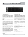 3
3
-
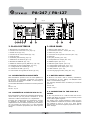 4
4
-
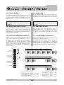 5
5
-
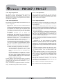 6
6
-
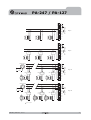 7
7
-
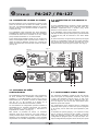 8
8
-
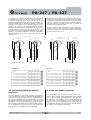 9
9
-
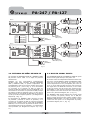 10
10
-
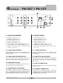 11
11
-
 12
12
-
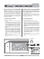 13
13
-
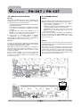 14
14
-
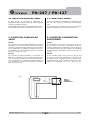 15
15
-
 16
16
-
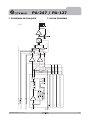 17
17
-
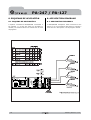 18
18
-
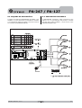 19
19
-
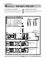 20
20
-
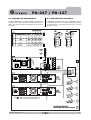 21
21
-
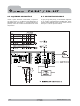 22
22
-
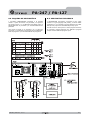 23
23
-
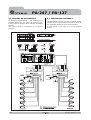 24
24
-
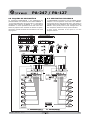 25
25
-
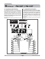 26
26
-
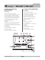 27
27
-
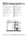 28
28
-
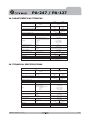 29
29
-
 30
30
-
 31
31
-
 32
32


Optimus PA-127 Manual de usuario
- Categoría
- Amplificadores de audio
- Tipo
- Manual de usuario
- Este manual también es adecuado para
en otros idiomas
- English: Optimus PA-127 User manual
Artículos relacionados
-
Optimus UP-120M4 Ficha de datos
-
-
-
-
-
-
-
-
-