
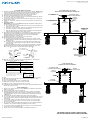
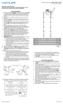
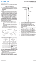
LOOP/CHAIN LINK/LOOP MOUNT
1) Pass wire from fixture through stem and screw stem to top of fixture. NOTE: Thread
locking compound must be applied to all stem threads as noted with symbol (3)
to prevent accidental rotation of fixture during cleaning, relamping, etc.
2) Pass fixture wire through remaining stems and screw stems together.
3) Thread one small threaded pipe into end of each small loop.
4) On each side of fixture, pass fixture wire from last stem through first loop. Thread
each first loop onto end of each last stem.
5) On each side of fixture, pass fixture wire through each small loop on canopy and
through hole in canopy.
6) Attach one chain link to small loop at end of each stem and to each small oop on
canopy.
7) TURN OFF POWER.
IMPORTANT: Before you start, NEVER attempt any work without shutting off the
electricity until the work is done.
a) Go to the main fuse, or circuit breaker, box in your home. Place the main power
switch in the “OFF” position.
b) Unscrew the fuse(s), or switch “OFF” the circuit breaker switch(s), that control
the power to the fixture or room that you are working on.
c) Place the wall switch in the “OFF” position. If the fixture to be replaced has a
switch or pull chain, place those in the “OFF” position.
8) Thread hexnut onto threaded pipe so that 5 threads are exposed above hexnut.
Thread that end of the threaded pipe into mounting strap and tighten hexnut
against mounting strap. Screw second hexnut onto end of threaded pipe
protruding from back of mounting strap.
9) Attach mounting strap to outlet box. (Screws not provided.)
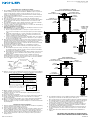
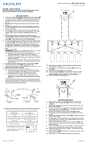
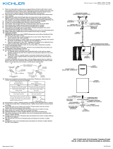
10) Grounding instructions: (See Illus. A or B).
A) On fixtures where mounting strap is provided with a hole and two raised
dimples. Wrap ground wire from outlet box around green ground screw, and
thread into hole.
B) On fixtures where a cupped washer is provided. Attach ground wire from
outlet box under cupped washer and green ground screw, and thread into
mounting strap.
If fixture is provided with ground wire. Connect fixture ground wire to outlet box
ground wire with wire connector. (Not provided.) After following the above steps.
Never connect ground wire to black or white power supply wires.
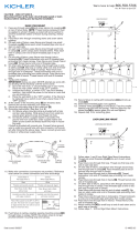
11) Make wire connections (connectors not provided.) Reference chart below for
correct connections and wire accordingly.
12) Push fixture to ceiling, carefully passing threaded pipe through hole in canopy.
13) Thread finial onto threaded pipe. Tighten finial to secure fixture to ceiling.
14) Insert recommended bulb.
15) Slip one small rubber washer onto each thumbscrew.
16) Raise glass up to fixture. Pass hole in glass over bulb.
17) Align holes in side of glass with holes in ring on socket.
18) Carefully push end of thumbscrew into hole in glass and thread thumbscrew into
hole in side of ring on socket.
RIGID STEM MOUNT
1) Remove each small loop from the canopy. NOTE: The lockwashers and hexnuts
will be used in step 5.
2) Remove threaded pipe from each small loop.
3) Pass wire through stems and screw stems into each coupling on top of fixture
body. NOTE: Thread locking compound must be applied to all stem threads as
noted with symbol (3) to prevent accidental rotation of fixture during cleaning,
relamping, etc.
4) Pass fixture wire through remaining stems and screw stems together.
5) On each side of fixture, pass fixture wire through the small threaded pipe removed
from each small loop. Thread one small threaded pipe into end of last stem on each
side of fixture.
6) On each side of fixture, pass fixture wire through each hole in canopy. Lower
canopy down towards stems. Pass each hole in canopy over end of threaded
pipes on each last stem.
7) On each side of fixture, pass fixture wire through hole in one lockwasher. Thread one
lockwasher onto each threaded pipe protruding from inside canopy.
8) On each side of fixture, pass fixture wire through hole in one hexnut and thread
each hexnut onto end of threaded pipe.
9) Follow steps 10-18 in Loop/Chain Link/Loop Installation Instructions.
Connect Black or
Red Supply Wire to:
Connect
White Supply Wire to:
Black White
*Parallel cord (round & smooth) *Parallel cord (square & ridged)
Clear, Brown, Gold or Black
without tracer
Clear, Brown, Gold or Black
with tracer
Insulated wire (other than green)
with copper conductor
Insulated wire (other than green)
with silver conductor
*Note: When parallel wires (SPT I & SPT II)
are used. The neutral wire is square shaped
or ridged and the other wire will be round in
shape or smooth (see illus.) Neutral Wire
Date Issued: 12/11/15 IS-43059-US
GREEN GROUND
SCREW
CUPPED
WASHER
AB
OUTLET BOX
GROUND
FIXTURE
GROUND
DIMPLES
WIRE CONNECTOR
(NOT PROVIDED)
OUTLET BOX
GROUND
GREEN GROUND
SCREW
FIXTURE
GROUND
CANOPY
ESCUDETE
STEM
VÁSTAGO
HEXNUT
TUERCA HEXAGONAL
LOOP
ANILLO
CHAIN LINK
ESLABÓN DE CADENA
3
MOUNTING STRAP
PLANCHA PARA MONTAR
3
GLASS
VIDRIO
COUPLING
ACOPLAMIENTO
THUMBSCREW
TORNILLO DE
MARIPOSA
SMALL RUBBER WASHER
PEQUEÑA ARANDELA DE
CAUCHO
FINIAL
CAPUCHON
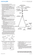
CANOPY
ESCUDETE
STEM
VÁSTAGO
HEXNUT
TUERCA HEXAGONAL
3
MOUNTING STRAP
PLANCHA PARA MONTAR
3
COUPLING
ACOPLAMIENTO
FINIAL
ORNEMENT
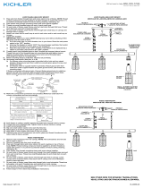
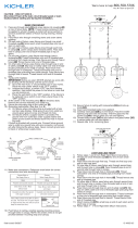
LOOP/CHAIN LINK/LOOP MOUNT
MONTAJE DE LAZO/ESLABÓN DE CADENA/LAZO
RIGID STEM MOUNT
MONTAJE DEL VÁSTAGO NERVADO
SEE OTHER SIDE FOR SPANISH TRANSLATIONS.
VEA EL OTRO LADO DE TRADUCCIONES AL ESPAÑOL.
We’re here to help 866-558-5706
Hrs: M-F 9am to 5pm EST
3
3
3
3
3

MONTAJE DE LAZO/ ESLABÓN DE CADENA
1) Pase el alambre del artefacto desde el cuerpo del artefacto a través del vástago y
atornille el vástago a la parte superior del artefacto. NOTA: El compuesto para rosca
estanca se debe aplicar a todas las roscas del vástago como se notó con el
símbolo (3) para impedir la rotación accidental del artefacto durante la limpieza,
instalación de una bombilla nueva, etc.
2) Pase el alambre del artefacto a través de los vástagos restantes y atornille juntos
todos los vástagos.
3) Enrosque un tubo roscado pequeño en el extremo de cada anillo pequeño.
4) De cada lado del artefacto, pase el alambre del artefacto desde el último vástago
a través del primer anillo. Enrosque cada primer anillo en el extremo de cada
último vástago.
5) De cada lado del artefacto, pase el alambre del artefacto a través de cada anillo
pequeño en el escudete y a través del agujero en el escudete.
6) Conecte un eslabón de cadena al anillo pequeño en el extremo de cada vástago y
a cada anillo pequeño en el escudete.
7) APAGUE LA ALIMENTACIÓN ELÉCTRICA.
IMPORTANTE: Antes de comenzar, NUNCA trate de trabajar sin antes desconectar
la corriente hasta que el trabajo se termine.
a) Vaya a la caja principal de fusibles, o interruptor o caja de circuitos de su
casa. Coloque el interruptor de la corriente principal en posición de apagado
“OFF”.
b) Desatornille el (los) fusible (s), o coloque el interruptor o interruptores del
breaker en posición de apagado “OFF”, que controla (n) la corriente hacia el
artefacto o habitación donde está trabajando.
c) Coloque el interruptor de pared en posición de apagado “OFF”. Si el artefacto
que se va a reemplazar tiene un interruptor o cadena que se jala, colóquelos
en la posición de apagado “OFF”.
8) Enrosque la tuerca hexagonal en el tubo roscado de tal forma que 5 roscas esté
expuestas sobre la tuerca hexagonal. Enrosque ese extremo del tubo roscado en la
barra de montaje y apriete la tuerca hexagonal contra la barra de montaje.
Atornille la segunda tuerca hexagonal en el extremo del tubo roscado que sobresale
de atrás de la abrazadera de montaje.
9) Una la barra de montaje a la caja de salida. (no se suministran los tornillos).
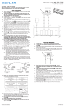
10) Instrucciones de conexión a tierra solamente para los Estados Unidos. (Vea la
ilustracion A o B).
A) En las lámparas que tienen el fleje, de montaje con un agujero y dos hoyue
los realzados. Enrollar el alambre a tierra de la caja tomacorriente alrededor
del tornillo verde y pasarlo por el aquiero.
B) En las lámparas con una arandela acopada. Fijar el alambre a tierra de la caja
tomacorriente del ajo de la arandela acoada y tornillo verde, y paser por el
fleje de montaje.
Si la lámpara viene con alambre a tierra. Conecter el alambre a tierra de la
lámpara al alambre a tierra de la caja tomacorriente con un conector de alambres
(no incluido) espués de seguir los pasos anteriores. Nunca conectar el alambra a
tierra a los alambres eléctros negro o blanco.
11) Haga les conexiones de los alambres (no se proveen los connectores.) La tabla de
referencia de abajo indica las conexiones correctas y los alambres correspondientes.
12) Empuje el artefacto contra el techo, pasando cuidadosamente el tubo roscado
através del orificio en el escudete.
13) Atornille el capuchon en el tubo roscado. Ajuste el capuchon para asegurar el
artefacto en el techo.
14) Inserte la bombilla recomendada.
15) Deslice una pequeña arandela de caucho por encima de cada tornillo de mariposa.
16) Levante el vidrio hasta el artefacto. Pase el orificio ubicado en el vidrio por
encima de la bombilla.
17) Alinee los orificios laterales del vidrio con los orificios del anillo del portalámparas.
18) Empuje con cuidado el extremo del tornillo de mariposa dentro del orificio
ubicado en el vidrio y enrosque el tornillo de mariposa en el orificio lateral del anillo
del portalámparas.
MONTAJE DEL VÁSTAGO NERVADO
1) Remueva cada anillo pequeño del escudete. NOTA: Las arandelas de seguridad y
tuercas hexagonales serán usadas en el paso 5.
2) Remueva el tubo roscado de cada anillo pequeño.
3) Pase el alambre del artefacto a través del vástago y atornille el vástago al tope del
artefacto. NOTA: El compuesto para rosca estanca se debe aplicar a todas las
roscas del vástago como se notó con el símbolo (3) para impedir la rotación acci
dental del artefacto durante la limpieza, instalación de una bombilla nueva, etc.
4) Pase el alambre del artefacto a través de los vástagos restantes y atornille los
vástagos juntos.
5) De cada lado del artefacto, pase el alambre del artefacto a través del tubo roscado
pequeño que fue removido de cada anillo pequeño. Enrosque un
tubo roscado pequeño en el extremo del último vástago de cada lado del artefacto.
6) De cada lado del artefacto, pase el alambre del artefacto a través de cada agujero
en el escudete. Baje el escudete hacia los vástagos. Pase cada agujero en el
escudete sobre el extremo de los tubos roscados en cada último vástago.
7) De cado lado del artefacto, pase el alambre del artefacto a través del agujero en
una arandela de seguridad. Enrosque una arandela de seguridad en cada tubo
roscado que sobresale desde dentro del escudete.
8) De cada lado del escudete, pase el alambre del artefacto a través del agujero en
una tuerca hexagonal y enrosque cada tuerca hexagonal en el extremo del tubo
roscado.
9) Siga los pasos 10-18 en las Instrucciones de Instalación del Lazo/Eslabón de
Cadena.
Conectar el alambre de
suministro negro o rojo al
Conectar el alambre de
suministro blanco al
Negro Blanco
*Cordon paralelo (redondo y liso) *Cordon paralelo (cuadrado y estriado)
Claro, marrón, amarillio o negro
sin hebra identificadora
Claro, marrón, amarillio o negro
con hebra identificadora
Alambre aislado (diferente del verde)
con conductor de cobre
Alambre aislado (diferente del
verde) con conductor de plata
*Nota: Cuando se utiliza alambre paralelo
(SPT I y SPT II). El alambre neutro es de forma
cuadrada o estriada y el otro alambre será de
forma redonda o lisa. (Vea la ilustracíón). Hilo Neutral
Date Issued: 12/11/15 IS-43059-US
ARANDELA
CONCAVA
AB
TIERRA DE LA
CAJA DE SALIDA
TORNILLO DE TIERRA,
VERDE
DEPRESIONES
TIERRA
ARTEFACTO
CONECTOR DE ALAMBRE
(NO SE PROVEE)
TIERRA DE LA
CAJA DE SALIDA
TORNILLO DE TIERRA,
VERDE
TIERRA
ARTEFACTO
SEE OTHER SIDE FOR ENGLISH TRANSLATIONS.
VEA EL OTRO LADO DE TRADUCCIONES AL INGLÉS.
We’re here to help 866-558-5706
Hrs: M-F 9am to 5pm EST
CANOPY
ESCUDETE
STEM
VÁSTAGO
HEXNUT
TUERCA HEXAGONAL
LOOP
ANILLO
CHAIN LINK
ESLABÓN DE CADENA
3
MOUNTING STRAP
PLANCHA PARA MONTAR
3
GLASS
VIDRIO
COUPLING
ACOPLAMIENTO
THUMBSCREW
TORNILLO DE
MARIPOSA
SMALL RUBBER WASHER
PEQUEÑA ARANDELA DE
CAUCHO
FINIAL
CAPUCHON
CANOPY
ESCUDETE
STEM
VÁSTAGO
HEXNUT
TUERCA HEXAGONAL
3
MOUNTING STRAP
PLANCHA PARA MONTAR
3
COUPLING
ACOPLAMIENTO
FINIAL
ORNEMENT
LOOP/CHAIN LINK/LOOP MOUNT
MONTAJE DE LAZO/ESLABÓN DE CADENA/LAZO
RIGID STEM MOUNT
MONTAJE DEL VÁSTAGO NERVADO
3
3
3
3
3
-
 1
1
-
 2
2


Kichler 43059CLP Instrucciones de operación
- Tipo
- Instrucciones de operación
- Este manual también es adecuado para
en otros idiomas
Otros documentos
-
 Kichler Lighting 43059CLP Manual de usuario
-
 Kichler Lighting 43995CH Manual de usuario
-
 Kichler Lighting 44077BK Manual de usuario
-
 Kichler Lighting 44081BK Manual de usuario
-
 Kichler Lighting 44205PN Manual de usuario
-
 Kichler Lighting 44082BK Manual de usuario
-
 Kichler Lighting 43755AUB Manual de usuario
-
 Kichler Lighting 49835AZ Manual de usuario
-
 Kichler Lighting 42474PN Manual de usuario
-
 Kichler Lighting 43348CLP Manual de usuario


