Kichler Lighting 43995CH Manual de usuario
- Tipo
- Manual de usuario

Date Issued: 09/28/17 IS-43995-US
We’re here to help 866-558-5706
Hrs: M-F 9am to 5pm EST
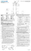
CAUTION – RISK OF SHOCK –
Disconnect Power at the main circuit breaker panel or main
fusebox before starting and during the installation.
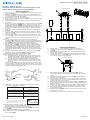
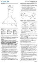
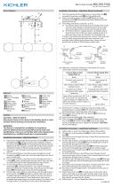
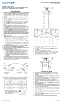
LOOP/LINK/LINK MOUNT
1) Follow steps 1 - 7 from Rigid Stem Mount Instructions.
2) Thread one small threaded pipe[7] into end of each small
loop[19].
3) Pass xture wire through rst loop. Thread one rst loop onto
end of each last stem.
4) On one side of xture, pass xture wire through second loop
and through hole in canopy[8]. Pass threaded pipe at end of
second loop through hole in canopy.
5) Pass xture wire through hole in lockwasher[9]. Thread
lockwasher onto end of threaded pipe protruding from inside
canopy.
6) Pass xture wire through hole in hexnut[10]. Thread hexnut
onto end of threaded pipe.
7) On other side of xture, pass xture wire through second loop
and through hole in canopy. Pass threaded pipe at end of sec-
ond loop through hole in canopy.
8) Pass xture wire through loop on end of safety cable[11]. Slip
loop on safety cable over end of threaded pipe protruding from
inside of canopy.
9) Pass xture wire through hole in lockwasher. Thread lockwash-
er onto end of threaded pipe protruding from inside canopy.
10) Pass xture wire through hole in hexnut. Thread hexnut onto
end of threaded pipe.
11) Attach locking link[20] to small loop at end of each stem and to
each loop on canopy.
12) Follow steps 12 - 20 from Rigid Stem Mount Instructions.
RIGID STEM MOUNT
1) Align a hole of a support arm [1] with a hole on a corner of the
lower frame [2].
2) Thread a nial [3] in from the bottom of the lower frame into
the hole. Tighten to secure the support arm to the frame. (The
arm should be ush with the frame).
3) Repeat steps 1-2 for the remaining arms.
4) Align the holes of the upper frame [4] with the holes on the top
of the support arms.
5) Thread the nials into the holes to secure the upper frame to
the arms.
6) Pass wire through stems[5] and screw stems into couplings[6]
on top of xture body. NOTE: 12.00” (Minimum) Stems are
required for mounting. NOTE: Thread locking compound must
be applied to all stem threads as noted with arrow symbol to
prevent accidental rotation of xture during cleaning, relamp-
ing, etc.
7) Pass xture wire through remaining stems and screw stems
together.
8) On each side of xture, pass xture wire through one small
threaded pipe[7]. Screw each small threaded pipe onto top of
stem on each side.
9) On each side of xture, pass xture wires through each hole
in canopy[8]. Lower canopy down towards stems. Pass each
hole in canopy over end of each threaded pipe on top of
stems.
10) On one side of xture, pass xture wire through hole in
lockwasher[9]. Thread lockwasher onto end of threaded pipe
protruding from inside canopy. Pass xture wire through hole in
hexnut[10]. Thread hexnut onto end of threaded pipe.
11) On other side of xture, pass xture wire through loop on
end of safety cable[11]. Slip loop on safety cable over end of
threaded pipe protruding from inside of canopy. Pass xture
wire through hole in lockwasher. Thread lockwasher onto end
of threaded pipe protruding from inside canopy. Pass xture
wire through hole in hexnut. Thread hexnut onto end of thread-
ed pipe.
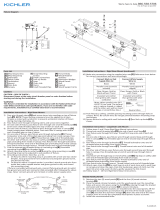
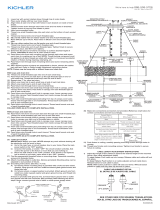
12) Find the appropriate threaded holes on mounting strap[12].
Assemble mounting screws [13] into threaded holes
13) Attach mounting strap to the outlet box [14].
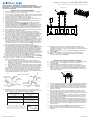
14) Grounding instructions: (See Illus. A or B).
A) On xtures where mounting strap is provided with a hole
and two raise dimples. Wrap ground wire from outlet box
around green ground screw, and thread into hole.
B) On xtures where a cupped washer is provided. Put
ground wire from outlet box under cupped washer and
green ground screw and thread screw into hole in mount-
ing strap.
If xture is provided with ground wire. Connect xture ground
wire to outlet box ground wire with wire connector, (not provid-
ed) after following the above steps. Never connect ground wire
to black or white power supply wires.
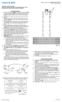
15) Make wire connections. Reference chart below for correct
connections and wire accordingly.
16) Push xture to ceiling, carefully passing mounting screws
through holes in canopy. NOTE: Be certain wires do not get
pinched between mounting strap and canopy.
17) Secure xture to ceiling with lockwashers[15] and lock-up
knobs[16].
18) Insert recommended bulbs (not supplied).
19) Carefully lower glass shade[17] over the bulb and onto the
glass holder [18].
GREEN GROUND
SCREW
CUPPED
WASHER
OUTLET BOX
GROUND
FIXTURE
GROUND
DIMPLES
WIRE CONNECTOR
OUTLET BOX
GROUND
GREEN GROUND
SCREW
FIXTURE
GROUND
A
B
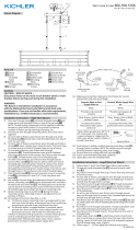
Connect Black or
Red Supply Wire to:
Connect
White Supply Wire to:
Black White
*Parallel cord (round & smooth) *Parallel cord (square & ridged)
Clear, Brown, Gold or Black
without tracer
Clear, Brown, Gold or Black
with tracer
Insulated wire (other than green)
with copper conductor
Insulated wire (other than green)
with silver conductor
*Note: When parallel wires (SPT I & SPT II)
are used. The neutral wire is square shaped
or ridged and the other wire will be round in
shape or smooth (see illus.)
Neutral Wire
►
►
►
►
►
►
►
►
1
2
3
4
5
6
8
►
► ►
►
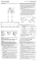
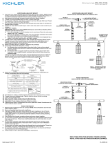
LOOP/LINK/LOOP MOUNT
RIGID STEM MOUNT
7
11
9
10
12
13
14
15
16
17
18
7
19
8
9
10
12
13
14
11
20
►
►
►
►
►
►
►
►
1
2
3
4
5
6
8
►
► ►
►
LOOP/LINK/LOOP MOUNT
RIGID STEM MOUNT
7
11
9
10
12
13
14
15
16
17
18
7
19
8
9
10
12
13
14
11
20
►
►
►
►
►
►
►
►
1
2
3
4
5
6
8
►
► ►
►
LOOP/LINK/LOOP MOUNT
RIGID STEM MOUNT
7
11
9
10
12
13
14
15
16
17
18
7
19
8
9
10
12
13
14
11
20

Date Issued: 09/28/17 IS-43995-US
Estamos aquí para ayudarle 866-558-5706
Horario: Lunes-Viernes 9am a 5pm EST (hora ocial del este)
16) Empujelajaciónaltecho,pasandocuidadosamentelos
tornillosdemontajeatravésdeagujeroseneldosel.NOTA:
Asegúresedequeloscablesnosepellizquenentrelacorreade
montajeyeldosel.
17) Fijarlajaciónaltechoconloslatiguillos[15]ylasperillasde
bloqueo[16].
18) Insertelasbombillasrecomendadas(nosuministradas).
19) Bajeconcuidadolacortinadevidrio[17]sobreelbulboy
sobreelsoportedecristal[18].
MONTAJE DE LAZO/ ESLABÓN DE CADENA
1) Sigalospasos1al7delasInstruccionesdemontajedelvástago.
2) Atornilleeltuboroscado[7]enelextremodecadalazo
pequeño[19].
3) Paseelalambredelartefactoatravésdelprimerlazo
pequeño.Fijeellazopequeñoalextremodelúltimovástago.
4) Paseelcableporunladodelartefactoatravésdelsegundo
anilloyluegoporeloriciodelescudete[8].Paseeltuboros-
cadoqueestáconectadoalextremodelsegundoanilloporel
oriciodelescudete.
5) Paseelalambredelartefactoatravésdelagujeroenlaarande-
ladeseguridad[9].Rosquelaarandeladeseguridaddentrodel
extremodeltuboroscadoquesobresaledelescudeteinterior.
6) Paseelalambredelartefactoatravésdelagujeroenlatuerca
hexagonal[10].Rosquelatuercahexagonalsobreelextremo
deltuboroscado.
7) Paseelcableporelotroladodelartefactoatravésdelse-
gundoanilloyluegoporeloriciodelescudete.Paseeltubo
roscadoqueestáconectadoalextremodelsegundoanillopor
eloriciodelescudete.
8) Paseelcabledelartefactoporelanillosituadoenelextremo
delcabledeseguridad[11].Corraelanillodelcabledesegu-
ridadsobreelextremodeltuboroscadoquesobresaledela
carainteriordelescudete.
9) Paseelalambredelartefactoatravésdelagujeroenlaaran-
deladeseguridad.Rosquelaarandeladeseguridaddentrodel
extremodeltuboroscadoquesobresaledelescudeteinterior.
10) Paseelalambredelartefactoatravésdelagujeroenlatuerca
hexagonal.Rosquelatuercahexagonalsobreelextremodel
tuboroscado.
11) Fijeeleslabóndebloqueo[20]aunpequeñolazoenelex-
tremodecadavástagoyacadabucleeneldosel.
12) Sigalospasos12al20delasInstruccionesdemontajedel
vástago.
MONTAJE DEL VÁSTAGO NERVADO
1) Alineeunagujerodeunbrazodesoporte[1]conunagujero
enunaesquinadelmarcoinferior[2].
2) Enrosqueunapunta[3]desdelaparteinferiordelmarcoinferi-
oreneloricio.Aprieteparajarelbrazodesoportealmarco.
(Elbrazodebeestaralineadoconelmarco).
3) Repitalospasos1-2paralosbrazosrestantes.
4) Alineelosoriciosdelmarcosuperior[4]conlosagujerosen
lapartesuperiordelosbrazosdesoporte.
5) Enrosquelaspuntasenlosoriciosparaasegurarelmarco
superioralosbrazos.
6) Paseelalambredelartefactoatravésdelvástagoyatornilleel
vástagoaltopedelartefacto[5][6] NOTA:Serequieren12.00
“(mínimo)tallosparaelmontaje. NOTA:Elcompuestopararosca
estancasedebeaplicaratodaslasroscasdelvástagocomose
notóconelsímbolo(3)paraimpedirlarotaciónaccidentaldelarte-
factodurantelalimpieza,instalacióndeunabombillanueva,etc.
7) Paseelalambredelartefactoatravésdelosvástagosrestan-
tesyatornillelosvástagosjuntos.
8) Encadaladodelartefacto,paseelalambredelartefactoa
travésdeuntuboroscadopequeño[7].Enrosquecadatubo
roscadopequeñoenlapartesuperiordelvástagoencadalado.
9) Encadaladodelartefacto,paselosalambresdelartefactoa
travésdecadaagujeroenelescudete[8].Bajeelescudete
hacialosvástagos.Pasecadaagujeroenelescudetesobreel
extremodecadatuboroscadoarribadelosvástagos.
10) Enunladodelartefacto,paseelalambredelartefactoatravés
delagujeroenlaarandeladeseguridad[9].Enrosquelaaran-
deladeseguridadenelextremodeltuboroscadoquesobre-
saledesdedentrodelescudete.Paseelalambredelartefacto
atravésdelagujeroenlatuercahexagonal[10].Enrosquela
tuercahexagonalenelextremodeltuboroscado.
11) Enelotroladodelartefacto,paseelalambredelartefactoa
travésdelanilloenelextremodelcabledeseguridad[11].Deslice
elanilloenelcabledeseguridadsobreelextremodeltuboros-
cadoquesobresaledesdedentrodelescudete.Paseelalambre
delartefactoatravésdelagujeroenlaarandeladeseguridad.
Enrosquelaarandeladeseguridadenelextremodeltuborosca-
doquesobresaledesdedentrodelescudete.Paseelalambredel
artefactoatravésdelagujeroenlatuercahexagonal.Enrosque
latuercahexagonalenelextremodeltuboroscado.
12) Enelcentrodelacorreademontaje[12]estánlasranurasde
cierre.Retireelconjuntoquecoincidaconsucajadesalida[13].
13) Fijelacorreademontajealacajadesalida[14].
14) InstruccionesdeconexiónatierrasolamenteparalosEstados
Unidos.(VealailustracionAoB).
A) Enlaslámparasquetieneneleje,demontajeconun
agujeroydoshoyuelosrealzados.Enrollarelalambrea
tierradelacajatomacorrientealrededordeltornilloverde
ypasarloporelaquiero.
B) Enlaslámparasconunaarandelaacopada.Fijarelalam-
breatierradelacajatomacorrientedelajodelaarandela
acoadaytornilloverde,ypaserporelejedemontaje.
Silalámparavieneconalambreatierra.Conecterelalambre
atierradelalámparaalalambreatierradelacajatomacor-
rienteconunconectordealambres(noincluido)espuésde
seguirlospasosanteriores.Nuncaconectarelalambraatierra
alosalambreseléctrosnegrooblanco.
15) Hagalesconexionesdelosalambres(noseproveenlos
connectores.)Latabladereferenciadeabajoindicalasconex-
ionescorrectasylosalambrescorrespondientes.
ARANDELA
CONCAVA
TIERRA DE LA
CAJA DE SALIDA
TORNILLO DE TIERRA,
VERDE
DEPRESIONES
TIERRA
ARTEFACTO
CONECTOR DE ALAMBRE
TIERRA DE LA
CAJA DE SALIDA
TORNILLO DE TIERRA,
VERDE
TIERRA
ARTEFACTO
A
B
Conectar el alambre de
suministro negro o rojo al
Conectar el alambre de
suministro blanco al
Negro Blanco
*Cordon paralelo (redondo y liso)
*Cordon paralelo (cuadrado y estriado)
Claro, marrón, amarillio o negro
sin hebra identificadora
Claro, marrón, amarillio o negro
con hebra identificadora
Alambre aislado (diferente del verde)
con conductor de cobre
Alambre aislado (diferente del
verde) con conductor de plata
*Nota: Cuando se utiliza alambre paralelo
(SPT I y SPT II). El alambre neutro es de forma
cuadrada o estriada y el otro alambre será de
forma redonda o lisa. (Vea la ilustracíón).
Hilo Neutral
PRECAUCIÓN – RIESGO DE DESCARGA ELÉCTRICA –
Desconecte la electricidad en el panel principal del interruptor
automático o caja principal de fusibles antes de comenzar y
durante la instalación.
►
►
►
►
►
►
►
►
1
2
3
4
5
6
8
►
► ►
►
LOOP/LINK/LOOP MOUNT
RIGID STEM MOUNT
7
11
9
10
12
13
14
15
16
17
18
7
19
8
9
10
12
13
14
11
20
►
►
►
►
►
►
►
►
1
2
3
4
5
6
8
►
► ►
►
LOOP/LINK/LOOP MOUNT
RIGID STEM MOUNT
7
11
9
10
12
13
14
15
16
17
18
7
19
8
9
10
12
13
14
11
20
►
►
►
►
►
►
►
►
1
2
3
4
5
6
8
►
► ►
►
LOOP/LINK/LOOP MOUNT
RIGID STEM MOUNT
7
11
9
10
12
13
14
15
16
17
18
7
19
8
9
10
12
13
14
11
20
-
 1
1
-
 2
2


Kichler Lighting 43995CH Manual de usuario
- Tipo
- Manual de usuario
en otros idiomas
- English: Kichler Lighting 43995CH User manual
Artículos relacionados
-
 Kichler Lighting 44077BK Manual de usuario
-
 Kichler Lighting 44043AUB Manual de usuario
-
 Kichler Lighting 44285WWW Manual de usuario
-
 Kichler Lighting 44296WWW Manual de usuario
-
 Kichler Lighting 44180BKT Manual de usuario
-
 Kichler Lighting 44250NI Manual de usuario
-
 Kichler Lighting 44038NI Manual de usuario
-
 Kichler Lighting 43348CLP Manual de usuario
-
 Kichler Lighting 44081BK Manual de usuario
-
 Kichler Lighting 43059CLP Manual de usuario


