Cadet Manufacturing 14910 Guía de instalación
- Categoría
- Calentadores espaciales
- Tipo
- Guía de instalación

BTF Series Thermostat
WARNING
Turn the electrical power off at the electrical panel board (circuit breaker or fuse box) and lock or tag
the panel board door to prevent someone from turning on power while you are working on the heater.
Failure to do so could result in serious electrical shock, burns, or possible death.
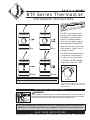
CONTROLS
Turn knob counter-clockwise for cooler room
temperature. Turn knob clockwise for warmer
room temperature.
If you are uncomfortable working with electrical appliances, unable to follow these
guidelines, or do not have the necessary equipment; consult a licensed electrician.
Installation Instructions
www.cadetco.com Tel: 360-693-2505 P.O. Box 1675 Vancouver, WA 98668-1675
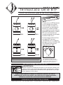
IMPORTANT INSTRUCTIONS
The BTF series heater mount
thermostat for Cadet electric
baseboards can be used to
control a baseboard heater
at the unit. Designed to replace
the detachable baseboard end
plate, the BTF easily installs onto
either end of a Cadet F-series
baseboard heater.
The BTF line voltage thermostat
is capable of switching up to
17 amps, of a resistive load,
at 120, 208 or 240 VAC. Setpoint
temperature range: 45º - 80ºF.
C
o
o
l
e
r
W
a
r
m
e
r
LO
HI
OFF
HI
BTF1 BTF2
SAVE THESE INSTRUCTIONS
TOOLS REQUIRED
•
Phillips Screwdriver
•
Wire Connectors
•
Straight Screwdriver
BTF1TP BTF2TP
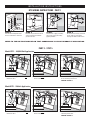
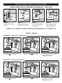
Set Position

STEP 1
Turn the electrical power off at
the circuit breaker or fuse box.
STEP 2
Remove the junction box cover
at the end of the baseboard
you wish to wire.
STEP 4
Disconnect one factory connector
on the side you have open,
leaving two loose heater wires.
REFER TO THE INSTRUCTIONS BELOW THAT CORRESPOND TO YOUR THERMOSTAT APPLICATION.
PART 2 - STEP 5
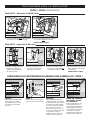
BTF WIRING INSTRUCTIONS - PART 1
Model BTF1 - 120 Volt Application
A. Connect the hot supply wire to the red
thermostat wire.
B. Connect the black
thermostat wire to one
of the heater wires.
C. Connect the neutral supply wire to the
remaining heater wire.
PROCEED TO PART 3
A. Connect a hot supply wire to the red
thermostat wire.
Model BTF1 – 240/208 Volt Application
B. Connect the black thermostat wire to one
of the heater wires.
C. Connect the remaining hot supply wire
to the remaining heater wire.
PROCEED TO PART 3
INSTALLATION INSTRUCTIONS
STEP 3
Connect the supply grounding
wire to the green grounding
pigtail provided.

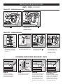
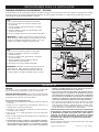
PART 2 - STEP 5 (CONTINUED)
BTF WIRING INSTRUCTIONS CONCLUSION - PART 3
STEP 6
Carefully tuck all wires
into wiring compartment
and attach the thermostat
to the baseboard heater.
STEP 7
Turn the power back on at the
circuit breaker or fuse box.
STEP 8A
Turn the thermostat knob fully
clockwise. When the room
reaches comfort level, turn
the knob counterclockwise
until a slight click is heard.
The heater will now cycle
around this preset temperature.
INSTALLATION INSTRUCTIONS
A. Connect the red thermostat
wire labeled L2 to the black
thermostat wire labeled OFF
as shown.
Model BTF2 – 120 Volt Application
B. Connect the neutral supply
wire to one of the heater wires.
C. Connect the supply hot
wire to the remaining
red
thermostat wire.
D. Connect the remaining
black thermostat wire to
the remaining heater wire.
PROCEED TO PART 3
RED
STEP 8B - Tamper
Proof Models
Remove plastic plug and adjust
the thermostat shaft to desired
setting using a screwdriver.
Replace the plastic plug. The
heater will now cycle around
this preset temperature.
Model BTF2 – 240/208 Volt Application
A. Connect the black thermostat wires to the
loose heater wires.
B. Connect the hot supply wires to the red
thermostat wires.
PROCEED TO PART 3

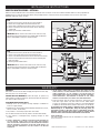
BTF2
1. Disconnect one factory connector on each baseboard.
2. Connect one supply wire to each red thermostat wire.
3. Connect one black thermostat wire to one wire from each heater.
4. Connect remaining black thermostat wire to the remaining wire
from each heater.
5. Connect ground to both heaters.
IMPORTANT: Wires shown in illustration are for reference only.
All electrical work and materials must comply with the National
Electric Code (NEC) and all state and local codes.
BTF1
1. Disconnect one factory connector on each baseboard.
2. Connect one supply lead to the red thermostat wire.
3. Connect black thermostat wire to one wire on each heater.
4. Connect remaining wire from each heater to the remaining
supply lead.
5. Connect ground wire to both heaters.
IMPORTANT: Wires shown in illustration are for reference only.
All electrical work and materials must comply with the National
Electric Code (NEC) and all state and local codes.
More than one baseboard heater can be wired in parallel on same circuit (be sure to check national and local codes for safety requirements).
Additional wire is required. Important: When wiring multiple heaters to one thermostat, the baseboards must be in the same room.
Maximum amperage rating: 17 amps.
MULTIPLE HEATER WIRING - OPTIONAL
©2009 Cadet Manufacturing Co. Printed in U.S.A. 03/10 #720107
INSTALLATION INSTRUCTIONS
WARR ANTY
WARRANTY
Warranties are non transferable and apply to original consumer only.
Warranty terms are set out below.
LIMITED ONE-YEAR WARRANTY: Cadet will repair or replace any
Cadet product, including thermostats, found to be defective within one
year after the date of purchase.
THESE WARRANTIES DO NOT APPLY:
1. Damage occurs to the product through improper installation or
incorrect supply voltage;
2. Damage occurs to the product through improper maintenance, misuse,
abuse, accident, or alteration;
3. The product is serviced by anyone other than Cadet.
4. If the date of manufacture of the product cannot be determined;
5. If the product is damaged during shipping through no fault
of Cadet.
6. CADET’S WARRANTY IS LIMITED TO REPAIR OR REPLACEMENT AS
SET OUT HEREIN. CADET SHALL NOT BE LIABLE FOR DAMAGES
SUCH AS PROPERTY DAMAGE OR FOR CONSEQUENTIAL DAMAGES
AND/OR INCIDENTAL EXPENSES RESULTING FROM BREACH OF
THESE WRITTEN WARRANTIES OR ANY EXPRESS OR IMPLIED
WARRANTY.
7. IN THE EVENT CADET ELECTS TO REPLACE ANY PART OF YOUR
CADET PRODUCT, THE REPLACEMENT PARTS ARE SUBJECT TO THE
SAME WARRANTIES AS THE PRODUCT. THE INSTALLATION OF
REPLACEMENT PARTS DOES NOT MODIFY OR EXTEND THE UNDER-
LYING WARRANTIES. REPLACEMENT OR REPAIR OF ANY CADET
PRODUCT OR PART DOES NOT CREATE ANY NEW WARRANTIES.
8. These warranties give you specific legal rights, and you may also
have other rights which vary from state to state. Cadet neither
assumes, nor authorizes anyone to assume for it, any other obligation
or liability in connection with its products other than as set out herein.
If you believe your Cadet product is defective, please, contact Cadet
Manufacturing Co. at 360-693-2505, during the warranty period, for
instructions on how to have the repair or replacement processed.
Warranty claims made after the warranty period has expired will be
denied. Products returned without authorization will be refused.
Parts and Service
Visit http://support.cadetco.com for information on where to obtain
parts and service.

Termostato serie BTF
ADVERTENCIA
Desconecte la electricidad en el tablero del panel eléctrico (caja de cortacircuitos o fusibles) y trabe
o coloque un cartel en la puerta del tablero del panel para evitar que alguien vuelva a conectar la
energía mientras se esté trabajando en el calentador. De lo contrario podrían producirse graves golpes
eléctricos, quemaduras e incluso la muerte.
Si no se siente cómodo al trabajar con artefactos eléctricos, no está en
condiciones de acatar estas pautas o no cuenta con los equipos necesarios,
solicite los servicios de un técnico electricista calificado.
Instrucciones para la instalación
www.cadetco.com Tel: 360-693-2505 P.O. Box 1675 Vancouver, WA 98668-1675
INSTRUCCIONES IMPORTANTES
CONSERVE ESTAS INSTRUCCIONES
CONTROLES
Gire la perilla en sentido contrario
a las manecillas del reloj para reducir
la temperatura ambiente. Gírela en el
sentido opuesto para aumentarla.
El termostato serie BTF de montaje
en el calentador para zócalos
eléctricos Cadet se puede usar
para controlar un calentador de
zócalo en la unidad. Diseñado
para reemplazar la placa extrema
desprendible del zócalo, el modelo
BTF se instala fácilmente en
cualquier extremo de un calentador
de zócalo Cadet serie F.
El termostato de voltaje de línea
del modelo BTF tiene una
capacidad de hasta 17 amperios,
de carga resistiva, a 120, 208 ó 240
VCA. Margen de fijación de
temperatura: 45º - 80ºF.
M
e
n
o
s
c
a
l
o
r
M
á
s
c
a
l
o
r
LO
HI
OFF
HI
BTF1 BTF2
HERRAMIENTAS NECESARIAS
•
Destornillador Phillips
•
Conectores de alambres
•
Destornillador plano
BTF1TP BTF2TP
Fijar posición

PASO 1
Desconecte la electricidad
en el cortacircuito o en la caja
de fusibles.
PASO 2
Retire la cubierta de la caja
de empalmes en el extremo
del zócalo que desea cablear.
PASO 4
Desenchufe un conector de
fábrica en el lado que esté
abierto, dejando sueltos dos
alambres del calentador.
CONSULTE LAS SIGUIENTES INSTRUCCIONES QUE CORRESPONDAN A SU TERMOSTATO.
PARTE 2 - PASO 5
INSTRUCCIONES PARA EL CABLEADO DEL MODELO BTF - PARTE UNO
Modelo BTF1 - Aplicación de 120 voltios
A. Conecte el cable activo de suministro
al alambre rojo
del termostato.
B. Conecte el alambre negro
del termostato
a uno de los alambres del calentador.
C. Conecte el cable neutro de suministro
al otro alambre del calentador.
PROSIGA CON LA 3ª PARTE
A. Conecte un alambre de suministro activo
al alambre rojo
del termostato.
Modelo BTF1 – Aplicación de 240/208 voltios
B. Conecte el alambre negro del termostato
a uno de los alambres del calentador.
C. Conecte el alambre de suministro activo
restante al otro alambre del calentador.
PROSIGA CON LA 3ª PARTE
INSTRUCCIONES PARA LA INSTALACIÓN
PASO 3
Conecte el alambre de puesta
a tierra del suministro al cable
en espiral verde de tierra
proporcionado.

PARTE 2 - PASO 5 (CONTINUACIÓN)
CONCLUSIÓN DE LAS INSTRUCCIONES DE CABLEADO PARA EL MODELO BTF - PARTE 3
PASO 6
Pliegue cuidadosamente todos
los alambres en el interior
del compartimiento y conecte
el termostato al calentador
de zócalo.
PASO 7
Vuelva a conectar la energía en
el cortacircuito o caja de fusibles.
PASO 8A
Gire la perilla del termostato
completamente en el sentido de
las manecillas del reloj. Cuando
la temperatura ambiente llegue
a un nivel que le resulte cómodo,
gire la perilla en el sentido
contrario hasta que se escuche
un ligero chasquido. El calentador
se encenderá y apagará
automáticamente según esta
temperatura preestablecida.
INSTRUCCIONES PARA LA INSTALACIÓN
A. Conecte el alambre rojo del
termostato rotulado L2 al
alambre negro rotulado OFF,
tal como se aprecia.
Modelo BTF2 – Aplicación de 120 voltios
B. Conecte el alambre neutro
de suministro a uno de los
alambres del calentador.
C. Conecte el alambre activo
de suministro al alambre rojo
restante del termostato.
D. Conecte el alambre de suministro
negro restante al otro alambre
del calentador.
PROSIGA CON LA 3ª PARTE
PASO 8B - Modelos
protegidos contra
uso indebido
Retire el tapón plástico y fije
el eje del termostato en el
ajuste que desee utilizando un
destornillador. Vuelva a poner
el tapón plástico. El calentador
se encenderá y apagará
automáticamente según esta
temperatura preestablecida.
Modelo BTF2 – Aplicación de 240/208 voltios
A. Conecte los alambres negros del termostato
a los alambres sueltos del calentador.
B. Conecte los cables activos de suministro
a los alambres rojos
del termostato.
PROSIGA CON LA 3ª PARTE

BTF2
1. Desenchufe un conector de fábrica en cada zócalo.
2. Conecte un alambre de suministro a cada alambre
rojo del termostato.
3. Conecte un alambre negro del termostato a un alambre
en cada calentador.
4. Conecte el alambre negro restante del termostato
al otro alambre en cada calentador.
5. Conecte la puesta a tierra en ambos calentadores.
IMPORTANTE: Los alambres que aparecen en la ilustración son
sólo de referencia. Todas las labores y materiales eléctricos
deben cumplir con el Código Nacional Eléctrico (“NEC”, por
su sigla en inglés) y con todos los códigos estatales y locales.
BTF1
1. Desenchufe un conector de fábrica en cada zócalo.
2. Conecte un conductor de suministro al alambre rojo
del termostato.
3. Conecte el alambre negro del termostato a un alambre
en cada calentador.
4. Conecte el alambre restante de cada calentador al otro
conductor de suministro.
5. Conecte el alambre de puesta a tierra a ambos calentadores.
IMPORTANTE: Los alambres que aparecen en la ilustración son
sólo de referencia. Todas las labores y materiales eléctricos deben
cumplir con el Código Nacional Eléctrico (“NEC”, por su sigla
en inglés) y con todos los códigos estatales y locales.
Es posible cablear más de un calentador de zócalo en paralelo en el mismo circuito (cerciórese de revisar los requisitos de seguridad en los códigos
nacionales y locales). Se requiere alambre adicional. Importante: Al cablear múltiples calentadores a un termostato, los zócalos deben estar en la
misma habitación. Amperaje nominal máximo: 17 amperios.
CABLEADO DE MÚLTIPLES CALENTADORES - OPCIONAL
©2009 Cadet Manufacturing Co. Printed in U.S.A. 03/10 #720107
INSTRUCCIONES PARA LA INSTALACIÓN
GAR ANTIA
GARANTIA
Las garantías no son transferibles y rigen sólo para el comprador
original. Los términos de la garantía se indican a continuación.
GARANTÍA LIMITADA DE UN AÑO: Cadet reparará o reemplazará todo
producto Cadet, incluyendo los termostatos, que presente averías en
un plazo de un año a partir de la fecha de compra.
Estas garantías no son pertinentes para:
1. Daños que sufra el producto por instalación o voltaje de suministro
incorrectos;
2. Daños que sufra el producto por mantenimiento incorrecto, uso
indebido, abuso, accidente o alteraciones;
3. Servicio que se le haya dado al producto por parte de personas
o entidades ajenas a Cadet.
4. Casos en que no se pueda determinar la fecha de fabricación
del producto;
5. Casos en que el producto resulte dañado durante el embarque por
causas ajenas a Cadet.
6. LA GARANTÍA DE CADET SE LIMITA A LA REPARACIÓN O REEMPLA-
ZO, TAL COMO SE ESTABLECE EN ESTE DOCUMENTO. CADET NO SE
HARÁ RESPONSABLE POR DAÑOS A LA PROPIEDAD O DAÑOS
CONSECUENTES, COMO TAMPOCO POR GASTOS ACCIDENTALES
DEBIDO AL INCUMPLIMIENTO DE ESTAS GARANTÍAS ESCRITAS O
DE CUALQUIER GARANTÍA EXPRESA O IMPLÍCITA.
7. EN CASO DE QUE CADET DECIDA REEMPLAZAR ALGUNA PIEZA DEL
PRODUCTO CADET, LOS REPUESTOS SE REGIRÁN POR LAS MIS-
MAS GARANTÍAS DEL PRODUCTO. LA INSTALACIÓN O REEMPLAZO
DE LOS REPUESTOS NO MODIFICA NI PROLONGA LAS GARANTÍAS
VIGENTES. EL REEMPLAZO O REPARACIÓN DE TODO PRODUCTO O
PIEZA CADET NO ORIGINA NINGÚN TIPO DE NUEVA GARANTÍA.
8. Estas garantías le otorgan derechos legales específicos y es posible
que usted tenga otros derechos que varíen de un estado a otro.
Cadet no asume ni autoriza a nadie que lo haga en su nombre, ningu-
na otra obligación o responsabilidad en relación con sus productos
que no sean las que se establecen en este documento.
Si durante el período de garantía usted considera que su producto Cadet
presenta defectos, comuníquese con Cadet Manufacturing Co. llamando
al 360-693-2505 para obtener instrucciones sobre cómo tramitar la
reparación o el reemplazo del producto. Los reclamos de garantía
presentados después de la finalización del período no serán acogidos.
Los productos que se devuelvan sin autorización serán rechazados.
Repuestos y servicio
En http://support.cadetco.com encontrará información sobre dónde
obtener repuestos y servicio.
-
 1
1
-
 2
2
-
 3
3
-
 4
4
-
 5
5
-
 6
6
-
 7
7
-
 8
8


Cadet Manufacturing 14910 Guía de instalación
- Categoría
- Calentadores espaciales
- Tipo
- Guía de instalación