
Owner's Manual
Manual del Propietario
®
THROUGH-THE-WALLAIRCONDITIONER
ACONDICIONADODEAIREA TRAVESDEPARED
ModeI, Modelo 580.72087200 580.72107200 580.72127200
Sears, Roebuck and Co., Hoffman Estates, IL 60179 U.S.A.
www.sears.com

TABLE OF CONTENTS ........................2
WARRANTY ..............................................2
SAFETY .....................................................3
ImportantSafety Instructions...................... 3
ELECTRICAL REQUIREMENTS .......4
INSTALLATION ........................................5
Installation Requirements ......................... 5
Installation ................................................ 6
Procedure A ............................................. 7
Procedure B ............................................. 9
Procedure C........................................... 11
OPERATION ...........................................12
How and Why ......................................... 12
Normal Sounds ...................................... 12
Capacity and Running Time ................... 12
Features ................................................. 13
Using the Air Conditioner ....................... 13
Air Conditioner Features ........................ 14
MAINTENANCE .....................................16
Air Filter Cleaning ................................... 16
Air Conditioner Cleaning ........................ 16
How to Remove the Front Grille ............. 16
How to Replace the Front Grille ............. 16
TROUBLESHOOTING .........................17
Before Calling for Service ...................... 17
ESPANOL ................................................18
MASTER PROTECTION
AGREEMENTS ......................................35
SERVICE NUMBERS ............ Back Cover
FULL ONE YEAR WARRANTY ON
THROUGH-THE-WALL AIR CONDITIONER
For one year from the date of purchase, when this
air conditioner is operated and maintained for
normal room cooling according to instructions in this
owner's manual, Sears will repair this air
conditioner, free of charge, if defective in material or
workmanship.
WARRANTY SERVICE IS AVAILABLE BY
CONTACTING SEARS SERVICE AT
1-800-4-MY-HOME ®.
This warranty applies only while this product is in
use in the United States.
This warranty gives you specific legal rights, and
you may also have other rights which vary from
state to state.
Sears, Roebuck and Co., D/817WA,
Hoffman Estates, IL 60179 U.S.A.
-2-

IMPORTANT SAFETY INSTRUCTIONS
The safety instructions below will tell you how to use your room air conditioner to avoid harm to yourself or
damage to your ROOM AIR CONDITIONER.
V!_W:_:t_II_[_FOR YOUR SAFETY
Do not store or use gasoline or other flammable
vapors and liquids in the vicinity of this or any other
appliance. Read product labels for flammability and
other warnings.
PREVENT ACCIDENTS
To reduce the risk of fire, electrical shock, or injury
to persons when using your air conditioner, follow
basic precautions, including the following:
• Be sure the electrical service is adequate for the
model you have chosen.
• If the air conditioner is to be installed in a window,
you will probably want to clean both sides of the
glass first. If the window is a triple-track type with a
screen panel included, you may want to remove
the screen completely before installation.
• Be sure the air conditioner has been securely and
correctly installed according to the instructions in
this manual.
Save this manual and installation instructions for
possible future use in removing or reinstalling this
unit.
• Use gloves when handling the air conditioner.
Be careful to avoid cuts from sharp metal fins on
front and rear coils.
V!_W,.1;i_ll_[dELECTRICAL INFORMATION
The complete electrical rating of your new room air
conditioner is stated on the serial plate. Refer to the
rating when checking the electrical requirements.
• Be sure the air conditioner is properly grounded.
To minimize shock and fire hazards, proper
grounding is important. The power cord is
equipped with a three-prong grounding plug for
protection against shock hazards.
• Your air conditioner must be plugged into a
properly grounded wall receptacle. If the wall
receptacle you intend to use is not adequately
grounded or protected by a time delay fuse or
circuit breaker, have a qualified electrician install
the proper receptacle.
• Do not run air conditioner with packing sheet of
the back of the sleeve, and packing corner and
blue tape of the air conditioner. This could result in
mechanical damage within the air conditioner.
• Do not use an extension cord or an adapter
plug.
_ Avoid fire hazard or electric shock.
Do not use an extension cord or an adapter plug.
Do not remove any prong from the power cord.
Grounding type
wall receptacle
Do not under any
circumstances cut,
remove, or bypass
the grounding prong
from this plug.
grounding plug
ENERGY SAVING IDEAS
• The capacity of the room air conditioner must fit
the room size for efficient and satisfactory
operation.
• install the room air conditioner on the shady side
of your home. A window that faces north is best
because it is shaded most of the day.
• Do not block air flow inside with blinds, curtains, or
furniture; or outside with shrubs, enclosures, or
other buildings.
• Close the floor and wall registers and the fireplace
damper so cool air does not escape up the
chimney and into the duct work.
• Keep blinds and drapes in other windows closed
during the sunniest part of the day.
• Clean the air filter as recommended in the
MAINTENANCE section of this manual.
• Proper insulation and weather stripping in your
home will help keep warm air out and cool air in.
• External house shading with trees, plants or
awnings will help reduce the air conditioner's work
load.
• Operate heat producing appliances such as
ranges, washers, dryers, and dishwashers during
the coolest part of the day.
-3-

OBSERVEALL LOCAL CODES AND
ORDINANCES.
DO NOT, UNDER ANY CIRCUMSTANCES,
REMOVE THE POWER SUPPLY CORD
GROUND PRONG.
ELECTRICAL GROUND IS REQUIRED ON
THIS APPLIANCE.
A 208/230-volt and 115-volt 60 Hz, AC only,
15A fused and properly grounded electrical
supply is required. A time delay fuse or time
delay circuit breaker is recommended. Use a
dedicated circuit, serving only this appliance.
DO NOT USE AN EXTENSION CORD.
RECOMMENDED GROUNDING METHOD
For your personal safety, this appliance must
be grounded. This appliance has a power
supply cord with a 3-prong grounding plug. To
minimize possible shock hazard, the cord must
be plugged into a mating grounding type wall
receptacle and grounded in accordance with
the National Electrical Code (ANSt/NFPA 70)
latest edition and all local codes and
ordinances. If a mating wall receptacle is not
available, it is the personal responsibility and
obligation of the customer to have a properly
grounded 3-prong wall receptacle installed by a
qualified electrician.
Electrical Shock Hazard
Plug into a grounded 3 prong outlet.
Do not remove ground prong.
Do not use an adapter.
Do not use an extension cord.
Failure to follow these instructions can result
in death, fire, or electrical shock.
Ground
prong I/! _ 'fl
/ 3-prong
_..k I \"--J I grounding
,J-prong _ I _ ] type wall
gg.rounalng k _'T'F I receptacle
Power_ "_
supply
cord
-4-

INSTALLATION REQUIREMENTS
If you use an existing wall sleeve, you should
measure its dimensions.
install the new air conditioner according to these
installation instructions to achieve the best
performance. All wall sleeves used to mount the
new air conditioner must be in good structural
condition and have a rear grille to securely attach
the new air conditioner. (FIG. 1)
With the Kenmore folding sleeve, you can
maintain the best performance of the new air
conditioner.
19-2//32"
(499 mrn)
(626 ram)
6mrn)
Air Conditioner
FIG. !
ELECTRICAL SERVICE
Check your available electrical service. The power
supply available must be the same as that shown
on the unit nameplate (found on left side of cabinet).
All models are equipped with a 3-prong service plug
to provide proper service and safe positive
grounding. Do not change plug in any way. Do not
use an adapter plug. If your present wall outlet does
not match your plug, call a qualified electrician to
make the necessary corrections. SAVE CARTON
for storage and this OWNER'S MANUAL for future
reference. The carton is the best way to store unit
during winter or when not in use.
INSTALLATION HARDWARE
j 2 Size options
; s,zeo t,on
ITEM NAME OF PARTS Q'TY
(1_ PLASTIC GRILLE 1
HORIZONTAL iNSULATION STRIPS 2
AROUND INSULATION STRIPS 2
suPPORTBLOCK 2
BAFFLE 1
_6_ TRIM FRAME 2
SHIM 2
_8_ PLASTIC NUTS AND WASHER SCREWS 4
To avoid risk of personal injury, property damage,
or product damage due to the weight of this
device and sharp edges that may be exposed:
•Air conditioners covered in this manual pose an
excessiveweight hazard. Two or more people
are needed to move and install the unit.
To prevent injury or strain, use proper lifting and
carrying techniques when moving unit.
• Carefully inspectlocation where air conditioner
will be installed. Be sure itwill support the weight
of the unitover an extended periodof time.
• Handle air conditioner with care. Wear
protective gloves whenever lifting or carrying the
unit. AVOID the sharp metal fins offront and
rear coils.
• Make sure air conditioner does not fall during
installation.
REQUIRED TOOLS:
•Tight Fitting gloves
•Standard screwdriver
•Phillips screwdriver
• Pliers
• Sharp knife
• 3/8-inch open end
wrench or adjustable
wrench
• 1/4-inch hex socket
and ratchet
• Tape measure
• Electric drill
• 1/4-inch drill bit
-5-

INSTALLATION
We strongly recommend the removal of the
oldwall sleeve and the installationof a new
Kenmore folding Wall Sleeve,
If you decide to keep the existing wall sleeve,
you haveto redirect the louvers at the back of the
wall sleeve illustration. The use of pliers is
recommended. If you DO NOT redirect,you run
the risk of poor performance or product failure.
This is not covered under the terms of the
Kenmorewarranty.
• Pick a location which will allow the conditioned air to
blow into the area you want. Good installation with
special attention to the proper position of the unit will
lessen the chance that service will be needed.
• Assemble the folding sleeve for this unit according to
the instructions provided.
ITEMS IN INSTALLATION HARDWARE
You may not need all parts in the kit. Discard unused
_arts
Plastic grille
Horizontal insulation Strips
Around insulation Strips
ITEM (inches)
263/4 x 161/2
13/8x 5/8x 273/18
13/8x 13/8 x 273/18
13/8X 3/4X 611/2
13/8X 13/8X611/2
Support Block 13/4x 13/8 x 45/18
Baffle 14 x 41/2 x 1/8
Shim 13 x 1 x 3/4
Trim Frame
Washer Screw
Nuts(Plastic)
HOW TO INSTALL
O Identify the existing wall sleeve before installing
the unit from the listed below.
Wall Sleeve Dimensions (inches)
Brand
Qty.
1
1
1
1
1
2
1
2
2
4
4
White-Westinghouse
Frigidaire
Carrier (52F series)
General Electric
/Hotpoint
Width
25-1/2
26
Whirlpool 25-7/8
Fedders/Emerson 27
Sears/Kenmore 25-7/8
Emerson/Fedders 26-3/4
Carrier (51S Series) 25-3/4
Friedrich 27
Height Depth
15-1/4 16, 17-1/2
or 22
15-5/8 16-7/8
17-1/8
16-1/2
or 23
16-3/4 16-3/4
or 19-3/4
15-17/32 16-23/32
15-3/4 15
16-7/8 18-5/8
16-3/4 16-3/4
NOTE: All wall sleeves used to mount the new Air
Conditioner must be in sound structural condition
and have a rear grille that securely attaches to
sleeve, or rear flange that serves as a stop for the
Air Conditioner,
I_11 Remove old air conditioner from existing wall
sleeve.
I_j Clean the interior of an existing sleeve.
(Do not disturb seals.)
D Wall sleeve must be securely fastened in wall
before installing the air conditioner. Use the
nails or screws through sleeve into wall, if
needed. Repaint sleeve if needed.
I_ Prepare the wall sleeve for installation of the
unit. If you plan to use your existing wall sleeve,
and it is not Kenmore, use procedure B or C
below.
Procedure Brand Depth(inches)
A Sears/Kenmore 16-23/32
White-Westinghouse
Frigidaire Carrier 16, 17-1/2
or 22
(52F series)
B General Electric
16-7/8
/Hotpoint
Whirlpool 17-1/8 or 23
Carrier (51S series) 18-5/8
16-3/4
Fedders/Emerson
or 19-3/4
C
Emerson/Fedders 15
Friedrich 16-3/4
Q Install new unit into wall sleeve.
CAUTION: When installation is completed,
replacement unit MUST have a rearward slope as
shown.
UNIT Wall Sleeve
1/4"__j
FIG. 2
-6-

PROCEDURE A
O If you are using a new Kenmore folding sleeve
with your unit, skip to step 3. Otherwise, install
the plastic grille from the kit. Cut the plastic
grille to 25-1/2" wide and 15-1/4" high. Place
the plastic grille to the inside of the wall sleeve
at the rear flange.
FIG. 3
B Fasten the 4 washer screws to secure the grille
to the wall sleeve. If you need plastic nuts to
mount plastic grille to the inside of the wall
sleeve, there are plastic nuts in the installation
kit. The nuts are installed from the inside of the
sleeve and are pressed into the square holes of
the rear flanges.
or
FIG. 4
D Install the new unit into the wall sleeve.
_41To assemble trim, snap the tab of each piece
into the slot of the other piece as shown below.
Slide trim over the front of the air conditioner
until trim is flush with sleeve as shown below.
Trim (2 ea)
Wall
FIG. 6
_1 Remove the backing from the Horizontal
Insulation strip 13/8 X 3/8X 273/16 and attach that
to the inside bottom of the sleeve as shown
below. Remove the backing from the Around
Insulation strip 13/8 X 3/4X 611/2 and attach that
to the inside front of the sleeve as shown
below.
FIG. 5
•Air conditioners covered in this manual pose
an excessive weight hazard. Two or more
people are needed to move and install the unit.
To prevent injury or strain, use proper lifting
and carrying techniques when moving unit.
•When handling the air conditioner, be careful
to avoid cuts from sharp metal fins on front and
rear coils.
• Make sure air conditioner does not fall during
removal.
-7-

PROCEDURE B
H Redirect the louvers at the back of the wall
sleeve to 60 ° angle as shown in the FIG 7. The
use of pliers is recommended.
Rear Louvers
(Top View)
7 51/6"
_6_ 0°
FIG. 7
_lf the wall sleeve already has a rear grille, skip
to step 4. If the wall sleeve does not have a rear
grille or Iouvered panel, install the plastic grille
from the kit. Cut the plastic grille to 25-1/2" wide
and 15-1/4" high. Place the plastic grille to the
inside of the wall sleeve at the rear flange.
Place the plastic grille
FIG. 8
_J Fasten the 4 washer screws to secure the grille
to the wall sleeve. If you need plastic nuts to
mount plastic grille to the inside of the wall
sleeve, there are plastic nuts in the installation
kit. The nuts are installed from the inside of the
sleeve and are pressed into the square holes of
the rear flanges.
or
Fasten the screws
FIG. 9
_J Remove the backing from the Horizontal
insulation strip 13/8 x 5/8 x 273/16 and attach that
to the inside bottom of the sleeve as shown
below. Remove the backing from the Around
insulation strip 13/8 x 3/4 x 611/2 and attach that to
the inside front of the sleeve as shown below.
FIG. 10
_Jlf the depth of your existing wall sleeve is less
than or equal to 18", skip to step 7. Otherwise,
cut the baffles and the support blocks according
to length "A" in the table below.
Depth"D"oftheexisting
wallsleeve(inches)
18 <D _<18-5/8
18-% <D_<19-3/4
19-3/4<D _<22
Length"A"
(inches)
3/4
1-3/4
4
_ upport
Block
_[_ Baffle
FIG.11
r_ Remove the backing from the support blocks
and attach them to the inside of the wall sleeve
as shown FIG 8. Slide the baffle into slots of the
support blocks.
Wall
(7 5Sl6")
Sleeve
Support
Block
FIG. 12
H Install the new unit into the wall sleeve.
-8-

PROCEDURE B
_JTo assemble trim, snap the tab of each piece
into the slot of the other piece as shown below.
Slide trim over the front of the air conditioner
until trim is flush with sleeve as shown below.
Wall
FIG. 13
•Air conditioners covered in this manual pose
an excessive weight hazard. Two or more
people are needed to move and install the unit.
To prevent injury or strain, use proper lifting
and carrying techniques when moving unit.
• When handling the air conditioner, be careful
to avoid cuts from sharp metal fins on front and
rear coils.
• Make sure air conditioner does not fall during
removal.
-9-

PROCEDURE C
H Redirect the louvers at the back of the wall
sleeve to 60 ° angle as shown in the FIG 14.
The use of pliers is recommended.
7 13,/6 **
Lt0°
Rear Louvers
(Top View)
FIG. 14
I_lf the wall sleeve already has a rear grille, skip
to step 4. If the wall sleeve does not have a rear
grille or Iouvered panel, install the plastic grille
from the kit. Cut the plastic grille to 26-1/2" wide
and 15-1t2" high. Place the plastic grille to the
inside of the wall sleeve at the rear flange.
Place the plastic grille
FIG. 15
I[_ Fasten the 4 washer screws to secure the grille
to the wall sleeve. If you need plastic nuts to
mount plastic grille to the inside of the wall
sleeve, there are plastic nuts in the installation
kit. The nuts are installed from the inside of the
sleeve and are pressed into the square holes of
the rear flanges.
or
Fasten the screws FIG. 16
_J Remove the backing from the Horizontal
insulation strip 13/8 x 13/8 x 273/16 and attach that
to the inside bottom of the sleeve as shown
below. Remove the backing from the Around
insulation strip 13/8 x 13/8 x 611/2 and attach that
to the inside front of the sleeve as shown below.
FIG. 17
El
If the depth of your existing sleeve is less than
or equal to 18", skip to step 7. Otherwise, cut
the baffles and the support blocks according to
Length "A" in the table below.
Depth"D"oftheexisting
wailsleeve(inches)
18 <D_<18-%
18-5/8<D <19-3/4
19-3/4<D <_22
Length"A"
(inches)
3/4
1-3/4
4
_ upport
Block
_ Baffle
FIG. 18
r_ Remove the backing from the support blocks
and attach them to the inside of the wall sleeve
as shown FIG 19. Slide the baffle into slots of
the support blocks
Wall
13_/6" )
Sleeve
-10-

PROCEDURE C
W Remove the backing from the 13" shim strips
and attach them as shown below in Fig. 21.
The higher portion of shim is to be placed in
front of the rib on the base of wall sleeve.
h'0h E--' 'I'"0h
FIG. 20
FIG. 21
_r_ Install the new unit into the wall sleeve
_"_To assemble trim, snap the tab of each piece
into the slot of the other piece as shown below.
Slide trim over the front of the air conditioner
until trim is flush with sleeve as shown below.
Trim (2 ea)
Wall
FIG. 22
[!_ [_f_,_liI [.] _I
• Air conditioners covered in this manual pose
an excessive weight hazard. Two or more
people are needed to move and install the unit.
To prevent injury or strain, use proper lifting
and carrying techniques when moving unit.
• When handling the air conditioner, be careful
to avoid cuts from sharp metal fins on front and
rear coils.
• Make sure air conditioner does notfall during
removal.
-11-

HOW AND WHY
Your room air conditioner provides the following
functions to make hot weather living more
comfortable:
• Cools and circulates room air.
• Lowers humidity by removing excess moisture.
• Filters out summertime dust, dirt, and some
airborne impurities.
The air conditioner performs these functions by
drawing room air through a filter which traps dust
and dirt particles. The air then passes over a
cooling coil which refrigerates the air and removes
excess moisture. The same air is then returned to
the room- cooler, drier, and cleaner. Moisture
removed from the room air is carried to the outside
and evaporated.
Your air conditioner is designed to be easy to
operate and to provide plenty of cooling power.
NORMAL SOUNDS FIG.23
Aside from the regular fan motor and compressor
sounds coming from your air conditioner, you will
once in a while hear a pinging sound. This is the
result of moisture being picked up from the air in the
room and thrown against the air conditioner's fan.
This is normal and should not be cause for concern.
Also, do not be alarmed if you hear a slight hissing or
gurgling sound coming from your air conditioner after
it is off. These are normal coolant noises.
CAPACITY AND RUNNING TIME
Proper unit size is important in deciding the desired
comfort for the area you want to cool. The proper
size is determined by the number of square feet in
the area to be cooled.
Whenever the heat or humidity load is above normal
the air conditioner must run longer and more often
to keep the desired temperature you have selected.
Under heavy heat load conditions the air conditioner
may need to run constantly to keep the temperature
you want.
At times using the MED FAN setting to circulate the
room air may make it comfortable even though you
do not have the air conditioner set to cool the air.
This will decrease your cost of use.
Unit Vibration
The unit may vibrate
and make noise
because of poor wall
or window
construction.
Compressor
Fan
You may hear air
movement from the
fan.
The modern high
efficiency compressor
may have a high pitched
hum or pulsating noise
that cycles on and off.
Condenser
You may hear
droplets of water
hitting the condenser
causing a pinging or
clicking sound.
FIG. 23
-12-

FEATURES
THE UNIT
1 5 736284
1. CABINET
2. HORIZONTAL AIR DEFLECTOR
(Vertical Louver)
3. VERTICAL AIR DEFLECTOR
(Horizontal Louver)
4. AIR DISCHARGE
5. FRONT GRILLE
6. INLET GRILLE (Air Intake)
7. AIR FILTER
8. VENT CONTROL
FIG. 24
USING THE AIR CONDITIONER
V!_v_v/-'_;]_ll_[_ To reduce the risk of fire, electric
shock, or injury to persons, read the important
SAFETY instructions section before operating this
appliance.
To begin operating the air conditioner after
installation, follow these steps:
1. Plug in the air conditioner. (To prevent electrical
hazards, do not use an extension cord or an
adapter plug.)
2. Set the TEMP control to the coolest setting.
3. Set the MODE control at the highest COOL level.
4. Adjust the louvers for comfortable air flow.
5. Once the room has cooled, adjust the TEMP and
MODE control to the setting you find most
comfortable.
NOTE : If the air conditioner is turned off, wait 3
minutes before restarting. This allows pressure
inside the compressor to equalize. Failure to wait 3
minutes before restarting may cause inefficient
operation.
If you move the TEMP control to a warmer, then
immediately back to a cooler setting, the unit will
shut off. Wait 3 minutes before restarting.
Refer to the AIR CONDITIONER FEATURES
section for other settings.
VENT CONTROL
The Vent Control allows the air conditioner to either
recirculate inside air (CLOSE) or exhaust air to the
outside (OPEN). (FIG. 25)
• The CLOSE position is used when maximum
cooling is desired, it may also be used for air
recirculation without cooling when the air
conditioner is set in the FAN position.
• The OPEN position removes stale air from the
room and exhausts it to the outside. Fresh air is
drawn into the room through your home's normal
air passages.
• The OPEN or CLOSE position can be used with
any fan selection.
PULL OPEN / PUSH CLOSE
FIG. 25
-13-

CONTROLS
MODE
OFF
0
FAN.AN
J:
HEAT COOL
TEMP
OFF
FAN ONLY
LOW COOL
HIGH COOL
LOW HEAT
HIGH HEAT
: Turns air conditioner off.
: Fan operationwithout cooling or heating.
: Cooling with low fan speed operation.
: Cooling with high fan speed operation.
: Heating with low fan speed operation.
: Heating with high fan speed operation.
Turn the TEMP dial to a higher number for a cooler room temperature.
Position 5 or 6 is a normal setting for average conditions.
• FOR NORMAL COOLING
1.Turn the Operation Knob to the High Cool from
the Low Cool setting.
2. Set the Thermostat control to the desired
temperature mark 5 (the mid-point is a good
starting position). If the room temperature is not
satisfactory after a reasonable time, adjust the
control to a cooler or warmer setting, as
appropriate.
• FOR MAXIMUM COOLING
1.Turn the Operation Knob to the High Cool
setting.
2. Setthe Thermostat control to the largest 9
temperature mark.
• FOR QUIETER OPERATION
1.Turn the Operation Knob to the Low Cool
setting.
2. Setthe Thermostat control as needed.
• ENERGY SAVER (optional)
On : Boththe fan and the compressor turn on and
turn off together while operation knob isset to
the Cool position.
You can get the more economical operation.
Off : The fan runs constantly while operation knob
is set to the Cool position.
Energy Saver
On
You can access the Energy Saver switch when you
open the inlet grille.
-14-

HORIZONTAL AIR-DIRECTION
ADJUSTMENT
• The horizontal air direction is adjusted by moving
vertical louver.
• The vertical louver control levers are located in the
right and left side of the air discharge.
FIG. 26
VERTICAL AIR-DIRECTION ADJUSTMENT
• The vertical air direction is adjusted by moving the
horizontal louvers.
FIG. 27
-15-

AIR FILTER CLEANING
The Air Filter will become dirty as it removes dust
from the inside air. It should be washed at least
every 2 weeks. If the Air Filter remains full of dust,
the air flow will decrease and the cooling capacity
will be reduced, possibly damaging the unit.
• Pull the inlet grille forward and pull out the air filter.
(FIG. 28)
• Wash the Air Filter under the faucet with warm
water. Be sure to shake off all the water before
replacing the filter. (FIG. 29)
FIG. 28 FIG. 29
AIR CONDITIONER CLEANING
Clean the front grille and inlet grille by wiping with a
cloth dampened in a mild detergent solution.
The cabinet may be washed with mild soap or
detergent and lukewarm water, then polished with
liquid appliance wax.
To ensure continued peak efficiency, the condenser
coils (outdoor side of the unit) should be checked
periodically and cleaned if they become clogged
with soot or dirt from the atmosphere. Brush or
vacuum exterior coils to remove debris from fins.
I
FIG. 30
HOW TO REMOVE THE FRONT
GRILLE
• Open the inlet grille.
• Remove the screw securing the Front Grille.
• Push the grille up from the bottom and pull the top
of the grille away from the case to lift the top tabs
out of their slots.
I
FIG. 31
HOW TO REPLACE THE
FRONT GRILLE
Attach the front grille to the cabinet by inserting the
tabs on the grille into the slots on the front of the
cabinet. Push the grille in until it snaps into place.
FIG. 32
-16-

BEFORE CALLING FOR SERVICE
Check the following list to be sure a service call is really necessary. A quick reference to this manual may
help you avoid an unneeded service call.
THE AIR CONDITIONER WILL NOT OPERATE
Check if... Then...
WatI plug disconnected.
House fuse blown or circuit breaker tripped.
Power is OFF.
Unit was turned off and then on too quickly.
TEMP Control set warmer than room temperature.
Push plug firmly into wall outlet.
Replace fuse with time delay type or reset circuit breaker.
Push the power button.
Set unit off and wait 3 minutes before restarting.
Set TEMP Control to a lower number.
AIR FROM UNIT DOES NOT FEEL COLD ENOUGH.
Check if... Then...
FAN SPEED set at LOW. Push FAN SPEED button to set at HI.
TEMP Control set too warm. Set TEMP Control to a lower temperature.
Room temperature below 70°F (21°C). Cooling may notoccur until room temperature rises above 70°F (21°C).
Temperature sensing tube touching evaporator coil, Straighten tube away from evaporator coil.
located behind front grille.
THE AIR CONDITIONERCOOLING,BUT ROOM tBTOO WARM - ICE FORMINGON COOLINGCOIL BEHINDINLET GRILLE.
Check if... Then...
Outdoor temperature below 70°F (21°C). To defrost the coil, setthe MODE to FAN, FAN speed to High.
Air filter may be dirty. Clean air filter. Refer to Maintenance section ofowner's manual.
To defrostthecoil,set the MODE to Coot, Fan speed to high, and the
TEMP Control set too tow. Temp control to a higher temperature.
THE AIRCONDITIONERCOOLING,BUT ROOMIS TOOWARM
Check if... Then...
Dirty air filter- air restricted. Clean air filter. Refer to Maintenance section ofowner's manual
TEMP Control set too warm. Set TEMP Control to a lowertemperature.
Front of unit is blocked by drapes, blinds, furniture, etc. Clear blockage in front of unit.
Air distribution is restricted.
Doors,windows, registers, etc. open. Cold air escapes. Close doors, windows, registers, etc.
Unit recentIy turned on in hot room. Allowadditionaltimetoremovestoredheatfromwails,ceiling,floor,andfurniture.
THE AIR CONDITIONER TURNS ON AND OFF RAPIDLY.
Check if... Then...
I Outside temperature is extremely hot. I Set FAN SPEED on HIto bring airpast cooling coilsfaster. I
NOISE WHEN UNIT IS COOLING.
Check if... Then...
t Sound offan hittingwater- fiom themoistureremovalsystem.[ This is norrnalwhen humidity ishigh. Close doors, windows, and registers.
Window vibration - poor installation. / Refer to nsta aton nstruct ons or check w th nsta er.
WATER DRIPPING INSIDE ROOM WHEN UNIT IS COOLING.
Check if... Then...
The air conditioner is improperly instaIIed, instaltationTittair conditionerinstructionsSIightIYortOchecktheoutsidewithinstaIler.t°attowwater drainage. Refer to
WATER DRIPPING OUTSIDE WHEN UNIT IS COOLING.
Check if... Then...
The unit is removing large quantities of moisture This is normal during excessively humid days.
from humid room.
-17-

JNDICE ......................................................18
GARANT{A ..............................................18
SEGURIDAD ...........................................19
Instrucciones importantes de seguridad ---19
REQUlSlTOS ELI_CTRICOS .............2o
INSTALAClON ........................................21
Requisitos de insta(acion ....................... 21
Insta(acion .............................................. 22
Procedimiento A..................................... 23
Procedimiento B..................................... 24
Procedimiento C..................................... 26
FUNClONAMIENTO .............................28
CSmo y por que ...................................... 28
Sonidos norma(es .................................. 28
Capacidad y tiempo de funcionamiento----28
Caracteristicas ....................................... 29
Uso del aparato de aire acondicionado .....29
Caracteristicas del aparato de aire
acondicionado ........................................ 30
MANTENIMIENTO ................................32
Limpieza del filtro de aire ....................... 32
Limpieza de( aparato de aire
acondicionado ........................................ 32
Como extraer la rejilla frontal ................. 32
C6mo vo(ver a colocar la rejilia frontal ...32
RESOLUClON DE PROBLEMAS----33
Antes de Ilamar a( servicio tecnico ......... 33
ACUERDOS DE PROTECClON
ESPEClALIZADA ..................................35
NUMEROS DE SERVIClO
TI_CNICO .................................. Contraportada
GARANTiACOMPLETADE UNANO DEL
APARATO DEAIREACONDICIONADODE
PARED
Durante unaSo, a contar a partir de la fecha de compra, cuando
este aparato de aim acondicionado funcione para el enfriamiento
normal de una habitacion y reciba mantenimiento, todo eilo
segt_nlas instruccionesde este Manual de( propietario, Sears
reparara este aparato de aire acondicionado, de forma gratuita, si
tuviera aigt_ndefecto de fabdcacion o materiales.
ELSERVIClO DEGARANTiAPUEDE
CONTACTARSEENEL SERVICIODEATENCION
AL CLIENTEDESEARSEN EL1-800-4-MY-HOME®.
Esta garantia se aplica s6to durante ei use deeste producto en
los Estados Unidos.
Esta garantia )e concede derechos legaies especificos y puede
que usted tenga otros derechos adicionates que varian segOne(
estado.
Sears,Roebuckand Co., D/817WA,Hoffman
Estates,IL 60179 EE.UU.
-18-

INSTRUCCIONES IMPORTANTES DE SEGURIDAD
Las instrucciones de seguridad que se indican abajo le dir&n como utilizar su aparato de aire acondicionado
para evitar daSos a si mismo y daSos a su APARATO DE AIRE ACONDICIONADO.
[l'!_lJ_;tl:_II_r;1PARA8U 8EGURIDAD
No almacene ni utilice gasolina ni otros liquidos ni gases
inflamables cerca de este u otro electrodomestico. Lea
las etiquetas de los productos para conocer su
inflamabilidad y otras advertencias.
EVITAR ACCIDENTE8
Para reducir el riesgo de incendio, eIectrocucion o heridas a
personas at utilizar su aparato de aire acondicionado, siga
las precauciones b&sicas, incIuyendo las siguientes:
• Asegt]rese de que et servicio electrico es adecuado para el
modelo que ha escogido.
• Si el aire acondicionado va a instatarse en una ventana,
seria conveniente que Iimpiara primero ambos lados deI
cristal. Si la ventana tiene tres guias de desIizamiento, con
un panel pantaIIa incIuido, puede que desee extraer
compIetamente Ia pantalla antes de Ia instaIacion.
• Asegt]rese de que el aparato de aire acondicionado se ha
instalado de modo seguro y correcto segOn Ias
instrucciones en este Manual. Guarde este manual y las
instrucciones de instalacion para su posible uso futuro para
extraer o volver a instaIar esta unidad.
• Utilice guantes cuando maneje el aparato de aire
acondicionado. Preste atencion para evitar cortes de las
afitadas aletas de metal en las bobinas frontal y posterior.
INFORMA¢ION ELI_CTRICA
El valor nominal electrico completo de su nuevo aparato de aire
acondicionado se especifica en su etiqueta identificativa.
Consulte el valor nominal al comprobar los requisitos etectricos.
• Asegt]rese de que et aparato de aire acondicionado tiene
una toma de tierra adecuada. Para reducir al minimo el
riesgo de electrocucion y de incendio, es importante tener
una toma de tierra adecuada. El cable de aIimentacion esta
equipado con un enchufe de tres clavijas con toma a tierra
para proteger contra eIectrocucion.
• Su aparato de aire acondicionado debe estar enchufado a
un enchufe de pared con una toma de tierra adecuada. Si
el enchufe que quiere utitizar no tiene una toma de tierra
adecuada o no esta protegido por un fusible temporizado o
un interruptor de corriente, haga que un electricista
cualificado instate el enchufe apropiado.
• No haga funcionar el aparato de aire acondicionado con la
lamina de embataje en la parte posterior det alojamiento o
con la cinta azul y las esquineras det aparato de aire
acondicionado. Esto podria tener como consecuencia la
producci6n de dafios mecanicos at aparato de aire
acondicionado.
• No utilice un cable extensor ni un enchufe adaptador.
_ Evitetos peligrosde incendioode electrocuci6n.
Noutilioeuncableextensorni un enchufeadaptador.
Noquiteningunaolavijadel cabledealimentaoion.
Receptaculo en
pared con toma
de tierra
I Nunca corte, extraiga ni ]
haga una derivacion que
evite Ia clavija de toma /
de tierra de este /
enchufe. /
con toma de tierra
IDEAS PARAAHORRAR ENERGiA
• La capacidad del aparato de aire acondicionado debe
ser adecuada al tamafio de la habitacion para un
funcionamiento eficaz y satisfactorio.
• Instale el aparato de aire acondicionado en el lado de su
hogar a la sombra. Una ventana que mira al norte es la
mejor porque se encuentra a la sombra la mayor parte
deI dia.
• No bloquee el flujo del aire en el interior con persianas,
cortinas o muebles, ni en ei exterior con arbustos,
cercas u otros edificios.
• Cierre las aperturas en suelo y ventanas y el tiro de la
chimenea para que eI aire frio no salga por ia chimenea
ni por los conductos.
• Mantenga cerradas Ias persianas y cortinas de otras
ventanas durante la parte mas soleada dei dia.
• Limpie el filtro de aire segOn se recomienda en la
seccion de MANTENIMIENTO de este manual.
• El aislamiento adecuado y la preparacion de su hogar
para las condiciones atmosfericas mantendran el aire
caliente en el exterior y el aire frio en el interior.
• La existencia de sombra en el exterior de la casa con
arboles, plantas o totdos reduce la carga de trabajo dei
aparato de aire acondicionado.
• Haga funcionar los electrodomesticos que produzcan
calor, come cocinas, lavadoras, secadoras y iavavajillas,
durante ia parte mas fria del dia.
-19-

CUMPLATODASLAS NORMAS Y CODIGOS
LOCALES
NUNCA ELIMINE LA CLAVIJA DE TOMA DE
TIERRA DEL CABLE DE ALIMENTACION.
LA TOMA DE TIERRA ELC:CTRICA EN ESTE
ELECTRODOMC:STICO ES NECESARIA.
Se necesita una alimentacion electrica de
208/230-volt y 115-volt 60 Hz, solo de CA, con
fusible de 15A y con una toma de tierra
adecuada. Se recomienda tambien que haya
un fusible o interruptor temporizado. Utilice un
circuito electrico dedicado s61oa este aparato.
NO UTILICE UN CABLE EXTENSOR.
MI_TODO RECOMENDADO DE TOMA DE
TIERRA
Para su seguridad personal, este aparato debe
tener una toma de tierra. Este aparato tiene un
cable de alimentaci6n con un enchufe de 3
clavijas, una de elias para la toma de tierra.
Para reducir al minimo el riesgo de
electrocucion, el cable debe estar enchufado
en un receptaculo de pared con toma de tierra
de acuerdo con la QItima edicion del Codigo
nacional sobre electricidad (ANSI/NFPA 70) y
siguiendo todas las normas y directrices
locales. Si no esta disponible un receptaculo
de pared, es responsabilidad y obligacion
personal del cliente hacer que un electricista
cualificado instale un receptaculo en la pared
de 3 clavijas con una toma de tierra adecuada.
Riesgo de electrocucion
Enchufe en una toma de 3 clavijas con toma
de tierra. No elimine la clavija de toma de
tierra. No utilice un adaptador.
No utilice un cable extensor.
No seguir estas instrucciones puede tener
como consecuencia la muerte, un incendio o
electrocucion.
Cable de-
alimentacion con
clavija dotada de
conexion a tierra
de 3 terminales.
Toma de corriente
de pared con
conexion a tierra.
_Terminal de
I conexion a tierra.
Bajo ninguna
circunstancia corte, quite o
evite el uso de la conexion
a tierra de esta clavija.
- 20 -

REQUISITOS DE INSTALACION
Si utiliza un alojamiento de pared existente, debe tomar sus
medidas.
tnstale el nuevo aparato de aire acondicionado segOnestas
instruccionesde instalacionpara conseguir el mejor rendimiento.
Todos los alojamientos de pared utilizados para montar el nuevo
aparato de aire acondicionado deben tener su estructura en
buenas condiciones y tener una rejilla posterior para fijar con
seguridad el nuevo aparato de aire acondicionado. (FIG.l)
Con el alojamiento Kenmore, puede mantener el maximo
rendimiento de su nuevo aparato de aire acondicionado.
19-2//32"
(499 mm)
(626 ram)
13/32"
6mm)
Aparatodeaireacondicionado FIG. !
SERVIClO ELECTRICO
Compruebe el servicio electrico disponibte. La alimentaci6n
disponible debe coincidir con taque se muestra en la etiqueta
identificativa de la unidad (que se encuentra en el lado izquierdo
del alojamiento).
Todos los modelos estan equipados con un enchufe de servicio
de 3 clavijas con unatoma detierra positiva segura. No
modifique el enchufe de ninguna manera. No utilice un enchufe
adaptador. Si sutoma de corriente en la pared no coincide con eI
enchufe, llame a un electricista cualificado para realizar los
cambios necesarios. GUARDE LA CAJA para el almacenamiento
y esta GUiA DELPROPIETARiO parafutura referencia. La caja
es la mejor manera de almacenar la unidad durante el invierno o
cuando no se utilice.
EQUIPO DE INSTALACION
2opcionesdetamale
2 opcionesde tamano
ARTiCULO_, NOMBREDELASPIEZAS CANTIDAD
('1_ REJILLA DE PLASTICO 1
TIRAS DE AISLAMIENTO HORIZONTAL 2
TIRAS DE AiSLAMIENTO LATERAL 2
_4_ BLOQUE DE SOPORTE 2
DEFLECTOR 1
_6_ BASTIDOR DE REBORDE 2
CALZO PARA AJUSTE 2
_8_ TUERCASDEPLASTICOYTORNILLOSDEARANDELA 4
ParaevitarpeligrodeheridaspersonaIes,daSosalapropiedado
aIproductodebidoalpesodeesteaparatoyatosbordes
afitadosquepuedenestarexpuestos:
,Losaparatosdeaireacondicionadodetosquetrataeste
manualconstituyenunpeligrodepesoexcesivo.Senecesitan
dosomaspersonasparamovereinstalarIaunidad.Paraevitar
heridasoproblemasmusculares,utiticetecnicasadecuadas
paraelevarydesplazarlaunidad.
,Revisecuidadosamentelaubicaci6ndondeseinstalaraelaparato
deaireacondicionado.AsegQresedequepuedesoportarelpeso
delaunidadduranteunperiododetiempoprolongado.
,Manejeconcuidadoelaparatodeaireacondicionado.Ueve
guantesprotectoressiemprequelevanteodesptacelaunidad.
EVITElasaletasafiladasdemetaidelasbobinasfrontaly
posterior.
,AsegQresedequeelaparatodeaireacondicionadonocaeal
suelodurantelainstalaci6n.
HERRAMENTASNECESARIAS:
• Guantesajustados
• Destornilladorestandar
• DestornilladorPhillips
• Cuchilloafilado
• Cintaparamedir
. Llaveajustableodeextremo
abiertode0,96cm(3/8depulgada)
. Llavearticulada
. Llavedecabezahexagonalde
0,64cm (1/4depuigada)y
trinquete
. Taladroelectrico
. Brocadetaladrode0,64cm
(1/4depulgada)
-21 -

INSTALACION
_
_=1_/=1_[_
8erecomiendaencarecidamentelaextractiondelantiguo
alojamientodelaparedylainstalaciondeunalojamiento
plegabledelaparedKenmorenuevo,
Sidecidemantenerelalojamientodeparedexistente,tendra
queajustarladirecci6ndelarejillaenlaparteposteriordela
ilustraci6ndelalojamientodepared.Serecomiendaelusode
tenazas.SiNOajustaladirecci6n,correelriesgodeun
rendimientopobreodefallodelproducto.Estehechonoesta
cubiertobajolosterminosdelagaranfiadeKENMORE.
• Sidecidemantenerelalojamientodeparedexistente,tendraqueajustarla
direcci6ndelarejiHaenlaparteposteriordela ilustraci6ndelabjamiento
depared.Serecomiendael usodetenazas.SiNOajustaladirecci6n,
correelriesgodeunrendimientopobreodefalb delproducto.Estehecho
noestacubiertobajolosterminosdelagarantiadeKENMORE.
. Ensambleel manguitodeplegarparaestaunidadsegunlasinstrucciones
dadas.
ARTICUL08ENELEQUIPODEINSTALACION
Puede que no necesite todas las partes del equipo de
instalaci6n.Tire las piezas que no utilice.
ARTiCULO Cantidad
Rejilladeplastico 36I x254x210,03cm(263/4x 1672) 1
Tirasdeaishmientohorizontal35x1,52x69,03cm(13/8xs/8x27386) 1
3 3 3
35x3,5x69,03cm(l/sx I/s x2786) 1
TirasdeaislamJentolateral 35x2'03x153'035(13/8x8/x6172) 1
3 3 I
3.5x3,5x153,035(1/8xl/8x61/2) 1
3 3
Boquedesoporte 889x35x10,94cm(1/4xl/8x4%) 2
Deflector 35,56x11,43x0,33(14x4_/2x _/8) 1
Calzoparaajuste 33,02x2,54x2,03(13x I x8/4) 2
Bastidordereborde 2
TorniIIodearandela 4
Tuercas(plastico) 4
COMOINSTALARLO
D Identifique el alojamiento existente en la pared antes de
instatar la unidad de la lista que se muestra a continuacion
Marca
Medidas del atojamiento de la pared
(pulgadas y centimetros)
Anchura Altura Profundidad
White-Westinghouse 64,77 38,73 40644445,55,88
Frigidaire
Carrier (Serie52F) (25-1/2) (15-1/4) (16, 17-1/2)
GeneralElectridHotpoint 66,04(26) 39,70(15-5/8)42,87(16-7/8)
43,51o58,42
Whirlpool 65,48(25-7/8)41,91(16-1/2)(17-1/8o 23)
42,54o50,16
Fedders/Emerson 68,58(27) 42,54(16-3/4)(16-3/4o19-3/4)
Sears/Kenmore 65,73(25-7/8)39,44(15-17/32)42,46(16-23/32)
Emerson/Fedders 67,94(26-3/4) 40 (15-3/4) 38,1 (15)
Carrier (Serie51S) 65,40(25-3/4)42,87(16-7/8)47,32(18-5/8)
Friedrich 68,58(27) 42,54(16-3/4)42,54(16-3/4)
NOTA: Todos los alojamientos de pared utilizados para montar
el nuevo aparato de aire acondicionado deben estar en buenas
condiciones estructurales y tener una rejilla posterior que se una
con seguridad al alojamiento o unfiance posterior que sirva de
tope al aparato de aire acondicionado,
I_ Extraiga el antiguo aparato de aire acondicionado del
atojamiento de pared ya existente.
l_Jl Limpie el interior deIalojamiento de pared ya existente.
(No toque los sellados.)
D EIatojamiento de pared debe estar bien fijado a la pared
antes de instalar el aparato de aire acondicionado. Si fuera
necesario, utilice los clavos o tornillos para fijar el
atojamiento a la pared.
- Vuelva a pintar el alojamiento si fuera necesario.
I_Prepare elalojamientodeparedparala insta]aci6ndelaunidad.8i
piensautilizarelalojamientoyaexistente,ynoesdelamarcaKenmore,
uflicelosprocedimientosBoCqueseexplicanacontinuacidn.
Procedimiento Marca Profundidad
A Sears/Kenmore 42,44(16-23/32)
White-Westinghouse
40,64, 44,45 0 55,88
Frigidaire Carrier (!6, 17-1/2 o 22)
(52F series)
B General Electric
42,87 (16-7/8)
/Hotpoint
Whirlpool 43,5o 58,42 (17-1/6o23)
Carrier (51S series) 47,29(18-5/6)
Fedders/Emerson 42,54o50,16(16-3/4o19-3/4)
C Emerson/Fedders 38,1(15)
Friedrich 42,54 (16-3/4)
Ir_ tnstale la unidad el de la
nueva en
alojamiento pared.
CUIDADO: Cuando la instalacion este completa, la nueva unidad
DEBE tenet una inciinacion hacia atras segOnse muestra en la
ilustracion.
Alojamiento
UNIDAD de ia
PARTE
FRONTAL
0,635 cm (1/4")
FIG. 2
- 22 -

PROCEDIMIENTO A
U Si esta utilizando el alojamiento de plegar Kenmore nuevo
que acompada a su unidad, pase directamente aJpaso 3.
En caso contrafio, instale la rejiila plastica del equipo.
Corte ta rejilla de plastico a 64,77 cm (25-1/2) de ancho y
38,74 cm (15-1/4) de alto. Coloque la rejilla de plastico en
el interior del alojamiento de pared, en el flanco posterior.
D Instate ta nueva unidad en el aIojamiento de ta pared.
_'-'_ Para montar el reborde, inserte el saliente de cada
pieza en la ranura de la otra pieza segun se muestra
abajo. Deslice el reborde sobre la parte frontal del
aparato de aire acondicionado hasta que el reborde
este unido a pai_o con el alojamiento segOn se
muestra a continuacion.
FIG. 3
i_"'_ Apriete los 4 tomillos de arandela para fijar la rejilla
al alojamiento de pared. Si necesita tuercas de
plastico para montar la rejilla de ptastico en el interior
del alojamiento, hay tuercas de plastico en el equipo
de instalacion. Las tuercas se instalan desde el
interior del alojamiento y se introducen apretandolas
en ios orificios cuadrados de ios flancos traseros.
o
FIG. 4
_J Extraiga la parte posterior de la tira de Aislamiento
horizontal de 3,5 x 0,96 x 69,06 cm (13/8x 3/5x
273/16) y fijela a Ia parte inferior intema del
alojamiento segOn se muestra abajo. Extraiga la
parte posterior de la tira de Aislamiento lateral de 3,5
x 1,9 x 156,21 cm (13/8x 3/4x 611/2) y fijela al interior
dei alojamiento segun se muestra abajo.
FIG. 5
Adorno (2ea)
Pared
FIG. 6
Losaparatosdeaireacondicionadode losquetrata
estemanualconstituyenunpeligrode pesoexcesivo.
Se necesitandosomaspersonasparamovere
instalarlaunidad.Paraevitarheridaso problemas
musculares,utilicetecnicasadecuadasparaelevary
desplazarlaunidad.
AImanejarelaparatodeaireacondicionado,tenga
cuidadodeevitarcortesdelasaletasafiladasde metal
en lasbobinasfrontalytrasera.
Asegt3resedequeelaparatodeaireacondicionadono
secaedurantelainstalacion.
-23-

PROCEDIMIENTO B
H Cotoque la direccion de Ia rejilla en la parte posterior del
aIojamiento de la pared en un angulo de 60° segOn se
muestra en la FIG 7. Se recomienda el uso de tenazas.
19,84 cm(7 5_/6")
Rejitla posterior
(Vista superior)
FIG. 7
_Si el atojamiento de pared est& ya equipado con una
rejilla trasera, pase directamente al paso 4. Si et
aIojamiento de la pared no tiene una rejilla posterior ni
un panel con lamas, instale la rejitla de plastico del
equipo de instalacion. Corte la rejiIIa de ptastico a unas
medidas de 64,77 cm (25-1/2) de ancho y 38,74 cm
(15-1/4) de alto. Cotoque la rejilla de plastico en el
interior del alojamiento de pared en el flanco posterior.
Coloque la rejilla de pl&stico
FIG. 8
|_!| Cuando el alojamiento de la pared tiene una rejilla
posterior de panei con lamas, salte al paso 3 y omita
el paso 4. Coloque la rejilla de pl_lstico en el interior
del alojamiento de pared en el flanco posterior.
O
Apriete los tornillos
FIG. 9
_l_! Extraiga ta parte posterior de la tirade Aislamiento
horizontal de 3,5 x 1,60x69,06 cm (13/8x 5Isx 27air6)y fijela
a la parte inferior interna del alojamiento seg0n se muestra
abajo. Extraiga la parte posterior de la tira de Aislamiento
lateral de 3,5 x 1,9x 156,21 (13/8x 3/4x 61% y fijela at
interior del alojamiento seg0n se muestra abajo.
FIG. 10
_J_ Cuando la profundidad del alojamiento existente es
igual o menor a 45,72 cm (18 pulgadas), pase
directamente al paso 7. En caso contrario, corte Ios
deflectores y los bloques de soporte segQn la
Iongitud "A" de la tabla que se muestra abajo.
Pr0fundidad"D"delal0jamient0
deparedyaexistente(pulgadas)
18 <D_<18-%
18-% <D_<19-3/4
19-3/4<D _<22
Longitud"A"
(pulgadas)
3/4
1-s/4
4
-- Deflector
&_ FIG. 11
r_ Extraiga la parte posterior de los bloques de soporte
y fijelos en eI interior del alojamiento de la pared
segOn se muestra en la FIG 8. Deslice el deflector en
Ias ranuras de Ios bloques de soporte.
Pared
(7 5//6")
depared
Boque
_-_ desoporte
FIG. 12
W Instale la nueva unidad en et alojamiento de la pared.
- 24 -

PROCEDIMIENTOB
[_ Para montar el reborde, inserte el saliente de cada
pieza en la ranura de la otra pieza segt]n se muestra
abajo. Deslice el reborde sobre la parte frontal del
aparato de aire acondicionado hasta que el reborde
este unido a paso con et atojamiento segt]n se muestra
a continuacion.
Adorno (2ea)
Pared
"I
FIG. 13
[o_l]IJ7:1J[o]
•Losaparatosdeaire acondicionadode losque
trata estemanualconstituyenunpeligrode peso
excesivo.Se necesitandos o maspersonaspara
movere instalarla unidad.Paraevitarheridaso
problemasmusculares,utilicetecnicasadecuadas
para elevary desplazarla unidad.
•AImanejarel aparatode aire acondicionado,tenga
cuidadode evitarcortesdelasaletasafiladasde
metalen lasbobinasfrontaly trasera.
•Asegt_resede que elaparatodeaire
acondicionadono caeal suelodurantela
instalaci6n.
- 25 -

PROCEDIMIENTO C
O Coloque la direcci6n de {a rejilla en la parte posterior del
alojamiento de tapared en un angulo de 60° seg_n se
muestra en la FIG 14. Serecomienda el uso de tenazas.
60_
19,84 cm(7 13/16" )
Rejitla posterior
(Vista superior)
FIG. 14
B Si el alojamiento de la pared no tiene una rejilla
posterior o un panel con lamas, instale la rejilla de
plastico del equipo de instalacion. Corte la rejilla de
pIastico a unas medidas de 67,31 cm (26-!/2) de
ancho y 39,37 cm (15-1/2) de alto.
Coloque la rejilla de plastico FIG. 15
l_l Cuando la profundidad del alojamiento existente es
igual o menor a 45,72 cm (18 pulgadas), pase
directamente al paso 7. Corte Ios deflectores y los
bloques de soporte segOn la Iongitud "A" de ia tabla
que se muestra abajo.
o
Apriete los tornillos FIG. 16
L_ Extraiga Ia parte posterior de la tira de Aislamiento
horizontal de 3,5 x 3,5 x 69,06 cm (13/8 x 1318x
273/16) y fijela a Ia parte inferior interna del alojamiento
segOn se muestra abajo. Extraiga ta parte posterior de
ta tira de Aistamiento lateral de 3,5 x 3,5 x 156,21 cm
(13/8 x 1318x 61112) y fijela aI interior frontal del
alojamiento segOn se muestra abajo.
FIG. 17
I_ Cuando la profundidad del alojamiento existente es
igual o menor a 45,72 cm (18 pulgadas), pase
directamente aI paso 7. De otra manera, corte los
desviadores y los bloques del soporte de acuerdo a
ia iongitud "A" en ei cuadro siguiente.
Profundidad"D"delalojamiento
deparedyaexistente(puigadas)
18 <D _<18-5/8
18-5/8<D_<19-3/4
19-3/4<D _<22
Longitud"A"
(pulgadas)
3/4
1-3/4
4
_ Deflector
FIG. 18
r_ Extraiga ta parte posterior de los btoques de soporte y
fijelos al interior del alojamiento de la pared segt_nse
muestra en la FiG 19. Deslice el deflector en tas ranuras de
los bloques de soporte.
de soporte
FIG. 19
- 26 -

PROCEDIMIENTO C
W Extraiga el refuerzo de las tiras de reborde 33,02 (13) y
fijetas segt]n se muestra abajo en Ia FIG 21. La parte
superior del reborde debe coIocarse enfrente del
reborde en la base det atojamiento de la pared.
_'lPara montar el reborde, inserte el saliente de cada
pieza en la ranura de la otra pieza segt]n se muestra
abajo. Deslice el reborde sobre la parte frontal det
aparato de aire acondicionado hasta que el reborde
este unido a paso con et atojamiento segt]n se muestra
a continuaciSn.
FIG. 20
FIG. 21
[_ Instale la nueva unidad en el alojamiento de la
pared.
Adorno (2ea)
Pared
FIG. 22
[_1] IJ7:1J[*]
• Losaparatosde aireacondicionadode losque
trata estemanualconstituyenun peligrodepeso
excesivo.Se necesitandoso maspersonaspara
movere instalarla unidad.Paraevitarheridaso
problemasmusculares,utilicetecnicasadecuadas
paraelevary desplazarla unidad.
•AImanejarelaparatodeaire acondicionado,tenga
cuidadodeevitarcortesdelasaletasafiladasde
metalenlas bobinasfrontal ytrasera.
•Asegt_resedeque el aparatode aire
acondicionadonocae al suelodurantela
instalaci6n.
- 27 -

COMO Y PORQUE
Este aire acondicionado incluye un manual de instrucciones
para hacer mas agradables tas condiciones de habitabilidad
en estaciones calurosas.
• Refrigera y hace circular el aire de la habitacidn.
• Elimina Ia humedad en exceso.
• Los filtros eliminan el polvo y la suciedad tipicas de ta
estacidn, asi como las impurezas que eI aire contiene.
Et aire acondicionado reatiza tas funciones anteriores al
hacer pasar el aire de la habitacidn a traves de un filtro que
atrapa Ias particulas de potvo y ta suciedad. A continuacidn,
eI aire pasa per un serpentin de refrigeraci6n que enfria et
aire y etimina Ia humedad en exceso. El mismo aire votver& a
ta habitaci6n pero mas frio, mas seco y mas timpio. La
humedad que se ha etiminado det aire de la habitacidn sate
aI exterior y se evapora.
Este aire acondicionado se ha disefiado para que sea faciI
de utilizar y para que proporcione la m&xima capacidad de
refrigeraci6n.
SONIDOS NORMALES FIG.23
Ademas de Ios sonidos normales det compresor y del motor
del ventilador que proceden del aire acondicionado, es
posible que oiga de vez en cuando un sonido de silbidos.
Esto se debe al sonido que se produce al recoger ta
humedad det aire de la habitacidn y expulsarla a traves del
ventitador deI aire acondicionado. Este sonido es normal, no
tiene porque preocuparse. Tambien es posible que se
escuche un sonido de siseo o de borboteo cuando apague el
aire acondicionado. No debe alarmarse, ya que son sonido
normales que se producen al refrigerar.
Ventilador
Vibraciones
Es posible que la unidad vibre y
emita ruidos debido a la
construcci6n deficiente de las
paredes o de las ventanas.
Es posible que oiga et
movimiento del ventilador.
i ompresor
Es posible que el moderno
compresor de alto
rendimiento lance humo o
emita ruidos de forma
intermitente.
Condensador
Tambien es posible que
oiga gotas de agua caer
en el condensador dando
lugar a silbidos o ctics.
FIG. 23
CAPAClDAD Y TIEMPO DE
FUNClONAMIENTO
Es importante establecer tazona que desea refrigerar para
decidir en consecuencia eI tamafio adecuado de la unidad.
Su tamafio depender& deI n0mero de metros cuadrados de
ta zona que desee refrigerar.
Si Ia carga de humedad oet cator es superior a Io normal, el
aire acondicionado se debera utiIizar m&s tiempo y con mas
frecuencia para mantener ta temperatura establecida
deseada. Tambien es posible que eI calor sea tan elevado
que tenga que utilizar et aire acondicionado constantemente
para mantener ta temperatura deseada.
Puede utilizar eI valor MED FAN (ventiIador media) para que
et aire de la habitaci6n circule y hacer tas condiciones de
habitabiIidad mas id6neas, aunque no tenga el aire
acondicionado establecido en et modo de refrigeraci6n. Asi
disminuira el coste de utilizaci6n.
- 28 -

CARACTERISTICAS
LA UNIDAD
5 736284
1. CABINA
2. DEFLECTOR DE AIRE HORIZONTAL
(Persiana vertical)
3. DEFLECTOR DE AIRE VERTICAL
(Persiana horizontal)
4. DESCARGA DE AIRE
5. REJILLA DELANTERA
6. REJILLA DELANTERA (entrada de aire)
7. FILTRO DE AIRE
8. CONTROL DE VENTILAClON
FIG. 24
UTILIZACIONDELAPARATODE
AIRE ACONDICIONADO
_Antes de utiIizar esta unidad, lea Ias
instrucciones acerca de Ia seguridad para evitar riesgos de
fuegos, sacudida electrica o da_os a personas.
Siga estos pasos para empezar a utilizar el aire
acondicionado despu_s de eu inetalaci6n:
1. Conecte el aire acondicionado. (Para evitar peligros
electricos no utilice alargaderas ni adaptadores).
2. Establezca el control de temperatura (TEMP) en el valor mas
frio.
3. Establezca el control de mode (MODE) en el nivel mas frio.
4. Ajuste las persianas para que elflujo de aire le resulte
agradable.
5. Cuando la habitacion se haya enfriado, ajuste el control de
modo y temperatura en el valor que le resulte mas
agradable.
NOTA: Si el aire acondicionado esta apagado, espere tres
minutos antes de volver a encenderlo. De esta forma se
equilibra la presion del interior del compresor. Si no espera tres
minutos antes de volverlo a encender, es posible que se
produzcan fallos de funcionamiento.
Si cambie el control de temperatura a mas templado y vuetve a
cambiar inmediatamente a un valor mas frio, la unidad de
apagara. Espere tres minutos antes de volverlo a encender.
Consulte la seccion de funciones y caracteristicas del aire
acondicionado para ver otros valores.
CONTROL DE VENTILACION
El control de ventilaci6n permite que el aire acondicionado
haga circular el aire (CLOSE) o expulse el aire alexterior
(OPEN). (FIG. 25)
• La posici6n CLOSE se utiliza cuando desee la maxima
refrigeraci6n. Tambien se utiliza para recircular el aire sin
refrigerar cuando el aire acondicionado este en la posici6n
FAN (ventilaci6n).
• En la posici6n OPEN (abierto) elimina el aire viciado de la
habitaci6n y Ioexpulsa al exterior. El aire fresco sale a la
habitaci6n a traves de los conductos de aire normales de la
casa.
• La posici6n OPEN o CLOSE se puede utilizar con cualquier
selecci6n del ventilador.
- 29 -
TIRE PARAABRIR/ EMPUJE PARA CERRAR
FIG. 25

CONTROLES
MODE
OFF
O
_i/_ _), _°_I_ . &_"_
_ _Hl_}' ....' i:
HEAT COOg
TEMP
OFF
FAN ONLY
LOW COOL
HIGH COOL
LOW HEAT
HIGH HEAT
: Apaga el aire acondicionado.
: Permite el funcionamiento del ventilador a baja velocidad
sin enfriar (caIentar).
: Permite el enfriamiento con el funcionamiento del
ventiIador a baja velocidad.
: Permite el enfriamiento con el funcionamiento del
ventiIador a alta velocidad.
: Permite el calentamiento con el ventilador a baja
velocidad.
: Permite el calentamiento con el ventilador a alta velocidad.
Gire el dial TEMP al nQmero m&s alto para una temperatura ambiente
m&s fresca. La posici6n 5 o 6 es una graduaci6n normal para las
condiciones promedios.
• PARAELENFRIAMIENTONORMAL
(COOLING)
1. Gire la Perillade operaci6nde High Cool (Frioalto)
a Low Cool (Friobajo).
2. Coloqueelcontrol del Termostatoen la posici6n
de temperatura5 (el punto medioes un buen
puntode partida). Siluego de un tiempo razonable
la temperaturade la habitaci6n no resu]ta
satisfactoria,ajustee] controla una temperatura
masfria o mas tibia, como corresponda.
• PARA EL ENFRIAMIENTO MAXIMO
1. Gire la PeriHade operaci6n a la posici6n
High Cool (muy frio).
2. Co]oque el control de Termostato a 9, ]a mayor
marca de temperatura.
• PARA UN FUNCIONAMIENTO MAS
SILENCIOSO
1. Gire la Peril]ade operaci6n a la posici6n
low Cool (Frio bajo).
2. Coloque el control de Termostato segQnse
necesite.
• AHORRADOR DE ENERGC)A (opcional)
On :Tantoel ventilador como el compresor se
ponen en marcha y se detienenjuntos cuando
la Perilla de operaci6n se coloca en la posici6n
Cool (Frio).
Asi obtendr&una operaci6n mas econ6mica.
Off : El ventilador funciona constantemente mientras
]aperilla deoperaci6n se gira hacia ]aposici6n
Cool (Frio).
EnergySaver
On
Se puede acceder a la Ilave del Ahorrador de
energia cuando se abre la rejilla de aire.
- 30 -

AJUSTE DE LA DIRECCION HORIZONTAL
DEL AIRE
• La direccionhorizontaldetaire seajustemoviendota
persianavortical,
• Los olevadoresdotcontrol dola porsianaverticalsoubican
a la derechay a la izquierdado la doscargade airo.
FIG. 26
AJUSTE DE LA DIRECCION VERTICAL DEL AIRE
• La diroccionverticaldeIairoseajustemoviondotas
_ersianashorizontales.
FIG. 27
-31 -

LIMPIEZA DEL FILTRODE AIRE
El flltro de aire se podra ensuciar al quitar el poivo de la parte
interna. Se debera tavar al menos cada dos semanas. Si el
filtro de aire sigue estando sucio, el flujo de aire disminuira y
ta capacidad de refrigeraciSn se reducira produciendo dafios
en ta unidad.
• Empuje Ia rejilla de entrada hacia detante y saque et filtro
de aire. (FIG. 28)
• Lave el filtro de aire bajo et grifo con agua templada.
AsegQrese de sacudir toda el agua antes de volver a
colocar el fiitro. (FIG. 29)
FIG. 28 FIG. 29
LIMPIEZA DELAPARATODE AIRE
ACONDIClONADO
Limpie la rejitla delantera y ta rejilIa de entrada con un trapo
humedecido en una soIuciSn de detergente neutro. La cabina
se debe Iimpiar con un jab6n o detergente neutro y agua tibia
y, a continuaci6n, puMa con cera liquida.
Para asegurar Ia m&xima eficacia continua, se deben
comprobar y timpiar peri6dicamente los serpentines deI
condensador (parte extema de la unidad) si se obstruyen con
hollin o suciedad de la atm6sfera. CepiIIe o aspire tos
serpentines exteriores para etiminar los residuos.
/
/
FIG. 30
COMO EXTRAERLA REJILLA
FRONTAL
• Abra Ia rejilla de entrada.
• Quite los tomillos que aseguran la rejiIIa delantera.
• Empuje Ia rejilla hacia arriba desde abajo y saque Ia parte
superior de Ia rejitIa de Ia carcasa para tevantar tas
pestafias superiores de tas ranuras
I
FIG. 31
COMO VOLVERA COLOCARLA
REJILLA FRONTAL
Acople la rejilIa delantera a la cabina introduciendo las
pestafias de Ia rejilla en las ranuras de Ia parte delantera de
ta cabina. Presione sobre ta rejilla hasta que encaje en su
sitio.
FIG. 32
- 32 -

ANTES DE LLAMAR PARA SERVICIO
Cheque la siguiente lista para asegurarse si en realidad es necesario Ilamar para servicio. Una referencia rapida a
este manual puede evitar una Ilamada para servicio innecesaria.
EL EQUIPO DE AIRE ACONDICIONADO NO FUNCIONA.
Etenchufenoestaconectadoenlatomadecomentedepared. Conecteetenchufefirmementeenlatomadeconientedepared.
Etfusibleestaquemadoo elinterruptordecircuitosehadisparado. Reemplaceelfusibledafiadoconunfusibledeacci6nretardadaoreajusteel
interrupterdecircuito.
Etaparatoestaapagado(OFF). Oprimael bot6ndeencendido.
Launidadse apag6yse volvi6a encenderdemasiadorapido. Apaguela unidady espere3minutesantesdevolveraencenderla.
EtcontroldetemperaturaTEMPseajust6m_scalidoquela FieelcontroldeTEMPenunvalorinferior.
temperaturaambiente.
EL AIRE DE LA UNIDAD NO SALE BASTANTE FRiO.
VELOCIDADDELVENTILADOR(FANSPEED)fiiadaenBAJA(LOW) Optimaelbot6ndeVELOCtDADDELVENTILADOR(FANSPEED)parafljarlaenALTA(HI)
ControldeTEMP filadodemasiadoalto. PijeelcontroldeTEMPa unvalorinferior
Latemperaturadelahabitacionesinferiora70°F(21°C). Nose produciraenfriamientohastaquelatemperaturadela habitacionse
eleveperencimade70°F(21°C).
Eltubosensordetemperaturaest_tocandoel set#entinfrioqueesta Endereceel tuboalejandolodeIserpentin
situadodetrasdelfiltrodel aire.
ELAIREACONDICIONADOENFRiA,PEROLAHABITACION8E 81ENTEDEMASIADOCALIDA;8E FORMA
HIELOENEL8ERPENTiNDEENFRIAMIENTODETRA8 DELPANELDECORATIVOFRONTAL.
Latemperaturaexteriores inferiora 70°F(21°C). ParadescongelarIabobina,ajusteelMODOaVENTtLACION,lavetocidaddel
ventiladorenAlta,VENTILElaVELOCIDADaAlto.
Elfiltrodelairepuedeestarsucio Limpieelfiltrodeaire.Consultelasecoi6nsobreMantenimientoensuGuiadel
Propietario.
Elcontroldetemperaturaseajust6demasiado Paradescongelarlabobina,fijeelMODO(MODE)aFrio(COOL),la velocidad
delventilador(FANSPEED)aAlta(Ht)yelcontroldeTemperatura(TEMP)en
unvalorm_salto.
EL AIRE ACONDICIONADO ENFRiA, PERO LA HABITACION SE SIENTE DEMASIADO CALIDA.
ElfiltrodelaireestasucioconIoqueserestbngeelflujodelaJre. LimpieelflItrodelaire.Consulteiasecci6n"Mantenimiento".
ElcontroldetemperaturaTEMPsegradu6enposici6ndemasiadocalida. PieelcontroldeTEMPaunvalorinferior
Lapartefrontaldelaunidadestabloqueadapercortinas,persianas, ElimineeIbloqueoenfrentedelaunidad.
mueblesetc.querestringenladistribuci6ndelaire.
Laspuedas,ventanas,rejillasdecalefacci6n,etcetera,estanabiertascon Cierrelaspuertas,ventanas,rejillasdecalefacci6n,etc6tera.
Ioquesepermiteelescapedelairefrio.
Launidadacabadeencenderseenunahabitaci6ncatiente. PermitaquetranscuiTaunpocomasdetiempoparaeliminarel"caloralmacenado"
enlasparedes,eItecho,eIpisoy losmuebles.
EL EQUIPO DE AIRE ACONDICIONADO 8E APAGA Y 8E ENCIENDE RAPIDAMENTE.
Latemperaturaexterioresextremadamentecaliente. FijetaVELOCIDADDELVENTILADOR(FANSPEED)a HItraerairela
refiigeraci6ndelpasadoenrotlamasrapido.
8E ESCUCHAN RUID08 CUANDO LA UNIDAD ESTA ENFRIANDO.
Elsonidodetventiladoralchocarcontrael aguadelsistemade Estoes normalcuandoiahumedadesalta.Cierrelaspuertas,ventanasyrejiltas
eliminaci6ndehumedad, decalefaccidn.
Vibraci6ndelaventana;instalaci6ndeficiente. Lealasinstruccionesdeinstalacidno consutteatinstalador.
ELAGUA GOTEA DENTRO DE LA HABITACION CUANDO LA UNIDAD ESTA ENFRIANDO.
Instalaci6ninadecuada. Inclineligeramenteetequipodeaireacondicionadohacialaparteexteliorparapermitirel
drenajedeagua.Leaas nstruccJonesdensaac6noconsutea nstaador
ELAGUA GOTEA AFUERA CUANDO LA UNIDAD ESTA ENFRIANDO.
Launidadestaextrayendograndescantidadesdehumedaddeuna Estoesalgonormaldurantelosdiasexcesivarnentehemedos.
habitaci6nhQmeda.
- 33-


Master Protection Agreements
Congratulations on making a smart purchase.
Your new Kenmore ® product is designed and
manufactured for years of dependable operation.
But like all products, it may require preventive
maintenance or repair from time to time.
That's when having a Master Protection Agreement
can save you money and aggravation.
Purchase a Maser Protection Agreement now and
protect yourself from unexpected hassle and
expense.
The Master Protection Agreement also helps extend
the life of your new product. Here's what's included
in the Agreement:
[] Expert service by our 12,000 professional
repair specialists
[] Unlimited service and no charge for parts and
labor on all covered repairs
[] "No-lemon" guarantee - replacement of your
covered product if four or more product failures
occur within twelve months
]Product replacement if your covered product
can't be fixed
[] Annual Preventive Maintenance Check at your
request - no extra charge
[] Fast help by phone - phone support from a
Sears technician on products requiring in-home
repair, plus convenient repair scheduling
[] Power surge protection against electrical
damage due to power fluctuations
[] Rental reimbursement if repair of your covered
product takes longer than promised
Once you purchase the Agreement, a simple phone
call is all that it takes for you to schedule service.
You can call anytime day or night, or schedule a
service appointment online.
Sears has over 12,000 professional repair
specialists, who have access to over 4.5 million
quality parts and accessories. That's the kind of
professionalism you can count on to help prolong
the life of your new purchase for years to come.
Purchase your Master Protection Agreement today!
Some limitations and exclusions apply.
For prices and additional information call
1-800-827-6655.
Sears Installation Service
For Sears professional installation of home
appliances, garage door openers, water
heaters, and other major home items, in the
U.S.A. call 1-800-4-MY-HOME _
Acuerdos de Proteccion Especializada
iEnhorabuena! Ha realizado una compra inteligente.
Su nuevo aparato Kenmore® esta diseSado y fabricado
para ofrecerle aSos de buen funcionamiento.
Sin embargo, al igual que todos los productos, puede
precisar un mantenimiento preventive o incluso alguna
reparacion de vez en cuando. En esas ocasiones, un
Master Protection Agreement puede ayudarle a ahorrar
dinero e inconvenientes.
Adquiera un Maser Protection Agreement ahora, y
prot_jase a si mismo de molesfias y gastos inesperados.
El Master Protection Agreement le ayudara tambien a
prolongar la vida de su nuevo aparato. Los siguientes
servicios estan incluidos:
[] Servicio experto por parte de cualquiera de
nuestros 12.000 tecnicos profesionales especialistas
de Sears.
[] PrestaciCn de servicios sin limitaciones y sin
cargarle las piezas o la mane de obra en todas ias
reparaciones cubiertas pot el acuerdo.
[] Garantia seria de sustituciSn de las piezas del
producto cubierto pot el acuerdo, si cuatro o mas
piezas se mostrasen defectuosas en un periodo de
doce meses.
[] SustituciCn del producto por otro nuevo, si ei
defectuoso no pudiese repararse.
[] Control de mantenimiento anual preventivo,
siempre que Io desee y sin gasto adicional alguno.
[] Asistencia telefCnica inmediata de un tecnico
especialista en productos que hart de ser reparados a
domicilio, ademas de una programaciCn adecuada de
la reparacion.
[] ProtecciCn contra subidas de tensiCn que
provoquen da_os elcctricos debidos alas
fluctuaciones en el suministro.
[] Reintegro del alquiler si la reparacion deI producto
Ileva mas tiempo del promtetido
Una vez que haya adquirido el Agreement, no necesitara
masque una simple Ilamada para solicitar el servicio de
su aparato. Ademas, podra hacerlo en cualquier momento
del d{a o de la noche, o solicitar una cita para prestacion
de servicios online.
Sears cuenta con mas de 12.000 tecnicos profesionales
especialistas en reparaciones, con acceso a mas de 4,5
miIIones de piezas de sustitucion y accesorios de calidad.
Este sera el tipo de profesionalidad y servicie con el que
podra contar para prolongar la vida de su nuevo producto
pot muchos ados. iAdquiera boy mismo su Master
Protection Agreement!
Se aplicar_n algunas limitaciones y
restricciones.
Si desea hacer alguna consulta sobre los
precios u otra informaciCn adicional, le rogamos
Ilame al tel_fono 1-800-827-6655.
Servicios de InstalaciCn Sears
Para solicitar servicios de instalaciSn profesionales
de Sears de electrodomesticos, mandos de apertura
de puertas de garajes, calentadores de agua y otros
aparatos en los Estados Unidos, puede liamar a
1-800-4-MY-HOME ®
- 35-

Your Home
For repair- in your home-of all major brand appliances,
lawn and garden equipment, or heating and cooling systems,
no matter who made it, no matter who sold it!
For the replacement parts, accessories and
owner's manuals that you need to do-it-yourself.
For Sears professional installation of home appliances
and items like garage door openers and water heaters.
1-800-4-MY-HOME ® (1-800-469-4663)
Call anytime, day or night (U.S.A. and Canada)
www.sears.com www.sears.ca
Our Home
For repair of carry-in items like vacuums, lawn equipment,
and electronics, call or go on-line for the location of your nearest
Sears Parts & Repair Center.
1-800-488-1222
Call anytime, day or night (U.S.A. only)
www.sears.com
To purchase a protection agreement (U.S.A.)
or maintenance agreement (Canada) on a product serviced by Sears:
1-800-827-6655 (U.S.A.) 1-800-361-6665 (Canada)
%i%ii
Para pedir servicio de reparaci6n
a domicilio, y para ordenar piezas:
1-888-SU-HOGAR sM
(1-888-784-6427)
Au Canada pour service en frangais:
1-800-LE-FOYER Mc
(1-800-533-6937)
www.sears.ca
TM SM
® Registered Trademark / Trademark / _Service Mark of Sears, Roebuck and Co.
T_,T
® Marca Registrada / ' Marca de Fabrica / sMMarca de Servicio de Sears, Roebuck and Co.
_,TcMarque de commerce / MDMarque depos6e de Sears, Roebuck and Co. © Sears, Roebuck and Co.
Part No.: 3828A20039Y
-
 1
1
-
 2
2
-
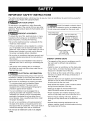 3
3
-
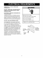 4
4
-
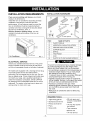 5
5
-
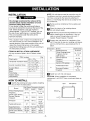 6
6
-
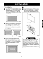 7
7
-
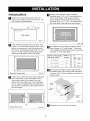 8
8
-
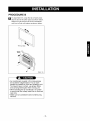 9
9
-
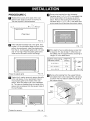 10
10
-
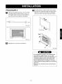 11
11
-
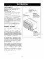 12
12
-
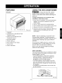 13
13
-
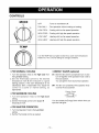 14
14
-
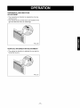 15
15
-
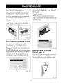 16
16
-
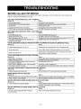 17
17
-
 18
18
-
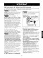 19
19
-
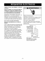 20
20
-
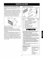 21
21
-
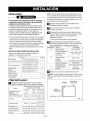 22
22
-
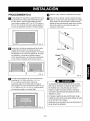 23
23
-
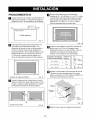 24
24
-
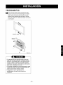 25
25
-
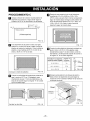 26
26
-
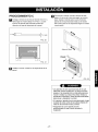 27
27
-
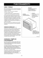 28
28
-
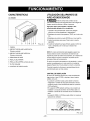 29
29
-
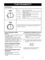 30
30
-
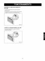 31
31
-
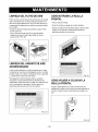 32
32
-
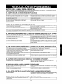 33
33
-
 34
34
-
 35
35
-
 36
36


Kenmore 580.72087200 El manual del propietario
- Tipo
- El manual del propietario
- Este manual también es adecuado para
en otros idiomas
- English: Kenmore 580.72087200 Owner's manual
Artículos relacionados
-
Kenmore 75135 501 Manual de usuario
-
Kenmore 580.75119500 El manual del propietario
-
-
-
Kenmore 580.73093300 El manual del propietario
-
-
-
Kenmore 25370066002 El manual del propietario
-