ESAB RT Robo Welding Torch System Manual de usuario
- Categoría
- Robótica
- Tipo
- Manual de usuario

Instrucciones de uso
0463 373 101 ES 20181227
RT Robo Welding Torch System
RTKS-2, RTFL-2, KSC-2, FLC-2, RT42, RT52,
RT62, RT72, RT82, RT42-NG, RT82WNG


TABLA DE CONTENIDO
0463 373 101 © ESAB AB 2018
1
SEGURIDAD................................................................................................ 5
1.1 Significado de los símbolos.................................................................. 5
1.2 Precauciones de seguridad................................................................... 5
2
GARANTÍA................................................................................................... 9
2.1 Condiciones de uso ............................................................................... 9
3
INTRODUCCIÓN.......................................................................................... 11
3.1 Descripción general de los sistemas de soplete de soldadura ......... 12
4
CARACTERÍSTICAS TÉCNICAS................................................................ 14
4.1 Cuello de soplete de soldadura ............................................................ 14
4.2 Tensión nominal ..................................................................................... 15
4.2.1 Límites del circuito de refrigeración...................................................... 16
4.3 Soporte del soplete ................................................................................ 16
4.3.1 Soportes de soplete para sistema RT estándar ................................... 16
4.3.1.1 Mecanismo de desconexión de seguridad RTKS-2 ......................... 17
4.3.1.2 Brida intermedia RTFL-2 .................................................................. 17
4.3.2 Soportes de soplete para sistema de muñeca hueca .......................... 18
4.3.2.1 Soporte de soplete con mecanismo de desconexión de seguridad
RT KSC-2 G/W..................................................................................
20
4.3.2.2 Soporte de soplete rígido con RT FLC-2 G/W................................... 21
4.4 Bridas de adaptador............................................................................... 21
4.5 Unidad de cables.................................................................................... 21
4.5.1 Unidades de cables de sistemas RT estándar..................................... 22
4.5.2 Unidades de cables para sistemas de muñeca hueca......................... 23
5
INSTALLATION............................................................................................ 25
5.1 RTKS-2 standard arm installation........................................................ 25
5.1.1 RTKS-2 safety-off mechanism............................................................. 25
5.1.1.1 Torch installation with adjustable mount............................................ 26
5.1.2 Standard arm cable assembly for KS-2 and FL-2 ................................ 28
5.1.3 RTKS-2 wire feeder connection........................................................... 29
5.1.4 RTKS-2 electrical connections ............................................................ 30
5.1.4.1 RTKS-2 safety-off mechanism connection ....................................... 30
5.1.5 RTKS-2 Torch installation .................................................................... 31
5.2 RTFL-2 standard arm installation ........................................................ 32
5.2.1 RTFL-2 rigid mount.............................................................................. 32
5.2.2 RTFL-2 torch installation ..................................................................... 34
5.3 RTKSC-2 hollow wrist system installation.......................................... 34
5.3.1 RTKSC-2 mount with safety off mechanism........................................ 34
5.3.2 Mounting the cable assembly............................................................... 35
5.3.2.1 RTKSC-2 feeder cabinet connections .............................................. 36
5.3.3 RTKSC-2 cable assembly ................................................................... 38
5.3.3.1 RTKSC-2 cable assembly installation .............................................. 38

TABLA DE CONTENIDO
0463 373 101 © ESAB AB 2018
5.3.3.2 RTKSC-2 electrical connections....................................................... 41
5.3.4 RTKSC-2 torch installation .................................................................. 42
5.4 RTFLC-2 installation.............................................................................. 43
5.4.1 RTFLC-2 mount................................................................................... 43
5.4.2 RTFLC-2 wire feeder connection......................................................... 43
5.4.2.1 Feeding through the robot arm.......................................................... 43
5.4.2.2 RTFLC-2 feeder cabinet connections............................................... 44
5.4.3 RTFLC-2 cable assembly .................................................................... 46
5.4.3.1 RTFLC-2 cable assembly installation ............................................... 46
5.4.4 RTFLC-2 electrical connections .......................................................... 49
5.4.4.1 RTFLC-2 hollow wrist system with Infiniturn cable assembly........... 49
5.4.4.2 RTFLC-2 hollow wrist system with Helix cable assembly................. 50
5.5 Torch installation.................................................................................... 50
5.5.1 Torch neck equipment .......................................................................... 50
5.5.2 Aristo RT torch neck installation ........................................................... 51
5.6 Installing the wire guide for standard and hollow Wrist arm ............. 52
5.6.1 Installing the neck liner......................................................................... 52
5.6.2 Installing a split wire guide in the cable assembly................................ 53
5.6.3 Installing a continuous wire guide in the cable assembly..................... 55
5.7 Adjust the narrow gap contact tip ........................................................ 56
6
OPERATION ................................................................................................ 59
6.1 Important information for programming (hollow wrist system only) 59
7
REPARACIÓN Y MANTENIMIENTO........................................................... 61
7.1 Comprobaciones y tareas obligatorias ................................................ 61
8
SOLUCIÓN DE PROBLEMAS .................................................................... 63
9
PEDIDOS DE REPUESTOS ........................................................................ 66
Reservado el derecho a modificar las especificaciones sin previo aviso.

1 SEGURIDAD
0463 373 101
- 5 -
© ESAB AB 2018
1 SEGURIDAD
1.1 Significado de los símbolos
Tal como se utilizan en este manual: Significa ¡Atención! ¡Cuidado!
¡PELIGRO!
Significa peligro inmediato que, de no evitarse, provocará de forma
inmediata lesiones personales graves o fatales.
¡ADVERTENCIA!
Significa que los riesgos potenciales pueden provocar daños personales,
que podrían ser fatales.
¡PRECAUCIÓN!
Significa que los riesgos podrían provocar lesiones personales leves.
¡ADVERTENCIA!
Antes de utilizar la unidad asegúrese de leer y
comprender el manual de instrucciones, y siga todas las
etiquetas, prácticas de seguridad de la empresa y hojas
de datos de seguridad (SDS, por sus siglas en inglés).
1.2 Precauciones de seguridad
Los usuarios de los equipos ESAB tienen la responsabilidad de asegurarse de que cualquier
persona que trabaje con el equipo o cerca de este respete todas las medidas de seguridad
necesarias. Las precauciones de seguridad deben cumplir los requisitos aplicables a este
tipo de equipo. Además de los reglamentos habituales de aplicación en el lugar de trabajo,
se deben respetar las siguientes recomendaciones.
Todas las tareas debe realizarlas personal cualificado que conozca bien el funcionamiento
del equipo. Una utilización incorrecta del equipo puede conducir a situaciones de riesgo que
ocasionen lesiones al operario y daños en el equipo.
1. Todas las personas que utilicen el equipo deben conocer:
○ su manejo
○ la ubicación de los botones de parada de emergencia
○ su funcionamiento
○ las medidas de seguridad aplicables
○ los procedimientos de soldadura y corte o cualquier otro trabajo que se pueda
realizar con el equipo
2. El operario debe asegurarse de que:
○ ninguna persona no autorizada se encuentre en la zona de trabajo al poner en
marcha el equipo
○ nadie está desprotegido cuando se inicia el arco o se empieza a trabajar con el
equipo
3. El lugar de trabajo debe:
○ ser adecuado para el uso que se le va a dar
○ estar protegido de corrientes de aire

1 SEGURIDAD
0463 373 101
- 6 -
© ESAB AB 2018
4. Equipo de seguridad personal:
○ Utilice siempre el equipo de protección personal recomendado (gafas
protectoras, prendas ignífugas, guantes…)
○ Evite llevar bufandas, pulseras, anillos y otros artículos que puedan
engancharse o provocar quemaduras.
5. Medidas generales de precaución:
○ Asegúrese de que el cable de retorno esté bien conectado
○ Solamente pueden trabajar en equipos de alta tensión electricistas
cualificados
○ Debe haber equipos de extinción de incendios adecuados claramente
identificados y a mano
○ Las tareas de lubricación y mantenimiento no se pueden llevar a cabo con el
equipo de soldadura en funcionamiento
¡ADVERTENCIA!
La soldadura y el corte por arco pueden producirle lesiones a usted mismo y a los
demás. Adopte las debidas precauciones al cortar o soldar.
DESCARGAS ELÉCTRICAS. Pueden causar la muerte.
• Instale la unidad y conéctela a tierra tal y como se explica en el manual de
instrucciones.
• No toque piezas o electrodos eléctricamente vivos con la piel
directamente, ropa o guantes húmedos.
• Aíslese de la pieza de trabajo y de tierra.
• Asegúrese de que su posición de trabajo es segura
LOS CAMPOS ELÉCTRICOS Y MAGNÉTICOS pueden ser peligrosos para
la salud
• Los soldadores que tengan implantado un marcapasos deben consultar a
su médico antes de soldar. Los campos electromagnéticos (CEM) pueden
interferir con algunos marcapasos.
• La exposición a los CEM puede tener otros efectos en la salud que son
desconocidos.
• Los soldadores deben usar los siguientes procedimientos para minimizar
la exposición a los CEM:
○ Tienda los cables del electrodo y de trabajo juntos por el mismo lado
del cuerpo. Fíjelos con cinta adhesiva cuando sea posible. No
coloque su cuerpo entre el soplete y los cables de trabajo. Nunca se
enrolle el soplete o los cables de trabajo alrededor del cuerpo.
Mantenga la fuente de alimentación y los cables de soldadura tan
alejados del cuerpo como sea posible.
○ Conecte el cable de trabajo a la pieza lo más cerca posible de la
zona de soldadura.
HUMOS Y GASES. Pueden ser peligrosos para la salud.
• Mantenga la cabeza alejada de los humos.
• Utilice ventilación, extracción en el arco, o ambos, para extraer los humos
y gases de la zona para respirar y el área general.

1 SEGURIDAD
0463 373 101
- 7 -
© ESAB AB 2018
RADIACIONES PROCEDENTES DEL ARCO. Pueden ocasionar lesiones
oculares y quemaduras cutáneas.
• Protéjase los ojos y el cuerpo en general. Utilice una máscara de
soldadura y unos lentes filtrantes adecuados y lleve ropa de protección
• Proteja asimismo a los que le rodean utilizando las pantallas y cortinas
pertinentes.
RUIDO. Un nivel de ruido excesivo puede causar lesiones de oído.
Protéjase los oídos. Utilice protectores auriculares u otro dispositivo de
protección similar.
PIEZAS MÓVILES - pueden causar lesiones
• Mantenga todas las puertas, paneles y cubiertas cerrados y asegurados
en su lugar. Sólo personas cualificadas deben quitar las cubiertas para el
mantenimiento y la solución de problemas cuando sea necesario. Vuelva a
colocar los paneles o tapas y cierre las puertas cuando el servicio haya
finalizado y antes de arrancar el motor.
• Pare el motor antes de instalar o conectar la unidad.
• Mantenga las manos, el pelo, la ropa holgada y las herramientas alejados
de las partes móviles.
RIESGO DE INCENDIO.
• Las chispas (salpicaduras) pueden provocar un incendio. Asegúrese de
que no hay materiales inflamables cerca.
• No utilice la unidad en contenedores cerrados.
FALLOS DE FUNCIONAMIENTO. En caso de que el equipo no funcione
correctamente, pida ayuda a un experto
PROTÉJASE Y PROTEJA A LOS DEMÁS
¡PRECAUCIÓN!
Este producto está destinado exclusivamente a soldadura por arco.
¡ADVERTENCIA!
No utilice la fuente de corriente de soldadura para descongelar tubos congelados.
¡PRECAUCIÓN!
Los equipos de clase A no son adecuados para uso en
locales residenciales en los que la energía eléctrica
proceda de la red pública de baja tensión. En tales
lugares puede resultar difícil garantizar la
compatibilidad electromagnética de los equipos de
clase A, debido tanto a perturbaciones conducidas
como radiadas.

1 SEGURIDAD
0463 373 101
- 8 -
© ESAB AB 2018
¡NOTA!
¡Elimine los aparatos electrónicos en una
instalación de reciclado!
De conformidad con la Directiva europea 2012/19/CE
sobre residuos de aparatos eléctricos y electrónicos y
su aplicación con arreglo a la normativa nacional, los
aparatos eléctricos o electrónicos que han llegado al
final de su vida útil se deben eliminar en una instalación
de reciclado.
Como responsable del equipo, le corresponde
informarse sobre los puntos de recogida autorizados.
Si desea más información, póngase en contacto con el
distribuidor ESAB más cercano.
ESAB comercializa un amplio surtido de accesorios de soldadura y equipos de
protección personal. Para obtener información sobre cómo adquirirlos, póngase en
contacto con su distribuidor local de ESAB o visite nuestro sitio web.

2 GARANTÍA
0463 373 101
- 9 -
© ESAB AB 2018
2 GARANTÍA
Nuestros productos se comprueban cuidadosamente antes de su entrega. ESAB verifica que
todos nuestros productos están en perfectas condiciones, sin defectos de materiales ni
fabricación en el momento de su entrega y que funcionan según el uso para el que se han
fabricado.
ESAB ofrece garantía sobre defectos de materiales y fabricación según los requisitos
legales. Los consumibles están exentos de esta garantía.
La garantía no cubre daños ni defectos funcionales derivados de:
• sobrecarga, mal uso del producto o uso distinto al previsto
• colisiones o accidentes
• incumplimiento de las instrucciones indicadas es estas instrucciones de
funcionamiento
• instalación o montaje incorrectos
• mantenimiento insuficiente
• modificación del estado original del producto
• efecto de productos químicos
• desgaste normal
ESAB no asume otra responsabilidad más que la sustitución o reparación de las piezas
defectuosas.
2.1 Condiciones de uso
1. El producto está destinado para uso industrial y comercial y sólo debe ser utilizado
por personal capacitado. El fabricante no se responsabiliza de cualquier daño o
accidente derivado del uso incorrecto.
2. El sistema de soldadura por robot Aristo® RT se ha diseñado y fabricado conforme a
la más moderna tecnología y garantiza su fiabilidad si las tareas de manejo,
instalación y mantenimiento las lleva a cabo personal con la debida formación. Deben
seguirse las instrucciones de instalación, uso y mantenimiento del presente
documento.
3. Solo personal capacitado está autorizado a instalar, manejar y reparar el sistema de
soldadura por robot Aristo® RT. Deben seguirse las instrucciones de instalación,
manejo y mantenimiento indicadas en este manual.
4. El sistema de soldadura por robot Aristo® RT debe utilizarse exclusivamente para la
finalidad prevista por el fabricante en el marco de sus datos técnicos y con sistemas
de manejo automatizados. El tipo de soplete seleccionado debe ajustarse a la tarea
de soldadura.
5. El sistema de soldadura por robot Aristo® RT se ha diseñado para utilizarse como un
sistema completo. No se permite incorporar en el sistema componentes de otros
fabricantes.
6. Los soportes de soplete RT KS-2 y RT KSC-2 solo deben utilizarse a modo de
mecanismos de parada de emergencia conforme a su marco de especificaciones
técnicas y junto con un juego de cables de brazo estándar de RT (KS-2), o bien una
unidad de cables Infiniturn o Helix (KSC-2); una brida de adaptador de ESAB,
incluidos soportes de soplete de RT (KS-2), y un soplete de soldadura Aristo RT.
7. No deben añadirse aceite ni líquido antisalpicaduras al gas de soplado. ESAB no
garantiza la resistencia química a estas sustancias. ESAB recomienda utilizar la
unidad de pulverización de ESAB para aplicar la cantidad mínima de líquido
antisalpicaduras al soplete y, por consiguiente, proteger el medio ambiente.

2 GARANTÍA
0463 373 101
- 10 -
© ESAB AB 2018
8. El producto debe mantenerse seco y protegido de la humedad cuando se transporte,
almacene y utilice.
9. El sistema está diseñado para temperaturas ambiente de entre 5 °C y 40 °C (41 a 104
°F). En caso de superar estos límites, es necesario adoptar medidas específicas. Si
existe riesgo de heladas, utilice un refrigerante adecuado.

3 INTRODUCCIÓN
0463 373 101
- 11 -
© ESAB AB 2018
3 INTRODUCCIÓN
Los sistemas de soplete de soldadura RT se han desarrollado para soldaduras MIG/MAG
totalmente automáticas mediante robot soldador. Estos sistemas constan de diferentes
cuellos de soplete Aristo RT diseñados para utilizarse robóticamente, soportes de soplete,
unidades de cables optimizadas para el uso robótico y funciones de desconexión de
seguridad que evitan daños en los sistemas en caso de colisión.
El sistema de soldadura RT estándar proporciona protección contra colisiones por medio del
RTKS-2, una función de desconexión de seguridad con presión de resorte mecánica.
Opcionalmente, es posible sustituirlo por la brida intermedia RTFL-2 para disfrutar de la
función de detección de colisiones del sistema de control por robot. El sistema de soldadura
RT estándar puede utilizarse con diversos tipos de unidades de cables.
Los soportes de soplete con RTKSC-2 y RTFLC-2 y unidades de cables Infiniturn o Helix
están pensados para utilizarse con sistemas de soldadura por robots de muñeca hueca
diseñados para aplicaciones de soldadura avanzadas. El mecanismo de desconexión de
seguridad del soporte de soplete con RT KSC-2 permite al soplete doblarse elásticamente
una distancia considerable en caso de colisión. Las unidades de cables Infiniturn y Helix son
fáciles de instalar y ofrece un sistema de alta fiabilidad con capacidades de maniobra
precisas.
Junto con los ya consolidados sopletes de soldadura por robot Aristo RT, estos componentes
conforman un sistema de gran fiabilidad y prolongada vida útil que necesita de las mínimas
tareas de mantenimiento.
El manual de instrucciones se entrega junto con los soportes de soplete y las unidades de
cables.
Los números de referencia de ESAB, los accesorios disponibles, los repuestos y los
consumibles se indican en la lista de repuestos.

3 INTRODUCCIÓN
0463 373 101
- 12 -
© ESAB AB 2018
3.1 Descripción general de los sistemas de soplete de soldadura
Sistema RT estándar
Para conocer una descripción detallada,
consulte la sección correspondiente del
capítulo CARACTERÍSTICAS TÉCNICAS:
1. Cuello del soplete
Consulte Soplete de soldadura.
2. Unidad de cables
Consulte Unidades de cables de
sistemas RT estándar.
3. Soporte del soplete
Consulte Soportes de soplete para
sistema RT estándar.
4. Mecanismo de desconexión de
seguridad RTKS-2
Consulte Mecanismo de
desconexión de seguridad RTKS-2.
5. Brida intermedia RTFL-2
Consulte Brida intermedia RTFL-2.
6. Brida de adaptador (si procede)
Consulte Bridas de adaptador.

3 INTRODUCCIÓN
0463 373 101
- 13 -
© ESAB AB 2018
Sistema de muñeca hueca
Para conocer una descripción detallada,
consulte la sección correspondiente del
capítulo CARACTERÍSTICAS TÉCNICAS:
1. Cuello del soplete
Consulte Soplete de soldadura.
2. Soporte de soplete con RT KSC-2
Consulte Soporte de soplete con RT
KSC-2 y mecanismo de
desconexión de seguridad.
3. Soporte de soplete con RTFLC-2
Consulte Soporte de soplete rígido
con RT FLC-2.
4. Brida de adaptador
Consulte Bridas de adaptador.
5. Unidad de cables Helix o
Infiniturn
Consulte Unidades de cables para
sistemas de muñeca hueca.

4 CARACTERÍSTICAS TÉCNICAS
0463 373 101
- 14 -
© ESAB AB 2018
4 CARACTERÍSTICAS TÉCNICAS
4.1 Cuello de soplete de soldadura
Elija el modelo de soplete en función de la aplicación de soldadura. Deben tenerse en
cuenta el ciclo de trabajo y la capacidad necesarios, el método de refrigeración y el diámetro
del hilo. Si se produjera un aumento de las necesidades, por ejemplo debido al
precalentamiento de las piezas de trabajo, a una elevada reflexión de calor en esquinas,
etc., deben tenerse en cuenta estos factores al elegir un soplete de soldadura con suficiente
reserva de potencia nominal.
Los sopletes de soldadura RT están diseñados para su uso con fuentes de corriente para
soldar conformes a las normativas CE para los procesos de soldadura de metal en
atmósfera de gas inerte (MIG), soldadura de metal en atmósfera de gas activo (MAG) y
soldadura fuerte MIG con hilos tubulares comercializados. No utilice el soplete para otros
procesos.
Para las tareas de soldadura por arco pulsado o soldadura de aluminio debe utilizarse el
soplete refrigerado por agua RT82W.
Consulte a continuación los modelos de soplete disponibles.
Modelo de soplete
Método de
refrigeración
Gas protector Valor de potencia
nominal
RT42G Refrigerado por gas CO
2
420A / 60%
Refrigerado por gas 300A / 100%
Refrigerado por gas Mezcla 350A / 60%
Refrigerado por gas 250A / 100%
RT42W Refrigerado por agua CO
2
420A / 60%
Refrigerado por agua 420A / 100%
Refrigerado por agua Mezcla 350A / 60%
Refrigerado por agua 350A / 100%
RT52G Refrigerado por gas CO
2
420A / 60%
Refrigerado por gas 300A / 100%
Refrigerado por gas Mezcla 350A / 60%
Refrigerado por gas 250A / 100%
RT52W Refrigerado por agua CO
2
470A / 60%
Refrigerado por agua 470A / 100%
Refrigerado por agua Mezcla 400A / 60%
Refrigerado por agua 400A / 100%
RT62G Refrigerado por gas CO
2
500A / 60%
Refrigerado por gas 340A / 100%
Refrigerado por gas Mezcla 420A / 60%
Refrigerado por gas 290A / 100%
RT62W Refrigerado por agua CO
2
530A / 60%
Refrigerado por agua 530A / 100%
Refrigerado por agua Mezcla 450A / 60%
Refrigerado por agua 450A / 100%

4 CARACTERÍSTICAS TÉCNICAS
0463 373 101
- 15 -
© ESAB AB 2018
Modelo de soplete
Método de
refrigeración
Gas protector Valor de potencia
nominal
RT72G Refrigerado por gas CO
2
480A / 60%
Refrigerado por gas 320A / 100%
Refrigerado por gas Mezcla 400A / 60%
Refrigerado por gas 270A / 100%
RT72W Refrigerado por agua CO
2
480A / 60%
Refrigerado por agua 430A / 100%
Refrigerado por agua Mezcla 480A / 60%
Refrigerado por agua 430A / 100%
RT82W Refrigerado por agua CO
2
600A / 60%
Refrigerado por agua 600A / 100%
Refrigerado por agua Mezcla 550A / 60%
Refrigerado por agua 550A / 100%
Los valores de potencia nominal del soplete y de ciclo de trabajo corresponden a un ciclo de
10minutos.
Las características técnicas son válidas para aplicaciones normalizadas en las que se
empleen los consumibles y repuestos estándar. El valor de potencia nominal del soplete se
reduce si se utiliza el modo de transferencia de arco metálico pulsado.
Intervalos de temperatura Almacenamiento: -15-50°C (5-122°F)
Uso: 5-40°C (41-104°F)
Gas de soplado Como máx. 10 bares, manguera de gas
independiente
Peso total (cuello del soplete, mecanismo de
desconexión de seguridad, soporte del
soplete y unidad de cables de 1m)
Aproximadamente 5kg
4.2 Tensión nominal
Tensión/amperaje máximos permitidos
Sistema completo de soplete de soldadura 141V (valor máximo para tareas de
soldadura)
Circuito de control de desconexión de
seguridad del RT KS-2
Botón pulsador del RT KS-2
24V / 1A
48V / 0,1A
Circuito de control de seguridad del RT
KSC-2
48 V
Uso de la función de detección de boquilla
con una unidad de cables estándar
50V / 5A
(Carga máxima permitida durante 1 minuto al
valor de corriente nominal)
Uso de la función de detección de boquilla
con unidades de cables Helix o Infiniturn
50V / 5A
(Carga máxima permitida durante 1 minuto al
valor de corriente nominal)

4 CARACTERÍSTICAS TÉCNICAS
0463 373 101
- 16 -
© ESAB AB 2018
Los valores indicados se refieren a un uso estándar.
Para conocer los valores nominales de las unidades de cables, consulte la sección Unidades
de cables.
4.2.1 Límites del circuito de refrigeración
Datos válidos únicamente para la versión refrigerada por agua.
Caudal de agua mín.: 1,0 l/min (1,1 qt/min)
Presión del agua mín.: 2,5bares (36,3 psi)
Presión del agua máx.: 3,5bares (50,8 psi)
Temperatura de entrada: máx. 40 °C (104 °F)
Temperatura de retorno: máx. 60 °C (140 °F)
Capacidad de refrigeración: mín. 1000W, en función de la aplicación
¡PRECAUCIÓN!
Las temperaturas superiores a 60 °C (140 °F) pueden dañar o destruir la unidad de
cables.
4.3 Soporte del soplete
El tipo de soporte de soplete necesario depende del diseño del sistema de soplete de
soldadura RT y de los dispositivos de desconexión de seguridad seleccionados; consulte la
sección Descripción general de los sistemas de soplete de soldadura.
Componente Peso aproximado
Soporte de soplete (para sistema estándar) 0,43 kg
Mecanismo de desconexión de seguridad RT
KS-2 (para sistema estándar)
0,85 kg
Brida intermedia RT FL-2 (para sistema
estándar)
0,35 kg
Soporte de soplete con RT KSC-2 (para
sistema de muñeca hueca)
1,90 kg
Soporte de soplete rígido con RT FLC-2
(para sistema de muñeca hueca)
1,22 kg
Soplete de soldadura por robot 0,66 kg
4.3.1 Soportes de soplete para sistema RT estándar
En los sistemas RT estándar, el soporte del soplete se instala en el mecanismo de
desconexión de seguridad RTKS-2 (u, opcionalmente, en la brida intermedia RTFL-2),
donde fija la unidad de cables y el cuello del soplete conectado.
Seleccione el soporte de soplete en función del tipo de soplete y de su geometría. Se
pueden utilizar distintos tipos de soporte. Consulte la lista de repuestos para conocer los
soportes de soplete disponibles para sistema RT estándar.

4 CARACTERÍSTICAS TÉCNICAS
0463 373 101
- 17 -
© ESAB AB 2018
Soporte de soplete para robots de brazo estándar
4.3.1.1 Mecanismo de desconexión de seguridad RTKS-2
El mecanismo de seguridad RT KS-2 es un dispositivo apoyado en resorte que protege el
robot y el sistema de soplete en caso de colisión.
¡NOTA!
No desmonte el RT KS-2.
4.3.1.2 Brida intermedia RTFL-2
Es posible utilizar la brida intermedia rígida RT FL-2 en lugar del RT KS-2 si el robot
dispone de un sistema de detección electrónica de colisiones.

4 CARACTERÍSTICAS TÉCNICAS
0463 373 101
- 18 -
© ESAB AB 2018
4.3.2 Soportes de soplete para sistema de muñeca hueca
En el sistema de muñeca hueca, los cuellos del soplete de soldadura Aristo RT están
conectados al soporte de soplete con KSC-2 o FLC-2.
El soporte de soplete con RT KSC-2 permite al soplete doblarse elásticamente en caso de
colisión. Al mismo tiempo se abre un contacto eléctrico, que indica al control del robot que
debe detenerse. Después de haber restablecido el error, se alcanzarán los valores de
geometría y punto central de herramienta (TCP) del soplete con alta precisión. El sistema
funciona de manera enteramente mecánica y está presionado mediante resorte.
El soporte de soplete con RTFLC-2 no cuenta con función de desconexión de seguridad
integrada.
En sistemas de muñeca hueca, se recomienda utilizar el RTKSC-2 G/W (opcionalmente, el
RTFLC-2 G/W). Este soporte de soplete puede utilizarse tanto con soportes refrigerados por
gas como refrigerados por agua de la serie Aristo RT.
RTKSC-2 G/W RTFLC-2 G/W
Principio de funcionamiento
del mecanismo de
desconexión de seguridad
Mecánico No procede (soporte rígido)
Fuerza de liberación axial
(Fz)
650 N No procede (soporte rígido)
Par de liberación en el eje
transversal (Mx)
24 Nm No procede (soporte rígido)
Restablecimiento tras la
liberación
Automatic No procede (soporte rígido)
Repetibilidad ±0,1mm laterales en el TCP
de un soplete Aristo RT
estándar
No procede (soporte rígido)
Capacidad de dobladura
máx.
Aprox. ±8° No procede (soporte rígido)

4 CARACTERÍSTICAS TÉCNICAS
0463 373 101
- 19 -
© ESAB AB 2018
Interruptor de seguridad Normalmente cerrado
Carga eléctrica máx. 48 V / 1
A
No procede (soporte rígido)
Circuito de control eléctrico
de la función de detección de
boquilla
Valor nominal:
• Unidades de cables
Helix: como máx. 50 V
de CC/5 A, como máx. 1
minuto
Tras la detección del
contacto, desconecte
rápidamente la tensión
de detección.
• En las unidades de
cables Infiniturn, la
función de detección de
boquilla está limitada.
Póngase en contacto
con ESAB para que
efectúen una
investigación minuciosa
de las posibles
soluciones para su
aplicación.
Valor nominal:
• Unidades de cables
Helix: como máx. 50 V
de CC/5 A, como máx.
1 minuto
• Unidades de cables
Infiniturn: como máx. 50
V de CC/1 A, como
máx. 1 minuto
Tras la detección del
contacto, desconecte
rápidamente la tensión de
detección.
Tensión nominal Tensión máxima permitida del
circuito de control de
seguridad: 48V.

4 CARACTERÍSTICAS TÉCNICAS
0463 373 101
- 20 -
© ESAB AB 2018
4.3.2.1 Soporte de soplete con mecanismo de desconexión de seguridad RT KSC-2
G/W
Elem
ento
Descripción Función
1 Soporte del cuello del soplete Punto de conexión con el soplete Aristo RT
2 Cubierta del RT KSC-2 Conjunto con cable y puntos de conexión con el
soplete
3 Funda de goma Protección del mecanismo de desconexión de
seguridad
4 Cuerpo principal del RT KSC-2 Permite la dobladura mecánica en caso de colisión
5 Brida de adaptador Punto de conexión de aislamiento de la muñeca del
robot (debe ajustarse al robot concreto)
6 Pasador de índice Para una alineación precisa con la brida del
adaptador
7 Conector para el cable de
control
Conexión eléctrica para señal de colisión y la
función de detección de boquilla
8 Microinterruptor Sensor para la detección de colisiones

4 CARACTERÍSTICAS TÉCNICAS
0463 373 101
- 21 -
© ESAB AB 2018
4.3.2.2 Soporte de soplete rígido con RT FLC-2 G/W
Elem
ento
Descripción Función
1 Soporte del cuello del soplete Punto de conexión con el soplete Aristo RT
2 Cubierta de la RT FLC-2 Conjunto con cable y puntos de conexión con el
soplete
3 Cuerpo principal de la
RTFLC-2
Permite la dobladura mecánica en caso de colisión
4 Pasador de índice Para una alineación precisa con la brida del
adaptador
5 Brida de adaptador Punto de conexión de aislamiento de la muñeca del
robot (debe ajustarse al robot concreto)
6 Conector para el cable de
control (3 polos)
Conexión eléctrica para la función de detección de
boquilla (si procede)
4.4 Bridas de adaptador
Seleccione la brida de adaptador necesaria para la instalación del brazo del robot en función
del correspondiente tipo del robot. Hay disponibles bridas de adaptador para todos los
sistemas estándar y de muñeca hueca; consulte la lista de repuestos.
4.5 Unidad de cables
La conexión al alimentador de hilo de soldadura se ve afectada por la unidad de cables. Las
versiones principales dependen principalmente del diseño del sistema y del medio de
refrigeración (gas o agua); consulte la lista de repuestos.

4 CARACTERÍSTICAS TÉCNICAS
0463 373 101
- 22 -
© ESAB AB 2018
Los valores son válidos para cables con una longitud de 1 a 5 m.
Unidad de cables
estándar
Infiniturn Helix
Valor nominal (ciclo
de 10 minutos)
Refrigerado por gas
(mezcla de gases)
Ciclo de trabajo de
500 A / 60 % como
máx.
Ciclo de trabajo de
350 A / 100 % como
máx.
Ciclo de trabajo de
400 A / 60 % como
máx.
Ciclo de trabajo de
320 A / 100 % como
máx.
Ciclo de trabajo de
400 A / 60 % como
máx.
Ciclo de trabajo de
320 A / 100 % como
máx.
Valor nominal (ciclo
de 10 minutos)
Refrigerado por agua
Ciclo de trabajo de
600 A / 100 % como
máx.
Ciclo de trabajo de
550 A / 100 % como
máx.
Ciclo de trabajo de
550 A / 100 % como
máx.
Rango de giro Capacidad de giro
limitada
Giro ilimitado ±270° desde la
posición neutra
Peso
Refrigerado por gas
1,2 m de largo:
2,35 kg
1,0 m de largo:
2,0 kg
1,0 m de largo:
2,0 kg
Peso
Refrigerado por agua
1,2 m de largo:
2,35 kg
1,0 m de largo:
2,0 kg
1,0 m de largo:
2,0 kg
4.5.1 Unidades de cables de sistemas RT estándar
Pines de conector Burndy
A. Boquilla de gas con
detección de contacto
C. Sensor de colisión
D. Sensor de colisión
E. Alimentación de hilo
F. 0V
G. Tensión positiva (+) del
motor
H. Tensión negativa (−) del
motor
Elem
ento
Descripción Función
1 Brida de soporte del cuello Punto de conexión con el soplete
2 Cubierta protectora Protege la unidad de cables contra daños

4 CARACTERÍSTICAS TÉCNICAS
0463 373 101
- 23 -
© ESAB AB 2018
Elem
ento
Descripción Función
3 Conector Burndy, 12 polos Conexión eléctrica entre el dispositivo de
desconexión de seguridad y el alimentador de hilo
4 Cable de control Para KS-2 (desconexión de seguridad y botón
pulsador)
5 Conector EURO Conexión del alimentador de hilo
6 Manguera de soplado (tapón
negro)
Para limpiar el soplete con aire comprimido después
de un ciclo de limpieza
7 Entrada de agua (tapón azul)
Entrada de agua para la refrigeración del soplete
1)
8 Retorno del agua (tapón rojo)
Retorno del agua caliente del soplete
1)
9 Conexión del cable de control
del mecanismo de desconexión
de seguridad
Conexión eléctrica con el RTKS-2 para la señal de
desconexión de seguridad y la función de detección
de boquilla
1)
Solo sistemas de soplete refrigerados por agua
4.5.2 Unidades de cables para sistemas de muñeca hueca
La unidad de cables Infiniturn permite un giro ilimitado del soplete en ambos sentidos. Al
mismo tiempo, se transfieren el líquido refrigerante, el gas protector, el aire de soplado, la
alimentación de soldadura y la señal del mecanismo de desconexión de seguridad.
La unidad de cables Helix está diseñada para un rango de giro de ±270° desde la posición
neutra. Se puede utilizar para trabajos de soldadura que no necesiten de giro ilimitado.
Las unidades de cables Infiniturn están disponibles en versiones refrigeradas por gas y
agua. Las unidades de cable Helix pueden utilizarse universalmente para aplicaciones
refrigeradas por gas o agua.
¡NOTA!
No conecte ninguna unidad de cables Helix accionada mediante cuello de soplete
refrigerado por gas conectado a un sistema de refrigeración por agua.

4 CARACTERÍSTICAS TÉCNICAS
0463 373 101
- 24 -
© ESAB AB 2018
Elem
ento
Descripción Función
1 Brida Punto de conexión con el soporte de soplete con RT
KSC-2 o RTFLC-2
2 Pasador de índice Garantiza una orientación correcta del acoplamiento
3 Conector del cable de control Conexión eléctrica con el RTKSC-2 para la señal
de desconexión de seguridad y la función de
detección de boquilla (si procede)
4 Conector EURO Conexión del alimentador de hilo
5 Cable de control Conexión eléctrica de la señal de desconexión de
seguridad (del RTKSC-2) y la función de detección
de boquilla (la detección de boquilla está incluida de
serie en el modelo Helix, no en el Infiniturn)
6 Retorno del agua (tapón rojo) Retorno del agua caliente del soplete
7 Entrada de agua (tapón azul) Entrada de agua para la refrigeración del soplete
8 Manguera de soplado (tapón
negro)
Para limpiar el soplete con aire comprimido después
de soldar
9 Acoplamiento de medio Acoplamiento de giro ilimitado con transferencia de
medio
10 Cubierta protectora Protege la unidad de cables contra daños

5 INSTALLATION
0463 373 101
- 25 -
© ESAB AB 2018
5 INSTALLATION
¡ADVERTENCIA!
For your own safety, make sure that the robot is either in standby or power-less
state before doing maintenance work in the moving radius of the robot.
Follow the assembly instructions exactly. Pay attention during assembly that the cables are
not damaged. Damaged cables can lead to a short circuit, which may damage the electronics
of the robot or the welding torch.
Use only original ESAB components that have been specially developed for this purpose.
Only then the correct functioning of the whole welding torch system can be guaranteed.
5.1 RTKS-2 standard arm installation
5.1.1 RTKS-2 safety-off mechanism
1. Dismount the insulation flange (10) from the RTKS-2 (11) by removing the screws
(12).
2. Position the insulation flange (10) with the index pin on the robot arm and fix it with the
screws (20) included.
The insulation flange (10) is directly compatible with robots with tool flange according
to DIN ISO 9409-1-A40 (diameter 40mm, 4×M6). If the insulation flange (10) does
not fit, use an adapter flange (21).
¡NOTA!
Ensure that the index pin is located correctly. The maximum torque of 1.2Nm
(10.5in.lb) must be observed for the fastening of the adapter flange screws.
Prevent self-loosening of the screws by using suitable thread locking
measures.
3. Mount the RTKS-2 the back on the insulation flange (10).

5 INSTALLATION
0463 373 101
- 26 -
© ESAB AB 2018
4. Position the mount on the RTKS-2 and carefully insert the cylindrical pins (14) into the
holes provided. Take the position of the torch into account. Two mounting positions
may be potentially possible.
5. Screw the mount evenly using the enclosed cylinder screws with hexagon socket (12).
¡NOTA!
The maximum tightening torque for the cylinder screw (5) is 6Nm (53in.lb)
and the property class category is 8.8.
12 - Cylinder screw with hexagon socket
M6DIN912 (length of the screw depending
on the torch mount)
14 - Cylindrical pins Ø4×20
5.1.1.1 Torch installation with adjustable mount
Torch mounts with a central clamping assembly can only be fastened on the journal of the
mounting flange. For this, the mounting flange must be fastened first.
1. If applicable, carefully press the cylindrical pins (1) into the corresponding holes in the
mounting flange. The pins should protrude by approximately 5 mm (0.2 in.).
2. Position the mount on the safety-off mechanism RTKS-2 and carefully insert the
cylindrical pins (1) into the holes provided. In doing so, take the later position of the
torch into account. Two mounting positions may be potentially possible.
3. Then screw down the mounting flange evenly using the enclosed cylinder screws with
hexagon socket (2).
¡NOTA!
The maximum tightening torque for the cylinder screw (2) is 7.1 Nm (62.8
in.lb) and the property class category is 8.8.

5 INSTALLATION
0463 373 101
- 27 -
© ESAB AB 2018
4. Unscrew the axial cylinder screw with hexagon socket (4) out of the mounting flange
together with the washer (3).
1 - Cylindrical pins Ø4×14 3 - Washer Ø9 mm
2 - Cylinder screw with hexagon socket
M6×16
4 - Axial cylinder screw with hexagon
socket M8×16
5. Place the torch mount (5) onto the journal (6) of the mounting flange, paying attention
while doing so to the exact alignment of the feather key (7) and the corresponding
groove (7a).
6. Insert the clamping mandrel (8) into the lateral hole (see illustration) and position it so
that the mating surfaces (9a) of the clamping mandrel rest on the mating surface (9) of
the journal.

5 INSTALLATION
0463 373 101
- 28 -
© ESAB AB 2018
7. Fix the clamping mandrel from the opposite side using the M6 cylinder screw with
hexagon socket (10) and the Ø22 mm washer (11).
8. Screw the axial cylinder screw (4) with the Ø9 mm washer (3) into the mounting flange
and tighten firmly.
3 - Washer Ø9 mm 8 - Clamping mandrel
4 - Axial cylinder screw with hexagon
socket M8×16
9 - Mating surface of mounting flange
5 - Torch mount 9a - Mating surfaces of clamping mandrel
6 - Mounting flange journal 10 - Cylinder screw with hexagon socket
M6×30
7 Feather key 11 - Washer Ø22×6.4 mm
7a - Groove for feather key
5.1.2 Standard arm cable assembly for KS-2 and FL-2
The cable assembly must be aligned to the intended use in length and design. The type of
cooling for the torch and the cable assembly must be the same (either gas or water cooled
respectively). In order to prevent damage to the torch system and other components, it is
imperative to observe the following instructions.

5 INSTALLATION
0463 373 101
- 29 -
© ESAB AB 2018
¡PRECAUCIÓN!
• Coordinate the length and design of the cable assembly to suit the range of
action of the robot.
• Do not bend, compress or overstretch the cable assembly.
• Fix the cable assembly such that is can be moved freely and cannot become
entangled.
• Any additional holding devices possibly installed, for example a balancer,
must not crush or bend the cable assembly.
• Extreme turning movements must be avoided in which the cable assembly
may become twisted.
• Chafing on the robot or other objects must be excluded.
1. Unscrew the cylinder screws (1) and lift off the top section (2) of the torch mount.
2. Insert the feather key (4) into the recess of the neck support flange (3) from below.
3. Align the neck support flange (3) including the feather key (4) to the groove (5) of the
torch mount and push into the groove right up to the stop of the flange.
4. Hold the cable assembly in this position and simultaneously place the top section (2)
back onto the torch mount. First screw both cylinder screws (1) loosely in to about the
same length, then tighten alternately. The top section (2) of the mount should have an
even gap to the bottom section.
The front part of the cable assembly is directly clamped into the torch mount (see
illustration below).
1 - Cylinder screws 4 - Feather key
2 - Torch mount top section 5 - Groove for feather key
3 - Neck support flange
5.1.3 RTKS-2 wire feeder connection
In order to be able to create the connection, the cable assembly must be mounted as
described in the "Installing the cable assembly" section and equipped following "Installing the
wire guide" section. Only then can the central and media connection take place. Proceed as
described below:

5 INSTALLATION
0463 373 101
- 30 -
© ESAB AB 2018
1. Connect the central connector of the cable assembly (2) to the wire feeder cabinet
socket. Tighten the central connector sleeve nut fingertight. Do not use tools.
1 - Burndy Connector 4 - Return of heated water (red cap)
2 - EURO central connector 5 - Return of heated water (red cap)
3 - Air blow-out 6 - Main Wire feeder
2. For water cooled systems. Connect the water hoses to the cooling circuit. The end of
the hose marked blue (4) is connected to the water outlet, and the end marked red (5)
is connected to the water return.
3. Connect the blow-out line (3) to the corresponding connection of the feeder.
4. Connect the Burndy Connector to the wire feeder. (1) to the feeder. See section
"Electrical connections".
¡NOTA!
All hoses and the control line must be installed so they can not bend or get
damaged!
5.1.4 RTKS-2 electrical connections
5.1.4.1 RTKS-2 safety-off mechanism connection
The switch for the safety-off functionality RTKS-2 is connected through the control cable,
see (3) in the illustration below. This connects to the RTKS-2 unit via the 4-pole plug (4) that
contains circuits for the push-button (6) and the safety-off signal (7).
If a collision is detected, the control circuit for the safety-off signal (7), which is normally
closed, will be interrupted.
Rating of the control circuit: max. 48 V / 1 A

5 INSTALLATION
0463 373 101
- 31 -
© ESAB AB 2018
2 - Burndy connector 5 - RTKS-2 connector for control cable plug
4 - Control cable plug
Pines de conector Burndy
A. Boquilla de gas con
detección de contacto
C. Sensor de colisión
D. Sensor de colisión
E. Alimentación de hilo
F. 0V
G. Tensión positiva (+) del
motor
H. Tensión negativa (−) del
motor
If the robot control provides a control circuit for nozzle sense functionality, the connection is
accomplished with a 1-wire connection.
Rating of the control circuit: max 50 V / 5 A.
¡PELIGRO!
If the nozzle sense function is not being used, the open end of the control cable on
the power source connection side must be properly isolated in order to avoid short
circuits. During certain problems on the torch head, the full welding potential may be
present on this cable.
¡PRECAUCIÓN!
After detection of contact (gas nozzle on work piece), quickly reduce or cut off the
maximum current in the nozzle sense circuit in order to avoid overloading of the
system.
Allowed load max. 1 minute at the rated nominal current.
5.1.5 RTKS-2 Torch installation
Continue according to section "Torch installation".

5 INSTALLATION
0463 373 101
- 32 -
© ESAB AB 2018
5.2 RTFL-2 standard arm installation
5.2.1 RTFL-2 rigid mount
1. Position the RT FL-2 (2) with the index pin on the robot arm and fix it with the hexagon
socket screw included.
The FL-2 is directly compatible with robots with tool flange according to DIN ISO
9409-1-A40 (diameter 40mm, 4×M6). If the rigid mount does not fit, use an adapter
flange (3).
¡NOTA!
Ensure that the index pin is located correctly. The maximum torque of 1.2Nm
(10.5in.lb) must be observed for the fastening of the adapter flange screws.
Prevent self-loosening of the screws by using suitable thread locking
measures.
2. Install torch mount (1). Only torch mounts having a hole pattern equivalent with the
mounting surface may be attached. If necessary, carefully press the cylindrical pins (4)
into the corresponding holes in the bracket. The pins should protrude by
approximately 5mm (0.2in.). Position the torch mount on the RTFL-2 (2) and
carefully insert the cylindrical pins (4) into the holes provided. Take the position of the
torch into account. Two mounting positions may be potentially possible.
3. Screw the mount evenly using the enclosed cylinder screws with hexagon socket (5).
¡NOTA!
The maximum tightening torque for the cylinder screw (5) is 6Nm (53in.lb)
and the property class category is 8.8.

5 INSTALLATION
0463 373 101
- 33 -
© ESAB AB 2018
Side view
4 - Cylindrical pins Ø4×20
5 - Cylinder screw with hexagon socket M6
DIN 912 (length of the screw depending on
the torch mount)
Torch installation with adjustable mount
Torch mounts with a central clamping assembly can only be fastened on the journal of the
mounting flange. For this, the mounting flange must be fastened first.
1. If applicable, carefully press the cylindrical pins (1) into the corresponding holes in the
mounting flange. Avoid the formation of burrs. The pins should protrude by
approximately 5 mm (0.2 in.).
2. Position the mount on the RTFL-2 and carefully insert the cylindrical pins (1) into the
holes provided. In doing so, take the later position of the torch into account. Two
mounting positions may be potentially possible.
3. Then screw down the mounting flange evenly using the enclosed cylinder screws with
hexagon socket (2).
¡NOTA!
The maximum tightening torque for the cylinder screw (2) is 7.1 Nm (62.8
in.lb) and the property class category is 8.8.
4. Unscrew the axial cylinder screw with hexagon socket (4) out of the mounting flange
together with the washer (3).
1 - Cylindrical pins Ø4×14 3 - Washer Ø9 mm
2 - Cylinder screw with hexagon socket
M6×16
4 - Axial cylinder screw with hexagon
socket M8×16
5. Place the torch mount (5) onto the journal (6) of the mounting flange, paying attention
while doing so to the exact alignment of the feather key (7) and the corresponding
groove (7a).

5 INSTALLATION
0463 373 101
- 34 -
© ESAB AB 2018
6. Insert the clamping mandrel (8) into the lateral hole (see illustration) and position it so
that the mating surfaces (9a) of the clamping mandrel rest on the mating surface (9) of
the journal.
7. Fix the clamping mandrel from the opposite side using the M6 cylinder screw with
hexagon socket (10) and the Ø22 mm washer (11).
8. Screw the axial cylinder screw (4) with the Ø9 mm washer (3) into the mounting flange
and tighten firmly.
3 - Washer Ø9 mm 8 - Clamping mandrel
4 - Axial cylinder screw with hexagon
socket M8×16
9 - Mating surface of mounting flange
5 - Torch mount 9a - Mating surfaces of clamping mandrel
6 - Mounting flange journal 10 - Cylinder screw with hexagon socket
M6×30
7 - Feather key 11 - Washer Ø22×6.4 mm
7a - Groove for feather key
5.2.2 RTFL-2 torch installation
Continue according to section "Torch installation".
5.3 RTKSC-2 hollow wrist system installation
5.3.1 RTKSC-2 mount with safety off mechanism
¡PRECAUCIÓN!
For hollow wrist systems make sure that the clear space around the robot is at least
Ø45 mm (1.8 in.) around the wrist and 50 mm (2.0 in.) near the wire feeder.

5 INSTALLATION
0463 373 101
- 35 -
© ESAB AB 2018
1. Remove the three screws (2) from the front cover (3) of the torch mount and carefully
pull the cover off the RTKSC-2 main body (5). Take care not to damage the micro
switches installed inside the assembly.
1 - Hexagon wrench 4 mm 4 - Rubber boot
2 - 3× M5×12 screws 5 - RT KSC-2 main body
3 - RT KSC-2 front cover
1. Pull off the rubber boot (4) from the RTKSC-2 main body (5) to the front.
2. Now position the RTKSC-2 main body (5) on the adapter flange (7) so that the index
pin is correctly seated. Attach with the screws (6) enclosed.
3. Reinstall the rubber boot (4) on the RTKSC-2 main body (5) and make sure it is
correctly located in the grooves on the front and back flange.
4. Istall the adapter flange (7) on the robot.
Fastening torque max. 2.2 Nm (19.5 in.lb).
1 - Hexagon wrench 4 mm 3 - 3× M5×12 hexagon socket screws
2 - Rubber boot 4 - Adapter flange
5.3.2 Mounting the cable assembly
¡NOTA!
In order to adjust the wire feeder position to the cable assembly length, it must be
mounted on an adjustable support with a possible movement of ±2-3cm (±1in.) to
the back and to the front. The length of the cable assembly must be determined
from the centred mounting position of the wire feeder.
1. Move the robot arm into a completely straight position, see illustration below. Make
sure that (1) axis 6 (rotation around the torch axis) is in 0° position.
2. Move the feeder (3) completely to the back in order to create space for inserting the
cable assembly. If it is not possible to move the feeder sufficiently, it should be
removed from the robot.

5 INSTALLATION
0463 373 101
- 36 -
© ESAB AB 2018
3. Insert the cable assembly with the coupling (2) first into the robot arm and feed it
through the robot wrist.
4. The feeder should only be installed again after the correct mounting position with
respect to the cable length has been determined. (See section "Installing the cable
assembly").
¡PRECAUCIÓN!
Axis 6 must be in 0° position.
5.3.2.1 RTKSC-2 feeder cabinet connections
When installed for the first time, the position of the wire feeder cabinet must be adjusted to
the length of the cable assembly. First, the robot arm must be fully extended (straight).
¡PRECAUCIÓN!
As long as the correct position of the feeder corresponding to the length of the cable
assembly has not been determined, be careful when moving the robot arm and
avoid overstretching the cable. It is helpful to loosen the positioning screws of the
feeder before moving the robot arm to allow the feeder to follow the cable assembly.

5 INSTALLATION
0463 373 101
- 37 -
© ESAB AB 2018
1. Loosen the sliding mechanism of the wire feeder and connect the cable assembly.
2. Now adjust the position of the wire feeder to suit the length of the Infiniturn or Helix
cable, as indicated with "A" in the illustration below.
¡PRECAUCIÓN!
When adjusting the position of the feeder cabinet, make sure that the cable
assembly is not under stress when the robot arm is in stretched-out position.
It is normal for the cable assembly to sag slightly, it should never be taut.
3. Before securing the wire feeder in its permanent position, ensure that the Euro
connectors are tightly connected. Then turn the torch mount down and up again
(rotating on the axis 5), in order not to tighten the cable assembly too much against
the feeder (see illustration above). Once this is done, tighten the feeder in that
position.
4. For water cooled systems, connect the water lines to the cooling circuit. See section
"Cable assemblies for hollow wrist systems" in the TECHNICAL DATA chapter for
indications.
The hose with the blue rubber cap is for cooling water to the torch, the hose with the
red rubber cap returns the heated water. Make sure the hoses will not kink or get
otherwise blocked.
¡NOTA!
A Helix cable assembly used for a gas cooled system must not be connected
to a cooling circuit. As the water connections are not needed, they may be cut
off.
5. Connect the blow-out hose (black rubber cap) to the corresponding outlet of the wire
feeder.
¡NOTA!
If the blow-out function is not used, the blow-out hose must be sealed with the
rubber cap enclosed. With Infiniturn systems, the blow-out air must be
supplied to the corresponding connection hose, if it is not permitted to connect
blow-out air to the shield gas connection!
6. Install the necessary plug on the control cable and connect it to the safety off circuit
interface of the wire feeder (see section "Electrical connections").

5 INSTALLATION
0463 373 101
- 38 -
© ESAB AB 2018
5.3.3 RTKSC-2 cable assembly
The cable assembly must be aligned to the intended use in length and design. The type of
cooling for the torch and the cable assembly must be the same (either gas or water cooled
respectively). In order to prevent damage to the torch system and other components, it is
imperative to observe the following instructions.
¡PRECAUCIÓN!
• Coordinate the length and design of the cable assembly to suit the range of
action of the robot.
• Do not bend, compress or overstretch the cable assembly.
• Fix the cable assembly such that is can be moved freely and cannot become
entangled.
• Any additional holding devices possibly installed, for example a balancer,
must not crush or bend the cable assembly.
• Extreme turning movements must be avoided in which the cable assembly
may become twisted.
• Chafing on the robot or other objects must be excluded.
5.3.3.1 RTKSC-2 cable assembly installation
¡NOTA!
For some robots, it may be possible to deviate from this order, and first connect the
cable assembly to the RTKSC-2, then thread the cable from the front through the
robot arm. If in doubt, follow the suggested order.
1. Loosen the three screws (7) with the associated washers and remove them from the
RTKSC-2 cover (1). See illustration below.
2. Install the supplied O-rings (4) into the grooves in the cover (1).
3. Pull the cable assembly approximately 15 cm (6 in.) from the main body (3).

5 INSTALLATION
0463 373 101
- 39 -
© ESAB AB 2018
4. Insert the coupling (2) into the socket of the cover (1) as shown. Align the index pin (6)
with the index hole (5) in the main body and insert completely.
¡NOTA!
Make sure that the position of the O-rings are not shifted by the index pin
during the assembly.
1 - RTKSC-2 cover 5 - Index hole
2 - Coupling 6 - Index pin
3 - RTKSC-2 main body 7 - 3× M5×35 screws
4 - 3× O-ring for water cooled systems 11 - Control cable connector
5. Insert the three screws (7) with the associated washers (8) and tighten gently with the
enclosed hexagonal wrench, see below illustration.
Fastening torque approximately 2 Nm (18 in.lb).

5 INSTALLATION
0463 373 101
- 40 -
© ESAB AB 2018
6. If present, insert the control cable plug (10) into the connector (11) and make sure it is
firmly seated.
7 - 3× M5×35 screw 11 - Control cable connector
8 - Washer 12 - 2× Micro switch
10 - Control cable plug 13 - Index pin
7. Gently push back the cable assembly into the robot arm and carefully seat the
RTKSC-2 cover (1) in place. Observe the index pin (13) to be in the correct position.
Make sure the two micro switches (12) are not damaged if present.
8. Insert the three M5 screws (14) and tighten without excessive force.
13. Index pin
14. 3× M5×12 screws

5 INSTALLATION
0463 373 101
- 41 -
© ESAB AB 2018
5.3.3.2 RTKSC-2 electrical connections
¡NOTA!
After connecting the control cable, secure the cable in order to protect it from getting
caught while the robot is moving.
Usually, the control cable will be directly connected to the wire feeder. See the
manufacturer's documentation for details. The link to the robot control is then
implemented via the power source controller.
RTKSC-2 safety-off mechanism connection
The switch for the safety-off functionality RTKSC-2 is connected through the control cable,
see (3) in the illustration below. This connects to the RTKSC-2 unit via the control cable plug
(1).
The safety-off signal requires a 2-wire connection (black/black) to the safety-off circuit in the
robot control (5).
If a collision is detected, the control circuit (normally closed) will be interrupted (4).
Rating of the control circuit: max. 48 V / 1 A.
1 - Control cable plug 3 - Burndy connector VVV
2 - EURO central connector
Pines de conector Burndy
A. Boquilla de gas con
detección de contacto
C. Sensor de colisión
D. Sensor de colisión
E. Alimentación de hilo
F. 0V
G. Tensión positiva (+) del
motor
H. Tensión negativa (−) del
motor
RTKSC-2 nozzle sense function connection
If the robot control provides a control circuit for nozzle sense functionality.
The connection is accomplished with a 2-wire connection (black/black) to the nozzle sense
circuit in the robot control (5), see illustration below.

5 INSTALLATION
0463 373 101
- 42 -
© ESAB AB 2018
Usually, the control cable will be directly connected to the wire feeder. See the
manufacturer's documentation for details. The link to the robot control is then implemented
via the power source robot interface.
Rating of the control circuit: max. 50 V / 5 A.
¡PELIGRO!
If the nozzle sense function is not being used, the open end of the control cable on
the power source connection side must be properly isolated in order to avoid short
circuits. During certain problems on the torch head, the full welding potential may be
present on this cable.
¡PRECAUCIÓN!
After detection of contact (gas nozzle on work piece), quickly reduce or cut off the
maximum current in the nozzle sense circuit in order to avoid overloading of the
system.
Allowed load max. 1 minute at the rated nominal current.
1 - Control cable plug 3 - Control cable
2 - EURO central connector
5.3.4 RTKSC-2 torch installation
Continue according to section "Torch installation".

5 INSTALLATION
0463 373 101
- 43 -
© ESAB AB 2018
5.4 RTFLC-2 installation
5.4.1 RTFLC-2 mount
1. Remove the three M5 screws (2) from the front cover (3) of the RT FLC-2 torch mount
and carefully pull the cover off the main body (4).
1 - Hexagon wrench 4 mm 3 - RT FLC-2 front cover
2 - 3× M5×12 screws 4 - RT FLC-2 main body
2. Now position the RT FLC-2 main body (4) on the adapter flange (6) so that the index
pin is correctly seated. Attach with the screws (5) enclosed
Fastening torque max. 2.2 Nm (19.5 in.lb).
1 - Hexagon wrench 4 mm 5 - 3× M5×12 hexagon socket screws
4 - RT FLC-2 main body 6 - Adapter flange
5.4.2 RTFLC-2 wire feeder connection
5.4.2.1 Feeding through the robot arm
¡NOTA!
In order to adjust the wire feeder position to the cable assembly length, it must be
mounted on an adjustable support with a possible movement of ± 2-3 cm (± 1 in.) to
the back and to the front. The length of the cable assembly must be determined
from the centred mounting position of the wire feeder.

5 INSTALLATION
0463 373 101
- 44 -
© ESAB AB 2018
1. Move the robot arm into a completely straight position, see illustration below. Make
sure that (1) axis 6 (rotation around the torch axis) is in 0° position.
2. Move the feeder (3) completely to the back in order to create space for inserting the
cable assembly. If it is not possible to move the feeder sufficiently, it should be
removed from the robot.
3. Insert the cable assembly with the coupling (2) first into the robot arm and feed it
through the robot wrist.
4. The feeder should only be installed again after the correct mounting position with
respect to the cable length has been determined. (See section "Installing the cable
assembly").
¡PRECAUCIÓN!
Important! Axis 6 must be in 0° position.
5.4.2.2 RTFLC-2 feeder cabinet connections
When installed for the first time, the position of the wire feeder cabinet must be adjusted to
the length of the cable assembly. First, the robot arm must be fully extended (straight).
¡PRECAUCIÓN!
As long as the correct position of the feeder corresponding to the length of the cable
assembly has not been determined, be careful when moving the robot arm and
avoid overstretching the cable. It is helpful to loosen the positioning screws of the
feeder before moving the robot arm to allow the feeder to follow the cable assembly.

5 INSTALLATION
0463 373 101
- 45 -
© ESAB AB 2018
1. Loosen the sliding mechanism of the wire feeder and connect the cable assembly.
Refer to the instruction of the feeder manufacturer.
2. Now adjust the position of the wire feeder to suit the length of the Infiniturn or Helix
cable, as indicated with "A" in the illustration below.
¡PRECAUCIÓN!
When adjusting the position of the feeder cabinet, make sure that the cable
assembly is not under stress when the robot arm is in stretched-out position.
It is normal for the cable assembly to sag slightly, it should never be taut.
3. Before securing the wire feeder in its permanent position, ensure that the Euro
connections are tightly connected. Then turn the torch mount down and up again
(rotating on the axis 5), in order not to tighten the cable assembly too much against
the feeder (see illustration above). Once this is done, tighten the feeder in that
position.
4. For water cooled systems, connect the water lines to the cooling circuit. See section
"Cable assemblies for hollow wrist systems" in the TECHNICAL DATA chapter for
indications.
The hose with the blue rubber cap is for cooling water to the torch, the hose with the
red rubber cap returns the heated water. Make sure the hoses will not kink or get
otherwise blocked.
¡NOTA!
A Helix cable assembly used for a gas cooled system must not be connected
to a cooling circuit. As the water connections are not needed, they may be cut
off.
5. Connect the blow-out hose (black rubber cap) to the corresponding outlet of the wire
feeder.
¡NOTA!
If the blow-out function is not used, the blow-out hose must be sealed with the
rubber cap enclosed. With Infiniturn systems, the blow-out air must be
supplied to the corresponding connection hose, if it is not permitted to connect
blow-out air to the shield gas connection!

5 INSTALLATION
0463 373 101
- 46 -
© ESAB AB 2018
6. Install the necessary plug on the control cable and connect it to the safety off circuit
interface of the wire feeder (see section "Electrical connections").
5.4.3 RTFLC-2 cable assembly
The cable assembly must be aligned to the intended use in length and design. The type of
cooling for the torch and the cable assembly must be the same (either gas or water cooled
respectively). In order to prevent damage to the torch system and other components, it is
imperative to observe the following instructions.
¡PRECAUCIÓN!
• Coordinate the length and design of the cable assembly to suit the range of
action of the robot.
• Do not bend, compress or overstretch the cable assembly.
• Fix the cable assembly such that is can be moved freely and cannot become
entangled.
• Any additional holding devices possibly installed, for example a balancer,
must not crush or bend the cable assembly.
• Extreme turning movements must be avoided in which the cable assembly
may become twisted.
• Chafing on the robot or other objects must be excluded.
5.4.3.1 RTFLC-2 cable assembly installation
In a hollow wrist system the recommended order of installation is to feed the cable assembly
through the robot arm before connecting the cables to the torch mount.
When the cable assembly is correctly installed in the hollow wrist, continue the installation
according to the procedure described below.
¡NOTA!
For some robots, it may be possible to deviate from this order, and first connect the
cable assembly to the RTKSC-2 and RTFLC-2, then thread the cable from the front
through the robot arm. If in doubt, follow the suggested order.
1. Loosen the three screws (7) with the associated washers and remove them from the
RTFLC-2 cover (1). See illustration below.
2. Install the supplied O-rings (4) into the grooves in the cover (1). For gas cooled
systems, only one O-ring (4a) is needed, for water cooled systems all three O-rings
are needed.
3. Pull the cable assembly approximately 15 cm (6 in.) from the main body (3).

5 INSTALLATION
0463 373 101
- 47 -
© ESAB AB 2018
4. Insert the coupling (2) into the socket of the cover (1) as shown. Align the index pin (6)
with the index hole (5) in the main body and insert completely.
¡NOTA!
Take great care that the position of the O-rings is not shifted by the index pin
during the assembly.
1 - RT FLC-2 cover 5 - Index hole
2 - Coupling 6 - Index pin
3 - RT FLC-2 main body 7 - 3× M5×35 screws
4 - 3× O-ring for water cooled systems 11 - Control cable connector
5. Insert the three screws (7) with the associated washers (8) and tighten gently with the
enclosed hexagonal wrench, see below illustration.
Fastening torque approximately 2 Nm (18 in.lb).

5 INSTALLATION
0463 373 101
- 48 -
© ESAB AB 2018
6. If present insert the control cable plug (10) into the connector (11) and make sure it is
firmly seated.
7 - 3× M5×35 screw 11 - Control cable connector
8 - Washer 12 - 2× Micro switch
10 - Control cable plug 13 - Index pin
7. Gently push back the cable assembly into the robot arm and carefully seat the
RTFLC-2 cover (1) in place. Observe the index pin (13) to be in the correct position.
Make sure the two micro switches (12) are not damaged if present.
8. Insert the three M5 screws (14) and tighten without excessive force.
13 - Index pin 14 - 3x M5x12 screws

5 INSTALLATION
0463 373 101
- 49 -
© ESAB AB 2018
5.4.4 RTFLC-2 electrical connections
¡NOTA!
After connecting the control cable, secure the cable in order to protect it from getting
caught while the robot is moving.
Usually, the control cable will be directly connected to the wire feeder. See the
documentation of the manufacturer for details. The link to the robot control is then
implemented via the power source controller.
5.4.4.1 RTFLC-2 hollow wrist system with Infiniturn cable assembly
Connecting the nozzle sense function
If the robot control provides a control circuit for nozzle sense functionality.
The connection is accomplished with a 2-wire connection (black/black) to the nozzle sense
circuit in the robot control (5), see illustration below.
Usually, the control cable will be directly connected to the wire feeder. See the
manufacturer's documentation for details. The link to the robot control is then implemented
via the power source robot interface.
Rating of the control circuit: max. 50 V / 5 A.
¡PELIGRO!
If the nozzle sense function is not being used, the open end of the control cable on
the power source connection side must be properly isolated in order to avoid short
circuits. During certain problems on the torch head, the full welding potential may be
present on this cable.
¡PRECAUCIÓN!
After detection of contact (gas nozzle on work piece), quickly reduce or cut off the
maximum current in the nozzle sense circuit in order to avoid overloading of the
system.
Allowed load max. 1 minute at the rated nominal current.
1 - Control cable plug 3 - Control cable
2 - EURO central connector

5 INSTALLATION
0463 373 101
- 50 -
© ESAB AB 2018
5.4.4.2 RTFLC-2 hollow wrist system with Helix cable assembly
Connecting the nozzle sense function
If the robot control provides a control circuit for nozzle sense functionality.
The connection is accomplished with a 1-wire connection (green) to the nozzle sense circuit
in the robot control (5), see illustration below.
Usually, the control cable will be directly connected to the wire feeder. See the
manufacturer's documentation for details. The link to the robot control is then implemented
via the power source robot interface.
Rating of the control circuit: max. 50 V / 5 A.
¡PELIGRO!
If the nozzle sense function is not being used, the open end of the control cable on
the power source connection side must be properly isolated in order to avoid short
circuits. During certain problems on the torch head, the full welding potential may be
present on this cable.
¡PRECAUCIÓN!
After detection of contact (gas nozzle on work piece), quickly reduce or cut off the
maximum current in the nozzle sense circuit in order to avoid overloading of the
system.
Allowed load max. 1 minute at the rated nominal current.
1 - Control cable plug 3 - EURO central connector
2 - Control cable 4 - Burndy connector
5.5 Torch installation
Be sure to use the correct version of the torch mount and cable assembly (water or gas
cooled).
5.5.1 Torch neck equipment
The torch neck, see (1) in the illustration below, must always be equipped to suit the wire
diameter and material.

5 INSTALLATION
0463 373 101
- 51 -
© ESAB AB 2018
1. Select the correct wire guide, contact tip (4), tip holder (2), gas nozzle (5), and gas
diffuser/spatter protection (3). You will find an exact overview and possible alternative
equipment elements for various torch models in the spare parts list. Only use original
ESAB parts; only then is the fitting accuracy ensured.
2. Firmly tighten the tip holder and the contact tip using a suitable tool for example the
enclosed monkey wrench.
3. When using a split wire guide, remove the installed guide nipple including the o-ring
from the torch flange upon delivery if necessary (see section "Installing the neck
liner").
¡PRECAUCIÓN!
The torch must be completely equipped before welding, especially the gas
diffuser and/or spatter protection and all necessary insulators have to be
installed according to the spare parts list. Welding without these items may
cause immediate destruction of the torch.
1 - Torch neck 4 - Contact tip
2 - Tip holder 5 - Contact tip
3 - Gas diffuser
5.5.2 Aristo RT torch neck installation
¡NOTA!
Check the O-rings on the flange of the torch neck before mounting. Replace the
O-rings if damaged or lost. Missing or faulty O-rings will lead to leaks of shielding
gas and coolant.
1. For hollow wrist systems, insert the torch into the torch mount in the correct
orientation, so that the locator pin fits into the slot of the RTKSC-2 or RTFLC-2
interface, see (A) in the illustration below. For standard systems, attach the torch to
the RT flange of the cable assembly, (B) in the illustration below.
Installation is only possible in the correct orientation.
2. Tighten the locking nut of the torch neck.
¡NOTA!
Only tighten by hand, never use tools or excessive force.

5 INSTALLATION
0463 373 101
- 52 -
© ESAB AB 2018
3. The correct seating of the torch can be checked by means of the window (1). If the
torch has been correctly mounted, no gap should be seen through the window (1).
5.6 Installing the wire guide for standard and hollow Wrist arm
Installing the wire guide
Choose the wire guide or liner depending on the filler wire material and diameter to be used,
see the spare parts list. Accurate performance of the system can only be guaranteed when
using original ESAB wire guides.
The recommended wire guide is the split wire guide, which consists of the neck liner and a
separate guide in the cable assembly. The front part of the wire guide, which is most
stressed, can be exchanged easily and independently of the cable assembly wire guide.
For correct installation, the following steps must be followed (example for Euro central
connector).
5.6.1 Installing the neck liner
The neck liner must be selected to fit the material and diameter of the welding wire, see the
spare parts list.

5 INSTALLATION
0463 373 101
- 53 -
© ESAB AB 2018
1. If present, remove the central guide nipple (1), from the torch neck using a hexagon
wrench (size 6 mm) or a large flat-blade screwdriver.
¡NOTA!
The guide nipple (1) can only be used with one-piece liners and must not be
used with the standard RT or hollow wrist system.
2. When replacing the neck liner:
Unfasten the sleeve nut and remove the torch neck.
Unfasten the liner nipple using a hexagon wrench (size 6 mm) and remove nipple and
liner from the torch neck.
3. Remove the gas nozzle and the contact tip.
4. Insert the new neck liner (2) into the torch. Carefully tighten the guide nipple using a
suitable tool, e.g. a hex-wrench (size 6 mm) or a large flat-blade screwdriver.
5. Cut the neck liner flush with the tip holder and remove the neck liner from the torch.
6. Install the contact tip.
7. Insert the neck liner again. It will be stopped by the contact tip. Measure the excess
liner sticking out of the neck.
8. Remove the liner again and shorten the front end by the measured length. Carefully
deburr the edge and make sure that the inner hole is not blocked.
9. Reinstall the neck liner and tighten the guide nipple in the neck.
5.6.2 Installing a split wire guide in the cable assembly
The correct liner must be inserted to suit the filler material and the wire diameter, see the
spare parts list.
The wire guide is inserted through the cable assembly from the rear, reaching the guide
nipple that is installed in the flange where the torch neck will be attached. The following
worksteps must be followed in order to correctly determine the wire guide length. (Example
for Euro central connector).

5 INSTALLATION
0463 373 101
- 54 -
© ESAB AB 2018
1. For standard RT system: Install the guide nipple (1) in the center hole of the neck
support flange, see illustration A below.
For hollow wrist system: Install the guide nipple (1) into the torch interface of the
RTKSC-2 / RTFLC-2 cover, see illustration B below.
2. Remove the sleeve nut (2) from the central connector, and remove the old wire guide.
3. Insert the wire guide through the central connection and push forwards as far as it will
go into the guide nipple (1), applying light pressure.
¡PRECAUCIÓN!
Ensure that the wire guide has advanced right up to the stop at the front,
rotating and pushing forward gently.
4. Measure the excess length that needs to be cut from the wire guide.
5. Remove the wire guide again and shorten the front end by the measured length.
Steel liner: grind down the burred edges if needed.
Plastic liner: make a clean cut and chamfer the edges (e.g. with a pencil sharpener)
¡NOTA!
Make sure the inner opening of the liner is not obstructed by the cut wire end.

5 INSTALLATION
0463 373 101
- 55 -
© ESAB AB 2018
6. Reinstall the wire guide and attach the sleeve nut (2).
¡NOTA!
For hollow wrist systems where Infiniturn and Helix cable assemblies are
used, wire guides should be installed without tension so that the ends of the
liners may rotate freely.
Important note when using a plastic liner:
The wire channel between the drive rolls of the feeder and the central
connector of the torch must be fitted with a plastic liner. Depending on the
design of the feeder, a piece of plastic liner inserted into a brass guide tube
can be used.
During wire run-in, make sure that the wire is fed correctly into the plastic liner
of the torch. If necessary, remove the cable assembly from the feeder and
insert the wire, then reattach.
5.6.3 Installing a continuous wire guide in the cable assembly
Installing a steel liner
The wire guide is inserted through the cable assembly from the rear and reaches to the
contact tip. The following worksteps must be followed for the correct calculation of the length
(example for Euro central connector):
1. Install the torch (see section "Torch neck equipment").
2. Remove the gas nozzle and contact tip from the torch.
3. Remove the sleeve nut (D) from the Euro connector.
4. Push in the liner through the central connector and fix with the sleeve nut.
5. Cut off the liner flush with the nozzle holder. To determine the thread projection of the
contact tip, pull the liner backwards and screw in the contact tip.
6. Push the liner forwards as far as it will go to the contact tip applying light pressure on
the liner and measure the length to be shortened at the rear.
7. Now remove the liner again and cut the excess length measured off it’s front end. If
needed, grind down the burred edges. Make sure the inner opening of the liner is not
obstructed by the cut wire end.
8. The insulation of the liner must be removed after cutting off in the front area, such that
the insulation protrudes out of the RM2 flange by approx. 5 cm. For this, briefly
remove the torch neck.
9. Push the liner back in again and fix with the sleeve nut (D), see above. Re-install the
gas nozzle.

5 INSTALLATION
0463 373 101
- 56 -
© ESAB AB 2018
Installing a plastic liner
1. Mount the torch neck (see section "Torch neck equipment") and equip it with a gas
nozzle and contact tip.
2. Remove the sleeve nut (D) from the Euro connector.
3. Cleanly cut off the liner, slightly break the outer edges, point slightly (e.g. with a pencil
sharpener).
4. Insert the liner through the central connector into the cable assembly with fitted torch.
If it gets stuck, rotate the liner to free it and facilitate installation.
¡NOTA!
Make sure the liner is completely inserted by rotating it and slightly pushing it
forward, until you can feel it has reached its stop.
5. Mount the nipple (B) and the O-Ring (C), move it to the right position and fix it with the
sleeve nut (D) of the Euro central connector.
6. Measure the required overlap needed inside the wire feeder cabinet and cut the liner
accordingly.
5.7 Adjust the narrow gap contact tip
The adjusting tool RT42-NG is designed for the narrow gap torch necks RT42W-NG,
RT42G-NG and RT 82W-0°NG, torches with curved narrow gap contact tip. It facilitates the
precisely repeatable and fast changing of the curved contact tip.
¡NOTA!
The adjusting tool must be securely fastened to a stable base, in order to prevent
the position of the device in relation to the robot cannot change unintentionally. If the
exact orientation of the device is lost, the alignment of the contact tip used for the
elaboration of the welding programs can no longer be reproduced with precision.
Select a position within the operating range of the robot for orientation (alignment) of the
contact tip to the torch. Fasten the adjusting tool firmly to a base using the fastening grooves
provided for this purpose. Fastening material is not included with the adjusting tool. Select
fastening material (screws) to suit the existing conditions.
Save all motion sequences and stop positions required to change or align the wearing parts
to a separate robot program.
Before programming the welding tasks: plan at which orientation the contact tip is to stand in
relation to the torch. The torch must then be positioned in the desired rotational position and
the contact tip aligned using the adjusting device. Only then may the welding task be
programmed. If different orientations of the contact tip are required for various welding tasks,
the contact tip has to be aligned to the new position when the welding task is changed.
¡ADVERTENCIA!
The gas nozzle and the torch head become very hot during welding. Always allow
the torch to cool down before replacing wearing parts or adjusting the contact tip.

5 INSTALLATION
0463 373 101
- 57 -
© ESAB AB 2018
Adjust the contact tip
Move the robot torch to a position parallel to
the opening of the adjusting tool (2). Maintain
a sufficient distance to the work table to be
able to comfortably remove the gas nozzle.
Define this position in your robot program as
the wearing parts change position (stop
position 1).
Remove the gas nozzle by pulling it
downwards. Remove the welding wire in the
contact tip if necessary.
Loosen the counter nut (4) of the contact tip
while counter-holding the nozzle holder at the
wrench flat (3).
Unscrew the contact tip including the counter
nut from the nozzle holder and replace the
nozzle holder if necessary.
Completely screw the counter nut (4) onto the
new contact tip. Screw the contact tip
including the counter nut into the nozzle
holder.
Align the contact tip until it is parallel to the
opening of the adjusting tool. If necessary,
slightly unscrew the contact tip so that it can
be easily turned in both directions.

5 INSTALLATION
0463 373 101
- 58 -
© ESAB AB 2018
¡NOTA!
The contact tip must be able to be
easily moved by hand in both
directions in order to enable the
threading of the adjusting tool.
Place the robot torch or contact tip directly in
front of the opening of the adjusting tool (2)
(stop position 2).
Insert it slowly from the front until it is
completely inserted into the device (stop
position 3).
The contact tip was aligned exactly in the
device during insertion. Now cautiously
tighten the counter nut (4) in this position,
while counter holding the nozzle holder at the
wrench flat.
Slowly move the robot torch out of the
adjusting gauge, return to stop position 1 and
push on the gas nozzle as far as it will go.
Allow the welding wire to run into the contact
tip and bring the robot arm into welding
position.

6 OPERATION
0463 373 101
- 59 -
© ESAB AB 2018
6 OPERATION
¡PRECAUCIÓN!
Before starting the system, check the whole installation according to the
manufacturer's instructions and applicable safety regulations.
Check the following to make sure that the system has been installed correctly:
1. Are all parts securely attached (torch, torch mount, flanges, safety-off device, cable
assembly, and wire feeder cabinet)?
2. Are all media hoses connected correctly and protected from damage?
3. Is the EURO central connector or direct connector fastened tightly?
4. Is the cable assembly length correct and suitable for the installation and can the cable
rotate freely? The cable must not be bent sharply. Any risk of the cable getting caught
on another object must be eliminated.
5. Is the control cable of the safety-off circuit connected and functioning? Move torch by
hand to test (RTKSC-2 and RTKS-2 only).
6. Is the torch firmly attached and is it completely equipped?
7. Is the wire guide installed according to the manual?
8. Are all lines and tubes arranged so that they cannot be damaged or bent?
The wire run-in can now be started, either via the wire run-in pushbutton or via the wire run-in
at the feeder.
6.1 Important information for programming (hollow wrist system
only)
Fast rotation of axis 6 of the robot will significantly stress the cable assembly. In certain
cases, this can lead to damage or destruction of the cable. In order to maximize the lifetime
of the cable, we strongly suggest respecting the following limitations when programming the
robot.
Position of axis 5 Max. rotational speed of axis 6
0 – 60° 100 % (no limitations)
60° – 80° 300°/sec (approximately 50 % of max. robot speed)
> 80° 120°/sec (approximately 20 % of max. robot speed)
¡NOTA!
The above values are only indications. For information on the exact rotational speed
limits, refer to the individual robot manual or contact the robot supplier.
To reposition the torch quickly, the robot arm may have to be slightly extended first to achieve
a bending angle of max. 60° of axis 5. In this position, the maximum available rotation speed
of axis 6 can be used.
When using the ESAB Helix cable assembly, the max. rotation of ±270° from the neutral
position must not be exceeded.

6 OPERATION
0463 373 101
- 60 -
© ESAB AB 2018
¡PRECAUCIÓN!
While axis 5 is bent more than 60°, the rotational speed of the torch around axis 6
must be limited, see table above.
Otherwise, the cable assembly may be damaged.

7 REPARACIÓN Y MANTENIMIENTO
0463 373 101
- 61 -
© ESAB AB 2018
7 REPARACIÓN Y MANTENIMIENTO
¡ADVERTENCIA!
Antes de realizar el mantenimiento del sistema, debe cortar la alimentación principal
de la instalación. Respete las normas de seguridad indicadas al principio de este
manual.
No deben utilizarse aquellas unidades de cables ni sopletes que estén dañados.
Los defectos conocidos deben repararse por personal cualificado antes del
siguiente uso del equipo.
¡ADVERTENCIA!
Riesgo de quemaduras La boquilla de gas y el cabezal del soplete alcanzan
temperaturas muy altas durante la soldadura. Deje enfriar el soplete antes de
realizar trabajos de mantenimiento.
¡ADVERTENCIA!
Para evitar lesiones personales o daños en la instalación, siga estas instrucciones:
1. Los trabajos de reparación de los soportes de soplete con RT KSC-2 o
RTFLC-2, el mecanismo de desconexión de seguridad RTKS-2, la unidad
de cables o el acoplamiento de medio Infiniturn solo debe efectuarlos el
servicio de asistencia de ESAB.
2. El acoplamiento de medio Infiniturn nunca debe abrirse. No contiene
piezas que pueda reparar el usuario y se destruirá durante el desmontaje.
3. No desmonte nunca el RT KSC-2 ni el RT KS-2. Se trata de un mecanismo
con tensión de resorte. Una manipulación incorrecta puede provocar
lesiones graves.
7.1 Comprobaciones y tareas obligatorias
Antes de cada uso:
• Compruebe si hay daños generales en el soplete, la punta de contacto, la boquilla de
gas, el tubo guía del cuello, los cables y los equipos en general.
¡NOTA!
Para reducir el tiempo de inactividad, se recomienda utilizar alternativamente dos
cuellos de soplete y tener siempre a mano un cuello de soplete recién equipado
listo para usarse.
Cada 8 horas de uso (según la aplicación):
• Cambie la punta de contacto.
A diario:
• Compruebe manualmente que el mecanismo de desconexión de seguridad funcione
correctamente.
• Efectúe una inspección visual en busca de daños, p. ej., dobladuras o grietas.
• Verifique que el alimentador de hilo se encuentra en la posición correcta. La unidad de
cables no debe estar demasiado tensa u holgada.

7 REPARACIÓN Y MANTENIMIENTO
0463 373 101
- 62 -
© ESAB AB 2018
• Inspeccione las conexiones de medio y el acoplamiento de medio Infiniturn en busca
de fugas.
• Lleve a cabo las tareas de limpieza y mantenimiento del soplete conforme a las
instrucciones del soplete.
Cada 40 horas de uso (según la aplicación):
• Cambie las guías de hilo.
• Cambie los tubos guía del cuello.
Semanalmente o cuando corresponda, según el uso:
• Retire la guía de hilo e inspecciónela en busca de desgaste y acumulaciones de
suciedad. Cámbielo si es necesario.
Mensualmente o con mayor frecuencia en condiciones de uso intensivo (es decir, más
de 8 horas al día):
• Limpie el canal de la guía de hilo con aire comprimido (quite la punta de contacto y la
guía de hilo).
• Verifique que todos los tornillos estén apretados.
• Inspeccione todas las conexiones y mangueras para ver si hay daños.
• Cámbielas una vez consumidos 250kg de hilo de soldadura.
Si el aislamiento eléctrico resulta dañado, es necesario que lo repare personal con la debida
formación antes de poder volver a utilizar el sistema en las debidas condiciones de
seguridad.

8 SOLUCIÓN DE PROBLEMAS
0463 373 101
- 63 -
© ESAB AB 2018
8 SOLUCIÓN DE PROBLEMAS
Fallo Causa posible Acción
No es posible
introducir hilo
El hilo de soldadura no se ha
enderezado antes de introducirlo en
la unidad de cables
Si es necesario, saque de nuevo el
hilo de soldadura, corte y quite las
rebabas del extremo, y enderece
los primeros 10 cm de hilo. A
continuación, vuelva a ensartar el
hilo en la unidad de cables.
El soplete y la unidad de cables no
se han equipado correctamente
para el diámetro y el material del
hilo utilizado
Compruebe la guía de hilo (unidad
de cables y cuello del soplete) y la
punta de contacto.
La guía de hilo no se ha introducido
correctamente en la unidad de
cables
Saque ligeramente la guía de hilo
del conector EURO. Al introducir la
guía de hilo, debe notar cómo los
últimos centímetros se deslizan por
la boquilla de guía en el punto de
conexión con el soplete. En caso
contrario, puede que la guía de hilo
sea demasiado corta y no se inserte
por completo.
La punta de contacto está obstruida
con residuos de hilo
La guía de hilo está desgastada
La alimentación de hilo está
impedida por la presencia de
residuos y suciedad en el soplete
Sustituya la punta de contacto y/o la
guía de hilo, limpie el cuello del
soplete, el conducto de la guía de
hilo y la guía de hilo con aire
comprimido.
El soplete se
calienta
demasiado
La punta de contacto o su soporte
no están correctamente apretados
Utilice una herramienta adecuada
para apretar a mano.
El sistema de refrigeración no
funciona bien
Compruebe el caudal de agua, el
nivel de llenado y si está limpio.
El sistema de refrigeración no está
correctamente conectado
Compruebe las conexiones (de
entrada y retorno del agua).
Soplete sobrecargado Compruebe los datos técnicos y, si
es necesario, elija un tipo diferente.
Unidad de cables defectuosa Compruebe los cables, los tubos y
las conexiones.

8 SOLUCIÓN DE PROBLEMAS
0463 373 101
- 64 -
© ESAB AB 2018
Fallo Causa posible Acción
Problemas de
alimentación de
hilo
La punta de contacto está
desgastada
Cambie la punta de contacto.
El tubo guía está desgastado/sucio Inspeccione el tubo guía; sople.
Cámbielo si es necesario.
Los consumibles utilizados no son
adecuados para el diámetro del hilo
o el material
Consulte la lista de repuestos.
El alimentador de hilo no está
configurado correctamente
Compruebe los rodillos de
alimentación, la presión de contacto
y el freno de la bobina.
La unidad de cables está doblada o
tendida formando un radio
demasiado pequeño
Compruebe si la unidad de cables
está dañada. ¿Se puede insertar el
tubo guía con facilidad? Efectúe la
instalación como se indica.
Consulte la sección Instalación de
la unidad de cables.
El hilo está contaminado Utilice un paño de limpieza.
La alimentación
de hilo se
detiene durante
la soldadura
La bobina de hilo está vacía Compruebe la cantidad de hilo de
soldadura que queda en la bobina
del alimentador de hilo.
Hay una obstrucción de hilo en la
unidad de cables
Compruebe la alimentación de hilo
(puede que vaya demasiado
rápido); compruebe si la punta de
contacto está contaminada u
obstruida; si es necesario, limpie o
sustituya la punta de contacto.
Hay cable quemado dentro de la
punta de contacto o la punta de
contacto está desgastada
Sustituya la punta de contacto.
Se interrumpe el
proceso de
soldadura
Se ha activado el mecanismo de
seguridad.
Busque puntos de colisión y
evítelos. Compruebe si en la línea
de control hay algún contacto
suelto.
Poros en la
costura
Turbulencias de gas causadas por
adherencia de salpicaduras
Limpie el cabezal del soplete, utilice
un difusor de gas/protector contra
salpicaduras.
El flujo de gas del soplete es
demasiado pequeño o
excesivamente alto
Compruebe el caudal con una
herramienta de medición.
Suministro de gas defectuoso Compruebe el caudal y posibles
fugas.
Hay humedad o contaminación en
el hilo o en la pieza de trabajo
Compruebe el hilo y la pieza de
trabajo; utilice menos líquido
antisalpicaduras o utilice otro
distinto.

8 SOLUCIÓN DE PROBLEMAS
0463 373 101
- 65 -
© ESAB AB 2018
Fallo Causa posible Acción
El arco no es
estable
La punta de contacto está
desgastada
Cambie la punta de contacto.
Parámetros de soldadura
incorrectos
Compruebe la configuración del
equipo de soldadura.
Insuficientes conexiones eléctricas
en el circuito
Compruebe que todas las
conexiones eléctricas (incluido el
cable de conexión a tierra) entre la
fuente de alimentación y el soplete
o la pieza de trabajo estén
conectadas correctamente.

9 PEDIDOS DE REPUESTOS
0463 373 101
- 66 -
© ESAB AB 2018
9 PEDIDOS DE REPUESTOS
¡PRECAUCIÓN!
Todas las reparaciones y trabajos eléctricos deben encargarse a un servicio técnico
oficial ESAB. Utilice siempre repuestos y consumibles originales de ESAB.
Los equipos RTKS-2, RTFL-2, RT-KSC-2, RT-FLC-2, RT42, RT52, RT62, RT72, RT82,
RT42-NG y RT82WNG para sopletes RT de ESAB se han diseñado y sometido a ensayos
de conformidad con las normas internacionales y europeas IEC/EN 60974-7. Después de
cada tarea de mantenimiento o reparación, la empresa o técnico de mantenimiento que la
haya efectuado deberá cerciorarse de que el equipo sigue cumpliendo las normas
mencionadas.
Los repuestos se pueden pedir a través de su distribuidor ESAB más cercano; consulte
esab.com. Para realizar un pedido, indique el tipo de producto, el número de serie, y el
nombre y número del repuesto que aparecen indicados en la lista de repuestos. De hacerlo
así, la tramitación de su pedido resultará más sencilla y podremos garantizarle una entrega
correcta de las piezas solicitadas.

9 PEDIDOS DE REPUESTOS
0463 373 101
- 67 -
© ESAB AB 2018

-
 1
1
-
 2
2
-
 3
3
-
 4
4
-
 5
5
-
 6
6
-
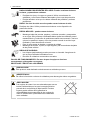 7
7
-
 8
8
-
 9
9
-
 10
10
-
 11
11
-
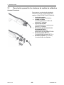 12
12
-
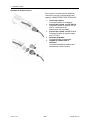 13
13
-
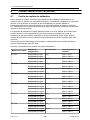 14
14
-
 15
15
-
 16
16
-
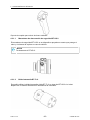 17
17
-
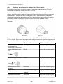 18
18
-
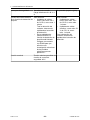 19
19
-
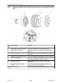 20
20
-
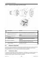 21
21
-
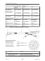 22
22
-
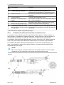 23
23
-
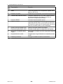 24
24
-
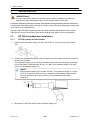 25
25
-
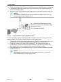 26
26
-
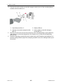 27
27
-
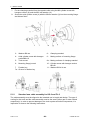 28
28
-
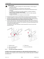 29
29
-
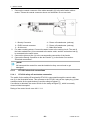 30
30
-
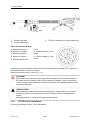 31
31
-
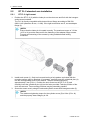 32
32
-
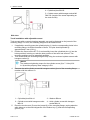 33
33
-
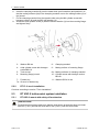 34
34
-
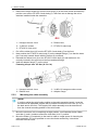 35
35
-
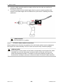 36
36
-
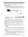 37
37
-
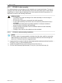 38
38
-
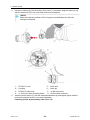 39
39
-
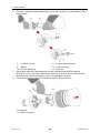 40
40
-
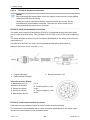 41
41
-
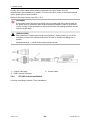 42
42
-
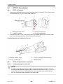 43
43
-
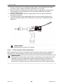 44
44
-
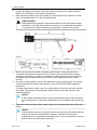 45
45
-
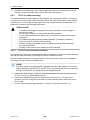 46
46
-
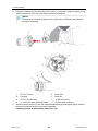 47
47
-
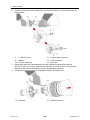 48
48
-
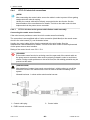 49
49
-
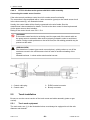 50
50
-
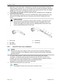 51
51
-
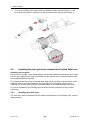 52
52
-
 53
53
-
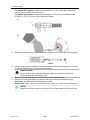 54
54
-
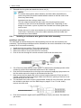 55
55
-
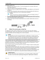 56
56
-
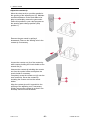 57
57
-
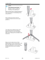 58
58
-
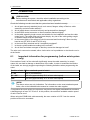 59
59
-
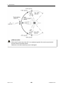 60
60
-
 61
61
-
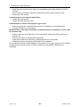 62
62
-
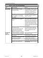 63
63
-
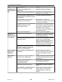 64
64
-
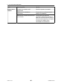 65
65
-
 66
66
-
 67
67
-
 68
68


ESAB RT Robo Welding Torch System Manual de usuario
- Categoría
- Robótica
- Tipo
- Manual de usuario
en otros idiomas
Artículos relacionados
-
ESAB RT Robo Welding Torch System Manual de usuario
-
-
-
ESAB Robust Feed Pulse Manual de usuario
-
-
-
ESAB Origo™ Feed 4804 Manual de usuario
-
ESAB PSF 520w Manual de usuario
-
ESAB MXL 341 Manual de usuario
-
ESAB MXL 201 MXL 271 MXL 341 MXL 411W MXL 511W Manual de usuario