ESAB RT Robo Welding Torch System Manual de usuario
- Tipo
- Manual de usuario

Instrucciones de uso
0463 373 101 XL 20181227
RT Robo Welding Torch System
RTKS-2, RTFL-2, KSC-2, FLC-2, RT42, RT52,
RT62, RT72, RT82, RT42-NG, RT82WNG


TABLA DE CONTENIDO
0463 373 101 © ESAB AB 2018
1
SEGURIDAD................................................................................................ 5
1.1 Significado de los símbolos.................................................................. 5
1.2 Precauciones de seguridad................................................................... 5
2
GARANTÍA................................................................................................... 9
2.1 Condiciones de uso previsto ................................................................ 9
3
INTRODUCCIÓN.......................................................................................... 11
3.1 Descripción general de los sistemas de soplete de soldadura ......... 12
4
CARACTERÍSTICAS TÉCNICAS................................................................ 14
4.1 Cuello de soplete de soldadura ............................................................ 14
4.2 Tensión nominal ..................................................................................... 15
4.2.1 Límites del circuito de enfriamiento...................................................... 16
4.3 Soporte del soplete ................................................................................ 16
4.3.1 Soporte de soplete para el sistema RT estándar ................................. 16
4.3.1.1 Mecanismo de apagado de seguridad RT KS-2................................ 17
4.3.1.2 Brida intermedia RT FL-2 .................................................................. 17
4.3.2 Montajes de soplete para el sistema de muñeca hueca ...................... 18
4.3.2.1 Soporte de soplete RT KSC-2 G/W con mecanismo de apagado de
seguridad...........................................................................................
19
4.3.2.2 Soporte de soplete rígido RT FLC-2 G/W ......................................... 20
4.4 Bridas del adaptador.............................................................................. 21
4.5 Conjuntos de cable ................................................................................ 21
4.5.1 Conjuntos de cables para el sistema RT estándar............................... 21
4.5.2 Conjuntos de cables para sistemas de muñeca hueca........................ 22
5
INSTALLATION............................................................................................ 24
5.1 RTKS-2 standard arm installation........................................................ 24
5.1.1 RTKS-2 safety-off mechanism............................................................. 24
5.1.1.1 Torch installation with adjustable mount............................................ 25
5.1.2 Standard arm cable assembly for KS-2 and FL-2 ................................ 27
5.1.3 RTKS-2 wire feeder connection........................................................... 28
5.1.4 RTKS-2 electrical connections ............................................................ 29
5.1.4.1 RTKS-2 safety-off mechanism connection ....................................... 29
5.1.5 RTKS-2 Torch installation .................................................................... 30
5.2 RTFL-2 standard arm installation ........................................................ 31
5.2.1 RTFL-2 rigid mount.............................................................................. 31
5.2.2 RTFL-2 torch installation ..................................................................... 33
5.3 RTKSC-2 hollow wrist system installation.......................................... 33
5.3.1 RTKSC-2 mount with safety off mechanism........................................ 33
5.3.2 Mounting the cable assembly............................................................... 34
5.3.2.1 RTKSC-2 feeder cabinet connections .............................................. 35
5.3.3 RTKSC-2 cable assembly ................................................................... 37
5.3.3.1 RTKSC-2 cable assembly installation .............................................. 37

TABLA DE CONTENIDO
0463 373 101 © ESAB AB 2018
5.3.3.2 RTKSC-2 electrical connections....................................................... 40
5.3.4 RTKSC-2 torch installation .................................................................. 41
5.4 RTFLC-2 installation.............................................................................. 42
5.4.1 RTFLC-2 mount................................................................................... 42
5.4.2 RTFLC-2 wire feeder connection......................................................... 42
5.4.2.1 Feeding through the robot arm.......................................................... 42
5.4.2.2 RTFLC-2 feeder cabinet connections............................................... 43
5.4.3 RTFLC-2 cable assembly .................................................................... 45
5.4.3.1 RTFLC-2 cable assembly installation ............................................... 45
5.4.4 RTFLC-2 electrical connections .......................................................... 48
5.4.4.1 RTFLC-2 hollow wrist system with Infiniturn cable assembly........... 48
5.4.4.2 RTFLC-2 hollow wrist system with Helix cable assembly................. 49
5.5 Torch installation.................................................................................... 49
5.5.1 Torch neck equipment .......................................................................... 49
5.5.2 Aristo RT torch neck installation........................................................... 50
5.6 Installing the wire guide for standard and hollow Wrist arm ............. 51
5.6.1 Installing the neck liner......................................................................... 51
5.6.2 Installing a split wire guide in the cable assembly................................ 52
5.6.3 Installing a continuous wire guide in the cable assembly..................... 54
5.7 Adjust the narrow gap contact tip ........................................................ 55
6
OPERATION ................................................................................................ 58
6.1 Important information for programming (hollow wrist system only) 58
7
SERVICIO Y MANTENIMIENTO.................................................................. 60
7.1 Verificaciones y acciones obligatorias ................................................ 60
8
SOLUCIÓN DE PROBLEMAS .................................................................... 62
9
PEDIDOS DE REPUESTOS ........................................................................ 65
Se reserva el derecho de modificar las especificaciones sin previo aviso.

1 SEGURIDAD
0463 373 101
- 5 -
© ESAB AB 2018
1 SEGURIDAD
1.1 Significado de los símbolos
Según se utilizan en este manual: Significa ¡Atención! ¡Tenga cuidado!
¡PELIGRO!
Significa peligros inmediatos que, si no se evitan, causarán lesiones
personales graves o incluso la pérdida de la vida.
¡ADVERTENCIA!
Significa peligros potenciales que podrían causar lesiones personales o la
pérdida de la vida.
¡PRECAUCIÓN!
Significa peligros que podrían causar lesiones personales menores.
¡ADVERTENCIA!
Antes de utilizar el equipo, lea y comprenda el manual
de instrucciones y siga todas las etiquetas, las prácticas
de seguridad del empleador y las hojas de datos de
seguridad (SDS, por sus siglas en inglés).
1.2 Precauciones de seguridad
Los usuarios del equipo ESAB tienen la absoluta responsabilidad de garantizar que toda
persona que trabaje con el equipo o cerca de este respete todas las precauciones de
seguridad correspondientes. Las precauciones de seguridad deben cumplir con los
requisitos que se aplican a este tipo de equipo. Se deben tener en cuenta las siguientes
recomendaciones, además de las regulaciones estándar que se aplican en el lugar de
trabajo.
Todo trabajo debe ser realizado por personal capacitado que esté familiarizado con la
operación del equipo. La operación incorrecta del equipo podría generar situaciones
peligrosas que pueden ocasionar lesiones al operador y daños al equipo.
1. Toda persona que utilice el equipo debe estar familiarizada con:
○ su operación
○ la ubicación de las paradas de emergencia
○ su función
○ las precauciones de seguridad correspondientes
○ las operaciones de soldadura y corte u otras operaciones aplicables del equipo
2. El operador debe garantizar que:
○ no haya ninguna persona no autorizada en el área de trabajo cuando se
arranque el equipo
○ no haya ninguna persona sin protección cuando se golpee el arco o se inicie el
trabajo con el equipo
3. El lugar de trabajo debe:
○ ser adecuado para la operación
○ estar libre de corrientes de aire

1 SEGURIDAD
0463 373 101
- 6 -
© ESAB AB 2018
4. Equipo de seguridad personal:
○ Use siempre el equipo de seguridad personal recomendado, como gafas
protectoras, prendas ignífugas y guantes de seguridad
○ No use accesorios que suelen quedar holgados, como bufandas, pulseras,
anillos, etc. que podrían quedar atrapados u ocasionar quemaduras
5. Precauciones generales:
○ Asegúrese de que el cable de retorno esté bien conectado
○ Los trabajos en el equipo de alta tensión solo pueden ser realizados por un
electricista calificado
○ El equipo extintor de incendios adecuado debe estar muy cerca y claramente
marcado
○ No se debe realizar la lubricación ni el mantenimiento del equipo durante la
operación
¡ADVERTENCIA!
El corte y la soldadura por arco pueden ser perjudiciales para usted y otras
personas. Tome precauciones al soldar y cortar.
La DESCARGA ELÉCTRICA puede ser mortal
• Instale y conecte a tierra la unidad según el manual de instrucciones.
• No toque las piezas eléctricas con tensión o electrodos con la piel, con
guantes húmedos ni con la ropa húmeda.
• Utilice elementos aislantes.
• Asegúrese de que la posición para trabajar sea segura
Los CAMPOS ELÉCTRICOS Y MAGNÉTICOS pueden ser peligrosos para
su salud
• Los soldadores que usan marcapasos deben consultar a su médico antes
de soldar. Los EMF podrían interferir con algunos marcapasos.
• La exposición a EMF podría tener otras consecuencias para la salud que
son desconocidas.
• Los soldadores deben utilizar los siguientes procedimientos para minimizar
la exposición a EMF:
○ Pase el electrodo y los cables de trabajo juntos a un mismo lado del
cuerpo. Sujételos con cinta si es posible. No coloque el cuerpo entre
los cables de trabajo y del soplete. Nunca debe enrollarse el cable
de trabajo o soplete por el cuerpo. Mantenga los cables y la fuente
de alimentación de soldadura lo más lejos posible del cuerpo.
○ Conecte el cable de trabajo a la pieza de trabajo lo más cerca
posible al área que se soldará.
Los HUMOS Y GASES pueden ser peligrosos para su salud
• Protéjase la cabeza de los humos.
• Utilice ventilación, extracción en el arco o ambas para expulsar los humos
y gases de la zona de respiración y del área en general.
Los ARCOS ELÉCTRICOS pueden causar lesiones en los ojos y
quemaduras en la piel
• Protéjase los ojos y el cuerpo. Utilice la pantalla para soldar y las lentes
filtradoras correctas y use vestimenta protectora.
• Proteja a las personas que se encuentran en el lugar utilizando pantallas o
cortinas adecuadas.

1 SEGURIDAD
0463 373 101
- 7 -
© ESAB AB 2018
RUIDO: el ruido excesivo puede dañar la audición
Protéjase los oídos. Utilice orejeras o alguna otra protección para los oídos.
Las PIEZAS MÓVILES pueden causar lesiones
• Mantenga todos los paneles, las puertas y las cubiertas cerrados y bien
seguros en su lugar. Si es necesario, solo personal calificado puede retirar
cubiertas para realizar mantenimiento o solucionar problemas. Vuelva a
instalar los paneles o las cubiertas y cierre las puertas cuando haya
finalizado el servicio y antes de arrancar el motor.
• Detenga el motor antes de instalar o conectar la unidad.
• Mantenga las manos, el cabello, la ropa holgada y las herramientas
alejadas de las piezas móviles.
PELIGRO DE INCENDIO
• Las chispas (salpicaduras) pueden causar incendios. Asegúrese de que
no haya materiales inflamables cerca.
• Evite que se produzcan en contenedores cerrados.
FUNCIONAMIENTO INCORRECTO: llame al servicio de asistencia de expertos en
caso de falla.
¡PROTÉJASE Y PROTEJA A LAS OTRAS PERSONAS!
¡PRECAUCIÓN!
Este producto está destinado únicamente a la soldadura por arco.
¡ADVERTENCIA!
No utilice la fuente de alimentación para descongelar las tuberías congeladas.
¡PRECAUCIÓN!
Los equipos clase A no se pueden utilizar en
residencias donde la energía eléctrica es suministrada
por el sistema público de baja tensión. Podrían surgir
algunas dificultades al garantizar la compatibilidad
electromagnética de los equipos clase A en esas
ubicaciones debido a las perturbaciones conducidas y
radiadas.

1 SEGURIDAD
0463 373 101
- 8 -
© ESAB AB 2018
¡NOTA!
¡Deseche los equipos electrónicos en la instalación
de reciclaje!
En cumplimiento con la normativa europea 2012/19/EC
sobre cómo desechar los equipos eléctricos y
electrónicos y su implementación de acuerdo con la
legislación nacional, los equipos eléctricos y/o
electrónicos que han alcanzado el fin de su vida útil se
deben desechar en una instalación de reciclaje.
Como la persona responsable del equipo, es su
responsabilidad obtener información sobre las
estaciones de recolección aprobadas.
Para obtener más información, comuníquese con el
distribuidor de ESAB más cercano.
ESAB cuenta con una gran variedad de accesorios de soldadura y equipos de
protección personal a la venta. Para obtener información relacionada con pedidos,
comuníquese con su distribuidor local de ESAB o visite nuestro sitio web.

2 GARANTÍA
0463 373 101
- 9 -
© ESAB AB 2018
2 GARANTÍA
Antes de la entrega, nuestros productos se revisan cuidadosamente. ESAB verifica que
cada producto no tenga defectos de material y mano de obra en el momento de la entrega, y
que funcione de acuerdo con su uso previsto.
ESAB ofrece garantía por defectos de material y mano de obra de acuerdo con las
exigencias legales. Los productos de consumo están exentos de esta garantía.
La garantía no cubre daños o defectos funcionales resultantes de lo siguiente:
• sobrecarga, mal uso o uso que se aleje del uso previsto del producto;
• colisiones o accidentes;
• incumplimiento de las indicaciones consignadas en estas instrucciones de
funcionamiento;
• instalación o montaje incorrectos;
• mantenimiento insuficiente;
• modificar la condición original del producto;
• influencias químicas;
• uso y desgaste normales.
ESAB no asume otra responsabilidad aparte de la sustitución o reparación de las piezas
defectuosas.
2.1 Condiciones de uso previsto
1. El producto está diseñado para uso industrial y comercial y solo debe ser utilizado por
personal capacitado. El fabricante no se hace responsable de ningún daño o
accidente ocasionado por un uso inadecuado.
2. El sistema de soldadura robótica Aristo® RT se diseña y produce con tecnología de
avanzada y es seguro y confiable cuando está en funcionamiento si lo manipula,
instala y mantiene personal capacitado. Se deben seguir las instrucciones de
instalación, operación y mantenimiento que se describen en este documento.
3. El sistema de soldadura robótica Aristo® RT puede ser instalado, operado y reparado
solo por personal capacitado. Se deben seguir las normas de instalación, operación y
mantenimiento que se detallan en este manual.
4. El sistema de soldadura robótica Aristo® RT se puede utilizar únicamente para fines
previstos por el fabricante dentro del marco de sus datos técnicos y con sistemas de
manejo automatizados. Se debe seleccionar el tipo de soplete para que se adapte a
la tarea de soldadura.
5. El sistema de soldadura robótica Aristo® RT se diseñó para usarse como un sistema
completo. No se permite la incorporación de componentes de otros fabricantes en el
sistema.
6. Los modelos RT KS-2 y RT KSC-2 solo se pueden utilizar como mecanismos de
parada de emergencia dentro de sus especificaciones técnicas y en combinación con
un conjunto de cable de brazo estándar RT (KS-2), Infiniturn o Helix (KSC-2), brida
del adaptador ESAB, que incluye montajes del soplete RT (KS-2) y un soplete de
soldar Aristo RT.
7. No se debe agregar aceite ni líquido antisalpicaduras al gas de soplado. ESAB no
garantiza la resistencia química a esas sustancias. ESAB recomienda utilizar la
unidad de pulverización ESAB para aplicar la cantidad mínima de líquido
antisalpicaduras al soplete y, por lo tanto, proteger el medioambiente.

2 GARANTÍA
0463 373 101
- 10 -
© ESAB AB 2018
8. El producto se debe mantener seco y protegido de la humedad durante su transporte,
almacenamiento o uso.
9. El sistema está diseñado para un rango de temperaturas ambientales de 5°C a 40°C
(41°F a 104°F). En caso de que se superen estos límites, es necesario realizar una
acción específica. En caso de riesgo de congelación, utilice un refrigerante adecuado.

3 INTRODUCCIÓN
0463 373 101
- 11 -
© ESAB AB 2018
3 INTRODUCCIÓN
Los sistemas de soplete de soldadura RT se desarrollan para la soldadura MIG/MAG
completamente automática mediante robots. Los sistemas constan de una gran variedad de
cuellos de sopletes Aristo RT diseñados para uso robótico, montaje de sopletes, conjuntos
de cables optimizados para uso robótico y funciones de apagado de seguridad para evitar
que el sistema sufra daños en caso de colisión.
El sistema de soldadura estándar RT ofrece protección contra colisiones mediante el uso de
RT KS-2, que es una funcionalidad mecánica de apagado de seguridad accionada por
resorte. De manera opcional, esto puede reemplazarse por RT FL-2 para aprovechar la
función de detección de colisión del sistema de control del robot. El sistema estándar de
soldadura RT se puede utilizar con una variedad de tipos de conjunto de cables.
Los montajes de soldadura RT KSC-2 y RT FLC-2 con cables Infiniturn o Helix están
diseñados para usarse en sistemas de soldadura robótica de muñeca hueca, diseñados
para aplicaciones avanzadas de soldadura. El mecanismo de apagado de seguridad en el
montaje de sopletes RT KSC-2 permite deflexión elástica grande del soplete en caso de
colisión. Los conjuntos de cable Infiniturn y Helix son fáciles de instalar, lo que proporciona
un sistema altamente confiable con capacidades de maniobra precisas.
En combinación con los bien establecidos sopletes de soldadura robótica Aristo RT, estos
componentes crean un sistema altamente confiable y de larga duración que solo necesita un
mínimo de mantenimiento.
El manual de instrucciones se incluye en la entrega de montajes para soplete y conjuntos de
cable.
Los números de pedido de ESAB, los accesorios disponibles, las piezas de repuesto y
las piezas de desgaste se encuentran en la lista de piezas de repuesto.

3 INTRODUCCIÓN
0463 373 101
- 12 -
© ESAB AB 2018
3.1 Descripción general de los sistemas de soplete de soldadura
Sistema RT estándar
Para obtener una descripción detallada,
consulte la sección correspondiente del
capítulo DATOS TÉCNICOS:
1. Cuello del soplete
Consulte "Soldadura de soplete".
2. Conjunto de cables
Consulte "Conjuntos de cables para
sistema RT estándar".
3. Soporte del soplete
Consulte "Montajes de soplete para
el sistema RT estándar".
4. Mecanismo de apagado de
seguridad RT KS-2
Consulte "Mecanismo de apagado
de seguridad RT KS-2".
5. Brida intermedia RT FL-2
Consulte "Brida intermedia RT
FL-2".
6. Brida del adaptador (si es
necesario)
Consulte "Bridas del adaptador".

3 INTRODUCCIÓN
0463 373 101
- 13 -
© ESAB AB 2018
Sistema de muñeca hueca
Para obtener una descripción detallada,
consulte la sección correspondiente del
capítulo DATOS TÉCNICOS:
1. Cuello del soplete
Consulte "Soldadura de soplete".
2. Soporte de soplete RT KSC-2
Consulte "Soporte de soplete RT
KSC-2 con mecanismo de apagado
de seguridad".
3. Soporte de soplete RT FLC-2
Consulte "Soporte de soplete rígido
RT FLC-2".
4. Brida del adaptador
Consulte "Bridas del adaptador".
5. Conjunto de cable Helix o
Infiniturn
Consulte "Conjuntos de cables para
sistemas de muñeca hueca".

4 CARACTERÍSTICAS TÉCNICAS
0463 373 101
- 14 -
© ESAB AB 2018
4 CARACTERÍSTICAS TÉCNICAS
4.1 Cuello de soplete de soldadura
Elija el modelo de soplete según la aplicación de soldadura. Se deben tener en cuenta el
ciclo de trabajo y la capacidad necesarios, el método de enfriamiento y el diámetro del cable.
Si hay mayores requisitos, por ejemplo, causados por piezas de trabajo precalentadas o alta
reflexión térmica en las esquinas, tenga en cuenta esto seleccionando un soplete de
soldadura con la reserva de potencia nominal adecuada.
Los sopletes de soldadura RT están diseñados para su uso con fuentes de energía de
soldadura en conformidad con CE para los procesos de soldadura de gas de metal inerte
(MIG), soldadura de gas metálico activo (MAG) y soldadura de gas MIG con cables
redondos comerciales. No use el soplete para otros procesos.
Para la soldadura por arco de impulsos de acero o aluminio, se debe utilizar un soplete
enfriado por agua RT 82W.
Consulte los modelos de sopletes disponibles a continuación.
Modelo de soplete
Método de
enfriamiento
Gas de protección Especificación
RT42G Enfriado por gas CO
2
420A/60%
Enfriado por gas 300A/100%
Enfriado por gas Mezcla 350A/60%
Enfriado por gas 250A/100%
RT42W Enfriado por agua CO
2
420A/60%
Enfriado por agua 420A/100%
Enfriado por agua Mezcla 350A/60%
Enfriado por agua 350A/100%
RT52G Enfriado por gas CO
2
420A/60%
Enfriado por gas 300A/100%
Enfriado por gas Mezcla 350A/60%
Enfriado por gas 250A/100%
RT52W Enfriado por agua CO
2
470A/60%
Enfriado por agua 470A/100%
Enfriado por agua Mezcla 400A/60%
Enfriado por agua 400A/100%
RT62G Enfriado por gas CO
2
500A/60%
Enfriado por gas 340A/100%
Enfriado por gas Mezcla 420A/60%
Enfriado por gas 290A/100%
RT62W Enfriado por agua CO
2
530A/60%
Enfriado por agua 530A/100%
Enfriado por agua Mezcla 450A/60%
Enfriado por agua 450A/100%

4 CARACTERÍSTICAS TÉCNICAS
0463 373 101
- 15 -
© ESAB AB 2018
Modelo de soplete
Método de
enfriamiento
Gas de protección Especificación
RT72G Enfriado por gas CO
2
480A /60%
Enfriado por gas 320A/100%
Enfriado por gas Mezcla 400A/60%
Enfriado por gas 270A/100%
RT72W Enfriado por agua CO
2
480A/60%
Enfriado por agua 430A/100%
Enfriado por agua Mezcla 480A/60%
Enfriado por agua 430A/100%
RT82W Enfriado por agua CO
2
600A/60%
Enfriado por agua 600A/100%
Enfriado por agua Mezcla 550A/60%
Enfriado por agua 550A/100%
Los valores de la clasificación de soplete y del ciclo de trabajo son válidos durante un ciclo
de 10 minutos.
Los datos técnicos son válidos para una aplicación estandarizada que utiliza las piezas de
desgaste y repuesto estándar. La clasificación del soplete se reduce cuando se utiliza el
modo de transferencia de metal por arco de impulsos.
Rangos de temperatura Almacenamiento: -15-50°C (5-122°F)
Funcionamiento: 5–40°C (41–104°F)
Gas de soplado Manguera de gas separada de un máximo de
10 bares
Peso total (cuello de soplete, mecanismo de
apagado de seguridad, montaje con soplete
y conjunto de cable de 1m)
Aproximadamente 5kg
4.2 Tensión nominal
Voltaje/amperaje máximo permitido
Sistema completo de soplete de soldadura 141V (valor máximo para soldadura)
Circuito de control de apagado de seguridad
RT KS-2
Botón pulsador RT KS-2
24V/1A
48V/0,1A
Circuito de control de apagado de seguridad
RT KSC-2
48 V
Uso de la funcionalidad de detección de
boquillas con un conjunto de cable estándar
50V/5A
(Carga máxima permitida 1 minuto a la
corriente nominal)
Uso de la funcionalidad de detección de la
boquilla con conjuntos de cable Helix o
Infiniturn
50V/5A
(Carga máxima permitida 1 minuto a la
corriente nominal)
Las clasificaciones indicadas se refieren a un caso de uso estandarizado.

4 CARACTERÍSTICAS TÉCNICAS
0463 373 101
- 16 -
© ESAB AB 2018
Para conocer las clasificaciones de montaje de cables, consulte la sección "Conjuntos de
cables".
4.2.1 Límites del circuito de enfriamiento
Válido solo para la versión de enfriado por agua.
Caudal mínimo de agua: 1,0l/min (1,1 cuartos de galón/min)
Presión mínima del agua: 2,5bar (36,3PSI)
Presión máxima del agua: 3,5bar (50.8PSI)
Temperatura de entrada: Máximo 40°C (104°F)
Temperatura de retorno: Máximo 60 °C (140 °F)
Capacidad de enfriamiento: Mínimo 1000W, según la aplicación
¡PRECAUCIÓN!
Las temperaturas de retorno superiores a 60°C (140 °F) pueden causar daños o
destruir el conjunto de cable.
4.3 Soporte del soplete
El tipo de soporte de soplete requerido depende del diseño del sistema de soplete de
soldadura RT y de la elección de los dispositivos de apagado de seguridad; consulte la
sección “Descripción general de los sistemas de soplete de soldadura".
Componente Peso aproximado
Soporte de soplete (para el sistema
estándar)
0,43 kg
Mecanismo de apagado de seguridad RT
KS-2 (para el sistema estándar)
0,85 kg
Brida intermedia RT FL-2 (para sistema
estándar)
0,35 kg
Soporte de soplete RT KSC-2 (para el
sistema de muñeca hueca)
1,90 kg
Soporte de soplete rígido RT FLC-2 (para
sistema de muñeca hueca)
1,22 kg
Soplete de soldadura robótica 0,66 kg
4.3.1 Soporte de soplete para el sistema RT estándar
Para los sistemas estándar de RT, el soporte de soplete está instalado en el mecanismo de
apagado de seguridad de RT KS-2 (alternativamente en la brida intermedia de RT FL-2),
sujetando el conjunto de cable y el cuello de soplete conectado.
Seleccione el soporte de soplete de acuerdo con el tipo de soplete y su geometría. Se
pueden utilizar varios tipos de montaje. Consulte la lista de piezas de repuesto para ver los
montajes de soplete disponibles para el sistema RT estándar.

4 CARACTERÍSTICAS TÉCNICAS
0463 373 101
- 17 -
© ESAB AB 2018
Soporte de soplete para robots de brazo estándar
4.3.1.1 Mecanismo de apagado de seguridad RT KS-2
El mecanismo de seguridad RT KS-2 es un dispositivo con soporte de resortes que protege
al robot y al sistema de soplete en caso de una colisión.
¡NOTA!
No desmonte el RT KS-2.
4.3.1.2 Brida intermedia RT FL-2
La brida intermedia rígida RT FL-2 se puede utilizar en lugar del RT KS-2 si el robot tiene
un sistema de detección de colisión electrónica.

4 CARACTERÍSTICAS TÉCNICAS
0463 373 101
- 18 -
© ESAB AB 2018
4.3.2 Montajes de soplete para el sistema de muñeca hueca
En el sistema de muñeca hueca, los cuellos de soplete de soldadura Aristo RT están
conectados al soporte de soplete KSC-2 o FLC-2.
El soporte de soplete RT KSC-2 permite una deflexión elástica del soplete en caso de una
colisión. Al mismo tiempo, se abre un contacto eléctrico, que indica al control del robot que
se detenga. Después de restablecer el error, se alcanzará la geometría inicial y el punto
central de herramientas (TCP) del soplete con alta precisión. El sistema funciona solo
mecánicamente y por resorte.
El soporte de soplete RT FLC-2 no tiene una función de apagado de seguridad incorporada.
Para los sistemas de muñeca hueca se recomienda RT KSC-2 G/W (alternativamente, RT
FLC-2 G/W). Este soporte de soplete se puede utilizar con sopletes enfriados por gas y
sopletes enfriados por agua de la serie Aristo RT.
RTKSC-2 G/W RTFLC-2 G/W
Principio funcional del
mecanismo de apagado de
seguridad
Mecánico No aplicable (soporte rígido)
Fuerza de liberación axial
(FZ)
650N No aplicable (soporte rígido)
Liberar la torsión en el eje
transversal (Mx)
24 Nm No aplicable (soporte rígido)
Reiniciar después de liberar Automatic No aplicable (soporte rígido)
Repetibilidad Lateral ± 0,1mm en el TCP
de un soplete estándar Aristo
RT
No aplicable (soporte rígido)
Deflexión máxima Aprox. ± 8° No aplicable (soporte rígido)
Interruptor de seguridad Normalmente cerrado
Carga eléctrica máxima
48V/1A
No aplicable (soporte rígido)

4 CARACTERÍSTICAS TÉCNICAS
0463 373 101
- 19 -
© ESAB AB 2018
Circuito de control eléctrico
para la función de detección
de boquillas
Tensión nominal:
• Para conjuntos de cable
Helix: máx. 50V
CC/5A, máx. 1 minuto
Después de detectar el
contacto, desconecte
rápidamente el voltaje
de detección.
• Para los conjuntos de
cable Infiniturn, la
función de detección de
boquillas tiene una
funcionalidad limitada.
Comuníquese con
ESAB para obtener una
investigación detallada
de posibles soluciones
en su aplicación.
Tensión nominal:
• Para conjuntos de cable
Helix: máx 50V CC/5A,
máx. 1 minuto
• Para conjuntos de cable
Infiniturn: máx. 50V
CC/1 A, máx. 1 minuto
Después de detectar el
contacto, desconecte
rápidamente el voltaje de
detección.
Tensión nominal Voltaje máximo permitido
para el circuito de control de
apagado de seguridad: 48V.
4.3.2.1 Soporte de soplete RT KSC-2 G/W con mecanismo de apagado de seguridad
Item Descripción Función
1 Soporte de cuello de soplete Interfaz de soplete Aristo RT
2 Cubierta RT KSC-2 Conjunto con interfaces de cable y soplete

4 CARACTERÍSTICAS TÉCNICAS
0463 373 101
- 20 -
© ESAB AB 2018
Item Descripción Función
3 Sello de caucho Protección para el mecanismo de apagado de
seguridad
4 Cuerpo principal RT KSC-2 Permite la deflexión mecánica durante una colisión
5 Brida del adaptador Interfaz aislante para la muñeca del robot (debe
encajar en el robot específico)
6 Pasador guía Para una alineación precisa con la brida del
adaptador
7 Conector para cable de control Conexión eléctrica para la señal de colisión y la
función de detección de boquillas
8 Microinterruptor Sensor de detección de colisión
4.3.2.2 Soporte de soplete rígido RT FLC-2 G/W
Item Descripción Función
1 Soporte de cuello de soplete Interfaz de soplete Aristo RT
2 Cubierta RT FLC-2 Conjunto con interfaces de cable y soplete
3 Cuerpo principal RT FLC-2 Permite la deflexión mecánica durante una colisión
4 Pasador guía Para una alineación precisa con la brida del
adaptador
5 Brida del adaptador Interfaz aislante para la muñeca del robot (debe
encajar en el robot específico)
6 Conector para cable de control
(3 polos)
Conexión eléctrica para la función de detección de
boquillas (si corresponde)

4 CARACTERÍSTICAS TÉCNICAS
0463 373 101
- 21 -
© ESAB AB 2018
4.4 Bridas del adaptador
Elija la brida del adaptador necesaria para la instalación en el brazo del robot según el tipo
de robot. Se encuentran disponibles las bridas del adaptador para todos los sistemas de
muñeca estándar o hueca, consulte la lista de piezas de repuesto.
4.5 Conjuntos de cable
La conexión al alimentador de alambre es realizada por el conjunto de cables, las versiones
disponibles dependen principalmente del diseño del sistema y los medios de enfriamiento
(gas o agua), consulte la lista de piezas de repuesto.
Las clasificaciones son válidas para longitudes de cable de 1 a 5m.
Conjunto de cables
estándar
Infiniturn Helix
Clasificación (ciclo de
10 min.)
Enfriado por gas (gas
mezclado)
Máx. 500A/60% de
ciclo operación
Máx. 350A/100% de
ciclo operación
Máx. 400A/60% de
ciclo operación
Máx. 320A/100% de
ciclo operación
Máx. 400A/60% de
ciclo operación
Máx. 320A/100% de
ciclo operación
Clasificación (ciclo de
10 min.)
Enfriado por agua
Máx. 600A/100% de
ciclo operación
Máx. 550A/100% de
ciclo operación
Máx. 550A/100% de
ciclo operación
Rango de rotación Capacidad de
rotación limitada
Gira sin parar ± 270° desde la
posición neutral
Peso
Enfriado por gas
1,2 m de largo:
2,35 kg
1,0m de largo:
2,0 kg
1,0m de largo:
2,0 kg
Peso
Enfriado por agua
1,2 m de largo:
2,35 kg
1,0m de largo:
2,0 kg
1,0m de largo:
2,0 kg
4.5.1 Conjuntos de cables para el sistema RT estándar

4 CARACTERÍSTICAS TÉCNICAS
0463 373 101
- 22 -
© ESAB AB 2018
Pasadores del conector Burndy
A. Boquilla de gas de
detección de contacto
C. Sensor de colisión
D. Sensor de colisión
E. Avance lento
F. 0V
G. + Voltaje del motor
H. - Voltaje del motor
Item Descripción Función
1 Brida de soporte del cuello Interfaz del soplete
2 Cubierta protectora Protege el conjunto de cable de daños
3 Conector Burndy, 12 polos Conexión eléctrica entre el apagado de seguridad y
el alimentador de alambre
4 Cable de control Para KS-2 (apagado de seguridad y botón pulsador)
5 Conector EURO Conexión del alimentador de alambre
6 Manguera de soplado (tapa
negra)
Para limpiar el soplete con aire comprimido después
del ciclo de limpieza
7 Entrada de agua (tapa azul)
Admisión de agua para el enfriamiento con soplete
1)
8 Retorno de agua (tapa roja)
Retorno de agua del agua caliente del soplete
1)
9 Enchufe del cable de control
para el mecanismo de apagado
de seguridad
Conexión eléctrica con RT KS-2 para la señal de
apagado de seguridad y la función de detección de
boquillas
1)
Solo sistemas de soplete enfriados por agua
4.5.2 Conjuntos de cables para sistemas de muñeca hueca
El conjunto de cable Infiniturn permite una rotación infinita del soplete en ambas direcciones.
Al mismo tiempo, se transfieren el líquido de enfriamiento, el gas de protección, el aire de
soplado, la potencia de soldadura y la señal del mecanismo de apagado de seguridad.
El conjunto de cable Helix está diseñado para un rango de rotación de ±270° desde la
posición neutral. Se puede utilizar para tareas de soldadura que no requieren una rotación
infinita.
Los conjuntos de cable Infiniturn están disponibles en versiones de enfriamiento por gas y
por agua. Los conjuntos de cable Helix se pueden utilizar universalmente para aplicaciones
de enfriamiento por gas o por agua.
¡NOTA!
No conecte un conjunto de cable Helix que funcione con un soplete enfriado por
gas en un sistema de refrigeración por agua.

4 CARACTERÍSTICAS TÉCNICAS
0463 373 101
- 23 -
© ESAB AB 2018
Item Descripción Función
1 Brida Soporte de soplete RT KSC-2/interfaz RT FLC-2
2 Pasador guía Asegura la correcta orientación del acoplamiento
3 Enchufe del cable de control Conexión eléctrica a RT KSC-2 para la señal de
apagado de seguridad y la función de detección de
boquillas (si corresponde)
4 Conector EURO Conexión del alimentador de alambre
5 Cable de control Conexión eléctrica para la señal de apagado de
seguridad (de RT KSC-2) y la función de detección
de boquillas (el sensor de boquilla es estándar para
Helix, no para Infiniturn)
6 Retorno de agua (tapa roja) Retorno de agua del agua caliente del soplete
7 Entrada de agua (tapa azul) Admisión de agua para el enfriamiento con soplete
8 Manguera de soplado (tapa
negra)
Para limpiar el soplete con aire comprimido después
de soldar
9 Acoplamiento de medios Acoplamiento giratorio continuo con transferencia
de medios
10 Cubierta protectora Protege el conjunto de cable de daños

5 INSTALLATION
0463 373 101
- 24 -
© ESAB AB 2018
5 INSTALLATION
¡ADVERTENCIA!
For your own safety, make sure that the robot is either in standby or power-less
state before doing maintenance work in the moving radius of the robot.
Follow the assembly instructions exactly. Pay attention during assembly that the cables are
not damaged. Damaged cables can lead to a short circuit, which may damage the electronics
of the robot or the welding torch.
Use only original ESAB components that have been specially developed for this purpose.
Only then the correct functioning of the whole welding torch system can be guaranteed.
5.1 RTKS-2 standard arm installation
5.1.1 RTKS-2 safety-off mechanism
1. Dismount the insulation flange (10) from the RTKS-2 (11) by removing the screws
(12).
2. Position the insulation flange (10) with the index pin on the robot arm and fix it with the
screws (20) included.
The insulation flange (10) is directly compatible with robots with tool flange according
to DIN ISO 9409-1-A40 (diameter 40mm, 4×M6). If the insulation flange (10) does
not fit, use an adapter flange (21).
¡NOTA!
Ensure that the index pin is located correctly. The maximum torque of 1.2Nm
(10.5in.lb) must be observed for the fastening of the adapter flange screws.
Prevent self-loosening of the screws by using suitable thread locking
measures.
3. Mount the RTKS-2 the back on the insulation flange (10).

5 INSTALLATION
0463 373 101
- 25 -
© ESAB AB 2018
4. Position the mount on the RTKS-2 and carefully insert the cylindrical pins (14) into the
holes provided. Take the position of the torch into account. Two mounting positions
may be potentially possible.
5. Screw the mount evenly using the enclosed cylinder screws with hexagon socket (12).
¡NOTA!
The maximum tightening torque for the cylinder screw (5) is 6Nm (53in.lb)
and the property class category is 8.8.
12 - Cylinder screw with hexagon socket
M6DIN912 (length of the screw depending
on the torch mount)
14 - Cylindrical pins Ø4×20
5.1.1.1 Torch installation with adjustable mount
Torch mounts with a central clamping assembly can only be fastened on the journal of the
mounting flange. For this, the mounting flange must be fastened first.
1. If applicable, carefully press the cylindrical pins (1) into the corresponding holes in the
mounting flange. The pins should protrude by approximately 5 mm (0.2 in.).
2. Position the mount on the safety-off mechanism RTKS-2 and carefully insert the
cylindrical pins (1) into the holes provided. In doing so, take the later position of the
torch into account. Two mounting positions may be potentially possible.
3. Then screw down the mounting flange evenly using the enclosed cylinder screws with
hexagon socket (2).
¡NOTA!
The maximum tightening torque for the cylinder screw (2) is 7.1 Nm (62.8
in.lb) and the property class category is 8.8.

5 INSTALLATION
0463 373 101
- 26 -
© ESAB AB 2018
4. Unscrew the axial cylinder screw with hexagon socket (4) out of the mounting flange
together with the washer (3).
1 - Cylindrical pins Ø4×14 3 - Washer Ø9 mm
2 - Cylinder screw with hexagon socket
M6×16
4 - Axial cylinder screw with hexagon
socket M8×16
5. Place the torch mount (5) onto the journal (6) of the mounting flange, paying attention
while doing so to the exact alignment of the feather key (7) and the corresponding
groove (7a).
6. Insert the clamping mandrel (8) into the lateral hole (see illustration) and position it so
that the mating surfaces (9a) of the clamping mandrel rest on the mating surface (9) of
the journal.

5 INSTALLATION
0463 373 101
- 27 -
© ESAB AB 2018
7. Fix the clamping mandrel from the opposite side using the M6 cylinder screw with
hexagon socket (10) and the Ø22 mm washer (11).
8. Screw the axial cylinder screw (4) with the Ø9 mm washer (3) into the mounting flange
and tighten firmly.
3 - Washer Ø9 mm 8 - Clamping mandrel
4 - Axial cylinder screw with hexagon
socket M8×16
9 - Mating surface of mounting flange
5 - Torch mount 9a - Mating surfaces of clamping mandrel
6 - Mounting flange journal 10 - Cylinder screw with hexagon socket
M6×30
7 Feather key 11 - Washer Ø22×6.4 mm
7a - Groove for feather key
5.1.2 Standard arm cable assembly for KS-2 and FL-2
The cable assembly must be aligned to the intended use in length and design. The type of
cooling for the torch and the cable assembly must be the same (either gas or water cooled
respectively). In order to prevent damage to the torch system and other components, it is
imperative to observe the following instructions.

5 INSTALLATION
0463 373 101
- 28 -
© ESAB AB 2018
¡PRECAUCIÓN!
• Coordinate the length and design of the cable assembly to suit the range of
action of the robot.
• Do not bend, compress or overstretch the cable assembly.
• Fix the cable assembly such that is can be moved freely and cannot become
entangled.
• Any additional holding devices possibly installed, for example a balancer,
must not crush or bend the cable assembly.
• Extreme turning movements must be avoided in which the cable assembly
may become twisted.
• Chafing on the robot or other objects must be excluded.
1. Unscrew the cylinder screws (1) and lift off the top section (2) of the torch mount.
2. Insert the feather key (4) into the recess of the neck support flange (3) from below.
3. Align the neck support flange (3) including the feather key (4) to the groove (5) of the
torch mount and push into the groove right up to the stop of the flange.
4. Hold the cable assembly in this position and simultaneously place the top section (2)
back onto the torch mount. First screw both cylinder screws (1) loosely in to about the
same length, then tighten alternately. The top section (2) of the mount should have an
even gap to the bottom section.
The front part of the cable assembly is directly clamped into the torch mount (see
illustration below).
1 - Cylinder screws 4 - Feather key
2 - Torch mount top section 5 - Groove for feather key
3 - Neck support flange
5.1.3 RTKS-2 wire feeder connection
In order to be able to create the connection, the cable assembly must be mounted as
described in the "Installing the cable assembly" section and equipped following "Installing the
wire guide" section. Only then can the central and media connection take place. Proceed as
described below:

5 INSTALLATION
0463 373 101
- 29 -
© ESAB AB 2018
1. Connect the central connector of the cable assembly (2) to the wire feeder cabinet
socket. Tighten the central connector sleeve nut fingertight. Do not use tools.
1 - Burndy Connector 4 - Return of heated water (red cap)
2 - EURO central connector 5 - Return of heated water (red cap)
3 - Air blow-out 6 - Main Wire feeder
2. For water cooled systems. Connect the water hoses to the cooling circuit. The end of
the hose marked blue (4) is connected to the water outlet, and the end marked red (5)
is connected to the water return.
3. Connect the blow-out line (3) to the corresponding connection of the feeder.
4. Connect the Burndy Connector to the wire feeder. (1) to the feeder. See section
"Electrical connections".
¡NOTA!
All hoses and the control line must be installed so they can not bend or get
damaged!
5.1.4 RTKS-2 electrical connections
5.1.4.1 RTKS-2 safety-off mechanism connection
The switch for the safety-off functionality RTKS-2 is connected through the control cable,
see (3) in the illustration below. This connects to the RTKS-2 unit via the 4-pole plug (4) that
contains circuits for the push-button (6) and the safety-off signal (7).
If a collision is detected, the control circuit for the safety-off signal (7), which is normally
closed, will be interrupted.
Rating of the control circuit: max. 48 V / 1 A

5 INSTALLATION
0463 373 101
- 30 -
© ESAB AB 2018
2 - Burndy connector 5 - RTKS-2 connector for control cable plug
4 - Control cable plug
Pasadores del conector Burndy
A. Boquilla de gas de
detección de contacto
C. Sensor de colisión
D. Sensor de colisión
E. Avance lento
F. 0V
G. + Voltaje del motor
H. - Voltaje del motor
If the robot control provides a control circuit for nozzle sense functionality, the connection is
accomplished with a 1-wire connection.
Rating of the control circuit: max 50 V / 5 A.
¡PELIGRO!
If the nozzle sense function is not being used, the open end of the control cable on
the power source connection side must be properly isolated in order to avoid short
circuits. During certain problems on the torch head, the full welding potential may be
present on this cable.
¡PRECAUCIÓN!
After detection of contact (gas nozzle on work piece), quickly reduce or cut off the
maximum current in the nozzle sense circuit in order to avoid overloading of the
system.
Allowed load max. 1 minute at the rated nominal current.
5.1.5 RTKS-2 Torch installation
Continue according to section "Torch installation".

5 INSTALLATION
0463 373 101
- 31 -
© ESAB AB 2018
5.2 RTFL-2 standard arm installation
5.2.1 RTFL-2 rigid mount
1. Position the RT FL-2 (2) with the index pin on the robot arm and fix it with the hexagon
socket screw included.
The FL-2 is directly compatible with robots with tool flange according to DIN ISO
9409-1-A40 (diameter 40mm, 4×M6). If the rigid mount does not fit, use an adapter
flange (3).
¡NOTA!
Ensure that the index pin is located correctly. The maximum torque of 1.2Nm
(10.5in.lb) must be observed for the fastening of the adapter flange screws.
Prevent self-loosening of the screws by using suitable thread locking
measures.
2. Install torch mount (1). Only torch mounts having a hole pattern equivalent with the
mounting surface may be attached. If necessary, carefully press the cylindrical pins (4)
into the corresponding holes in the bracket. The pins should protrude by
approximately 5mm (0.2in.). Position the torch mount on the RTFL-2 (2) and
carefully insert the cylindrical pins (4) into the holes provided. Take the position of the
torch into account. Two mounting positions may be potentially possible.
3. Screw the mount evenly using the enclosed cylinder screws with hexagon socket (5).
¡NOTA!
The maximum tightening torque for the cylinder screw (5) is 6Nm (53in.lb)
and the property class category is 8.8.

5 INSTALLATION
0463 373 101
- 32 -
© ESAB AB 2018
Side view
4 - Cylindrical pins Ø4×20
5 - Cylinder screw with hexagon socket M6
DIN 912 (length of the screw depending on
the torch mount)
Torch installation with adjustable mount
Torch mounts with a central clamping assembly can only be fastened on the journal of the
mounting flange. For this, the mounting flange must be fastened first.
1. If applicable, carefully press the cylindrical pins (1) into the corresponding holes in the
mounting flange. Avoid the formation of burrs. The pins should protrude by
approximately 5 mm (0.2 in.).
2. Position the mount on the RTFL-2 and carefully insert the cylindrical pins (1) into the
holes provided. In doing so, take the later position of the torch into account. Two
mounting positions may be potentially possible.
3. Then screw down the mounting flange evenly using the enclosed cylinder screws with
hexagon socket (2).
¡NOTA!
The maximum tightening torque for the cylinder screw (2) is 7.1 Nm (62.8
in.lb) and the property class category is 8.8.
4. Unscrew the axial cylinder screw with hexagon socket (4) out of the mounting flange
together with the washer (3).
1 - Cylindrical pins Ø4×14 3 - Washer Ø9 mm
2 - Cylinder screw with hexagon socket
M6×16
4 - Axial cylinder screw with hexagon
socket M8×16
5. Place the torch mount (5) onto the journal (6) of the mounting flange, paying attention
while doing so to the exact alignment of the feather key (7) and the corresponding
groove (7a).

5 INSTALLATION
0463 373 101
- 33 -
© ESAB AB 2018
6. Insert the clamping mandrel (8) into the lateral hole (see illustration) and position it so
that the mating surfaces (9a) of the clamping mandrel rest on the mating surface (9) of
the journal.
7. Fix the clamping mandrel from the opposite side using the M6 cylinder screw with
hexagon socket (10) and the Ø22 mm washer (11).
8. Screw the axial cylinder screw (4) with the Ø9 mm washer (3) into the mounting flange
and tighten firmly.
3 - Washer Ø9 mm 8 - Clamping mandrel
4 - Axial cylinder screw with hexagon
socket M8×16
9 - Mating surface of mounting flange
5 - Torch mount 9a - Mating surfaces of clamping mandrel
6 - Mounting flange journal 10 - Cylinder screw with hexagon socket
M6×30
7 - Feather key 11 - Washer Ø22×6.4 mm
7a - Groove for feather key
5.2.2 RTFL-2 torch installation
Continue according to section "Torch installation".
5.3 RTKSC-2 hollow wrist system installation
5.3.1 RTKSC-2 mount with safety off mechanism
¡PRECAUCIÓN!
For hollow wrist systems make sure that the clear space around the robot is at least
Ø45 mm (1.8 in.) around the wrist and 50 mm (2.0 in.) near the wire feeder.

5 INSTALLATION
0463 373 101
- 34 -
© ESAB AB 2018
1. Remove the three screws (2) from the front cover (3) of the torch mount and carefully
pull the cover off the RTKSC-2 main body (5). Take care not to damage the micro
switches installed inside the assembly.
1 - Hexagon wrench 4 mm 4 - Rubber boot
2 - 3× M5×12 screws 5 - RT KSC-2 main body
3 - RT KSC-2 front cover
1. Pull off the rubber boot (4) from the RTKSC-2 main body (5) to the front.
2. Now position the RTKSC-2 main body (5) on the adapter flange (7) so that the index
pin is correctly seated. Attach with the screws (6) enclosed.
3. Reinstall the rubber boot (4) on the RTKSC-2 main body (5) and make sure it is
correctly located in the grooves on the front and back flange.
4. Istall the adapter flange (7) on the robot.
Fastening torque max. 2.2 Nm (19.5 in.lb).
1 - Hexagon wrench 4 mm 3 - 3× M5×12 hexagon socket screws
2 - Rubber boot 4 - Adapter flange
5.3.2 Mounting the cable assembly
¡NOTA!
In order to adjust the wire feeder position to the cable assembly length, it must be
mounted on an adjustable support with a possible movement of ±2-3cm (±1in.) to
the back and to the front. The length of the cable assembly must be determined
from the centred mounting position of the wire feeder.
1. Move the robot arm into a completely straight position, see illustration below. Make
sure that (1) axis 6 (rotation around the torch axis) is in 0° position.
2. Move the feeder (3) completely to the back in order to create space for inserting the
cable assembly. If it is not possible to move the feeder sufficiently, it should be
removed from the robot.

5 INSTALLATION
0463 373 101
- 35 -
© ESAB AB 2018
3. Insert the cable assembly with the coupling (2) first into the robot arm and feed it
through the robot wrist.
4. The feeder should only be installed again after the correct mounting position with
respect to the cable length has been determined. (See section "Installing the cable
assembly").
¡PRECAUCIÓN!
Axis 6 must be in 0° position.
5.3.2.1 RTKSC-2 feeder cabinet connections
When installed for the first time, the position of the wire feeder cabinet must be adjusted to
the length of the cable assembly. First, the robot arm must be fully extended (straight).
¡PRECAUCIÓN!
As long as the correct position of the feeder corresponding to the length of the cable
assembly has not been determined, be careful when moving the robot arm and
avoid overstretching the cable. It is helpful to loosen the positioning screws of the
feeder before moving the robot arm to allow the feeder to follow the cable assembly.

5 INSTALLATION
0463 373 101
- 36 -
© ESAB AB 2018
1. Loosen the sliding mechanism of the wire feeder and connect the cable assembly.
2. Now adjust the position of the wire feeder to suit the length of the Infiniturn or Helix
cable, as indicated with "A" in the illustration below.
¡PRECAUCIÓN!
When adjusting the position of the feeder cabinet, make sure that the cable
assembly is not under stress when the robot arm is in stretched-out position.
It is normal for the cable assembly to sag slightly, it should never be taut.
3. Before securing the wire feeder in its permanent position, ensure that the Euro
connectors are tightly connected. Then turn the torch mount down and up again
(rotating on the axis 5), in order not to tighten the cable assembly too much against
the feeder (see illustration above). Once this is done, tighten the feeder in that
position.
4. For water cooled systems, connect the water lines to the cooling circuit. See section
"Cable assemblies for hollow wrist systems" in the TECHNICAL DATA chapter for
indications.
The hose with the blue rubber cap is for cooling water to the torch, the hose with the
red rubber cap returns the heated water. Make sure the hoses will not kink or get
otherwise blocked.
¡NOTA!
A Helix cable assembly used for a gas cooled system must not be connected
to a cooling circuit. As the water connections are not needed, they may be cut
off.
5. Connect the blow-out hose (black rubber cap) to the corresponding outlet of the wire
feeder.
¡NOTA!
If the blow-out function is not used, the blow-out hose must be sealed with the
rubber cap enclosed. With Infiniturn systems, the blow-out air must be
supplied to the corresponding connection hose, if it is not permitted to connect
blow-out air to the shield gas connection!
6. Install the necessary plug on the control cable and connect it to the safety off circuit
interface of the wire feeder (see section "Electrical connections").

5 INSTALLATION
0463 373 101
- 37 -
© ESAB AB 2018
5.3.3 RTKSC-2 cable assembly
The cable assembly must be aligned to the intended use in length and design. The type of
cooling for the torch and the cable assembly must be the same (either gas or water cooled
respectively). In order to prevent damage to the torch system and other components, it is
imperative to observe the following instructions.
¡PRECAUCIÓN!
• Coordinate the length and design of the cable assembly to suit the range of
action of the robot.
• Do not bend, compress or overstretch the cable assembly.
• Fix the cable assembly such that is can be moved freely and cannot become
entangled.
• Any additional holding devices possibly installed, for example a balancer,
must not crush or bend the cable assembly.
• Extreme turning movements must be avoided in which the cable assembly
may become twisted.
• Chafing on the robot or other objects must be excluded.
5.3.3.1 RTKSC-2 cable assembly installation
¡NOTA!
For some robots, it may be possible to deviate from this order, and first connect the
cable assembly to the RTKSC-2, then thread the cable from the front through the
robot arm. If in doubt, follow the suggested order.
1. Loosen the three screws (7) with the associated washers and remove them from the
RTKSC-2 cover (1). See illustration below.
2. Install the supplied O-rings (4) into the grooves in the cover (1).
3. Pull the cable assembly approximately 15 cm (6 in.) from the main body (3).

5 INSTALLATION
0463 373 101
- 38 -
© ESAB AB 2018
4. Insert the coupling (2) into the socket of the cover (1) as shown. Align the index pin (6)
with the index hole (5) in the main body and insert completely.
¡NOTA!
Make sure that the position of the O-rings are not shifted by the index pin
during the assembly.
1 - RTKSC-2 cover 5 - Index hole
2 - Coupling 6 - Index pin
3 - RTKSC-2 main body 7 - 3× M5×35 screws
4 - 3× O-ring for water cooled systems 11 - Control cable connector
5. Insert the three screws (7) with the associated washers (8) and tighten gently with the
enclosed hexagonal wrench, see below illustration.
Fastening torque approximately 2 Nm (18 in.lb).

5 INSTALLATION
0463 373 101
- 39 -
© ESAB AB 2018
6. If present, insert the control cable plug (10) into the connector (11) and make sure it is
firmly seated.
7 - 3× M5×35 screw 11 - Control cable connector
8 - Washer 12 - 2× Micro switch
10 - Control cable plug 13 - Index pin
7. Gently push back the cable assembly into the robot arm and carefully seat the
RTKSC-2 cover (1) in place. Observe the index pin (13) to be in the correct position.
Make sure the two micro switches (12) are not damaged if present.
8. Insert the three M5 screws (14) and tighten without excessive force.
13. Index pin
14. 3× M5×12 screws

5 INSTALLATION
0463 373 101
- 40 -
© ESAB AB 2018
5.3.3.2 RTKSC-2 electrical connections
¡NOTA!
After connecting the control cable, secure the cable in order to protect it from getting
caught while the robot is moving.
Usually, the control cable will be directly connected to the wire feeder. See the
manufacturer's documentation for details. The link to the robot control is then
implemented via the power source controller.
RTKSC-2 safety-off mechanism connection
The switch for the safety-off functionality RTKSC-2 is connected through the control cable,
see (3) in the illustration below. This connects to the RTKSC-2 unit via the control cable plug
(1).
The safety-off signal requires a 2-wire connection (black/black) to the safety-off circuit in the
robot control (5).
If a collision is detected, the control circuit (normally closed) will be interrupted (4).
Rating of the control circuit: max. 48 V / 1 A.
1 - Control cable plug 3 - Burndy connector VVV
2 - EURO central connector
Pasadores del conector Burndy
A. Boquilla de gas de
detección de contacto
C. Sensor de colisión
D. Sensor de colisión
E. Avance lento
F. 0V
G. + Voltaje del motor
H. - Voltaje del motor
RTKSC-2 nozzle sense function connection
If the robot control provides a control circuit for nozzle sense functionality.
The connection is accomplished with a 2-wire connection (black/black) to the nozzle sense
circuit in the robot control (5), see illustration below.

5 INSTALLATION
0463 373 101
- 41 -
© ESAB AB 2018
Usually, the control cable will be directly connected to the wire feeder. See the
manufacturer's documentation for details. The link to the robot control is then implemented
via the power source robot interface.
Rating of the control circuit: max. 50 V / 5 A.
¡PELIGRO!
If the nozzle sense function is not being used, the open end of the control cable on
the power source connection side must be properly isolated in order to avoid short
circuits. During certain problems on the torch head, the full welding potential may be
present on this cable.
¡PRECAUCIÓN!
After detection of contact (gas nozzle on work piece), quickly reduce or cut off the
maximum current in the nozzle sense circuit in order to avoid overloading of the
system.
Allowed load max. 1 minute at the rated nominal current.
1 - Control cable plug 3 - Control cable
2 - EURO central connector
5.3.4 RTKSC-2 torch installation
Continue according to section "Torch installation".

5 INSTALLATION
0463 373 101
- 42 -
© ESAB AB 2018
5.4 RTFLC-2 installation
5.4.1 RTFLC-2 mount
1. Remove the three M5 screws (2) from the front cover (3) of the RT FLC-2 torch mount
and carefully pull the cover off the main body (4).
1 - Hexagon wrench 4 mm 3 - RT FLC-2 front cover
2 - 3× M5×12 screws 4 - RT FLC-2 main body
2. Now position the RT FLC-2 main body (4) on the adapter flange (6) so that the index
pin is correctly seated. Attach with the screws (5) enclosed
Fastening torque max. 2.2 Nm (19.5 in.lb).
1 - Hexagon wrench 4 mm 5 - 3× M5×12 hexagon socket screws
4 - RT FLC-2 main body 6 - Adapter flange
5.4.2 RTFLC-2 wire feeder connection
5.4.2.1 Feeding through the robot arm
¡NOTA!
In order to adjust the wire feeder position to the cable assembly length, it must be
mounted on an adjustable support with a possible movement of ± 2-3 cm (± 1 in.) to
the back and to the front. The length of the cable assembly must be determined
from the centred mounting position of the wire feeder.

5 INSTALLATION
0463 373 101
- 43 -
© ESAB AB 2018
1. Move the robot arm into a completely straight position, see illustration below. Make
sure that (1) axis 6 (rotation around the torch axis) is in 0° position.
2. Move the feeder (3) completely to the back in order to create space for inserting the
cable assembly. If it is not possible to move the feeder sufficiently, it should be
removed from the robot.
3. Insert the cable assembly with the coupling (2) first into the robot arm and feed it
through the robot wrist.
4. The feeder should only be installed again after the correct mounting position with
respect to the cable length has been determined. (See section "Installing the cable
assembly").
¡PRECAUCIÓN!
Important! Axis 6 must be in 0° position.
5.4.2.2 RTFLC-2 feeder cabinet connections
When installed for the first time, the position of the wire feeder cabinet must be adjusted to
the length of the cable assembly. First, the robot arm must be fully extended (straight).
¡PRECAUCIÓN!
As long as the correct position of the feeder corresponding to the length of the cable
assembly has not been determined, be careful when moving the robot arm and
avoid overstretching the cable. It is helpful to loosen the positioning screws of the
feeder before moving the robot arm to allow the feeder to follow the cable assembly.

5 INSTALLATION
0463 373 101
- 44 -
© ESAB AB 2018
1. Loosen the sliding mechanism of the wire feeder and connect the cable assembly.
Refer to the instruction of the feeder manufacturer.
2. Now adjust the position of the wire feeder to suit the length of the Infiniturn or Helix
cable, as indicated with "A" in the illustration below.
¡PRECAUCIÓN!
When adjusting the position of the feeder cabinet, make sure that the cable
assembly is not under stress when the robot arm is in stretched-out position.
It is normal for the cable assembly to sag slightly, it should never be taut.
3. Before securing the wire feeder in its permanent position, ensure that the Euro
connections are tightly connected. Then turn the torch mount down and up again
(rotating on the axis 5), in order not to tighten the cable assembly too much against
the feeder (see illustration above). Once this is done, tighten the feeder in that
position.
4. For water cooled systems, connect the water lines to the cooling circuit. See section
"Cable assemblies for hollow wrist systems" in the TECHNICAL DATA chapter for
indications.
The hose with the blue rubber cap is for cooling water to the torch, the hose with the
red rubber cap returns the heated water. Make sure the hoses will not kink or get
otherwise blocked.
¡NOTA!
A Helix cable assembly used for a gas cooled system must not be connected
to a cooling circuit. As the water connections are not needed, they may be cut
off.
5. Connect the blow-out hose (black rubber cap) to the corresponding outlet of the wire
feeder.
¡NOTA!
If the blow-out function is not used, the blow-out hose must be sealed with the
rubber cap enclosed. With Infiniturn systems, the blow-out air must be
supplied to the corresponding connection hose, if it is not permitted to connect
blow-out air to the shield gas connection!

5 INSTALLATION
0463 373 101
- 45 -
© ESAB AB 2018
6. Install the necessary plug on the control cable and connect it to the safety off circuit
interface of the wire feeder (see section "Electrical connections").
5.4.3 RTFLC-2 cable assembly
The cable assembly must be aligned to the intended use in length and design. The type of
cooling for the torch and the cable assembly must be the same (either gas or water cooled
respectively). In order to prevent damage to the torch system and other components, it is
imperative to observe the following instructions.
¡PRECAUCIÓN!
• Coordinate the length and design of the cable assembly to suit the range of
action of the robot.
• Do not bend, compress or overstretch the cable assembly.
• Fix the cable assembly such that is can be moved freely and cannot become
entangled.
• Any additional holding devices possibly installed, for example a balancer,
must not crush or bend the cable assembly.
• Extreme turning movements must be avoided in which the cable assembly
may become twisted.
• Chafing on the robot or other objects must be excluded.
5.4.3.1 RTFLC-2 cable assembly installation
In a hollow wrist system the recommended order of installation is to feed the cable assembly
through the robot arm before connecting the cables to the torch mount.
When the cable assembly is correctly installed in the hollow wrist, continue the installation
according to the procedure described below.
¡NOTA!
For some robots, it may be possible to deviate from this order, and first connect the
cable assembly to the RTKSC-2 and RTFLC-2, then thread the cable from the front
through the robot arm. If in doubt, follow the suggested order.
1. Loosen the three screws (7) with the associated washers and remove them from the
RTFLC-2 cover (1). See illustration below.
2. Install the supplied O-rings (4) into the grooves in the cover (1). For gas cooled
systems, only one O-ring (4a) is needed, for water cooled systems all three O-rings
are needed.
3. Pull the cable assembly approximately 15 cm (6 in.) from the main body (3).

5 INSTALLATION
0463 373 101
- 46 -
© ESAB AB 2018
4. Insert the coupling (2) into the socket of the cover (1) as shown. Align the index pin (6)
with the index hole (5) in the main body and insert completely.
¡NOTA!
Take great care that the position of the O-rings is not shifted by the index pin
during the assembly.
1 - RT FLC-2 cover 5 - Index hole
2 - Coupling 6 - Index pin
3 - RT FLC-2 main body 7 - 3× M5×35 screws
4 - 3× O-ring for water cooled systems 11 - Control cable connector
5. Insert the three screws (7) with the associated washers (8) and tighten gently with the
enclosed hexagonal wrench, see below illustration.
Fastening torque approximately 2 Nm (18 in.lb).

5 INSTALLATION
0463 373 101
- 47 -
© ESAB AB 2018
6. If present insert the control cable plug (10) into the connector (11) and make sure it is
firmly seated.
7 - 3× M5×35 screw 11 - Control cable connector
8 - Washer 12 - 2× Micro switch
10 - Control cable plug 13 - Index pin
7. Gently push back the cable assembly into the robot arm and carefully seat the
RTFLC-2 cover (1) in place. Observe the index pin (13) to be in the correct position.
Make sure the two micro switches (12) are not damaged if present.
8. Insert the three M5 screws (14) and tighten without excessive force.
13 - Index pin 14 - 3x M5x12 screws

5 INSTALLATION
0463 373 101
- 48 -
© ESAB AB 2018
5.4.4 RTFLC-2 electrical connections
¡NOTA!
After connecting the control cable, secure the cable in order to protect it from getting
caught while the robot is moving.
Usually, the control cable will be directly connected to the wire feeder. See the
documentation of the manufacturer for details. The link to the robot control is then
implemented via the power source controller.
5.4.4.1 RTFLC-2 hollow wrist system with Infiniturn cable assembly
Connecting the nozzle sense function
If the robot control provides a control circuit for nozzle sense functionality.
The connection is accomplished with a 2-wire connection (black/black) to the nozzle sense
circuit in the robot control (5), see illustration below.
Usually, the control cable will be directly connected to the wire feeder. See the
manufacturer's documentation for details. The link to the robot control is then implemented
via the power source robot interface.
Rating of the control circuit: max. 50 V / 5 A.
¡PELIGRO!
If the nozzle sense function is not being used, the open end of the control cable on
the power source connection side must be properly isolated in order to avoid short
circuits. During certain problems on the torch head, the full welding potential may be
present on this cable.
¡PRECAUCIÓN!
After detection of contact (gas nozzle on work piece), quickly reduce or cut off the
maximum current in the nozzle sense circuit in order to avoid overloading of the
system.
Allowed load max. 1 minute at the rated nominal current.
1 - Control cable plug 3 - Control cable
2 - EURO central connector

5 INSTALLATION
0463 373 101
- 49 -
© ESAB AB 2018
5.4.4.2 RTFLC-2 hollow wrist system with Helix cable assembly
Connecting the nozzle sense function
If the robot control provides a control circuit for nozzle sense functionality.
The connection is accomplished with a 1-wire connection (green) to the nozzle sense circuit
in the robot control (5), see illustration below.
Usually, the control cable will be directly connected to the wire feeder. See the
manufacturer's documentation for details. The link to the robot control is then implemented
via the power source robot interface.
Rating of the control circuit: max. 50 V / 5 A.
¡PELIGRO!
If the nozzle sense function is not being used, the open end of the control cable on
the power source connection side must be properly isolated in order to avoid short
circuits. During certain problems on the torch head, the full welding potential may be
present on this cable.
¡PRECAUCIÓN!
After detection of contact (gas nozzle on work piece), quickly reduce or cut off the
maximum current in the nozzle sense circuit in order to avoid overloading of the
system.
Allowed load max. 1 minute at the rated nominal current.
1 - Control cable plug 3 - EURO central connector
2 - Control cable 4 - Burndy connector
5.5 Torch installation
Be sure to use the correct version of the torch mount and cable assembly (water or gas
cooled).
5.5.1 Torch neck equipment
The torch neck, see (1) in the illustration below, must always be equipped to suit the wire
diameter and material.

5 INSTALLATION
0463 373 101
- 50 -
© ESAB AB 2018
1. Select the correct wire guide, contact tip (4), tip holder (2), gas nozzle (5), and gas
diffuser/spatter protection (3). You will find an exact overview and possible alternative
equipment elements for various torch models in the spare parts list. Only use original
ESAB parts; only then is the fitting accuracy ensured.
2. Firmly tighten the tip holder and the contact tip using a suitable tool for example the
enclosed monkey wrench.
3. When using a split wire guide, remove the installed guide nipple including the o-ring
from the torch flange upon delivery if necessary (see section "Installing the neck
liner").
¡PRECAUCIÓN!
The torch must be completely equipped before welding, especially the gas
diffuser and/or spatter protection and all necessary insulators have to be
installed according to the spare parts list. Welding without these items may
cause immediate destruction of the torch.
1 - Torch neck 4 - Contact tip
2 - Tip holder 5 - Contact tip
3 - Gas diffuser
5.5.2 Aristo RT torch neck installation
¡NOTA!
Check the O-rings on the flange of the torch neck before mounting. Replace the
O-rings if damaged or lost. Missing or faulty O-rings will lead to leaks of shielding
gas and coolant.
1. For hollow wrist systems, insert the torch into the torch mount in the correct
orientation, so that the locator pin fits into the slot of the RTKSC-2 or RTFLC-2
interface, see (A) in the illustration below. For standard systems, attach the torch to
the RT flange of the cable assembly, (B) in the illustration below.
Installation is only possible in the correct orientation.
2. Tighten the locking nut of the torch neck.
¡NOTA!
Only tighten by hand, never use tools or excessive force.

5 INSTALLATION
0463 373 101
- 51 -
© ESAB AB 2018
3. The correct seating of the torch can be checked by means of the window (1). If the
torch has been correctly mounted, no gap should be seen through the window (1).
5.6 Installing the wire guide for standard and hollow Wrist arm
Installing the wire guide
Choose the wire guide or liner depending on the filler wire material and diameter to be used,
see the spare parts list. Accurate performance of the system can only be guaranteed when
using original ESAB wire guides.
The recommended wire guide is the split wire guide, which consists of the neck liner and a
separate guide in the cable assembly. The front part of the wire guide, which is most
stressed, can be exchanged easily and independently of the cable assembly wire guide.
For correct installation, the following steps must be followed (example for Euro central
connector).
5.6.1 Installing the neck liner
The neck liner must be selected to fit the material and diameter of the welding wire, see the
spare parts list.

5 INSTALLATION
0463 373 101
- 52 -
© ESAB AB 2018
1. If present, remove the central guide nipple (1), from the torch neck using a hexagon
wrench (size 6 mm) or a large flat-blade screwdriver.
¡NOTA!
The guide nipple (1) can only be used with one-piece liners and must not be
used with the standard RT or hollow wrist system.
2. When replacing the neck liner:
Unfasten the sleeve nut and remove the torch neck.
Unfasten the liner nipple using a hexagon wrench (size 6 mm) and remove nipple and
liner from the torch neck.
3. Remove the gas nozzle and the contact tip.
4. Insert the new neck liner (2) into the torch. Carefully tighten the guide nipple using a
suitable tool, e.g. a hex-wrench (size 6 mm) or a large flat-blade screwdriver.
5. Cut the neck liner flush with the tip holder and remove the neck liner from the torch.
6. Install the contact tip.
7. Insert the neck liner again. It will be stopped by the contact tip. Measure the excess
liner sticking out of the neck.
8. Remove the liner again and shorten the front end by the measured length. Carefully
deburr the edge and make sure that the inner hole is not blocked.
9. Reinstall the neck liner and tighten the guide nipple in the neck.
5.6.2 Installing a split wire guide in the cable assembly
The correct liner must be inserted to suit the filler material and the wire diameter, see the
spare parts list.
The wire guide is inserted through the cable assembly from the rear, reaching the guide
nipple that is installed in the flange where the torch neck will be attached. The following
worksteps must be followed in order to correctly determine the wire guide length. (Example
for Euro central connector).

5 INSTALLATION
0463 373 101
- 53 -
© ESAB AB 2018
1. For standard RT system: Install the guide nipple (1) in the center hole of the neck
support flange, see illustration A below.
For hollow wrist system: Install the guide nipple (1) into the torch interface of the
RTKSC-2 / RTFLC-2 cover, see illustration B below.
2. Remove the sleeve nut (2) from the central connector, and remove the old wire guide.
3. Insert the wire guide through the central connection and push forwards as far as it will
go into the guide nipple (1), applying light pressure.
¡PRECAUCIÓN!
Ensure that the wire guide has advanced right up to the stop at the front,
rotating and pushing forward gently.
4. Measure the excess length that needs to be cut from the wire guide.
5. Remove the wire guide again and shorten the front end by the measured length.
Steel liner: grind down the burred edges if needed.
Plastic liner: make a clean cut and chamfer the edges (e.g. with a pencil sharpener)
¡NOTA!
Make sure the inner opening of the liner is not obstructed by the cut wire end.

5 INSTALLATION
0463 373 101
- 54 -
© ESAB AB 2018
6. Reinstall the wire guide and attach the sleeve nut (2).
¡NOTA!
For hollow wrist systems where Infiniturn and Helix cable assemblies are
used, wire guides should be installed without tension so that the ends of the
liners may rotate freely.
Important note when using a plastic liner:
The wire channel between the drive rolls of the feeder and the central
connector of the torch must be fitted with a plastic liner. Depending on the
design of the feeder, a piece of plastic liner inserted into a brass guide tube
can be used.
During wire run-in, make sure that the wire is fed correctly into the plastic liner
of the torch. If necessary, remove the cable assembly from the feeder and
insert the wire, then reattach.
5.6.3 Installing a continuous wire guide in the cable assembly
Installing a steel liner
The wire guide is inserted through the cable assembly from the rear and reaches to the
contact tip. The following worksteps must be followed for the correct calculation of the length
(example for Euro central connector):
1. Install the torch (see section "Torch neck equipment").
2. Remove the gas nozzle and contact tip from the torch.
3. Remove the sleeve nut (D) from the Euro connector.
4. Push in the liner through the central connector and fix with the sleeve nut.
5. Cut off the liner flush with the nozzle holder. To determine the thread projection of the
contact tip, pull the liner backwards and screw in the contact tip.
6. Push the liner forwards as far as it will go to the contact tip applying light pressure on
the liner and measure the length to be shortened at the rear.
7. Now remove the liner again and cut the excess length measured off it’s front end. If
needed, grind down the burred edges. Make sure the inner opening of the liner is not
obstructed by the cut wire end.
8. The insulation of the liner must be removed after cutting off in the front area, such that
the insulation protrudes out of the RM2 flange by approx. 5 cm. For this, briefly
remove the torch neck.
9. Push the liner back in again and fix with the sleeve nut (D), see above. Re-install the
gas nozzle.

5 INSTALLATION
0463 373 101
- 55 -
© ESAB AB 2018
Installing a plastic liner
1. Mount the torch neck (see section "Torch neck equipment") and equip it with a gas
nozzle and contact tip.
2. Remove the sleeve nut (D) from the Euro connector.
3. Cleanly cut off the liner, slightly break the outer edges, point slightly (e.g. with a pencil
sharpener).
4. Insert the liner through the central connector into the cable assembly with fitted torch.
If it gets stuck, rotate the liner to free it and facilitate installation.
¡NOTA!
Make sure the liner is completely inserted by rotating it and slightly pushing it
forward, until you can feel it has reached its stop.
5. Mount the nipple (B) and the O-Ring (C), move it to the right position and fix it with the
sleeve nut (D) of the Euro central connector.
6. Measure the required overlap needed inside the wire feeder cabinet and cut the liner
accordingly.
5.7 Adjust the narrow gap contact tip
The adjusting tool RT42-NG is designed for the narrow gap torch necks RT42W-NG,
RT42G-NG and RT 82W-0°NG, torches with curved narrow gap contact tip. It facilitates the
precisely repeatable and fast changing of the curved contact tip.
¡NOTA!
The adjusting tool must be securely fastened to a stable base, in order to prevent
the position of the device in relation to the robot cannot change unintentionally. If the
exact orientation of the device is lost, the alignment of the contact tip used for the
elaboration of the welding programs can no longer be reproduced with precision.
Select a position within the operating range of the robot for orientation (alignment) of the
contact tip to the torch. Fasten the adjusting tool firmly to a base using the fastening grooves
provided for this purpose. Fastening material is not included with the adjusting tool. Select
fastening material (screws) to suit the existing conditions.
Save all motion sequences and stop positions required to change or align the wearing parts
to a separate robot program.
Before programming the welding tasks: plan at which orientation the contact tip is to stand in
relation to the torch. The torch must then be positioned in the desired rotational position and
the contact tip aligned using the adjusting device. Only then may the welding task be
programmed. If different orientations of the contact tip are required for various welding tasks,
the contact tip has to be aligned to the new position when the welding task is changed.
¡ADVERTENCIA!
The gas nozzle and the torch head become very hot during welding. Always allow
the torch to cool down before replacing wearing parts or adjusting the contact tip.

5 INSTALLATION
0463 373 101
- 56 -
© ESAB AB 2018
Adjust the contact tip
Move the robot torch to a position parallel to
the opening of the adjusting tool (2). Maintain
a sufficient distance to the work table to be
able to comfortably remove the gas nozzle.
Define this position in your robot program as
the wearing parts change position (stop
position 1).
Remove the gas nozzle by pulling it
downwards. Remove the welding wire in the
contact tip if necessary.
Loosen the counter nut (4) of the contact tip
while counter-holding the nozzle holder at the
wrench flat (3).
Unscrew the contact tip including the counter
nut from the nozzle holder and replace the
nozzle holder if necessary.
Completely screw the counter nut (4) onto the
new contact tip. Screw the contact tip
including the counter nut into the nozzle
holder.
Align the contact tip until it is parallel to the
opening of the adjusting tool. If necessary,
slightly unscrew the contact tip so that it can
be easily turned in both directions.

5 INSTALLATION
0463 373 101
- 57 -
© ESAB AB 2018
¡NOTA!
The contact tip must be able to be
easily moved by hand in both
directions in order to enable the
threading of the adjusting tool.
Place the robot torch or contact tip directly in
front of the opening of the adjusting tool (2)
(stop position 2).
Insert it slowly from the front until it is
completely inserted into the device (stop
position 3).
The contact tip was aligned exactly in the
device during insertion. Now cautiously
tighten the counter nut (4) in this position,
while counter holding the nozzle holder at the
wrench flat.
Slowly move the robot torch out of the
adjusting gauge, return to stop position 1 and
push on the gas nozzle as far as it will go.
Allow the welding wire to run into the contact
tip and bring the robot arm into welding
position.

6 OPERATION
0463 373 101
- 58 -
© ESAB AB 2018
6 OPERATION
¡PRECAUCIÓN!
Before starting the system, check the whole installation according to the
manufacturer's instructions and applicable safety regulations.
Check the following to make sure that the system has been installed correctly:
1. Are all parts securely attached (torch, torch mount, flanges, safety-off device, cable
assembly, and wire feeder cabinet)?
2. Are all media hoses connected correctly and protected from damage?
3. Is the EURO central connector or direct connector fastened tightly?
4. Is the cable assembly length correct and suitable for the installation and can the cable
rotate freely? The cable must not be bent sharply. Any risk of the cable getting caught
on another object must be eliminated.
5. Is the control cable of the safety-off circuit connected and functioning? Move torch by
hand to test (RTKSC-2 and RTKS-2 only).
6. Is the torch firmly attached and is it completely equipped?
7. Is the wire guide installed according to the manual?
8. Are all lines and tubes arranged so that they cannot be damaged or bent?
The wire run-in can now be started, either via the wire run-in pushbutton or via the wire run-in
at the feeder.
6.1 Important information for programming (hollow wrist system
only)
Fast rotation of axis 6 of the robot will significantly stress the cable assembly. In certain
cases, this can lead to damage or destruction of the cable. In order to maximize the lifetime
of the cable, we strongly suggest respecting the following limitations when programming the
robot.
Position of axis 5 Max. rotational speed of axis 6
0 – 60° 100 % (no limitations)
60° – 80° 300°/sec (approximately 50 % of max. robot speed)
> 80° 120°/sec (approximately 20 % of max. robot speed)
¡NOTA!
The above values are only indications. For information on the exact rotational speed
limits, refer to the individual robot manual or contact the robot supplier.
To reposition the torch quickly, the robot arm may have to be slightly extended first to achieve
a bending angle of max. 60° of axis 5. In this position, the maximum available rotation speed
of axis 6 can be used.
When using the ESAB Helix cable assembly, the max. rotation of ±270° from the neutral
position must not be exceeded.

6 OPERATION
0463 373 101
- 59 -
© ESAB AB 2018
¡PRECAUCIÓN!
While axis 5 is bent more than 60°, the rotational speed of the torch around axis 6
must be limited, see table above.
Otherwise, the cable assembly may be damaged.

7 SERVICIO Y MANTENIMIENTO
0463 373 101
- 60 -
© ESAB AB 2018
7 SERVICIO Y MANTENIMIENTO
¡ADVERTENCIA!
Antes de realizar tareas de mantenimiento en el sistema, se debe apagar la
alimentación principal de la instalación. Tenga en cuenta las normas de seguridad
que se indican al comienzo de este manual.
¡No se deben usar sopletes ni conjuntos de cables dañados! Los defectos
conocidos deben ser reparados por personal calificado antes del siguiente uso del
equipo.
¡ADVERTENCIA!
Riesgo de lesiones por quemaduras. La boquilla de gas y el cabezal del soplete se
calientan mucho durante la soldadura. Deje que el soplete se enfríe antes de
realizar trabajos de mantenimiento.
¡ADVERTENCIA!
Para evitar lesiones personales o daños a la instalación, siga estas instrucciones:
1. La reparación del soporte de soplete RT KSC-2 o RT FLC-2, el mecanismo
de apagado de seguridad RT KS-2, el conjunto de cables o el
acoplamiento de medios Infiniturn solo debe ser realizada por el servicio
técnico de ESAB.
2. Nunca se debe abrir el acoplamiento de medios Infiniturn. No contiene
piezas que el usuario pueda reparar y se destruirá en el proceso de
desmontaje.
3. Nunca desmonte el RT KSC-2 o el RT KS-2. Este es un mecanismo
accionado por resorte. Una manipulación incorrecta puede provocar
lesiones graves.
7.1 Verificaciones y acciones obligatorias
Antes de cada uso:
• Revise si hay daños generales en el soplete, la pieza de contacto, la boquilla de gas, el
revestimiento del cuello, los cables y los equipos en general.
¡NOTA!
Para reducir al mínimo el tiempo de inactividad, se recomienda alternar entre dos
cuellos de antorchas, tener siempre un cuello del soplete recién equipado y listo
para usar.
Cada 8 horas de uso (según la aplicación):
• Cambie la pieza de contacto.
Diariamente:
• Realice una comprobación funcional a mano del mecanismo de apagado de seguridad.
• Realice una inspección visual para detectar daños, por ejemplo, dobleces o grietas.
• Verifique la posición correcta del alimentador de alambre. El conjunto de cables no
debe estar demasiado tenso ni hundido.

7 SERVICIO Y MANTENIMIENTO
0463 373 101
- 61 -
© ESAB AB 2018
• Inspeccione las conexiones de medios y el acoplamiento de medios Infiniturn para
detectar fugas.
• Realice la limpieza y el mantenimiento del soplete de acuerdo con el manual del
soplete.
Cada 40 horas de uso (según la aplicación):
• Cambie los revestimientos de los cables.
• Cambie los revestimientos del cuello.
Semanalmente o según sea necesario, depende del uso:
• Quite la guía de alambre y revise para ver si hay desgaste o depósitos de suciedad.
Cámbielos si es necesario.
Mensualmente o con mayor frecuencia con uso intensivo (es decir, más de 8 horas al
día):
• Sople el canal guía de alambre con aire comprimido (quite la pieza de contacto y la
guía de alambre).
• Asegúrese de que todos los tornillos estén apretados.
• Inspeccione todas las conexiones y mangueras en busca de daños.
• Intercambie después de llegar a 250kg de alambre soldado.
Los daños en el aislamiento eléctrico deben ser reparados por personal capacitado antes de
operar el sistema de forma segura.

8 SOLUCIÓN DE PROBLEMAS
0463 373 101
- 62 -
© ESAB AB 2018
8 SOLUCIÓN DE PROBLEMAS
Error Causa posible Acción
No se puede
colocar el
alambre
El alambre de soldadura no se
enderezó antes de introducirlo en el
conjunto de cables
Si es necesario, tire nuevamente
del alambre de soldadura hacia
afuera, corte y retire la rebarba del
extremo y enderece los primeros
10cm del alambre. Luego, vuelva a
enhebrar en el conjunto de cables.
El soplete y el conjunto de cables
no están equipados correctamente
para el diámetro del cable y el
material de alambre
Revise la guía de alambre (conjunto
de cables y cuello del soplete) y la
pieza de contacto.
La guía de alambre no está
insertada correctamente en el
conjunto de cable
Extraiga un poco la guía de alambre
del conector Euro. Al insertar la
guía de alambre, debe sentir el
último deslizamiento de centímetros
en la boquilla guía de la interfaz del
soplete. De lo contrario, la guía de
alambre puede ser demasiado corta
y no estar completamente
insertada.
La pieza de contacto bloqueada
está bloqueada con residuos de
alambre
La guía de alambre está
desgastada
La alimentación del alambre se ve
obstaculizada por la suciedad y los
escombros en el soplete
Reemplace la pieza de contacto o
la guía de alambre, sople el cuello
del soplete, el conducto de la guía
de alambre y la guía de alambre
con aire comprimido.
El soplete se
calienta
demasiado
La pieza de contacto o el soporte
de la punta no están ajustados
correctamente
Utilice una herramienta adecuada
para apretar con la mano.
El sistema de enfriamiento no
funciona correctamente
Revise el flujo de agua, el nivel de
llenado y la limpieza.
El sistema de enfriamiento no está
conectado correctamente
Revise las conexiones (entrada y
retorno de agua).
Soplete sobrecargado Observe los datos técnicos, si es
necesario, elija un tipo diferente.
Defecto en el conjunto de cables Revise los cables, tubos y
conexiones.

8 SOLUCIÓN DE PROBLEMAS
0463 373 101
- 63 -
© ESAB AB 2018
Error Causa posible Acción
Problemas de
alimentación del
alambre
La pieza de contacto está
desgastada
Cambie la pieza de contacto.
El revestimiento está desgastado o
sucio
Revise el revestimiento y sople.
Cámbielos si es necesario.
Los productos de consumo
utilizados no son adecuados para el
diámetro o el material del alambre
Revise la lista de piezas de
repuesto.
El alimentador de alambre no está
configurado correctamente
Revise los rodillos de alimentación
de alambre, la presión de contacto
y el freno del carrete.
El conjunto de cables está doblado
o colocado en radios demasiado
pequeños
Revise el conjunto de cables para
ver si está dañado. ¿Se puede
insertar el revestimiento fácilmente?
Instale según se indica. Consulte la
sección "Instalación del conjunto de
cables".
El alambre está contaminado Utilice un fieltro de limpieza.
La alimentación
del alambre se
detiene durante
la soldadura
El carrete de alambre está vacío Revise la cantidad de alambre de
soldadura en el carrete del
alimentador de alambre.
Obstrucción de los alambres en el
conjunto de cables
Revise la alimentación del alambre
(posiblemente demasiado rápida),
revise la pieza de contacto para ver
si hay contaminación u
obstrucciones, limpie o reemplace
la pieza de contacto si es
necesario.
El alambre se quema nuevamente
en la pieza de contacto o en la
pieza de contacto desgastada
Reemplace la pieza de contacto.
El proceso de
soldadura se
detiene
Se activó el mecanismo de
apagado de seguridad.
Busque los puntos de colisión y
evítelos. Revise la tubería de
control para ver si hay un contacto
suelto.
Poros en la
costura
Turbulencia del gas, causada por
adherencia al chisporroteo
Limpie el cabezal del soplete, utilice
protección contra
salpicaduras/difusor de gas.
Flujo de gas en el soplete
demasiado alto o muy pequeño
Compruebe la velocidad del flujo
con la herramienta de medición.
Defecto en el suministro de gas Compruebe el caudal y posibles
fugas.
Humedad o contaminación en el
cable o en la pieza de trabajo
Revise el cable y la pieza de
trabajo, utilice menos líquido
antisalpicaduras o uno diferente.

8 SOLUCIÓN DE PROBLEMAS
0463 373 101
- 64 -
© ESAB AB 2018
Error Causa posible Acción
El ARC no es
estable
La pieza de contacto está
desgastada
Cambie la pieza de contacto.
Parámetros de soldadura
incorrectos
Revise la configuración del equipo
de soldadura.
Conexiones eléctricas insuficientes
en el circuito
Revise todas las conexiones
eléctricas (cable de conexión a
tierra incluido) entre el soplete de la
fuente de alimentación o la pieza de
trabajo para asegurarse de que
estén bien asentadas.

9 PEDIDOS DE REPUESTOS
0463 373 101
- 65 -
© ESAB AB 2018
9 PEDIDOS DE REPUESTOS
¡PRECAUCIÓN!
Las reparaciones y los trabajos eléctricos deben ser realizados por un técnico del
servicio autorizado de ESAB. Utilice solo piezas usadas y repuestos originales de
ESAB.
Los sopletes ESAB RT KS-2, RT FL-2, RT-KSC-2, RT-FLC-2, RT 42, RT 52, RT 62, RT 72,
RT 82, RT 42-NG y RT 82W NG están diseñados y probados según las normas
internacionales y europeas IEC/EN 60974-7. Es obligación de la unidad de servicio que ha
llevado a cabo el servicio o la reparación asegurarse de que el equipo siga cumpliendo la
norma antedicha.
Las piezas de repuesto y de desgaste se pueden solicitar a través del distribuidor de ESAB
más cercano. Consulte esab.com. Al realizar el pedido, detalle el tipo de producto, número
de serie, designación y número de repuesto de acuerdo con la lista de repuestos. Esto
facilita el envío y garantiza la correcta entrega.

-
 1
1
-
 2
2
-
 3
3
-
 4
4
-
 5
5
-
 6
6
-
 7
7
-
 8
8
-
 9
9
-
 10
10
-
 11
11
-
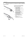 12
12
-
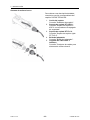 13
13
-
 14
14
-
 15
15
-
 16
16
-
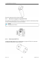 17
17
-
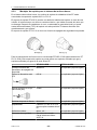 18
18
-
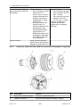 19
19
-
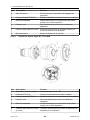 20
20
-
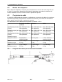 21
21
-
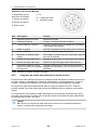 22
22
-
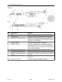 23
23
-
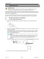 24
24
-
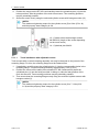 25
25
-
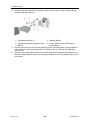 26
26
-
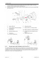 27
27
-
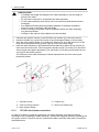 28
28
-
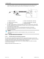 29
29
-
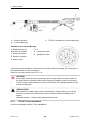 30
30
-
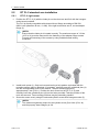 31
31
-
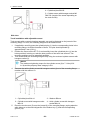 32
32
-
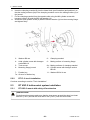 33
33
-
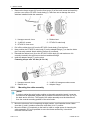 34
34
-
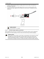 35
35
-
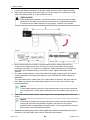 36
36
-
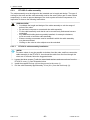 37
37
-
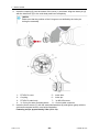 38
38
-
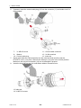 39
39
-
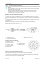 40
40
-
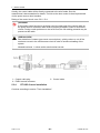 41
41
-
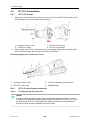 42
42
-
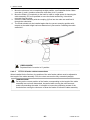 43
43
-
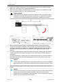 44
44
-
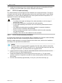 45
45
-
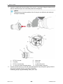 46
46
-
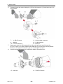 47
47
-
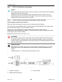 48
48
-
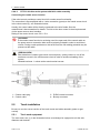 49
49
-
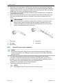 50
50
-
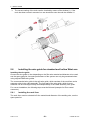 51
51
-
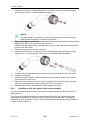 52
52
-
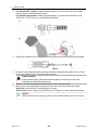 53
53
-
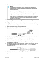 54
54
-
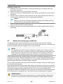 55
55
-
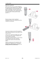 56
56
-
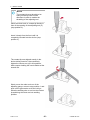 57
57
-
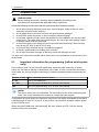 58
58
-
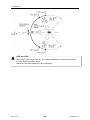 59
59
-
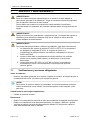 60
60
-
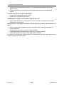 61
61
-
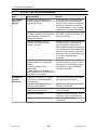 62
62
-
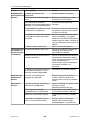 63
63
-
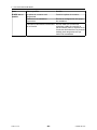 64
64
-
 65
65
-
 66
66


ESAB RT Robo Welding Torch System Manual de usuario
- Tipo
- Manual de usuario
en otros idiomas
Artículos relacionados
-
ESAB RT Robo Welding Torch System Manual de usuario
-
-
ESAB Robust Feed Pulse Manual de usuario
-
ESAB Mig 4004i Pulse, Mig 4004i Pulse WeldCloud™ Manual de usuario
-
ESAB Railtrac™ B42V Manual de usuario
-
-
-
ESAB PSF 520w Manual de usuario
-
ESAB MXL 341 Manual de usuario
-
ESAB RoboFeed 3004HW, FeedControl 3004HW Manual de usuario