Yamaha V1 Manual de usuario
- Categoría
- Mezcladores de audio
- Tipo
- Manual de usuario
Este manual también es adecuado para

EE
PM1D System Software V1.5
Supplementary Manual

PM1D System Software V1.5 Supplementary Manual
2
Copyright
Copying or distributing this manual in part or in whole using any method without the written permission of
Yamaha Corporation is prohibited.
Tr ade marks
Company names and product names are trademarks and registered trademarks of their respective owners.
Symbols such as ® and TM are not explicitly given in this document.
The illustrations and LCD screens as shown in this owner’s manual are for instructional purposes only, and may
appear somewhat different from those on your instrument.

Contents
3
Contents
Additions/changes in V1.5. . . . . . . . . . . . . . . . 4
Changes to the constantly-displayed screen. . 6
Upper part of the display . . . . . . . . . . . . . . . 6
Lower part of the display. . . . . . . . . . . . . . . . 8
DUAL CONSOLE mode added . . . . . . . . . . . . 11
About Dual Console mode . . . . . . . . . . . . . 11
About scene/library memories. . . . . . . . . . . 13
About the console shutdown function. . . . . 14
DUAL CONSOLE screen . . . . . . . . . . . . . . . 14
Connections in Dual Console mode . . . . . . 17
Establishing communication between con-
soles . . . . . . . . . . . . . . . . . . . . . . . . . . . . . 18
Transmitting only the necessary scenes / li-
braries. . . . . . . . . . . . . . . . . . . . . . . . . . . . 21
Limitations of Dual Console mode. . . . . . . . 21
Powering-off the consoles . . . . . . . . . . . . . . 26
Cascade connections . . . . . . . . . . . . . . . . . . . 27
About cascade connections. . . . . . . . . . . . . 27
CASCADE screen. . . . . . . . . . . . . . . . . . . . . 27
Cascade connections . . . . . . . . . . . . . . . . . 29
Establishing a cascade connection. . . . . . . . 31
Cautions when using cascade connection . . 33
Using GPI (General Purpose Interface) . . . . . 35
GPI screen. . . . . . . . . . . . . . . . . . . . . . . . . . 36
Using GPI IN . . . . . . . . . . . . . . . . . . . . . . . . 40
Using GPI OUT . . . . . . . . . . . . . . . . . . . . . . 41
Fader Start function . . . . . . . . . . . . . . . . . . . . 42
FADER START screen . . . . . . . . . . . . . . . . . . 43
Using the Fader Start function. . . . . . . . . . . 45
Tap Tempo function. . . . . . . . . . . . . . . . . . . . 51
Added functions in the USER DEFINE screen 52
Input channel panel assignments . . . . . . . . . 52
PANEL ASSIGN screen. . . . . . . . . . . . . . . . . 52
Switching the panel assign setting . . . . . . . 55
Horizontal pair and vertical pair . . . . . . . . . . 56
Mix minus. . . . . . . . . . . . . . . . . . . . . . . . . . . . 58
New functions in the PAN/ROUTING screen 58
Using mix minus . . . . . . . . . . . . . . . . . . . . . 59
Cautions regarding mix minus . . . . . . . . . . 60
Job select . . . . . . . . . . . . . . . . . . . . . . . . . . . . 61
Mix send on/off . . . . . . . . . . . . . . . . . . . . . 61
Mix send point . . . . . . . . . . . . . . . . . . . . . . 62
Mix send level. . . . . . . . . . . . . . . . . . . . . . . 62
Mix send pan/balance. . . . . . . . . . . . . . . . . 63
Auto Store function . . . . . . . . . . . . . . . . . . . . .64
Using Auto Store from the screen . . . . . . . . 64
Using Auto Store from the [STORE] switch . .65
Global Paste function . . . . . . . . . . . . . . . . . . .66
GLOBAL PASTE screen . . . . . . . . . . . . . . . . 66
Using the Global Paste function . . . . . . . . . .68
Parameter control via CONTROL CHANGE and
NRPN . . . . . . . . . . . . . . . . . . . . . . . . . . . . . . .71
MIDI CTRL CHANGE screen . . . . . . . . . . . . 71
Using CONTROL CHANGE / NRPN messag-
es to record/play parameter changes . . . . .74
Manual Fading function . . . . . . . . . . . . . . . . 76
New functions in the FADE TIME screen . . . 76
Using Manual Fading (1) . . . . . . . . . . . . . . 76
Using Manual Fading (2) . . . . . . . . . . . . . . .78
Unit name . . . . . . . . . . . . . . . . . . . . . . . . . . . .79
UNIT NAME screen. . . . . . . . . . . . . . . . . . . 79
Naming a unit/port . . . . . . . . . . . . . . . . . . .81
Matrix send shortcuts . . . . . . . . . . . . . . . . . . .82
DCA mute indicator . . . . . . . . . . . . . . . . . . . . 85
Oscillator improvements . . . . . . . . . . . . . . . . .86
Improvements in the OSCILLATOR screen . 86
Improvements in the INPUT PATCH / OUT-
PUT PATCH screens . . . . . . . . . . . . . . . . . . . .89
USB PC (computer) connection . . . . . . . . . . 89
Automatic scrolling in the CH to MIX screen
and MATRIX/ST ROUTING screen. . . . . . . . 90
ON/OFF button for COMM IN . . . . . . . . . . . .91
Added functions in the PREFERENCE screen. .92
Supplementary explanation for existing func-
tions . . . . . . . . . . . . . . . . . . . . . . . . . . . . . . . 93
Scene Memory/Effect Library to Program
Change Table. . . . . . . . . . . . . . . . . . . . . . . . .94
MIDI control change NRPN (Non Registered
Parameter Number) assignment table . . . . 94
MIDI control change parameter assignment
table . . . . . . . . . . . . . . . . . . . . . . . . . . . . . . . .97
MIDI Data Format . . . . . . . . . . . . . . . . . . . . .100

PM1D System Software V1.5 Supplementary Manual
4
This manual explains the functionality that has been added or changed in PM1D system software V1.5. Please
refer to the original manual in conjunction with this manual.
*In cases where the display of the console (CS1D) differs from the screen of the PM1D Manager application program,
explanations that apply only to PM1D Manager are indicated as [PM1D Manager].
Additions/changes in V1.5
This section briefly summarizes the additions and changes in PM1D system software V1.5. For details on each
function, refer to the appropriate page.
■
Changes to the constantly-displayed
screen
Major changes have been made to the items that are
always shown in the top and bottom of the screen
(
→
p.6).
■
New DUAL CONSOLE mode
As an operation mode of the PM1D system, a DUAL
CONSOLE mode has been added, allowing two con-
soles to be used with one system (
→
p.11).
■
Cascade connection
Two systems can now be cascade-connected. A cas-
cade-connected system can send any bus output to
the same bus of the other system (
→
p.27).
■
GPI connector is now enabled
The D-sub 25 pin GPI connector provided on the
console and engine can now be used to input/output
eight channels of control signals (
→
p.35).
■
REMOTE connector is now enabled
The D-sub 9-pin REMOTE connector of the console
and engine can now be used to control a recorder or
other device (
→
p.35).
■
Fader Start function
You can now specify that various commands be
transmitted from an assigned connector when the
level of a specified channel is raised above –60 dB or
lowered to –
∞
dB (
→
p.42).
■
Tap tempo function
A “tap tempo” function has been added, allowing
you to manually set the TEMPO parameter of an
internal effect by tapping an external switch con-
nected to the GPI connector (
→
p.51).
■
Expanded USER DEFINE functions
In conjunction with the addition of various func-
tionality, the user-definable functions have been sig-
nificantly expanded (
→
p.52).
■
Input channel panel assignment can
now be selected
The input channels assigned to INPUT blocks 1–4 of
the console can now be freely specified in blocks of
twelve consecutive channels. Similarly, the ST IN
channels assigned to ST IN blocks 1–2 can also be
assigned in blocks of two adjacent channels (
→
p.52).
Also, the DISPLAY SELECT section of the TRACK-
ING RECALL screen now has an INPUT [PANEL]
button that causes the current panel assignment state
to be displayed in the screen.
■
New pairing mode
In addition to the existing pairing mode in which
adjacent input channels 1+2, 3+4, ... can be paired,
you can now use “vertical pairing mode” in which
input channels 1+49, 2+50 ... are paired. This mode
allows you to use a single fader as if it were a stereo
fader (
→
p.56).
■
Mix minus setting
A MIX MINUS button has been added to the CH to
MIX screen of the PAN/ROUTING function. This
button provides a simple way to subtract only a spe-
cific channel from the signal that is being sent to a
certain MIX bus. This is useful when a performer or
announcer wishes to monitor the sound without his
own voice (
→
p.58).
■
Job select
Now you can move the cursor to a parameter and
press the [SHIFT] + [ENTER] keys to access a
popup-menu that lists the jobs available for that
parameter. The cursor will turn yellow to indicate
parameters for which you can use this function
(
→
p.61).
■
Auto Store function
When storing a scene, you can now use an “Auto
Store function” that automatically selects the unit,
patch, or name library number and title (
→
p.64).
■
Global Paste function
Using the new “Global Paste function,” the settings of
any channel or parameter in the current scene can be
copied and pasted to one or more scenes in scene
memory. This is a convenient way by which changes
in the current scene can be applied to previously-
stored scenes (
→
p.66).

Additions/changes in V1.5
5
■
Operate parameters via control
changes
Now you can use MIDI control changes to remotely
control PM1D parameters from an external device,
or transmit console operations as control changes
(
→
p.71).
■
Manual fading
A new “Manual Fading” function has been added.
When recalling a scene for which a fade time has
been set, you can now use the [DATA] encoder to
fade in the positive or negative direction. This is con-
venient when you want to vary the volume in con-
junction with action on stage (
→
p.76).
■
Unit name
You can now assign a unit name to each port of an
input/output unit or card. If necessary, the unit
name of each port can be displayed in the field in
which the short name of an input channel was shown
in the screen (
→
p.79).
■
Matrix send shortcut
The send level from a MIX channel or STEREO A/B
channel to a MATRIX channel can now be controlled
from a panel encoder (
→
p.82).
■
DCA mute indicator
When you mute a DCA group, the [ASSIGN DCA]
LED of the channels associated with that DCA can
now be made to blink if desired. This is convenient
when you want to know which channels are actually
being muted (
→
p.85).
■
Improved oscillator
The oscillator now lets you use two sine waves simul-
taneously. You can specify the frequency and level for
each, and output them independently to odd-num-
bered / even-numbered channels (
→
p.86).
■
Improvements in the INPUT PATCH /
OUTPUT PATCH screens
The unit name of each port is now displayed in the
UNIT PATCH / OUTPUT PATCH screens. Vertical
and horizontal red lines can also indicate the cur-
rently selected grid (
→
p.89).
■
USB connection to a PC
In addition to the serial connection supported on
earlier versions, you can now use a USB connection
to connect the PM1D to a PC (
→
p.89).
■
Improved operation in the CH to MIX
and MATRIX/ST ROUTING screens
Cursor movement now follows scrolling in the CH to
MIX function of the PAN/ROUTING function and
in the MATRIX/ST ROUTING screen of the
MATRIX/ST function (
→
p.90).
■
ON/OFF button added to COMM IN
The COMM IN function can now be turned ON/
OFF independently (
→
p.91).
■
Additional functions in the PREFER-
ENCE screen
A variety of setting items have been added in the
PREFERENCE screen (
→
p.92).
■
Channel selection can now be sepa-
rately specified for the AUTO DISPLAY
function (SELECTED CH ON/OFF but-
ton)
One of the AUTO DISPLAY functions automatically
moves the cursor to the corresponding parameter
when you switch the channel that is being operated.
In the PREFERENCE screen AUTO DISPLAY sec-
tion, this function can now be switched on/off inde-
pendently of the other AUTO DISPLAY items
(
→
p.92).

PM1D System Software V1.5 Supplementary Manual
6
Changes to the constantly-displayed screen
In PM1D system software V1.5, the following changes have been made to the items that are always shown in
the top and bottom of the console display.
Upper part of the display
1
DISPLAY FUNCTION
Shows the currently selected function as an abbrevia-
tion.
Hint
Click this to switch between the FUNCTION MENU
screen and the screen of the currently selected func-
tion. (Equivalent to the MENU button of the previ-
ous version.)
2
CONNECTION
Indicates the status of the connections between the
engine(s) and console(s).
•
Console 1/2
If DUAL CONSOLE is selected as the console opera-
tion mode (SYSTEM CONFIGURATION in the
SYSTEM CONNECTION screen, etc.), this indicates
whether that console (CS1D) is specified as console 1
or as console 2 (
→
p.19).
The color of this numeral will depend on how CAS-
CADE is set for the operation mode. In the case of
CASCADE OFF or CASCADE ON [MASTER], this
numeral will be white on a black background. If
CASCADE ON [SLAVE], this numeral will be black
on a white background.
If cascade communication between the systems
cannot be established even though CASCADE
ON is selected, this numeral will blink.
•
DUAL
If DUAL CONSOLE is selected as the operation
mode for the console, “DUAL” will be displayed here
(
→
p.19).
If communication between the consoles cannot
be established even though DUAL CONSOLE
mode is selected, an X mark will be displayed
over the “DUAL” indication.
•
Engine A/B
If the PM1D system is being used in mirror mode,
this indicates which engine (A or B) is currently
enabled, and the number of usable channels. The
enabled engine is shown on a green background. You
can also click this button to switch between engines
A/B.
If the engine that should be enabled is not oper-
ating normally, or if the connection has been
broken, an X mark will be displayed over the A
or B symbol.
3
PANEL STATUS
Indicates the current panel assignment (the channel
numbers assigned to the INPUT block / ST IN
block).
4
FADER FLIP
Indicates the state of the FADER FLIP switch located
on the console panel (i.e., whether [MIX] or [CH] is
on). You can also use these buttons to switch [MIX]
and [CH].
Hint
If the FADER FLIP LINK button is turned off in the
UTILITY function PANEL ASSIGN screen (a new
screen added in V1.5), fader flip can be switched
independently for INPUT blocks 1/2 (left) and 3/4
(right) (
→
p.54).
1 2 3 5 6
4
Console 1/2
DUAL Engine A/B

Changes to the constantly-displayed screen
7
5 SCENE MEMORY
Displays the number and title used when most
recently recalling/storing the currently selected scene
memory. Depending on the state of the scene, the
following symbols may be displayed in the margin of
the SCENE MEMORY field.
• EDIT
This symbol will be displayed if you edit a parameter
of a scene, patch, unit, or name after recalling/storing
a scene memory. When you recall/store a scene
memory, this symbol will disappear. (However, it
may not disappear if Recall Safe is turned on.)
• TC
This symbol will be displayed if the EVENT
RECALLING button is set to ENABLE in the TC
EVENT screen. You cannot rewrite scene memories
or patch/unit/name libraries while this symbol is dis-
played. This means that you will also be unable to use
functions such as store, undo store, link on/off, title
editing, sort, or load.
• PREVIEW
In PREVIEW mode, this symbol will be displayed.
In PREVIEW mode, the scene number and title will
be displayed in white characters on a red back-
ground.
• READ ONLY
• PROTECT
The READ ONLY symbol will be displayed if the
scene currently selected for store/recall is read-only
(00.0-00.9). The PROTECT symbol will be displayed
if protect is turned on.
6 Other symbols
The following symbols will be displayed at the upper
right of the display according to the state of the con-
sole.
• SOLO/CUE
According to the current solo or cue state, this area
will display the following symbols:
SOLO, EFFECT CUE, SUBIN CUE, INPUT CUE,
DCA CUE, OUTPUT CUE, KEY IN CUE
• TB/OSC (Talkback / Oscillator)
The TB symbol will be displayed if talkback is on,
and the OSC symbol will be displayed if the oscillator
is on.
Hint
If the above operations occur simultaneously, they
will be displayed in the order of TB → OSC.
• COMM IN (Communication In)
If COMM IN is turned on in the MONITOR A
screen, the COMM IN symbol will be displayed on a
green background. In addition if a port is assigned to
COMM IN, the background of this symbol will
change to red when the input signal passes through
the COMM IN gate.
• LCR
The LCR symbol will be displayed if LCR is turned
on for at least one input channel or output channel
(in the LCR screen of the PAN/ROUTING or
MATRIX/ST function). In addition if the CENTER
BUS CONTROL button (in the LCR screen of the
PAN/ROUTING or MATRIX/ST function) is on, the
LCR [B] symbol will be displayed.
• RS422, MIDI, BUSY
- RS422
This symbol will be displayed when a response to a
transport command sent via the RS422 connector
is received.
- MIDI
This symbol will be displayed when a program
change or control change is received.
- BUSY
This symbol will be displayed during startup or
while internal memory or a PC card file is being
accessed.
Hint
• If the above states occur simultaneously, they will
be displayed in descending priority of RS422 →
MIDI → BUSY.
• The RS422 and MIDI symbols will remain visible
for approximately 200 msec after reception is com-
pleted.
• The BUSY symbol will disappear immediately
when access is completed.
• MANUAL FADE, AUTO FADE, TRACKING
ENABLE
- MANUAL FADE
This symbol will be displayed if Manual Fading is
enabled (even if a fade operation is not actually
being performed) (→p.76).
- AUTO FADE
This symbol will be displayed while Auto Fading is
being executed.
- TRACKING (Tracking Recall)
This symbol will be displayed if tracking recall is
enabled (the TRACKING RECALL button is set to
ENABLE in the TRACKING RECALL screen).
Hint
If the above states occur simultaneously, they will be
displayed in descending priority of MANUAL FADE
→ AUTO FADE → TRACKING.

PM1D System Software V1.5 Supplementary Manual
8
[PM1D Manager]
In PM1D Manager, the following information will be displayed instead of 3 PANEL STATUS and 4 FADER
FLIP described on page 6.
1 Connection status
This area of the PM1D Manager screen will indicate
the status of the connection between the PC and the
console or engine.
• ........... Indicates that a cable is con-
nected between the PC and
console or engine, but com-
munication has not been
established.
• ........... Indicates that a cable is con-
nected between the PC and
console or engine, and that
communication has been
established. In this state, the
PM1D system can be con-
trolled from the computer.
• ...........Indicates that either the
cable is not connected,
or that the other device
is not powered-on.
2 Connection destination / connection
method
In OFFLINE or ONLINE states, this area will
show a graphic that indicates the connection des-
tination (console or engine), and the connector
(COM port name or USB port name) that is
selected in the Communication Port (Option
menu) of Communication Setup.
Lower part of the display
The lower part of the display is divided into the following four parts. Click the √/® buttons at the lower left of the
screen to switch the items that are shown.
■ CONSOLE STATUS
1 Select buttons
Click the √/® buttons to switch the items that are
displayed.
2 IN SEL (Selected input channel)
Indicates the input channel that is currently selected
by the [SEL] switch.
3 NAME MODE
Selects whether the display will show the short name
of the input channel (CH NAME), or the name of
the unit assigned to that input channel (UNIT
NAME) (→p.79).
4 MODULE FLIP
Indicates the on/off state of the MODULE [FLIP]
switch in the SELECTED INPUT CHANNEL block.
You can also click this button to change the module
flip setting.
Hint
• If the PATTERN CHANGE button is turned on in
the MODULE FLIP BUTTON MODE section of
the UTILITY function PANEL ASSIGN screen (a
new screen added in V1.5), the indications of these
buttons will change to “PATT.” In this case, they are
used to switch channel assign patterns for the
INPUT block (→p.52).
• If the MODULE FLIP / PATTERN CHANGE
LINK button in the same screen is turned off, set-
tings for module flip and patterns can be made
independently for the left and right INPUT blocks
(→p.54).
21
2 3 4 65 71

Changes to the constantly-displayed screen
9
5 MIX SEND NO. (Mix send number)
Indicates the number of the MIX bus that is cur-
rently selected as the send destination for INPUT
blocks 1–4.
6 MASTER FADER
Indicates the function that is currently assigned to
DCA faders 1–12 (DCA GROUP block).
7 OUT SEL (Selected output channel)
Indicates the output channel that is currently
selected by the [SEL] switch.
[PM1D Manager]
In PM1D Manager, the following information will be displayed instead of 4–6 described above.
1 DIRECT RECALL / MUTE MASTER
According to the setting of the RECALL button or
MUTE button, these buttons either directly recall
twelve previously-assigned scenes, or switch mute
groups 1–12 on/off. These buttons have the same
function as SCENE MEMORY [1]–[12] switches on
the panel of the console.
■ USER DEFINE
1 Select buttons
Click the √/® buttons to switch the items that are
displayed. If you click the middle, you will return to
the CONSOLE STATUS display.
2 User define buttons
These list the functions that are assigned to the USER
DEFINE [1]–[8] switches in the USER DEFINE
block of the console. You can also click a button to
execute the corresponding function.
Hint
Functions for the USER DEFINE [1]–[8] switches
can be assigned in the UTILITY function USER
DEFINE screen.
1
1 2

PM1D System Software V1.5 Supplementary Manual
10
■ CONSOLE GPI IN
1 Select buttons
Click the √/® buttons to switch the items that are
displayed. If you click the middle, you will return to
the CONSOLE STATUS display.
2 Console GPI IN test buttons
These buttons list the functions that are assigned via
the GPI connector of the console to GPI IN (ports 1–
8). You can also click a button to test the correspond-
ing function (→p.40).
Hint
• Functions for the GPI IN test buttons can be
assigned in the MIDI/GPI/TC function GPI screen.
• Even if you are not using the GPI port, you can use
these buttons in place of the USER DEFINE
switches by assigning functions to the GPI IN test
buttons.
■ ENGINE GPI IN
1 Select buttons
Click the √/® buttons to switch the items that are
displayed. If you click the middle, you will return to
the CONSOLE STATUS display.
2 Engine GPI IN test buttons
These buttons list the functions that are assigned via
the GPI connector of the engine to GPI IN (ports 1–
8). You can also click a button to test the correspond-
ing function (→p.40).
Hint
• Functions for the GPI IN test buttons can be
assigned in the MIDI/GPI/TC function GPI screen.
• Even if you are not using the GPI port, you can use
these buttons in place of the USER DEFINE
switches by assigning functions to the GPI IN test
buttons.
Since the GPI IN of the engine can be controlled
only from console 1, the GPI IN test buttons will
not be displayed in DUAL CONSOLE mode if con-
sole 2 is specified.
However in PM1D Manager, the display is not
restricted even if console 2 is specified in DUAL
CONSOLE mode when OFFLINE.
1 2
1 2

DUAL CONSOLE mode added
11
DUAL CONSOLE mode added
As an operation mode of the PM1D system, version 1.5 adds Dual Console mode, in which two console are
used by one system. The functionality and operation of Dual Console mode is explained below.
In the following explanation, functions and operations that apply only to console 1 are indicated as [Console
1], and functions and operations that apply only to console 2 as [Console 2].
If the console (CS1D) you are using was manufactured before June 2002, you may be unable to select Dual Console
mode even if connections are correct. In this case, you will need to have a gate array rewritten in order to use Dual
Console mode. Please contact your Yamaha dealer.
It is necessary to have the gate array rewritten only if you wish to use Dual Console mode. If you are using the sys-
tem in other modes, rewriting is not necessary, and you may continue using the system without change.
About Dual Console mode
Dual Console mode is a mode in which two consoles
(CS1D) are used in a single PM1D system. In this mode,
two consoles share one (in standard mode) or two (in
mirror mode) engines (DSP1D-EX {DSP1D}). Here are
some examples of how Dual Console mode can be used:
• Use two consoles to control the main mix and mon-
itor mix
In this application, the same input channels are
patched to the panels of both consoles. One engineer
controls the main mix, and another engineer con-
trols the monitor mix.
• Use two consoles to control the same mix from two
locations
In this application, two consoles are placed in sepa-
rate locations (for example one near the stage and
the other in the audience seating), and two engineers
control the same mix.
• Use two consoles to control 96 channels simulta-
neously
In this application, input channels 1–48 are patched
to one console, and input channels 49–96 to the
other console, allowing one or more engineers to
control 96 channels simultaneously.
In Dual Console mode, the console that is connected
to the engine will operate as the master unit, and the
other console will operate as the slave unit. However,
in order to avoid confusion with the master/slave
relationship in “engine cascade” (described later in
this document), we refer to the master unit as “con-
sole 1,” and the slave unit as “console 2.”
Console 1 and console 2 differ in the functions they can
control, and in the order of priority when operations
overlap. The differences between consoles 1 and 2 can be
summarized as follows.
• Items that are linked between consoles 1 and 2
In general, changes that you make to the mix param-
eters in the current scene are linked between consoles
1 and 2. (An operation on one console will be
reflected by the other.) Operations of console 2 will
not nullify operations of console 1. Even if differ-
ences occur between the states of console 1 and con-
sole 2, the engine will always be set according to
console 1. If a difference occurs between parameters
that should be linked, you can select whether to copy
all scenes and all libraries when connection occurs,
or to copy them as desired after connection.
• Items that are operated independently between
consoles 1 and 2
Channel selections by the [SEL] switches, changes in
panel layout such as fader flip or module flip, and
screen switching by the function switches are not
linked between consoles. These operations can be
made independently on each console.
• Items that can be operated only by console 1
Most operations that affect the core of the system,
such as switching between engines, switching the
word clock master, and changing the connections
between components, can be performed only by con-
sole 1. The settings of most items can be viewed on
the console 2 screen, but cannot be modified.
• PC connection
A PC (PM1D Manager) can be connected only to
console 1 or to the engine. It cannot be connected to
console 2. Nor is it possible to connect and use two
or more PCs simultaneously.
Whether a parameter is linked when operated, and
the priority between consoles 1 and 2, will differ
depending on the screen. The table on the following
page summarizes the operation of each screen in
Dual Console mode.

PM1D System Software V1.5 Supplementary Manual
12
Function Screen
Linked
Indepen-
dent
Remarks
1
→21↔2
EFFECT
O
GEQ
O
SCENE
MEMORY
q
Only the trigger for number and store/recall operations is
transmitted and received.
SORT-related settings can be operated only on console 1
RECALL SAFE
O
FADE TIME
O
DIRECT RECALL
O
TRACKING RECALL
O
GLOBAL PASTE
O
MIDI/GPI/TC
MIDI PGM CHANGE
O
MIDI CTRL CHANGE
O
GPI
q
• GPI IN settings
Console 1 or PC:
Only console 1 / engine port can be set
Console 2:
Only console 2 port can be set
• GPI OUT settings
Console 1 or PC:
Only console 1 / engine port can be set
Console 2:
Only console 2 port can be set. However, engine port can
be viewed
TC EVENT
O
FADER START
O
Cannot be set on a PC connected to a system that includes
a console
UTILITY
PREFERENCE
O
USER DEFINE
O
From system software 1.5, this can be set/operated indepen-
dently for consoles 1 and 2 and the PC
LOAD / SAVE
O
There are limitations on the parameters that can be loaded
by console 2
PANEL ASSIGN
O
PAIR MODE
O
SYS/W.CLOCK
SYSTEM
CONNECTION
q
Buttons that switch the wiring of console 2 itself can also be
operated from console 2
DUAL CONSOLE
O
CASCADE
O
INPUT UNIT
q
Virtual units can be created only from console 1.
Unit parameters are linked.
OUTPUT UNIT
q
Virtual units can be created only from console 1.
Unit parameters are linked.
WORD CLOCK
O
DITHER
O
UNIT NAME
O
METER
q
METERING POINT and PEAK HOLD can be operated only
from console 1
MON/CUE
TALKBACK
q Only TB OUT is in common
OSCILLATOR
O The two consoles share one 2CH set of oscillators.
2TR IN
q
Settings other than INPUT CONSOLE can also be operated
from console 2
ST OUT DIGITAL
O
MONITOR A
O
MONITOR B
—— —
Cannot be operated, since in Dual Console mode, this func-
tions as MONITOR A of the other console
CUE/SOLO
q
Cue is independent, solo function on/off can be operated
only from console 1
Linked if the CUE MODE button is set to SOLO ON, or if in
the SYS/W.CLOCK function DUAL CONSOLE screen CUE
ON/OFF is turned ON.

DUAL CONSOLE mode added
13
• Linked (1→2).............Screens in which the con-
sole 1/2 settings are linked.
However, they can be oper-
ated only by console 1.
• Linked (1↔2).............Screens in which the con-
sole 1/2 settings are linked.
They can be operated from
either console 1 or 2.
• Independent...............Screens in which settings
can be made independently
by consoles1 and 2.
• O ..................................Indicates that all parame-
ters in the corresponding
function/screen will operate
as indicated (independent,
linked 1→2, or linked
1↔2).
•
qq
qq
.................................Indicates that some param-
eters in this function/screen
are exceptions, and operate
other than indicated.
About scene/library memories
When a scene or library is stored or recalled on one con-
sole, the other will follow this operation. However, this
simply means that a command of “recall scene number
***.*” is transmitted to the other console; the result of
the store/recall is not conveyed to the other console.
Thus, in order to completely synchronize the two con-
soles, it is necessary to match the current memory (the
scene, patch, units, names currently shown in the
panel), the scene memories and libraries that are used,
and some of the setup data.
If this data does not match, scene/library recall opera-
tions may cause the settings of the current scene to
become completely different between the two consoles.
Data can be synchronized between the two consoles in
the following ways.
• Tr ansfer all data
In this method, all data is transmitted via the CON-
TROL I/O connector from console 1 to console 2.
You can perform this operation in a single step when
you initiate Dual Console mode.
• Tr ansfer only necessary data
In this method, only the scenes and libraries that will
be used are manually transmitted from console 1 to
console 2.
• Tr ansfer all data via memory card
In this method, all data of console 1 is saved on a
memory card, and this data is then loaded into con-
sole 2. To use this method, use the LOAD/SAVE
screen of console 1 to save all data on a memory card,
then insert that card into console 2 and load the data.
(For details, refer to “CS1D Reference Manual (Soft-
ware),” p.40.)
OUT PATCH
OUTPUT PATCH
O
If a discrepancy occurs between the patching when a scene/
unit is recalled, the patching of console 1 will take priority
INSERT PATCH
O
INSERT POINT
O
INSERT VIEW
O
NAME
O
OUT INSERT
O
OUT EQ
O
OUT COMP
O
OUT DELAY
O
OUT DCA MUTE
O
MATRIX/ST
O
OUT CH VIEW
O
IN PATCH
INPUT PATCH
O
If a discrepancy occurs between the patching when a scene/
unit is recalled, the patching of console 1 will take priority
DIRECT OUT PATCH
O
INSERT PATCH
O
INSERT/DIRECT POINT
O
INSERT/DIRECT VIEW
O
NAME
O
HA/INSERT
O
IN EQ
O
IN GATE/COMP
O
IN DELAY
O
IN DCA/MUTE
O
PAN/ROUTING
O
INPUT CH VIEW
O
Function Screen
Linked
Indepen-
dent
Remarks
1→21↔2

PM1D System Software V1.5 Supplementary Manual
14
About the console shutdown function
A Shutdown function has been added to keep current memory from being modified in Dual Console mode.
In Dual Console mode, powering-off either console may modify the current memory of the other console or
the engine, but by shutting-down the console before powering it off, you can prevent current memory from
being modified.
For the procedure, refer to page 26.
• This shutdown function is necessary only in Dual Console mode. If you are not operating in Dual Console mode,
the SHUTDOWN button (→p.26) will not be displayed.
• If you power-off the console without performing this procedure as described, the current memory used by the
other console or the engine may be modified. However, settings other than current memory (i.e., scene memory,
the various setup memories and libraries) will not be affected. Thus, if you have stored the current memory to a
scene, you can re-recall that scene to recover from an accidental power-off that occurred without performing the
shutdown.
DUAL CONSOLE screen
PM1D system software V1.5 adds a DUAL CONSOLE screen to the SYS/W.CLOCK function. In this screen you can make
settings and perform operations for Dual Console mode.

DUAL CONSOLE mode added
15
1 SYSTEM CONFIGURATION
Indicates the current operation mode and cascade
mode of the PM1D system. Click the button to
open the SYSTEM CONFIGURATION popup win-
dow, where you can switch the operation mode and
cascade mode.
Hint
The SYSTEM CONFIGURATION field is displayed
in the SYS/W.CLOCK function SYSTEM CONNEC-
TION screen, DUAL CONSOLE screen, and CAS-
CADE screen (newly added in version 1.5). All of
these represent the same setting.
2 DUAL CONSOLE LINK (DUAL CONSOLE mode
link settings)
Here you can select whether cue operation and talk-
back-controlled dimmer operation will be linked.
If the CUE ON/OFF LINK button is on, operations
of the [CUE] switches, EFFECT CUE, SUB IN CUE,
and gate KEY IN CUE will be linked.
If the TALKBACK DIMMER ON/OFF LINK button
is on, turning talkback on from one console will
attenuate the monitor signal on the other console as
well.
Note that the TALKBACK DIMMER ON/OFF
LINK button links the dimmer operation; it does
not link talkback on/off operation. The amount of
attenuation when the dimmer is on can be adjusted
independently in the MONITOR A screen of each
console.
1
2

PM1D System Software V1.5 Supplementary Manual
16
[Console 1]
The following screen appears only on console 1.
3 UPDATE
Each time you click this button, the current memory,
scene memories/libraries, and setup data will be
compared between console 1 and console 2, and the
ALL DATA STATUS (4) display will be updated.
4 ALL DATA STATUS
This area displays the result of comparing the data of
console 1 and 2. If all data is identical, this will indi-
cate “SAME.” If there is any difference, this will indi-
cate “DIFF.”
5 Scene memories / libraries
This area displays the result of comparing each scene
memory and library. You can click the buttons at the
left to select the items that will be displayed in the
library data list (7).
6 CURRENT MEMORY (Current memory status)
This indicates the result of comparing the current
memory (the scene currently reflected by the panel,
patches, units, and names). If these are all identical
for consoles 1 and 2, this will indicate “SAME.” If
there are any differences, this will indicate “DIFF.” If
you click the COPY button located in the cen-
ter, the current memory will be copied from console
1 to console 2.
7 Scene memory / library data list
This displays the scene memory / library data that is
selected by the scene memory / library status (5)
buttons.
The ALL field at the top of the list will indicate
“SAME” if all data matches, or “DIFF” if there is any
difference. If you click the COPY button
located in the center, the entire contents of the
selected scene memory or library will be copied from
console 1 to console 2.
The lower lines of the list show the contents of the
selected scene memories / libraries for each console.
If the contents of each number match, this will indi-
cate “SAME.” If they differ, this will indicate “DIFF.”
Only while a scene memory is displayed in the list,
clicking the COPY button located in the cen-
ter will copy the contents of that scene memory from
console 1 to console 2.
7
6
5
3
4

DUAL CONSOLE mode added
17
Connections in Dual Console mode
The following diagrams show connections between the consoles and engine(s) in Dual Console mode.
• You must power-off all equipment before making
connections.
• Connections for input/output units and power
supplies are not discussed here. For details, refer
to “CS1D Operation Manual, Setup.”
Please note that on console 2 you will connect the
DIGITAL I/O lines to the DIGITAL I/O ENGINE A
ports — not to the DIGITAL I/O CONSOLE ports.
[Standard mode]
IN OUT
IN OUT
INOUT
1212 121212
12
121212
12 12
12
IN OUT
ENGINE A
(DSP1D-EX{DSP1D})
CONTROL
I/O
CONSOLE
I/O
CONSOLE 1 (CS1D)
CONTROL I/O
CONSOLE
CONTROL I/O
ENGINE A
DIGITAL I/O
ENGINE A
DIGITAL I/O
CONSOLE
CONSOLE 2 (CS1D)
CONTROL I/O
CONSOLE
DIGITAL I/O
ENGINE A

PM1D System Software V1.5 Supplementary Manual
18
[Mirror mode]
Hint
• The dashed lines in the above diagram are spare
connections for use in the event that the currently-
valid connectors become unusable.
• The system will operate normally even with just
the connections shown by the solid lines. However,
we recommend that you also make the spare con-
nections shown above whenever possible.
Connect each device to the identically-numbered (1
or 2) connector on each device. The system will not
operate correctly if you connect differently-num-
bered connectors.
Establishing communication between consoles
This section explains how to select Dual Console mode on each console, specify the console to which the engine is con-
nected as “console 1,” specify the other console as “console 2,” and establish communication.
In order to use Dual Console mode, each console
number must be specified correctly. Be aware that
communication will not occur if consoles 1 and 2
are interchanged, or if both are set to console 1.
1. Turn on the power in the order of input/output
units, engine(s), and console power supply.
Incorrect operation while making settings can
cause a high-volume signal to be output. We
strongly recommend that you turn down the vol-
ume of your power amps etc. until settings are
completed.
IN OUT
IN OUT
INOUT
1212 121212
12
121212
12 12
12
IN OUT
ENGINE A
(DSP1D-EX{DSP1D})
CONTROL
I/O
CONSOLE
I/O
CONSOLE 1 (CS1D)
CONTROL I/O
CONSOLE
DIGITAL I/O
CONSOLE
CONSOLE 2 (CS1D)
CONTROL I/O
CONSOLE
IN OUT
INOUT
12
121212
12 12
ENGINE B
(DSP1D-EX{DSP1D})
CONTROL
I/O
CONSOLE
I/O
CONTROL I/O
ENGINE A
DIGITAL I/O
ENGINE A
CONTROL I/O
ENGINE B
DIGITAL I/O
ENGINE B
DIGITAL I/O
ENGINE A

DUAL CONSOLE mode added
19
[Console 2]
2. On the console to which the engine is not connected,
access the SYS/W.CLOCK function DUAL CON-
SOLE screen (a newly added screen in version 1.5).
3. In the SYSTEM CONFIGURATION field, click the
button.
The SYSTEM CONFIGURATION popup window
will appear. In the OPERATION MODE SELECT
area of this window you can select the operation
mode of the PM1D system.
4. Click the DUAL button within the CONSOLE sec-
tion of the OPERATION MODE SELECT area.
When you turn the DUAL button on, the CONSOLE
No. buttons will become operable.
5. Click the CONSOLE 2 button to turn it on, and
then click the OK button.
The console will be set to DUAL CONSOLE mode.
In the upper part of the screen, the control number
of the CONNECTION field will change to “2,” and
“DUAL” will be indicated below the number. (How-
ever, an X will be superimposed on DUAL since
communication is not yet established.)
[Console 1]
6. On the console to which the engine is connected,
access the SYSTEM CONFIGURATION popup win-
dow in the same way.
7. Click the DUAL button within the CONSOLE sec-
tion of the OPERATION MODE SELECT area.
8. Verify that the CONSOLE 1 button is on, and click
the OK button.
When you click the OK button, the two consoles will
attempt to establish communication. When commu-
nication has been established, console 1 will compare
the system version, scene memories, libraries, and
setup data of the two consoles.
• In order to use Dual Console mode, both con-
soles must have the same system version.
• If the versions of the two consoles differ, the ver-
sion check popup window will appear, and fur-
ther operation will not be possible. Update the
system version to match, and perform the opera-
tion once again.
If there is any difference in the data of the two con-
soles, the console 1 screen will show a message of
“Will transmit differential data to CONSOLE 2. Are
you sure? [xx sec.]”
This message is asking you whether it is OK to trans-
mit the differing data from console 1 to console 2.
(The data is always sent from console 1 to console 2.
The [xx sec.] (or [xx min.]) indicates the estimated
time required for transmission.
When you click the OK button in this window, all
current scene, scene, memory, and library data, and
any setup data required for linked operation will be
transmitted from console 1 to console 2.
If you click the CANCEL button, only the current
scene and the setup data necessary for linked opera-
tion will be transmitted from console 1 to console 2.
Hint
If the scene memories and libraries are fully used, it
will take approximately 60 minutes to transmit all of
the data.

PM1D System Software V1.5 Supplementary Manual
20
CAUTION!
• Be aware that once data transmission is started, it
cannot be aborted. Please use caution.
• The expected time is merely an estimate. A longer
time than indicated here may actually be required.
• If you do not have enough time for transmission to
be performed, we strongly recommend that you
click the CANCEL button when the above message
appears, and either transmit only the necessary
data (→p.21) or transfer the data via memory card.
9. If it is OK to transmit the data, click the OK button.
Data transmission will begin. The screen will show a
progress bar to indicate the state of progress.
• While transmission is occurring, never turn off
the power or interrupt communication. If for
some reason the console power supply is turned
off, the memory contents of console 2 will be lost.
In this case you will need to initialize console 2.
• Even if you click the CANCEL button in step 9,
part of the setup data and the current data will be
transmitted, so as long as you are operating the
current scene, the two consoles will operate in
tandem.
However, since the libraries and scene do not
match, performing a store/recall operation may
cause the current scene on the two consoles to
have completely different settings.
When transmission is completed, the X symbol will
disappear from the “DUAL” indication in the CON-
NECTION area at the top of the screen. Now the two
consoles can be used simultaneously.
Hint
• If you power-off the system in this state, console 1
will attempt to initiate communication in Dual
Console mode the next time it is powered-on.
• To cancel Dual Console mode, access the DUAL
CONSOLE screen on console 1 or 2, click the
button in the SYSTEM CONFIGURATION field,
and select SINGLE CONSOLE mode.
If Dual Console mode is established, switching to
Single Console mode will set both console 1 and
console 2 to Single Console mode.
If, after communication is established, communica-
tion with the DIGITAL I/O connector or CONTROL
I/O connector is interrupted, a warning message like
the following will appear in the lower part of the
screen. Please check the appropriate connection.

DUAL CONSOLE mode added
21
Transmitting only the necessary scenes / libraries
After establishing Dual Console mode communication, you can transmit only the necessary scene memories and librar-
ies from console 1 to console 2. Even if you have cancelled transmission of all data after starting-up Dual Console mode,
you can use this method to transmit only the minimum scenes and libraries.
The following procedure can be performed only on
console 1.
[Console 1]
1. On console 1, access the SYS/W.CLOCK function
DUAL CONSOLE screen.
2. In the ALL DATA STATUS section, click the
UPDATE button.
The memory contents of consoles 1 and 2 will be
compared. If they match perfectly, an indication of
“SAME” will appear at the right of the UPDATE but-
ton. If there is any difference, an indication of “DIFF”
will appear.
3. Click the scene memory / library status buttons to
select the scene memory / library that you want to
transmit.
The contents of the selected scene memory / library
will appear in the list at the right. If the identically-
numbered data matches between consoles 1 and 2,
the field at the right will indicate “SAME.” If the data
does not match, this field will indicate “DIFF.”
Hint
If no data has been saved in the identically-num-
bered memory of either console 1 or 2, this field will
indicate “SAME.”
4. Click the COPY ( ) button for the number
that you want to transmit.
The corresponding data will be copied from console
1 to console 2. Perform the same operation for other
numbers as desired.
• When copying a scene memory, you must also
copy the unit, patch, and name libraries used by
each scene.
• Individual numbers of library data cannot be
copied. The entire library will be copied as a
whole.
Limitations of Dual Console mode
This section explains the limitations of Dual Console mode.
■ Operation when the current memory
does not match
Dual Console mode can be used even if the current
memory (the scene, patches, units, and names currently
reflected by the panel) does not match. In this case, edit-
ing a linkable parameter from one console will cause
only the identical parameter on the other console to
change as well.
For operations such as setting/disabling a pair, switching
a MIX bus between VARI/FIX, and copying between
channels, only the appropriate number and command
are transmitted. If the received command conflicts with
the console’s own current memory, the setting of console
1 will always take priority. In this case, the lower part of
the console 2 will indicate “DATA TYPE CONFLICT!
EXCLUDED,” and it will not be possible to edit the
parameter on console 2.
Popup windows that ask you to change an internal set-
ting (such as switching units) will always appear only on
console 1. When you execute such a change on console 2,
a message will ask you for confirmation.
■ Scene memory store/recall operations
When you perform a scene memory store/recall opera-
tion on one console, the corresponding number along
with a store/recall command will be transmitted to the
other console. (The other console is not informed
whether the current memory or scene memory matches
following execution.)
This means that if changes occur in the contents of scene
memory, discrepancies may occur between the current
memories of the two consoles following a recall opera-
tion. Please be aware of this possibility.
Recall Undo or Store Undo can be performed from
either console. However if the scene memories are not
synchronized at the time of initial connection in Dual
Console mode, the scene number that is recalled by
Recall Undo may differ. In this case, undo will occur
with differing scene memories, and the engine will fol-
low the data of console 1.
Store Undo cannot be performed immediately after
Dual Console mode initial connection occurs.
■ Preview mode
Scene memory Preview mode can be operated indepen-
dently from either console. If one console is switched to
Preview mode, and an edited scene is stored, all data of
the corresponding scene will be copied to the same scene
number of the other console (the store-destination scene
will match).

PM1D System Software V1.5 Supplementary Manual
22
■ Library store/recall operations
When you perform a library store/recall operation on
one console, the corresponding number along with a
store/recall command will be transmitted to the other
console. (The other console is not informed whether the
library or current memory matches following execu-
tion.)
This means that if changes occur in the library contents,
discrepancies may occur in the current memories of the
two consoles following a recall operation. Please be
aware of this possibility.
As an exception, if you open the LIBRARY popup win-
dow on one console, edit the parameters directly and
then store, the data of the corresponding library will be
copied to the same library number on the other console.
(The store-destination library will match.)
■ File load/save operations
In Dual Console mode, you can use the LOAD/SAVE
screen to load/save data from or to a memory card on
either console. However on console 2, there are slight
limitations on the data that can be loaded from a mem-
ory card.
The following table shows the items that can be loaded
by each console in Dual Console mode.
■ Engine selection in Mirror mode
When using the PM1D system in Mirror mode, switch-
ing between engines A and B can be performed only
from console 1.
When the engine has switched, a message of “ENGINE
HAS BEEN SWITCHED TO [A] ([B])” will appear at
the bottom of the screen on console 2.
■ Talkback
In Dual Console mode, two talkback systems can be
operated independently from each console 1 and 2.
(Talkback will function with a total of four inputs / two
systems.)
For each console, you can use the MON/CUE function
TALKBACK screen to adjust the input level, phase, and
destination of the two talkbacks.
However, the settings of the TALKBACK screen TB OUT
section will be shared by console 1 and 2. In this section,
you can choose the talkback source as either CONSOLE
1 (talkback signal of console 1), CONSOLE 2 (talkback
signal of console 2), or CONSOLE 1+2 (talkback signals
of consoles 1 and 2), and specify the desired port as the
output destination. (This operation can be performed
from either console.)
If the TALKBACK DIMMER ON/OFF LINK button is
turned on in the DUAL CONSOLE screen of console 1,
the dimmer will operate on the other console as well
when talkback is turned on by one console. However
even in this case, talkback on/off operation is not linked.
The amount by which the signal is attenuated when the
dimmer is on can be adjusted independently for each
console in the MONITOR A screen.
Loaded item Console 1 Console 2
Scene memory
OO
Setup data
O q
1
1. Only the parameters that can be set independently for each
console will be loaded. Parameters that are linked with con-
sole 1 will not be loaded.
TC EVENT screen settings
OX
MIDI PGM CHANGE screen
settings
OX
Libraries
OO
O: Loadable q: Partially loadable X: Not loadable

DUAL CONSOLE mode added
23
■ Monitor
In Dual Console mode, one of the two monitor buses A
and B can be assigned to each console 1 and 2, and con-
trolled independently.
The monitor bus controlled by the console itself is
assigned to MONITOR A, and the monitor bus con-
trolled by the other console is assigned to MONITOR B.
This means that from either console, monitor-related
settings will be performed in the MONITOR A screen
(and the MONITOR A section of the panel).
• On either console, the MONITOR B screen will
be unavailable in Dual Console mode, and no
parameters will be displayed.
• The MONITOR B SOURCE section of the panel
will only indicate the source that is being moni-
tored by the other console, and cannot be oper-
ated. However, the MONITOR B [LEVEL] knob,
MONITOR B [ON] switch, and MONITOR B
[PHONES] knob can be operated. (If desired,
you can monitor the same source as the other
console.)
■ Cue
In Dual Console mode, cue operations can generally be
performed independently. Also, the [LAST CUE] switch
on the panel and the CUE/SOLO screen LAST CUE but-
ton can also be operated independently for each console.
However, if in the DUAL CONSOLE screen the CUE ON/
OFF LINK button (
→
p.15) is turned on, all cue opera-
tions ([CUE] switch on/off, EFFECT CUE, SUB IN CUE,
gate KEY IN CUE) will be linked. This method is conve-
nient when one engineer is operating both consoles.
When cue operations are linked, you can enable key
in cue so that the gate key-in signal of the currently
selected input channel can be monitored from both
consoles. However
in Dual Console mode, [SEL] key
operations are not linked, meaning that the selected
signal source may differ. Please use caution.
If effect cue for a certain internal effect (for example,
internal effect 3) is enabled on one console, effect cue
will be cancelled when you switch screens on that con-
sole or if you select the same screen (the EFFECT 3
screen in this example) on the other console and then
switch screens. The reason for this design is that other-
wise, when the screen is switched, it would become
impossible to know which effect cue was being moni-
tored.
Hint
As an exception, effect cue will not be cancelled if
you switch alternately between the EFFECT 1–8
screen that is enabled for effect cue and the EFFECT
ASSIGN screen. The reason for this design is that in
the EFFECT ASSIGN screen, you can see which effect
cue is being monitored.
In the same way, if you enable SUB IN cue in the SUB IN
screen of one console, SUB IN cue will be cancelled if
you switch screens on the same console or if you select
the same SUB IN screen on the other console and then
switch screens.
MONITOR
A
MONITOR
B
MONITOR
A
MONITOR
B
Console 1 Console 2
Monitor signal
of console 1
Monitor signal
of console 2
Monitor signal
of console 2
Monitor signal
of console 1

PM1D System Software V1.5 Supplementary Manual
24
■ SOLO mode
SOLO mode on/off can be control only from console 1.
On console 2, the panel [SOLO] switch and the CUE/
SOLO screen SOLO ON/OFF button will not function.
While SOLO mode is on, cue operations will be linked
regardless of the state of the DUAL CONSOLE screen
CUE ON/OFF LINK button (→p.15). (Pressing the
[CUE] switch on either console will solo that source.)
In Dual Console mode, the panel [LAST CUE] switch
can be operated independently from each console. How-
ever, the [LAST CUE] switch of consoles 1 and 2 will be
linked if in the DUAL CONSOLE screen the CUE ON/
OFF LINK button is turned on, or while SOLO mode is
on. If the state of the [LAST CUE] switches differs
between consoles 1 and 2 when you enter SOLO mode,
the setting of console 1 will be copied to console 2.
■ Meter operations
In Dual Console mode, the METER function METER-
ING POINT button and PEAK HOLD button, and the
panel METER section [PRE] switch and [PEAK HOLD]
switch will be linked. However, these buttons and
switches can be operated only by console 1.
■ Pair mode switching
The pair mode can be switched only from console 1.
■ INPUT UNIT / OUTPUT UNIT screen
Units and cards can be changed only from console 1. The
same content will be displayed in the screen of console 2,
but cannot be edited. Nor can you specify virtual units
or cards from console 2.
As an exception, only if console 2 is switched to PRE-
VIEW mode, virtual units or cards can be created on
console 2, and this content can be saved to a scene or
unit library.
■ Effect functions
If the effect type of the same internal effect differs
between console 1 and 2, changes made to the parame-
ters of that effect will be ignored.
■ OUT COMP function / IN GATE/COMP
function
If the compressor/gate type for the same channel differs
between console 1 and 2, changes made to the parame-
ters of that compressor/gate will be ignored.
If the KEY IN LEFT CH button is switched on for one
console, this will be ignored if the corresponding chan-
nel is paired on the other console.
■ MATRIX/ST ROUTING screen / SUB IN
screen
If pairing settings differ between console 1 and 2 for the
same MATRIX channel, changes made to the send level /
pan of the signal sent from a MIX channel / SUB IN to
that MATRIX bus will be ignored.
■ CH to MIX screen
If pairing settings differ between console 1 and 2 for the
same MIX channel, changes made to the send level / pan
of the signal sent from an input channel to that MIX bus
will be ignored.
■ IN PATCH function / OUT PATCH func-
tion
Even if the patching is switched on one console, the
operation will be ignored if the corresponding card is
not specified on the other console.
Also, in conjunction with the addition of Dual Console
mode, you can now patch the talkback signal of CON-
SOLE 1 and CONSOLE 2 (IN PATCH and IN INSERT
“IN” only).
The CONSOLE 1 talkback is displayed as TB C1, and the
CONSOLE 2 talkback as TB C2. This can be viewed/set
in Single Console mode as well as in Dual Console
mode, but the TB C2 setting is valid only in Dual Con-
sole mode.
■ IN HA/INSERT function / OUT INSERT
function
Even if a parameter for an individual card (e.g., gain,
phase) is edited on one card, the operation will be
ignored if the corresponding card is not specified on the
other console.
Also, in conjunction with the addition of Dual Console
mode, you can now patch the talkback signal of CON-
SOLE 1 and CONSOLE 2 (IN PATCH and IN INSERT
“IN” only).
The CONSOLE 1 talkback is displayed as TB C1, and the
CONSOLE 2 talkback as TB C2. This can be viewed/set
in Single Console mode as well as in Dual Console
mode, but the TB C2 setting is valid only in Dual Con-
sole mode.
■ MIDI/GPI/TC function
Time code / MIDI input can be selected for the ports of
either console.

DUAL CONSOLE mode added
25
■ GPI screen
The following restrictions apply to GPI IN/GPI OUT
settings.
• GPI IN
On console 1 / PC (PM1D Manager), settings can be
made only for the GPI port of console 1 and the
engine. On console 2, settings can be made only for
the GPI port of console 2.
• GPI OUT
On console 1 / PC, settings can be made only for the
GPI port of console 1 and the engine. On console 2,
settings can be made only for the GPI port of console
2. However, signals can be output from console 2 to
the engine port.
■ USER DEFINE/GPI function
User-definable switches and functions assigned to GPI
IN can be set and operated independently from console
1 or 2. However for some functions, the following limi-
tations apply.
• INC/DEC RECALL
The preceding or following scene will be recalled rel-
ative to the scene number that was last recalled/
stored on console 1. Be aware of this when using this
function on console 2.
• MONITOR B SELECT
While Dual Console mode is in operation, the
MONITOR B SELECT function assigned to a user-
definable switch or GPI IN is not valid.
• ENGINE B SELECT (GPI only)
The GPI IN test button assigned to the ENGINE B
SELECT function cannot be operated from console
2.
Hint
The MONITOR A SELECT function can be set and
operated from either console.
■ FADER START screen
The settings of this screen cannot be made from a PC
(PM1D Manager) connected to a system that includes a
console.
■ 2TR IN screen
In Dual Console mode, you can select which 2TR IN (of
console 1 or console 2) will be used for each of the six
2TR IN inputs. This selection can be made only from
console 1.
To switch the console whose 2TR IN jacks are being
used, use the 2TR IN screen INPUT CONSOLE button.
At this time, the Fs field will indicate the sampling fre-
quency of the signal that is being input to the selected
console.
On console 2, the INPUT CONSOLE button will be
masked, and cannot be operated. However, you can use
either console to select the input source (2TR IN 1 / 2TR
IN 2 only), switch the SRC (sample rate converter) ON/
THROUGH, adjust the level, and switch the phase.
These operations will be linked between console 1 and 2.
■ ST OUT DIGITAL screen
In Dual Console mode, the same signals will be output
from STEREO OUT A of both consoles and STEREO
OUT B of both consoles. Thus, the settings in the ST
OUT DIGITAL screen will be linked.
■ SYSTEM CONNECTION screen
In general, routing changes in the SYSTEM CONNEC-
TION screen can be performed only from console 1.
However, routings connected to console 2 itself can be
changed only from console 2.
If a routing change is executed from one console, a
warning message will be displayed on the other console.
All other SYSTEM CONNECTION screen settings (per-
mission for PC connection, cascade connection enable/
disable, standard mode / mirror mode selection, etc.)
can be performed only from console 1.
Only this button can be operated
from console 2

PM1D System Software V1.5 Supplementary Manual
26
■ DUAL CONSOLE screen
In the DUAL CONSOLE screen of console 2, you cannot
compare or copy data between consoles 1 and 2. (The
buttons and list in the right of the screen will not
appear.)
Also, the buttons in the left of the screen for linking cue
and dimmer operations will be displayed only, and can-
not be operated.
Powering-off the consoles
In Dual Console mode, use the following procedure to shut down before you power-off the consoles.
• This shutdown function is necessary only in Dual Console mode. If you are not operating in Dual Console mode,
the SHUTDOWN button will not be displayed.
• If you power-off the console without performing this procedure as described, the current memory used by the
other console or the engine may be modified. However, settings other than current memory (i.e., scene memory,
the various setup memories and libraries) will not be affected. Thus, if you have stored the current memory to a
scene, you can re-recall that scene to recover from an accidental power-off that occurred without performing the
shutdown.
1. On the screen of the console that you want to
power-off, press the MENU button to access the
menu screen. The SHUTDOWN button will appear
in the lower left.
2. Press the SHUTDOWN button, and the shutdown
popup window will appear.
3. Press the OK button. The following screen will
appear, and the panel LEDs will go dark. It is now
safe to turn off the power. If you press the CANCEL
button you will return to the menu screen.

Cascade connections
27
Cascade connections
PM1D system software V1.5 allows you to cascade-connect two systems. Any desired buses can be connected
between cascade-connected systems. This allows you to increase the number of input channels to a maximum
of two engines.
About cascade connections
Cascade connection is when the engines (DSP1D-EX
{DSP1D}) of two PM1D systems are connected to each
other to share buses. Unlike cascaded analog consoles,
in which the signals are sent uni-directionally, cascade
connection on the PM1D system allows bi-directional
audio output and communication.
When cascade connection is used, one system must be
designated as the “master” and the other system as the
“slave.” However, the cascade master and slave differ
only in the priority in which they are initially connected,
and in actuality are completely equivalent in status.
Cascade connection involves virtually none of the
restrictions that apply to Dual Console mode. There will
be no problem even if scenes or library content differs.
While there are no limitations on cascade-connecting a
Single Console mode system with a Dual Console mode
system, it is not possible to cascade-connect with either a
Standard mode system or a Mirror mode system. In such
cases you will have to set both PM1D systems to either
Standard mode or Mirror mode.
When using cascade connection, all consoles,
engines, and PM1D Manager software must be
using the identical system version. Before you make
cascade connections, please check the version of
each component.
CASCADE screen
In PM1D system software V1.5, a CASCADE screen has been added to the SYS/W.CLOCK function. In this screen you
can make settings for cascade connections.

PM1D System Software V1.5 Supplementary Manual
28
1 ENGINE SELECT
If the master and slave systems are being used in Mir-
ror mode, this selects whether switching between
engines A/B will be linked.
2 SCENE RECALL
Selects whether scene recall operations will be linked
between the master and slave systems.
If they are linked, the identically-numbered scene on
the other system will be recalled.
3 CUE STACK/SOLO
Selects whether cue operations and solo operations
will be linked between master/slave consoles 1 and
between master/slave consoles 2.
4 TALKBACK DIMMER ON/OFF
Selects whether dimmer operation due to talkback
will be linked between master/slave consoles 1 and
between master/slave consoles 2.
It is convenient to link the operation if the consoles
are near each other and you want dimming to occur
for both monitors when talkback is turned on.
5 DCA LEVEL/MUTE
Selects whether the DCA group level and mute on/
off state will be linked between master and slave sys-
tems. The DCA group(s) selected by these buttons
will be linked.
If CUE STACK/SOLO is linked, and you cue a DCA
that is selected for DCA LEVEL/MUTE, the same
DCA will be cued on both systems. However, if an
input channel and output channel are assigned to the
same DCA number, they will not be linked.
6 MUTE MASTER
Selects whether the mute group on/off state will be
linked between master and slave systems. The mute
group(s) selected by these buttons will be linked.
7 CASCADE BUS ON/OFF
These buttons select the buses/signals that will be
cascaded between the master and slave systems.
8 TALKBACK TO COMM IN CASCADE SETUP
(Talkback → COMM IN cascade settings)
These buttons select whether the talkback signal of
the master system will be supplied as a COMM IN
signal of the slave system. Settings for console 1 and 2
can be made independently for both master and
slave.
5 6
1
2
3
4
7
8

Cascade connections
29
Cascade connections
The following diagrams show cascade connections for Standard mode, Mirror mode, and Standard mode + Dual Con-
sole mode.
• You must power-off all devices before you make
connections.
• Connections for input/output units and power
supplies are not discussed here. For details, refer
to “CS1D Operation Manual (Setup).”
[Standard mode]
CONSOLE (CS1D)
IN OUT
INOUT
12
121212
12 12
ENGINE A
(DSP1D-EX{DSP1D})
CONTROL
I/O
CONSOLE
I/O
DIGITAL
I/O
ENGINE A
CONTROL
I/O
ENGINE A
IN OUT
INOUT
12
121212
12 12
ENGINE A
(DSP1D-EX{DSP1D})
CONTROL
I/O
CONSOLE
I/O
CONSOLE (CS1D)
DIGITAL
I/O
ENGINE A
CONTROL
I/O
ENGINE A
CASCADE
IN
CASCADE
OUT
CASCADE
OUT
CASCADE
IN
Master system Slave system

PM1D System Software V1.5 Supplementary Manual
30
[Mirror mode]
[Standard mode + Dual Console mode]
Hint
• The dashed lines in the above diagram are spare
connections for use in the event that the currently-
valid connectors become unusable.
• The system will operate normally even with just
the connections shown by the solid lines. However,
we recommend that you also make the spare con-
nections shown above whenever possible.
CASCADE IN connectors must be connected to
CASCADE OUT connectors, and vice versa. The
system will not operate if two IN connectors or two
OUT connectors are connected, or if only one is
connected.
IN OUT
INOUT
12
121212
12 12
ENGINE B
(DSP1D-EX{DSP1D})
CONTROL
I/O
CONSOLE
I/O
CONSOLE (CS1D)
DIGITAL
I/O
ENGINE B
CONTROL
I/O
ENGINE B
IN OUT
INOUT
12
121212
12 12
ENGINE A
(DSP1D-EX{DSP1D})
CONTROL
I/O
CONSOLE
I/O
DIGITAL
I/O
ENGINE A
CONTROL
I/O
ENGINE A
IN OUT
INOUT
12
121212
12 12
ENGINE A
(DSP1D-EX{DSP1D})
CONTROL
I/O
CONSOLE
I/O
CONSOLE (CS1D)
DIGITAL
I/O
ENGINE A
CONTROL
I/O
ENGINE A
IN OUT
INOUT
12
121212
12 12
ENGINE B
(DSP1D-EX{DSP1D})
CONTROL
I/O
CONSOLE
I/O
DIGITAL
I/O
ENGINE B
CONTROL
I/O
ENGINE B
CASCADE
IN
CASCADE
OUT
CASCADE
OUT
CASCADE
IN
CASCADE
IN
CASCADE
OUT
CASCADE
OUT
CASCADE
IN
Master system Slave system
IN OUT
1212 12121212
IN OUT
CONSOLE 1 (CS1D)
CONTROL I/O
CONSOLE
DIGITAL I/O
CONSOLE
CONSOLE 2 (CS1D)
CONTROL I/O
CONSOLE
DIGITAL I/O
ENGINE A
IN OUT
INOUT
12
121212
12 12
ENGINE A
(DSP1D-EX{DSP1D})
CONTROL
I/O
CONSOLE
I/O
DIGITAL I/O
ENGINE B
CONTROL I/O
ENGINE B
IN OUT
1212 12121212
IN OUT
CONSOLE 1 (CS1D)
CONTROL I/O
CONSOLE
DIGITAL I/O
CONSOLE
CONSOLE 2 (CS1D)
CONTROL I/O
CONSOLE
DIGITAL I/O
ENGINE A
IN OUT
INOUT
12
121212
12 12
ENGINE A
(DSP1D-EX{DSP1D})
CONTROL
I/O
CONSOLE
I/O
CASCADE
IN
CASCADE
OUT
CASCADE
OUT
CASCADE
IN
DIGITAL I/O
ENGINE B
CONTROL I/O
ENGINE B

Cascade connections
31
Establishing a cascade connection
Here’s how to designate one system as the “master” and the other system as the “slave,” and establish a cascade connec-
tion.
• In order to use cascade connection, one system
must be designated as the master and the other as
the slave. If both are designated as the master (or
slave), they will not operate correctly.
• In cascade connection, both systems have equal
status. You may specify either one as the master.
1. Power-on the devices in the order of input/output
units, engines, and console power supplies.
Incorrect operation while making settings can
cause a high-volume signal to be output. We
strongly recommend that you turn down the vol-
ume of your power amps until connections are
completed.
2. On one system, access the SYS/W.CLOCK function
CASCADE screen (newly added in version 1.5).
When cascading Dual Console mode systems, you
must perform the following operations on console
1 of each system. The settings of the CASCADE
screen cannot be edited from console 2.
3. In the SYSTEM CONFIGURATION field, click the
button.
The SYSTEM CONFIGURATION popup window
will appear. In the CASCADE MODE SELECT sec-
tion of this window, you can turn cascade connec-
tion on/off and designate the master/slave systems.
4. In the CASCADE MODE SELECT section, click the
CASCADE ON [MASTER] button, and then click
the OK button.
This system will be designated as the cascade connec-
tion master. At this time, the console number will
begin blinking in the CONNECTION field at the top
of the screen. This blink indicates that cascade-con-
nection was specified, but the other system has not
yet been found.
5. On the other system, access the SYSTEM CONFIG-
URATION popup window in the same way.
6. In the CASCADE MODE SELECT section, click the
CASCADE ON [SLAVE] button, and then click the
OK button.
This system will be designated as the cascade connec-
tion slave. Now both systems will attempt to establish
a cascade connection. When the connection has been
established, the console number that had been blink-
ing in the CONNECTION field at the top of the
screen will change from blinking to steadily lit.
In order to use cascade connection, all consoles,
engines, and PM1D Manager in both systems must
have the identical software version. If the versions
differ, the version check popup window will appear,
and you will be unable to use cascade connection.
Hint
As long as a cascade connection exists, the CAS-
CADE screen settings of both systems will always be
linked. If the settings of this screen differ when the
systems are first connected, the settings of the master
will be copied to the slave.
7. In the CASCADE screen, use the buttons of the
CASCADE BUS ON/OFF section to select the
buses/signals that will be cascade-connected.
The following buses/signals can be selected.
• MIX .............................MIX buses 1–48
• STEREO ......................STEREO buses A/B
• CUE .............................CUE bus of console 1 or 2
• TALKBACK ................Talkback signal of console 1
or 2
• COMM IN...................COMM IN signal of con-
sole 1 or 2

PM1D System Software V1.5 Supplementary Manual
32
For example if you select the MIX 1 button, the MIX
bus 1 pre-fader signal will be sent from one engine to
the other engine, and will be mixed with the MIX
bus 1 pre-fader signal of the other engine. In the
same way, the pre-fader signal of MIX bus 1 pre-
fader signal of the other engine will be sent to the
first engine, and mixed with the MIX bus 1 pre-fader
signal.
Hint
In order to compensate for phase differences of the
input signal when the MIX bus, STEREO bus, and
CUE bus are cascade-connected, the corresponding
bus outputs will be delayed by two samples (for the
MIX buses / STEREO buses) or three samples (for
the CUE bus) more than the previous version. These
signals will always be delayed even if cascade is
turned off.
When cascade-connecting the CUE bus, talkback,
and COMM IN, you can make these selections inde-
pendently for console 1 and 2. (Console 2 is valid
only in Dual Console mode.) For example if the
CONSOLE 1 button in the CUE area is turned on,
the console 1 CUE bus signal will be cascade-con-
nected between the two systems.
If cascade-connection is enabled for the talkback sig-
nal, talkback on/off operations will also be linked
between the two systems.
8. To cancel cascade connection, access the SYSTEM
CONFIGURATION popup window, and click the
CASCADE OFF button of the CASCADE MODE
SELECT section.
OUTPUT
INOUT
OUTIN
MIX BUS 1
CASCADE BUS
ON/OFF
FADER,
PATCH etc.
DELAY
OUTPUT
MIX BUS 1
CASCADE BUS
ON/OFF
FADER,
PATCH etc.
DELAY
Master engine Slave engine
cascade
connection

Cascade connections
33
Cautions when using cascade connection
This section explains points that you should keep in mind when using cascade connection.
■ Checking the CASCADE IN/OUT con-
nectors
If cascade connection is not established even after you
have connected the CASCADE IN/OUT connectors
between the two systems and designated one as the mas-
ter and the other as the slave, access the SYSTEM CON-
NECTION screen. In this screen, the CASCADE IN/
OUT connector symbols will indicate the state of con-
nections.
Each symbol has the following meaning.
• x................................... There is a problem with the
physical connection. Check
that the cable is not broken,
and that it is not connected
between two CASCADE IN
connectors or two CAS-
CADE OUT connectors.
• OK (gray)....................The physical connection
exists, but communication
has not been established
between the two systems.
Check that you have not
designated both systems as
the master or both as the
slave, and make sure that
the system version is the
same for all units.
• OK (green)..................Communication has been
established between the two
systems. Make sure that the
buses and signals that you
want to cascade-connect are
selected.
■ Linking engine A/B selection
If PM1D systems in Mirror mode are cascade-con-
nected, selection of engines A/B can normally be per-
formed independently by each system. The other system
will not be affected in any way, including its screen dis-
play.
If the ENGINE SELECT LINK button is turned on in the
CASCADE screen, switching the engine on one system
will cause a confirmation popup window to appear only
on that system. When you execute the switch, the other
system will also be switched forcibly.
If the engine is switched automatically, due to problems
with the engine or some other reason, the engine of the
other system will also be forcibly switched without a
warning being issued.
■ Linking scene store/recall operations
If the SCENE RECALL LINK button is turned on in the
CASCADE screen, performing a scene memory store/
recall operation on one system will cause only that num-
ber and a store/recall command to be transmitted to the
other console.
If the scene number specified as the recall source is
empty on the other system, the recall command will be
ignored.
■ Linking cue operations
By using the CONSOLE 1 / CONSOLE 2 buttons in the
CUE section of the CASCADE screen, you can cascade-
connect the CUE buses between the console 1 units or
between the console 2 units of the two systems.
In this case, cue operations of the two systems will not be
linked, so when cue is turned on by the other console,
the cue signal of the other console cannot be monitored
from MONITOR OUT jacks A unless you manually turn
cue on for your own console as well.
Thus, you can use the CUE STACK/SOLO section of the
CASCADE screen to link cue operations and solo opera-
tions between consoles 1 or consoles 2 of the master and
slave systems. When the LINK button is on, the follow-
ing items will be linked between the corresponding con-
soles.
• Cue mode
CUE/SOLO switches and LAST CUE/MIX CUE
switching will be linked.
• Cue interrupt
When cue/solo is turned on by either system, the
monitoring source for MONITOR OUT jacks A on
both systems will switch to the CUE bus. (This lets
you monitor the cue/solo signal.)
• PFL/AFL and PRE PAN/POST PAN switching of
input channels
• PFL/POST ON switching of output channels
CASCADE IN/OUT connector

PM1D System Software V1.5 Supplementary Manual
34
• DCA PRE PAN on/off switching
• Cue stack
The cue status will be monitored across both sys-
tems, and the last-selected of the four CUE groups
(INPUT CUE, DCA CUE, OUTPUT CUE, other)
will be enabled for both systems. For example when
output channel cue is enabled, pressing the DCA
group [CUE] switch on either system will enable the
DCA group on both systems.
Hint
• Cue interrupt is linked only if CUE INTERRUP-
TION is turned on in the CUE/SOLO screen of
both systems.
• For a detailed explanation of CUE group opera-
tion, refer to “CS1D Reference Manual (Hard-
ware),” p.81.
■ Linking talkback
By using the CONSOLE 1 / CONSOLE 2 buttons in the
TALKBACK section of the CASCADE screen, you can
cascade-connect the talkback signals between the con-
sole 1 units or between the console 2 units of the two
systems.
In this case, talkback on/off operations will also be
linked between the two systems. If you turn on talkback
for one system, the talkback signal will be sent to the bus
or connector selected on that system, and the same sig-
nal will also be sent to the bus or connector that is
selected on the other system.
If you also want to link the dimmer operation that
occurs when you turn on talkback, use the CONSOLE 1
/ CONSOLE 2 buttons in the TALKBACK DIMMER
ON/OFF section of the CASCADE screen.
■ Linking DCA groups
You can use the DCA LEVEL/
MUTE buttons (1–12) in the
CASCADE screen to link the
level and mute on/off state of
the desired DCA group.
When you turn on the button
for the DCA group that you
want to link, the level and
mute status of that DCA
group will be copied from the
master to the slave. (At this time it does not matter
whether the channels belonging to the DCA groups
match.)
Subsequently, changes made by one system to the level
or mute on/off status of the corresponding DCA group
will be reflected in the other system.
If a scene recall on one system causes the DCA level or
mute status to no longer match, the level and mute sta-
tus settings of the system that recalled the scene will be
copied to the other system.
While the DCA LEVEL/MUTE button is on, the fade
time setting of that DCA group will be ignored, and you
will be unable to use auto fading and manual fading.
If the DCA LEVEL/MUTE button is turned on while
LINK CUE STACK/SOLO is on, DCA cue will also be
linked between the two systems. However, if the DCA
assignment location (input channel or output channel)
differs between the two systems, cue will not be linked.
If, while cue is being used, the DCA assignment location
of one system changes due to either scene recall or man-
ual operation, cue will be defeated for the DCA that
changed.
■ Linking mute groups
You can use the MUTE MASTER
buttons (1–12) in the CASCADE
screen to link mute on/off opera-
tions of the desired mute group.
When you turn on the button for
the mute group that you want to
link, mute on/off operations for
the corresponding mute group
performed on one system will be
reflected in the other system.
■ Sending the master talkback signal to
the slave COMM IN
The talkback signal of the master system can be supplied
to console 1/2 of the slave system as a COMM IN signal.
For example, this is convenient when you want to uni-
directionally send the talkback signal from the master
system to the slave system rather than cascading the talk-
back signal.
To do so, you will use the TALKBACK COMM IN CAS-
CADE SETUP section of the CASCADE screen.
Assignments can be made independently for console 1
and 2 of the master system and console 1 and 2 of the
slave system.
Talkback signals will be sent between the assigned con-
soles to the COMM IN of the other unit.

Using GPI (General Purpose Interface)
35
Using GPI (General Purpose Interface)
PM1D system software V1.5 allows you to use GPI (General Purpose Interface).
The PM1D system engine (DSP1D-EX{DSP1D}) and console (CS1D) have a D-sub 25-pin GPI (General Pur-
pose Interface) connector. This GPI connector combines both GPI IN and GPI OUT, and allows eight chan-
nels of control signal to be input and output simultaneously for communication with an external device. For
the pin configuration, refer to page 69 of the CS1D Reference manual (Appendices).
The GPI OUT connector is an open collector out-
put. Also GPI IN is pulled-up at 5 V. The power
supply pins must be used at less than MAX 160 mA,
and the GPI IN/OUT pins at less than MAX 40 mA.
The following diagram is an example of using GPI to
create external switches and indicators for them.
You are free to specify how the PM1D system will oper-
ate when control signals are received from GPI IN, and
which operations on the PM1D system will cause con-
trol signals to be transmitted from GPI OUT.
By connecting a GPI-compatible external device or a
customized external switch etc. to the GPI connector,
you can cause an external device to start running when a
fader is operated, or use an external device to remotely
control talkback operations or select monitor sources.
• When using the PM1D system in Mirror mode,
only the currently selected engine can use its GPI
IN connector. Also, the output from the GPI
OUT connector is always linked for engines A
and B.
• When using the PM1D system in Dual Console
mode (→p.11), only the currently-operated con-
sole can use its GPI connector. You cannot
change the settings of the other GPI connector, or
receive control signals from the other GPI con-
nector. Also, settings for the GPI connector of the
engine can be made only on console 1.
919D929E
OUT 1
NHBIOJCJ
1
2
3
4
5
6
7
8
9
10
11
12
13
14
15
16
17
18
19
20
21
22
23
24
25
L5
IN 1
06
IN 2
M7
IN 3
A8
IN 4
IN 5 IN 6 IN 7 IN 8
OUT 2 OUT 3 OUT 4
K3KFK4KG
OUT 5 OUT 6 OUT 7 OUT 8

PM1D System Software V1.5 Supplementary Manual
36
GPI screen
A GPI screen allowing you to make GPI IN/OUT settings has been added to the MIDI/GPI/TC function.
■ GPI IN
1 INPUT PORT
Selects the GPI IN port for which you will make set-
tings. You can select console ports 1–8 or engine
ports 1–8.
2 GPI IN status
Indicates the input signal status for the correspond-
ing port. The characters L/H indicate whether the
signal level is low (switch is grounded) or high (high-
level signal is input). The background color will be
yellow when active, or gray when inactive. The
TRIGGER (3) field selects whether signal high or
low will be the active state.
1 2 43 5 6
Currently active
GPI IN port

Using GPI (General Purpose Interface)
37
3 TRIGGER
Selects the GPI IN on/off detection method. You can
choose either Low Active (active when switch is
grounded) or High Active (active when high-level
signal is input, or when open).
4 ASSIGN button
Clicking this button displays the GPI IN SETUP
popup window, where you can assign a function to
each GPI IN port.
5 FUNCTION
Indicates the name of the function assigned in (4).
6 PARAMETER
Indicates any optional parameters for the function
assigned in (4).
You can select the following functions and their
parameters for GPI IN. (Parameters specific to each
function are enclosed in parentheses.)
• NO ASSIGN
No assignment
• SCENE MEM INC/DEC RECALL (RECALL TYPE:
INC/DEC)
Recall the scene that follows (or precedes) the cur-
rently selected scene.
• MONITOR SOURCE SELECT (2TR IN 3-6,
DIRECT, MIX 1-48, MATRIX 1-24, A/B SELECT)
Select the source to be monitored. Use A/B SELECT
to select MONITOR A or B, and use the remaining
buttons to preset up to four monitor sources.
• PAGE SELECT (SELECT TYPE: LAST, PREVIOUS,
NEXT)
Show the desired screen in the display. As parame-
ters, you can choose LAST (the last-selected screen),
PREVIOUS (the preceding screen within the same
function), or NEXT (the next screen within the same
function).
• BOOKMARK
Recalls the last-registered screen. To register a screen,
recall the desired screen and press and hold the cor-
responding external switch for two seconds or
longer. If the lower part of the screen displays the
console/engine GPI IN test button (→p.10), the cor-
responding switch will show the text “BOOKMARK”
and the title of the registered screen.
• MANUAL FADE ON (TRIGGER TYPE: AUTO/
MANUAL, MANUAL ONLY)
Switch manual fading. If AUTO/MANUAL is selected
as the parameter, the system will switch between auto
fading and manual fading each time a trigger is
received.
If MANUAL ONLY is selected, manual fading will be
enabled if the trigger is received even once.
In either case, enabling manual fading will recall the
FADE TIME screen, and the cursor will move to the
PROGRESS knob. In this state, you can turn the
[DATA] encoder to immediately control manual fad-
ing.
• MUTE MASTER/DIRECT RECALL (TRIGGER
TYPE: LATCH, UNLATCH)
Select whether the SCENE MEMORY [1]–[12]
switches on the console front panel will directly
recall the twelve pre-assigned scenes, or whether they
will act as on/off switches for mute groups 1–12.
(This is the same function as the DIRECT RECALL
screen MODE button.) As the switch operation, you
can choose either Latch (change each time the switch
is pressed) or Unlatch (direct recall is enabled only
while the switch remains pressed).
• NAME MODE CH/UNIT (TRIGGER TYPE:
LATCH, UNLATCH)
Select whether the display will show the short name
of the input channel or the unit name assigned to
that input channel. This is the same function as the
NAME MODE button (→p.8) shown in the lower
part of the screen. As the switch operation, you can
choose either Latch (change each time the switch is
pressed) or Unlatch (unit name is shown only while
the switch remains pressed).
• RIGHT SIDE PANEL FLIP (FLIP TYPE: MODULE
FLIP, FADER FLIP)
Perform the Flip operation for INPUT blocks 3/4
located in the right side of the console. If MODULE
FLIP is selected, INPUT blocks 3 and 4 will be
exchanged. If FADER FLIP is selected, the faders and
[MIX] encoders will be exchanged.
If you want to independently perform module
flip for the left and right INPUT blocks, go to
the PANEL ASSIGN screen (a new screen added
in V1.5) and turn off the MODULE FLIP / PAT-
TERN CHANGE LINK button. If you want to
independently perform fader flip for the left and
right INPUT blocks, you must turn off the
FADER FLIP LINK button in the same screen.
• TRACKING RECALL (KEY ASSIGN: ENABLE,
OFFSET LOCK)
Operate the Tracking Recall function. If ENABLE is
selected, tracking recall will be switched between
enabled/disabled. If OFFSET LOCK is selected, the
offset value will be locked/unlocked.
• MMC TRANSPORT (MIDI PORT, MMC ID,
TRANSPORT)
Tr ansmit an MMC transport command to the speci-
fied MIDI port. As parameters, you can specify the
destination MIDI port (console or engine), the
GPI connector
input signal
Execute a function Execute a function
Execute a function Execute a function
TRIGGER=
TRIGGER=
GPI connector
input signal

PM1D System Software V1.5 Supplementary Manual
38
MMC ID (1–127, ALL), and the type of transport
command (<<REW, FF>>, STOP, PLAY>).
Since this is open-loop, the status of the other device
is not monitored.
• MMC LOCATE (MIDI PORT, MMC ID, FRAME,
TIME CODE)
To the specified MIDI port, transmit an MMC locate
command for moving to the desired time code loca-
tion. As parameters, you can specify the destination
MIDI port (console or engine), the MMC ID (1–127,
ALL), the frame rate (24, 25, 29.97, 30), and the time
code (hours/minutes/seconds/frames).
• REMOTE [RS422] TRANSPORT (RS422 PORT,
FORMAT, TRANSPORT)
Send a transport command to the specified RS422
connector. As parameters, you can specify the desti-
nation RS422 port (console or engine), the com-
mand format (P2 or DENON), and the type of
transport command. (In P2 format
1
, the transport
commands are <<REW, FF>>, STOP, PLAY>. In
DENON format
2
, the transport commands are
<<PREV, NEXT>>, STANDBY, PLAY>.)
Only one REMOTE [RS422] command format
can be specified for each component.
• REMOTE [RS422] LOCATE (RS422 PORT, FOR-
MAT, TIME CODE)
Send a locate command to the specified RS422 con-
nector. As parameters, you can specify the destina-
tion RS422 port (console or engine), the command
format (P2 or DENON), and the time code (hours/
minutes/seconds/frames). For DENON format, this
will operate as follows.
• You can also specify the TRACK number.
• TRACK 0 is valid only for CD.
• Frame can be up to 74, but will be changed to up to
86 frames by the MD device.
Only one REMOTE [RS422] command format
can be specified for each component.
• GPI TRANSPORT (GPI PORT, PORT, TRANS-
PORT)
Send a control signal to the specified port of GPI
OUT. As parameters, you can specify the output des-
tination GPI port (console or engine), the GPI OUT
port number (1–8), and the name (<<REW, FF>>,
STOP, PLAY) that will be displayed at the bottom of
the screen.
The TRANSPORT parameter you specify here is
used to select the function name (→p.10) when
the GPI IN test button for the console/engine is
displayed in the lower part of the screen. Please
be aware that regardless of the name that is
selected, the control signal that is actually out-
put will not change at all.
• GPI OUT CONTROL (GPI PORT, PORT)
To the specified GPI OUT port, send a control signal
that is identical to the GPI IN on/off state. As param-
eters, you can specify the destination GPI port (con-
sole or engine), and the GPI OUT port number (1–
8).
• TAP TEMPO
You can manually set the TEMPO parameter of an
internal effect by repeatedly pressing an external
switch connected to GPI IN at the desired tempo
(→p.51).
• TB ON (TRIGGER TYPE: LATCH, UNLATCH)
Talkback can be switched on/off by operating an
external switch connected to GPI IN. As the operat-
ing mode of the switch, you can choose either Latch
(change each time the switch is pressed) or Unlatch
(talkback is on only while the switch remains
pressed).
• USER DEFINE LED [TALLY IN] (LED No.)
GPI IN on/off can be used to switch the console’s
USER DEFINE switch LEDs between lit/dark. The
LED No. parameter selects the switch number (1–8).
When the list of USER DEFINE functions is dis-
played at the bottom of the screen, the buttons in the
screen will also switch between lit/dark in tandem
with this.
Hint
The console’s USER DEFINE LEDs can be used as
indicators. For example if the external device has a
TALLY output function that can indicate the state of
the device itself, you can assign GPI TRANSPORT or
MMC TRANSPORT to USER DEFINE, so that the
USER DEFINE LED will light or go dark according
to the state.
• INPUT/DCA ON (ASSIGN TYPE, CH No.)
Switch a specified input channel or a specified DCA
on/off. Use the ASSIGN TYPE parameter to select
either INPUT or DCA, and the CH No. parameter to
specify the channel.
• ENGINE B SELECT
When using the PM1D system in Mirror mode,
switch to engine B if possible.
Hint
By connecting a signal line from an uninterruptible
power supply etc. to GPI IN, you can construct a sys-
tem that automatically switches to engine B when a
power failure occurs.
1. P2 format is a command format used by the Yamaha D24, Tascam DA-98HR, and various professional video equipment.
2. DENON format is a command format used by Denon professional CD (DN-C680) and MD (DN-M1050R) devices. Set the
CD or MD to 9600 bps / RS422. In the case of DENON, pressing PLAY while already playing will select PAUSE mode, and
pressing STANDBY while already standing-by will select STOP mode. If you want to change from STOP to STANDBY, press
NEXT. Use a D-sub 9-pin straight cable to connect the REMOTE RS422 connector to the device being controlled in P2 or
DENON format.

Using GPI (General Purpose Interface)
39
■ GPI OUT
1 OUTPUT PORT
Selects the GPI OUT port for which you will make
settings. You can select control ports 1–8 or engine
ports 1–8.
2 GPI OUT status
Indicates the output signal status of the correspond-
ing port. The character L or H indicates whether the
signal level is low (switch is grounded) or high
(open). The background color will be yellow when
active, and gray when inactive. Use the POLARITY
(4) field to specify whether a low level or a high
level signal will be output for the Active state.
3 TALLY/TRIGGER/TOGGLE
Indicates the transmission method for the signal that
is output from GPI OUT. If the function of the port
has been set by the DIRECT ASSIGN button (6),
this will indicate TALLY, and it will not be possible to
switch it on/off. In this case, the active/inactive state
of the item selected by ASSIGNED TRIGGER (7)
will be detected, and the tally signal will be sent to
the corresponding GPI OUT port only while active.
The following diagram show an example of transmit-
ting a tally signal from the GPI OUT port in corre-
spondence to on/off operations of a specified [CUE]
switch.
If GPI TRANSPORT or GPI OUT CONTROL is
selected as the function assigned to USER DEFINE
or GPI IN, or if GPI is selected as the fader start out-
put destination, a button to switch between TRIG-
GER and TOGGLE will be displayed here. (For
details on operation →p.49 to 50).
If you want to control GPI OUT from USER
DEFINE, make settings in the UTILITY function
USER DEFINE screen. If you want to control it
from GPI IN, make settings in the GPI IN display
field (→p.36). If you want to control it by fader
start, make sure that in the MIDI/GPI/TC function
FADER START screen (→p.43).
4 POLARITY
Selects the polarity of the signal that is output from
the corresponding port. You can select Low
(grounded when active) or High (open when active).
5 TEST
These buttons let you test the GPI OUT ports. Each
time you click one of these buttons, a control signal
will be output to GPI OUT according to the TALLY/
TRIGGER/TOGGLE (3) and POLARITY (4) set-
tings, just as though a trigger had occurred.
6 DIRECT ASSIGN button
Clicking this button will open the GPI OUT SETUP
popup window, where you can directly specify the
type of trigger that will control the signal output for
each GPI port.
In the GPI OUT SETUP popup window you can
select the following items.
• NO ASSIGN
No assignment.
• GPI IN FUNCTION
A control signal will be output according to the state
of the function that is assigned to the identical port
and port number of GPI IN. If you select this trigger,
the PARAMETER (8) field will indicate the type of
GPI IN port (CONSOLE or ENGINE) and the port
number (1–8).
If an external switch is connected to GPI IN, GPI
OUT can be used as an indicator for that switch.
1 2 63 4 5 7 8
CUE CUE CUECUE
CUE CUE CUECUE
GPI connector
output signal
POLARITY=
POLARITY=
GPI connector
output signal

PM1D System Software V1.5 Supplementary Manual
40
• PREVIEW ON/OFF
Tr ansmit a control signal when PREVIEW mode is
turned on in the SCENE MEMORY block of the con-
sole.
• CUE ON/OFF
Tr ansmit a control signal when the DCA [CUE]
switch of a specified input channel or output chan-
nel, the EFFECT CUE of a specified internal effect, or
the KEY IN CUE or SUB IN CUE of a specified gate
turns on.
• CUE ON/OFF [INPUT ONLY]
Tr ansmit a control signal when the [CUE] switch of a
specified input channel turns on.
• CUE ON/OFF [DCA ONLY]
Tr ansmit a control signal when the [CUE] switch of a
specified DCA turns on.
• CUE ON/OFF [OUTPUT ONLY]
Tr ansmit a control signal when the [CUE] switch of a
specified output channel turns on.
7 ASSIGNED TRIGGER
Indicates the type of trigger that is assigned in 6.
8 PARAMETER
Displays more detailed information according to the
type of trigger assigned in 6.
Hint
There are four ways to specify a trigger for GPI OUT,
as follows.
• In the USER DEFINE screen (UTILITY function),
specify GPI TRANSPORT and GPI OUT CON-
TROL
• Specify GPI TRANSPORT and GPI OUT CON-
TROL as the GPI IN function
• In the FADER START screen (MIDI/GPI/TC func-
tion), specify GPI as the output destination
• Use the DIRECT ASSIGN button (6) to directly
specify the trigger.
It is not possible to simultaneously specify different
types of trigger for the same GPI OUT port. If you
attempt to make conflicting settings, the lower part
of the screen will indicate “GPI OUT SETUP IN
USE WAS STOLEN.” and the previous setting will
be lost.
Conversely, you may simultaneously specify more
than one trigger of the same type, for example by
assigning a GPI OUT CONTROL function from
more than one GPI IN to the same GPI OUT. In
this case, fields 7 and 8 will show “...” to indicate
that more than one trigger is assigned. However,
even if more than one trigger is assigned, only the
most recent trigger will be responded to.
Using GPI IN
Here’s how to send a control signal from an external device to GPI IN and remotely control the operation of the PM1D
system.
1. Connect a GPI compatible external device or exter-
nal switch to the GPI connector of the engine or
console.
• If you are using the PM1D system in Mirror
mode, only the GPI IN connector of the currently
selected engine can be used.
• If you are using the PM1D system in Dual Con-
sole mode (→p.11), only the GPI connector of
the currently-operated console can be used. It is
not possible to change the GPI connector settings
of the other unit, or to receive control signals
from the GPI connector of the other unit. Fur-
thermore, settings for the GPI connector of the
engine can be made only from console 1.
2. Access the MIDI/GPI/TC function GPI screen.
3. Scroll the GPI IN list to show the INPUT port that
you want to set.
4. According to the character of the signal that is sent
from the external device / external switch, set the
TRIGGER field to Low Active (active when switch is
grounded) or High Active (active when a high-level
signal is input, or when open).
5. At the left of the FUNCTION field, click the
DIRECT ASSIGN button to access the GPI IN
SETUP popup window.
In the GPI IN SETUP popup window, the INPUT
PORT field at the upper left shows the type (CON-
SOLE/ENGINE) of the currently selected port, and
the port number (GPI1–GPI8).
6. Scroll the list in the left part of the screen, and click
the function that you want to assign.
The PARAMETER field will show the parameters
that are specific for that function.

Using GPI (General Purpose Interface)
41
7. As necessary, use the PARAMETER field located at
the right to specify the parameters, and click the
OK button.
The popup window will close.
8. In the same way, make other GPI IN settings as
desired.
Hint
By displaying GPI IN CONSOLE / GPI IN ENGINE
in the lower part of the screen, you can check the
function that is assigned to each port (→p.10).
9. Operate the external device / external switch to
send a control signal to the PM1D system.
The function that is assigned to that GPI IN port will
be executed on the PM1D system.
Hint
Of the functions that can be assigned to GPI IN, Tap
Te mpo is explained in detail on page 51, so you may
refer to that section as well.
Using GPI OUT
Here’s how you can remotely control an external device by sending control signals from GPI OUT when a specific opera-
tion is performed on the PM1D system.
1. Connect your GPI compatible external device to
the GPI connector of the engine or console.
• If you are using the PM1D system in Mirror
mode, GPI OUT output always operates in tan-
dem for engines A and B.
• If you are using the PM1D system in Dual Con-
sole mode (→p.11), only the GPI connector of
the currently-operated console can be used. It is
not possible to modify the settings for the GPI
connector of the other unit, or to receive control
signals from the GPI connector of the other unit.
Furthermore, settings for the GPI connector of
the engine can be made only from console 1.
2. Access the MIDI/GPI/TC function GPI screen.
3. Scroll the GPI OUT list to display the OUTPUT
port that you want to set.
4. According to the character of the signal that your
external device is able to receive, set the POLARITY
field to either Low (grounded when active) or High
(open when active).
5. At the left of the ASSIGNED TRIGGER field, click
the DIRECT ASSIGN button to open the GPI
OUT SETUP popup window.
6. Scroll the list shown at the left side, click the trigger
that you want to assign, and click the OK button.
The popup window will close.
7. In the same way, make other GPI OUT settings as
desired.
Hint
You can use the TEST button in the GPI screen to
test-transmit control signals from each GPI OUT
according to the POLARITY and TRIGGER/TOG-
GLE/TALLY settings. This is a convenient way to ver-
ify that the external device will operate as you expect.
8. Execute the operation that is assigned to GPI OUT.
A control signal will be transmitted from the corre-
sponding GPI OUT port.
Hint
If you want to use GPI OUT as a USER DEFINE des-
tination, make settings in the USER DEFINE screen
(→p.52). If you want to use GPI OUT as a destina-
tion from GPI IN, make settings in GPI IN (→p.36).
Details on using this as a destination of Fader Start
are given on page 42.

PM1D System Software V1.5 Supplementary Manual
42
Fader Start function
PM1D system software V1.5 provides a Fader Start function that can transmit control signals (GPI / MMC /
RS422) to an external device when a specific fader is operated. For example, this is a convenient way by which
an external device (such as a GPI-compatible CD player, RS422-compatible video player, or MIDI sequencer)
located at a distance can be operated remotely.
To use this function, you need to assign the Fader Start
function to the desired fader, and select the type of con-
trol signal (GPI / MMC / RS422) that you want to trans-
mit.
A “Fader Start” trigger will occur when this fader is
moved from below –60 dB to above –60 dB, and a “Fader
End” trigger will occur when the fader is moved back to
–∞. When these triggers occur, the control signal you
selected will be sent to the external device.
• If you want to generate a Fader Start trigger when
the fader position is already above –60 dB, move
the fader below –60 dB and then raise it once
again.
• If CONSOLE 1 or ENGINE is selected as the out-
put destination port, fader start will not work
when you operate the fader (or edit the parame-
ter via PC or MIDI) while console 1 is in PRE-
VIEW mode.
Similarly, if CONSOLE 2 is selected as the output
destination port, fader start will not work while
console 2 is in PREVIEW mode.
Fader start will not work even if you cancel PRE-
VIEW mode from the above states.
• If a PC (PM1D Manager) is connected on-line to
the engine by itself, recalling a scene which speci-
fies a fade time will cause Fader Start to operate
immediately after the recall, regardless of the fade
time setting.
10
5
5
0
10
20
30
40
50
60
10
5
5
0
10
20
30
40
50
60
10
5
5
0
10
20
30
40
50
60
Fader start
10
5
5
0
10
20
30
40
50
60
10
5
5
0
10
20
30
40
50
60
10
5
5
0
10
20
30
40
50
60
Fader end

Fader Start function
43
FADER START screen
A FADER START screen has been added to the MIDI/GPI/TC function, allowing you to make settings for the fader start
function.
1 ASSIGN MODE
Selects whether fader start assignments will be made
for individual input channels or in groups of units.
You can select one of the following buttons.
Click one of these buttons to open the FADER
START INITIALIZE popup window, where you can
initialize the fader start settings. To initialize, click
the OK button.
• INPUT CH
When this button is on, you can make fader start
function assignments for individual input channels
and ST IN channels.
• UNIT 1-3 – UNIT 8-10
When one of these buttons are on, you can make
fader start assignments for three input units of con-
secutive ID numbers. In this case, you can make
assignments for the input channels assigned to each
port of those units. (If multiple input channels are
assigned to one port, the assignment will be valid
only for the highest of those channels in the IN
PATCH function INPUT PATCH screen.)
• In either case, please be aware that you cannot
assign fader start to all channels and all ports.
• If the INPUT CH button is on, you can assign
fader start to odd-numbered input channels (in
vertical pair mode, channels 1–48) and the left
channel of stereo input channels.
• If a UNIT 1-3 – UNIT 8-10 button is on, you can
assign fader start only to an odd-numbered port
of the available ports.
1

PM1D System Software V1.5 Supplementary Manual
44
2 INPUT CH/UNIT (Input channel / unit)
According to the selection for ASSIGN MODE (1),
this will indicate the channel or unit/card/port for
which you will make fader start assignments.
If the INPUT CH button is on, odd-numbered input
channels (in vertical pair mode, channels 1–48) will
be displayed.
If a UNIT 1-3 – UNIT 8-10 button is on, only the
odd-numbered available ports will be displayed.
3 OUTPUT TYPE
Indicates the type of signal that will be output when
you operate the fader of the corresponding input
channel / unit. To change this assignment, click the
button at left to open the FADER START SETUP
popup window.
You can select the following items (parameters spe-
cific to that item are enclosed in parentheses).
• NO ASSIGN
No assignment.
• GPI (GPI PORT, START PORT, END PORT)
A control signal will be sent to the GPI connector.
You can specify the GPI port (console 1/2, engine),
start port (the port number that will output the sig-
nal when a fader start trigger is received), and end
port (the port number that will output the signal
when a fader end trigger is received).
Hint
If you specify the same GPI port as the start port and
end port, and select TOGGLE in the MIDI/GPI/TC
function GPI screen, fader start will cause GPI OUT
to be in the Active state and fader end will cause it to
be Inactive, allowing you to use fader start as Tally
output.
• MMC (MIDI PORT, MMC ID)
An MMC command will be sent to the MIDI con-
nector. You can specify the MIDI port (console 1/2,
engine) and the MMC ID (1–127, ALL). A PLAY
command will be sent when a fader start trigger
occurs, and a STOP command will be sent when a
fader end trigger occurs.
• RS422 (RS422 PORT, FORMAT)
An RS422 protocol transport command will be sent
to the RS422 connector. You can specify the RS422
port (console 1/2, engine) and the format (P2,
DENON). A PLAY command will be sent when a
fader start trigger occurs, and a STOP command (if
P2 format is selected) or PAUSE command (if
DENON format is selected) will be sent when a fader
end trigger occurs.
Only one type (P2 or DENON) can be selected
as the REMOTE [RS422] command format for
each component.
4 OUTPUT PORT
Indicates the port that will output the signal (console
1/2 or engine).
5 PARAMETER
According to the type of signal that is selected in
(3), this area displays the optional parameter set-
tings.
6 INITIALIZE
Click this button to open the FADER INITIALIZE
popup window, where you can initialize the fader
start settings. To initialize the settings, click the OK
button.
2 3 4 5 6

Fader Start function
45
Using the Fader Start function
Here’s how you can use the Fader Start function to remotely control an external device connected to the MIDI OUT con-
nector / RS422 connector / GPI connector.
1. Connect your external device to the MIDI IN con-
nector / RS422 connector / GPI connector of the
engine or console.
• If the PM1D system is being used in Mirror
mode, and the GPI connector is selected as the
output destination for fader start, the output will
always be linked for engine A and B. If the MIDI
connector or RS422 connector is selected as the
output destination, the command will be output
only to the currently-enabled engine.
• If the PM1D system is being used in Dual Con-
sole mode (→p.11), it will make no difference to
the Fader Start function whether you operate the
fader of one or the other console. Also, fader start
settings may be made from either console, and
the MIDI connector / RS422 connector / GPI
connector of either console may be specified as
the output destination.
It will also make no difference to the Fader Start
function whether you operate the fader from the PC
(PM1D Manager). However if you connect a PC to a
system that includes a console, it will not be possible
to make fader start settings from the PC. In this case,
you must make these settings from the console.
2. Access the MIDI/GPI/TC function FADER START
screen.
3. Use the buttons of the ASSIGN MODE area to select
how you will make fader start assignments.
• If you select the INPUT CH button
The INPUT CH/UNIT area will display the odd-
numbered input channels (in vertical pair mode,
channels 1–48) and the L channels of ST IN. The
name display field will show the short name of the
channel or the unit name, according to the NAME
MODE you selected at the bottom of the screen.
• If you select UNIT 1-3 – UNIT 8-10
The INPUT CH/UNIT area will display only the
odd-numbered ports of the usable units/cards/ports.
In this case, the name display area will always show
the unit name.
Hint
If you select UNIT 1-3 – UNIT 8-10 as the ASSIGN
MODE, you will be able to make fader start assign-
ments that depend on patch settings.
For example if multiple audio sources are being
input separately to the ports of multiple units, you
can create patch library or scene settings that succes-
sively connect different audio sources to the same
fader, so that the same fader can be used for fader
start operation even after recall.
When you click the ASSIGN MODE button, the
FADER START INITIALIZE popup window will
appear, asking you whether it is OK to initialize the
fader start settings.
Hint
• If the INPUT CH button is on, only every other
fader will be usable for the Fader Start function. If
the corresponding input channel is paired, you can
use the other fader to control the Fader Start func-
tion.
• If you want to assign the Fader Start function to
the faders of consecutively-numbered input chan-
nels, turn on one of the UNIT 1-3 – UNIT 8-10
buttons, and assign consecutive input channels to
each port, or else use Vertical Pair mode.
4. If it is OK to initialize the fader start settings, click
the OK button to close the popup window.
When you click the OK button, all existing settings
will be lost.

PM1D System Software V1.5 Supplementary Manual
46
5. Scroll the list to display the channel/unit that you
want to assign, and click the button in the
OUTPUT TYPE field.
The FADER START SETUP popup window will
appear, allowing you to select the type of signal that
will be sent.
6. In the FUNCTION field, select the type of signal
that you want to send: GPI, MMC, or RS422.
7. As necessary, specify parameters in the PARAME-
TER area at the right.
• If you selected GPI
Use the GPI PORT buttons to select the GPI port
(console 1/2, engine) to which the command will be
sent.
Set START PORT to specify the port number (1–8)
that will output the signal when a fader start trigger
is received. Set END PORT to specify the port num-
ber (1–8) that will output the signal when a fader end
trigger is received.
In order to enable GPI, you must go to the
MIDI/GPI/TC function GPI screen, and make
GPI output settings (POLARITY, TRIGGER/
TOGGLE)
• If you selected MMC
Use the MIDI PORT buttons to select the MIDI port
(console 1/2, engine) to which the command will be
sent. Set the MMC ID knob value to match the ID
(1–127, ALL) of the external MIDI device that will
receive the command.
Only one type (P2 or DENON) can be selected
as the REMOTE [RS422] command format for
each component.
• If you selected RS422
Use the RS422 PORT buttons to select the RS422
port (console 1/2, engine) to which the command
will be sent. Use the FORMAT knob to select the for-
mat (P2 or DENON) of the RS422 protocol.
8. When you have finished making parameter set-
tings, click [OK].
You will return to the FADER START screen.
If another function had already been assigned to
the GPI port you choose as the destination, a mes-
sage of “GPI OUT SETUP IN USE WAS STOLEN”
will appear at the bottom of the screen when you
click the OK button, and the settings for that port
will be defeated. You can check the assigned func-
tion in the MIDI/GPI/TC function GPI screen.
9. Use the same procedure to make settings for other
channels/units.
The following steps will differ slightly depending on
whether you are using MMC/RS422 or GPI.

Fader Start function
47
■ When using MMC/RS422
10. Operate the corresponding fader.
If you selected MMC as the control signal, the MMC
PLAY command and STOP command will be trans-
mitted from the specified MIDI OUT connector
when you raise and lower the fader.
For details on P2 and DENON, refer to the explana-
tion for GPI RS422 (→p.38).
If you selected RS422 as the control signal, the
RS422 protocol PLAY command and STOP com-
mand (if P2 format is selected) or the PLAY com-
mand and PAUSE command (if DENON format is
selected) will be transmitted from the specified
RS422 connector when you raise and lower the fader.
10
5
5
0
10
20
30
40
50
60
10
5
5
0
10
20
30
40
50
60
10
5
5
0
10
20
30
40
50
60
MIDI OUT
10
5
5
0
10
20
30
40
50
60
10
5
5
0
10
20
30
40
50
60
10
5
5
0
10
20
30
40
50
60
MIDI OUT
MMC
PLAY command
MMC
STOP command
10
5
5
0
10
20
30
40
50
60
10
5
5
0
10
20
30
40
50
60
10
5
5
0
10
20
30
40
50
60
RS-422
10
5
5
0
10
20
30
40
50
60
10
5
5
0
10
20
30
40
50
60
10
5
5
0
10
20
30
40
50
60
RS-422
RS422 protocol
PLAY command
RS422 protocol
STOP/PAUSE command

PM1D System Software V1.5 Supplementary Manual
48
■ When using GPI
11. Access the GPI screen.
For the GPI OUT port to which you assigned fader start, the ASSIGNED TRIGGER field will indicate FADER START.
If you specified different GPI OUT ports as the start port and end port, the display will appear as follows.
If you specified the same GPI OUT port as the start port and end port, the display will appear as follows.
The settings of a GPI OUT port to which you assigned the fader start function cannot be edited in the GPI screen. If
you want to edit these settings, you must return to the FADER START screen.
However if you select a different item in the ASSIGN TRIGGER field of the GPI screen, the bottom of the screen will
indicate “GPI OUT SETUP IN USE WAS STOLEN,” and the FADER START screen settings for that port will be
defeated.
12. Use the button in the OUTPUT PORT field to select either TOGGLE or TRIGGER as the transmission method for
the signal that is output from GPI OUT.
13. Use the buttons in the POLARITY field to select the polarity of the signal that is output from GPI OUT.
14. Operate the appropriate fader.
When GPI is selected as the control signal, the operation will depend on the settings of the GPI screen OUTPUT
PORT field and POLARITY field, and on the parameter settings in the FADER START screen.

Fader Start function
49
The following diagram is an example of how trigger signals (low active) are transmitted from GPI OUT ports 1 and 2
to an external device when fader start and fader end occur.
To produce this type of operation, first go to the FADER
START screen, select GPI as the control signal for the corre-
sponding faders, and specify START PORT = 1 and END
PORT = 2.
Next, move to the GPI screen, and for GPI OUT ports 1/2, set the OUTPUT PORT button to and the
POLARITY button to (low active).
The interval of the trigger signal is fixed at 300m sec.
10
5
5
0
10
20
30
40
50
60
10
5
5
0
10
20
30
40
50
60
10
5
5
0
10
20
30
40
50
60
10
5
5
0
10
20
30
40
50
60
10
5
5
0
10
20
30
40
50
60
10
5
5
0
10
20
30
40
50
60
Output signal
of GPI OUT 1
300m sec
300m sec
Output signal
of GPI OUT 2

PM1D System Software V1.5 Supplementary Manual
50
The following diagram is an example of how the low level signal and high level signal are switched for GPI OUT port
1 when a fader start occurs and when a fader end occurs.
To produce this type of operation, first go to the FADER
START screen, select GPI as the control signal for the corre-
sponding fader, and specify START PORT = 1 and END
PORT = 1.
Next, move to the GPI screen, and for that GPI OUT port, set the OUTPUT PORT button to and the
POLARITY button to (low active).
10
5
5
0
10
20
30
40
50
60
10
5
5
0
10
20
30
40
50
60
10
5
5
0
10
20
30
40
50
60
10
5
5
0
10
20
30
40
50
60
10
5
5
0
10
20
30
40
50
60
10
5
5
0
10
20
30
40
50
60
Output signal
of GPI OUT 1

Tap Tempo function
51
Tap Tempo function
PM1D system software V1.5 provides a “Tap Tempo function” which lets you manually set the TEMPO
parameter of an internal effect by tapping an external switch connected to the GPI connector. Here’s how to
use this function.
1. Connect an external switch to the GPI connector of
the engine or console.
2. Access the MIDI/GPI/TC function GPI screen.
3. Scroll the GPI IN list until you see the INPUT port
to which is connected the switch you will use for
tapping.
4. According to the character of the signal that is sent
from the external switch, set the TRIGGER field to
either low active (On when the switch is grounded)
or high active (On when a high-level signal is input,
or when open).
5. Click at the left of the FUNCTION field to open
the GPI IN SETUP popup window.
6. Scroll the list at the left, and select TAP TEMPO as
the function.
TAP TEMPO has no parameters to set.
7. Click the OK button to close the popup window.
With these settings, you have completed the prepara-
tions for using an external switch with the Tap
Te mpo function.
8. Access the desired screen EFFECT 1–EFFECT 8.
9. From the effect library, recall an effect of a type that
contains a TEMPO parameter (e.g., Delay LCR,
Echo, Chorus).
TEMPO is a parameter that lets you specify a time-
related effect parameter (such as DELAY in Delay
LCR or Echo, or FREQ. in Chorus) in terms of BPM
units.
10. At intervals of the desired tempo, press the external
switch that you assigned to the Tap Tempo func-
tion.
When you have pressed the switch four times, the
average value (BPM) of the three intervals will be cal-
culated, and that value will be input to the TEMPO
parameter.
• The Tap Tempo function is valid only for the cur-
rently-displayed internal effect. However, it does
nothing if the effect type does not include a
TEMPO parameter.
• If the average value is outside the range of 20–300
BPM, it will be ignored.
• Due to functional limitations, you cannot use the
Tap Tempo function by clicking the GPI IN test
button located at the bottom of the screen.
First tap Second tap Third tap Fourth tap
Average value of the intervals will be
input to the parameter

PM1D System Software V1.5 Supplementary Manual
52
Added functions in the USER DEFINE screen
The following functions can now be selected in the UTILITY function USER DEFINE screen.
• MANUAL FADE ON
• MUTE MASTER/DIRECT RECALL
• NAME MODE CH/UNIT
• RIGHT SIDE PANEL FLIP
• TRACKING RECALL
• MMC TRANSPORT
• MMC LOCATE
• REMOTE [RS422] TRANSPORT
• REMOTE [RS422] LOCATE
• GPI TRANSPORT
• GPI OUT CONTROL
The options and parameters of each item are the same as
for the items in the GPI screen GPI IN SETUP popup
window. Refer to page 37 and 38 for details.
Hint
To access the USER DEFINE screen, you can either
press the console [UTILITY] switch (located in the
LCD FUNCTION ACCESS block) several times, or
click the on-screen MENU button → UTILITY but-
ton → USER DEFINE tab.
Input channel panel assignments
The layout of the input channels assigned to INPUT blocks 1–4 of the console (CS1D) can now be freely spec-
ified in units of twelve consecutive channels. In the same way, the ST IN channels assigned to ST IN block 1/2
can be specified in units of two consecutively-numbered channels.
The panel assign settings can be saved as a user pattern. Furthermore, you can choose any of eight patterns
(two preset, six user patterns) and use a switch such as FADER FLIP to select them successively.
PANEL ASSIGN screen
In the UTILITY function, a PANEL ASSIGN screen has been added, allowing you to make panel assign settings.

Input channel panel assignments
53
1 MODULE FLIP BUTTON mode
These buttons choose one of the following two func-
tions for the MODULE [FLIP] switch in the
SELECTED INPUT CHANNEL section. (This also
applies to a USER DEFINE switch or GPI IN trigger
to which the RIGHT SIDE PANEL FLIP function is
assigned.)
• MODULE FLIP ..........As in previous versions, the
input channels assigned to
the upper and lower INPUT
blocks will be changed.
• PAT TERN CHANGE .Each time you press the
MODULE [FLIP] switch,
the panel assignment pat-
terns registered in the pat-
tern list (7) of the PANEL
ASSIGN screen will be
selected successively.
If you turn off the MODULE FLIP/PATTERN
CHANGE LINK button (A), the MODULE [FLIP]
switch will be valid only for the left side of the panel
(INPUT block 1/2).
In this case, module flip switching for the right side
(ST IN block 1/2, INPUT block 3/4) is performed
by the USER DEFINE switches, the MODULE but-
tons located in the lower part of the screen, or the
GPI function RIGHT SIDE PANEL FLIP (→p.37).
2 PAT TERN INITIALIZE
When you click this button, the PANEL ASSIGN
screen settings (with the exception of PRESET PAT-
TERN MODE (3)) will be initialized.
3 PRESET PATTERN MODE
These buttons select one of the following two
arrangements for the preset patterns (patterns 1 and
5).
• UPPER-LOWER
This is the existing default arrangement, in which
input channels are arranged in the order of INPUT
block 1→2→3→4.
• LEFT-RIGHT
Input channels are arranged in the order of INPUT
block 1→3→2→4.
Preset pattern 1 will be as follows when each arrange-
ment is selected.
• Even if you use the PATTERN INITIALIZE but-
ton (2) to execute initialization, the PRESET
PATTERN MODE setting will not be affected.
When you execute initialization, the arrangement
of pattern 1 will be copied to patterns 2–4, and
the arrangement of pattern 5 will be copied to
patterns 6–8. This means that the PRESET PAT-
TERN MODE settings (UPPER-LOWER/LEFT-
RIGHT) will be applied to all patterns 1–8.
• The arrangement of the SCENE function
TRACKING RECALL screen (when the MODE
button has selected INPUT 1–48 or INPUT 49–
96) and the METER function input channel
screens will change according to the PRESET
PATTERN MODE.
4 Pattern display area
This area shows the channel configurations of the
preset patterns (patterns 1 and 5) and user patterns
(patterns 2–4, 6–8).
5 ENABLE/DISABLE
Enables/disables each pattern. Patterns for which this
button is set to ENABLE will be registered in the pat-
tern list (7).
1
2
3
UPPER-LOWER
INPUT block 2
CH13-24
INPUT block 1
CH1-12
INPUT block 4
CH37-48
INPUT block 3
CH25-36
LEFT-RIGHT
INPUT block 3
CH25-36
INPUT block 1
CH1-12
INPUT block 4
CH37-48
INPUT block 2
CH13-24
4 5 6

PM1D System Software V1.5 Supplementary Manual
54
It is not possible to disable the ENABLE button of
the currently selected pattern. If you want to disable
it, use the MODULE [FLIP] switch to select a dif-
ferent pattern as the panel assignment, and then
operate the ENABLE button.
6 Channel select
You can click the button to edit each block of a
user pattern.
7 Pattern list
These areas list the patterns that you registered using
the ENABLE button. The list is divided into the left
(INPUT block 1/2) and right (INPUT block 3/4, ST
IN block 1/2) sides of the panel.
The patterns registered in this list can be switched in
the following ways.
• Click in the on-screen pattern list to select a pat-
tern directly.
• Select PATTERN CHANGE for the MODULE
FLIP BUTTON MODE (1), and press the MOD-
ULE [FLIP] switch located in the SELECTED
INPUT CHANNEL section of the panel.
• Select PATTERN CHANGE in (1), and operate
the USER DEFINE switch or GPI IN control
source to which you assigned the RIGHT SIDE
PANEL FLIP function.
• Select PATTERN CHANGE in (1), and click the
PATT [L] or PATT [R] button in the MODULE
area at the bottom of the screen.
• In the PANEL STATUS area at the top of the
screen, click the channel number.
However depending on the MODULE FLIP/PAT-
TERN CHANGE LINK (A) setting, pattern switch-
ing may not be linked between the left side and right
side of the panel.
8 CURRENT ASSIGN
Indicates the panel assign status that is currently
valid. This is the same as displayed in the PANEL
STATUS area (→p.6) in the upper part of the screen.
9 FADER FLIP
Switches the fader flip mode (CH or MIX). This is
the same function as the FADER FLIP screen on the
panel, or the FADER FLIP button (→p.6) in the
PANEL STATUS area located in the upper part of the
screen.
0 FADER FLIP LINK
Specifies whether FADER FLIP button (9) operations
will be linked between the left and right sides of the
panel. If this button is off, operations of the panel
FADER FLIP switch will affect only the left side of
the panel.
Hint
If this button is off, fader flip for the right side can be
switched using a USER DEFINE switch, or the
FADER FLIP button (→p.6) in the PANEL STATUS
area located in the upper part of the screen, or the
RIGHT SIDE PANEL FLIP function assigned to a
GPI control (→p.37).
A MODULE FLIP/PATTERN CHANGE LINK
Specifies whether MODULE [FLIP] button opera-
tions will be linked for both sides of the panel. If this
button is off, operations of the MODULE [FLIP]
button will affect only the left side of the panel.
Hint
• The actual result of pressing the MODULE [FLIP]
button will depend on the MODULE FLIP BUT-
TON MODE (1).
• If this button is turned off, module flip for the
right side can be switched using a USER DEFINE
switch, the MODULE buttons at the bottom of the
screen, or the RIGHT SIDE PANEL FLIP function
assigned to a GPI control (→p.37).
A
0
8
7
9

Input channel panel assignments
55
Switching the panel assign setting
1. Access the UTILITY function PANEL ASSIGN
screen.
2. Click the INITIALIZE button.
The settings of the PANEL ASSIGN screen will be
initialized (except for PRESET PATTERN MODE).
3. In the pattern display area, use the buttons for
the user patterns (patterns 2–4, 6–8) to specify the
channels that you want to assign to each pattern.
If desired, you may assign the same group of chan-
nels to more than one INPUT block, or combine
groups of input channels 1–48 with groups of input
channels 49–96.
4. For the pattern that you want to use, switch the
ENABLE/DISABLE button to “ENABLE.” The
selected pattern will be registered in the pattern
list, in the order of its pattern number.
5. Turn on the PATTERN CHANGE button of the
MODULE FLIP BUTTON MODE section.
Now you can use the MODULE [FLIP] switch to
change the panel assign pattern.
6. Press the MODULE [FLIP] switch.
The patterns registered in the pattern list will change
sequentially.
Hint
If you select a preset pattern (pattern 1, 5), the
[FLIP] switch LED will go dark. If you select a user
pattern (pattern 2–4, 6–8), the [FLIP] switch LED
will light.
7. If you don’t want the MODULE [FLIP] switch to
affect the left and right sides of the panel in tan-
dem, turn off the MODULE FLIP/PATTERN
CHANGE LINK button.
In this case, you can assign the RIGHT SIDE PANEL
FLIP function to a USER DEFINE switch (or to GPI
IN), and use that USER DEFINE switch (or GPI IN)
to operate fader flip for the right side.
Hint
If patterns 1 and 5 are registered in the pattern list,
you can use the GLOBAL LAYER [1-48]/[49-96]
switches to select patterns 1 and 5. Press the GLO-
BAL LAYER [1-48] switch to select pattern 1, or the
[49-96] switch to select pattern 5.
If you placed the same input channels in a different
INPUT block, you can use the [SEL] switches of
either block to set/defeat pairing. Also note that the
[SEL] switches of adjacent channels will set/defeat
pairing when they are pressed simultaneously even
if the switches are in different blocks.
Hint
An INPUT [PANEL] button has been added to the
DISPLAY SELECT section of the TRACKING
RECALL screen.
If the INPUT [PANEL] button is pressed, the offset
display of the TRACKING RECALL screen will be
arranged in the same order as the console layout
specified by panel assign. Since the order is the same
as the console layout, operation and checking will be
easier.
However, it is not possible to press this button in
PM1D Manager since it does not have a panel assign
function.

PM1D System Software V1.5 Supplementary Manual
56
Horizontal pair and vertical pair
When input channels are paired, the method of pairing adjacent channels such as 1+2, 3+4... (as in previous
versions of the system) is called “horizontal pair mode.” Version 1.5 now also allows channels to be paired in
combinations such as 1+49, 2+50..., and this is called “vertical pair mode.”
When you switch from horizontal pair mode to vertical
pair mode, new numbers will be assigned to each input
channel as follows:
channel 1 → no change channel 2 → channel 49
channel 3 → channel 2 channel 4 → channel 50
channel 5 → channel 3 channel 6 → channel 51
channel 7 → channel 4 channel 8 → channel 52
However, please note that this simply means that the
input channel previously called “channel 2” has now
been renamed “channel 49” and changed places on the
panel. Elements such as unit assignments, channel
name, and mix parameters do not change. This means
that even if you switch from horizontal pair mode to ver-
tical pair mode, the combinations that can be paired will
not change.
In each screen of the display (except for the PANEL
ASSIGN screen and TRACKING RECALL screen),
switching to vertical pair mode merely changes the dis-
played numbers; the configuration will stay the same as
in horizontal pair mode.
Horizontal pair mode
Vertical pair mode
➪

Horizontal pair and vertical pair
57
Here’s how to use vertical pair mode.
1. Access the UTILITY function PAIR MODE screen
(a new screen in this version).
In the PAIR MODE screen you can switch between
horizontal pair mode and vertical pair mode.
2. Click the VERTICAL PAIR button to turn it on.
Ve rtical pair mode will be enabled.
3. To specify a vertical pair, hold down the [SHIFT]
switch and press the [SEL] switch of the input
channel that you want to pair.
The CHANNEL PAIRING popup window will
appear, asking you to confirm the pairing.
Hint
If you have changed the panel assignment in the
PANEL ASSIGN screen (→p.55), and channels that
can be vertically paired are simultaneously placed on
the panel, you can set/defeat pairing by pressing their
two [SEL] switches simultaneously, as in previous
versions.
4. Press one of the three buttons to specify how the
parameters will be copied between channels.
In this state, you can use the input channel 1 fader to
control channels 1 + 49, and the input channel 2
fader to control channels 2 + 50. This is particularly
convenient when you want to use adjacent faders to
control multiple stereo sources.
5. To defeat pairing, hold down the [SHIFT] switch
and press the same [SEL] switch as you did in step
3.
The RELEASING CHANNEL PAIRING popup win-
dow will appear, asking you to confirm that you want
to defeat pairing. To defeat pairing, click the OK but-
ton.
Hint
You can also set/defeat vertical pairing by clicking the
pair button in the appropriate screen.
• In order to use the [SHIFT] switch + [SEL]
switch to set/defeat vertical pairing, both “PRO-
HIBIT PAIR CHANGE ON PANEL” and “L,R-
MONO SELECT ON PANEL” must be turned off
in the PREFERENCE screen.
• If both “PROHIBIT PAIR CHANGE ON PANEL”
and “L,R-MONO SELECT ON PANEL” are on,
pressing the [SHIFT] switch + input channel
[SEL] switch will select LR-MONO.

PM1D System Software V1.5 Supplementary Manual
58
Mix minus
You can now quickly exclude the signal of a specific channel from the signals sent to a VARI type MIX bus.
(This operation is called “mix minus.”)
For example, this is convenient in situations where a performer or announcer wants to monitor the same mix
as the STEREO bus, but does not want to hear the sound s/he is producing.
New functions in the PAN/ROUTING screen
In order to allow the mix minus operation, the following
buttons have been added to the PAN/ROUTING screen.
1 MIX MINUS button
This button excludes only the signal of the corre-
sponding channel from the signal that is sent to the
specified MIX bus. When you click this button a
popup window will appear, allowing you to select the
applicable MIX bus.
You can also access this popup window by simulta-
neously pressing the [SEL] switch of the INPUT/ST
IN block and the [SEL] switch of the MIX block.
2 POST ON/POST TO ST button
This button switches the point from which the signal
is taken when the post-fader signal is sent to adjacent
odd-numbered / even-numbered VARI-type MIX
buses.
If POST ON is selected, the signal will be sent from
immediately after the [ON] switch of the input chan-
nel. If POST TO ST is selected, the signal immedi-
ately after the [TO ST] switch will be sent.
The following diagrams show how the signal flow
differs according to whether the MIX bus 1/2 POST
ON/POST TO ST button is set to POST ON or POST
TO ST.
• POST ON/POST TO ST=
• POST ON/POST TO ST=
When you click the MIX MINUS button to use the
mix-minus function, the POST ON/POST TO ST
button of that MIX bus will automatically switch to
POST TO ST.
The setting of the POST TO ST button is valid in FIX
mode as well.
1
2
MIX1
MIX2
STEREO L
STEREO R
……
……
FADER
INPUT CHANNEL 1
ON TO ST
ON
ON
PAN
MIX1 (VARI)
LEVEL
MIX2 (VARI)
LEVEL
MIX1
MIX2
STEREO L
STEREO R
……
……
FADER
INPUT CHANNEL 1
ON TO ST
ON
ON
PAN
MIX1 (VARI)
LEVEL
MIX2 (VARI)
LEVEL

Mix minus
59
Using mix minus
1. Access the PAN/ROUTING function CH to MIX
screen.
2. Display the input channel whose signal you want to
exclude from the MIX bus, and click the MIX
MINUS button for that channel.
The MIX MINUS SETTING popup window will
appear.
Hint
You can also open the MIX MINUS SETTING
popup window by simultaneously pressing the
INPUT/ST IN block [SEL] switch and the MIX block
[SEL] switch.
3. Scroll the list to select the applicable MIX bus.
Hint
• Instead of scrolling the list, you can select the MIX
button by pressing a [SEL] key in the MIX block.
• If desired, you can press a [SEL] switch of the
INPUT block / ST IN block while this popup win-
dow is displayed, to switch the input channel
whose signal will be excluded from the MIX bus.
4. Click the OK button.
When you click the OK button in the MIX MINUS
SETTING popup window, the settings of the PAN/
ROUTING screen will change as follows.
With these settings, the identical signal as sent to the
STEREO bus, but with just the corresponding input
channel excluded, will be sent to the desired MIX
bus.
Before executing the Mix Minus operation
After executing the Mix Minus operation for
Input channel 1 → MIX bus 1
The send level of the signal that is sent
from the selected input channel to the
applicable MIX bus will be lowered to –∞.
The MIX send ON/OFF button will auto-
matically turn ON.
The send level of the signals sent to the
applicable MIX bus from all channels
other than the above will be set to nom-
inal level (0.0 dB) The MIX send ON/
OFF button will automatically turn on.
The POST ON/POST TO ST
button of the applicable MIX
bus will change to POST TO
ST.
The PRE/POST buttons
of the applicable MIX bus
will all change to POST.

PM1D System Software V1.5 Supplementary Manual
60
Cautions regarding mix minus
Please be aware of the following items when you use mix
minus.
• Mix minus is a shortcut for rapidly making settings ; it
is not like changing a “mode.” This means that even
after executing mix minus, you are still free to edit the
various parameters in the CH to MIX screen.
• The mix minus operation always applies only to the
last-selected input channel. If you want to exclude two
or more input channels from the signals that are sent
to a specific MIX bus, execute the mix minus opera-
tion and then edit the settings manual.
• The setting of the POST ON/POST TO ST button
applies to two adjacent odd-numbered / even-num-
bered MIX buses. This means that, for example, if you
execute the mix minus operation on MIX bus 1, the
signal being sent to MIX bus 2 may also be affected.
(Signals from an input channel whose [TO ST] button
is turned off will not be sent to either MIX buses 1 or
2.)
• The mix minus operation is valid only for VARI type
MIX buses. You cannot select the MIX MINUS setting
popup window for a FIX type MIX bus.
If you want to obtain mix minus results with a FIX
type MIX bus, you can easily do so by using the job
select operation described on the next page.
• If an input channel is paired (or if a ST IN channel is
selected), the send level of the signal sent from both
channels to the applicable MIX bus will be –∞.
• The mix minus operation is valid even if the applicable
MIX bus is paired. In this case, the PAN settings of
adjacent odd-numbered / even-numbered input chan-
nels will be reflected by the PAN settings of the paired
MIX buses.
Before executing mix minus
After executing mix minus for input channel 1 →
paired MIX buses 1/2
The PAN settings of adjacent odd-numbered /
even-numbered input channels will be
reflected by the PAN of the paired MIX buses.

Job select
61
Job select
In PM1D system software V1.5, you can move the cursor to a specific parameter in the screen and press the
[SHIFT] + [ENTER] switches to access a popup window of jobs that can be used for that parameter. (This
operation is called “job select.”) If job select is available for a parameter, the cursor frame will turn yellow
when it is moved to that parameter.
In version 1.5, the job select function can be used for the following parameters in the CH to MIX screen
(PAN/ROUTING function).
Mix send on/off
The signal sent from an input channel to a MIX bus can
be switched on/off by this job. When you move the cur-
sor to this parameter and press the [SHIFT] + [ENTER]
switches, the following popup window will appear.
You can select the following jobs.
• ALL OFF [ALL MIX ↑ ↓]
• ALL ON [ALL MIX ↑ ↓]
The signals sent from the selected channel to all MIX
buses will be switched on or off together.
• ALL OFF [ALL CH ↔]
• ALL ON [ALL CH ↔]
The signals sent from all channels to the selected
MIX bus will be switched on or off together.
• ALL OFF [ALL CH x ALL MIX]
• ALL ON [ALL CH x ALL MIX]
The signals sent from all channels to all MIX buses
will be switched on or off together.
Mix send on/off

PM1D System Software V1.5 Supplementary Manual
62
Mix send point
These jobs switch the pre-fader/post-fader selection for
the signal sent from an input channel to a MIX bus.
When you move the cursor to this parameter and press
the [SHIFT] + [ENTER] switches, the following popup
window will appear.
You can select the following jobs.
• ALL POST [ALL MIX ↑ ↓]
• ALL PRE [ALL MIX ↑ ↓]
The extraction point of the signals sent from the
selected channel to all MIX buses will simultaneously
be switched to post-fader or pre-fader.
• ALL POST [ALL CH ↔]
• ALL PRE [ALL CH ↔]
The extraction point of the signals sent from all
channels to the selected MIX bus will simultaneously
be switched to post-fader or pre-fader.
• ALL POST [ALL CH x ALL MIX]
• ALL PRE [ALL CH x ALL MIX]
The extraction point of the signals sent from all
channels to all MIX buses will be simultaneously be
switched to post-fader or pre-fader.
The above job is not valid for FIX type MIX buses.
If the channel on which you execute this job is
either side of an LR-MONO pair, the job will oper-
ate as for paired channels
Mix send level
Using these jobs, the value of the signal level that is sent
from an input channel to a MIX bus can be copied to
another channel. When you move the cursor to this
parameter and press the [SHIFT] + [ENTER] switches,
the following popup window will appear.
You can select the following jobs.
• LEVEL COPY [ALL MIX ↑ ↓]
The value of the selected parameter will be copied to
the send level of the signal that is sent from that
channel to all MIX buses.
• LEVEL COPY [ALL MIX ↔]
The value of the selected parameter will be copied to
the send level of the signal that is sent from all chan-
nels to that MIX bus.
• LEVEL COPY [ALL CH x ALL MIX]
The value of the selected parameter will be copied to
the send level of the signal that is sent from all chan-
nels to all MIX buses.
The above job is not valid for FIX type MIX buses.
If the channel on which you execute this job is
either side of an LR-MONO pair, the job will oper-
ate as for paired channels
Mix send point Mix send level

Job select
63
Mix send pan/balance
Using these jobs, the pan/balance setting of the signal
that is sent from an input channel to paired MIX buses
can be copied to another channel.
Move the cursor to the PAN/BALANCE knob that is dis-
played when MIX buses are paired, and press the
[SHIFT] + [ENTER] switches to open the following
popup window.
You can select the following jobs.
• PAN (BAL) COPY [ALL MIX ↑ ↓]
The value of the selected parameter will be copied to
the pan (balance) of the signal that is sent from that
channel to all paired MIX buses.
• PAN (BAL) COPY [ALL MIX ↔]
The value of the selected parameter will be copied to
the pan (balance) of the signals that are sent from all
channels to that MIX bus.
• PAN (BAL) COPY [ALL CH x ALL MIX]
The value of the selected parameter will be copied to
the pan (balance) of the signals that are sent from all
channels to all paired MIX buses.
• The above job is not valid for unpaired MIX
buses or for FIX type MIX buses.
• You cannot copy a PAN parameter to a BAL-
ANCE parameter (or vice versa).
• You cannot copy to a channel whose VARI PAN
LINK is turned on.
Mix send pan/balance

PM1D System Software V1.5 Supplementary Manual
64
Auto Store function
When storing a scene in previous versions, if a unit, patch, or name included in that scene had been changed,
a special popup window appeared, requiring you to specify a library number in which to save each type of
data. However from version 1.5, you can use an Auto Store function which automatically selects the store-des-
tination library number and title. This is convenient when you want to store a scene in a hurry.
You can execute the audio store function either in the screen or by using the [STORE] switch.
Using Auto Store from the screen
1. Access the SCENE function MEMORY screen, select
the store-destination scene number, and then click
the STORE button (or in the SCENE MEMORY sec-
tion of the console, select the store-destination
scene number and press the [STORE] switch).
The SCENE STORE popup window will appear,
allowing you to assign a title and comment to the
scene, and store it.
2. To execute auto store, click the AUTO STORE but-
ton.
The data will be automatically stored with the library
number and title shown above the AUTO STORE
button.
If the unit, patch, or name were changed, or if the
most-recently stored/recalled unit library was read-
only, the lowest-numbered vacant library number
will be selected. In this case, the selected library will
be stored with the same name as the title of the scene
(shown in yellow characters).
If there was no change in the unit, patch, or name,
the most-recently stored/recalled library number will
automatically be linked to the scene (shown in gray
characters).
If there is not even one vacant library of the corre-
sponding type, the AUTO STORE button will be
masked, and cannot be clicked. In this case, the
library number field will indicate “--” and the title
field will indicate “--DATA FULL--”.
Hint
• You can click the MANUAL STORE button and
specify the store-destination unit, patch, and name
as in previous versions.
• For libraries that require you to specify the store-
destination, yellow “??” symbols will be displayed
above the MANUAL STORE button.
• If the unit, patch, or name has been changed, the
libraries will not be overwritten; a new library
number will be selected automatically for storing,
even when overwriting a previously-stored scene.
This prevents the auto store operation from affect-
ing other scenes in case a library is linked from
more than one scene. If you want your changes to
be reflected by all scenes that link to that library,
click the MANUAL STORE button and perform
the store operation as in previous versions, or edit
each library directly.

Auto Store function
65
Using Auto Store from the [STORE] switch
Here’s how to execute the auto store function simply by operating the SCENE MEMORY block [STORE] switch.
1. Access the UTILITY function PREFERENCE
screen.
2. For the USE STORE SW ON PANEL FOR AUTO
STORE field, click the ON/OFF button to turn it
ON.
3. To execute the auto store function, press the SCENE
MEMORY block [STORE] switch twice.
The first time you press the [STORE] switch, the
SCENE STORE popup window will appear. The sec-
ond time you press it, auto store will be executed.
(The result is the same as clicking the AUTO STORE
button.)

PM1D System Software V1.5 Supplementary Manual
66
Global Paste function
The settings of a desired channel or desired parameter in the current scene can now be copied and pasted into
one or more scenes in scene memory. This is called the Global Paste function. It provides a convenient way for
changes in the current scene to be reflected in previously-stored scenes
GLOBAL PASTE screen
The GLOBAL PASTE screen has been added to the SCENE function.
1 PASTE MODE
Here you can select one of the following as the
item(s) to be pasted.
• UNIT........................... Settings of an input unit
assigned to an input chan-
nel
• INPUT ........................Parameters of an input
channel
• OUTPUT ....................Parameters of an output
channel
• DCA, GEQ, EFFECT ..DCA level and mute on/off
settings, GEQ settings,
EFFECT settings
1

Global Paste function
67
2 CURRENT SCENE
Here you can select the channel(s) and parameter(s)
of the current scene whose data will be copied. The
items that will be displayed here will depend on the
PASTE MODE (1) selection.
3 DESTINATION SCENE
For each scene stored in memory, this area indicates
the scene number, title, and protect on/off setting.
Click the number/title field to select the paste-desti-
nation scene(s). (The currently selected scene is dis-
played in blue.) You can also switch protect on/off
from this screen.
Hint
• By holding down the [SHIFT] key and clicking a
number/title in the scene list, you can select two or
more consecutive scenes.
• A maximum of 100 scenes can be selected simulta-
neously.
4 From No./To No. (From number / To number)
When selecting two or more consecutive scenes as
the paste-destination, these knobs specify the start-
ing and ending numbers.
5 PASTE
Click this button to execute the paste.
6 UNDO
Click this button to undo the previously-executed
paste operation.
If you recall another scene or sort the scene memo-
ries after executing paste, the Undo function will no
longer be available.
2
4
5
6
3

PM1D System Software V1.5 Supplementary Manual
68
Using the Global Paste function
1. Access the SCENE function GLOBAL PASTE
screen.
2. Use the PASTE MODE buttons to select the type of
item that you want to paste.
3. In the CURRENT SCENE section, select the chan-
nel(s) or parameter(s) that you want to copy.
The items displayed in the CURRENT SCENE area
will depend on the selection of the PASTE MODE
(1) area.
• When PASTE MODE = UNIT
Click a button in the UNIT field to select the unit
from which data will be copied.
• If the source unit is a different type than the des-
tination unit, no parameters will be copied.
• Even if SET ALL is selected, unpatched units will
not be pasted.
• When PASTE MODE = INPUT
Use the SOURCE CH SELECT area to select the
input channel(s), and the PARAMETER SELECT
area to select the parameter(s).
You can select the following parameters.
• ALL..............................All parameters except
NAME
• AT T ..............................Attenuator
• EQ................................EQ function settings
• GATE...........................GATE function settings
• COMP .........................COMP function settings
• DELAY ........................DELAY function settings
• FADER ........................Fader level
• ON...............................[ON] switch on/off status
• PAN/BAL ....................Pan/balance settings
• INSERT .......................Insert on/off status and
insertion point
• SEND...........................Send level to a specified
MIX bus
• DCA ............................Associated DCA group
• MUTE..........................Associated mute group
• LCR..............................LCR screen settings
• NAME .........................NAME of the input channel
If you turn on the SEND button, use the buttons (1–
48) of the MIX field to select the applicable MIX bus.
Hint
If you click the SET ALL button, all items will be
selected. If you click the CLEAR ALL button, the
selection will be cleared for all items. These buttons
will function in the same way regardless of the
PASTE MODE.

Global Paste function
69
• When PASTE MODE = OUTPUT
Use the SOURCE CH SELECT area to select the out-
put channel(s), and the PARAMETER SELECT area
to select the parameter(s).
You can select the following parameters.
• ALL..............................All parameters except
NAME
• EQ ............................... EQ function settings
• COMP.........................COMP function settings
• DELAY ........................DELAY function settings
• FADER ........................ Fader level
• ON............................... [ON] switch on/off status
• BAL .............................Balance settings
• INSERT.......................Insert on/off status and
insertion point
• TO MTRX................... Send level to a specified
MATRIX bus
• DCA ............................Associated DCA group
• MUTE .........................Associated mute group
• LCR .............................LCR screen settings
• NAME .........................NAME of the output chan-
nel
If you turn on the TO MTRX button, use the buttons
(1–24) of the MATRIX field to select the applicable
MATRIX bus.
Hint
If you click the SET ALL button, all items will be
selected. If you click the CLEAR ALL button, the
selection will be cleared for all items. These buttons
will function in the same way regardless of the
PASTE MODE.
• When PASTE MODE = DCA, GEQ, EFFECT
Use the SOURCE No. SELECT area to select the
DCA group (DCA 1–12), GEQ (GEQ 1–24), and/or
internal effect (EFFECT 1–8) that will be copied.
Hint
If you click the SET ALL button, all items will be
selected. If you click the CLEAR ALL button, the
selection will be cleared for all items. These buttons
will function in the same way regardless of the
PASTE MODE.
4. In the DESTINATION SCENE area, select the scene
to which the data will be pasted.
To select an individual scene, click the number/title
field in the scene list.
To select two or more consecutive scenes, use the
From No. / To No. knobs to specify the starting and
ending locations.
You can also select two or more scenes by holding
down the [SHIFT] key and clicking the number/title
fields of separate locations.
Hint
A maximum of 100 scenes can be selected simulta-
neously.

PM1D System Software V1.5 Supplementary Manual
70
5. Click the PASTE button.
The selected item(s) of the current scene will be
pasted to the scene(s) in memory.
• If PASTE MODE = UNIT, unit libraries that are
linked to the selected scene will automatically be
found and pasted.
• If PASTE MODE = INPUT/OUTPUT and the
pasted parameter is NAME, the name library
linked to the selected scene will be found and
pasted.
• Be aware that if a library is linked from a different
scene, the paste operation may cause the library
to be overwritten.
If the parameters differ between the copy-source
and paste-destination scenes, the data be handled as
follows according to the type of parameter.
■ When Paste Mode = UNIT
• If the type of unit differs between the copy-source
and paste-destination, no parameters of any cards
(all eight slots) installed in that unit will be copied.
• Even if the copy-source and paste-destination units
are the same type, if the type of installed card is
different, the parameters for that card will not be
pasted.
■ When Paste Mode = INPUT
• If the copy-source and paste-destination have dif-
fering MIX bus settings (paired or FIX/VARI), mix
send-related parameters will not be pasted.
• If the states (pan or balance) of the copy-source
and paste-destination differ, the pan/balance set-
ting and the send level to the MIX bus will not be
pasted.
• If the states (pairing or LR-Mono) of the copy-
source and paste-destination differ, the parameters
will be pasted only if both L and R channels are
selected and ALL is selected.
• Some pairing-related parameters will be pasted
only if both L and R channels are selected.
• If PAN LINK is on for the paste-destination, PAN
LINK will be turned off if other than ALL is
selected and either SEND or PAN/BAL is selected.
• DCA group parameters will be pasted only to
groups to which no output channel is assigned.
■ When Paste Mode = OUTPUT
• If MATRIX pairing differs between the copy-
source and paste-destination, mix send-related
parameters will not be pasted.
• If MIX or MATRIX pairing differs between the
copy-source and paste-destination, parameters will
be pasted only if both L and R channels are selected
and ALL is selected.
• If MIX pairing was changed as a result of paste, the
send levels to that MIX will be changed as follows.
• If MATRIX pairing was changed as a result of
paste, the send levels to that MATRIX will be
changed as follows.
(However, the MIX selected for pasting is
excepted.)
• Some pairing-related parameters will be pasted
only if both L and R channels are selected.
• DCA group parameters will be pasted only to
groups to which input channels are not assigned.
(For MATRIX and STEREO A/B, only MUTE.)
■ When Paste Mode = DCA, GEQ, EFFECT
• If GEQ LINK is turned off in the copy-source (the
current scene), and GEQ LINK is turned on in the
paste-destination, GEQ LINK will be turned off in
the paste-destination, and the GEQ parameters
will be pasted.
Change in
MIX pair
MIX
TYPE
PAN
LINK
CH
PAIR
PAN
MODE
Send Level
setting
Pair →
Mono
Fix — — —
Odd and Even
set to nominal
Vari — — —
Even (Level)
copied to Odd
(Pan)
Mono →
Pair
Fix — — —
Odd and Even
set to nominal
Vari
On — —
ChPan copied
to Odd (Pan),
Even set to the
larger of the two
MIX settings
Off
Mono —
Odd (Pan) set
to center, Even
set to the larger
of the two MIX
settings
Pair
Pan
Odd (Pan) set
to left and right,
Even set to the
larger of the two
MIX settings
Balance
Odd (Pan) set
to center, Even
set to the larger
of the two MIX
settings
Change in
MATRIX pair
MIX pair Send Level setting
Pair → Mono —
Even (Level) copied to Odd
(Pan)
Mono → Pair
Mono
Odd (Pan) set to Center,
Even set to the larger of the
two MTRX settings
Pair
Odd (Pan) set to left and
right, Even set to the larger of
the two MTRX settings

Parameter control via CONTROL CHANGE and NRPN
71
Parameter control via CONTROL CHANGE and NRPN
In PM1D system software V1.5, parameters can be transmitted to an external device as MIDI continuously-
variable data when you perform an operation (other than Scene Recall) on the console (CS1D). Similarly,
continuously-variable data received from an external device can remotely control internal parameters. For
example, you can use an external MIDI sequencer or PC-based sequencer software to record parameter
changes in realtime, and reproduce these movements whenever desired.
The PM1D (version 1.5) can receive and transmit two types of MIDI message for this purpose: Control
Change messages and NRPN (Non Registered Parameter Number) messages.
MIDI CTRL CHANGE screen
Settings for MIDI CONTROL CHANGE and NRPN messages are made in the MIDI/GPI/TC function MIDI CTRL
CHANGE screen.
Control change
CONTROL CHANGE
You can assign parameters to control change numbers.
However, there are limitations on the type of parameters
that can be assigned.
NRPN
The parameter assignments are pre-determined.
These assignments cannot be changed.

PM1D System Software V1.5 Supplementary Manual
72
1 MIDI PORT Tx/Rx (MIDI transmit/receive port)
Selects the MIDI port that will transmit MIDI mes-
sages (Tx) and the MIDI port that will receive MIDI
messages (Rx). You can select the console or engine
port.
• When using the PM1D system in Dual Console
mode, you can select console 1 or 2.
• When using the PM1D system in Mirror mode,
and the engine is selected, the MIDI port of the
currently-enabled engine will be selected auto-
matically. (This is an improvement from the pre-
vious version.)
2 PROGRAM CHANGE Tx/Rx (PROGRAM
CHANGE transmission/reception)
Switches PROGRAM CHANGE transmission (Tx)
or reception (Rx) on/off.
3 PROGRAM CHANGE MIDI MODE (PROGRAM
CHANGE MIDI mode)
As the PROGRAM CHANGE transmission/recep-
tion mode, you can select either Multi mode (use
MIDI channels 1–16 for transmission and reception)
or Single mode (use only a single MIDI channel for
transmission and reception).
For details, refer to the CS1D Reference Manual
(Software), page 30, item 3.
4 OMNI
If Single mode is selected, turning this button on will
allow program change messages of all MIDI channels
to be received. In Multi mode, this button has no
effect.
5 BANK ON/OFF (Bank select on/off)
If Single mode is selected, turning this button on will
allow bank select messages to be received, increasing
the number of parameters that respond to program
change messages. In Multi mode, this button has no
effect.
6 PROGRAM CHANGE ECHO (PROGRAM
CHANGE echo output)
If this button is on, program change messages
received from the MIDI IN connector will be echoed
from the MIDI OUT connector.
Hint
2–6 are identical to the functions of the same
name in the MIDI PGM CHANGE screen of previ-
ous versions.
7 CONTROL CHANGE Tx/Rx (CONTROL CHANGE
transmission/reception)
Switches CONTROL CHANGE transmission (Tx) or
reception (Rx) on/off.
8 CONTROL CHANGE MIDI MODE (CONTROL
CHANGE MIDI mode)
Selects one of the following as the CONTROL
CHANGE transmission/reception mode.
• MULTI (Multi mode)
CONTROL CHANGE on MIDI channels 1–16 will
be used simultaneously to control the event (param-
eter) assigned in the parameter list at the right side of
the screen and the parameters of the fifteen NRPN
numbers that follow it. When the console is used to
edit the corresponding parameter or any parameter
of the fifteen NRPN numbers that follow it, a CON-
TROL CHANGE message will be transmitted on
MIDI channel 1–16.
• SINGLE (Single mode)
When a CONTROL CHANGE is received on the
MIDI channel selected by the Rx knob (A), the
parameter assigned in the parameter list at the right
of the screen will be edited.
When the console is used to edit the corresponding
parameter, a control change message will be trans-
mitted on the MIDI channel selected by the Tx knob
(0).
9 NRPN Tx/Rx (NRPN transmission/reception)
Switches NRPN transmission (Tx) or reception (Rx)
on/off. This can be used simultaneously with CON-
TROL CHANGE transmission and reception. In this
case, operation will be as follows.
• CONTROL CHANGE / NRPN reception is on
Parameters to which CONTROL CHANGE or
NRPN reception (or both) is assigned will respond.
• CONTROL CHANGE / NRPN transmission is on
When you operate a parameter to which either
CONTROL CHANGE or NRPN (not both) is
assigned, the corresponding message will be trans-
mitted.
When you operate a parameter to which both CON-
TROL CHANGE and NRPN are assigned, only the
CONTROL CHANGE message will be transmitted.
1
3
8
4
5
6
2
7
9

Parameter control via CONTROL CHANGE and NRPN
73
0 Tx knob
If Single mode is selected as the MIDI mode for
PROGRAM CHANGE / CONTROL CHANGE, this
knob selects the MIDI channel on which messages
will be transmitted. In Multi mode, this parameter
has no effect.
A Rx knob
If Single mode is selected as the MIDI mode for
PROGRAM CHANGE / CONTROL CHANGE, this
knob selects the MIDI channel on which messages
will be received. In Multi mode, this parameter has
no effect.
B CONTROL CHANGE event list
From the left, the columns indicate the MIDI chan-
nel, control number, and the assigned event (param-
eter). You can click the button to open the MIDI
CTRL CHANGE popup window and select a param-
eter.
Hint
In the CONTROL CHANGE event list, the MIDI
channel column will indicate “ALL” if Multi mode is
selected, or “--” if Single mode is selected.
C INITIALIZE
Initializes the control number parameter assign-
ments to their default state.
In version 1.5, the content of items 1–A of the
MIDI PROGRAM CHANGE screen has been
changed in the same way.
0 A
C B

PM1D System Software V1.5 Supplementary Manual
74
Using CONTROL CHANGE / NRPN messages to record/play parameter changes
Here’s how parameter operations on the console (CS1D) can be recorded on a MIDI sequencer or other external device,
and their changes played back.
1. Connect the MIDI OUT connector of your MIDI
sequencer (PC-based sequencer software) to the
MIDI IN connector of the console or engine, and
connect the MIDI IN connector of your MIDI
sequencer to the MIDI OUT connector of the con-
sole or engine.
The following diagram shows an example of con-
necting the console with PC-based sequencer soft-
ware.
Hint
When recording operations of the console, make sure
that the “MIDI echo” or “MIDI thru” setting (a func-
tion by which messages received at the MIDI IN con-
nector are re-transmitted from the MIDI OUT
connector) of your MIDI sequencer is turned off.
2. Access the MIDI/GPI/TC function MIDI CTRL
CHANGE screen, and set the MIDI PORT field to
specify the MIDI port that will receive MIDI mes-
sages.
Hint
The MIDI port selection can be made either from the
MIDI PGM CHANGE screen or the MIDI CTRL
CHANGE screen.
3. According to the type of message that you want to
transmit and receive, turn on either the CONTROL
CHANGE Tx/Rx buttons or the NRPN Tx/Rx but-
tons.
We recommend that you normally turn on the Tx/Rx
buttons for either CONTROL CHANGE or NRPN,
not both.
If you turned on the CONTROL CHANGE Tx/Rx
buttons, proceed to step 4.
If you turned on the NRPN Tx/Rx buttons, proceed
to step 9.
4. Use the CONTROL CHANGE MIDI MODE but-
tons to select either Multi mode or Single mode.
Depending on the mode you select, operation will
differ as follows.
• Single mode
For both transmission and reception, messages will
be transferred using only a single MIDI channel. In
this mode if you assign the level (fader) of input
channel 1 to CONTROL CHANGE #1, operating the
fader of input channel 1 will transmit CONTROL
CHANGE #1 on the Tx channel. If CONTROL
CHANGE #1 on the Rx channel is received, the level
of input channel 1 will change.
MIDI IN MIDI OUT
MIDI OUT MIDI IN
CS1D
10
5
5
0
10
20
30
40
50
60
10
5
5
0
10
20
30
40
50
60
10
5
5
0
10
20
30
40
50
60
10
5
5
0
10
20
30
40
50
60
Tx CH
CC#1
Rx CH
CC#1
Input channel 1

Parameter control via CONTROL CHANGE and NRPN
75
• Multi mode
Up to sixteen MIDI channels will be used simulta-
neously. (The CH column of the parameter list will
indicate “ALL.”) In this mode if you assign the level
(fader) of input channel 1 to CONTROL CHANGE
#1, the respective MIDI channels will be assigned
automatically to input channels 2–16. In this state,
operating the faders of input channels 1–16 will
transmit CONTROL CHANGE #1 on MIDI chan-
nels 1–16. If a CONTROL CHANGE #1 message is
received on a MIDI channel 1–16, the level of the
corresponding input channel 1–16 will change.
Hint
The parameters that are automatically assigned to
MIDI channels 1–16 will be “the NRPN# of the
assigned parameter” +1 to 15.
For details on the NRPN numbers, refer to page 94.
5. If Single mode is selected, use the Tx knob and Rx
knob to specify the MIDI transmit channel and
receive channel.
6. If you want to change the parameter that is
assigned to each control number, click the but-
ton in the parameter list.
The MIDI CTRL CHANGE popup window will
appear, allowing you to assign a parameter to the
CONTROL CHANGE.
7. Select the parameter group in the MODE field,
select the type of parameter and channel number
(or DCA group, effect, GEQ number) in the
PARAMETER field, and click the OK button.
If you selected Multi mode as the MIDI mode for
CONTROL CHANGE, up to sixteen MIDI channels
will automatically be assigned for the selected
parameter; the selected number = MIDI channel 1,
selected number +1 = MIDI channel 2, selected
number +2 = MIDI channel 3, and so on.
Hint
For details on the parameters that can be selected for
each group, refer to page 94.
8. In the same way, assign parameters for other con-
trol numbers.
Control numbers 0–119 may be used. However,
parameters cannot be assigned to the following con-
trol numbers which used for special purposes.
9. Put your MIDI sequencer in record mode, and
operate the parameters you assigned.
The corresponding CONTROL CHANGE / NRPN
messages will be transmitted from the MIDI OUT
connector, and recorded on your sequencer.
10. When you have finished recording, play back your
sequencer.
The parameter changes will be reproduced.
10
5
5
0
10
20
30
40
50
60
10
5
5
0
10
20
30
40
50
60
10
5
5
0
10
20
30
40
50
60
10
5
5
0
10
20
30
40
50
60
10
5
5
0
10
20
30
40
50
60
10
5
5
0
10
20
30
40
50
60
MIDI CH=1
CC#1
MIDI CH=2
CC#1
MIDI CH=4
CC#1
MIDI CH=3
CC#1
MIDI CH=15
CC#1
MIDI CH=16
CC#1
1234 1516
Input channels
CONTROL
CHANGE#
Function
0 Bank select (MSB)
6 Data entry (MSB)
3Í2 Bank select (LSB)
38 Data entry (LSB)
96 Data increment
97 Data decrement
98 NRPN (LSB)
99 NRPN (MSB)
100 RPN (LSB)
101 RPN (MSB)

PM1D System Software V1.5 Supplementary Manual
76
Manual Fading function
When recalling a scene for which a fade time is specified, you can use the Manual Fading function, which
allows you to control fading forward or backward by turning the [DATA] encoder.
New functions in the FADE TIME screen
So that you can use the Manual Fading function, the fol-
lowing items have been added to the SCENE function
FADE TIME screen.
1 MANUAL FADING
Switches manual fading on/off. While auto fade is
being executed, you can move the cursor to this but-
ton and press the [ENTER] switch to switch immedi-
ately to manual fading. Alternatively, if you turn this
button on beforehand, you will be able to manually
control the fade from the beginning when you recall
a scene for which a fade time is specified.
2 PROGRESS
If the MANUAL FADING button (1) is on, you can
move the cursor to this knob and turn the [DATA]
encoder to manually fade between 0% (fader values
before recall) – 100% (fader values reached after
recall). At this time, the fading progress (as a per-
centage) is shown in the numerical box below the
knob.
Using Manual Fading (1)
Here’s how to switch to manual fading while auto fading is being executed.
1. Access the SCENE function FADE TIME screen.
2. Move the cursor to the MANUAL FADING button.
3. Using the SCENE MEMORY section of the panel,
recall a scene for which auto fading has been speci-
fied.
4. When auto fading begins, press the [ENTER]
switch.
Operation will switch from auto fading to manual
fading, and the cursor will automatically move to the
PROGRESS knob.
2 1

Manual Fading function
77
5. Turn the [DATA] encoder toward the right.
Fading will progress as you turn the encoder. If nec-
essary, you can turn the encoder toward the left to
reverse the fade.
If one minute elapses during manual fading without
the [DATA] encoder being operated, the MANUAL
FADING button will automatically be turned off,
and auto fading will begin.
Also, auto fading will begin immediately if the MAN-
UAL FADING button is switched off.
Hint
By assigning a USER DEFINE switch (or GPI IN) to
the MANUAL FADE ON function, you can use that
USER DEFINE switch (or an external switch con-
nected to the GPI connector) to switch between
manual fading and auto fading. Even if a different
screen is currently displayed, the FADE TIME screen
will immediately be recalled, and the cursor will
move to the PROGRESS knob.
• It is not possible to modify the FADE TIME
parameter while manual fading is being per-
formed.
• Manual fading will be cancelled if the FADING
button is switched to “DISABLE,” if the buttons
in the FADING CH SELECT section are all
turned off, or if a fader or pan value is edited
either manually or from an external controller
such as MIDI.
[PM1D Manager]
In PM1D Manager, the FADE TIME parameter can
be edited even while manual fading is being per-
formed. However, the FADE TIME parameter will
not be reflected until the currently-executed fading
has ended.
10
5
5
0
10
20
30
40
50
60
10
5
5
0
10
20
30
40
50
60
10
5
5
0
10
20
30
40
50
60
10
5
5
0
10
20
30
40
50
60
10
5
5
0
10
20
30
40
50
60
10
5
5
0
10
20
30
40
50
60
10
5
5
0
10
20
30
40
50
60
10
5
5
0
10
20
30
40
50
60
10
5
5
0
10
20
30
40
50
60
10
5
5
0
10
20
30
40
50
60
10
5
5
0
10
20
30
40
50
60
10
5
5
0
10
20
30
40
50
60
PROGRESS=0% PROGRESS=50% PROGRESS=100%
Fader settings before scene recall Fader settings after scene recall

PM1D System Software V1.5 Supplementary Manual
78
Using Manual Fading (2)
Here’s how you can enable manual fading beforehand, and perform manual fading from the beginning when you recall a
scene.
1. Access the SCENE function FADE TIME screen.
2. Move the cursor to the MANUAL FADING button
and press the [ENTER] switch.
The MANUAL FADING button will turn on.
3. Using the SCENE MEMORY section of the panel,
recall a scene for which auto fading has been speci-
fied.
When the scene is recalled, manual fading will be
enabled.
4. Move the cursor to the PROGRESS knob, and turn
the [DATA] encoder to control the fading.
If one minute elapses during manual fading without
the PROGRESS knob being operated, the MANUAL
FADING button will automatically be turned off,
and auto fading will begin.
Also, if the PROGRESS knob value stays at 100% for
five seconds, the MANUAL FADING button will be
turned off, and fading will end.
If you turn the MANUAL FADING button off, auto
fading will begin immediately.
Hint
If you assign a USER DEFINE switch (or GPI IN) to
the MANUAL FADE ON function, you will be able
to switch instantly to the FADE TIME screen from
any other screen.

Unit name
79
Unit name
Now you can assign a unit name to each input/output unit and to each port of a card.
UNIT NAME screen
The UNIT NAME screen has been added to the SYS/W.CLOCK function, allowing you to assign a name to each unit and
each port of a card.

PM1D System Software V1.5 Supplementary Manual
80
1 UNIT SELECT
Use these buttons to select the unit (IN 1–10, OUT
1–6) that you want to name.
2 AUTO NUMBERING
When you click this button, each INPUT UNIT /
OUTPUT UNIT will be automatically assigned con-
secutive numbers.
3 UNIT LIBRARY
This button opens the UNIT LIBRARY window,
allowing you to save/load unit settings as library
data.
Unit name data is saved in the unit library, not in
the name library.
4 UNIT TYPE
Indicates the type of unit that is selected in UNIT
SELECT (1).
Hint
By clicking this you can jump to the corresponding
page of the INPUT UNIT screen or OUTPUT UNIT
screen.
5 UNIT NAME
Indicates the name of the unit that is selected in
UNIT SELECT (1). You can also click this field and
use the text box (8) and character palette (9) to
assign a name to the unit.
6 Name list
This column displays the name of each port of the
cards installed in the currently selected unit.
7 Te mplate name list
Frequently-used names and abbreviations can be
registered in this list as template names. This list is
common to the template name list in the IN PATCH/
OUT PATCH function NAME screen. Changes made
to one will be reflected in the other.
8 Text box
This text box lets you edit or newly create a name in
the name list (6) or template name list (7).
9 Character palette
This palette lets you input characters, numerals, and
symbols into the text box. For details on operation,
refer to the “CS1D Operation Manual (Basic Opera-
tion)” section “Assigning a name” (→p.20).
1
2
3
4
5
6
7
9
8

Unit name
81
Naming a unit/port
1. Access the SYS/W.CLOCK function UNIT NAME
screen.
2. Click a UNIT SELECT button to select a unit.
3. To assign a name to the unit itself, click the UNIT
NAME field.
The field will change color to light blue, indicating
that it can now be edited.
4. Use the character palette or an external keyboard to
input a name of up to eight characters into the text
box, and click the ENTER button in the screen.
The unit name will be finalized.
Hint
Alternatively, you can use a template name instead of
inputting the name. For details on using template
names, refer to “CS1D Reference Manual (Software)”
page 129.
5. To assign a name to each port of a card installed in
the unit, click the name field in the name list.
The field will change color to light blue, indicating
that it can now be edited.
6. Use the character palette or an external keyboard to
input a name of up to four characters into the text
box, and click the ENTER button in the screen.
7. Assign names to other ports in the same way.
8. If you want ports to be numbered consecutively,
click the AUTO NUMBERING button.
A popup window will ask you to confirm the auto
numbering operation.
9. Click the OK button.
Consecutive numbers will automatically be assigned
to all usable ports of that unit.
If an LMY2-ML mic/line input card is installed in
the input unit, the same number will be assigned to
jacks A and B of the same port.
10. If you want to display the name of the port assigned
to that channel, rather than the short name of the
input channel shown in the screen, click the UNIT
NAME button located at the bottom of the screen.
Port name

PM1D System Software V1.5 Supplementary Manual
82
Matrix send shortcuts
In the previous version, the send level of a signal sent from a MIX channel / STEREO A/B channel to a
MATRIX bus could be controlled only from the screen. However, version 1.5 provides a shortcut that lets you
use panel encoders to control this.
There is a shortcut for controlling the send level from a single MIX channel to each of the MATRIX buses, and
another shortcut for controlling the send level from each of the MIX channels to a single MATRIX bus.
■ Single MIX channel → each MATRIX
bus
In the MIX OUTPUT block of the panel, press and hold
the [SEL] switch of the MIX channel that is sending the
signal.
After you have held down the [SEL] switch for a time,
the MATRIX OUTPUT block MATRIX [NAME] indica-
tor will alternately display “SEND” and the short name
of MATRIX channel.
In the case of a paired MATRIX channel, the [NAME]
indicator of the odd-numbered channel will alternately
display “PAN” and the short name of that MATRIX
channel.
While you continue to hold down the switch, use the
MATRIX OUTPUT block MATRIX [LEVEL/BAL]
encoders to adjust the send level or pan from the selected
MIX channel to each of the MATRIX buses. (The send
level value is shown by the LEDs surrounding the
MATRIX [LEVEL/BAL] encoder.)
Hint
In the same way, you can hold down the STEREO
OUTPUT block STEREO A/B [SEL] switch and use
the MATRIX [LEVEL/BAL] encoders to adjust the
send level of the signal from the STEREO A/B chan-
nel to each MATRIX bus.
If you are using the controls of the MIX OUTPUT
block to edit effect parameters, the above shortcut
cannot be used. However, you can still use the
shortcut of holding down the STEREO A/B [SEL]
switch.
MIX OUTPUT block
PAIR
ON O
PAIR
ON ON
SEND SEND
Alternately displays “SEND”
and the short name of MATRIX
channel 1.
Alternately displays “SEND”
and the short name of MATRIX
channel 2.
Indicates the send level of the
signal that is sent from MIX chan-
nel 1 to MATRIX bus 1.
Indicates the send level of the
signal that is sent from MIX
channel 1 to MATRIX bus 1.
Use this knob to adjust the send
level of the signal that is sent from
MIX channel 1 to MATRIX bus 2.
Indicates the send level of the
signal that is sent from MIX
channel 1 to MATRIX bus 2.
MATRIX OUTPUT block

Matrix send shortcuts
83
■ Each MIX channel → single MATRIX
bus
In the MATRIX OUTPUT block of the panel, press and
hold the [SEL] switch of the MATRIX channel that is
sending the signal.
After you have held down the [SEL] switch for a time,
the MIX OUTPUT block MIX [NAME] indicator will
alternately display “SEND” and the short name of the
MIX channel.
While you continue to hold down the switch, use the
MIX OUTPUT block MIX [LEVEL/BAL] encoders to
adjust the send level or pan from each MIX channel to
the selected MATRIX bus. (The send level value is shown
by the LEDs surrounding the MIX [LEVEL/BAL]
encoder.)
In the case of a paired MATRIX channel, pressing the
[SEL] switch of the odd-numbered channel will cause
the [NAME] indicator of the MIX channel to alternately
display “PAN” and the short name, allowing you to set
the pan.
Pressing the [SEL] switch of the even-numbered channel
will cause the [NAME] indicator of the MIX channel to
display “SEND,” allowing you to set the send level.
This shortcut cannot be used in the STEREO OUT-
PUT block.
MATRIX OUTPUT
block
PAIR
ON ON
SEND SEND
PAIR
ON ON
Alternately displays “SEND”
and the short name of MIX
channel 1.
Alternately displays “SEND”
and the short name of MIX
channel 2.
Use this knob to adjust the send
level of the signal that is sent from
MIX channel 1 to MATRIX bus 1.
Indicates the send level of the
signal that is sent from MIX
channel 1 to MATRIX bus 1.
Use this knob to adjust the send
level of the signal that is sent from
MIX channel 2 to MATRIX bus 1.
Indicates the send level of the
signal that is sent from MIX
channel 2 to MATRIX bus 1.
MIX OUTPUT block

PM1D System Software V1.5 Supplementary Manual
84
If the selected MATRIX channel is paired, this shortcut
will operate differently depending on whether you press
and hold the [SEL] switch of the odd-numbered (left)
channel or of the even-numbered (right) channel.
• If you press and hold the odd-numbered (left)
[SEL] switch, you can use the MIX OUTPUT block
MIX [LEVEL/BAL] encoder to adjust the pan of the
signal that is sent from that channel to the selected
pair of MIX buses.
During this time, the MIX [NAME] indicator of the
MIX OUTPUT block will alternately display “PAN”
and the short name of the MIX channel, and the
LEDs surrounding the MIX [LEVEL/BAL] encoder
will indicate the pan value.
• If you press and hold the even-numbered (right)
[SEL] switch, you can use the MIX OUTPUT block
MIX [LEVEL/BAL] encoder to adjust the send level
of the signal that is sent from that channel to the
selected pair of MIX buses.
Hint
For either shortcut, it will take a certain amount of
time from when you first press the [SEL] switch until
the [NAME] indicator starts blinking. If you do not
want to wait this long, you can hold down the [SEL]
switch and immediately operate the [LEVEL/BAL]
encoder of the send destination (or send source), and
the shortcut will be enabled from that instant.
If ROUTING is turned on in the AUTO DISPLAY
ON/OFF area of the UTILITY function PREFER-
ENCE screen, using this shortcut operation will
immediately cause the display to shift to the
MATRIX/ST ROUTING screen, and the cursor will
move to the corresponding knob.
PAIR
ON ON
PAN
PAIR
ON
O
MATRIX OUTPUT block
MIX OUTPUT block
Alternately displays
“PAN” and the short
name of MIX channel 1.
Use this knob to
adjust the pan of the
signal that is sent
from MIX channel 1 to
MATRIX buses 1/2.
Indicates the pan of
the signal that is
sent from MIX chan-
nel 1 to MATRIX
buses 1/2.
PAIR
ON ON
SEND
PAIR
ON
O
MATRIX OUTPUT block
MIX OUTPUT block
Alternately displays
“SEND” and the short
name of MIX channel 1.
Use this knob to
adjust the level of the
signal that is sent from
MIX channel 1 to
MATRIX channels 1/2.
Indicates the send
level of the signal that
is sent from MIX
channel 1 to MATRIX
channels 1/2.

DCA mute indicator
85
DCA mute indicator
In previous versions, you could tell whether a DCA group was muted or unmuted by looking at the DCA
block DCA [MUTE] switch LED (lit = muted, dark = unmuted). However, this does not tell you whether the
channels belonging to that DCA group are muted in the INPUT block.
PM1D system software V1.5 provides a way for you to check whether individual channels are also muted
when a DCA group is muted.
To do so, access the UTILITY function PREFERENCE
screen, and turn DCA MUTE FLASH INDICATE on.
In this state, muting a DCA group will cause the DCA
block DCA [MUTE] switch LED to blink, and will also
cause the corresponding [ASSIGN DCA] LED of the
channels belonging to that group to blink.
For example if you mute DCA group 12, [ASSIGN DCA]
LED 2 will blink for input channels or output channels
belonging to that group.
Hint
The [ASSIGN DCA] LED will also blink when you
assign a channel to that DCA. However, it will blink
more rapidly when muted.
10 11 12
FADER
STATUS
IN
1–12
13–24
25–36
37–48
DCA
DCA block
blinking
CUE
DCA
2
3
1
4
6
7
5
8
10
11
9
SAFE
12
10
5
5
0
10
20
30
40
50
60
RCL
MUTE
CUE
DCA
2
3
1
4
6
7
5
8
10
11
9
SAFE
12
10
5
5
0
10
20
30
40
50
60
RCL
MUTE
CUE
DCA
2
3
1
4
6
7
5
8
10
11
9
SAFE
12
10
5
5
0
10
20
30
40
50
60
RCL
MUTE
CUE
DCA
2
3
1
4
6
7
5
8
10
11
9
SAFE
12
10
5
5
0
10
20
30
40
50
60
RCL
MUTE
INPUT block
blinking

PM1D System Software V1.5 Supplementary Manual
86
Oscillator improvements
You can now use two different sine waves simultaneously in the OSCILLATOR screen. You can specify the fre-
quency and level of each, and output them separately to odd-numbered / even-numbered channels.
Improvements in the OSCILLATOR screen
In conjunction with the above improvements, the MON/CUE function OSCILLATOR screen has enhanced as follows.
1 OSC ON/OFF (Oscillator on/off)
Switches the signal selected by OSC MODE (2)
(sine wave or noise) on/off.
2 OSC MODE (Oscillator mode)
Selects one of the following to specify the type of
output signal and the number of channels. The dis-
play in the PARAMETERS section will differ depend-
ing on your choice here.
• SINE WAVE 1CH........One sine wave will be used.
• SINE WAVE 2CH........Two sine waves will be used.
• PINK NOISE ..............Pink noise will be used.
• BURST NOISE ...........Burst noise will be used.
1 2

Oscillator improvements
87
Hint
• If you select SINE WAVE 2CH, the L channel sine
wave will be sent to the odd-numbered channel(s)
(or the STEREO L channel) selected by the
ASSIGN (4) parameter described below, and the
R channel sine wave will be sent to the even-num-
bered channel(s) (or the STEREO R channel).
• If you select any other, the same signal will be out-
put to all channels selected by the ASSIGN (4)
parameter.
3 PARAMETERS
Here you can set the parameters of the sine wave or
noise. The display in this section will differ depend-
ing on the choice of OSC MODE (2).
■ If you select SINE WAVE 1CH
A fixed-level sine wave will be sent to the specified
bus(es).
• Level meter.................Indicates the output level of
the sine wave.
• LEVEL knob
...............Adjusts the output level of
the sine wave in a range of
–96 dB to 0 dB. The current
value is shown in the numer-
ical box below the knob.
• FREQ knob
.................Adjusts the frequency of the
sine wave in a range of
20 Hz–20 kHz. The current
value is shown in the numer-
ical box below the knob.
•
10 kHz / 1 kHz/ 100 Hz
.These buttons set the fre-
quency of the sine wave to
preset values.
■ If you select SINE WAVE 2CH
The level and frequency of the sine waves can be set
independently for the L channel and R channel. The
content of the parameters are the same as for SINE
WAVE 1CH.
The two sine waves are generated completely inde-
pendently. Even if you set both sine waves to the
same frequency, they will not be in phase. If you
want the phase to match, use SINE WAVE 1CH.
■ If you select PINK NOISE
Fixed-level pink noise will be sent to the specified
bus(es).
• Level meter .................Indicates the output level of
the noise.
• LEVEL knob ...............Adjusts the output level of
the noise in a range of
–96 dB to 0 dB. The current
value is shown in the
numerical box below the
knob.
•
HPF knob / LPF knob
..These knobs continuously
adjust the frequency of the
high pass filter and low pass
filter that process the noise,
in a range of 20 Hz–20 kHz.
The current frequency is
shown in the numerical box
below each knob. You can
also use the ON/OFF but-
tons located below each
numerical box to switch the
high pass filter and low pass
filter on/off.
3
LEVEL knob FREQ knob
Level meter
10kHz / 1kHz /
100Hz
LEVEL knob
FREQ knob
Level meter
10kHz / 1kHz /
100Hz
LEVEL knob HPF knob
LPF knobLevel meter

PM1D System Software V1.5 Supplementary Manual
88
■ If you select BURST NOISE
Intermittent pink noise will be sent to the specified
bus(es).
• WIDTH knob............. Adjusts the duration from
when the pink noise is out-
put until it stops, in a range
of 0.1–10 seconds. The cur-
rent value is shown in the
numerical box below the
knob.
• INTERVAL.................. Adjusts the duration of the
silence, in a range of 1–30
seconds. The current value
is shown in the numerical
box below the knob.
The remaining parameters are the same as for PINK
NOISE.
4 ASSIGN
Selects the bus(es) to which the sine wave or noise
will be output. (You may select more than one bus.)
5 OSC OUT (Oscillator output)
Directly outputs the sine wave / pink noise to a phys-
ical port. Click the button to select the output
destination port, and use the ON/OFF button to
switch the output on/off.
If you select SINE WAVE 2CH for OSC MODE, the
direct output will be sent from the L channel to
OSC OUT.
LEVEL knob
HPF knob
LPF knob
Level meter
INTERVAL knob
WIDTH knob
4
5

Improvements in the INPUT PATCH / OUTPUT PATCH screens
89
Improvements in the INPUT PATCH / OUTPUT PATCH screens
You can now display and edit the unit name for each port in the INPUT PATCH / OUTPUT PATCH screens.
Also, vertical and horizontal red lines now indicate the currently selected grid.
USB PC (computer) connection
A PC running PM1D Manager can now be connected via USB. To use the USB connection, open PM1D Man-
ager’s Option popup window, and in the Communication Port select “YAMAHA USB OUTxxx (where xxx is
the device number / port number).”
• Updating of the system software is performed
using the serial port as before. Please note that
updating cannot be performed via USB.
• If PM1D Manager is running on a USB-con-
nected PC, and you want to connect/disconnect
the USB cable or restart the connected console/
engine, you must exit PM1D Manager and then
restart your PC.
In some cases, you may be unable to reconnect to
the console/engine until the PC has restarted.
• Use a USB cable that is 3 meters or shorter. Do
not use a USB hub or any other USB device
together with this system. Communication may
be unstable if you do so.
• USB connection is not guaranteed to be faster
than a serial connection. Depending on your sys-
tem, a serial connection may provide faster trans-
mission speed and also be more stable. If you
were able to establish a serial connection on the
previous version, we recommend that you con-
tinue to use the serial connection.

PM1D System Software V1.5 Supplementary Manual
90
Automatic scrolling in the CH to MIX screen and MATRIX/ST ROUTING
screen
In the PAN/ROUTING function CH to MIX screen and in the MATRIX/ST function MATRIX/ST ROUTING
screen, the screen will now scroll in response to cursor movement.
For example as shown in the following illustrations, when the cursor in the CH to MIX screen is located at the
lowest send point (PRE/POST button) for each MIX, pressing the CURSOR [
†] switch will cause the screen
to scroll downward.
Also, you can hold down the [SHIFT/GRAB] switch and press the CURSOR [
†] switch to move immediately
to the PRE POINT section (the PRE EQ/PRE FADER line) without scrolling.
In this way, scrollable areas in the CH to MIX screen and MATRIX/ST ROUTING screen will scroll when you
press the CURSOR [
π]/[†]/[√]/[®] switches in a direction that would move outside the border. Similarly,
you can hold down the [SHIFT/GRAB] switch and press the CURSOR [
π]/[†]/[√]/[®] switches to directly
move the cursor outside the border without scrolling.
CURSOR [†] switch
➪
➪
[SHIFT/GRAB] switch
+
CURSOR [†] switch

ON/OFF button for COMM IN
91
ON/OFF button for COMM IN
In the MONITOR A screen, a button has been added to turn the COMM IN function on/off. When this but-
ton is off, the COMM IN function will be off, and the COMM IN signal will not be input. This operation is
different than setting LEVEL to –∞.

PM1D System Software V1.5 Supplementary Manual
92
Added functions in the PREFERENCE screen
The following functions have been added to the UTILITY function PREFERENCE screen.
■ DCA MUTE FLASH INDICATE ON/OFF
button
If this button is on and a DCA group is muted, the mute
switch of that DCA and the DCA ASSIGN LED of chan-
nels belonging to that group will blink.
■ USE STORE SW ON PANEL FOR AUTO
STORE ON/OFF button
If this button is on, you can use the Auto Store function
(→p.64) from the panel [STORE] switch.
■ STEAL PATCH ON/OFF button
If this button is on, and you attempt to patch in the
PATCH screen, a warning will be issued that this unit is
already patched.
■ SELECTED CH ON/OFF button
If the SELECTED CH ON/OFF button in this section is
turned on, pressing the [SEL] switch of an input channel
or output channel will cause the cursor to move to the
corresponding location in the screen that contains the
parameters of that channel (or, switch to the screen that
contains the corresponding channel). In previous ver-
sions, if a AUTO DISPLAY ON/OFF setting was turned
on, the cursor would move only if the [SEL] switch were
operated in a screen that contained that function.
However since SELECTED CH ON/OFF can now be
specified independently, you can enable cursor move-
ment in response to the [SEL] switch in any screen, even
if all other AUTO DISPLAY ON/OFF items are turned
off.

Supplementary explanation for existing functions
93
Supplementary explanation for existing functions
■ MIRROR setting when set to CONSOLE
CLOCK MASTER
When using the system in Mirror mode, you can use the
console as the word clock master rather than a clock
generator, and distribute the word clock from the con-
sole’s WORD CLOCK OUT connector to the WORD
CLOCK IN connectors of each unit. This will prevent
each unit from being muted when you switch between
engine A and B.

PM1D System Software V1.5 Supplementary Manual
94
Scene Memory/Effect Library to Program Change Table
Please refer to page 35 in the appendix of the CS1D Reference Manual (Appendices).
MIDI control change NRPN (Non Registered Parameter Number) assignment table
INPUT (NRPN LSB 0-111 : CH NUMBER1-
96,STIN1L-8R)
MIX (NRPN LSB 0-47,48-95 : MIX1-48)
Parameter name
NRPN
MSB LSB
ON/OFF 0 0-111
FADER 1 0-111
PAN/BALANCE 2 0-111
RECALL SAFE ON/OFF 3 0-111
GATE ON/OFF 4 0-111
GATE RANGE 5 0-111
GATE LPF ON/OFF 6 0-111
GATE LPF FREQ 7 0-111
GATE HPF ON/OFF 8 0-111
GATE HPF FREQ 9 0-111
GATE THRESHOLD 10 0-111
GATE ATTACK 11 0-111
GATE DECAY 12 0-111
GATE HOLD 13 0-111
COMP ON/OFF 14 0-111
COMP RATIO 15 0-111
COMP XOVER ON/OFF 16 0-111
COMP XOVER FREQ 17 0-111
COMP KNEE/WIDTH 18 0-111
COMP OUT GAIN 19 0-111
COMP THRESHOLD 20 0-111
COMP ATTACK 21 0-111
COMP RELEASE 22 0-111
EQ LOW TYPE 23 0-111
EQ HIGH TYPE, LPF SLOPE 24 0-111
EQ ON/OFF 25 0-111
HPF ON/OFF 26 0-111
EQ ATT 27 0-111
EQ LOW F 28 0-111
EQ LOW G 29 0-111
EQ LOW Q 30 0-111
EQ L-MID F 31 0-111
EQ L-MID G 32 0-111
EQ L-MID Q 33 0-111
EQ H-MID F 34 0-111
EQ H-MID G 35 0-111
EQ H-MID Q 36 0-111
EQ HIGH F 37 0-111
EQ HIGH G 38 0-111
EQ HIGH Q 39 0-111
HPF FREQ 40 0-111
Parameter name
NRPN
MSB LSB
ON/OFF 68 0-47
FADER 68 48-95
BALANCE 69 0-47
RECALL SAFE ON/OFF 69 48-95
COMP ON/OFF 70 0-47
COMP RATIO 70 48-95
COMP XOVER ON/OFF 71 0-47
COMP XOVER FREQ 71 48-95
COMP KNEE/WIDTH 72 0-47
COMP OUT GAIN 72 48-95
COMP THRESHOLD 73 0-47
COMP ATTACK 73 48-95
COMP RELEASE 74 0-47
EQ ON/OFF 74 48-95
EQ SUB-LOW TYPE,SLOPE 75 0-47
EQ HIGH TYPE,SLOPE 75 48-95
EQ SUB-LOW Q 76 0-47
EQ SUB-LOW F 76 48-95
EQ SUB-LOW G 77 0-47
EQ SUB-LOW BYPASS 77 48-95
EQ LOW Q 78 0-47
EQ LOW F 78 48-95
EQ LOW G 79 0-47
EQ LOW BYPASS 79 48-95
EQ L-MID Q 80 0-47
EQ L-MID F 80 48-95
EQ L-MID G 81 0-47
EQ L-MID BYPASS 81 48-95
EQ MID Q 82 0-47
EQ MID F 82 48-95
EQ MID G 83 0-47
EQ MID BYPASS 83 48-95
EQ H-MID Q 84 0-47
EQ HI-MID F 84 48-95
EQ H-MID G 85 0-47
EQ H-MID BYPASS 85 48-95
EQ HIGH Q 86 0-47
EQ HIGH F 86 48-95
EQ HIGH G 87 0-47
EQ HIGH BYPASS 87 48-95

MIDI control change NRPN (Non Registered Parameter Number) assignment table
95
MATRIX (NRPN LSB 0-23,24-47,48-71,72-
95 : MATRIX1-24)
ST MASTER (NRPN LSB EVEN,ODD : STE-
REO MASTER A,B)
Parameter name
NRPN
MSB LSB
ON/OFF 90 0-23
FADER 90 24-47
BALANCE 90 48-71
RECALL SAFE ON/OFF 90 72-96
COMP ON/OFF 91 0-23
COMP RATIO 91 24-47
COMP XOVER ON/OFF 91 48-71
COMP XOVER FREQ 91 72-96
COMP KNEE/WIDTH 92 0-23
COMP OUT GAIN 92 24-47
COMP THRESHOLD 92 48-71
COMP ATTACK 92 72-96
COMP RELEASE 93 0-23
EQ ON/OFF 93 24-47
EQ SUB-LOW TYPE,SLOPE 93 48-71
EQ HIGH TYPE,SLOPE 93 72-96
EQ SUB-LOW Q 94 0-23
EQ SUB-LOW F 94 24-47
EQ SUB-LOW G 94 48-71
EQ SUB-LOW BYPASS 94 72-96
EQ LOW Q 95 0-23
EQ LOW F 95 24-47
EQ LOW G 95 48-71
EQ LOW BYPASS 95 72-96
EQ L-MID Q 96 0-23
EQ L-MID F 96 24-47
EQ L-MID G 96 48-71
EQ L-MID BYPASS 96 72-96
EQ MID Q 97 0-23
EQ MID F 97 24-47
EQ MID G 97 48-71
EQ MID BYPASS 97 72-96
EQ H-MID Q 98 0-23
EQ H-MID F 98 24-47
EQ H-MID G 98 48-71
EQ H-MID BYPASS 98 72-96
EQ HIGH Q 99 0-23
EQ HIGH F 99 24-47
EQ HIGH G 99 48-71
EQ HIGH BYPASS 99 72-96
Parameter name
NRPN
MSB LSB
ON/OFF 101 0,1
FADER 101 2,3
BALANCE 101 4,5
RECALL SAFE ON/OFF 101 6,7
COMP ON/OFF 101 8,9
COMP RATIO 101 10,11
COMP XOVER ON/OFF 101 12,13
COMP XOVER FREQ 101 14,15
COMP KNEE/WIDTH 101 16,17
COMP OUT GAIN 101 18,19
COMP THRESHOLD 101 20,21
COMP ATTACK 101 22,23
COMP RELEASE 101 24,25
EQ ON/OFF 101 26,27
EQ SUB-LOW TYPE, SLOPE 101 28,29
EQ HIGH TYPE, SLOPE 101 30,31
EQ SUB-LOW Q 101 32,33
EQ SUB-LOW F 101 34,35
EQ SUB-LOW G 101 36,37
EQ SUB-LOW BYPASS 101 38,39
EQ LOW Q 101 40,41
EQ LOW F 101 42,43
EQ LOW G 101 44,45
EQ LOW BYPASS 101 46,47
EQ L-MID Q 101 48,49
EQ L-MID F 101 50,51
EQ L-MID G 101 52,53
EQ L-MID BYPASS 101 54,55
EQ MID Q 101 56,57
EQ MID F 101 58,59
EQ MID G 101 60,61
EQ MID BYPASS 101 62,63
EQ H-MID Q 101 64,65
EQ HI-MID F 101 66,67
EQ H-MID G 101 68,69
EQ HI-MID BYPASS 101 70,71
EQ HIGH Q 101 72,73
EQ HIGH F 101 74,75
EQ HIGH G 101 76,77
EQ HIGH BYPASS 101 78,79

PM1D System Software V1.5 Supplementary Manual
96
DCA (NRPN LSB 0-11,12-23 : DCA1-12)
EFFECT (NRPN LSB 0-7,8-15,16-23,24-31,32-
39,40-47,48-55,56-63,64-71,72-79,80-87,88-
95,96-103,104-111 : EFFECT1-8)
GEQ (NRPN LSB 0-23,24-47,48-71,72-95,96-
119 : GEQ1-24)
Parameter name
NRPN
MSB LSB
DCA FADER(0-11) 102 0-11
DCA MUTE(12-23) 102 12-23
Parameter name
NRPN
MSB LSB
BYPASS ON/OFF 103 0-7
ATT L 103 8-15
ATT R 103 16-23
WET BALANCE 103 24-31
PARAMETER1 103 32-39
PARAMETER2 103 40-47
PARAMETER3 103 48-55
PARAMETER4 103 56-63
PARAMETER5 103 64-71
PARAMETER6 103 72-79
PARAMETER7 103 80-87
PARAMETER8 103 88-95
PARAMETER9 103 96-103
PARAMETER10 103 104-111
PARAMETER11 104 0-7
PARAMETER12 104 8-15
PARAMETER13 104 16-23
PARAMETER14 104 24-31
PARAMETER15 104 32-39
PARAMETER16 104 40-47
PARAMETER17 104 48-55
PARAMETER18 104 56-63
PARAMETER19 104 64-71
PARAMETER20 104 72-79
PARAMETER21 104 80-87
Parameter name
NRPN
MSB LSB
GEQ ON/OFF 105 0-23
NOTCH1 ON/OFF 105 24-47
NOTCH2 ON/OFF 105 48-71
NOTCH3 ON/OFF 105 72-95
NOTCH4 ON/OFF 105 96-119
GEQ BAND1 G 106 0-23
GEQ BAND2 G 106 24-47
GEQ BAND3 G 106 48-71
GEQ BAND4 G 106 72-95
GEQ BAND5 G 106 96-119
GEQ BAND6 G 107 0-23
GEQ BAND7 G 107 24-47
GEQ BAND8 G 107 48-71
GEQ BAND9 G 107 72-95
GEQ BAND10 G 107 96-119
GEQ BAND11 G 108 0-23
GEQ BAND12 G 108 24-47
GEQ BAND13 G 108 48-71
GEQ BAND14 G 108 72-95
GEQ BAND15 G 108 96-119
GEQ BAND16 G 109 0-23
GEQ BAND17 G 109 24-47
GEQ BAND18 G 109 48-71
GEQ BAND19 G 109 72-95
GEQ BAND20 G 109 96-119
GEQ BAND21 G 110 0-23
GEQ BAND22 G 110 24-47
GEQ BAND23 G 110 48-71
GEQ BAND24 G 110 72-95
GEQ BAND25 G 110 96-119
GEQ BAND26 G 111 0-23
GEQ BAND27 G 111 24-47
GEQ BAND28 G 111 48-71
GEQ BAND29 G 111 72-95
GEQ BAND30 G 111 96-119
GEQ BAND31 G 112 0-23
NOTCH1 Q 112 24-47
NOTCH2 Q 112 48-71
NOTCH3 Q 112 72-95
NOTCH4 Q 112 96-119
NOTCH1 F 113 24-47
NOTCH2 F 113 48-71
NOTCH3 F 113 72-95
NOTCH4 F 113 96-119

MIDI control change parameter assignment table
97
MIDI control change parameter assignment table
Use this table to make a note of the parameters that you have assigned to control numbers in the MIDI CTRL
CHANGE screen. In the “PARAMETER FROM” columns, write the name and NRPN# (→p.94) of the
parameter that you want to operate via the corresponding control number. In the “PARAMETER TO (MULTI
MODE)” columns, write the NRPN# that is +15 greater than the above value, and its parameter name. You
can use the corresponding control change to operate the “PARAMETER FROM” parameter in Single mode,
or to operate the “PARAMETER FROM” through “PARAMETER TO” parameters in Multi mode. If you exe-
cute INITIALIZE, all control numbers will be set to “NO ASSIGN.”
CTRL
CHG.#
PARAMETER FROM PARAMETER TO(MULTI MODE)
NRPN# Parameter name CH NRPN# Parameter name CH
1
2
3
4
5
7
8
9
10
11
12
13
14
15
16
17
18
19
20
21
22
23
24
25
26
27
28
29
30
31
33
34
35
36
37
39
40
41
42
43
44

PM1D System Software V1.5 Supplementary Manual
98
45
46
47
48
49
50
51
52
53
54
55
56
57
58
59
60
61
62
63
64
65
66
67
68
69
70
71
72
73
74
75
76
77
78
79
80
81
82
83
84
85
86
87
88
89
90
91
92
93
94
95
CTRL
CHG.#
PARAMETER FROM PARAMETER TO(MULTI MODE)
NRPN# Parameter name CH NRPN# Parameter name CH

MIDI control change parameter assignment table
99
102
103
104
105
106
107
108
109
110
111
112
113
114
115
116
117
118
119
CTRL
CHG.#
PARAMETER FROM PARAMETER TO(MULTI MODE)
NRPN# Parameter name CH NRPN# Parameter name CH

PM1D System Software V1.5 Supplementary Manual
100
MIDI Data Format
1. TRANSMIT/RECEIVE DATA
1.1 CHANNEL MESSAGE
1.1.1 CONTROL CHANGE (Bn) BANK SELECT
<Reception>
In PROGRAM CHANGE SINGLE CH mode when [Bank] is ON, this
message can be received via the MIDI IN for BANK SELECT recep-
tion is enabled, if the [Rx CH] matches.
This will specify the bank for a subsequently-received program
change.
<Transmission>
In SINGLE CH mode when [Bank] is ON, and you recall a scene
memory or effect library, a bank select message will be transmitted
(before the program change message) from the selected MIDI OUT,
on the specified [Tx CH].
STATUS 1011nnnn Bn Control Change
00000000 00 Bank Select MSB
0vvvvvvv vv MSB Value
00100000 20 Bank Select LSB
0vvvvvvv vv LSB Value
1.1.2 CONTROL CHANGE (Bn) ASSIGN
<Reception>
If CONTROL CHANGE ASSIGN is ON and CONTROL CHANGE
is set to SINGLE CH mode, this message can be received from the
MIDI IN for which reception is enabled, if the [Rx CH] matches. The
parameter that is assigned in the [Control Change Table] will be modi-
fied.
In MULTI mode, any MIDI channel will be received. The received
MIDI channel (i.e., its number) will be added to the number of the
parameter assigned in the [Control Change Table] (the same number as
NRPN) to determine the parameter that will be modified by the mes-
sage.
This message is not echoed, but will be transmitted as described below
even when a parameter is modified as a result of the MIDI reception.
<Transmission>
In SINGLE CH mode, when a parameter assigned in the [Control
Change Table] has been modified, this message will be transmitted
from the MIDI OUT for the selected [Tx CH].
In MULTI CH mode, when a parameter corresponding to a parameter
number (same as NRPN) assigned in the [Control Change Table] +15
or less is modified, this message will be transmitted from the selected
MIDI OUT, with the MIDI channel representing the difference from
the parameter number. If the parameter is assigned to more than one
control number, the message will be transmitted using the lowest-
numbered control number.
If a parameter with a resolution of greater than 7 bits is assigned to a
control number in the range of 1–31, that control number +32 can be
assigned as the LSB of the same parameter.
STATUS 1011nnnn Bn Control Change
0ccccccc cc Control No.(1-5,7-31,33-
37,39-95,102-119)
0vvvvvvv vv Value
The transmitted and received values are calculated as follows. (The
same applies to the NRPN messages discussed later.)
Given the following:
(128 or 16384 in the case of word data) / (number of parameter steps)
= X ...Y
INT (( Y + 1) / 2 ) = Z
Reception:
If ( MIDI data -Z ) < 0, then parameter = 0
If (( MIDI data - Z ) / Z ) > MAX, then parameter = MAX
Otherwise, INT ( MIDI data - Z ) / X ) = parameter
Transmission:
If parameter = 0, then MIDI data = 0
If parameter = MAX, then MIDI data = (127 or 16383 in the case of
word data)
Otherwise, ( X x parameter ) + INT ( X / 2 ) + Z = MIDI data
1.1.3 CONTROL CHANGE (Bn) NRPN
<Reception>
If NRPN is ON, and if the [Rx CH] matches, this message can be
received at the MIDI IN for which reception is enabled.
There is a one-to-one correspondence between the received NRPN
number and the parameter that will change. (See the “MIDI control
change NRPN (Non Registered Parameter Number) assignment
table”.)
This message is not echoed, but the transmission described below will
occur even if a parameter is modified due to MIDI reception.
<Transmission>
If NRPN is ON and a parameter is modified, this message will be
transmitted from the MIDI OUT selected by [Tx CH].
If both CONTROL ASSIGN and NRPN are simultaneously ON, an
assigned parameter will be transmitted as a control change.
If the parameter has a resolution of less than 7 bits, only the MSB data
will be transmitted.
STATUS 1011nnnn Bn Control Change
01100010 62 NRPN LSB
0vvvvvvv vv MSB Value
01100011 63 NRPN MSB
0vvvvvvv vv LSB Value
00000110 06 DATA ENTRY MSB
0vvvvvvv vv MSB Value
00110110 26 DATA ENTRY LSB
0vvvvvvv vv LSB Value
60 h (INC) and 61 h (DEC) are not supported.
1.1.4 PROGRAM CHANGE (Cn)
<Reception>
If [Program Change Rx] is ON, this message can be received at the
MIDI IN for which reception is enabled, if the [Rx CH] matches in the
case of SINGLE mode. However if [OMNI] is ON, this message will
be received regardless of the channel.
In the case of MULTI mode, all MIDI channels will be received, and
will be divided into banks according to the channel.
If [Program Change ECHO] is ON, this message will be echoed.
A scene memory or effect library will be recalled according to the set-
tings of the [Program Change Table].
<Transmission>
If [Program Change TX] is ON, this message will be transmitted from
the selected MIDI OUT on the [Tx CH] channel (in the case of SIN-
GLE mode), when a scene or effect library is recalled.
In the case of MULTI mode, this will be transmitted on the MIDI
channel according to the bank. If the recalled memory number is
assigned to more than one program number, the program number for
the lowest-numbered channel of the lowest-numbered bank will be
transmitted.
STATUS 1100nnnn Cn Program Change
DATA 0nnnnnnn nn Program No.(0-127)

MIDI Data Format
101
1.2 EXCLUSIVE MESSAGE (F0-F7)
1.2.1 MOTION CONTROL STATE (MCS)
MMC STOP/PLAY/FORWARD/REWIND
<Transmission>
These messages are transmitted by assignment to USER DEFINE or
GPI.
[DEVICE NO.] specifies the transmission destination.
STATUS 11110000 F0 System Exclusive Message
ID No. 01111111 7F Real Time System Exclusive
Device ID 0ddddddd dd Destination (00-7E, 7F:all
call)
Command 00000110 06 Machine Control Com-
mand(mcc)sub-id
0ccccccc cc Command String
[1]:Stop
[3]:Deferred Play
[4]:Fast Forward
[5]:Rewind
EOX 11110111 F7 End of Exclusive
1.2.2 MOTION CONTROL PROCESS (MCP)
MMC LOCATE (target)
<Transmission>
This message is transmitted by assignment to USER DEFINE or GPI.
[DEVICE NO.] specifies the transmission destination. (This requires
setting the ID of the receiving device.)
STATUS 11110000 F0 System Exclusive Message
ID No. 01111111 7F Real Time System Exclusive
Device ID 0ddddddd dd Destination (00-7E, 7F:all
call)
Command 00000110 06 Machine Control Com-
mand(mcc)sub-id
01000100 44 Locate
00000110 06 byte count
00000001 01 "target" sub command
0tthhhhh th frame type, hour
0mmmmmmm mm minute
0sssssss ss second
0fffffff ff frame
0sssssss ss sub-frame(only'0')
EOX 11110111 F7 End of Exclusive
1.3 ACTIVE SENSING (Fe)
<Reception>
Once this message has been received, and there is an interval of
300 ms during which nothing is received, Running Status will be
cleared, and MIDI communication will be initialized.
STATUS 11111110 FE Active Sensing
2. TRANSMISSION CONDITION
3. RECEIVE CONDITION
4. PARAMETER CHANGE
BASIC FORMAT
STATUS 11110000 F0 System Exclusive Message
ID No. 01000011 43 Manufacture's ID
No.(YAMAHA)
SUB STATUS 0pppnnnn pn p=mode 1:parameter change
or response for request
3:parameter request
n=0-15(Device Channel
No.1-16)
GROUP ID 00111110 3e MODEL ID(digital mixer)
MODEL ID 00001001 09 Device code(PM1D)
PARAM TYPE 0ttttttt tt (TYPE)
DATA 0ddddddd dd0 DATA 0
: :
0ddddddd ddn DATA n
EOX 11110111 F7 End of Exclusive
PARAMETER VALUE REQUEST (type 0x00:Current Memory)
<Reception>
These messages can be received via the port that is enabled for recep-
tion. The VALUE RESPONSE message described below is sent in
reply to this message.
STATUS 11110000 F0 System Exclusive Message
ID No. 01000011 43 Manufacture's ID
No.(YAMAHA)
SUB STATUS 0pppnnnn 3n parameter request
n=0-15(Device Channel
No.1-16)
GROUP ID 00111110 3e MODEL ID(digital mixer)
MODEL ID 00001001 09 Device code(PM1D)
PARAM TYPE 00000000 00 Current Memory
DATA 0ttttttt dd0 data type
0aaaaaaa dd1 addressHIGH(BIT13-7)
0aaaaaaa dd2 addressLOW(BIT6-0)
0ddddddd dd3 REQUEST BYTE COUNT
EOX 11110111 F7 End of Exclusive
data type
0x00 SCENE LOW ADDRESS(BIT14 LOW)
0x10 SCENE HIGH ADDRESS(BIT14 HIGH)
0x0a ENGINE SETUP
PARAMETER VALUE RESPONSE (type 0x00:Current Memory)
<Transmission>
This message is sent in reply when the above VALUE REQUEST is
received.
STATUS 11110000 F0 System Exclusive Message
ID No. 01000011 43 Manufacture's ID
No.(YAMAHA)
SUB STATUS 0pppnnnn 1n response for request
MIDI Tx CH?
CONTROL CHANGE
BANK SELECT $BnH
CONTROL CHANGE
$BnH
CONTROL CHANGE
NRPN $BnH
SYTEM EXCLUSIVE
FUNCTION CALL
$F0H $43H $1nH
( RESPONSE FOR
PARAMETER REQUEST
$F0H $43H $1nH )
USER DEFINE,GPI
MMC $F0H $7FH $nnH $06H
MIDI IN
BANK ON
NRPN Tx ON
ASSIGN Tx ON
NRPN or ASSIGN Tx ON
PGM ECHO ON
MIDI OUT
PROGRAM CHANGE
$CnH
PGM Tx ON
MIDI Tx CH?
or
MULTI ON
MIDI Rx CH?
CONTROL CHANGE
BANK SELECT $BnH
CONTROL CHANGE
$BnH
CONTROL CHANGE
NRPN $BnH
SYSTEM EXCLUSIVE
PARAMETER REQUEST
$F0H $43H $3nH
MIDI IN
BANK ON
NRPN Rx ON
ASSIGN Rx ON
PGM ECHO ON
MIDI OUT
PROGRAM CHANGE
$CnH
PGM Rx ON
MIDI Rx CH?
or
MULTI ON
MIDI Rx CH?
or OMNI ON
or MULTI ON

PM1D System Software V1.5 Supplementary Manual
102
n=0-15(Device Channel
No.1-16)
GROUP ID 00111110 3e MODEL ID(digital mixer)
MODEL ID 00001001 09 Device code(PM1D)
PARAM TYPE 00000000 00 Current Memory
DATA 0ttttttt dd0 data type
0aaaaaaa dd1 addressHIGH(BIT13-7)
0aaaaaaa dd2 addressLOW(BIT6-0)
0ddddddd dd3 data
:
0ddddddd ddn
EOX 11110111 F7 End of Exclusive
Data type:
The “data” field contains the requested number of data bytes from the
requested address, converted from 8-bit to 7-bit form. The MSB's for
seven bytes will be the first byte of data.
Example) [seven bytes of 8 bit data] [8 bytes of 7 bit data]
80 01 82 03 84 05 06 → 54 00 01 02 03 04 05 06
The “data type” is the same as for a Parameter Value Request.
PARAMETER CHANGE (type 0x02:function call)
<Transmission>
If transmission is ON for Control Change ASSIGN or NRPN, this
message is transmitted when an operation causing multiple parameters
to be modified simultaneously is performed. This message is not
received.
STATUS 11110000 F0 System Exclusive Message
ID No. 01000011 43 Manufacture's ID
No.(YAMAHA)
SUB STATUS 0pppnnnn 1n response for request
n=0-15(Device Channel
No.1-16)
GROUP ID 00111110 3e MODEL ID(digital mixer)
MODEL ID 00001001 09 Device code(PM1D)
PARAM TYPE 00000010 02 function call
DATA 0ttttttt dd0 function
0aaaaaaa dd1 category/number
0aaaaaaa dd2 channel/number2
0ddddddd dd3 type
EOX 11110111 F7 End of Exclusive
function category/number number2,channel
--------------------------------------------------------------
0x04 EFF Lib Recall LIB No.Bit7-1 LIB No..Bit0,
EFF No.0-7
(LIB No.1-199, EFF No.0-7)
0x04 EFF Copy No.Bit7-1 No.Bit0, EFF
No.0-7
(No.255, EFF No.0-7)
0x05 GEQ Recall Category Library 126 GEQ No.0-23
0x05 GEQ Copy,Link No.127 GEQ No.0-23
0x06 IN EQ Lib Recall Category Library 126 CH No.0-111
0x06 IN EQ Copy Category Copy 127 CH No.0-111
0x07 OUT EQ Lib Recall Category Library 126 CH No.0-73
0x07 OUT EQ Copy Category Copy 127 CH No.0-73
0x08 IN GATE Lib Recall Category Library 126 CH No.0-111
0x08 IN GATE Copy Category Copy 127 CH No.0-111
0x09 IN COMP Lib Recall Category Library 126 CH No.0-111
0x09 IN COMP Change Category Copy 127 CH No.0-111
0x0a OUT COMP Lib RecallCategory Library 126 CH No.0-73
0x0a OUT COMP Change Category Copy 127 CH No.0-73
0x0b IN CH Lib Recall Category Library 126 CH No.0-111
0x0c OUT CH Lib Recall Category Library 126 CH No.0-73
0x0d IN CH COPY Source CH No.0-111 Destination CH
No.0-111
0x0e OUT CH COPY Source CH No.0-73 Destination CH
No.0-73
0x0f IN CH PAIR/LR-MONO *1 CH No.0-111
0x10 OUT CH PAIR *1 CH No.0-73
0x11 SETUP CHANGE 127 0
(*1 0:PAIR L->R, 1:PAIR R->L, 2:RESET BOTH, 3:PAIR RELEASE
4:L-MONO, 5:R-MONO, 6:LR-MONO, 7:L,R,LR-MONO RELEASE )
type
For EFF BIT5-0:EFFECT TYPE
For GEQ BIT6:MONO/LINK
For EQ, GATE, COMP, CH, COPY, PAIR
BIT6:MONO/PAIR, BIT5-3:reserved
BIT2:GATE TYPE, BIT1, 0:COMP TYPE
For SETUP 0:LOAD,
1:RECALL SAFE INPUT ALL ON,
2:RECALL SAFE INPUT ALL OFF,
3:RECALL SAFE OUTPUT ALL ON,
4:RECALL SAFE OUTPUT ALL OFF
EFF LIBRARY is transmitted when you recall a number that is not
assigned to a program change.

YAMAHA [Digital Audio Mixing System Internal Parameters] Date: 28 Jun. 2002
Model: PM1D
MIDI Implementation Chart
Version: 1.5
Function... Transmitted Recognized Remarks
Basic
Channel
Default
Changed
1–16
1–16
1–16
1–16
Memorized
Mode
Default
Messages
Altered
X
X
**************
OMNI off/OMNI on
X
X
Memorized
Note
Number True Voice
X
**************
X
X
Velocity
Note On
Note Off
X
X
X
X
After
Touch
Key’s
Ch’s
X
X
X
X
Pitch bend X X
Control
Change
0,32
1-5,7-31,33-37
39-95,102-119
98,99
6,38
O
O
O
O
O
O
O
O
Bank Select
Assignable
NRPN
(Non Registered
Parameter Number)
Data Entry
(for NRPN)
Prog
Change :True#
0–127
**************
0–127
0.0-99.9
Assignable
System Exclusive O O *1
System
Common
:Song Pos
:Song Sel
:Tune
X
X
X
X
X
X
System
Real Time
:Clock
:Commands
X
X
X
X
Aux
Messages
:Local ON/OFF
:All Notes OFF
:Active Sense
:Reset
X
X
X
X
X
X
O
X
Notes *1: Parameter Change/Request and MMC.
Mode 1: OMNI ON, POLY
Mode 3: OMNI OFF, POLY
Mode 2: OMNI ON, MONO
Mode 4: OMNI OFF, MONO
O: Yes
X: No

IP 104 M.D.G., Pro Audio & Digital Musical Instrument Division, Yamaha Corporation
© 2002 Yamaha Corporation
Printed in Japan
Transcripción de documentos
PM1D System Software V1.5 Supplementary Manual E PM1D System Software V1.5 Supplementary Manual Copyright Copying or distributing this manual in part or in whole using any method without the written permission of Yamaha Corporation is prohibited. Trademarks Company names and product names are trademarks and registered trademarks of their respective owners. Symbols such as ® and TM are not explicitly given in this document. The illustrations and LCD screens as shown in this owner’s manual are for instructional purposes only, and may appear somewhat different from those on your instrument. 2 Contents Contents Additions/changes in V1.5. . . . . . . . . . . . . . . . 4 Changes to the constantly-displayed screen. . 6 Upper part of the display . . . . . . . . . . . . . . . 6 Lower part of the display. . . . . . . . . . . . . . . . 8 DUAL CONSOLE mode added . . . . . . . . . . . . About Dual Console mode . . . . . . . . . . . . . About scene/library memories. . . . . . . . . . . About the console shutdown function. . . . . DUAL CONSOLE screen . . . . . . . . . . . . . . . Connections in Dual Console mode . . . . . . Establishing communication between consoles . . . . . . . . . . . . . . . . . . . . . . . . . . . . . Transmitting only the necessary scenes / libraries. . . . . . . . . . . . . . . . . . . . . . . . . . . . Limitations of Dual Console mode. . . . . . . . Powering-off the consoles . . . . . . . . . . . . . . 11 11 13 14 14 17 Cascade connections . . . . . . . . . . . . . . . . . . . About cascade connections. . . . . . . . . . . . . CASCADE screen . . . . . . . . . . . . . . . . . . . . . Cascade connections . . . . . . . . . . . . . . . . . Establishing a cascade connection. . . . . . . . Cautions when using cascade connection . . 27 27 27 29 31 33 Using GPI (General Purpose Interface) . . . . . GPI screen. . . . . . . . . . . . . . . . . . . . . . . . . . Using GPI IN . . . . . . . . . . . . . . . . . . . . . . . . Using GPI OUT . . . . . . . . . . . . . . . . . . . . . . 35 36 40 41 18 21 21 26 Fader Start function . . . . . . . . . . . . . . . . . . . . 42 FADER START screen . . . . . . . . . . . . . . . . . . 43 Using the Fader Start function. . . . . . . . . . . 45 Tap Tempo function. . . . . . . . . . . . . . . . . . . . 51 Added functions in the USER DEFINE screen 52 Input channel panel assignments . . . . . . . . . 52 PANEL ASSIGN screen . . . . . . . . . . . . . . . . . 52 Switching the panel assign setting . . . . . . . 55 Horizontal pair and vertical pair . . . . . . . . . . 56 Mix minus. . . . . . . . . . . . . . . . . . . . . . . . . . . . New functions in the PAN/ROUTING screen Using mix minus . . . . . . . . . . . . . . . . . . . . . Cautions regarding mix minus . . . . . . . . . . 58 58 59 60 Job select . . . . . . . . . . . . . . . . . . . . . . . . . . . . Mix send on/off . . . . . . . . . . . . . . . . . . . . . Mix send point . . . . . . . . . . . . . . . . . . . . . . Mix send level. . . . . . . . . . . . . . . . . . . . . . . Mix send pan/balance. . . . . . . . . . . . . . . . . 61 61 62 62 63 Auto Store function . . . . . . . . . . . . . . . . . . . . .64 Using Auto Store from the screen . . . . . . . . 64 Using Auto Store from the [STORE] switch . .65 Global Paste function . . . . . . . . . . . . . . . . . . .66 GLOBAL PASTE screen . . . . . . . . . . . . . . . . 66 Using the Global Paste function . . . . . . . . . .68 Parameter control via CONTROL CHANGE and NRPN . . . . . . . . . . . . . . . . . . . . . . . . . . . . . . .71 MIDI CTRL CHANGE screen . . . . . . . . . . . . 71 Using CONTROL CHANGE / NRPN messages to record/play parameter changes . . . . .74 Manual Fading function . . . . . . . . . . . . . . . . 76 New functions in the FADE TIME screen . . . 76 Using Manual Fading (1) . . . . . . . . . . . . . . 76 Using Manual Fading (2) . . . . . . . . . . . . . . .78 Unit name . . . . . . . . . . . . . . . . . . . . . . . . . . . .79 UNIT NAME screen. . . . . . . . . . . . . . . . . . . 79 Naming a unit/port . . . . . . . . . . . . . . . . . . .81 Matrix send shortcuts . . . . . . . . . . . . . . . . . . .82 DCA mute indicator . . . . . . . . . . . . . . . . . . . . 85 Oscillator improvements . . . . . . . . . . . . . . . . .86 Improvements in the OSCILLATOR screen . 86 Improvements in the INPUT PATCH / OUTPUT PATCH screens . . . . . . . . . . . . . . . . . . . .89 USB PC (computer) connection . . . . . . . . . . 89 Automatic scrolling in the CH to MIX screen and MATRIX/ST ROUTING screen. . . . . . . . 90 ON/OFF button for COMM IN . . . . . . . . . . . .91 Added functions in the PREFERENCE screen. .92 Supplementary explanation for existing functions . . . . . . . . . . . . . . . . . . . . . . . . . . . . . . . 93 Scene Memory/Effect Library to Program Change Table. . . . . . . . . . . . . . . . . . . . . . . . .94 MIDI control change NRPN (Non Registered Parameter Number) assignment table . . . . 94 MIDI control change parameter assignment table . . . . . . . . . . . . . . . . . . . . . . . . . . . . . . . .97 MIDI Data Format . . . . . . . . . . . . . . . . . . . . .100 3 PM1D System Software V1.5 Supplementary Manual This manual explains the functionality that has been added or changed in PM1D system software V1.5. Please refer to the original manual in conjunction with this manual. * In cases where the display of the console (CS1D) differs from the screen of the PM1D Manager application program, explanations that apply only to PM1D Manager are indicated as [PM1D Manager]. Additions/changes in V1.5 This section briefly summarizes the additions and changes in PM1D system software V1.5. For details on each function, refer to the appropriate page. ■ Changes to the constantly-displayed screen Major changes have been made to the items that are always shown in the top and bottom of the screen (→p.6). ■ New DUAL CONSOLE mode As an operation mode of the PM1D system, a DUAL CONSOLE mode has been added, allowing two consoles to be used with one system (→p.11). ■ Cascade connection Two systems can now be cascade-connected. A cascade-connected system can send any bus output to the same bus of the other system (→p.27). ■ GPI connector is now enabled The D-sub 25 pin GPI connector provided on the console and engine can now be used to input/output eight channels of control signals (→p.35). ■ REMOTE connector is now enabled The D-sub 9-pin REMOTE connector of the console and engine can now be used to control a recorder or other device (→p.35). ■ Fader Start function You can now specify that various commands be transmitted from an assigned connector when the level of a specified channel is raised above –60 dB or lowered to –∞ dB (→p.42). ■ Tap tempo function A “tap tempo” function has been added, allowing you to manually set the TEMPO parameter of an internal effect by tapping an external switch connected to the GPI connector (→p.51). ■ Expanded USER DEFINE functions In conjunction with the addition of various functionality, the user-definable functions have been significantly expanded (→p.52). ■ Input channel panel assignment can now be selected The input channels assigned to INPUT blocks 1–4 of the console can now be freely specified in blocks of twelve consecutive channels. Similarly, the ST IN channels assigned to ST IN blocks 1–2 can also be assigned in blocks of two adjacent channels (→p.52). Also, the DISPLAY SELECT section of the TRACKING RECALL screen now has an INPUT [PANEL] button that causes the current panel assignment state to be displayed in the screen. ■ New pairing mode In addition to the existing pairing mode in which adjacent input channels 1+2, 3+4, ... can be paired, you can now use “vertical pairing mode” in which input channels 1+49, 2+50 ... are paired. This mode allows you to use a single fader as if it were a stereo fader (→p.56). ■ Mix minus setting A MIX MINUS button has been added to the CH to MIX screen of the PAN/ROUTING function. This button provides a simple way to subtract only a specific channel from the signal that is being sent to a certain MIX bus. This is useful when a performer or announcer wishes to monitor the sound without his own voice (→p.58). ■ Job select Now you can move the cursor to a parameter and press the [SHIFT] + [ENTER] keys to access a popup-menu that lists the jobs available for that parameter. The cursor will turn yellow to indicate parameters for which you can use this function (→p.61). ■ Auto Store function When storing a scene, you can now use an “Auto Store function” that automatically selects the unit, patch, or name library number and title (→p.64). ■ Global Paste function Using the new “Global Paste function,” the settings of any channel or parameter in the current scene can be copied and pasted to one or more scenes in scene memory. This is a convenient way by which changes in the current scene can be applied to previouslystored scenes (→p.66). 4 Additions/changes in V1.5 ■ Operate parameters via control changes Now you can use MIDI control changes to remotely control PM1D parameters from an external device, or transmit console operations as control changes (→p.71). ■ Manual fading A new “Manual Fading” function has been added. When recalling a scene for which a fade time has been set, you can now use the [DATA] encoder to fade in the positive or negative direction. This is convenient when you want to vary the volume in conjunction with action on stage (→p.76). ■ Unit name You can now assign a unit name to each port of an input/output unit or card. If necessary, the unit name of each port can be displayed in the field in which the short name of an input channel was shown in the screen (→p.79). ■ Additional functions in the PREFERENCE screen A variety of setting items have been added in the PREFERENCE screen (→p.92). ■ Channel selection can now be separately specified for the AUTO DISPLAY function (SELECTED CH ON/OFF button) One of the AUTO DISPLAY functions automatically moves the cursor to the corresponding parameter when you switch the channel that is being operated. In the PREFERENCE screen AUTO DISPLAY section, this function can now be switched on/off independently of the other AUTO DISPLAY items (→p.92). ■ Matrix send shortcut The send level from a MIX channel or STEREO A/B channel to a MATRIX channel can now be controlled from a panel encoder (→p.82). ■ DCA mute indicator When you mute a DCA group, the [ASSIGN DCA] LED of the channels associated with that DCA can now be made to blink if desired. This is convenient when you want to know which channels are actually being muted (→p.85). ■ Improved oscillator The oscillator now lets you use two sine waves simultaneously. You can specify the frequency and level for each, and output them independently to odd-numbered / even-numbered channels (→p.86). ■ Improvements in the INPUT PATCH / OUTPUT PATCH screens The unit name of each port is now displayed in the UNIT PATCH / OUTPUT PATCH screens. Vertical and horizontal red lines can also indicate the currently selected grid (→p.89). ■ USB connection to a PC In addition to the serial connection supported on earlier versions, you can now use a USB connection to connect the PM1D to a PC (→p.89). ■ Improved operation in the CH to MIX and MATRIX/ST ROUTING screens Cursor movement now follows scrolling in the CH to MIX function of the PAN/ROUTING function and in the MATRIX/ST ROUTING screen of the MATRIX/ST function (→p.90). ■ ON/OFF button added to COMM IN The COMM IN function can now be turned ON/ OFF independently (→p.91). 5 PM1D System Software V1.5 Supplementary Manual Changes to the constantly-displayed screen In PM1D system software V1.5, the following changes have been made to the items that are always shown in the top and bottom of the console display. Upper part of the display 1 2 3 5 6 4 1 DISPLAY FUNCTION Shows the currently selected function as an abbreviation. • DUAL If DUAL CONSOLE is selected as the operation mode for the console, “DUAL” will be displayed here (→p.19). Hint Click this to switch between the FUNCTION MENU screen and the screen of the currently selected function. (Equivalent to the MENU button of the previous version.) 2 CONNECTION Indicates the status of the connections between the engine(s) and console(s). If communication between the consoles cannot be established even though DUAL CONSOLE mode is selected, an X mark will be displayed over the “DUAL” indication. • Engine A/B If the PM1D system is being used in mirror mode, this indicates which engine (A or B) is currently enabled, and the number of usable channels. The enabled engine is shown on a green background. You can also click this button to switch between engines A/B. If the engine that should be enabled is not operating normally, or if the connection has been broken, an X mark will be displayed over the A or B symbol. Console 1/2 DUAL Engine A/B • Console 1/2 If DUAL CONSOLE is selected as the console operation mode (SYSTEM CONFIGURATION in the SYSTEM CONNECTION screen, etc.), this indicates whether that console (CS1D) is specified as console 1 or as console 2 (→p.19). The color of this numeral will depend on how CASCADE is set for the operation mode. In the case of CASCADE OFF or CASCADE ON [MASTER], this numeral will be white on a black background. If CASCADE ON [SLAVE], this numeral will be black on a white background. If cascade communication between the systems cannot be established even though CASCADE ON is selected, this numeral will blink. 6 3 PANEL STATUS Indicates the current panel assignment (the channel numbers assigned to the INPUT block / ST IN block). 4 FADER FLIP Indicates the state of the FADER FLIP switch located on the console panel (i.e., whether [MIX] or [CH] is on). You can also use these buttons to switch [MIX] and [CH]. Hint If the FADER FLIP LINK button is turned off in the UTILITY function PANEL ASSIGN screen (a new screen added in V1.5), fader flip can be switched independently for INPUT blocks 1/2 (left) and 3/4 (right) (→p.54). Changes to the constantly-displayed screen 5 SCENE MEMORY Displays the number and title used when most recently recalling/storing the currently selected scene memory. Depending on the state of the scene, the following symbols may be displayed in the margin of the SCENE MEMORY field. • EDIT This symbol will be displayed if you edit a parameter of a scene, patch, unit, or name after recalling/storing a scene memory. When you recall/store a scene memory, this symbol will disappear. (However, it may not disappear if Recall Safe is turned on.) • TC This symbol will be displayed if the EVENT RECALLING button is set to ENABLE in the TC EVENT screen. You cannot rewrite scene memories or patch/unit/name libraries while this symbol is displayed. This means that you will also be unable to use functions such as store, undo store, link on/off, title editing, sort, or load. • PREVIEW In PREVIEW mode, this symbol will be displayed. In PREVIEW mode, the scene number and title will be displayed in white characters on a red background. • READ ONLY • PROTECT The READ ONLY symbol will be displayed if the scene currently selected for store/recall is read-only (00.0-00.9). The PROTECT symbol will be displayed if protect is turned on. 6 Other symbols The following symbols will be displayed at the upper right of the display according to the state of the console. • COMM IN (Communication In) If COMM IN is turned on in the MONITOR A screen, the COMM IN symbol will be displayed on a green background. In addition if a port is assigned to COMM IN, the background of this symbol will change to red when the input signal passes through the COMM IN gate. • LCR The LCR symbol will be displayed if LCR is turned on for at least one input channel or output channel (in the LCR screen of the PAN/ROUTING or MATRIX/ST function). In addition if the CENTER BUS CONTROL button (in the LCR screen of the PAN/ROUTING or MATRIX/ST function) is on, the LCR [B] symbol will be displayed. • RS422, MIDI, BUSY - RS422 This symbol will be displayed when a response to a transport command sent via the RS422 connector is received. - MIDI This symbol will be displayed when a program change or control change is received. - BUSY This symbol will be displayed during startup or while internal memory or a PC card file is being accessed. Hint • If the above states occur simultaneously, they will be displayed in descending priority of RS422 → MIDI → BUSY. • The RS422 and MIDI symbols will remain visible for approximately 200 msec after reception is completed. • The BUSY symbol will disappear immediately when access is completed. • MANUAL FADE, AUTO FADE, TRACKING ENABLE • SOLO/CUE According to the current solo or cue state, this area will display the following symbols: SOLO, EFFECT CUE, SUBIN CUE, INPUT CUE, DCA CUE, OUTPUT CUE, KEY IN CUE • TB/OSC (Talkback / Oscillator) The TB symbol will be displayed if talkback is on, and the OSC symbol will be displayed if the oscillator is on. Hint If the above operations occur simultaneously, they will be displayed in the order of TB → OSC. - MANUAL FADE This symbol will be displayed if Manual Fading is enabled (even if a fade operation is not actually being performed) (→p.76). - AUTO FADE This symbol will be displayed while Auto Fading is being executed. - TRACKING (Tracking Recall) This symbol will be displayed if tracking recall is enabled (the TRACKING RECALL button is set to ENABLE in the TRACKING RECALL screen). Hint If the above states occur simultaneously, they will be displayed in descending priority of MANUAL FADE → AUTO FADE → TRACKING. 7 PM1D System Software V1.5 Supplementary Manual [PM1D Manager] In PM1D Manager, the following information will be displayed instead of 3 PANEL STATUS and 4 FADER FLIP described on page 6. 1 2 1 Connection status This area of the PM1D Manager screen will indicate the status of the connection between the PC and the console or engine. • ........... Indicates that a cable is connected between the PC and console or engine, but communication has not been established. • ........... Indicates that a cable is connected between the PC and console or engine, and that communication has been established. In this state, the PM1D system can be controlled from the computer. • ...........Indicates that either the cable is not connected, or that the other device is not powered-on. 2 Connection destination / connection method In OFFLINE or ONLINE states, this area will show a graphic that indicates the connection destination (console or engine), and the connector (COM port name or USB port name) that is selected in the Communication Port (Option menu) of Communication Setup. Lower part of the display The lower part of the display is divided into the following four parts. Click the √/® buttons at the lower left of the screen to switch the items that are shown. ■ CONSOLE STATUS 1 2 3 4 1 Select buttons Click the √/® buttons to switch the items that are displayed. 2 IN SEL (Selected input channel) Indicates the input channel that is currently selected by the [SEL] switch. 3 NAME MODE Selects whether the display will show the short name of the input channel (CH NAME), or the name of the unit assigned to that input channel (UNIT NAME) (→p.79). 4 MODULE FLIP Indicates the on/off state of the MODULE [FLIP] switch in the SELECTED INPUT CHANNEL block. You can also click this button to change the module flip setting. 8 5 6 7 Hint • If the PATTERN CHANGE button is turned on in the MODULE FLIP BUTTON MODE section of the UTILITY function PANEL ASSIGN screen (a new screen added in V1.5), the indications of these buttons will change to “PATT.” In this case, they are used to switch channel assign patterns for the INPUT block (→p.52). • If the MODULE FLIP / PATTERN CHANGE LINK button in the same screen is turned off, settings for module flip and patterns can be made independently for the left and right INPUT blocks (→p.54). Changes to the constantly-displayed screen 5 MIX SEND NO. (Mix send number) Indicates the number of the MIX bus that is currently selected as the send destination for INPUT blocks 1–4. 6 MASTER FADER Indicates the function that is currently assigned to DCA faders 1–12 (DCA GROUP block). 7 OUT SEL (Selected output channel) Indicates the output channel that is currently selected by the [SEL] switch. [PM1D Manager] In PM1D Manager, the following information will be displayed instead of 4–6 described above. 1 1 DIRECT RECALL / MUTE MASTER According to the setting of the RECALL button or MUTE button, these buttons either directly recall twelve previously-assigned scenes, or switch mute groups 1–12 on/off. These buttons have the same function as SCENE MEMORY [1]–[12] switches on the panel of the console. ■ USER DEFINE 1 2 1 Select buttons Click the √/® buttons to switch the items that are displayed. If you click the middle, you will return to the CONSOLE STATUS display. 2 User define buttons These list the functions that are assigned to the USER DEFINE [1]–[8] switches in the USER DEFINE block of the console. You can also click a button to execute the corresponding function. Hint Functions for the USER DEFINE [1]–[8] switches can be assigned in the UTILITY function USER DEFINE screen. 9 PM1D System Software V1.5 Supplementary Manual ■ CONSOLE GPI IN 1 1 Select buttons Click the √/® buttons to switch the items that are displayed. If you click the middle, you will return to the CONSOLE STATUS display. 2 Console GPI IN test buttons These buttons list the functions that are assigned via the GPI connector of the console to GPI IN (ports 1– 8). You can also click a button to test the corresponding function (→p.40). 2 Hint • Functions for the GPI IN test buttons can be assigned in the MIDI/GPI/TC function GPI screen. • Even if you are not using the GPI port, you can use these buttons in place of the USER DEFINE switches by assigning functions to the GPI IN test buttons. ■ ENGINE GPI IN 1 1 Select buttons Click the √/® buttons to switch the items that are displayed. If you click the middle, you will return to the CONSOLE STATUS display. 2 Engine GPI IN test buttons These buttons list the functions that are assigned via the GPI connector of the engine to GPI IN (ports 1– 8). You can also click a button to test the corresponding function (→p.40). Hint • Functions for the GPI IN test buttons can be assigned in the MIDI/GPI/TC function GPI screen. • Even if you are not using the GPI port, you can use these buttons in place of the USER DEFINE switches by assigning functions to the GPI IN test buttons. Since the GPI IN of the engine can be controlled only from console 1, the GPI IN test buttons will not be displayed in DUAL CONSOLE mode if console 2 is specified. However in PM1D Manager, the display is not restricted even if console 2 is specified in DUAL CONSOLE mode when OFFLINE. 10 2 DUAL CONSOLE mode added DUAL CONSOLE mode added As an operation mode of the PM1D system, version 1.5 adds Dual Console mode, in which two console are used by one system. The functionality and operation of Dual Console mode is explained below. In the following explanation, functions and operations that apply only to console 1 are indicated as [Console 1], and functions and operations that apply only to console 2 as [Console 2]. If the console (CS1D) you are using was manufactured before June 2002, you may be unable to select Dual Console mode even if connections are correct. In this case, you will need to have a gate array rewritten in order to use Dual Console mode. Please contact your Yamaha dealer. It is necessary to have the gate array rewritten only if you wish to use Dual Console mode. If you are using the system in other modes, rewriting is not necessary, and you may continue using the system without change. About Dual Console mode Dual Console mode is a mode in which two consoles (CS1D) are used in a single PM1D system. In this mode, two consoles share one (in standard mode) or two (in mirror mode) engines (DSP1D-EX {DSP1D}). Here are some examples of how Dual Console mode can be used: • Use two consoles to control the main mix and monitor mix In this application, the same input channels are patched to the panels of both consoles. One engineer controls the main mix, and another engineer controls the monitor mix. • Use two consoles to control the same mix from two locations In this application, two consoles are placed in separate locations (for example one near the stage and the other in the audience seating), and two engineers control the same mix. • Use two consoles to control 96 channels simultaneously In this application, input channels 1–48 are patched to one console, and input channels 49–96 to the other console, allowing one or more engineers to control 96 channels simultaneously. In Dual Console mode, the console that is connected to the engine will operate as the master unit, and the other console will operate as the slave unit. However, in order to avoid confusion with the master/slave relationship in “engine cascade” (described later in this document), we refer to the master unit as “console 1,” and the slave unit as “console 2.” Console 1 and console 2 differ in the functions they can control, and in the order of priority when operations overlap. The differences between consoles 1 and 2 can be summarized as follows. • Items that are linked between consoles 1 and 2 In general, changes that you make to the mix parameters in the current scene are linked between consoles 1 and 2. (An operation on one console will be reflected by the other.) Operations of console 2 will not nullify operations of console 1. Even if differences occur between the states of console 1 and console 2, the engine will always be set according to console 1. If a difference occurs between parameters that should be linked, you can select whether to copy all scenes and all libraries when connection occurs, or to copy them as desired after connection. • Items that are operated independently between consoles 1 and 2 Channel selections by the [SEL] switches, changes in panel layout such as fader flip or module flip, and screen switching by the function switches are not linked between consoles. These operations can be made independently on each console. • Items that can be operated only by console 1 Most operations that affect the core of the system, such as switching between engines, switching the word clock master, and changing the connections between components, can be performed only by console 1. The settings of most items can be viewed on the console 2 screen, but cannot be modified. • PC connection A PC (PM1D Manager) can be connected only to console 1 or to the engine. It cannot be connected to console 2. Nor is it possible to connect and use two or more PCs simultaneously. Whether a parameter is linked when operated, and the priority between consoles 1 and 2, will differ depending on the screen. The table on the following page summarizes the operation of each screen in Dual Console mode. 11 PM1D System Software V1.5 Supplementary Manual Function Screen Linked 1→2 1↔2 EFFECT O GEQ O SCENE MEMORY q RECALL SAFE O FADE TIME O DIRECT RECALL O Remarks Only the trigger for number and store/recall operations is transmitted and received. SORT-related settings can be operated only on console 1 O TRACKING RECALL GLOBAL PASTE Independent O MIDI PGM CHANGE O MIDI CTRL CHANGE O • GPI IN settings Console 1 or PC: Only console 1 / engine port can be set Console 2: Only console 2 port can be set MIDI/GPI/TC UTILITY GPI q • GPI OUT settings Console 1 or PC: Only console 1 / engine port can be set Console 2: Only console 2 port can be set. However, engine port can be viewed TC EVENT O FADER START O PREFERENCE O USER DEFINE O From system software 1.5, this can be set/operated independently for consoles 1 and 2 and the PC LOAD / SAVE O There are limitations on the parameters that can be loaded by console 2 O PANEL ASSIGN PAIR MODE O SYSTEM CONNECTION q DUAL CONSOLE O Buttons that switch the wiring of console 2 itself can also be operated from console 2 O CASCADE SYS/W.CLOCK Cannot be set on a PC connected to a system that includes a console INPUT UNIT q Virtual units can be created only from console 1. Unit parameters are linked. OUTPUT UNIT q Virtual units can be created only from console 1. Unit parameters are linked. WORD CLOCK O DITHER O UNIT NAME O METERING POINT and PEAK HOLD can be operated only from console 1 q METER q TALKBACK O OSCILLATOR 2TR IN Settings other than INPUT CONSOLE can also be operated from console 2 q O ST OUT DIGITAL O MONITOR A MON/CUE MONITOR B CUE/SOLO 12 Only TB OUT is in common The two consoles share one 2CH set of oscillators. — — — Cannot be operated, since in Dual Console mode, this functions as MONITOR A of the other console q Cue is independent, solo function on/off can be operated only from console 1 Linked if the CUE MODE button is set to SOLO ON, or if in the SYS/W.CLOCK function DUAL CONSOLE screen CUE ON/OFF is turned ON. DUAL CONSOLE mode added Function OUT PATCH Screen Linked 1→2 1↔2 OUTPUT PATCH O INSERT PATCH O INSERT POINT O INSERT VIEW O NAME O OUT INSERT O OUT EQ O OUT COMP O OUT DELAY O OUT DCA MUTE O MATRIX/ST O OUT CH VIEW O IN PATCH INPUT PATCH O DIRECT OUT PATCH O INSERT PATCH O INSERT/DIRECT POINT O INSERT/DIRECT VIEW O NAME O HA/INSERT O IN EQ O IN GATE/COMP O IN DELAY O IN DCA/MUTE O PAN/ROUTING O INPUT CH VIEW O Independent • Linked (1→2) .............Screens in which the console 1/2 settings are linked. However, they can be operated only by console 1. • Linked (1↔2).............Screens in which the console 1/2 settings are linked. They can be operated from either console 1 or 2. • Independent...............Screens in which settings can be made independently by consoles1 and 2. Remarks If a discrepancy occurs between the patching when a scene/ unit is recalled, the patching of console 1 will take priority If a discrepancy occurs between the patching when a scene/ unit is recalled, the patching of console 1 will take priority • O ..................................Indicates that all parameters in the corresponding function/screen will operate as indicated (independent, linked 1→2, or linked 1↔2). • q .................................Indicates that some parameters in this function/screen are exceptions, and operate other than indicated. About scene/library memories When a scene or library is stored or recalled on one console, the other will follow this operation. However, this simply means that a command of “recall scene number ***.*” is transmitted to the other console; the result of the store/recall is not conveyed to the other console. Thus, in order to completely synchronize the two consoles, it is necessary to match the current memory (the scene, patch, units, names currently shown in the panel), the scene memories and libraries that are used, and some of the setup data. If this data does not match, scene/library recall operations may cause the settings of the current scene to become completely different between the two consoles. Data can be synchronized between the two consoles in the following ways. • Transfer all data In this method, all data is transmitted via the CONTROL I/O connector from console 1 to console 2. You can perform this operation in a single step when you initiate Dual Console mode. • Transfer only necessary data In this method, only the scenes and libraries that will be used are manually transmitted from console 1 to console 2. • Transfer all data via memory card In this method, all data of console 1 is saved on a memory card, and this data is then loaded into console 2. To use this method, use the LOAD/SAVE screen of console 1 to save all data on a memory card, then insert that card into console 2 and load the data. (For details, refer to “CS1D Reference Manual (Software),” p.40.) 13 PM1D System Software V1.5 Supplementary Manual About the console shutdown function A Shutdown function has been added to keep current memory from being modified in Dual Console mode. In Dual Console mode, powering-off either console may modify the current memory of the other console or the engine, but by shutting-down the console before powering it off, you can prevent current memory from being modified. For the procedure, refer to page 26. • This shutdown function is necessary only in Dual Console mode. If you are not operating in Dual Console mode, the SHUTDOWN button (→p.26) will not be displayed. • If you power-off the console without performing this procedure as described, the current memory used by the other console or the engine may be modified. However, settings other than current memory (i.e., scene memory, the various setup memories and libraries) will not be affected. Thus, if you have stored the current memory to a scene, you can re-recall that scene to recover from an accidental power-off that occurred without performing the shutdown. DUAL CONSOLE screen PM1D system software V1.5 adds a DUAL CONSOLE screen to the SYS/W.CLOCK function. In this screen you can make settings and perform operations for Dual Console mode. 14 DUAL CONSOLE mode added 1 1 SYSTEM CONFIGURATION Indicates the current operation mode and cascade mode of the PM1D system. Click the button to open the SYSTEM CONFIGURATION popup window, where you can switch the operation mode and cascade mode. Hint The SYSTEM CONFIGURATION field is displayed in the SYS/W.CLOCK function SYSTEM CONNECTION screen, DUAL CONSOLE screen, and CASCADE screen (newly added in version 1.5). All of these represent the same setting. 2 2 DUAL CONSOLE LINK (DUAL CONSOLE mode link settings) Here you can select whether cue operation and talkback-controlled dimmer operation will be linked. If the CUE ON/OFF LINK button is on, operations of the [CUE] switches, EFFECT CUE, SUB IN CUE, and gate KEY IN CUE will be linked. If the TALKBACK DIMMER ON/OFF LINK button is on, turning talkback on from one console will attenuate the monitor signal on the other console as well. Note that the TALKBACK DIMMER ON/OFF LINK button links the dimmer operation; it does not link talkback on/off operation. The amount of attenuation when the dimmer is on can be adjusted independently in the MONITOR A screen of each console. 15 PM1D System Software V1.5 Supplementary Manual [Console 1] The following screen appears only on console 1. 6 3 4 5 3 UPDATE Each time you click this button, the current memory, scene memories/libraries, and setup data will be compared between console 1 and console 2, and the ALL DATA STATUS (4) display will be updated. 4 ALL DATA STATUS This area displays the result of comparing the data of console 1 and 2. If all data is identical, this will indicate “SAME.” If there is any difference, this will indicate “DIFF.” 5 Scene memories / libraries This area displays the result of comparing each scene memory and library. You can click the buttons at the left to select the items that will be displayed in the library data list (7). 6 CURRENT MEMORY (Current memory status) This indicates the result of comparing the current memory (the scene currently reflected by the panel, patches, units, and names). If these are all identical for consoles 1 and 2, this will indicate “SAME.” If there are any differences, this will indicate “DIFF.” If you click the COPY button located in the center, the current memory will be copied from console 1 to console 2. 16 7 7 Scene memory / library data list This displays the scene memory / library data that is selected by the scene memory / library status (5) buttons. The ALL field at the top of the list will indicate “SAME” if all data matches, or “DIFF” if there is any difference. If you click the COPY button located in the center, the entire contents of the selected scene memory or library will be copied from console 1 to console 2. The lower lines of the list show the contents of the selected scene memories / libraries for each console. If the contents of each number match, this will indicate “SAME.” If they differ, this will indicate “DIFF.” Only while a scene memory is displayed in the list, clicking the COPY button located in the center will copy the contents of that scene memory from console 1 to console 2. DUAL CONSOLE mode added Connections in Dual Console mode The following diagrams show connections between the consoles and engine(s) in Dual Console mode. • You must power-off all equipment before making Please note that on console 2 you will connect the DIGITAL I/O lines to the DIGITAL I/O ENGINE A ports — not to the DIGITAL I/O CONSOLE ports. connections. • Connections for input/output units and power supplies are not discussed here. For details, refer to “CS1D Operation Manual, Setup.” [Standard mode] IN OUT 1 2 IN 1 2 1 CONTROL I/O CONSOLE 2 DIGITAL I/O CONSOLE CONSOLE 1 (CS1D) 1 OUT 2 1 2 CONTROL I/O CONSOLE 1 2 DIGITAL I/O ENGINE A CONSOLE 2 (CS1D) DIGITAL I/O CONTROL I/O ENGINE A ENGINE A 1 2 1 2 CONSOLE I/O 1 2 OUT IN 1 2 1 2 IN OUT 1 2 CONTROL I/O ENGINE A (DSP1D-EX{DSP1D}) 17 PM1D System Software V1.5 Supplementary Manual [Mirror mode] IN OUT 1 2 IN 1 1 2 CONTROL I/O CONSOLE 2 1 DIGITAL I/O CONSOLE CONSOLE 1 (CS1D) DIGITAL I/O CONTROL I/O ENGINE A ENGINE A 1 2 1 2 CONSOLE I/O 1 2 OUT IN 1 2 1 2 IN OUT 1 2 CONTROL I/O ENGINE A (DSP1D-EX{DSP1D}) OUT 2 1 2 CONTROL I/O CONSOLE 1 2 DIGITAL I/O ENGINE A CONSOLE 2 (CS1D) DIGITAL I/O CONTROL I/O ENGINE B ENGINE B 1 2 1 2 CONSOLE I/O 1 2 OUT IN 1 2 1 2 IN OUT 1 2 CONTROL I/O ENGINE B (DSP1D-EX{DSP1D}) Hint • The dashed lines in the above diagram are spare connections for use in the event that the currentlyvalid connectors become unusable. Connect each device to the identically-numbered (1 or 2) connector on each device. The system will not operate correctly if you connect differently-numbered connectors. • The system will operate normally even with just the connections shown by the solid lines. However, we recommend that you also make the spare connections shown above whenever possible. Establishing communication between consoles This section explains how to select Dual Console mode on each console, specify the console to which the engine is connected as “console 1,” specify the other console as “console 2,” and establish communication. In order to use Dual Console mode, each console number must be specified correctly. Be aware that communication will not occur if consoles 1 and 2 are interchanged, or if both are set to console 1. 1. Turn on the power in the order of input/output units, engine(s), and console power supply. Incorrect operation while making settings can cause a high-volume signal to be output. We strongly recommend that you turn down the volume of your power amps etc. until settings are completed. 18 DUAL CONSOLE mode added [Console 2] [Console 1] 2. On the console to which the engine is not connected, access the SYS/W.CLOCK function DUAL CONSOLE screen (a newly added screen in version 1.5). 6. On the console to which the engine is connected, access the SYSTEM CONFIGURATION popup window in the same way. 3. In the SYSTEM CONFIGURATION field, click the button. 7. Click the DUAL button within the CONSOLE section of the OPERATION MODE SELECT area. The SYSTEM CONFIGURATION popup window will appear. In the OPERATION MODE SELECT area of this window you can select the operation mode of the PM1D system. 8. Verify that the CONSOLE 1 button is on, and click the OK button. When you click the OK button, the two consoles will attempt to establish communication. When communication has been established, console 1 will compare the system version, scene memories, libraries, and setup data of the two consoles. • In order to use Dual Console mode, both con- soles must have the same system version. • If the versions of the two consoles differ, the ver- sion check popup window will appear, and further operation will not be possible. Update the system version to match, and perform the operation once again. If there is any difference in the data of the two consoles, the console 1 screen will show a message of “Will transmit differential data to CONSOLE 2. Are you sure? [xx sec.]” 4. Click the DUAL button within the CONSOLE section of the OPERATION MODE SELECT area. When you turn the DUAL button on, the CONSOLE No. buttons will become operable. 5. Click the CONSOLE 2 button to turn it on, and then click the OK button. The console will be set to DUAL CONSOLE mode. In the upper part of the screen, the control number of the CONNECTION field will change to “2,” and “DUAL” will be indicated below the number. (However, an X will be superimposed on DUAL since communication is not yet established.) This message is asking you whether it is OK to transmit the differing data from console 1 to console 2. (The data is always sent from console 1 to console 2. The [xx sec.] (or [xx min.]) indicates the estimated time required for transmission. When you click the OK button in this window, all current scene, scene, memory, and library data, and any setup data required for linked operation will be transmitted from console 1 to console 2. If you click the CANCEL button, only the current scene and the setup data necessary for linked operation will be transmitted from console 1 to console 2. Hint If the scene memories and libraries are fully used, it will take approximately 60 minutes to transmit all of the data. 19 PM1D System Software V1.5 Supplementary Manual CAUTION! • Be aware that once data transmission is started, it cannot be aborted. Please use caution. • The expected time is merely an estimate. A longer time than indicated here may actually be required. • If you do not have enough time for transmission to be performed, we strongly recommend that you click the CANCEL button when the above message appears, and either transmit only the necessary data (→p.21) or transfer the data via memory card. 9. If it is OK to transmit the data, click the OK button. Data transmission will begin. The screen will show a progress bar to indicate the state of progress. • While transmission is occurring, never turn off the power or interrupt communication. If for some reason the console power supply is turned off, the memory contents of console 2 will be lost. In this case you will need to initialize console 2. • Even if you click the CANCEL button in step 9, part of the setup data and the current data will be transmitted, so as long as you are operating the current scene, the two consoles will operate in tandem. However, since the libraries and scene do not match, performing a store/recall operation may cause the current scene on the two consoles to have completely different settings. When transmission is completed, the X symbol will disappear from the “DUAL” indication in the CONNECTION area at the top of the screen. Now the two consoles can be used simultaneously. Hint • If you power-off the system in this state, console 1 will attempt to initiate communication in Dual Console mode the next time it is powered-on. • To cancel Dual Console mode, access the DUAL CONSOLE screen on console 1 or 2, click the button in the SYSTEM CONFIGURATION field, and select SINGLE CONSOLE mode. If Dual Console mode is established, switching to Single Console mode will set both console 1 and console 2 to Single Console mode. 20 If, after communication is established, communication with the DIGITAL I/O connector or CONTROL I/O connector is interrupted, a warning message like the following will appear in the lower part of the screen. Please check the appropriate connection. DUAL CONSOLE mode added Transmitting only the necessary scenes / libraries After establishing Dual Console mode communication, you can transmit only the necessary scene memories and libraries from console 1 to console 2. Even if you have cancelled transmission of all data after starting-up Dual Console mode, you can use this method to transmit only the minimum scenes and libraries. The following procedure can be performed only on console 1. [Console 1] 1. On console 1, access the SYS/W.CLOCK function DUAL CONSOLE screen. 2. In the ALL DATA STATUS section, click the UPDATE button. The memory contents of consoles 1 and 2 will be compared. If they match perfectly, an indication of “SAME” will appear at the right of the UPDATE button. If there is any difference, an indication of “DIFF” will appear. 3. Click the scene memory / library status buttons to select the scene memory / library that you want to transmit. The contents of the selected scene memory / library will appear in the list at the right. If the identicallynumbered data matches between consoles 1 and 2, the field at the right will indicate “SAME.” If the data does not match, this field will indicate “DIFF.” Hint If no data has been saved in the identically-numbered memory of either console 1 or 2, this field will indicate “SAME.” 4. Click the COPY ( ) button for the number that you want to transmit. The corresponding data will be copied from console 1 to console 2. Perform the same operation for other numbers as desired. • When copying a scene memory, you must also copy the unit, patch, and name libraries used by each scene. • Individual numbers of library data cannot be copied. The entire library will be copied as a whole. Limitations of Dual Console mode This section explains the limitations of Dual Console mode. ■ Operation when the current memory does not match whether the current memory or scene memory matches following execution.) Dual Console mode can be used even if the current memory (the scene, patches, units, and names currently reflected by the panel) does not match. In this case, editing a linkable parameter from one console will cause only the identical parameter on the other console to change as well. This means that if changes occur in the contents of scene memory, discrepancies may occur between the current memories of the two consoles following a recall operation. Please be aware of this possibility. For operations such as setting/disabling a pair, switching a MIX bus between VARI/FIX, and copying between channels, only the appropriate number and command are transmitted. If the received command conflicts with the console’s own current memory, the setting of console 1 will always take priority. In this case, the lower part of the console 2 will indicate “DATA TYPE CONFLICT! EXCLUDED,” and it will not be possible to edit the parameter on console 2. Popup windows that ask you to change an internal setting (such as switching units) will always appear only on console 1. When you execute such a change on console 2, a message will ask you for confirmation. ■ Scene memory store/recall operations Recall Undo or Store Undo can be performed from either console. However if the scene memories are not synchronized at the time of initial connection in Dual Console mode, the scene number that is recalled by Recall Undo may differ. In this case, undo will occur with differing scene memories, and the engine will follow the data of console 1. Store Undo cannot be performed immediately after Dual Console mode initial connection occurs. ■ Preview mode Scene memory Preview mode can be operated independently from either console. If one console is switched to Preview mode, and an edited scene is stored, all data of the corresponding scene will be copied to the same scene number of the other console (the store-destination scene will match). When you perform a scene memory store/recall operation on one console, the corresponding number along with a store/recall command will be transmitted to the other console. (The other console is not informed 21 PM1D System Software V1.5 Supplementary Manual ■ Library store/recall operations ■ Talkback When you perform a library store/recall operation on one console, the corresponding number along with a store/recall command will be transmitted to the other console. (The other console is not informed whether the library or current memory matches following execution.) In Dual Console mode, two talkback systems can be operated independently from each console 1 and 2. (Talkback will function with a total of four inputs / two systems.) This means that if changes occur in the library contents, discrepancies may occur in the current memories of the two consoles following a recall operation. Please be aware of this possibility. As an exception, if you open the LIBRARY popup window on one console, edit the parameters directly and then store, the data of the corresponding library will be copied to the same library number on the other console. (The store-destination library will match.) For each console, you can use the MON/CUE function TALKBACK screen to adjust the input level, phase, and destination of the two talkbacks. However, the settings of the TALKBACK screen TB OUT section will be shared by console 1 and 2. In this section, you can choose the talkback source as either CONSOLE 1 (talkback signal of console 1), CONSOLE 2 (talkback signal of console 2), or CONSOLE 1+2 (talkback signals of consoles 1 and 2), and specify the desired port as the output destination. (This operation can be performed from either console.) ■ File load/save operations In Dual Console mode, you can use the LOAD/SAVE screen to load/save data from or to a memory card on either console. However on console 2, there are slight limitations on the data that can be loaded from a memory card. The following table shows the items that can be loaded by each console in Dual Console mode. Console 1 Console 2 Scene memory Loaded item O O Setup data O q1 TC EVENT screen settings O X MIDI PGM CHANGE screen settings O X Libraries O O O: Loadable q: Partially loadable X: Not loadable 1. Only the parameters that can be set independently for each console will be loaded. Parameters that are linked with console 1 will not be loaded. ■ Engine selection in Mirror mode When using the PM1D system in Mirror mode, switching between engines A and B can be performed only from console 1. When the engine has switched, a message of “ENGINE HAS BEEN SWITCHED TO [A] ([B])” will appear at the bottom of the screen on console 2. 22 If the TALKBACK DIMMER ON/OFF LINK button is turned on in the DUAL CONSOLE screen of console 1, the dimmer will operate on the other console as well when talkback is turned on by one console. However even in this case, talkback on/off operation is not linked. The amount by which the signal is attenuated when the dimmer is on can be adjusted independently for each console in the MONITOR A screen. DUAL CONSOLE mode added ■ Monitor In Dual Console mode, one of the two monitor buses A and B can be assigned to each console 1 and 2, and controlled independently. The monitor bus controlled by the console itself is assigned to MONITOR A, and the monitor bus con- MONITOR A Monitor signal of console 1 trolled by the other console is assigned to MONITOR B. This means that from either console, monitor-related settings will be performed in the MONITOR A screen (and the MONITOR A section of the panel). MONITOR B MONITOR A Monitor signal of console 2 Monitor signal of console 2 Console 1 MONITOR B Monitor signal of console 1 Console 2 • On either console, the MONITOR B screen will be unavailable in Dual Console mode, and no parameters will be displayed. • The MONITOR B SOURCE section of the panel will only indicate the source that is being monitored by the other console, and cannot be operated. However, the MONITOR B [LEVEL] knob, MONITOR B [ON] switch, and MONITOR B [PHONES] knob can be operated. (If desired, you can monitor the same source as the other console.) ■ Cue In Dual Console mode, cue operations can generally be performed independently. Also, the [LAST CUE] switch on the panel and the CUE/SOLO screen LAST CUE button can also be operated independently for each console. However, if in the DUAL CONSOLE screen the CUE ON/ OFF LINK button (→p.15) is turned on, all cue operations ([CUE] switch on/off, EFFECT CUE, SUB IN CUE, gate KEY IN CUE) will be linked. This method is convenient when one engineer is operating both consoles. If effect cue for a certain internal effect (for example, internal effect 3) is enabled on one console, effect cue will be cancelled when you switch screens on that console or if you select the same screen (the EFFECT 3 screen in this example) on the other console and then switch screens. The reason for this design is that otherwise, when the screen is switched, it would become impossible to know which effect cue was being monitored. Hint As an exception, effect cue will not be cancelled if you switch alternately between the EFFECT 1–8 screen that is enabled for effect cue and the EFFECT ASSIGN screen. The reason for this design is that in the EFFECT ASSIGN screen, you can see which effect cue is being monitored. When cue operations are linked, you can enable key in cue so that the gate key-in signal of the currently selected input channel can be monitored from both consoles. However in Dual Console mode, [SEL] key operations are not linked, meaning that the selected signal source may differ. Please use caution. In the same way, if you enable SUB IN cue in the SUB IN screen of one console, SUB IN cue will be cancelled if you switch screens on the same console or if you select the same SUB IN screen on the other console and then switch screens. 23 PM1D System Software V1.5 Supplementary Manual ■ SOLO mode SOLO mode on/off can be control only from console 1. On console 2, the panel [SOLO] switch and the CUE/ SOLO screen SOLO ON/OFF button will not function. While SOLO mode is on, cue operations will be linked regardless of the state of the DUAL CONSOLE screen CUE ON/OFF LINK button (→p.15). (Pressing the [CUE] switch on either console will solo that source.) ■ OUT COMP function / IN GATE/COMP function If the compressor/gate type for the same channel differs between console 1 and 2, changes made to the parameters of that compressor/gate will be ignored. If the KEY IN LEFT CH button is switched on for one console, this will be ignored if the corresponding channel is paired on the other console. In Dual Console mode, the panel [LAST CUE] switch can be operated independently from each console. However, the [LAST CUE] switch of consoles 1 and 2 will be linked if in the DUAL CONSOLE screen the CUE ON/ OFF LINK button is turned on, or while SOLO mode is on. If the state of the [LAST CUE] switches differs between consoles 1 and 2 when you enter SOLO mode, the setting of console 1 will be copied to console 2. ■ MATRIX/ST ROUTING screen / SUB IN screen ■ Meter operations If pairing settings differ between console 1 and 2 for the same MIX channel, changes made to the send level / pan of the signal sent from an input channel to that MIX bus will be ignored. In Dual Console mode, the METER function METERING POINT button and PEAK HOLD button, and the panel METER section [PRE] switch and [PEAK HOLD] switch will be linked. However, these buttons and switches can be operated only by console 1. If pairing settings differ between console 1 and 2 for the same MATRIX channel, changes made to the send level / pan of the signal sent from a MIX channel / SUB IN to that MATRIX bus will be ignored. ■ CH to MIX screen ■ IN PATCH function / OUT PATCH function Even if the patching is switched on one console, the operation will be ignored if the corresponding card is not specified on the other console. Also, in conjunction with the addition of Dual Console mode, you can now patch the talkback signal of CONSOLE 1 and CONSOLE 2 (IN PATCH and IN INSERT “IN” only). The CONSOLE 1 talkback is displayed as TB C1, and the CONSOLE 2 talkback as TB C2. This can be viewed/set in Single Console mode as well as in Dual Console mode, but the TB C2 setting is valid only in Dual Console mode. ■ Pair mode switching The pair mode can be switched only from console 1. ■ INPUT UNIT / OUTPUT UNIT screen Units and cards can be changed only from console 1. The same content will be displayed in the screen of console 2, but cannot be edited. Nor can you specify virtual units or cards from console 2. As an exception, only if console 2 is switched to PREVIEW mode, virtual units or cards can be created on console 2, and this content can be saved to a scene or unit library. ■ Effect functions If the effect type of the same internal effect differs between console 1 and 2, changes made to the parameters of that effect will be ignored. ■ IN HA/INSERT function / OUT INSERT function Even if a parameter for an individual card (e.g., gain, phase) is edited on one card, the operation will be ignored if the corresponding card is not specified on the other console. Also, in conjunction with the addition of Dual Console mode, you can now patch the talkback signal of CONSOLE 1 and CONSOLE 2 (IN PATCH and IN INSERT “IN” only). The CONSOLE 1 talkback is displayed as TB C1, and the CONSOLE 2 talkback as TB C2. This can be viewed/set in Single Console mode as well as in Dual Console mode, but the TB C2 setting is valid only in Dual Console mode. ■ MIDI/GPI/TC function Time code / MIDI input can be selected for the ports of either console. 24 DUAL CONSOLE mode added ■ GPI screen The following restrictions apply to GPI IN/GPI OUT settings. • GPI IN On console 1 / PC (PM1D Manager), settings can be made only for the GPI port of console 1 and the engine. On console 2, settings can be made only for the GPI port of console 2. • GPI OUT On console 1 / PC, settings can be made only for the GPI port of console 1 and the engine. On console 2, settings can be made only for the GPI port of console 2. However, signals can be output from console 2 to the engine port. ■ USER DEFINE/GPI function User-definable switches and functions assigned to GPI IN can be set and operated independently from console 1 or 2. However for some functions, the following limitations apply. • INC/DEC RECALL The preceding or following scene will be recalled relative to the scene number that was last recalled/ stored on console 1. Be aware of this when using this function on console 2. • MONITOR B SELECT While Dual Console mode is in operation, the MONITOR B SELECT function assigned to a userdefinable switch or GPI IN is not valid. • ENGINE B SELECT (GPI only) The GPI IN test button assigned to the ENGINE B SELECT function cannot be operated from console 2. Hint The MONITOR A SELECT function can be set and operated from either console. On console 2, the INPUT CONSOLE button will be masked, and cannot be operated. However, you can use either console to select the input source (2TR IN 1 / 2TR IN 2 only), switch the SRC (sample rate converter) ON/ THROUGH, adjust the level, and switch the phase. These operations will be linked between console 1 and 2. ■ ST OUT DIGITAL screen In Dual Console mode, the same signals will be output from STEREO OUT A of both consoles and STEREO OUT B of both consoles. Thus, the settings in the ST OUT DIGITAL screen will be linked. ■ SYSTEM CONNECTION screen In general, routing changes in the SYSTEM CONNECTION screen can be performed only from console 1. However, routings connected to console 2 itself can be changed only from console 2. ■ FADER START screen The settings of this screen cannot be made from a PC (PM1D Manager) connected to a system that includes a console. ■ 2TR IN screen In Dual Console mode, you can select which 2TR IN (of console 1 or console 2) will be used for each of the six 2TR IN inputs. This selection can be made only from console 1. To switch the console whose 2TR IN jacks are being used, use the 2TR IN screen INPUT CONSOLE button. At this time, the Fs field will indicate the sampling frequency of the signal that is being input to the selected console. Only this button can be operated from console 2 If a routing change is executed from one console, a warning message will be displayed on the other console. All other SYSTEM CONNECTION screen settings (permission for PC connection, cascade connection enable/ disable, standard mode / mirror mode selection, etc.) can be performed only from console 1. 25 PM1D System Software V1.5 Supplementary Manual ■ DUAL CONSOLE screen In the DUAL CONSOLE screen of console 2, you cannot compare or copy data between consoles 1 and 2. (The buttons and list in the right of the screen will not appear.) Also, the buttons in the left of the screen for linking cue and dimmer operations will be displayed only, and cannot be operated. Powering-off the consoles In Dual Console mode, use the following procedure to shut down before you power-off the consoles. • This shutdown function is necessary only in Dual Console mode. If you are not operating in Dual Console mode, the SHUTDOWN button will not be displayed. • If you power-off the console without performing this procedure as described, the current memory used by the other console or the engine may be modified. However, settings other than current memory (i.e., scene memory, the various setup memories and libraries) will not be affected. Thus, if you have stored the current memory to a scene, you can re-recall that scene to recover from an accidental power-off that occurred without performing the shutdown. 1. On the screen of the console that you want to power-off, press the MENU button to access the menu screen. The SHUTDOWN button will appear in the lower left. 2. Press the SHUTDOWN button, and the shutdown popup window will appear. 26 3. Press the OK button. The following screen will appear, and the panel LEDs will go dark. It is now safe to turn off the power. If you press the CANCEL button you will return to the menu screen. Cascade connections Cascade connections PM1D system software V1.5 allows you to cascade-connect two systems. Any desired buses can be connected between cascade-connected systems. This allows you to increase the number of input channels to a maximum of two engines. About cascade connections Cascade connection is when the engines (DSP1D-EX {DSP1D}) of two PM1D systems are connected to each other to share buses. Unlike cascaded analog consoles, in which the signals are sent uni-directionally, cascade connection on the PM1D system allows bi-directional audio output and communication. When cascade connection is used, one system must be designated as the “master” and the other system as the “slave.” However, the cascade master and slave differ only in the priority in which they are initially connected, and in actuality are completely equivalent in status. Cascade connection involves virtually none of the restrictions that apply to Dual Console mode. There will be no problem even if scenes or library content differs. While there are no limitations on cascade-connecting a Single Console mode system with a Dual Console mode system, it is not possible to cascade-connect with either a Standard mode system or a Mirror mode system. In such cases you will have to set both PM1D systems to either Standard mode or Mirror mode. When using cascade connection, all consoles, engines, and PM1D Manager software must be using the identical system version. Before you make cascade connections, please check the version of each component. CASCADE screen In PM1D system software V1.5, a CASCADE screen has been added to the SYS/W.CLOCK function. In this screen you can make settings for cascade connections. 27 PM1D System Software V1.5 Supplementary Manual 7 1 2 3 4 5 6 1 ENGINE SELECT If the master and slave systems are being used in Mirror mode, this selects whether switching between engines A/B will be linked. 7 CASCADE BUS ON/OFF These buttons select the buses/signals that will be cascaded between the master and slave systems. 8 2 SCENE RECALL Selects whether scene recall operations will be linked between the master and slave systems. If they are linked, the identically-numbered scene on the other system will be recalled. 3 CUE STACK/SOLO Selects whether cue operations and solo operations will be linked between master/slave consoles 1 and between master/slave consoles 2. 4 TALKBACK DIMMER ON/OFF Selects whether dimmer operation due to talkback will be linked between master/slave consoles 1 and between master/slave consoles 2. It is convenient to link the operation if the consoles are near each other and you want dimming to occur for both monitors when talkback is turned on. 5 DCA LEVEL/MUTE Selects whether the DCA group level and mute on/ off state will be linked between master and slave systems. The DCA group(s) selected by these buttons will be linked. If CUE STACK/SOLO is linked, and you cue a DCA that is selected for DCA LEVEL/MUTE, the same DCA will be cued on both systems. However, if an input channel and output channel are assigned to the same DCA number, they will not be linked. 6 MUTE MASTER Selects whether the mute group on/off state will be linked between master and slave systems. The mute group(s) selected by these buttons will be linked. 28 8 TALKBACK TO COMM IN CASCADE SETUP (Talkback → COMM IN cascade settings) These buttons select whether the talkback signal of the master system will be supplied as a COMM IN signal of the slave system. Settings for console 1 and 2 can be made independently for both master and slave. Cascade connections Cascade connections The following diagrams show cascade connections for Standard mode, Mirror mode, and Standard mode + Dual Console mode. • You must power-off all devices before you make connections. • Connections for input/output units and power supplies are not discussed here. For details, refer to “CS1D Operation Manual (Setup).” [Standard mode] Master system Slave system CONSOLE (CS1D) CONSOLE (CS1D) DIGITAL I/O ENGINE A 1 2 1 2 1 2 OUT CONSOLE I/O DIGITAL I/O ENGINE A CONTROL I/O ENGINE A IN 1 2 1 2 IN OUT 1 2 CONTROL CASCADE I/O IN CASCADE OUT ENGINE A (DSP1D-EX{DSP1D}) 1 2 1 2 CONTROL I/O ENGINE A 1 2 OUT CONSOLE I/O IN 1 2 1 2 IN OUT 1 2 CONTROL I/O ENGINE A (DSP1D-EX{DSP1D}) CASCADE OUT CASCADE IN 29 PM1D System Software V1.5 Supplementary Manual [Mirror mode] DIGITAL I/O ENGINE B 1 2 Master system Slave system CONSOLE (CS1D) CONSOLE (CS1D) DIGITAL I/O ENGINE A CONTROL I/O ENGINE B 1 2 OUT 1 2 IN 1 2 1 2 DIGITAL I/O ENGINE A CONTROL I/O ENGINE A 1 2 OUT IN 1 2 CONSOLE I/O 1 2 IN OUT 1 2 CONTROL CASCADE I/O IN CONSOLE I/O IN 1 2 1 2 1 2 OUT 1 2 IN IN 1 2 1 2 1 2 CONTROL I/O ENGINE B 1 2 OUT 1 2 IN OUT 1 2 CONTROL I/O ENGINE A (DSP1D-EX{DSP1D}) CASCADE OUT 2 2 CONSOLE I/O CASCADE OUT ENGINE A (DSP1D-EX{DSP1D}) 1 1 DIGITAL I/O ENGINE B CONTROL I/O ENGINE A CASCADE IN OUT 1 2 CONTROL CASCADE I/O IN CASCADE OUT ENGINE B (DSP1D-EX{DSP1D}) CONSOLE I/O IN 1 2 OUT 1 2 CONTROL I/O ENGINE B (DSP1D-EX{DSP1D}) CASCADE OUT CASCADE IN [Standard mode + Dual Console mode] IN 1 2 OUT 1 2 1 CONTROL I/O CONSOLE IN 1 2 DIGITAL I/O CONSOLE 2 OUT 1 2 CONTROL I/O CONSOLE CONSOLE 1 (CS1D) 1 2 DIGITAL I/O ENGINE A CONSOLE 2 (CS1D) IN 1 2 OUT 1 2 CONTROL I/O CONSOLE 2 1 2 CONSOLE I/O 1 2 OUT IN 1 2 CONSOLE 1 (CS1D) OUT 1 2 ENGINE A (DSP1D-EX{DSP1D}) CASCADE IN CASCADE OUT CASCADE OUT CASCADE IN Hint • The dashed lines in the above diagram are spare connections for use in the event that the currentlyvalid connectors become unusable. • The system will operate normally even with just the connections shown by the solid lines. However, we recommend that you also make the spare connections shown above whenever possible. 30 2 OUT 1 2 CONTROL I/O CONSOLE 1 2 DIGITAL I/O ENGINE A CONSOLE 2 (CS1D) DIGITAL I/O CONTROL I/O ENGINE B ENGINE B 1 2 IN CONTROL I/O IN 1 2 DIGITAL I/O CONSOLE DIGITAL I/O CONTROL I/O ENGINE B ENGINE B 1 1 1 2 1 2 CONSOLE I/O 1 2 OUT IN 1 2 1 2 IN OUT 1 2 CONTROL I/O ENGINE A (DSP1D-EX{DSP1D}) CASCADE IN connectors must be connected to CASCADE OUT connectors, and vice versa. The system will not operate if two IN connectors or two OUT connectors are connected, or if only one is connected. Cascade connections Establishing a cascade connection Here’s how to designate one system as the “master” and the other system as the “slave,” and establish a cascade connection. • In order to use cascade connection, one system must be designated as the master and the other as the slave. If both are designated as the master (or slave), they will not operate correctly. • In cascade connection, both systems have equal status. You may specify either one as the master. 1. Power-on the devices in the order of input/output units, engines, and console power supplies. 4. In the CASCADE MODE SELECT section, click the CASCADE ON [MASTER] button, and then click the OK button. This system will be designated as the cascade connection master. At this time, the console number will begin blinking in the CONNECTION field at the top of the screen. This blink indicates that cascade-connection was specified, but the other system has not yet been found. Incorrect operation while making settings can cause a high-volume signal to be output. We strongly recommend that you turn down the volume of your power amps until connections are completed. 2. On one system, access the SYS/W.CLOCK function CASCADE screen (newly added in version 1.5). 5. On the other system, access the SYSTEM CONFIGURATION popup window in the same way. 6. In the CASCADE MODE SELECT section, click the CASCADE ON [SLAVE] button, and then click the OK button. This system will be designated as the cascade connection slave. Now both systems will attempt to establish a cascade connection. When the connection has been established, the console number that had been blinking in the CONNECTION field at the top of the screen will change from blinking to steadily lit. In order to use cascade connection, all consoles, engines, and PM1D Manager in both systems must have the identical software version. If the versions differ, the version check popup window will appear, and you will be unable to use cascade connection. When cascading Dual Console mode systems, you must perform the following operations on console 1 of each system. The settings of the CASCADE screen cannot be edited from console 2. 3. In the SYSTEM CONFIGURATION field, click the button. The SYSTEM CONFIGURATION popup window will appear. In the CASCADE MODE SELECT section of this window, you can turn cascade connection on/off and designate the master/slave systems. Hint As long as a cascade connection exists, the CASCADE screen settings of both systems will always be linked. If the settings of this screen differ when the systems are first connected, the settings of the master will be copied to the slave. 7. In the CASCADE screen, use the buttons of the CASCADE BUS ON/OFF section to select the buses/signals that will be cascade-connected. The following buses/signals can be selected. • MIX .............................MIX buses 1–48 • STEREO ......................STEREO buses A/B • CUE .............................CUE bus of console 1 or 2 • TALKBACK ................Talkback signal of console 1 or 2 • COMM IN...................COMM IN signal of console 1 or 2 31 PM1D System Software V1.5 Supplementary Manual For example if you select the MIX 1 button, the MIX bus 1 pre-fader signal will be sent from one engine to the other engine, and will be mixed with the MIX bus 1 pre-fader signal of the other engine. In the same way, the pre-fader signal of MIX bus 1 prefader signal of the other engine will be sent to the first engine, and mixed with the MIX bus 1 pre-fader signal. Master engine cascade connection Slave engine CASCADE BUS ON/OFF MIX BUS 1 OUT IN FADER, PATCH etc. DELAY OUTPUT FADER, PATCH etc. CASCADE BUS ON/OFF DELAY MIX BUS 1 IN Hint In order to compensate for phase differences of the input signal when the MIX bus, STEREO bus, and CUE bus are cascade-connected, the corresponding bus outputs will be delayed by two samples (for the MIX buses / STEREO buses) or three samples (for the CUE bus) more than the previous version. These signals will always be delayed even if cascade is turned off. When cascade-connecting the CUE bus, talkback, and COMM IN, you can make these selections independently for console 1 and 2. (Console 2 is valid only in Dual Console mode.) For example if the CONSOLE 1 button in the CUE area is turned on, the console 1 CUE bus signal will be cascade-connected between the two systems. If cascade-connection is enabled for the talkback signal, talkback on/off operations will also be linked between the two systems. 8. To cancel cascade connection, access the SYSTEM CONFIGURATION popup window, and click the CASCADE OFF button of the CASCADE MODE SELECT section. 32 OUT OUTPUT Cascade connections Cautions when using cascade connection This section explains points that you should keep in mind when using cascade connection. ■ Checking the CASCADE IN/OUT connectors If cascade connection is not established even after you have connected the CASCADE IN/OUT connectors between the two systems and designated one as the master and the other as the slave, access the SYSTEM CONNECTION screen. In this screen, the CASCADE IN/ OUT connector symbols will indicate the state of connections. ■ Linking engine A/B selection If PM1D systems in Mirror mode are cascade-connected, selection of engines A/B can normally be performed independently by each system. The other system will not be affected in any way, including its screen display. If the ENGINE SELECT LINK button is turned on in the CASCADE screen, switching the engine on one system will cause a confirmation popup window to appear only on that system. When you execute the switch, the other system will also be switched forcibly. If the engine is switched automatically, due to problems with the engine or some other reason, the engine of the other system will also be forcibly switched without a warning being issued. ■ Linking scene store/recall operations If the SCENE RECALL LINK button is turned on in the CASCADE screen, performing a scene memory store/ recall operation on one system will cause only that number and a store/recall command to be transmitted to the other console. CASCADE IN/OUT connector Each symbol has the following meaning. • x...................................There is a problem with the physical connection. Check that the cable is not broken, and that it is not connected between two CASCADE IN connectors or two CASCADE OUT connectors. • OK (gray)....................The physical connection exists, but communication has not been established between the two systems. Check that you have not designated both systems as the master or both as the slave, and make sure that the system version is the same for all units. • OK (green)..................Communication has been established between the two systems. Make sure that the buses and signals that you want to cascade-connect are selected. If the scene number specified as the recall source is empty on the other system, the recall command will be ignored. ■ Linking cue operations By using the CONSOLE 1 / CONSOLE 2 buttons in the CUE section of the CASCADE screen, you can cascadeconnect the CUE buses between the console 1 units or between the console 2 units of the two systems. In this case, cue operations of the two systems will not be linked, so when cue is turned on by the other console, the cue signal of the other console cannot be monitored from MONITOR OUT jacks A unless you manually turn cue on for your own console as well. Thus, you can use the CUE STACK/SOLO section of the CASCADE screen to link cue operations and solo operations between consoles 1 or consoles 2 of the master and slave systems. When the LINK button is on, the following items will be linked between the corresponding consoles. • Cue mode CUE/SOLO switches and LAST CUE/MIX CUE switching will be linked. • Cue interrupt When cue/solo is turned on by either system, the monitoring source for MONITOR OUT jacks A on both systems will switch to the CUE bus. (This lets you monitor the cue/solo signal.) • PFL/AFL and PRE PAN/POST PAN switching of input channels • PFL/POST ON switching of output channels 33 PM1D System Software V1.5 Supplementary Manual • DCA PRE PAN on/off switching • Cue stack The cue status will be monitored across both systems, and the last-selected of the four CUE groups (INPUT CUE, DCA CUE, OUTPUT CUE, other) will be enabled for both systems. For example when output channel cue is enabled, pressing the DCA group [CUE] switch on either system will enable the DCA group on both systems. Hint • Cue interrupt is linked only if CUE INTERRUPTION is turned on in the CUE/SOLO screen of both systems. • For a detailed explanation of CUE group operation, refer to “CS1D Reference Manual (Hardware),” p.81. ■ Linking talkback By using the CONSOLE 1 / CONSOLE 2 buttons in the TALKBACK section of the CASCADE screen, you can cascade-connect the talkback signals between the console 1 units or between the console 2 units of the two systems. In this case, talkback on/off operations will also be linked between the two systems. If you turn on talkback for one system, the talkback signal will be sent to the bus or connector selected on that system, and the same signal will also be sent to the bus or connector that is selected on the other system. If you also want to link the dimmer operation that occurs when you turn on talkback, use the CONSOLE 1 / CONSOLE 2 buttons in the TALKBACK DIMMER ON/OFF section of the CASCADE screen. While the DCA LEVEL/MUTE button is on, the fade time setting of that DCA group will be ignored, and you will be unable to use auto fading and manual fading. If the DCA LEVEL/MUTE button is turned on while LINK CUE STACK/SOLO is on, DCA cue will also be linked between the two systems. However, if the DCA assignment location (input channel or output channel) differs between the two systems, cue will not be linked. If, while cue is being used, the DCA assignment location of one system changes due to either scene recall or manual operation, cue will be defeated for the DCA that changed. ■ Linking mute groups You can use the MUTE MASTER buttons (1–12) in the CASCADE screen to link mute on/off operations of the desired mute group. When you turn on the button for the mute group that you want to link, mute on/off operations for the corresponding mute group performed on one system will be reflected in the other system. ■ Sending the master talkback signal to the slave COMM IN The talkback signal of the master system can be supplied to console 1/2 of the slave system as a COMM IN signal. For example, this is convenient when you want to unidirectionally send the talkback signal from the master system to the slave system rather than cascading the talkback signal. To do so, you will use the TALKBACK COMM IN CASCADE SETUP section of the CASCADE screen. ■ Linking DCA groups You can use the DCA LEVEL/ MUTE buttons (1–12) in the CASCADE screen to link the level and mute on/off state of the desired DCA group. When you turn on the button for the DCA group that you want to link, the level and mute status of that DCA group will be copied from the master to the slave. (At this time it does not matter whether the channels belonging to the DCA groups match.) Subsequently, changes made by one system to the level or mute on/off status of the corresponding DCA group will be reflected in the other system. If a scene recall on one system causes the DCA level or mute status to no longer match, the level and mute status settings of the system that recalled the scene will be copied to the other system. 34 Assignments can be made independently for console 1 and 2 of the master system and console 1 and 2 of the slave system. Talkback signals will be sent between the assigned consoles to the COMM IN of the other unit. Using GPI (General Purpose Interface) Using GPI (General Purpose Interface) PM1D system software V1.5 allows you to use GPI (General Purpose Interface). The PM1D system engine (DSP1D-EX{DSP1D}) and console (CS1D) have a D-sub 25-pin GPI (General Purpose Interface) connector. This GPI connector combines both GPI IN and GPI OUT, and allows eight channels of control signal to be input and output simultaneously for communication with an external device. For the pin configuration, refer to page 69 of the CS1D Reference manual (Appendices). The GPI OUT connector is an open collector output. Also GPI IN is pulled-up at 5 V. The power supply pins must be used at less than MAX 160 mA, and the GPI IN/OUT pins at less than MAX 40 mA. The following diagram is an example of using GPI to create external switches and indicators for them. 14 15 16 17 18 19 20 21 22 23 24 25 1 2 3 4 5 6 7 8 9 10 11 12 13 OUT 1 9 OUT 2 1 9 IN 1 L 0 OUT 5 9 3 6 K B You are free to specify how the PM1D system will operate when control signals are received from GPI IN, and which operations on the PM1D system will cause control signals to be transmitted from GPI OUT. By connecting a GPI-compatible external device or a customized external switch etc. to the GPI connector, you can cause an external device to start running when a fader is operated, or use an external device to remotely control talkback operations or select monitor sources. 2 M 9 F 7 K A O 8 OUT 8 4 K IN 7 I E IN 4 OUT 7 IN 6 H OUT 4 IN 3 OUT 6 IN 5 N D IN 2 5 K OUT 3 G IN 8 J C J • When using the PM1D system in Mirror mode, only the currently selected engine can use its GPI IN connector. Also, the output from the GPI OUT connector is always linked for engines A and B. • When using the PM1D system in Dual Console mode (→p.11), only the currently-operated console can use its GPI connector. You cannot change the settings of the other GPI connector, or receive control signals from the other GPI connector. Also, settings for the GPI connector of the engine can be made only on console 1. 35 PM1D System Software V1.5 Supplementary Manual GPI screen A GPI screen allowing you to make GPI IN/OUT settings has been added to the MIDI/GPI/TC function. ■ GPI IN 1 2 3 4 5 1 INPUT PORT Selects the GPI IN port for which you will make settings. You can select console ports 1–8 or engine ports 1–8. 2 GPI IN status Indicates the input signal status for the corresponding port. The characters L/H indicate whether the signal level is low (switch is grounded) or high (highlevel signal is input). The background color will be 36 6 yellow when active, or gray when inactive. The TRIGGER (3) field selects whether signal high or low will be the active state. Currently active GPI IN port Using GPI (General Purpose Interface) 3 TRIGGER Selects the GPI IN on/off detection method. You can choose either Low Active (active when switch is grounded) or High Active (active when high-level signal is input, or when open). TRIGGER= GPI connector input signal Execute a function Execute a function TRIGGER= GPI connector input signal Execute a function Execute a function 4 ASSIGN button Clicking this button displays the GPI IN SETUP popup window, where you can assign a function to each GPI IN port. 5 FUNCTION Indicates the name of the function assigned in (4). 6 PARAMETER Indicates any optional parameters for the function assigned in (4). You can select the following functions and their parameters for GPI IN. (Parameters specific to each function are enclosed in parentheses.) • NO ASSIGN No assignment • SCENE MEM INC/DEC RECALL (RECALL TYPE: INC/DEC) Recall the scene that follows (or precedes) the currently selected scene. • MONITOR SOURCE SELECT (2TR IN 3-6, DIRECT, MIX 1-48, MATRIX 1-24, A/B SELECT) Select the source to be monitored. Use A/B SELECT to select MONITOR A or B, and use the remaining buttons to preset up to four monitor sources. • PAGE SELECT (SELECT TYPE: LAST, PREVIOUS, NEXT) Show the desired screen in the display. As parameters, you can choose LAST (the last-selected screen), PREVIOUS (the preceding screen within the same function), or NEXT (the next screen within the same function). • BOOKMARK Recalls the last-registered screen. To register a screen, recall the desired screen and press and hold the corresponding external switch for two seconds or longer. If the lower part of the screen displays the console/engine GPI IN test button (→p.10), the corresponding switch will show the text “BOOKMARK” and the title of the registered screen. • MANUAL FADE ON (TRIGGER TYPE: AUTO/ MANUAL, MANUAL ONLY) Switch manual fading. If AUTO/MANUAL is selected as the parameter, the system will switch between auto fading and manual fading each time a trigger is received. If MANUAL ONLY is selected, manual fading will be enabled if the trigger is received even once. In either case, enabling manual fading will recall the FADE TIME screen, and the cursor will move to the PROGRESS knob. In this state, you can turn the [DATA] encoder to immediately control manual fading. • MUTE MASTER/DIRECT RECALL (TRIGGER TYPE: LATCH, UNLATCH) Select whether the SCENE MEMORY [1]–[12] switches on the console front panel will directly recall the twelve pre-assigned scenes, or whether they will act as on/off switches for mute groups 1–12. (This is the same function as the DIRECT RECALL screen MODE button.) As the switch operation, you can choose either Latch (change each time the switch is pressed) or Unlatch (direct recall is enabled only while the switch remains pressed). • NAME MODE CH/UNIT (TRIGGER TYPE: LATCH, UNLATCH) Select whether the display will show the short name of the input channel or the unit name assigned to that input channel. This is the same function as the NAME MODE button (→p.8) shown in the lower part of the screen. As the switch operation, you can choose either Latch (change each time the switch is pressed) or Unlatch (unit name is shown only while the switch remains pressed). • RIGHT SIDE PANEL FLIP (FLIP TYPE: MODULE FLIP, FADER FLIP) Perform the Flip operation for INPUT blocks 3/4 located in the right side of the console. If MODULE FLIP is selected, INPUT blocks 3 and 4 will be exchanged. If FADER FLIP is selected, the faders and [MIX] encoders will be exchanged. If you want to independently perform module flip for the left and right INPUT blocks, go to the PANEL ASSIGN screen (a new screen added in V1.5) and turn off the MODULE FLIP / PATTERN CHANGE LINK button. If you want to independently perform fader flip for the left and right INPUT blocks, you must turn off the FADER FLIP LINK button in the same screen. • TRACKING RECALL (KEY ASSIGN: ENABLE, OFFSET LOCK) Operate the Tracking Recall function. If ENABLE is selected, tracking recall will be switched between enabled/disabled. If OFFSET LOCK is selected, the offset value will be locked/unlocked. • MMC TRANSPORT (MIDI PORT, MMC ID, TRANSPORT) Transmit an MMC transport command to the specified MIDI port. As parameters, you can specify the destination MIDI port (console or engine), the 37 PM1D System Software V1.5 Supplementary Manual MMC ID (1–127, ALL), and the type of transport command (<<REW, FF>>, STOP, PLAY>). Since this is open-loop, the status of the other device is not monitored. • MMC LOCATE (MIDI PORT, MMC ID, FRAME, TIME CODE) To the specified MIDI port, transmit an MMC locate command for moving to the desired time code location. As parameters, you can specify the destination MIDI port (console or engine), the MMC ID (1–127, ALL), the frame rate (24, 25, 29.97, 30), and the time code (hours/minutes/seconds/frames). • REMOTE [RS422] TRANSPORT (RS422 PORT, FORMAT, TRANSPORT) Send a transport command to the specified RS422 connector. As parameters, you can specify the destination RS422 port (console or engine), the command format (P2 or DENON), and the type of transport command. (In P2 format1, the transport commands are <<REW, FF>>, STOP, PLAY>. In DENON format2, the transport commands are <<PREV, NEXT>>, STANDBY, PLAY>.) Only one REMOTE [RS422] command format can be specified for each component. • REMOTE [RS422] LOCATE (RS422 PORT, FORMAT, TIME CODE) Send a locate command to the specified RS422 connector. As parameters, you can specify the destination RS422 port (console or engine), the command format (P2 or DENON), and the time code (hours/ minutes/seconds/frames). For DENON format, this will operate as follows. • You can also specify the TRACK number. • TRACK 0 is valid only for CD. • Frame can be up to 74, but will be changed to up to 86 frames by the MD device. Only one REMOTE [RS422] command format can be specified for each component. • GPI TRANSPORT (GPI PORT, PORT, TRANSPORT) Send a control signal to the specified port of GPI OUT. As parameters, you can specify the output destination GPI port (console or engine), the GPI OUT port number (1–8), and the name (<<REW, FF>>, STOP, PLAY) that will be displayed at the bottom of the screen. The TRANSPORT parameter you specify here is used to select the function name (→p.10) when the GPI IN test button for the console/engine is displayed in the lower part of the screen. Please be aware that regardless of the name that is selected, the control signal that is actually output will not change at all. • GPI OUT CONTROL (GPI PORT, PORT) To the specified GPI OUT port, send a control signal that is identical to the GPI IN on/off state. As parameters, you can specify the destination GPI port (console or engine), and the GPI OUT port number (1– 8). • TAP TEMPO You can manually set the TEMPO parameter of an internal effect by repeatedly pressing an external switch connected to GPI IN at the desired tempo (→p.51). • TB ON (TRIGGER TYPE: LATCH, UNLATCH) Talkback can be switched on/off by operating an external switch connected to GPI IN. As the operating mode of the switch, you can choose either Latch (change each time the switch is pressed) or Unlatch (talkback is on only while the switch remains pressed). • USER DEFINE LED [TALLY IN] (LED No.) GPI IN on/off can be used to switch the console’s USER DEFINE switch LEDs between lit/dark. The LED No. parameter selects the switch number (1–8). When the list of USER DEFINE functions is displayed at the bottom of the screen, the buttons in the screen will also switch between lit/dark in tandem with this. Hint The console’s USER DEFINE LEDs can be used as indicators. For example if the external device has a TALLY output function that can indicate the state of the device itself, you can assign GPI TRANSPORT or MMC TRANSPORT to USER DEFINE, so that the USER DEFINE LED will light or go dark according to the state. • INPUT/DCA ON (ASSIGN TYPE, CH No.) Switch a specified input channel or a specified DCA on/off. Use the ASSIGN TYPE parameter to select either INPUT or DCA, and the CH No. parameter to specify the channel. • ENGINE B SELECT When using the PM1D system in Mirror mode, switch to engine B if possible. Hint By connecting a signal line from an uninterruptible power supply etc. to GPI IN, you can construct a system that automatically switches to engine B when a power failure occurs. 1. P2 format is a command format used by the Yamaha D24, Tascam DA-98HR, and various professional video equipment. 2. DENON format is a command format used by Denon professional CD (DN-C680) and MD (DN-M1050R) devices. Set the CD or MD to 9600 bps / RS422. In the case of DENON, pressing PLAY while already playing will select PAUSE mode, and pressing STANDBY while already standing-by will select STOP mode. If you want to change from STOP to STANDBY, press NEXT. Use a D-sub 9-pin straight cable to connect the REMOTE RS422 connector to the device being controlled in P2 or DENON format. 38 Using GPI (General Purpose Interface) ■ GPI OUT 1 2 3 4 56 7 1 OUTPUT PORT Selects the GPI OUT port for which you will make settings. You can select control ports 1–8 or engine ports 1–8. 2 GPI OUT status Indicates the output signal status of the corresponding port. The character L or H indicates whether the signal level is low (switch is grounded) or high (open). The background color will be yellow when active, and gray when inactive. Use the POLARITY (4) field to specify whether a low level or a high level signal will be output for the Active state. 3 TALLY/TRIGGER/TOGGLE Indicates the transmission method for the signal that is output from GPI OUT. If the function of the port has been set by the DIRECT ASSIGN button (6), this will indicate TALLY, and it will not be possible to switch it on/off. In this case, the active/inactive state of the item selected by ASSIGNED TRIGGER (7) will be detected, and the tally signal will be sent to the corresponding GPI OUT port only while active. The following diagram show an example of transmitting a tally signal from the GPI OUT port in correspondence to on/off operations of a specified [CUE] switch. POLARITY= CUE CUE CUE CUE CUE CUE GPI connector output signal POLARITY= CUE CUE 8 If GPI TRANSPORT or GPI OUT CONTROL is selected as the function assigned to USER DEFINE or GPI IN, or if GPI is selected as the fader start output destination, a button to switch between TRIGGER and TOGGLE will be displayed here. (For details on operation →p.49 to 50). If you want to control GPI OUT from USER DEFINE, make settings in the UTILITY function USER DEFINE screen. If you want to control it from GPI IN, make settings in the GPI IN display field (→p.36). If you want to control it by fader start, make sure that in the MIDI/GPI/TC function FADER START screen (→p.43). 4 POLARITY Selects the polarity of the signal that is output from the corresponding port. You can select Low (grounded when active) or High (open when active). 5 TEST These buttons let you test the GPI OUT ports. Each time you click one of these buttons, a control signal will be output to GPI OUT according to the TALLY/ TRIGGER/TOGGLE (3) and POLARITY (4) settings, just as though a trigger had occurred. 6 DIRECT ASSIGN button Clicking this button will open the GPI OUT SETUP popup window, where you can directly specify the type of trigger that will control the signal output for each GPI port. In the GPI OUT SETUP popup window you can select the following items. • NO ASSIGN No assignment. • GPI IN FUNCTION A control signal will be output according to the state of the function that is assigned to the identical port and port number of GPI IN. If you select this trigger, the PARAMETER (8) field will indicate the type of GPI IN port (CONSOLE or ENGINE) and the port number (1–8). If an external switch is connected to GPI IN, GPI OUT can be used as an indicator for that switch. GPI connector output signal 39 PM1D System Software V1.5 Supplementary Manual • PREVIEW ON/OFF Transmit a control signal when PREVIEW mode is turned on in the SCENE MEMORY block of the console. • CUE ON/OFF Transmit a control signal when the DCA [CUE] switch of a specified input channel or output channel, the EFFECT CUE of a specified internal effect, or the KEY IN CUE or SUB IN CUE of a specified gate turns on. • CUE ON/OFF [INPUT ONLY] Transmit a control signal when the [CUE] switch of a specified input channel turns on. • CUE ON/OFF [DCA ONLY] Transmit a control signal when the [CUE] switch of a specified DCA turns on. • CUE ON/OFF [OUTPUT ONLY] Transmit a control signal when the [CUE] switch of a specified output channel turns on. 7 ASSIGNED TRIGGER Indicates the type of trigger that is assigned in 6. 8 PARAMETER Displays more detailed information according to the type of trigger assigned in 6. Hint There are four ways to specify a trigger for GPI OUT, as follows. • In the USER DEFINE screen (UTILITY function), specify GPI TRANSPORT and GPI OUT CONTROL • Specify GPI TRANSPORT and GPI OUT CONTROL as the GPI IN function • In the FADER START screen (MIDI/GPI/TC function), specify GPI as the output destination • Use the DIRECT ASSIGN button (6) to directly specify the trigger. It is not possible to simultaneously specify different types of trigger for the same GPI OUT port. If you attempt to make conflicting settings, the lower part of the screen will indicate “GPI OUT SETUP IN USE WAS STOLEN.” and the previous setting will be lost. Conversely, you may simultaneously specify more than one trigger of the same type, for example by assigning a GPI OUT CONTROL function from more than one GPI IN to the same GPI OUT. In this case, fields 7 and 8 will show “...” to indicate that more than one trigger is assigned. However, even if more than one trigger is assigned, only the most recent trigger will be responded to. Using GPI IN Here’s how to send a control signal from an external device to GPI IN and remotely control the operation of the PM1D system. 1. Connect a GPI compatible external device or external switch to the GPI connector of the engine or console. • If you are using the PM1D system in Mirror mode, only the GPI IN connector of the currently selected engine can be used. 5. At the left of the FUNCTION field, click the DIRECT ASSIGN button to access the GPI IN SETUP popup window. In the GPI IN SETUP popup window, the INPUT PORT field at the upper left shows the type (CONSOLE/ENGINE) of the currently selected port, and the port number (GPI1–GPI8). • If you are using the PM1D system in Dual Con- sole mode (→p.11), only the GPI connector of the currently-operated console can be used. It is not possible to change the GPI connector settings of the other unit, or to receive control signals from the GPI connector of the other unit. Furthermore, settings for the GPI connector of the engine can be made only from console 1. 2. Access the MIDI/GPI/TC function GPI screen. 3. Scroll the GPI IN list to show the INPUT port that you want to set. 4. According to the character of the signal that is sent from the external device / external switch, set the TRIGGER field to Low Active (active when switch is grounded) or High Active (active when a high-level signal is input, or when open). 40 6. Scroll the list in the left part of the screen, and click the function that you want to assign. The PARAMETER field will show the parameters that are specific for that function. Using GPI (General Purpose Interface) 7. As necessary, use the PARAMETER field located at the right to specify the parameters, and click the OK button. The popup window will close. 8. In the same way, make other GPI IN settings as desired. Hint By displaying GPI IN CONSOLE / GPI IN ENGINE in the lower part of the screen, you can check the function that is assigned to each port (→p.10). 9. Operate the external device / external switch to send a control signal to the PM1D system. The function that is assigned to that GPI IN port will be executed on the PM1D system. Hint Of the functions that can be assigned to GPI IN, Tap Tempo is explained in detail on page 51, so you may refer to that section as well. Using GPI OUT Here’s how you can remotely control an external device by sending control signals from GPI OUT when a specific operation is performed on the PM1D system. 1. Connect your GPI compatible external device to the GPI connector of the engine or console. • If you are using the PM1D system in Mirror mode, GPI OUT output always operates in tandem for engines A and B. • If you are using the PM1D system in Dual Con- sole mode (→p.11), only the GPI connector of the currently-operated console can be used. It is not possible to modify the settings for the GPI connector of the other unit, or to receive control signals from the GPI connector of the other unit. Furthermore, settings for the GPI connector of the engine can be made only from console 1. 2. Access the MIDI/GPI/TC function GPI screen. 3. Scroll the GPI OUT list to display the OUTPUT port that you want to set. 4. According to the character of the signal that your external device is able to receive, set the POLARITY field to either Low (grounded when active) or High (open when active). 5. At the left of the ASSIGNED TRIGGER field, click the DIRECT ASSIGN button to open the GPI OUT SETUP popup window. 6. Scroll the list shown at the left side, click the trigger that you want to assign, and click the OK button. The popup window will close. 7. In the same way, make other GPI OUT settings as desired. Hint You can use the TEST button in the GPI screen to test-transmit control signals from each GPI OUT according to the POLARITY and TRIGGER/TOGGLE/TALLY settings. This is a convenient way to verify that the external device will operate as you expect. 8. Execute the operation that is assigned to GPI OUT. A control signal will be transmitted from the corresponding GPI OUT port. Hint If you want to use GPI OUT as a USER DEFINE destination, make settings in the USER DEFINE screen (→p.52). If you want to use GPI OUT as a destination from GPI IN, make settings in GPI IN (→p.36). Details on using this as a destination of Fader Start are given on page 42. 41 PM1D System Software V1.5 Supplementary Manual Fader Start function PM1D system software V1.5 provides a Fader Start function that can transmit control signals (GPI / MMC / RS422) to an external device when a specific fader is operated. For example, this is a convenient way by which an external device (such as a GPI-compatible CD player, RS422-compatible video player, or MIDI sequencer) located at a distance can be operated remotely. To use this function, you need to assign the Fader Start function to the desired fader, and select the type of control signal (GPI / MMC / RS422) that you want to transmit. A “Fader Start” trigger will occur when this fader is moved from below –60 dB to above –60 dB, and a “Fader End” trigger will occur when the fader is moved back to –∞. When these triggers occur, the control signal you selected will be sent to the external device. 10 10 10 5 5 5 0 0 0 5 5 5 10 10 10 20 20 20 30 30 30 40 40 40 50 50 50 60 60 60 10 10 10 5 5 5 0 0 0 5 5 5 10 10 10 20 20 20 30 30 30 40 40 40 50 50 50 60 60 60 Fader end • If you want to generate a Fader Start trigger when the fader position is already above –60 dB, move the fader below –60 dB and then raise it once again. • If CONSOLE 1 or ENGINE is selected as the out- Fader start put destination port, fader start will not work when you operate the fader (or edit the parameter via PC or MIDI) while console 1 is in PREVIEW mode. Similarly, if CONSOLE 2 is selected as the output destination port, fader start will not work while console 2 is in PREVIEW mode. Fader start will not work even if you cancel PREVIEW mode from the above states. • If a PC (PM1D Manager) is connected on-line to the engine by itself, recalling a scene which specifies a fade time will cause Fader Start to operate immediately after the recall, regardless of the fade time setting. 42 Fader Start function FADER START screen A FADER START screen has been added to the MIDI/GPI/TC function, allowing you to make settings for the fader start function. 1 1 ASSIGN MODE Selects whether fader start assignments will be made for individual input channels or in groups of units. You can select one of the following buttons. Click one of these buttons to open the FADER START INITIALIZE popup window, where you can initialize the fader start settings. To initialize, click the OK button. • INPUT CH When this button is on, you can make fader start function assignments for individual input channels and ST IN channels. • UNIT 1-3 – UNIT 8-10 When one of these buttons are on, you can make fader start assignments for three input units of consecutive ID numbers. In this case, you can make assignments for the input channels assigned to each port of those units. (If multiple input channels are assigned to one port, the assignment will be valid only for the highest of those channels in the IN PATCH function INPUT PATCH screen.) • In either case, please be aware that you cannot assign fader start to all channels and all ports. • If the INPUT CH button is on, you can assign fader start to odd-numbered input channels (in vertical pair mode, channels 1–48) and the left channel of stereo input channels. • If a UNIT 1-3 – UNIT 8-10 button is on, you can assign fader start only to an odd-numbered port of the available ports. 43 PM1D System Software V1.5 Supplementary Manual 2 3 4 2 INPUT CH/UNIT (Input channel / unit) According to the selection for ASSIGN MODE (1), this will indicate the channel or unit/card/port for which you will make fader start assignments. If the INPUT CH button is on, odd-numbered input channels (in vertical pair mode, channels 1–48) will be displayed. If a UNIT 1-3 – UNIT 8-10 button is on, only the odd-numbered available ports will be displayed. 3 OUTPUT TYPE Indicates the type of signal that will be output when you operate the fader of the corresponding input channel / unit. To change this assignment, click the button at left to open the FADER START SETUP popup window. You can select the following items (parameters specific to that item are enclosed in parentheses). • NO ASSIGN No assignment. • GPI (GPI PORT, START PORT, END PORT) A control signal will be sent to the GPI connector. You can specify the GPI port (console 1/2, engine), start port (the port number that will output the signal when a fader start trigger is received), and end port (the port number that will output the signal when a fader end trigger is received). Hint If you specify the same GPI port as the start port and end port, and select TOGGLE in the MIDI/GPI/TC function GPI screen, fader start will cause GPI OUT to be in the Active state and fader end will cause it to be Inactive, allowing you to use fader start as Tally output. • MMC (MIDI PORT, MMC ID) An MMC command will be sent to the MIDI connector. You can specify the MIDI port (console 1/2, engine) and the MMC ID (1–127, ALL). A PLAY command will be sent when a fader start trigger occurs, and a STOP command will be sent when a fader end trigger occurs. 44 5 6 • RS422 (RS422 PORT, FORMAT) An RS422 protocol transport command will be sent to the RS422 connector. You can specify the RS422 port (console 1/2, engine) and the format (P2, DENON). A PLAY command will be sent when a fader start trigger occurs, and a STOP command (if P2 format is selected) or PAUSE command (if DENON format is selected) will be sent when a fader end trigger occurs. Only one type (P2 or DENON) can be selected as the REMOTE [RS422] command format for each component. 4 OUTPUT PORT Indicates the port that will output the signal (console 1/2 or engine). 5 PARAMETER According to the type of signal that is selected in (3), this area displays the optional parameter settings. 6 INITIALIZE Click this button to open the FADER INITIALIZE popup window, where you can initialize the fader start settings. To initialize the settings, click the OK button. Fader Start function Using the Fader Start function Here’s how you can use the Fader Start function to remotely control an external device connected to the MIDI OUT connector / RS422 connector / GPI connector. 1. Connect your external device to the MIDI IN connector / RS422 connector / GPI connector of the engine or console. • If the PM1D system is being used in Mirror mode, and the GPI connector is selected as the output destination for fader start, the output will always be linked for engine A and B. If the MIDI connector or RS422 connector is selected as the output destination, the command will be output only to the currently-enabled engine. • If you select UNIT 1-3 – UNIT 8-10 The INPUT CH/UNIT area will display only the odd-numbered ports of the usable units/cards/ports. In this case, the name display area will always show the unit name. • If the PM1D system is being used in Dual Con- sole mode (→p.11), it will make no difference to the Fader Start function whether you operate the fader of one or the other console. Also, fader start settings may be made from either console, and the MIDI connector / RS422 connector / GPI connector of either console may be specified as the output destination. It will also make no difference to the Fader Start function whether you operate the fader from the PC (PM1D Manager). However if you connect a PC to a system that includes a console, it will not be possible to make fader start settings from the PC. In this case, you must make these settings from the console. 2. Access the MIDI/GPI/TC function FADER START screen. 3. Use the buttons of the ASSIGN MODE area to select how you will make fader start assignments. Hint If you select UNIT 1-3 – UNIT 8-10 as the ASSIGN MODE, you will be able to make fader start assignments that depend on patch settings. For example if multiple audio sources are being input separately to the ports of multiple units, you can create patch library or scene settings that successively connect different audio sources to the same fader, so that the same fader can be used for fader start operation even after recall. When you click the ASSIGN MODE button, the FADER START INITIALIZE popup window will appear, asking you whether it is OK to initialize the fader start settings. • If you select the INPUT CH button The INPUT CH/UNIT area will display the oddnumbered input channels (in vertical pair mode, channels 1–48) and the L channels of ST IN. The name display field will show the short name of the channel or the unit name, according to the NAME MODE you selected at the bottom of the screen. Hint • If the INPUT CH button is on, only every other fader will be usable for the Fader Start function. If the corresponding input channel is paired, you can use the other fader to control the Fader Start function. • If you want to assign the Fader Start function to the faders of consecutively-numbered input channels, turn on one of the UNIT 1-3 – UNIT 8-10 buttons, and assign consecutive input channels to each port, or else use Vertical Pair mode. 4. If it is OK to initialize the fader start settings, click the OK button to close the popup window. When you click the OK button, all existing settings will be lost. 45 PM1D System Software V1.5 Supplementary Manual 5. Scroll the list to display the channel/unit that you want to assign, and click the button in the OUTPUT TYPE field. The FADER START SETUP popup window will appear, allowing you to select the type of signal that will be sent. 6. In the FUNCTION field, select the type of signal that you want to send: GPI, MMC, or RS422. 7. As necessary, specify parameters in the PARAMETER area at the right. • If you selected GPI Use the GPI PORT buttons to select the GPI port (console 1/2, engine) to which the command will be sent. Set START PORT to specify the port number (1–8) that will output the signal when a fader start trigger is received. Set END PORT to specify the port number (1–8) that will output the signal when a fader end trigger is received. • If you selected MMC Use the MIDI PORT buttons to select the MIDI port (console 1/2, engine) to which the command will be sent. Set the MMC ID knob value to match the ID (1–127, ALL) of the external MIDI device that will receive the command. Only one type (P2 or DENON) can be selected as the REMOTE [RS422] command format for each component. • If you selected RS422 Use the RS422 PORT buttons to select the RS422 port (console 1/2, engine) to which the command will be sent. Use the FORMAT knob to select the format (P2 or DENON) of the RS422 protocol. In order to enable GPI, you must go to the MIDI/GPI/TC function GPI screen, and make GPI output settings (POLARITY, TRIGGER/ TOGGLE) 8. When you have finished making parameter settings, click [OK]. You will return to the FADER START screen. If another function had already been assigned to the GPI port you choose as the destination, a message of “GPI OUT SETUP IN USE WAS STOLEN” will appear at the bottom of the screen when you click the OK button, and the settings for that port will be defeated. You can check the assigned function in the MIDI/GPI/TC function GPI screen. 9. Use the same procedure to make settings for other channels/units. The following steps will differ slightly depending on whether you are using MMC/RS422 or GPI. 46 Fader Start function ■ When using MMC/RS422 10. Operate the corresponding fader. If you selected MMC as the control signal, the MMC PLAY command and STOP command will be transmitted from the specified MIDI OUT connector when you raise and lower the fader. For details on P2 and DENON, refer to the explanation for GPI RS422 (→p.38). If you selected RS422 as the control signal, the RS422 protocol PLAY command and STOP command (if P2 format is selected) or the PLAY command and PAUSE command (if DENON format is selected) will be transmitted from the specified RS422 connector when you raise and lower the fader. 10 10 10 5 5 5 10 10 10 0 0 0 5 5 5 5 5 5 0 0 0 10 10 10 5 5 5 20 20 20 10 10 10 30 30 30 20 20 20 40 40 40 50 50 50 60 60 60 30 30 30 40 40 40 50 50 50 60 60 60 RS-422 MIDI OUT RS422 protocol PLAY command MMC PLAY command 10 10 10 5 5 5 0 0 0 5 5 5 10 10 10 20 20 20 30 30 30 40 40 40 50 50 50 60 60 60 10 10 10 5 5 5 0 0 0 5 5 5 10 10 10 20 20 20 30 30 30 40 40 40 50 50 50 60 60 60 RS-422 MIDI OUT RS422 protocol STOP/PAUSE command MMC STOP command 47 PM1D System Software V1.5 Supplementary Manual ■ When using GPI 11. Access the GPI screen. For the GPI OUT port to which you assigned fader start, the ASSIGNED TRIGGER field will indicate FADER START. If you specified different GPI OUT ports as the start port and end port, the display will appear as follows. If you specified the same GPI OUT port as the start port and end port, the display will appear as follows. The settings of a GPI OUT port to which you assigned the fader start function cannot be edited in the GPI screen. If you want to edit these settings, you must return to the FADER START screen. However if you select a different item in the ASSIGN TRIGGER field of the GPI screen, the bottom of the screen will indicate “GPI OUT SETUP IN USE WAS STOLEN,” and the FADER START screen settings for that port will be defeated. 12. Use the button in the OUTPUT PORT field to select either TOGGLE or TRIGGER as the transmission method for the signal that is output from GPI OUT. 13. Use the buttons in the POLARITY field to select the polarity of the signal that is output from GPI OUT. 14. Operate the appropriate fader. When GPI is selected as the control signal, the operation will depend on the settings of the GPI screen OUTPUT PORT field and POLARITY field, and on the parameter settings in the FADER START screen. 48 Fader Start function The following diagram is an example of how trigger signals (low active) are transmitted from GPI OUT ports 1 and 2 to an external device when fader start and fader end occur. 10 10 10 10 10 10 5 5 5 5 5 5 0 0 0 0 0 0 5 5 5 5 5 5 10 10 10 10 10 10 20 20 20 20 20 20 30 30 30 30 30 30 40 40 40 40 40 40 50 50 50 50 50 50 60 60 60 60 60 60 Output signal of GPI OUT 1 Output signal of GPI OUT 2 300m sec 300m sec To produce this type of operation, first go to the FADER START screen, select GPI as the control signal for the corresponding faders, and specify START PORT = 1 and END PORT = 2. Next, move to the GPI screen, and for GPI OUT ports 1/2, set the OUTPUT PORT button to POLARITY button to (low active). and the The interval of the trigger signal is fixed at 300m sec. 49 PM1D System Software V1.5 Supplementary Manual The following diagram is an example of how the low level signal and high level signal are switched for GPI OUT port 1 when a fader start occurs and when a fader end occurs. 10 10 10 10 10 10 5 5 5 5 5 5 0 0 0 0 0 0 5 5 5 5 5 5 10 10 10 10 10 10 20 20 20 20 20 20 30 30 30 30 30 30 40 40 40 40 40 40 50 50 50 50 50 50 60 60 60 60 60 60 Output signal of GPI OUT 1 To produce this type of operation, first go to the FADER START screen, select GPI as the control signal for the corresponding fader, and specify START PORT = 1 and END PORT = 1. Next, move to the GPI screen, and for that GPI OUT port, set the OUTPUT PORT button to POLARITY button to (low active). 50 and the Tap Tempo function Tap Tempo function PM1D system software V1.5 provides a “Tap Tempo function” which lets you manually set the TEMPO parameter of an internal effect by tapping an external switch connected to the GPI connector. Here’s how to use this function. 1. Connect an external switch to the GPI connector of the engine or console. 2. Access the MIDI/GPI/TC function GPI screen. 3. Scroll the GPI IN list until you see the INPUT port to which is connected the switch you will use for tapping. 9. From the effect library, recall an effect of a type that contains a TEMPO parameter (e.g., Delay LCR, Echo, Chorus). TEMPO is a parameter that lets you specify a timerelated effect parameter (such as DELAY in Delay LCR or Echo, or FREQ. in Chorus) in terms of BPM units. 4. According to the character of the signal that is sent from the external switch, set the TRIGGER field to either low active (On when the switch is grounded) or high active (On when a high-level signal is input, or when open). 5. Click at the left of the FUNCTION field to open the GPI IN SETUP popup window. 6. Scroll the list at the left, and select TAP TEMPO as the function. TAP TEMPO has no parameters to set. 10. At intervals of the desired tempo, press the external switch that you assigned to the Tap Tempo function. When you have pressed the switch four times, the average value (BPM) of the three intervals will be calculated, and that value will be input to the TEMPO parameter. Average value of the intervals will be input to the parameter First tap Second tap Third tap Fourth tap • The Tap Tempo function is valid only for the cur- 7. Click the OK button to close the popup window. With these settings, you have completed the preparations for using an external switch with the Tap Tempo function. 8. Access the desired screen EFFECT 1–EFFECT 8. rently-displayed internal effect. However, it does nothing if the effect type does not include a TEMPO parameter. • If the average value is outside the range of 20–300 BPM, it will be ignored. • Due to functional limitations, you cannot use the Tap Tempo function by clicking the GPI IN test button located at the bottom of the screen. 51 PM1D System Software V1.5 Supplementary Manual Added functions in the USER DEFINE screen The following functions can now be selected in the UTILITY function USER DEFINE screen. • • • • • • • • • • • MANUAL FADE ON MUTE MASTER/DIRECT RECALL NAME MODE CH/UNIT RIGHT SIDE PANEL FLIP TRACKING RECALL MMC TRANSPORT MMC LOCATE REMOTE [RS422] TRANSPORT REMOTE [RS422] LOCATE GPI TRANSPORT GPI OUT CONTROL The options and parameters of each item are the same as for the items in the GPI screen GPI IN SETUP popup window. Refer to page 37 and 38 for details. Hint To access the USER DEFINE screen, you can either press the console [UTILITY] switch (located in the LCD FUNCTION ACCESS block) several times, or click the on-screen MENU button → UTILITY button → USER DEFINE tab. Input channel panel assignments The layout of the input channels assigned to INPUT blocks 1–4 of the console (CS1D) can now be freely specified in units of twelve consecutive channels. In the same way, the ST IN channels assigned to ST IN block 1/2 can be specified in units of two consecutively-numbered channels. The panel assign settings can be saved as a user pattern. Furthermore, you can choose any of eight patterns (two preset, six user patterns) and use a switch such as FADER FLIP to select them successively. PANEL ASSIGN screen In the UTILITY function, a PANEL ASSIGN screen has been added, allowing you to make panel assign settings. 52 Input channel panel assignments Preset pattern 1 will be as follows when each arrangement is selected. 1 2 3 1 MODULE FLIP BUTTON mode These buttons choose one of the following two functions for the MODULE [FLIP] switch in the SELECTED INPUT CHANNEL section. (This also applies to a USER DEFINE switch or GPI IN trigger to which the RIGHT SIDE PANEL FLIP function is assigned.) • MODULE FLIP ..........As in previous versions, the input channels assigned to the upper and lower INPUT blocks will be changed. • PATTERN CHANGE .Each time you press the MODULE [FLIP] switch, the panel assignment patterns registered in the pattern list (7) of the PANEL ASSIGN screen will be selected successively. If you turn off the MODULE FLIP/PATTERN CHANGE LINK button (A), the MODULE [FLIP] switch will be valid only for the left side of the panel (INPUT block 1/2). In this case, module flip switching for the right side (ST IN block 1/2, INPUT block 3/4) is performed by the USER DEFINE switches, the MODULE buttons located in the lower part of the screen, or the GPI function RIGHT SIDE PANEL FLIP (→p.37). 2 PATTERN INITIALIZE When you click this button, the PANEL ASSIGN screen settings (with the exception of PRESET PATTERN MODE (3)) will be initialized. 3 PRESET PATTERN MODE These buttons select one of the following two arrangements for the preset patterns (patterns 1 and 5). • UPPER-LOWER This is the existing default arrangement, in which input channels are arranged in the order of INPUT block 1→2→3→4. • LEFT-RIGHT Input channels are arranged in the order of INPUT block 1→3→2→4. UPPER-LOWER INPUT block 2 INPUT block 4 CH13-24 CH37-48 INPUT block 1 INPUT block 3 CH1-12 CH25-36 LEFT-RIGHT INPUT block 3 INPUT block 4 CH25-36 CH37-48 INPUT block 1 INPUT block 2 CH1-12 CH13-24 • Even if you use the PATTERN INITIALIZE but- ton (2) to execute initialization, the PRESET PATTERN MODE setting will not be affected. When you execute initialization, the arrangement of pattern 1 will be copied to patterns 2–4, and the arrangement of pattern 5 will be copied to patterns 6–8. This means that the PRESET PATTERN MODE settings (UPPER-LOWER/LEFTRIGHT) will be applied to all patterns 1–8. • The arrangement of the SCENE function TRACKING RECALL screen (when the MODE button has selected INPUT 1–48 or INPUT 49– 96) and the METER function input channel screens will change according to the PRESET PATTERN MODE. 4 5 6 4 Pattern display area This area shows the channel configurations of the preset patterns (patterns 1 and 5) and user patterns (patterns 2–4, 6–8). 5 ENABLE/DISABLE Enables/disables each pattern. Patterns for which this button is set to ENABLE will be registered in the pattern list (7). 53 PM1D System Software V1.5 Supplementary Manual 6 Channel select You can click the user pattern. It is not possible to disable the ENABLE button of the currently selected pattern. If you want to disable it, use the MODULE [FLIP] switch to select a different pattern as the panel assignment, and then operate the ENABLE button. 7 8 9 7 Pattern list These areas list the patterns that you registered using the ENABLE button. The list is divided into the left (INPUT block 1/2) and right (INPUT block 3/4, ST IN block 1/2) sides of the panel. The patterns registered in this list can be switched in the following ways. • Click in the on-screen pattern list to select a pattern directly. • Select PATTERN CHANGE for the MODULE FLIP BUTTON MODE (1), and press the MODULE [FLIP] switch located in the SELECTED INPUT CHANNEL section of the panel. • Select PATTERN CHANGE in (1), and operate the USER DEFINE switch or GPI IN control source to which you assigned the RIGHT SIDE PANEL FLIP function. • Select PATTERN CHANGE in (1), and click the PATT [L] or PATT [R] button in the MODULE area at the bottom of the screen. • In the PANEL STATUS area at the top of the screen, click the channel number. However depending on the MODULE FLIP/PATTERN CHANGE LINK (A) setting, pattern switching may not be linked between the left side and right side of the panel. 8 CURRENT ASSIGN Indicates the panel assign status that is currently valid. This is the same as displayed in the PANEL STATUS area (→p.6) in the upper part of the screen. 9 FADER FLIP Switches the fader flip mode (CH or MIX). This is the same function as the FADER FLIP screen on the panel, or the FADER FLIP button (→p.6) in the PANEL STATUS area located in the upper part of the screen. 54 button to edit each block of a 0 A 0 FADER FLIP LINK Specifies whether FADER FLIP button (9) operations will be linked between the left and right sides of the panel. If this button is off, operations of the panel FADER FLIP switch will affect only the left side of the panel. Hint If this button is off, fader flip for the right side can be switched using a USER DEFINE switch, or the FADER FLIP button (→p.6) in the PANEL STATUS area located in the upper part of the screen, or the RIGHT SIDE PANEL FLIP function assigned to a GPI control (→p.37). A MODULE FLIP/PATTERN CHANGE LINK Specifies whether MODULE [FLIP] button operations will be linked for both sides of the panel. If this button is off, operations of the MODULE [FLIP] button will affect only the left side of the panel. Hint • The actual result of pressing the MODULE [FLIP] button will depend on the MODULE FLIP BUTTON MODE (1). • If this button is turned off, module flip for the right side can be switched using a USER DEFINE switch, the MODULE buttons at the bottom of the screen, or the RIGHT SIDE PANEL FLIP function assigned to a GPI control (→p.37). Input channel panel assignments Switching the panel assign setting 1. Access the UTILITY function PANEL ASSIGN screen. 2. Click the INITIALIZE button. The settings of the PANEL ASSIGN screen will be initialized (except for PRESET PATTERN MODE). 3. In the pattern display area, use the buttons for the user patterns (patterns 2–4, 6–8) to specify the channels that you want to assign to each pattern. If desired, you may assign the same group of channels to more than one INPUT block, or combine groups of input channels 1–48 with groups of input channels 49–96. 4. For the pattern that you want to use, switch the ENABLE/DISABLE button to “ENABLE.” The selected pattern will be registered in the pattern list, in the order of its pattern number. 5. Turn on the PATTERN CHANGE button of the MODULE FLIP BUTTON MODE section. Now you can use the MODULE [FLIP] switch to change the panel assign pattern. Hint An INPUT [PANEL] button has been added to the DISPLAY SELECT section of the TRACKING RECALL screen. If the INPUT [PANEL] button is pressed, the offset display of the TRACKING RECALL screen will be arranged in the same order as the console layout specified by panel assign. Since the order is the same as the console layout, operation and checking will be easier. However, it is not possible to press this button in PM1D Manager since it does not have a panel assign function. 6. Press the MODULE [FLIP] switch. The patterns registered in the pattern list will change sequentially. Hint If you select a preset pattern (pattern 1, 5), the [FLIP] switch LED will go dark. If you select a user pattern (pattern 2–4, 6–8), the [FLIP] switch LED will light. 7. If you don’t want the MODULE [FLIP] switch to affect the left and right sides of the panel in tandem, turn off the MODULE FLIP/PATTERN CHANGE LINK button. In this case, you can assign the RIGHT SIDE PANEL FLIP function to a USER DEFINE switch (or to GPI IN), and use that USER DEFINE switch (or GPI IN) to operate fader flip for the right side. Hint If patterns 1 and 5 are registered in the pattern list, you can use the GLOBAL LAYER [1-48]/[49-96] switches to select patterns 1 and 5. Press the GLOBAL LAYER [1-48] switch to select pattern 1, or the [49-96] switch to select pattern 5. If you placed the same input channels in a different INPUT block, you can use the [SEL] switches of either block to set/defeat pairing. Also note that the [SEL] switches of adjacent channels will set/defeat pairing when they are pressed simultaneously even if the switches are in different blocks. 55 PM1D System Software V1.5 Supplementary Manual Horizontal pair and vertical pair When input channels are paired, the method of pairing adjacent channels such as 1+2, 3+4... (as in previous versions of the system) is called “horizontal pair mode.” Version 1.5 now also allows channels to be paired in combinations such as 1+49, 2+50..., and this is called “vertical pair mode.” When you switch from horizontal pair mode to vertical pair mode, new numbers will be assigned to each input channel as follows: channel 1 → no change channel 2 → channel 49 channel 3 → channel 2 channel 4 → channel 50 channel 5 → channel 3 channel 6 → channel 51 channel 7 → channel 4 channel 8 → channel 52 In each screen of the display (except for the PANEL ASSIGN screen and TRACKING RECALL screen), switching to vertical pair mode merely changes the displayed numbers; the configuration will stay the same as in horizontal pair mode. 56 ➪ However, please note that this simply means that the input channel previously called “channel 2” has now been renamed “channel 49” and changed places on the panel. Elements such as unit assignments, channel name, and mix parameters do not change. This means that even if you switch from horizontal pair mode to vertical pair mode, the combinations that can be paired will not change. Horizontal pair mode Vertical pair mode Horizontal pair and vertical pair Here’s how to use vertical pair mode. 1. Access the UTILITY function PAIR MODE screen (a new screen in this version). In the PAIR MODE screen you can switch between horizontal pair mode and vertical pair mode. Hint You can also set/defeat vertical pairing by clicking the pair button in the appropriate screen. • In order to use the [SHIFT] switch + [SEL] switch to set/defeat vertical pairing, both “PROHIBIT PAIR CHANGE ON PANEL” and “L,RMONO SELECT ON PANEL” must be turned off in the PREFERENCE screen. • If both “PROHIBIT PAIR CHANGE ON PANEL” and “L,R-MONO SELECT ON PANEL” are on, pressing the [SHIFT] switch + input channel [SEL] switch will select LR-MONO. 2. Click the VERTICAL PAIR button to turn it on. Vertical pair mode will be enabled. 3. To specify a vertical pair, hold down the [SHIFT] switch and press the [SEL] switch of the input channel that you want to pair. The CHANNEL PAIRING popup window will appear, asking you to confirm the pairing. Hint If you have changed the panel assignment in the PANEL ASSIGN screen (→p.55), and channels that can be vertically paired are simultaneously placed on the panel, you can set/defeat pairing by pressing their two [SEL] switches simultaneously, as in previous versions. 4. Press one of the three buttons to specify how the parameters will be copied between channels. In this state, you can use the input channel 1 fader to control channels 1 + 49, and the input channel 2 fader to control channels 2 + 50. This is particularly convenient when you want to use adjacent faders to control multiple stereo sources. 5. To defeat pairing, hold down the [SHIFT] switch and press the same [SEL] switch as you did in step 3. The RELEASING CHANNEL PAIRING popup window will appear, asking you to confirm that you want to defeat pairing. To defeat pairing, click the OK button. 57 PM1D System Software V1.5 Supplementary Manual Mix minus You can now quickly exclude the signal of a specific channel from the signals sent to a VARI type MIX bus. (This operation is called “mix minus.”) For example, this is convenient in situations where a performer or announcer wants to monitor the same mix as the STEREO bus, but does not want to hear the sound s/he is producing. New functions in the PAN/ROUTING screen FADER ON MIX1 (VARI) LEVEL ON ON MIX2 (VARI) LEVEL • POST ON/POST TO ST= MIX1 MIX2 1 MIX MINUS button This button excludes only the signal of the corresponding channel from the signal that is sent to the specified MIX bus. When you click this button a popup window will appear, allowing you to select the applicable MIX bus. You can also access this popup window by simultaneously pressing the [SEL] switch of the INPUT/ST IN block and the [SEL] switch of the MIX block. …… PAN TO ST …… STEREO L STEREO R INPUT CHANNEL 1 INPUT CHANNEL 1 FADER ON TO ST …… STEREO L STEREO R 1 The following diagrams show how the signal flow differs according to whether the MIX bus 1/2 POST ON/POST TO ST button is set to POST ON or POST TO ST. • POST ON/POST TO ST= MIX1 MIX2 In order to allow the mix minus operation, the following buttons have been added to the PAN/ROUTING screen. …… PAN 2 MIX1 (VARI) ON LEVEL ON 2 POST ON/POST TO ST button This button switches the point from which the signal is taken when the post-fader signal is sent to adjacent odd-numbered / even-numbered VARI-type MIX buses. If POST ON is selected, the signal will be sent from immediately after the [ON] switch of the input channel. If POST TO ST is selected, the signal immediately after the [TO ST] switch will be sent. 58 MIX2 (VARI) LEVEL When you click the MIX MINUS button to use the mix-minus function, the POST ON/POST TO ST button of that MIX bus will automatically switch to POST TO ST. The setting of the POST TO ST button is valid in FIX mode as well. Mix minus Using mix minus 1. Access the PAN/ROUTING function CH to MIX screen. 2. Display the input channel whose signal you want to exclude from the MIX bus, and click the MIX MINUS button for that channel. The MIX MINUS SETTING popup window will appear. 4. Click the OK button. When you click the OK button in the MIX MINUS SETTING popup window, the settings of the PAN/ ROUTING screen will change as follows. Before executing the Mix Minus operation Hint You can also open the MIX MINUS SETTING popup window by simultaneously pressing the INPUT/ST IN block [SEL] switch and the MIX block [SEL] switch. 3. Scroll the list to select the applicable MIX bus. Hint • Instead of scrolling the list, you can select the MIX button by pressing a [SEL] key in the MIX block. The POST ON/POST TO ST The PRE/POST buttons button of the applicable MIX of the applicable MIX bus bus will change to POST TO will all change to POST. ST. The send level of the signal that is sent from the selected input channel to the applicable MIX bus will be lowered to –∞. The MIX send ON/OFF button will automatically turn ON. The send level of the signals sent to the applicable MIX bus from all channels other than the above will be set to nominal level (0.0 dB) The MIX send ON/ OFF button will automatically turn on. • If desired, you can press a [SEL] switch of the INPUT block / ST IN block while this popup window is displayed, to switch the input channel whose signal will be excluded from the MIX bus. After executing the Mix Minus operation for Input channel 1 → MIX bus 1 With these settings, the identical signal as sent to the STEREO bus, but with just the corresponding input channel excluded, will be sent to the desired MIX bus. 59 PM1D System Software V1.5 Supplementary Manual Cautions regarding mix minus Please be aware of the following items when you use mix minus. • Mix minus is a shortcut for rapidly making settings ; it is not like changing a “mode.” This means that even after executing mix minus, you are still free to edit the various parameters in the CH to MIX screen. The PAN settings of adjacent odd-numbered / even-numbered input channels will be reflected by the PAN of the paired MIX buses. • The mix minus operation always applies only to the last-selected input channel. If you want to exclude two or more input channels from the signals that are sent to a specific MIX bus, execute the mix minus operation and then edit the settings manual. • The setting of the POST ON/POST TO ST button applies to two adjacent odd-numbered / even-numbered MIX buses. This means that, for example, if you execute the mix minus operation on MIX bus 1, the signal being sent to MIX bus 2 may also be affected. (Signals from an input channel whose [TO ST] button is turned off will not be sent to either MIX buses 1 or 2.) • The mix minus operation is valid only for VARI type MIX buses. You cannot select the MIX MINUS setting popup window for a FIX type MIX bus. If you want to obtain mix minus results with a FIX type MIX bus, you can easily do so by using the job select operation described on the next page. • If an input channel is paired (or if a ST IN channel is selected), the send level of the signal sent from both channels to the applicable MIX bus will be –∞. • The mix minus operation is valid even if the applicable MIX bus is paired. In this case, the PAN settings of adjacent odd-numbered / even-numbered input channels will be reflected by the PAN settings of the paired MIX buses. Before executing mix minus 60 After executing mix minus for input channel 1 → paired MIX buses 1/2 Job select Job select In PM1D system software V1.5, you can move the cursor to a specific parameter in the screen and press the [SHIFT] + [ENTER] switches to access a popup window of jobs that can be used for that parameter. (This operation is called “job select.”) If job select is available for a parameter, the cursor frame will turn yellow when it is moved to that parameter. In version 1.5, the job select function can be used for the following parameters in the CH to MIX screen (PAN/ROUTING function). Mix send on/off Mix send on/off You can select the following jobs. • ALL OFF [ALL MIX ↑ ↓] • ALL ON [ALL MIX ↑ ↓] The signals sent from the selected channel to all MIX buses will be switched on or off together. • ALL OFF [ALL CH ↔] The signal sent from an input channel to a MIX bus can be switched on/off by this job. When you move the cursor to this parameter and press the [SHIFT] + [ENTER] switches, the following popup window will appear. • ALL ON [ALL CH ↔] The signals sent from all channels to the selected MIX bus will be switched on or off together. • ALL OFF [ALL CH x ALL MIX] • ALL ON [ALL CH x ALL MIX] The signals sent from all channels to all MIX buses will be switched on or off together. 61 PM1D System Software V1.5 Supplementary Manual Mix send point Mix send point Mix send level Mix send level These jobs switch the pre-fader/post-fader selection for the signal sent from an input channel to a MIX bus. When you move the cursor to this parameter and press the [SHIFT] + [ENTER] switches, the following popup window will appear. Using these jobs, the value of the signal level that is sent from an input channel to a MIX bus can be copied to another channel. When you move the cursor to this parameter and press the [SHIFT] + [ENTER] switches, the following popup window will appear. You can select the following jobs. You can select the following jobs. • ALL POST [ALL MIX ↑ ↓] • ALL PRE [ALL MIX ↑ ↓] The extraction point of the signals sent from the selected channel to all MIX buses will simultaneously be switched to post-fader or pre-fader. • ALL POST [ALL CH ↔] • ALL PRE [ALL CH ↔] The extraction point of the signals sent from all channels to the selected MIX bus will simultaneously be switched to post-fader or pre-fader. • ALL POST [ALL CH x ALL MIX] • ALL PRE [ALL CH x ALL MIX] The extraction point of the signals sent from all channels to all MIX buses will be simultaneously be switched to post-fader or pre-fader. The above job is not valid for FIX type MIX buses. If the channel on which you execute this job is either side of an LR-MONO pair, the job will operate as for paired channels 62 • LEVEL COPY [ALL MIX ↑ ↓] The value of the selected parameter will be copied to the send level of the signal that is sent from that channel to all MIX buses. • LEVEL COPY [ALL MIX ↔] The value of the selected parameter will be copied to the send level of the signal that is sent from all channels to that MIX bus. • LEVEL COPY [ALL CH x ALL MIX] The value of the selected parameter will be copied to the send level of the signal that is sent from all channels to all MIX buses. The above job is not valid for FIX type MIX buses. If the channel on which you execute this job is either side of an LR-MONO pair, the job will operate as for paired channels Job select Mix send pan/balance Mix send pan/balance Using these jobs, the pan/balance setting of the signal that is sent from an input channel to paired MIX buses can be copied to another channel. Move the cursor to the PAN/BALANCE knob that is displayed when MIX buses are paired, and press the [SHIFT] + [ENTER] switches to open the following popup window. You can select the following jobs. • PAN (BAL) COPY [ALL MIX ↑ ↓] The value of the selected parameter will be copied to the pan (balance) of the signal that is sent from that channel to all paired MIX buses. • PAN (BAL) COPY [ALL MIX ↔] The value of the selected parameter will be copied to the pan (balance) of the signals that are sent from all channels to that MIX bus. • PAN (BAL) COPY [ALL CH x ALL MIX] The value of the selected parameter will be copied to the pan (balance) of the signals that are sent from all channels to all paired MIX buses. • The above job is not valid for unpaired MIX buses or for FIX type MIX buses. • You cannot copy a PAN parameter to a BAL- ANCE parameter (or vice versa). • You cannot copy to a channel whose VARI PAN LINK is turned on. 63 PM1D System Software V1.5 Supplementary Manual Auto Store function When storing a scene in previous versions, if a unit, patch, or name included in that scene had been changed, a special popup window appeared, requiring you to specify a library number in which to save each type of data. However from version 1.5, you can use an Auto Store function which automatically selects the store-destination library number and title. This is convenient when you want to store a scene in a hurry. You can execute the audio store function either in the screen or by using the [STORE] switch. Using Auto Store from the screen 1. Access the SCENE function MEMORY screen, select the store-destination scene number, and then click the STORE button (or in the SCENE MEMORY section of the console, select the store-destination scene number and press the [STORE] switch). The SCENE STORE popup window will appear, allowing you to assign a title and comment to the scene, and store it. Hint • You can click the MANUAL STORE button and specify the store-destination unit, patch, and name as in previous versions. • For libraries that require you to specify the storedestination, yellow “??” symbols will be displayed above the MANUAL STORE button. • If the unit, patch, or name has been changed, the libraries will not be overwritten; a new library number will be selected automatically for storing, even when overwriting a previously-stored scene. This prevents the auto store operation from affecting other scenes in case a library is linked from more than one scene. If you want your changes to be reflected by all scenes that link to that library, click the MANUAL STORE button and perform the store operation as in previous versions, or edit each library directly. 2. To execute auto store, click the AUTO STORE button. The data will be automatically stored with the library number and title shown above the AUTO STORE button. If the unit, patch, or name were changed, or if the most-recently stored/recalled unit library was readonly, the lowest-numbered vacant library number will be selected. In this case, the selected library will be stored with the same name as the title of the scene (shown in yellow characters). If there was no change in the unit, patch, or name, the most-recently stored/recalled library number will automatically be linked to the scene (shown in gray characters). If there is not even one vacant library of the corresponding type, the AUTO STORE button will be masked, and cannot be clicked. In this case, the library number field will indicate “--” and the title field will indicate “--DATA FULL--”. 64 Auto Store function Using Auto Store from the [STORE] switch Here’s how to execute the auto store function simply by operating the SCENE MEMORY block [STORE] switch. 1. Access the UTILITY function PREFERENCE screen. 2. For the USE STORE SW ON PANEL FOR AUTO STORE field, click the ON/OFF button to turn it ON. 3. To execute the auto store function, press the SCENE MEMORY block [STORE] switch twice. The first time you press the [STORE] switch, the SCENE STORE popup window will appear. The second time you press it, auto store will be executed. (The result is the same as clicking the AUTO STORE button.) 65 PM1D System Software V1.5 Supplementary Manual Global Paste function The settings of a desired channel or desired parameter in the current scene can now be copied and pasted into one or more scenes in scene memory. This is called the Global Paste function. It provides a convenient way for changes in the current scene to be reflected in previously-stored scenes GLOBAL PASTE screen The GLOBAL PASTE screen has been added to the SCENE function. 1 1 PASTE MODE Here you can select one of the following as the item(s) to be pasted. • UNIT........................... Settings of an input unit assigned to an input channel • INPUT ........................ Parameters of an input channel 66 • OUTPUT ....................Parameters of an output channel • DCA, GEQ, EFFECT ..DCA level and mute on/off settings, GEQ settings, EFFECT settings Global Paste function 2 2 CURRENT SCENE Here you can select the channel(s) and parameter(s) of the current scene whose data will be copied. The items that will be displayed here will depend on the PASTE MODE (1) selection. 3 5 4 6 3 DESTINATION SCENE For each scene stored in memory, this area indicates the scene number, title, and protect on/off setting. Click the number/title field to select the paste-destination scene(s). (The currently selected scene is displayed in blue.) You can also switch protect on/off from this screen. Hint • By holding down the [SHIFT] key and clicking a number/title in the scene list, you can select two or more consecutive scenes. • A maximum of 100 scenes can be selected simultaneously. 4 From No./To No. (From number / To number) When selecting two or more consecutive scenes as the paste-destination, these knobs specify the starting and ending numbers. 5 PASTE Click this button to execute the paste. 6 UNDO Click this button to undo the previously-executed paste operation. If you recall another scene or sort the scene memories after executing paste, the Undo function will no longer be available. 67 PM1D System Software V1.5 Supplementary Manual Using the Global Paste function 1. Access the SCENE function GLOBAL PASTE screen. • When PASTE MODE = INPUT 2. Use the PASTE MODE buttons to select the type of item that you want to paste. 3. In the CURRENT SCENE section, select the channel(s) or parameter(s) that you want to copy. The items displayed in the CURRENT SCENE area will depend on the selection of the PASTE MODE (1) area. • When PASTE MODE = UNIT Use the SOURCE CH SELECT area to select the input channel(s), and the PARAMETER SELECT area to select the parameter(s). You can select the following parameters. • ALL..............................All parameters except NAME • ATT..............................Attenuator • EQ................................EQ function settings • GATE ...........................GATE function settings • COMP .........................COMP function settings • DELAY ........................DELAY function settings • FADER ........................Fader level Click a button in the UNIT field to select the unit from which data will be copied. • If the source unit is a different type than the des- tination unit, no parameters will be copied. • Even if SET ALL is selected, unpatched units will not be pasted. • ON...............................[ON] switch on/off status • PAN/BAL ....................Pan/balance settings • INSERT .......................Insert on/off status and insertion point • SEND...........................Send level to a specified MIX bus • DCA ............................Associated DCA group • MUTE..........................Associated mute group • LCR..............................LCR screen settings • NAME .........................NAME of the input channel If you turn on the SEND button, use the buttons (1– 48) of the MIX field to select the applicable MIX bus. Hint If you click the SET ALL button, all items will be selected. If you click the CLEAR ALL button, the selection will be cleared for all items. These buttons will function in the same way regardless of the PASTE MODE. 68 Global Paste function • When PASTE MODE = OUTPUT Use the SOURCE CH SELECT area to select the output channel(s), and the PARAMETER SELECT area to select the parameter(s). You can select the following parameters. • ALL..............................All parameters except NAME • EQ ...............................EQ function settings • COMP.........................COMP function settings • DELAY ........................DELAY function settings • FADER ........................Fader level • ON...............................[ON] switch on/off status • BAL .............................Balance settings • INSERT.......................Insert on/off status and insertion point • TO MTRX...................Send level to a specified MATRIX bus • When PASTE MODE = DCA, GEQ, EFFECT Use the SOURCE No. SELECT area to select the DCA group (DCA 1–12), GEQ (GEQ 1–24), and/or internal effect (EFFECT 1–8) that will be copied. Hint If you click the SET ALL button, all items will be selected. If you click the CLEAR ALL button, the selection will be cleared for all items. These buttons will function in the same way regardless of the PASTE MODE. 4. In the DESTINATION SCENE area, select the scene to which the data will be pasted. To select an individual scene, click the number/title field in the scene list. To select two or more consecutive scenes, use the From No. / To No. knobs to specify the starting and ending locations. • DCA ............................Associated DCA group • MUTE .........................Associated mute group • LCR .............................LCR screen settings • NAME .........................NAME of the output channel If you turn on the TO MTRX button, use the buttons (1–24) of the MATRIX field to select the applicable MATRIX bus. Hint If you click the SET ALL button, all items will be selected. If you click the CLEAR ALL button, the selection will be cleared for all items. These buttons will function in the same way regardless of the PASTE MODE. You can also select two or more scenes by holding down the [SHIFT] key and clicking the number/title fields of separate locations. Hint A maximum of 100 scenes can be selected simultaneously. 69 PM1D System Software V1.5 Supplementary Manual 5. Click the PASTE button. The selected item(s) of the current scene will be pasted to the scene(s) in memory. • If PASTE MODE = UNIT, unit libraries that are linked to the selected scene will automatically be found and pasted. • If PASTE MODE = INPUT/OUTPUT and the • If MIX pairing was changed as a result of paste, the send levels to that MIX will be changed as follows. Change in MIX pair Pair → Mono pasted parameter is NAME, the name library linked to the selected scene will be found and pasted. MIX TYPE PAN LINK CH PAIR PAN MODE Fix — — — Odd and Even set to nominal Vari — — — Even (Level) copied to Odd (Pan) Fix — — — Odd and Even set to nominal — ChPan copied to Odd (Pan), Even set to the larger of the two MIX settings — Odd (Pan) set to center, Even set to the larger of the two MIX settings Pan Odd (Pan) set to left and right, Even set to the larger of the two MIX settings Balance Odd (Pan) set to center, Even set to the larger of the two MIX settings • Be aware that if a library is linked from a different scene, the paste operation may cause the library to be overwritten. On — If the parameters differ between the copy-source and paste-destination scenes, the data be handled as follows according to the type of parameter. ■ When Paste Mode = UNIT • If the type of unit differs between the copy-source and paste-destination, no parameters of any cards (all eight slots) installed in that unit will be copied. Mono Mono → Pair Vari Off • Even if the copy-source and paste-destination units are the same type, if the type of installed card is different, the parameters for that card will not be pasted. ■ When Paste Mode = INPUT • If the copy-source and paste-destination have differing MIX bus settings (paired or FIX/VARI), mix send-related parameters will not be pasted. • If the states (pan or balance) of the copy-source and paste-destination differ, the pan/balance setting and the send level to the MIX bus will not be pasted. • If the states (pairing or LR-Mono) of the copysource and paste-destination differ, the parameters will be pasted only if both L and R channels are selected and ALL is selected. • Some pairing-related parameters will be pasted only if both L and R channels are selected. • If PAN LINK is on for the paste-destination, PAN LINK will be turned off if other than ALL is selected and either SEND or PAN/BAL is selected. • DCA group parameters will be pasted only to groups to which no output channel is assigned. ■ When Paste Mode = OUTPUT • If MATRIX pairing differs between the copysource and paste-destination, mix send-related parameters will not be pasted. • If MIX or MATRIX pairing differs between the copy-source and paste-destination, parameters will be pasted only if both L and R channels are selected and ALL is selected. 70 Pair Send Level setting • If MATRIX pairing was changed as a result of paste, the send levels to that MATRIX will be changed as follows. (However, the MIX selected for pasting is excepted.) Change in MATRIX pair MIX pair Pair → Mono — Even (Level) copied to Odd (Pan) Mono Odd (Pan) set to Center, Even set to the larger of the two MTRX settings Mono → Pair Pair Send Level setting Odd (Pan) set to left and right, Even set to the larger of the two MTRX settings • Some pairing-related parameters will be pasted only if both L and R channels are selected. • DCA group parameters will be pasted only to groups to which input channels are not assigned. (For MATRIX and STEREO A/B, only MUTE.) ■ When Paste Mode = DCA, GEQ, EFFECT • If GEQ LINK is turned off in the copy-source (the current scene), and GEQ LINK is turned on in the paste-destination, GEQ LINK will be turned off in the paste-destination, and the GEQ parameters will be pasted. Parameter control via CONTROL CHANGE and NRPN Parameter control via CONTROL CHANGE and NRPN In PM1D system software V1.5, parameters can be transmitted to an external device as MIDI continuouslyvariable data when you perform an operation (other than Scene Recall) on the console (CS1D). Similarly, continuously-variable data received from an external device can remotely control internal parameters. For example, you can use an external MIDI sequencer or PC-based sequencer software to record parameter changes in realtime, and reproduce these movements whenever desired. The PM1D (version 1.5) can receive and transmit two types of MIDI message for this purpose: Control Change messages and NRPN (Non Registered Parameter Number) messages. CONTROL CHANGE You can assign parameters to control change numbers. However, there are limitations on the type of parameters that can be assigned. NRPN The parameter assignments are pre-determined. These assignments cannot be changed. Control change MIDI CTRL CHANGE screen Settings for MIDI CONTROL CHANGE and NRPN messages are made in the MIDI/GPI/TC function MIDI CTRL CHANGE screen. 71 PM1D System Software V1.5 Supplementary Manual Hint 2–6 are identical to the functions of the same name in the MIDI PGM CHANGE screen of previous versions. 1 3 6 4 5 8 2 7 9 1 MIDI PORT Tx/Rx (MIDI transmit/receive port) Selects the MIDI port that will transmit MIDI messages (Tx) and the MIDI port that will receive MIDI messages (Rx). You can select the console or engine port. • When using the PM1D system in Dual Console mode, you can select console 1 or 2. • When using the PM1D system in Mirror mode, and the engine is selected, the MIDI port of the currently-enabled engine will be selected automatically. (This is an improvement from the previous version.) 2 PROGRAM CHANGE Tx/Rx (PROGRAM CHANGE transmission/reception) Switches PROGRAM CHANGE transmission (Tx) or reception (Rx) on/off. 3 PROGRAM CHANGE MIDI MODE (PROGRAM CHANGE MIDI mode) As the PROGRAM CHANGE transmission/reception mode, you can select either Multi mode (use MIDI channels 1–16 for transmission and reception) or Single mode (use only a single MIDI channel for transmission and reception). For details, refer to the CS1D Reference Manual (Software), page 30, item 3. 4 OMNI If Single mode is selected, turning this button on will allow program change messages of all MIDI channels to be received. In Multi mode, this button has no effect. 5 BANK ON/OFF (Bank select on/off) If Single mode is selected, turning this button on will allow bank select messages to be received, increasing the number of parameters that respond to program change messages. In Multi mode, this button has no effect. 6 PROGRAM CHANGE ECHO (PROGRAM CHANGE echo output) If this button is on, program change messages received from the MIDI IN connector will be echoed from the MIDI OUT connector. 72 7 CONTROL CHANGE Tx/Rx (CONTROL CHANGE transmission/reception) Switches CONTROL CHANGE transmission (Tx) or reception (Rx) on/off. 8 CONTROL CHANGE MIDI MODE (CONTROL CHANGE MIDI mode) Selects one of the following as the CONTROL CHANGE transmission/reception mode. • MULTI (Multi mode) CONTROL CHANGE on MIDI channels 1–16 will be used simultaneously to control the event (parameter) assigned in the parameter list at the right side of the screen and the parameters of the fifteen NRPN numbers that follow it. When the console is used to edit the corresponding parameter or any parameter of the fifteen NRPN numbers that follow it, a CONTROL CHANGE message will be transmitted on MIDI channel 1–16. • SINGLE (Single mode) When a CONTROL CHANGE is received on the MIDI channel selected by the Rx knob (A), the parameter assigned in the parameter list at the right of the screen will be edited. When the console is used to edit the corresponding parameter, a control change message will be transmitted on the MIDI channel selected by the Tx knob (0). 9 NRPN Tx/Rx (NRPN transmission/reception) Switches NRPN transmission (Tx) or reception (Rx) on/off. This can be used simultaneously with CONTROL CHANGE transmission and reception. In this case, operation will be as follows. • CONTROL CHANGE / NRPN reception is on Parameters to which CONTROL CHANGE or NRPN reception (or both) is assigned will respond. • CONTROL CHANGE / NRPN transmission is on When you operate a parameter to which either CONTROL CHANGE or NRPN (not both) is assigned, the corresponding message will be transmitted. When you operate a parameter to which both CONTROL CHANGE and NRPN are assigned, only the CONTROL CHANGE message will be transmitted. Parameter control via CONTROL CHANGE and NRPN 0 C A B 0 Tx knob If Single mode is selected as the MIDI mode for PROGRAM CHANGE / CONTROL CHANGE, this knob selects the MIDI channel on which messages will be transmitted. In Multi mode, this parameter has no effect. A Rx knob If Single mode is selected as the MIDI mode for PROGRAM CHANGE / CONTROL CHANGE, this knob selects the MIDI channel on which messages will be received. In Multi mode, this parameter has no effect. B CONTROL CHANGE event list From the left, the columns indicate the MIDI channel, control number, and the assigned event (parameter). You can click the button to open the MIDI CTRL CHANGE popup window and select a parameter. Hint In the CONTROL CHANGE event list, the MIDI channel column will indicate “ALL” if Multi mode is selected, or “--” if Single mode is selected. C INITIALIZE Initializes the control number parameter assignments to their default state. In version 1.5, the content of items 1–A of the MIDI PROGRAM CHANGE screen has been changed in the same way. 73 PM1D System Software V1.5 Supplementary Manual Using CONTROL CHANGE / NRPN messages to record/play parameter changes Here’s how parameter operations on the console (CS1D) can be recorded on a MIDI sequencer or other external device, and their changes played back. 1. Connect the MIDI OUT connector of your MIDI sequencer (PC-based sequencer software) to the MIDI IN connector of the console or engine, and connect the MIDI IN connector of your MIDI sequencer to the MIDI OUT connector of the console or engine. The following diagram shows an example of connecting the console with PC-based sequencer software. MIDI IN If you turned on the NRPN Tx/Rx buttons, proceed to step 9. 4. Use the CONTROL CHANGE MIDI MODE buttons to select either Multi mode or Single mode. Depending on the mode you select, operation will differ as follows. • Single mode For both transmission and reception, messages will be transferred using only a single MIDI channel. In this mode if you assign the level (fader) of input channel 1 to CONTROL CHANGE #1, operating the fader of input channel 1 will transmit CONTROL CHANGE #1 on the Tx channel. If CONTROL CHANGE #1 on the Rx channel is received, the level of input channel 1 will change. MIDI OUT Input channel 1 MIDI OUT MIDI IN CS1D 10 10 10 10 5 5 5 5 0 0 0 0 5 5 5 5 10 10 10 10 20 20 20 20 30 30 30 30 40 40 40 40 50 50 50 50 60 60 60 60 Hint When recording operations of the console, make sure that the “MIDI echo” or “MIDI thru” setting (a function by which messages received at the MIDI IN connector are re-transmitted from the MIDI OUT connector) of your MIDI sequencer is turned off. 2. Access the MIDI/GPI/TC function MIDI CTRL CHANGE screen, and set the MIDI PORT field to specify the MIDI port that will receive MIDI messages. Hint The MIDI port selection can be made either from the MIDI PGM CHANGE screen or the MIDI CTRL CHANGE screen. 3. According to the type of message that you want to transmit and receive, turn on either the CONTROL CHANGE Tx/Rx buttons or the NRPN Tx/Rx buttons. We recommend that you normally turn on the Tx/Rx buttons for either CONTROL CHANGE or NRPN, not both. If you turned on the CONTROL CHANGE Tx/Rx buttons, proceed to step 4. 74 Tx CH CC#1 Rx CH CC#1 Parameter control via CONTROL CHANGE and NRPN • Multi mode Up to sixteen MIDI channels will be used simultaneously. (The CH column of the parameter list will indicate “ALL.”) In this mode if you assign the level (fader) of input channel 1 to CONTROL CHANGE #1, the respective MIDI channels will be assigned automatically to input channels 2–16. In this state, operating the faders of input channels 1–16 will transmit CONTROL CHANGE #1 on MIDI channels 1–16. If a CONTROL CHANGE #1 message is received on a MIDI channel 1–16, the level of the corresponding input channel 1–16 will change. The MIDI CTRL CHANGE popup window will appear, allowing you to assign a parameter to the CONTROL CHANGE. Input channels 1 2 3 4 15 16 10 10 10 10 10 10 5 5 5 5 5 5 0 0 0 0 0 0 5 5 5 5 5 5 10 10 10 10 10 10 20 20 20 20 20 20 30 30 30 30 30 30 40 40 40 40 40 40 50 50 50 50 50 50 60 60 60 60 60 60 7. Select the parameter group in the MODE field, select the type of parameter and channel number (or DCA group, effect, GEQ number) in the PARAMETER field, and click the OK button. If you selected Multi mode as the MIDI mode for CONTROL CHANGE, up to sixteen MIDI channels will automatically be assigned for the selected parameter; the selected number = MIDI channel 1, selected number +1 = MIDI channel 2, selected number +2 = MIDI channel 3, and so on. Hint For details on the parameters that can be selected for each group, refer to page 94. MIDI CH=1 CC#1 MIDI CH=3 CC#1 MIDI CH=2 CC#1 MIDI CH=4 CC#1 MIDI CH=15 CC#1 MIDI CH=16 CC#1 CONTROL CHANGE# 0 Hint The parameters that are automatically assigned to MIDI channels 1–16 will be “the NRPN# of the assigned parameter” +1 to 15. For details on the NRPN numbers, refer to page 94. 5. If Single mode is selected, use the Tx knob and Rx knob to specify the MIDI transmit channel and receive channel. 6. If you want to change the parameter that is assigned to each control number, click the ton in the parameter list. 8. In the same way, assign parameters for other control numbers. Control numbers 0–119 may be used. However, parameters cannot be assigned to the following control numbers which used for special purposes. but- Function Bank select (MSB) 6 Data entry (MSB) 3Í2 Bank select (LSB) 38 Data entry (LSB) 96 Data increment 97 Data decrement 98 NRPN (LSB) 99 NRPN (MSB) 100 RPN (LSB) 101 RPN (MSB) 9. Put your MIDI sequencer in record mode, and operate the parameters you assigned. The corresponding CONTROL CHANGE / NRPN messages will be transmitted from the MIDI OUT connector, and recorded on your sequencer. 10. When you have finished recording, play back your sequencer. The parameter changes will be reproduced. 75 PM1D System Software V1.5 Supplementary Manual Manual Fading function When recalling a scene for which a fade time is specified, you can use the Manual Fading function, which allows you to control fading forward or backward by turning the [DATA] encoder. New functions in the FADE TIME screen So that you can use the Manual Fading function, the following items have been added to the SCENE function FADE TIME screen. 2 1 1 MANUAL FADING Switches manual fading on/off. While auto fade is being executed, you can move the cursor to this button and press the [ENTER] switch to switch immediately to manual fading. Alternatively, if you turn this button on beforehand, you will be able to manually control the fade from the beginning when you recall a scene for which a fade time is specified. 2 PROGRESS If the MANUAL FADING button (1) is on, you can move the cursor to this knob and turn the [DATA] encoder to manually fade between 0% (fader values before recall) – 100% (fader values reached after recall). At this time, the fading progress (as a percentage) is shown in the numerical box below the knob. Using Manual Fading (1) Here’s how to switch to manual fading while auto fading is being executed. 1. Access the SCENE function FADE TIME screen. 2. Move the cursor to the MANUAL FADING button. 3. Using the SCENE MEMORY section of the panel, recall a scene for which auto fading has been specified. 4. When auto fading begins, press the [ENTER] switch. Operation will switch from auto fading to manual fading, and the cursor will automatically move to the PROGRESS knob. 76 Manual Fading function 5. Turn the [DATA] encoder toward the right. Fading will progress as you turn the encoder. If necessary, you can turn the encoder toward the left to reverse the fade. Fader settings before scene recall Fader settings after scene recall 10 10 10 10 10 10 10 10 10 10 10 10 5 5 5 5 5 5 5 5 5 5 5 5 0 0 0 0 0 0 0 0 0 0 0 0 5 5 5 5 5 5 5 5 5 5 5 5 10 10 10 10 10 10 10 10 10 10 10 10 20 20 20 20 20 20 20 20 20 20 20 20 30 30 30 30 30 30 30 30 30 30 30 30 40 40 40 40 40 40 40 40 40 40 40 40 50 50 50 50 50 50 50 50 50 50 50 50 60 60 60 60 60 60 60 60 60 60 60 60 PROGRESS=0% PROGRESS=50% PROGRESS=100% If one minute elapses during manual fading without the [DATA] encoder being operated, the MANUAL FADING button will automatically be turned off, and auto fading will begin. Also, auto fading will begin immediately if the MANUAL FADING button is switched off. Hint By assigning a USER DEFINE switch (or GPI IN) to the MANUAL FADE ON function, you can use that USER DEFINE switch (or an external switch connected to the GPI connector) to switch between manual fading and auto fading. Even if a different screen is currently displayed, the FADE TIME screen will immediately be recalled, and the cursor will move to the PROGRESS knob. • It is not possible to modify the FADE TIME parameter while manual fading is being performed. • Manual fading will be cancelled if the FADING button is switched to “DISABLE,” if the buttons in the FADING CH SELECT section are all turned off, or if a fader or pan value is edited either manually or from an external controller such as MIDI. [PM1D Manager] In PM1D Manager, the FADE TIME parameter can be edited even while manual fading is being performed. However, the FADE TIME parameter will not be reflected until the currently-executed fading has ended. 77 PM1D System Software V1.5 Supplementary Manual Using Manual Fading (2) Here’s how you can enable manual fading beforehand, and perform manual fading from the beginning when you recall a scene. 1. Access the SCENE function FADE TIME screen. 2. Move the cursor to the MANUAL FADING button and press the [ENTER] switch. The MANUAL FADING button will turn on. 3. Using the SCENE MEMORY section of the panel, recall a scene for which auto fading has been specified. When the scene is recalled, manual fading will be enabled. 4. Move the cursor to the PROGRESS knob, and turn the [DATA] encoder to control the fading. If one minute elapses during manual fading without the PROGRESS knob being operated, the MANUAL FADING button will automatically be turned off, and auto fading will begin. Also, if the PROGRESS knob value stays at 100% for five seconds, the MANUAL FADING button will be turned off, and fading will end. If you turn the MANUAL FADING button off, auto fading will begin immediately. Hint If you assign a USER DEFINE switch (or GPI IN) to the MANUAL FADE ON function, you will be able to switch instantly to the FADE TIME screen from any other screen. 78 Unit name Unit name Now you can assign a unit name to each input/output unit and to each port of a card. UNIT NAME screen The UNIT NAME screen has been added to the SYS/W.CLOCK function, allowing you to assign a name to each unit and each port of a card. 79 PM1D System Software V1.5 Supplementary Manual 4 UNIT TYPE Indicates the type of unit that is selected in UNIT SELECT (1). Hint By clicking this you can jump to the corresponding page of the INPUT UNIT screen or OUTPUT UNIT screen. 1 5 UNIT NAME Indicates the name of the unit that is selected in UNIT SELECT (1). You can also click this field and use the text box (8) and character palette (9) to assign a name to the unit. 6 Name list This column displays the name of each port of the cards installed in the currently selected unit. 2 1 UNIT SELECT Use these buttons to select the unit (IN 1–10, OUT 1–6) that you want to name. 2 AUTO NUMBERING When you click this button, each INPUT UNIT / OUTPUT UNIT will be automatically assigned consecutive numbers. 7 8 9 3 4 5 6 7 Template name list Frequently-used names and abbreviations can be registered in this list as template names. This list is common to the template name list in the IN PATCH/ OUT PATCH function NAME screen. Changes made to one will be reflected in the other. 8 Text box This text box lets you edit or newly create a name in the name list (6) or template name list (7). 9 Character palette This palette lets you input characters, numerals, and symbols into the text box. For details on operation, refer to the “CS1D Operation Manual (Basic Operation)” section “Assigning a name” (→p.20). 3 UNIT LIBRARY This button opens the UNIT LIBRARY window, allowing you to save/load unit settings as library data. Unit name data is saved in the unit library, not in the name library. 80 Unit name Naming a unit/port 1. Access the SYS/W.CLOCK function UNIT NAME screen. 2. Click a UNIT SELECT button to select a unit. 3. To assign a name to the unit itself, click the UNIT NAME field. The field will change color to light blue, indicating that it can now be edited. 4. Use the character palette or an external keyboard to input a name of up to eight characters into the text box, and click the ENTER button in the screen. The unit name will be finalized. If an LMY2-ML mic/line input card is installed in the input unit, the same number will be assigned to jacks A and B of the same port. 10. If you want to display the name of the port assigned to that channel, rather than the short name of the input channel shown in the screen, click the UNIT NAME button located at the bottom of the screen. Port name Hint Alternatively, you can use a template name instead of inputting the name. For details on using template names, refer to “CS1D Reference Manual (Software)” page 129. 5. To assign a name to each port of a card installed in the unit, click the name field in the name list. The field will change color to light blue, indicating that it can now be edited. 6. Use the character palette or an external keyboard to input a name of up to four characters into the text box, and click the ENTER button in the screen. 7. Assign names to other ports in the same way. 8. If you want ports to be numbered consecutively, click the AUTO NUMBERING button. A popup window will ask you to confirm the auto numbering operation. 9. Click the OK button. Consecutive numbers will automatically be assigned to all usable ports of that unit. 81 PM1D System Software V1.5 Supplementary Manual Matrix send shortcuts In the previous version, the send level of a signal sent from a MIX channel / STEREO A/B channel to a MATRIX bus could be controlled only from the screen. However, version 1.5 provides a shortcut that lets you use panel encoders to control this. There is a shortcut for controlling the send level from a single MIX channel to each of the MATRIX buses, and another shortcut for controlling the send level from each of the MIX channels to a single MATRIX bus. ■ Single MIX channel → each MATRIX bus In the MIX OUTPUT block of the panel, press and hold the [SEL] switch of the MIX channel that is sending the signal. After you have held down the [SEL] switch for a time, the MATRIX OUTPUT block MATRIX [NAME] indicator will alternately display “SEND” and the short name of MATRIX channel. ON PAIR In the case of a paired MATRIX channel, the [NAME] indicator of the odd-numbered channel will alternately display “PAN” and the short name of that MATRIX channel. While you continue to hold down the switch, use the MATRIX OUTPUT block MATRIX [LEVEL/BAL] encoders to adjust the send level or pan from the selected MIX channel to each of the MATRIX buses. (The send level value is shown by the LEDs surrounding the MATRIX [LEVEL/BAL] encoder.) Alternately displays “SEND” and the short name of MATRIX channel 1. MIX OUTPUT block SEND ON SEND Alternately displays “SEND” and the short name of MATRIX channel 2. ON PAIR Indicates the send level of the signal that is sent from MIX channel 1 to MATRIX bus 1. O Use this knob to adjust the send level of the signal that is sent from MIX channel 1 to MATRIX bus 2. Indicates the send level of the signal that is sent from MIX channel 1 to MATRIX bus 1. Indicates the send level of the signal that is sent from MIX channel 1 to MATRIX bus 2. MATRIX OUTPUT block Hint In the same way, you can hold down the STEREO OUTPUT block STEREO A/B [SEL] switch and use the MATRIX [LEVEL/BAL] encoders to adjust the send level of the signal from the STEREO A/B channel to each MATRIX bus. 82 If you are using the controls of the MIX OUTPUT block to edit effect parameters, the above shortcut cannot be used. However, you can still use the shortcut of holding down the STEREO A/B [SEL] switch. Matrix send shortcuts ■ Each MIX channel → single MATRIX bus In the MATRIX OUTPUT block of the panel, press and hold the [SEL] switch of the MATRIX channel that is sending the signal. After you have held down the [SEL] switch for a time, the MIX OUTPUT block MIX [NAME] indicator will alternately display “SEND” and the short name of the MIX channel. ON ON PAIR While you continue to hold down the switch, use the MIX OUTPUT block MIX [LEVEL/BAL] encoders to adjust the send level or pan from each MIX channel to the selected MATRIX bus. (The send level value is shown by the LEDs surrounding the MIX [LEVEL/BAL] encoder.) In the case of a paired MATRIX channel, pressing the [SEL] switch of the odd-numbered channel will cause the [NAME] indicator of the MIX channel to alternately display “PAN” and the short name, allowing you to set the pan. MATRIX OUTPUT block Pressing the [SEL] switch of the even-numbered channel will cause the [NAME] indicator of the MIX channel to display “SEND,” allowing you to set the send level. Alternately displays “SEND” and the short name of MIX channel 1. SEND ON SEND Alternately displays “SEND” and the short name of MIX channel 2. ON PAIR Use this knob to adjust the send level of the signal that is sent from MIX channel 1 to MATRIX bus 1. Indicates the send level of the signal that is sent from MIX channel 1 to MATRIX bus 1. Use this knob to adjust the send level of the signal that is sent from MIX channel 2 to MATRIX bus 1. Indicates the send level of the signal that is sent from MIX channel 2 to MATRIX bus 1. MIX OUTPUT block This shortcut cannot be used in the STEREO OUTPUT block. 83 PM1D System Software V1.5 Supplementary Manual If the selected MATRIX channel is paired, this shortcut will operate differently depending on whether you press and hold the [SEL] switch of the odd-numbered (left) channel or of the even-numbered (right) channel. • If you press and hold the odd-numbered (left) [SEL] switch, you can use the MIX OUTPUT block MIX [LEVEL/BAL] encoder to adjust the pan of the signal that is sent from that channel to the selected pair of MIX buses. During this time, the MIX [NAME] indicator of the MIX OUTPUT block will alternately display “PAN” and the short name of the MIX channel, and the LEDs surrounding the MIX [LEVEL/BAL] encoder will indicate the pan value. ON • If you press and hold the even-numbered (right) [SEL] switch, you can use the MIX OUTPUT block MIX [LEVEL/BAL] encoder to adjust the send level of the signal that is sent from that channel to the selected pair of MIX buses. ON ON PAIR ON MATRIX OUTPUT block PAIR Alternately displays “SEND” and the short name of MIX channel 1. SEND MATRIX OUTPUT block ON Use this knob to adjust the level of the signal that is sent from MIX channel 1 to MATRIX channels 1/2. Alternately displays “PAN” and the short name of MIX channel 1. O Indicates the send level of the signal that is sent from MIX channel 1 to MATRIX channels 1/2. MIX OUTPUT block PAIR Hint Indicates the pan of the signal that is sent from MIX channel 1 to MATRIX buses 1/2. MIX OUTPUT block 84 PAIR PAN ON Use this knob to adjust the pan of the signal that is sent from MIX channel 1 to MATRIX buses 1/2. O For either shortcut, it will take a certain amount of time from when you first press the [SEL] switch until the [NAME] indicator starts blinking. If you do not want to wait this long, you can hold down the [SEL] switch and immediately operate the [LEVEL/BAL] encoder of the send destination (or send source), and the shortcut will be enabled from that instant. If ROUTING is turned on in the AUTO DISPLAY ON/OFF area of the UTILITY function PREFERENCE screen, using this shortcut operation will immediately cause the display to shift to the MATRIX/ST ROUTING screen, and the cursor will move to the corresponding knob. DCA mute indicator DCA mute indicator In previous versions, you could tell whether a DCA group was muted or unmuted by looking at the DCA block DCA [MUTE] switch LED (lit = muted, dark = unmuted). However, this does not tell you whether the channels belonging to that DCA group are muted in the INPUT block. PM1D system software V1.5 provides a way for you to check whether individual channels are also muted when a DCA group is muted. To do so, access the UTILITY function PREFERENCE screen, and turn DCA MUTE FLASH INDICATE on. DCA 10 5 5 6 7 8 0 5 9 10 11 12 For example if you mute DCA group 12, [ASSIGN DCA] LED 2 will blink for input channels or output channels belonging to that group. 10 5 5 6 7 8 0 5 DCA 1 2 3 4 9 10 11 12 10 5 5 6 7 8 0 5 DCA 1 2 3 4 9 10 11 12 10 5 10 10 20 20 20 20 RCL MUTE 30 SAFE RCL MUTE 30 SAFE RCL MUTE 30 SAFE 40 40 40 40 50 50 50 50 60 60 60 60 CUE 5 6 7 8 0 10 CUE 1 2 3 4 5 10 CUE In this state, muting a DCA group will cause the DCA block DCA [MUTE] switch LED to blink, and will also cause the corresponding [ASSIGN DCA] LED of the channels belonging to that group to blink. DCA 1 2 3 4 blinking 30 9 10 11 12 RCL MUTE SAFE CUE INPUT block Hint The [ASSIGN DCA] LED will also blink when you assign a channel to that DCA. However, it will blink more rapidly when muted. blinking IN 1–12 13–24 25–36 37–48 DCA FADER STATUS 10 11 12 DCA block 85 PM1D System Software V1.5 Supplementary Manual Oscillator improvements You can now use two different sine waves simultaneously in the OSCILLATOR screen. You can specify the frequency and level of each, and output them separately to odd-numbered / even-numbered channels. Improvements in the OSCILLATOR screen In conjunction with the above improvements, the MON/CUE function OSCILLATOR screen has enhanced as follows. 1 1 OSC ON/OFF (Oscillator on/off) Switches the signal selected by OSC MODE (2) (sine wave or noise) on/off. 2 OSC MODE (Oscillator mode) Selects one of the following to specify the type of output signal and the number of channels. The display in the PARAMETERS section will differ depending on your choice here. 86 2 • SINE WAVE 1CH........One sine wave will be used. • SINE WAVE 2CH........Two sine waves will be used. • PINK NOISE ..............Pink noise will be used. • BURST NOISE ...........Burst noise will be used. Oscillator improvements ■ If you select SINE WAVE 2CH Hint • If you select SINE WAVE 2CH, the L channel sine wave will be sent to the odd-numbered channel(s) (or the STEREO L channel) selected by the ASSIGN (4) parameter described below, and the R channel sine wave will be sent to the even-numbered channel(s) (or the STEREO R channel). LEVEL knob FREQ knob • If you select any other, the same signal will be output to all channels selected by the ASSIGN (4) parameter. Level meter 3 10kHz / 1kHz / 100Hz The level and frequency of the sine waves can be set independently for the L channel and R channel. The content of the parameters are the same as for SINE WAVE 1CH. The two sine waves are generated completely independently. Even if you set both sine waves to the same frequency, they will not be in phase. If you want the phase to match, use SINE WAVE 1CH. 3 PARAMETERS Here you can set the parameters of the sine wave or noise. The display in this section will differ depending on the choice of OSC MODE (2). ■ If you select PINK NOISE Fixed-level pink noise will be sent to the specified bus(es). Level meter LEVEL knob HPF knob LPF knob ■ If you select SINE WAVE 1CH A fixed-level sine wave will be sent to the specified bus(es). LEVEL knob FREQ knob 10kHz / 1kHz / 100Hz Level meter • Level meter .................Indicates the output level of the sine wave. • LEVEL knob ............... Adjusts the output level of the sine wave in a range of –96 dB to 0 dB. The current value is shown in the numerical box below the knob. • FREQ knob ................. Adjusts the frequency of the sine wave in a range of 20 Hz–20 kHz. The current value is shown in the numerical box below the knob. • 10 kHz / 1 kHz/ 100 Hz .These buttons set the frequency of the sine wave to preset values. • Level meter .................Indicates the output level of the noise. • LEVEL knob ...............Adjusts the output level of the noise in a range of –96 dB to 0 dB. The current value is shown in the numerical box below the knob. • HPF knob / LPF knob ..These knobs continuously adjust the frequency of the high pass filter and low pass filter that process the noise, in a range of 20 Hz–20 kHz. The current frequency is shown in the numerical box below each knob. You can also use the ON/OFF buttons located below each numerical box to switch the high pass filter and low pass filter on/off. 87 PM1D System Software V1.5 Supplementary Manual ■ If you select BURST NOISE Intermittent pink noise will be sent to the specified bus(es). 4 • WIDTH knob............. Adjusts the duration from when the pink noise is output until it stops, in a range of 0.1–10 seconds. The current value is shown in the numerical box below the knob. • INTERVAL.................. Adjusts the duration of the silence, in a range of 1–30 seconds. The current value is shown in the numerical box below the knob. Level meter LEVEL knob HPF knob LPF knob WIDTH knob INTERVAL knob 4 ASSIGN Selects the bus(es) to which the sine wave or noise will be output. (You may select more than one bus.) The remaining parameters are the same as for PINK NOISE. 5 5 OSC OUT (Oscillator output) Directly outputs the sine wave / pink noise to a physical port. Click the button to select the output destination port, and use the ON/OFF button to switch the output on/off. If you select SINE WAVE 2CH for OSC MODE, the direct output will be sent from the L channel to OSC OUT. 88 Improvements in the INPUT PATCH / OUTPUT PATCH screens Improvements in the INPUT PATCH / OUTPUT PATCH screens You can now display and edit the unit name for each port in the INPUT PATCH / OUTPUT PATCH screens. Also, vertical and horizontal red lines now indicate the currently selected grid. USB PC (computer) connection A PC running PM1D Manager can now be connected via USB. To use the USB connection, open PM1D Manager’s Option popup window, and in the Communication Port select “YAMAHA USB OUTxxx (where xxx is the device number / port number).” • Updating of the system software is performed using the serial port as before. Please note that updating cannot be performed via USB. • If PM1D Manager is running on a USB-con- nected PC, and you want to connect/disconnect the USB cable or restart the connected console/ engine, you must exit PM1D Manager and then restart your PC. In some cases, you may be unable to reconnect to the console/engine until the PC has restarted. • Use a USB cable that is 3 meters or shorter. Do not use a USB hub or any other USB device together with this system. Communication may be unstable if you do so. • USB connection is not guaranteed to be faster than a serial connection. Depending on your system, a serial connection may provide faster transmission speed and also be more stable. If you were able to establish a serial connection on the previous version, we recommend that you continue to use the serial connection. 89 PM1D System Software V1.5 Supplementary Manual Automatic scrolling in the CH to MIX screen and MATRIX/ST ROUTING screen In the PAN/ROUTING function CH to MIX screen and in the MATRIX/ST function MATRIX/ST ROUTING screen, the screen will now scroll in response to cursor movement. For example as shown in the following illustrations, when the cursor in the CH to MIX screen is located at the lowest send point (PRE/POST button) for each MIX, pressing the CURSOR [ †] switch will cause the screen to scroll downward. Also, you can hold down the [SHIFT/GRAB] switch and press the CURSOR [ †] switch to move immediately to the PRE POINT section (the PRE EQ/PRE FADER line) without scrolling. In this way, scrollable areas in the CH to MIX screen and MATRIX/ST ROUTING screen will scroll when you press the CURSOR [π]/[†]/[√]/[®] switches in a direction that would move outside the border. Similarly, you can hold down the [SHIFT/GRAB] switch and press the CURSOR [ π]/[†]/[√]/[®] switches to directly move the cursor outside the border without scrolling. CURSOR [†] switch ➪ ➪ 90 [SHIFT/GRAB] switch + CURSOR [†] switch ON/OFF button for COMM IN ON/OFF button for COMM IN In the MONITOR A screen, a button has been added to turn the COMM IN function on/off. When this button is off, the COMM IN function will be off, and the COMM IN signal will not be input. This operation is different than setting LEVEL to –∞. 91 PM1D System Software V1.5 Supplementary Manual Added functions in the PREFERENCE screen The following functions have been added to the UTILITY function PREFERENCE screen. ■ DCA MUTE FLASH INDICATE ON/OFF button If this button is on and a DCA group is muted, the mute switch of that DCA and the DCA ASSIGN LED of channels belonging to that group will blink. ■ USE STORE SW ON PANEL FOR AUTO STORE ON/OFF button If this button is on, you can use the Auto Store function (→p.64) from the panel [STORE] switch. ■ STEAL PATCH ON/OFF button If this button is on, and you attempt to patch in the PATCH screen, a warning will be issued that this unit is already patched. ■ SELECTED CH ON/OFF button If the SELECTED CH ON/OFF button in this section is turned on, pressing the [SEL] switch of an input channel or output channel will cause the cursor to move to the corresponding location in the screen that contains the parameters of that channel (or, switch to the screen that contains the corresponding channel). In previous ver- 92 sions, if a AUTO DISPLAY ON/OFF setting was turned on, the cursor would move only if the [SEL] switch were operated in a screen that contained that function. However since SELECTED CH ON/OFF can now be specified independently, you can enable cursor movement in response to the [SEL] switch in any screen, even if all other AUTO DISPLAY ON/OFF items are turned off. Supplementary explanation for existing functions Supplementary explanation for existing functions ■ MIRROR setting when set to CONSOLE CLOCK MASTER When using the system in Mirror mode, you can use the console as the word clock master rather than a clock generator, and distribute the word clock from the console’s WORD CLOCK OUT connector to the WORD CLOCK IN connectors of each unit. This will prevent each unit from being muted when you switch between engine A and B. 93 PM1D System Software V1.5 Supplementary Manual Scene Memory/Effect Library to Program Change Table Please refer to page 35 in the appendix of the CS1D Reference Manual (Appendices). MIDI control change NRPN (Non Registered Parameter Number) assignment table INPUT (NRPN LSB 0-111 : CH NUMBER196,STIN1L-8R) Parameter name MIX (NRPN LSB 0-47,48-95 : MIX1-48) Parameter name NRPN NRPN MSB LSB MSB LSB ON/OFF 68 0-47 ON/OFF 0 0-111 FADER 68 48-95 FADER 1 0-111 BALANCE 69 0-47 PAN/BALANCE 2 0-111 RECALL SAFE ON/OFF 69 48-95 RECALL SAFE ON/OFF 3 0-111 COMP ON/OFF 70 0-47 GATE ON/OFF 4 0-111 COMP RATIO 70 48-95 GATE RANGE 5 0-111 COMP XOVER ON/OFF 71 0-47 GATE LPF ON/OFF 6 0-111 COMP XOVER FREQ 71 48-95 GATE LPF FREQ 7 0-111 COMP KNEE/WIDTH 72 0-47 GATE HPF ON/OFF 8 0-111 COMP OUT GAIN 72 48-95 GATE HPF FREQ 9 0-111 COMP THRESHOLD 73 0-47 GATE THRESHOLD 10 0-111 COMP ATTACK 73 48-95 GATE ATTACK 11 0-111 COMP RELEASE 74 0-47 GATE DECAY 12 0-111 EQ ON/OFF 74 48-95 GATE HOLD 13 0-111 EQ SUB-LOW TYPE,SLOPE 75 0-47 COMP ON/OFF 14 0-111 EQ HIGH TYPE,SLOPE 75 48-95 COMP RATIO 15 0-111 EQ SUB-LOW Q 76 0-47 COMP XOVER ON/OFF 16 0-111 EQ SUB-LOW F 76 48-95 COMP XOVER FREQ 17 0-111 EQ SUB-LOW G 77 0-47 COMP KNEE/WIDTH 18 0-111 EQ SUB-LOW BYPASS 77 48-95 COMP OUT GAIN 19 0-111 EQ LOW Q 78 0-47 COMP THRESHOLD 20 0-111 EQ LOW F 78 48-95 COMP ATTACK 21 0-111 EQ LOW G 79 0-47 COMP RELEASE 22 0-111 EQ LOW BYPASS 79 48-95 EQ LOW TYPE 23 0-111 EQ L-MID Q 80 0-47 EQ HIGH TYPE, LPF SLOPE 24 0-111 EQ L-MID F 80 48-95 EQ ON/OFF 25 0-111 EQ L-MID G 81 0-47 HPF ON/OFF 26 0-111 EQ L-MID BYPASS 81 48-95 EQ ATT 27 0-111 EQ MID Q 82 0-47 EQ LOW F 28 0-111 EQ MID F 82 48-95 EQ LOW G 29 0-111 EQ MID G 83 0-47 EQ LOW Q 30 0-111 EQ MID BYPASS 83 48-95 EQ L-MID F 31 0-111 EQ H-MID Q 84 0-47 EQ L-MID G 32 0-111 EQ HI-MID F 84 48-95 EQ L-MID Q 33 0-111 EQ H-MID G 85 0-47 EQ H-MID F 34 0-111 EQ H-MID BYPASS 85 48-95 EQ H-MID G 35 0-111 EQ HIGH Q 86 0-47 EQ H-MID Q 36 0-111 EQ HIGH F 86 48-95 EQ HIGH F 37 0-111 EQ HIGH G 87 0-47 EQ HIGH G 38 0-111 EQ HIGH BYPASS 87 48-95 EQ HIGH Q 39 0-111 HPF FREQ 40 0-111 94 MIDI control change NRPN (Non Registered Parameter Number) assignment table MATRIX (NRPN LSB 0-23,24-47,48-71,7295 : MATRIX1-24) Parameter name ST MASTER (NRPN LSB EVEN,ODD : STEREO MASTER A,B) NRPN Parameter name NRPN MSB LSB ON/OFF 90 0-23 ON/OFF MSB LSB 101 0,1 FADER 90 24-47 FADER 101 2,3 BALANCE 90 48-71 BALANCE 101 4,5 RECALL SAFE ON/OFF 90 72-96 RECALL SAFE ON/OFF 101 6,7 COMP ON/OFF 91 0-23 COMP ON/OFF 101 8,9 COMP RATIO 91 24-47 COMP RATIO 101 10,11 COMP XOVER ON/OFF 91 48-71 COMP XOVER ON/OFF 101 12,13 COMP XOVER FREQ 91 72-96 COMP XOVER FREQ 101 14,15 COMP KNEE/WIDTH 92 0-23 COMP KNEE/WIDTH 101 16,17 COMP OUT GAIN 92 24-47 COMP OUT GAIN 101 18,19 COMP THRESHOLD 92 48-71 COMP THRESHOLD 101 20,21 COMP ATTACK 92 72-96 COMP ATTACK 101 22,23 COMP RELEASE 93 0-23 COMP RELEASE 101 24,25 EQ ON/OFF 93 24-47 EQ ON/OFF 101 26,27 EQ SUB-LOW TYPE,SLOPE 93 48-71 EQ SUB-LOW TYPE, SLOPE 101 28,29 EQ HIGH TYPE,SLOPE 93 72-96 EQ HIGH TYPE, SLOPE 101 30,31 EQ SUB-LOW Q 94 0-23 EQ SUB-LOW Q 101 32,33 EQ SUB-LOW F 94 24-47 EQ SUB-LOW F 101 34,35 EQ SUB-LOW G 94 48-71 EQ SUB-LOW G 101 36,37 EQ SUB-LOW BYPASS 94 72-96 EQ SUB-LOW BYPASS 101 38,39 EQ LOW Q 95 0-23 EQ LOW Q 101 40,41 EQ LOW F 95 24-47 EQ LOW F 101 42,43 EQ LOW G 95 48-71 EQ LOW G 101 44,45 EQ LOW BYPASS 95 72-96 EQ LOW BYPASS 101 46,47 EQ L-MID Q 96 0-23 EQ L-MID Q 101 48,49 EQ L-MID F 96 24-47 EQ L-MID F 101 50,51 EQ L-MID G 96 48-71 EQ L-MID G 101 52,53 EQ L-MID BYPASS 96 72-96 EQ L-MID BYPASS 101 54,55 EQ MID Q 97 0-23 EQ MID Q 101 56,57 EQ MID F 97 24-47 EQ MID F 101 58,59 EQ MID G 97 48-71 EQ MID G 101 60,61 EQ MID BYPASS 97 72-96 EQ MID BYPASS 101 62,63 EQ H-MID Q 98 0-23 EQ H-MID Q 101 64,65 EQ H-MID F 98 24-47 EQ HI-MID F 101 66,67 EQ H-MID G 98 48-71 EQ H-MID G 101 68,69 EQ H-MID BYPASS 98 72-96 EQ HI-MID BYPASS 101 70,71 EQ HIGH Q 99 0-23 EQ HIGH Q 101 72,73 EQ HIGH F 99 24-47 EQ HIGH F 101 74,75 EQ HIGH G 99 48-71 EQ HIGH G 101 76,77 EQ HIGH BYPASS 99 72-96 EQ HIGH BYPASS 101 78,79 95 PM1D System Software V1.5 Supplementary Manual DCA (NRPN LSB 0-11,12-23 : DCA1-12) Parameter name DCA FADER(0-11) DCA MUTE(12-23) NRPN MSB LSB 102 0-11 102 12-23 EFFECT (NRPN LSB 0-7,8-15,16-23,24-31,3239,40-47,48-55,56-63,64-71,72-79,80-87,8895,96-103,104-111 : EFFECT1-8) GEQ (NRPN LSB 0-23,24-47,48-71,72-95,96119 : GEQ1-24) Parameter name NRPN MSB LSB GEQ ON/OFF 105 0-23 NOTCH1 ON/OFF 105 24-47 NOTCH2 ON/OFF 105 48-71 NOTCH3 ON/OFF 105 72-95 NOTCH4 ON/OFF 105 96-119 GEQ BAND1 G 106 0-23 MSB LSB GEQ BAND2 G 106 24-47 BYPASS ON/OFF 103 0-7 GEQ BAND3 G 106 48-71 ATT L 103 8-15 GEQ BAND4 G 106 72-95 106 96-119 Parameter name NRPN ATT R 103 16-23 GEQ BAND5 G WET BALANCE 103 24-31 GEQ BAND6 G 107 0-23 107 24-47 PARAMETER1 103 32-39 GEQ BAND7 G PARAMETER2 103 40-47 GEQ BAND8 G 107 48-71 107 72-95 PARAMETER3 103 48-55 GEQ BAND9 G PARAMETER4 103 56-63 GEQ BAND10 G 107 96-119 PARAMETER5 103 64-71 GEQ BAND11 G 108 0-23 PARAMETER6 103 72-79 GEQ BAND12 G 108 24-47 PARAMETER7 103 80-87 GEQ BAND13 G 108 48-71 108 72-95 PARAMETER8 103 88-95 GEQ BAND14 G PARAMETER9 103 96-103 GEQ BAND15 G 108 96-119 109 0-23 PARAMETER10 103 104-111 GEQ BAND16 G PARAMETER11 104 0-7 GEQ BAND17 G 109 24-47 109 48-71 PARAMETER12 104 8-15 GEQ BAND18 G PARAMETER13 104 16-23 GEQ BAND19 G 109 72-95 109 96-119 PARAMETER14 104 24-31 GEQ BAND20 G PARAMETER15 104 32-39 GEQ BAND21 G 110 0-23 PARAMETER16 104 40-47 GEQ BAND22 G 110 24-47 PARAMETER17 104 48-55 GEQ BAND23 G 110 48-71 PARAMETER18 104 56-63 GEQ BAND24 G 110 72-95 110 96-119 PARAMETER19 104 64-71 GEQ BAND25 G PARAMETER20 104 72-79 GEQ BAND26 G 111 0-23 80-87 GEQ BAND27 G 111 24-47 GEQ BAND28 G 111 48-71 GEQ BAND29 G 111 72-95 GEQ BAND30 G 111 96-119 GEQ BAND31 G 112 0-23 NOTCH1 Q 112 24-47 NOTCH2 Q 112 48-71 NOTCH3 Q 112 72-95 NOTCH4 Q 112 96-119 NOTCH1 F 113 24-47 NOTCH2 F 113 48-71 NOTCH3 F 113 72-95 NOTCH4 F 113 96-119 PARAMETER21 96 104 MIDI control change parameter assignment table MIDI control change parameter assignment table Use this table to make a note of the parameters that you have assigned to control numbers in the MIDI CTRL CHANGE screen. In the “PARAMETER FROM” columns, write the name and NRPN# (→p.94) of the parameter that you want to operate via the corresponding control number. In the “PARAMETER TO (MULTI MODE)” columns, write the NRPN# that is +15 greater than the above value, and its parameter name. You can use the corresponding control change to operate the “PARAMETER FROM” parameter in Single mode, or to operate the “PARAMETER FROM” through “PARAMETER TO” parameters in Multi mode. If you execute INITIALIZE, all control numbers will be set to “NO ASSIGN.” CTRL CHG.# PARAMETER FROM NRPN# Parameter name PARAMETER TO(MULTI MODE) CH NRPN# Parameter name CH 1 2 3 4 5 7 8 9 10 11 12 13 14 15 16 17 18 19 20 21 22 23 24 25 26 27 28 29 30 31 33 34 35 36 37 39 40 41 42 43 44 97 PM1D System Software V1.5 Supplementary Manual CTRL CHG.# 45 46 47 48 49 50 51 52 53 54 55 56 57 58 59 60 61 62 63 64 65 66 67 68 69 70 71 72 73 74 75 76 77 78 79 80 81 82 83 84 85 86 87 88 89 90 91 92 93 94 95 98 PARAMETER FROM NRPN# Parameter name PARAMETER TO(MULTI MODE) CH NRPN# Parameter name CH MIDI control change parameter assignment table CTRL CHG.# PARAMETER FROM NRPN# Parameter name PARAMETER TO(MULTI MODE) CH NRPN# Parameter name CH 102 103 104 105 106 107 108 109 110 111 112 113 114 115 116 117 118 119 99 PM1D System Software V1.5 Supplementary Manual MIDI Data Format 1. TRANSMIT/RECEIVE DATA Otherwise, INT ( MIDI data - Z ) / X ) = parameter 1.1 CHANNEL MESSAGE Transmission: If parameter = 0, then MIDI data = 0 If parameter = MAX, then MIDI data = (127 or 16383 in the case of word data) Otherwise, ( X x parameter ) + INT ( X / 2 ) + Z = MIDI data 1.1.1 CONTROL CHANGE (Bn) BANK SELECT <Reception> In PROGRAM CHANGE SINGLE CH mode when [Bank] is ON, this message can be received via the MIDI IN for BANK SELECT reception is enabled, if the [Rx CH] matches. This will specify the bank for a subsequently-received program change. <Transmission> In SINGLE CH mode when [Bank] is ON, and you recall a scene memory or effect library, a bank select message will be transmitted (before the program change message) from the selected MIDI OUT, on the specified [Tx CH]. STATUS 1011nnnn 00000000 0vvvvvvv 00100000 0vvvvvvv Bn 00 vv 20 vv Control Change Bank Select MSB MSB Value Bank Select LSB LSB Value 1.1.2 CONTROL CHANGE (Bn) ASSIGN <Reception> If CONTROL CHANGE ASSIGN is ON and CONTROL CHANGE is set to SINGLE CH mode, this message can be received from the MIDI IN for which reception is enabled, if the [Rx CH] matches. The parameter that is assigned in the [Control Change Table] will be modified. In MULTI mode, any MIDI channel will be received. The received MIDI channel (i.e., its number) will be added to the number of the parameter assigned in the [Control Change Table] (the same number as NRPN) to determine the parameter that will be modified by the message. This message is not echoed, but will be transmitted as described below even when a parameter is modified as a result of the MIDI reception. <Transmission> In SINGLE CH mode, when a parameter assigned in the [Control Change Table] has been modified, this message will be transmitted from the MIDI OUT for the selected [Tx CH]. In MULTI CH mode, when a parameter corresponding to a parameter number (same as NRPN) assigned in the [Control Change Table] +15 or less is modified, this message will be transmitted from the selected MIDI OUT, with the MIDI channel representing the difference from the parameter number. If the parameter is assigned to more than one control number, the message will be transmitted using the lowestnumbered control number. If a parameter with a resolution of greater than 7 bits is assigned to a control number in the range of 1–31, that control number +32 can be assigned as the LSB of the same parameter. STATUS 1011nnnn 0ccccccc Bn cc 0vvvvvvv vv Control Change Control No.(1-5,7-31,3337,39-95,102-119) Value The transmitted and received values are calculated as follows. (The same applies to the NRPN messages discussed later.) Given the following: (128 or 16384 in the case of word data) / (number of parameter steps) = X ...Y INT (( Y + 1) / 2 ) = Z Reception: If ( MIDI data -Z ) < 0, then parameter = 0 If (( MIDI data - Z ) / Z ) > MAX, then parameter = MAX 100 1.1.3 CONTROL CHANGE (Bn) NRPN <Reception> If NRPN is ON, and if the [Rx CH] matches, this message can be received at the MIDI IN for which reception is enabled. There is a one-to-one correspondence between the received NRPN number and the parameter that will change. (See the “MIDI control change NRPN (Non Registered Parameter Number) assignment table”.) This message is not echoed, but the transmission described below will occur even if a parameter is modified due to MIDI reception. <Transmission> If NRPN is ON and a parameter is modified, this message will be transmitted from the MIDI OUT selected by [Tx CH]. If both CONTROL ASSIGN and NRPN are simultaneously ON, an assigned parameter will be transmitted as a control change. If the parameter has a resolution of less than 7 bits, only the MSB data will be transmitted. STATUS 1011nnnn 01100010 0vvvvvvv 01100011 0vvvvvvv 00000110 0vvvvvvv 00110110 0vvvvvvv Bn 62 vv 63 vv 06 vv 26 vv Control Change NRPN LSB MSB Value NRPN MSB LSB Value DATA ENTRY MSB MSB Value DATA ENTRY LSB LSB Value 60 h (INC) and 61 h (DEC) are not supported. 1.1.4 PROGRAM CHANGE (Cn) <Reception> If [Program Change Rx] is ON, this message can be received at the MIDI IN for which reception is enabled, if the [Rx CH] matches in the case of SINGLE mode. However if [OMNI] is ON, this message will be received regardless of the channel. In the case of MULTI mode, all MIDI channels will be received, and will be divided into banks according to the channel. If [Program Change ECHO] is ON, this message will be echoed. A scene memory or effect library will be recalled according to the settings of the [Program Change Table]. <Transmission> If [Program Change TX] is ON, this message will be transmitted from the selected MIDI OUT on the [Tx CH] channel (in the case of SINGLE mode), when a scene or effect library is recalled. In the case of MULTI mode, this will be transmitted on the MIDI channel according to the bank. If the recalled memory number is assigned to more than one program number, the program number for the lowest-numbered channel of the lowest-numbered bank will be transmitted. STATUS DATA 1100nnnn 0nnnnnnn Cn nn Program Change Program No.(0-127) MIDI Data Format 3. RECEIVE CONDITION 1.2 EXCLUSIVE MESSAGE (F0-F7) 1.2.1 MOTION CONTROL STATE (MCS) MMC STOP/PLAY/FORWARD/REWIND BANK ON NRPN Rx ON <Transmission> These messages are transmitted by assignment to USER DEFINE or GPI. [DEVICE NO.] specifies the transmission destination. STATUS ID No. Device ID 11110000 01111111 0ddddddd F0 7F dd Command 00000110 06 0ccccccc cc EOX 11110111 F7 System Exclusive Message Real Time System Exclusive Destination (00-7E, 7F:all call) Machine Control Command(mcc)sub-id Command String [1]:Stop [3]:Deferred Play [4]:Fast Forward [5]:Rewind End of Exclusive MIDI Rx CH? CONTROL CHANGE BANK SELECT $BnH CONTROL CHANGE NRPN $BnH SYSTEM EXCLUSIVE PARAMETER REQUEST $F0H $43H $3nH MIDI IN ASSIGN Rx ON MIDI Rx CH? or MULTI ON CONTROL CHANGE $BnH PGM Rx ON MIDI Rx CH? or OMNI ON or MULTI ON PROGRAM CHANGE $CnH PGM ECHO ON MIDI OUT 4. PARAMETER CHANGE BASIC FORMAT 1.2.2 MOTION CONTROL PROCESS (MCP) MMC LOCATE (target) STATUS ID No. 11110000 01000011 F0 43 <Transmission> This message is transmitted by assignment to USER DEFINE or GPI. [DEVICE NO.] specifies the transmission destination. (This requires setting the ID of the receiving device.) SUB STATUS 0pppnnnn pn STATUS ID No. Device ID 11110000 01111111 0ddddddd F0 7F dd GROUP ID MODEL ID PARAM TYPE DATA 3e 09 tt dd0 Command 00000110 06 EOX 01000100 00000110 00000001 0tthhhhh 0mmmmmmm 0sssssss 0fffffff 0sssssss 11110111 44 06 01 th mm ss ff ss F7 System Exclusive Message Real Time System Exclusive Destination (00-7E, 7F:all call) Machine Control Command(mcc)sub-id Locate byte count "target" sub command frame type, hour minute second frame sub-frame(only'0') End of Exclusive <Reception> Once this message has been received, and there is an interval of 300 ms during which nothing is received, Running Status will be cleared, and MIDI communication will be initialized. 11111110 FE Active Sensing <Reception> These messages can be received via the port that is enabled for reception. The VALUE RESPONSE message described below is sent in reply to this message. 11110000 01000011 F0 43 SUB STATUS 0pppnnnn 3n GROUP ID MODEL ID PARAM TYPE DATA 3e 09 00 dd0 dd1 dd2 dd3 F7 2. TRANSMISSION CONDITION CONTROL CHANGE BANK SELECT $BnH BANK ON CONTROL CHANGE NRPN $BnH NRPN Tx ON SYTEM EXCLUSIVE FUNCTION CALL $F0H $43H $1nH NRPN or ASSIGN Tx ON EOX ASSIGN Tx ON PROGRAM CHANGE $CnH PGM Tx ON USER DEFINE,GPI MMC $F0H $7FH $nnH $06H PGM ECHO ON MIDI IN MIDI Tx CH? or MULTI ON 00111110 00001001 00000000 0ttttttt 0aaaaaaa 0aaaaaaa 0ddddddd 11110111 System Exclusive Message Manufacture's ID No.(YAMAHA) parameter request n=0-15(Device Channel No.1-16) MODEL ID(digital mixer) Device code(PM1D) Current Memory data type addressHIGH(BIT13-7) addressLOW(BIT6-0) REQUEST BYTE COUNT End of Exclusive data type 0x00 SCENE LOW ADDRESS(BIT14 LOW) 0x10 SCENE HIGH ADDRESS(BIT14 HIGH) 0x0a ENGINE SETUP MIDI Tx CH? ( RESPONSE FOR PARAMETER REQUEST $F0H $43H $1nH ) CONTROL CHANGE $BnH ddn F7 PARAMETER VALUE REQUEST (type 0x00:Current Memory) STATUS ID No. 1.3 ACTIVE SENSING (Fe) STATUS EOX 00111110 00001001 0ttttttt 0ddddddd : 0ddddddd 11110111 System Exclusive Message Manufacture's ID No.(YAMAHA) p=mode 1:parameter change or response for request 3:parameter request n=0-15(Device Channel No.1-16) MODEL ID(digital mixer) Device code(PM1D) (TYPE) DATA 0 : DATA n End of Exclusive MIDI OUT PARAMETER VALUE RESPONSE (type 0x00:Current Memory) <Transmission> This message is sent in reply when the above VALUE REQUEST is received. STATUS ID No. 11110000 01000011 F0 43 SUB STATUS 0pppnnnn 1n System Exclusive Message Manufacture's ID No.(YAMAHA) response for request 101 PM1D System Software V1.5 Supplementary Manual GROUP ID MODEL ID PARAM TYPE DATA EOX 00111110 00001001 00000000 0ttttttt 0aaaaaaa 0aaaaaaa 0ddddddd : 0ddddddd 11110111 3e 09 00 dd0 dd1 dd2 dd3 n=0-15(Device Channel No.1-16) MODEL ID(digital mixer) Device code(PM1D) Current Memory data type addressHIGH(BIT13-7) addressLOW(BIT6-0) data ddn F7 End of Exclusive Data type: The “data” field contains the requested number of data bytes from the requested address, converted from 8-bit to 7-bit form. The MSB's for seven bytes will be the first byte of data. Example) [seven bytes of 8 bit data] [8 bytes of 7 bit data] 80 01 82 03 84 05 06 → 54 00 01 02 03 04 05 06 The “data type” is the same as for a Parameter Value Request. PARAMETER CHANGE (type 0x02:function call) <Transmission> If transmission is ON for Control Change ASSIGN or NRPN, this message is transmitted when an operation causing multiple parameters to be modified simultaneously is performed. This message is not received. STATUS ID No. 11110000 01000011 F0 43 SUB STATUS 0pppnnnn 1n GROUP ID MODEL ID PARAM TYPE DATA 3e 09 02 dd0 dd1 dd2 dd3 F7 EOX 00111110 00001001 00000010 0ttttttt 0aaaaaaa 0aaaaaaa 0ddddddd 11110111 System Exclusive Message Manufacture's ID No.(YAMAHA) response for request n=0-15(Device Channel No.1-16) MODEL ID(digital mixer) Device code(PM1D) function call function category/number channel/number2 type End of Exclusive function category/number number2,channel -------------------------------------------------------------0x04 EFF Lib Recall LIB No.Bit7-1 LIB No..Bit0, EFF No.0-7 (LIB No.1-199, EFF No.0-7) 0x04 EFF Copy No.Bit7-1 No.Bit0, EFF No.0-7 (No.255, EFF No.0-7) 0x05 GEQ Recall Category Library 126 GEQ No.0-23 0x05 GEQ Copy,Link No.127 GEQ No.0-23 0x06 IN EQ Lib Recall Category Library 126 CH No.0-111 0x06 IN EQ Copy Category Copy 127 CH No.0-111 0x07 OUT EQ Lib Recall Category Library 126 CH No.0-73 0x07 OUT EQ Copy Category Copy 127 CH No.0-73 0x08 IN GATE Lib Recall Category Library 126 CH No.0-111 0x08 IN GATE Copy Category Copy 127 CH No.0-111 0x09 IN COMP Lib Recall Category Library 126 CH No.0-111 0x09 IN COMP Change Category Copy 127 CH No.0-111 0x0a OUT COMP Lib RecallCategory Library 126 CH No.0-73 0x0a OUT COMP Change Category Copy 127 CH No.0-73 0x0b IN CH Lib Recall Category Library 126 CH No.0-111 0x0c OUT CH Lib Recall Category Library 126 CH No.0-73 0x0d IN CH COPY Source CH No.0-111 Destination CH No.0-111 0x0e OUT CH COPY Source CH No.0-73 Destination CH No.0-73 0x0f IN CH PAIR/LR-MONO *1 CH No.0-111 0x10 OUT CH PAIR *1 CH No.0-73 0x11 SETUP CHANGE 127 0 (*1 0:PAIR L->R, 1:PAIR R->L, 2:RESET BOTH, 3:PAIR RELEASE 4:L-MONO, 5:R-MONO, 6:LR-MONO, 7:L,R,LR-MONO RELEASE ) type For EFF BIT5-0:EFFECT TYPE For GEQ BIT6:MONO/LINK For EQ, GATE, COMP, CH, COPY, PAIR BIT6:MONO/PAIR, BIT5-3:reserved BIT2:GATE TYPE, BIT1, 0:COMP TYPE For SETUP 0:LOAD, 102 1:RECALL SAFE INPUT ALL ON, 2:RECALL SAFE INPUT ALL OFF, 3:RECALL SAFE OUTPUT ALL ON, 4:RECALL SAFE OUTPUT ALL OFF EFF LIBRARY is transmitted when you recall a number that is not assigned to a program change. YAMAHA [Digital Audio Mixing System Internal Parameters] MIDI Implementation Chart Model: PM1D Function... Date: 28 Jun. 2002 Version: 1.5 Transmitted Recognized Remarks Basic Channel Default Changed 1–16 1–16 1–16 1–16 Memorized Mode Default Messages Altered X X ************** OMNI off/OMNI on X X Memorized True Voice X ************** X X Note Number Velocity Note On Note Off X X X X After Touch Key’s Ch’s X X X X X X 0,32 1-5,7-31,33-37 39-95,102-119 98,99 O O O O Bank Select Assignable O O 6,38 O O NRPN (Non Registered Parameter Number) Data Entry (for NRPN) 0–127 ************** 0–127 0.0-99.9 Assignable O O *1 Pitch bend Control Change Prog Change :True# System Exclusive System Common :Song Pos :Song Sel :Tune X X X X X X System Real Time :Clock :Commands X X X X Aux Messages :Local ON/OFF :All Notes OFF :Active Sense :Reset X X X X X X O X Notes *1: Parameter Change/Request and MMC. Mode 1: OMNI ON, POLY Mode 3: OMNI OFF, POLY Mode 2: OMNI ON, MONO Mode 4: OMNI OFF, MONO O: Yes X: No IP 104 Printed in Japan M.D.G., Pro Audio & Digital Musical Instrument Division, Yamaha Corporation © 2002 Yamaha Corporation-
 1
1
-
 2
2
-
 3
3
-
 4
4
-
 5
5
-
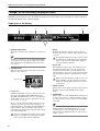 6
6
-
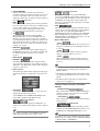 7
7
-
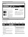 8
8
-
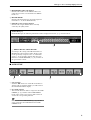 9
9
-
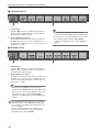 10
10
-
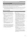 11
11
-
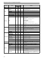 12
12
-
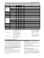 13
13
-
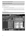 14
14
-
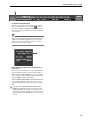 15
15
-
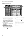 16
16
-
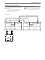 17
17
-
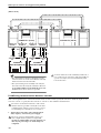 18
18
-
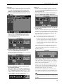 19
19
-
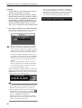 20
20
-
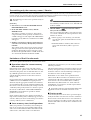 21
21
-
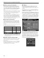 22
22
-
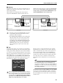 23
23
-
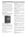 24
24
-
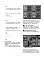 25
25
-
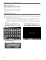 26
26
-
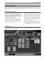 27
27
-
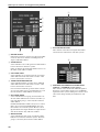 28
28
-
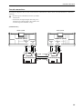 29
29
-
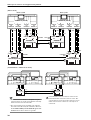 30
30
-
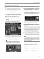 31
31
-
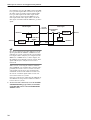 32
32
-
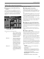 33
33
-
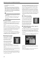 34
34
-
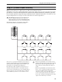 35
35
-
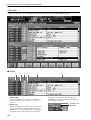 36
36
-
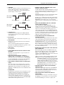 37
37
-
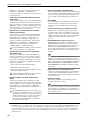 38
38
-
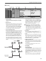 39
39
-
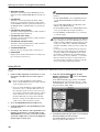 40
40
-
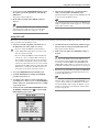 41
41
-
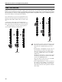 42
42
-
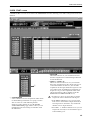 43
43
-
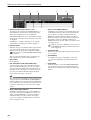 44
44
-
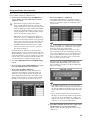 45
45
-
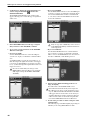 46
46
-
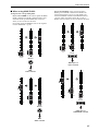 47
47
-
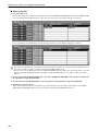 48
48
-
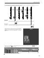 49
49
-
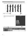 50
50
-
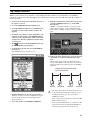 51
51
-
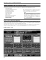 52
52
-
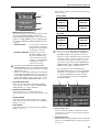 53
53
-
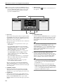 54
54
-
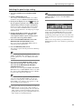 55
55
-
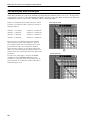 56
56
-
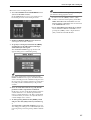 57
57
-
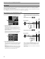 58
58
-
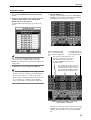 59
59
-
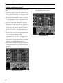 60
60
-
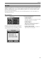 61
61
-
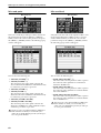 62
62
-
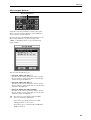 63
63
-
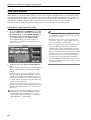 64
64
-
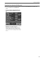 65
65
-
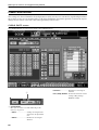 66
66
-
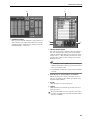 67
67
-
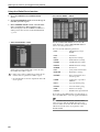 68
68
-
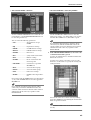 69
69
-
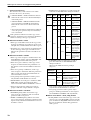 70
70
-
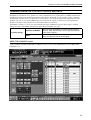 71
71
-
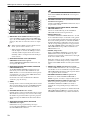 72
72
-
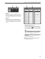 73
73
-
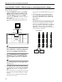 74
74
-
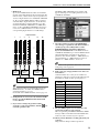 75
75
-
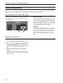 76
76
-
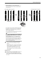 77
77
-
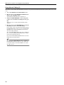 78
78
-
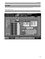 79
79
-
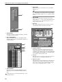 80
80
-
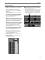 81
81
-
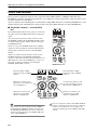 82
82
-
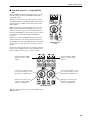 83
83
-
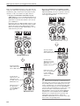 84
84
-
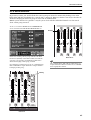 85
85
-
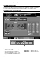 86
86
-
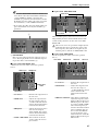 87
87
-
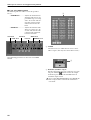 88
88
-
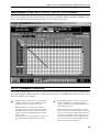 89
89
-
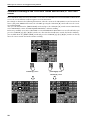 90
90
-
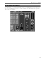 91
91
-
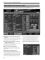 92
92
-
 93
93
-
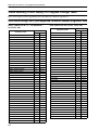 94
94
-
 95
95
-
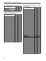 96
96
-
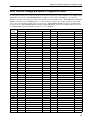 97
97
-
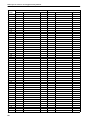 98
98
-
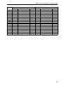 99
99
-
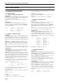 100
100
-
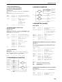 101
101
-
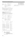 102
102
-
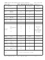 103
103
-
 104
104


Yamaha V1 Manual de usuario
- Categoría
- Mezcladores de audio
- Tipo
- Manual de usuario
- Este manual también es adecuado para
en otros idiomas
- français: Yamaha V1 Manuel utilisateur
- italiano: Yamaha V1 Manuale utente
- English: Yamaha V1 User manual
- Deutsch: Yamaha V1 Benutzerhandbuch
- русский: Yamaha V1 Руководство пользователя
- Nederlands: Yamaha V1 Handleiding
- português: Yamaha V1 Manual do usuário
- dansk: Yamaha V1 Brugermanual
- polski: Yamaha V1 Instrukcja obsługi
- čeština: Yamaha V1 Uživatelský manuál
- svenska: Yamaha V1 Användarmanual
- 日本語: Yamaha V1 ユーザーマニュアル
- Türkçe: Yamaha V1 Kullanım kılavuzu
- română: Yamaha V1 Manual de utilizare
Artículos relacionados
-
Yamaha V2 El manual del propietario
-
-
-
Yamaha CS1D El manual del propietario
-
-
-
-
-
-