
Page 1
MODELS QTXE050 • QTXE080 • QTXE110 • QTXE150
WARNING
TO REDUCE THE RISK OF FIRE, ELECTRIC SHOCK, OR IN-
JURY TO PERSONS, OBSERVE THE FOLLOWING:
1. Use this unit only in the manner intended by the manufacturer.
If you have questions, contact the manufacturer at the address
or telephone number listed in the warranty.
2. Before servicing or cleaning unit, switch power off at service
panel and lock the service disconnecting means to prevent
power from being switched on accidentally. When the ser-
vice disconnecting means cannot be locked, securely fasten
a prominent warning device, such as a tag, to the service
panel.
3. Installation work and electrical wiring must be done by a
standards.
-
ment to prevent backdrafting. Follow the heating equipment
manufacturer’s guideline and safety standards such as those
and the American Society for Heating, Refrigeration and Air
-
ties.
5. When cutting or drilling into wall or ceiling, do not damage
electrical wiring and other hidden utilities.
6. Ducted fans must always be vented to the outdoors.
7. Acceptable for use over a tub or shower when connected to
8. This unit must be grounded.
CAUTION
-
2. This product is designed for installation in ceilings up to a
DO NOT MOUNT THIS PRODUCT IN A WALL.
3. To avoid motor bearing damage and noisy and/or unbalanced
impellers, keep drywall spray, construction dust, etc. off power
unit.
-
tion and requirements.
QTXE SERIES
ULTRA SILENT
TM
FANS
READ AND SAVE THESE INSTRUCTIONS
CLEANING & MAINTENANCE
WARRANTY
Installer: Leave this manual with the homeowner.
-
ance - lower or remove grille and vacuum interior of unit with the
dusting brush attachment.
The motor is permanently lubricated and never needs oiling. If the
OPERATION
Use an on/off switch or speed control to operate this ventilator. See
“Connect Wiring” for details.
Use of speed controls other than the
Broan Models 78V and 78W may cause a motor humming noise.
To register this
product visit:
www.broan.com
BROAN THREE YEAR LIMITED WARRANTY
Broan warrants to the original consumer purchaser of its products that
such products will be free from defects in materials or workmanship for
a period of three years from the date of original purchase. THERE ARE
NO OTHER WARRANTIES, EXPRESS OR IMPLIED, INCLUDING, BUT
NOT LIMITED TO, IMPLIED WARRANTIES OF MERCHANTABILITY OR
FITNESS FOR A PARTICULAR PURPOSE.
During this three-year period, Broan will, at its option, repair or replace,
without charge, any product or part which is found to be defective under
normal use and service.
THIS WARRANTY DOES NOT EXTEND TO FLUORESCENT LAMP
-
installation instructions.
The duration of an implied warranty is limited to the three-year period as
on how long an implied warranty lasts, so the above limitation may not
apply to you.
BROAN’S OBLIGATION TO REPAIR OR REPLACE, AT BROAN’S OP-
TION, SHALL BE THE PURCHASER’S SOLE AND EXCLUSIVE REMEDY
UNDER THIS WARRANTY. BROAN SHALL NOT BE LIABLE FOR INCI-
DENTAL, CONSEQUENTIAL OR SPECIAL DAMAGES ARISING OUT OF
OR IN CONNECTION WITH PRODUCT USE OR PERFORMANCE. Some
damages, so the above limitation may not apply to you.
rights, which vary from state to state. This warranty supersedes all prior
warranties.
part. At the time of requesting warranty service, you must present evidence
of the original purchase date.
Broan-NuTone LLC Hartford, Wisconsin
www.broan.com 800-558-1711

Page 2
MODELS QTXE050 • QTXE080 • QTXE110 • QTXE150
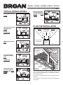
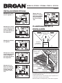
TYPICAL INSTALLATIONS
Housing mounted to
I-joists.
Housing mounted
anywhere between
trusses using hang-
er bars.
Housing mounted any-
where between
I-joists
using
hanger bars.
Housing mounted to
joists.
Housing mounted
anywhere between
joists
using
hanger bars.
Housing mounted
anywhere between
trusses using hang-
er bars.
PLAN THE INSTALLATION
where the shortest possible duct run and minimum number of
elbows will be needed.
Use a roof cap or wall cap that has a built-in damper to reduce
backdrafts.
Plan to supply the unit with proper line voltage and appropriate
power cable.
Cooking
Equipment
Floor
COOKING AREA
Do not install above or
inside this area.
45
o
45
o
NOT FOR USE IN
A COOKING AREA.
ROOF
CAP
*
6-IN. ROUND
*
6-IN.
ROUND
DUCT *
WALL
CAP
*
*
Purchase
separately
INSULATION
around and over
FAN
HOUSING

Page 3
MODELS QTXE050 • QTXE080 • QTXE110 • QTXE150
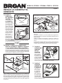
2. Attach
damper/duct
connector.
Snap damper /
duct connector
onto housing.
Make sure con-
top of housing and
closed.
3. Install
6-inch
round duct-
work.
Connect 6-inch
round ductwork
to damper / duct
connector. Run
ductwork to a
roof cap or wall
cap. Tape all
ductwork con-
nections to make
them secure and air tight.
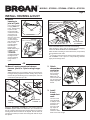
INSTALL HOUSING & DUCT
1a. Mount
housing to
joist or I-joist.
Use a pliers to bend
housing TABS out
to 90
0
. Hold housing
in place so that
the housing tabs
contact the bottom
housing mounts
or nails. Screw
or nail housing to
holes in each
then through
highest holes.
NOTE: Mounting to
I-JOIST
requires use
of SPACERS
the highest hole
of each mounting
I
SPACER
I-JOIST
TABS
1b. Mount housing anywhere between
trusses, joists, or I-joists using hanger
bars.
Sliding hanger bars are provided to allow for accurate posi-
tioning of housing anywhere between framing. They can be
I
Attach the MOUNTING CHANNELS to the housing using the
SCREWS supplied. Make sure TABS face “up” as shown. Use
the drywall.
OR
HANGER
TAB
HANGER BARS to the width of the framing.
Hold ventilator in place with the hanger bar tabs wrapping
around the BOTTOM EDGE OF THE FRAMING.
NAIL
through HOLES near nails.
* To ensure a noise-free mount: Secure hanger bars together
with SCREWS or use a pliers to crimp mounting channels
tightly around hanger bars.
HOLE FOR OPTIONAL
STD
MOUNTING
BOTTOM EDGE
OF FRAMING
*

Page 4
MODELS QTXE050 • QTXE080 • QTXE110 • QTXE150
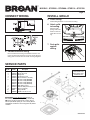
99044375A
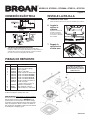
Order service parts by “Part No.” - not by “Key No.”
SERVICE NOTE To remove Blower Assembly: Unplug motor.
Remove thumbscrew (11) from motor plate flange. Find the single
TAB on the motor plate (located next to the receptacle). Push up
near motor plate tab while pushing out on side of housing. Or insert
a straight-blade screwdriver into slot in housing (next to tab) and twist
screwdriver.
Replacement parts
can be ordered on our
website. Please visit us
at www.broan.com
INSTALL GRILLE
6. Attach grille
to housing.
springs and insert
them into slots on
each side of hous-
ing.
7. Push grille
against
ceiling.
5. Finish ceiling.
Install ceiling material. Cut out around housing.
4. Connect electrical wiring.
Run 120 VAC house wiring to installation location. Use
proper UL approved connector to secure house wiring to
wiring plate. Connect wires as shown in wiring diagrams.
CONNECT WIRING
SERVICE PARTS
Key No. Part No. Description
1 97016466 Housing
2 97016450 Duct Connector-6”
3 98010102 Wiring Plate
4 99170245 Screw, #8-18 X .375
5 97018010 Wire Panel/Harness Assembly
6 97017782 Blower Assembly (QTXE050)
97017783 Blower Assembly (QTXE080)
97017784 Blower Assembly (QTXE110)
97016591 Blower Assembly (QTXE150)
7 99140199 Grille Spring (2 req’d)
8 97017621 Grille Assembly (includes key no. 7)
9 97018014 Spacer (2 supplied)
10 QTHB1 Hanger Bar Kit
11 99420665 Thumbscrew, #8-18 x .375

Página 5
MODELOS QTXE050 • QTXE080 • QTXE110 • QTXE150
ADVERTENCIA
PARA REDUCIR EL RIESGO DE INCENDIOS, DESCARGAS
ELÉCTRICAS O LESIONES PERSONALES, OBSERVE LAS
SIGUIENTES PRECAUCIONES:
1. Use la unidad sólo de la manera indicada por el fabricante. Si
tiene preguntas, comuníquese con el fabricante a la dirección
o al número telefónico que se incluyen en la garantía.
2. Antes de dar servicio a la unidad o de limpiarla, interrumpa el
suministro eléctrico en el panel de servicio y bloquee los me-
se reanude accidentalmente. Cuando no sea posible bloquear
lugar prominente del panel de servicio.
-
con todos los códigos y normas correspondientes, incluidos los
contra incendios.
-
bustión y descarga adecuadas de los gases a través del tubo
de seguridad del fabricante del equipo de calentamiento, tales
como las publicadas por la Asociación Nacional de Protección
la Sociedad Americana de Ingenieros de Calefacción, Refrig-
autoridades de los códigos locales.
5. Al cortar o perforar a través de la pared o del cielo raso, no
dañe el cableado eléctrico ni otros servicios ocultos.
6. Los ventiladores con conductos deben siempre conectarse
tina si se conecta a un circuito secundario protegido por un
8. Esta unidad debe conectarse a tierra.
PRECAUCIÓN
1. Sólo para usarlo en ventilación general. No lo use para des-
2. Este producto se diseña para la instalación en techos hasta
ESTE PRODUCTO EN UNA TECHO.
y/o no equilibrados, mantenga la unidad de accionamiento al
resguardo de rocío de yeso, polvo de la construcción, etc.
información y requisitos adicionales.
LEA Y CONSERVE ESTAS INSTRUCCIONES
LIMPIEZA Y MANTENIMIENTO
GARANTÍA
A la persona que realiza la instalación: Deje este manual con el dueño de la casa.
-
y aspire el interior de la unidad con el accesorio del cepillo para
sacudir polvo.
OPERACIÓN
Opere este ventilador mediante un interruptor de encendido/
apagado o control de velocidad de estado sólido. Vea los detalles
puede causar un ruido del tarareo del motor.
GARANTÍA LIMITADA DE TRES AÑOS DE BROAN
libres de defectos en cuanto a material y mano de obra durante un período de
tres años a partir de la fecha de la compra original. NO EXISTEN OTRAS GA-
GARANTÍAS IMPLÍCITAS DE COMERCIALIZACIÓN O IDONEIDAD PARA UN
PROPÓSITO PARTICULAR.
condiciones normales de uso y servicio.
ESTA GARANTÍA NO SE APLICA A ARRANCADORES NI A TUBOS DE LÁM-
instalación recomendadas.
La duración de una garantía implícita se limita al período de tres años, como
duración de una garantía implícita, de manera que las limitaciones antedichas
podrían no aplicarse a usted.
LA OBLIGACIÓN DE BROAN DE REPARAR O REEMPLAZAR, A OPCIÓN
DE BROAN, SERÁ EL ÚNICO Y EXCLUSIVO RECURSO DEL COMPRADOR
BAJO ESTA GARANTÍA. BROAN NO SERÁ RESPONSABLE POR DAÑOS
INCIDENTALES, RESULTANTES O ESPECIALES QUE SURJAN DE, O EN
RELACIÓN CON, EL USO O RENDIMIENTO DEL PRODUCTO. Algunos estados
posible que la limitación antedicha no se aplique en su caso.
derechos que varían entre estados. Esta garantía sustituye todas las garantías
anteriores.
debe presentar el comprobante con la fecha de la compra original.
Broan-NuTone LLC Hartford, Wisconsin
www.broan.com 800-558-1711
VENTILADORES
ULTRA SILENCIOSOS
SERIE QTXE
Para registrar este
producto visite:
www.broan.com

Página 6
MODELOS QTXE050 • QTXE080 • QTXE110 • QTXE150
INSTALACIONES TÍPICAS
PLANIFICACIÓN DE LA
INSTALACIÓN
Montaje de la cubi-
erta en viguetas “I”.
Montaje de la cu-
bierta en cualquier
parte entre armadu-
ras por medio de
barras de suspen-
sión.
Montaje de la cubier-
ta en cualquier parte
entre las viguetas “I”
por medio de barras
de suspensión.
Montaje de cubierta
en viguetas.
Montaje de la cubier-
ta en cualquier parte
entre las viguetas
por medio de barras
de suspensión.
Montaje de la cu-
bierta en cualquier
parte entre armadu-
ras por medio de
barras de suspen-
sión.
un mínimo número de codos.
Instale una tapa de techo o de pared que tenga un regulador de tiro
Equipo
para cocinar
Piso
ÁREA QUE COCINA
No instale sobre o dentro
de esta área.
45
o
45
o
NO PARA EL
USO EN UN
ÁREA QUE COCINA.
CODO REDONDO
DE 6 PULG. *
CUBIERTA DE
VENTILADOR
CONDUCTO
REDONDO DE
6 PULG. *
* Se compran
por separado
TAPA
DE
PARED*
TAPA DE
TECHO *
AISLAMIENTO
(Puede ser colocado
alrededor y sobre
de la cubierta del
ventilador.)

Página 7
MODELOS QTXE050 • QTXE080 • QTXE110 • QTXE150
O BIEN
INSTALE LA CUBIERTA Y EL
CONDUCTO
1a. Instale la
cubierta en
las viguetas o
viguetas “I”.
Con un alicate, doble
las LENGÜETAS
de la cubierta a 90°.
Sostenga la cubierta
en su lugar de manera
que las lengüetas
de la cubierta hagan
contacto con la parte
inferior de la vigueta.
o clavos. Atornille o
clave la cubierta a
la vigueta a través
y seguidamente a
altos. NOTA: Para el
VIGUETA “I”, tal como se ilustra, se requiere
SEPARADORES
1b. Instale la cubierta en cualquier parte
entre las armaduras, viguetas o viguetas
“I” por medio de barras de suspensión.
la colocación adecuada de la cubierta en cualquier parte entre la
estructura. Estas barras se adaptan a toda clase de estructuras
incluidos. Asegúrese de que las LENGÜETAS estén de cara hacia
la tablarroca.
VIGUETA “I”
SEPARADOR
LENGÜETA
BARRA DE SUS-
LENGÜETA
STD
CANAL DE
Abra las BARRAS DE SUSPENSIÓN hasta el ancho de la
estructura.
Sostenga el ventilador en su sitio envolviendo las lengüetas de
la barra de suspensión alrededor del BORDE INFERIOR DE LA
ESTRUCTURA.
clavos.
*
P
BORDE INFERIOR DE
LA ESTRUCTURA
2. Acople el
conector del
regulador
de tiro/
conducto.
Conecte a pre-
sión el conector
del regulador de
tiro/conducto en la
cubierta. Asegúrese
de que el conector
esté al ras con la
parte superior de la
cubierta y que la aleta del regulador caiga cerrada.
3. Instale el
conducto
redondo de
6 pulgadas.
Conecte el con-
ducto redondo
de 6 pulgadas
al conector del
regulador/con-
el conducto hacia
una tapa de techo
o tapa de pared.
hacerlas herméticas al aire.
ORIFICIO PARA MONTAJE
*

Página 8
MODELOS QTXE050 • QTXE080 • QTXE110 • QTXE150
PIEZAS DE REPUESTO
99044375A
Las piezas de recambio se
pueden ahora pedir en nuestro
Web site. Visítenos por favor en
www.broan.com
NOTA DE SERVICIO Para desmontar el conjunto del ventilador:
Desenchufe el motor. Saque el tornillo de mariposa (11) de la
brida de la placa del motor. Localice la LENGÜETA única de
la placa del motor (se encuentra junto al receptáculo). Empuje
hacia arriba cerca de la lengüeta de la placa del motor al mismo
tiempo que empuja hacia afuera el costado de la cubierta. O
bien, introduzca un destornillador de punta recta en la ranura de
la cubierta (junto a la lengüeta) y gírelo.
Al hacer el pedido de una pieza de servicio se debe especificar
el número de la pieza (no el número de la clave).
INSTALE LA REJILLA
6. Acople la
rejilla a la
cubierta.
Apriete los resortes de
en las ranuras que se
encuentran a cada lado
de la cubierta.
7. Empuje la
rejilla contra
el cielo raso.
5. Termine el cielo raso.
Instale el material del cielo raso. Recorte alrededor de la cubierta.
4. Conecte los cables eléctricos.
cableado de la casa a la placa de cableado. Conecte los cables
tal como se ilustra en los diagramas de cableado.
CONEXIÓN ELÉCTRICA
Clave n.
o
Pieza n.
o
Descripción
1 97016466 Cubierta
2 97016450 Conector del conducto (6 pulg.)
3 98010102 Placa de cableado
4 99170245 Tornillo n.
o
8-18 x 0.375
5 97018010 Conjunto del panel de cableado/arnés
6 97017782 Conjunto del ventilador (QTXE050)
97017783 Conjunto del ventilador (QTXE080)
97017784 Conjunto del ventilador (QTXE110)
97016591 Conjunto del ventilador (QTXE150)
7 99140199 Resorte de la rejilla (se requieren 2)
8 97017621 Conjunto de la rejilla
(incluye la pieza con clave n.
o
7)
9 97018014 Separador (se suministran 2)
10 QTHB1 Juego de barra de suspensión
11 99420665 Tornillo de mariposa n.
o
8-18 x 0.375
-
 1
1
-
 2
2
-
 3
3
-
 4
4
-
 5
5
-
 6
6
-
 7
7
-
 8
8


Broan QTXE110 Guía de instalación
- Tipo
- Guía de instalación
en otros idiomas
- English: Broan QTXE110 Installation guide
Artículos relacionados
-
Broan QTXE150 Guía de instalación
-
-
-
Broan QTXE110 Manual de usuario
-
-
-
-
-
Broan QTRE110 Guía de instalación
-