
INSTRUCTIONS FOR INSTALLATION AND MAINTENANCE (GB)
INSTRUCTIONS DE MISE EN SERVICE ET D'ENTRETIEN (FR)
INSTRUCCIONES PARA LA INSTALACIÓN Y EL MANTENIMIENTO (ES)
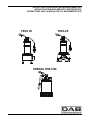
FEKA VS
FEKA VX
DRENAG 1000-1200


ENGLISH
1
CONTENTS
1. PUMPED FLUIDS ................................................................................................................................................................................................. 1
2. TECHNICAL DATA AND LIMITS ON USE ........................................................................................................................................................... 1
3. WARNINGS ........................................................................................................................................................................................................... 1
4. INSTALLATION .................................................................................................................................................................................................... 1
5. ELECTRIC CONNECTION .................................................................................................................................................................................... 2
6. CHECKING THE DIRECTION OF ROTATION (for three-phase motors) .......................................................................................................... 3
7. STARTING UP ...................................................................................................................................................................................................... 3
8. PRECAUTIONS ..................................................................................................................................................................................................... 3
9. MAINTENANCE AND CLEANING ........................................................................................................................................................................ 3
10. TROUBLESHOOTING ........................................................................................................................................................................................ 4
1. PUMPED FLUIDS
These pumps cannot be used in swimming pools, ponds or tanks in which people or present, or for pumping hydrocarbons
(petrol, diesel fuel, fuel oils, solvents, etc.) in accordance with the accident-prevention regulations in force.
N.B.: The liquid inside the pump, to lubricate the seal device, is not toxic but it may alter the characteristics of the water (if it is pure water) if
there is a leak in the seal device.
2. TECHNICAL DATA AND LIMITS ON USE
− Supply voltage:
1 X 115/127V 60Hz
1 X 220/230V 60Hz
3 X 220/277V 60Hz
see electric data plate
− Flow rate:
see electric data plate
− Hmax ( m ) - Head:
pag. 13
− Degree of motor protection / Protection class:
see electric data plate
− Absorbed power:
see electric data plate
− Liquid temperature range:
− from 32°F (0°C) to 95°F (+35°C) for domestic use (safety standards EN
60335-2-41)
− from 32°F (0°C) to 122°F (+50°C) for other uses
− Maximum immersion:
23 ft (7 metres)
− Storage temperature:
14°F 104°F (-10°C +40°C)
− Noise level:
Falls within the limits envisaged by EC Directive 89/392/EEC and subsequent modifications.
−
All single-phase models, except DRENAG are Cord & plug connected. DRENAG and all three phase models are permanently
connected to the supply connection.
−
Single phase models are supplied with or without a float activated level switch, identified by suffix “MA” (automatic) and “MNA”
(non-automatic).
Conditions of Acceptability:
1. All 3 phase models shall be protected against Running overload and stalled-rotor condition at the end use installation by a separate
overload protective device that is responsive to the motor current, as per the National Electrical Code (NEC) ANSI/NFPA 70-2011
and Canadian Electrical Code Part I
2. Products shall be installed in Accordance with the Local Code of the Authority Having Jurisdiction
Applicable requirements
CSA-C22.2 No. 108-14 (Reaffirmed 2019.)
- Liquid Pumps
UL Std. No. 778 6th Ed. (with revision through and including Aug. 11, 2020)
- Motor Operated Water Pumps
3. WARNINGS
– The tank is to be vented in accordance with local plumbing codes and shall warn the user that the pump is not to be installed in locations
classified as hazardous in accordance with the National Electrical Code, ANSI/NFPA 70.
– The installation permanently installed 3 phase pump shall state: "CAUTION" and the following or equivalent: "Risk of Electric Shock. Do not
remove cord and strain relief. Do not connect conduit to pump."
– For 3 phase models intended to be sold in Canada “USE WITH APPROVED MOTOR CONTROL THAT MATCHES MOTOR INPUT IN FULL
LOAD AMPERES WITH OVERLOAD ELEMENT(S) SELECTED OR ADJUSTED IN ACCORDANCE WITH CONTROL INSTRUCTIONS”
and “UTILISER UN DÉMARREUR APPROUVÉ CONVENANT AU COURANT À PLEINE CHARGE DU MOTEUR ET DONT LES ÉLÉMENTS
THERMIQUES SONT RÉGLÉS OU CHOISIS CONFORMÉMENT AUX INSTRUCTIONS QUI L'ACCOMPAGNENT”
– For single phase pumps supplied with cord & plug: “WARNING” and the following instructions or the equivalent: “Risk of electric shock –
This pump is supplied with a grounding conductor and grounding-type attachment plug. To reduce the risk of electric shock, be certain that
it is connected only to a properly grounded, grounding-type receptacle.”
– "CAUTION" and the following or equivalent: "This Pump Has Been Evaluated for Use With Water Only."
4. INSTALLATION
4.1
If the bottom of the well or borehole in which the pump is to operate is particularly dirty, it is advisable to provide a support for the pump to
sit on so as to avoid clogging of the intake grid (Fig.1, Fig.3)
4.2
Before putting the pump in position, ensure that the strainer is not totally or partially blocked by mud, sediment or similar substances.

ENGLISH
2
4.3
It is advisable to use pipes with an internal diameter at least equal to that of the delivery mouth, to avoid falls in pump performance and
the possibility of clogging. In cases where the delivery pipe has long horizontal stretches, it is advisable for this pipe t
o have a larger
diameter than that of the delivery mouth.
Totally immerse the pump in the water.
INSTALLATION FEKA VS-VX
4.4
On the version provided with a float switch, ensure that the float can move freely (SEE THE PARAGRAPH ON ADJUSTING THE FLOAT
SWITCH). Ensure that the minimum dimensions of the borehole are as in Fig.1. The dimensions of the borehole must also be calculated
with relation to the quantity of water arriving and to the pump flow rate so as not to subject the motor to excessive starting operations.
4.5
When the pump is to be in a fixed installation, with a float, a check valve must always be fitted in the delivery pipe. This is also advisable
on pumps with manual operation.
4.6
Connect the delivery pipe or hose directly to the pump mouth. If the pump is used in fixed installations it is advisable to connect it to the
pipe with a coupling so as to facilitate disassembly and reinstallation. If a hose is used, fit a threaded hosetail on the pump mouth. Wrap
the thread with suitable material to ensure an effective seal (teflon tape or similar).
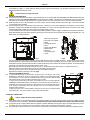
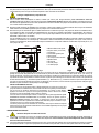
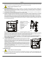
For fixed installations we advise the use of the lifting device DSD2 (available on request - Fig.2) to facilitate pump maintenance operations.
When fitted between the pump delivery aperture and the pipe, it avoids having to remove the delivery pipe during maintenance jobs. The
DSD2 device is composed of 8 parts:
A.Pipe anchoring bracket
B.3/4" pipes (not supplied)
C.Slide.
D.Pipe guide columns
E.Foot
F.Screw TCEI M10X25
G.Base bracket
H.Nut M10
I.Pump flange screw
L.Pump
The foot is positioned on the bottom of the tank and fixed with expansion screws of suitable dimensions. The pipe guide bracket must be
positioned at the top of well or borehole and inserted in the end of two 3/4” pipes (not supplied), which act as a slide. The two pipes connect
the bracket to the foot. Position the base bracket in contact with the pump suction strainer near the delivery aperture, secure everything to
the strainer cover with the screws provaided to lock the strainer cover.
Remove the top screw from the flange on the delivery side ( I ). Assemble the anti-rotation bracket ( G ). Replace the screw ( I ).
Extract the slide from the coupling foot and connect it to the delivery port of the pump.
Using the screw F and the nut H, fix the slide to the pump as indicated in the figure.
Reposition the slide/pump assembly on the foot (Fig.2).
4.7
INSTALLATION DRENAG 1000-1200
1. Connect the delivery pipe or hose directly to the pump mouth. If the pump is used in fixed
installations it is advisable to connect it to the pipe with a coupling so as to facilitate disassembly
and reinstallation. If a hose is used, fit a threaded hosetail on the pump mouth. Wrap the thread
with suitable material to ensure an effective seal (teflon tape or similar).
2. On the version provided with a float switch, ensure that the float can move freely (SEE THE
PARAGRAPH ON ADJUSTING THE FLOAT SWITCH). Ensure that the minimum dimensions of
the borehole are as in Fig.3. The dimensions of the borehole must also be calculated with relation
to the quantity of water arriving and to the pump flow rate so as not to subject the motor to
excessive starting operations.
3. When the pump is to be in a fixed installation, with a float, a check valve must always be fitted
in the delivery pipe. This is also advisable on pumps with manual operation.
5. ELECTRIC CONNECTION
Caution: always follow the safety regulations!
5.1
Single-phase motors are provided with built-in thermal overload protection and may be connected directly to the mains. N.B. If the motor
is overloaded it stops automatically. Once it has cooled down it starts again automatically without any need for manual intervention.
5.2
Three-phase pumps must be protected with motor protectors suitably calibrated according to the values on the data plate of the pump to
be installed. The plug on the pump must be connected to an EEC socket complete with isolating switch and fuses.
5.3
Do not damage or cut the power cable. If this should occur accidentally, have it repaired or replaced by skilled and qualified personnel.
HIA
G
C
F
B
D
E
L
700x700
ON
OFF
Fig.1
Fig.2
Fig.3
600x600
ON
OFF

ENGLISH
3
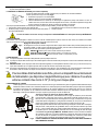
6. CHECKING THE DIRECTION OF ROTATION (for three-phase motors)
The direction of rotation must be checked each time a new installation is made.
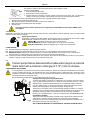
Proceed as follows (Fig.4):
1. Place the pump on a flat surface.
2. Start the pump and stop it immediately.
3. Carefully observe the kick-back on starting, looking at the pump
from the motor side. The direction of
rotation is correct, that is clockwise, if the protection cap moves as in the drawing (anti-clockwise).
If it is not possible to check as described above because the pump is already installed, check as follows:
1. Start the pump and observe the water flow rate.
2. Stop the pump, switch off the power and invert two phases on the supply line.
3. Restart the pump and check the water flow rate again.
4. Stop the pump.
The correct direction of rotation will be the one corresponding to the HIGHEST flow rate and the LOWEST power
consumption!
7. STARTING UP
Models with a float switch start up automatically when the water level rises; models without a float are started by means of a switch located
upstream from the socket (not supplied).
Adjusting the float switch
Lengthening or shortening the cable between the float and the fixed point (slot provided in the handle - Fig.5)
adjusts the START or STOP level of the pump. Be sure that the float can move freely.
DRENAG
Ensure that the stop level does not uncover the strainer.
FEKA VS-VX 550-750 Minimum stopping level 1.21 ft (370 mm) from the bottom.
FEKA VS-VX 1000-1200 Minimum stopping level 1.31 ft (400 mm) from the bottom.
8. PRECAUTIONS
8.1
The intake strainer must always be in place during pump operation.
8.2
The pump should not be started more than 20 times in one hour so as not to subject the motor to excessive thermal shock.
8.3
DANGER OF FROST: When the pump remains inactive for a long time at temperatures of less than 32°F (0°C), it is necessary to
ensure that there is no water residue which could freeze and cause cracking of the pump components.
8.4
If the pump has been used with substances which tend to form a deposit, rinse it after use with a powerful jet of water so as to avoid the
formation of deposits or scale which would tend to reduce the yield of the pump.
8.5
Connect pumps that are delivered without cable and/or plugs to an external
mains switch with a minimum contact gap of 0.12" (3 mm) in all poles.
9. MAINTENANCE AND CLEANING
In normal operation, the pump does not require any specific maintenance, thanks to its mechanical seal lubricated in an oil chamber
and to its sealed-for-life bearings. The electropump must not be dismantled unless by skilled personnel in possession of the
qualifications required by the regulations in force. In any case, all repairs and maintenance jobs must be carried out only after having
disconnected the pump from the power mains.
During disassembly, pay attention to any sharp parts which could cause injury.
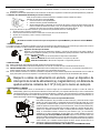
Checking and changing the sealing oil FEKA VS-VX
To perform this operation, slacken the six screws (45) so as to be able to remove the strainer
cover , the strainer and the pump body (1). Retain the O-ring (28) and the nuts (51). Using a
suitable spanner, unscrew the impeller retaining nut (18), holding the impeller (4) still with
your hand. Retain the key (17) and the sand guard (15). Now overturn the pump with the
hydraulic part facing upwards, unscrew and remove the drainage cap (64).
Tilt the pump so as to let the oil flow out of the drainage hole (64) and catch it in a container.
Analyse the oil: if you find any particles of water or abrasive materials (for example, sand) it is
advisable to check the condition of the mechanical seal (16) and to have it changed if
necessary (at a specialized centre). In this case change the oil too, with about 170 gr of oil
type MARCOL 152 ESSO.
Top up the oil level inside the sealing oil chamber using a special funnel inserted in the hole
in the cap (64). Screw the drainage cap (64) back on and perform the disassembly
operations in inverse order to reassemble the pump after having spread a suitable amount of
teflon grease in the seat of the sand guard (15).
OLD OIL MUST BE DISPOSED OF AS REQUIRED BY THE REGULATIONS IN FORCE.
Fig.4
Fig.5
18 17 15
1
4
45
64
16
Fig.6

ENGLISH
4
Checking and changing the sealing oil DRENAG 1000-1200
To perform this operation you must unscrew the six screws of the flange (45) so as to be able
to remove the flange (105) and the outer jacket (77). Unscrew the three screws of the filter
cover (136) and remove the cover (92) and the filter (42). Unscrew the four screws of the
pump body (52) and remove the pump body (1). Using a suitable wrench, unscrew the nut
(18) that blocks the impeller, holding the impeller (4) still with your hand. Remove the impeller
(4), if necessary with the aid of levers. Recover the tab (17) and the sand protection ring (15),
unscrew and remove the cap (64). Tilt the pump so as to drain the oil out of the hole of the
cap (64) and pour it into a container. Analyse the oil: if you find any particles of water or
abrasive materials (for example, sand) it is advisable to check the condition of the mechanical
seal (16) and to have it changed if necessary (at a specialized centre). In this case change
the oil too, with about 170 gr of oil type MARCOL 152 ESSO.
Top up the oil level inside the sealing oil chamber using a special funnel inserted in the hole
in the cap (64). Screw the drainage cap (64) back on and perform the disassembly
operations in inverse order to reassemble the pump after having spread a suitable amount of
teflon grease in the seat of the sand guard (15).
Attention! During assembly, fit all the O-rings correctly, without damaging them.
OLD OIL MUST BE DISPOSED OF AS REQUIRED BY THE REGULATIONS IN FORCE.
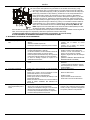
10. TROUBLESHOOTING
FAULT
CHECK (possible cause)
REMEDY
1. The motor does not start and
makes no noise.
A. Check that the motor is live.
B. Check the protection fuses.
C. The float switch does not allow starting.
B. If they are burnt-out, change them.
C. -Ensure that the float moves freely.
-Ensure that the float is
efficient (contact the
supplier).
2. The pump does not deliver.
A. The intake grid or the pipes are blocked.
B. The impeller is worn or blocked.
C. The check valve, if installed on the delivery pipe, is
blocked in closed position.
D. The level of the liquid is too low. When starting, the
level of the liquid must be higher than that of the
strainer.
E.
The required head is higher than the pump
characteristics.
A. Remove the blockage.
B. Change the impeller or remove the blockage.
C. Check that the valve is operating correctly and
replace it if necessary.
D.
Adjust the length of the float switch cable
(SEE THE PARAGRAPH ON "ADJUSTING
THE FLOAT SWITCH").
3. The pump does not stop.
A. The switch is not disactivated by the float.
A. -Ensure that the float moves freely.
B. -Check float efficiency (the contacts could be
damaged - contact the supplier).
4. The flow is insufficient.
A. Ensure that the intake grid is not partly blocked.
B. Ensure that the impeller or the delivery pipe are not
partly blocked or encrusted.
C. Ensure that the impeller is not worn.
D.
Ensure that the check valve (if fitted) is not partly
clogged.
E. On three-
phase motors, check that the direction of
rotation is correct (See the paragraph on
"CHECKING THE DIRECTION OF ROTATION").
A. Remove any blockage.
B. Remove any blockage.
C. Change the impeller.
D. Carefully clean the check valve.
E. Invert the connection of two supply wires.
5. The thermal overload
protection stops the pump.
A. Check that the liquid to be pumped is not too dense
as this could cause overheating of the motor.
B. Check that the water temperature is not too high.
C. The pump is partly blocked by impurities.
D. The pump is mechanically blocked.
C. Carefully clean the pump.
D.
Check whether there is rubbing between the
moving and fixed parts; check the wear of the
bearings (contact the supplier).
18 17 15
92
64
16
Fig.7

FRANÇAIS
5
CONTENTS
1. LIQUIDES POMPES ............................................................................................................................................................................................. 5
2. CARACTERISTIQUES TECHNIQUES ET LIMITES D'UTILISATION ................................................................................................................. 5
3. AVERTISSEMENTS .............................................................................................................................................................................................. 5
4. INSTALLATION .................................................................................................................................................................................................... 5
5. BRANCHEMENT ELECTRIQUE .......................................................................................................................................................................... 6
6. CONTROLE DU SENS DE ROTATION (pour moteurs triphasés) .................................................................................................................... 7
7. MISE EN MARCHE ............................................................................................................................................................................................... 7
8. PRECAUTIONS ..................................................................................................................................................................................................... 7
9. MAINTENANCE ET LAVAGE ............................................................................................................................................................................... 7
10. IDENTIFICATION DES INCONVENIENTS ET REMEDES ................................................................................................................................. 8
1. LIQUIDES POMPES
Ces pompes ne peuvent pas être utilisées dans des piscines, des étangs, des bassins avec des personnes présentes dans
l'eau ou pour le pompage d'hydrocarbures (essence, gasoil, huiles combustibles, solvants etc.) conformément aux normes
en vigueur pour la prévention des accidents.
N.B.: Le liquide contenu dans la pompe, pour lubrifier la garniture d'étanchéité, n'est pas toxique mais peut altérer les caractéristiques de l'eau
(en cas d'eau pure) si la garniture présente des fuites.
2. CARACTERISTIQUES TECHNIQUES ET LIMITES D'UTILISATION
− Tension d'alimentation:
1 X 115/127V 60Hz
1 X 220/230V 60Hz
3 X 220/277V 60Hz
Voir plaquettes données
électriques
− Débit:
Voir plaquettes données électriques
− Hmax ( m ) - Hauteur manométrique:
pag. 13
− Degré de protection moteur / Classe de protection / Puissance absorbée:
Voir plaquettes données électriques
− Plage de température du liquide:
− de 32°F (0°C) à 95°F (+35°C) pour l'usage domestique (normes de sécurité
EN 60335-2-41)
− de 32°F (0°C) à 122°F (+50°C) pour autres utilisations
− Immersion maximum:
23 ft (7 mètres)
− Température de stockage:
14°F 104°F (-10°C +40°C)
− Niveau de bruit:
le niveau de bruit rentre dans les limites prévues par la directive EC 89/392/CEE et modifications successives.
−
All single-phase models, except DRENAG are Cord & plug connected. DRENAG and all three phase models are permanently
connected to the supply connection.
−
Single phase models are supplied with or without a float activated level switch, identified by suffix “MA” (automatic) and “MNA”
(non-automatic).
Conditions of Acceptability:
1. All 3 phase models shall be protected against Running overload and stalled-rotor condition at the end use installation by a separate
overload protective device that is responsive to the motor current, as per the National Electrical Code (NEC) ANSI/NFPA 70-2011
and Canadian Electrical Code Part I
2. Products shall be installed in Accordance with the Local Code of the Authority Having Jurisdiction
Applicable requirements
CSA-C22.2 No. 108-14 (Reaffirmed 2019.)
- Liquid Pumps
UL Std. No. 778 6th Ed. (with revision through and including Aug. 11, 2020)
- Motor Operated Water Pumps
3. AVERTISSEMENTS
– The tank is to be vented in accordance with local plumbing codes and shall warn the user that the pump is not to be installed in locations
classified as hazardous in accordance with the National Electrical Code, ANSI/NFPA 70.
– The installation permanently installed 3 phase pump shall state: "CAUTION" and the following or equivalent: "Risk of Electric Shock. Do not
remove cord and strain relief. Do not connect conduit to pump."
– For 3 phase models intended to be sold in Canada “USE WITH APPROVED MOTOR CONTROL THAT MATCHES MOTOR INPUT IN
FULL LOAD AMPERES WITH OVERLOAD ELEMENT(S) SELECTED OR ADJUSTED IN ACCORDANCE WITH CONTROL
INSTRUCTIONS” and “UTILISER UN DÉMARREUR APPROUVÉ CONVENANT AU COURANT À PLEINE CHARGE DU MOTEUR ET
DONT LES ÉLÉMENTS THERMIQUES SONT RÉGLÉS OU CHOISIS CONFORMÉMENT AUX INSTRUCTIONS QUI
L'ACCOMPAGNENT”
– For single phase pumps supplied with cord & plug: “WARNING” and the following instructions or the equivalent: “Risk of electric shock –
This pump is supplied with a grounding conductor and grounding-type attachment plug. To reduce the risk of electric shock, be certain that
it is connected only to a properly grounded, grounding-type receptacle.”
– "CAUTION" and the following or equivalent: "This Pump Has Been Evaluated for Use With Water Only."
4. INSTALLATION
4.1
Si le fond du puits où la pompe doit fonctionner est particulièrement sale, il est bon de prévoir un support pour poser la pompe afin d'éviter
que la crépine d'aspiration se bouche (Fig.1, Fig.3)
4.2
Avant de positionner la pompe, s'assurer que la crépine n'est pas totalement ou partiellement bouchée par la boue, les sédiments ou autres.

FRANÇAIS
6
4.3
Il est conseillé d'utiliser des tuyauteries ayant un diamètre interne égal au moins à celui de la bride de refoulement, pour éviter la diminution
des performances de la pompe et le risque d'obstructions. Si le tuyau de refoulement parcourt des distances considérables à l'horizontale,
il est conseillé de prévoir un tuyau de diamètre supérieur à celui de la bride de refoulement.
Immerger complètement la pompe dans l'eau.
INSTALLATION FEKA VS-VX
4.4
Pour la version munie d'interrupteur à flotteur, contrôler que celui-ci peut bouger librement (VOIR PARAGRAPHE REGLAGE
INTERRUPTEUR A FLOTTEUR). Prévoir des puisards ayant les dimensions minimum indiquées dans la Fig.1. Le puisard devra toujours
être dimensionné également en fonction de la quantité d'eau en arrivée et du débit de la pompe de manière à ne pas soumettre le moteur
à un nombre excessif de démarrages.
4.5
Quand la pompe est prévue en installation fixe, avec flotteur, il faut toujours installer un clapet de retenue dans le tuyau de refoulement.
Cette exécution est conseillable également pour les pompes avec fonctionnement manuel.
4.6
Raccorder le tuyau de refoulement rigide ou flexible directement sur la bride de la pompe. Si la pompe est utilisée en installations fixes, il
est conseillé de la relier à la tuyauterie par l'intermédiaire d'un raccord pour en faciliter le démontage et la réinstallation. Si on utilise un
tuyau flexible, appliquer sur la bride de la pompe un raccord porte-
tuyau fileté.Garnir le filet avec du matériau approprié pour assurer
l'étanchéité (ruban en teflon ou similaire).
Pour les installations fixes nous conseillons l’utilisation d’un dispositif de levage DSD2 (disponible sur demande - Fig.2) pour faciliter les
opérations de maintenance sur l’électropompe. Inséré entre la bride de refoulement de l’électropompe et le tuyau, il évite, d
ans les
opérations de maintenance, de devoir démonter le tuyau de refoulement. Le dispositif DSD2 est constitué de 8 composants plus un, non
fourni (tuyaux de 3/4”):
A.Bride de fixation des tuyaux
B.Tuyaux de 3/4” (non fournis)
C.Coulisseau
D.Colonnettes guide-tuyaux
E.Pied d’assise
F.Vis à 6 pans creux M10X25
G.Bride de base
H.Écrou M10
I.Vis bride pompe
L.Vis bride pompe
Le pied d’assise doit être positionné dans le fond de la cuve et fixé avec des vis tamponnées correctement dimensionnées. La bride de
guidage du tuyau doit être positionnée sur la partie haute du puisard et insérée à l’extrémité des deux tuyaux de 3/4” (non founis), qui
servent de descente. Les deux tuyaux relient la bride au pied d’assise. Positionner la bride de base en contact avec le filtre de la pompe,
à proximité de l’orifice de refoulement, en fixant avec deux vis prévues pour le blocage du couvercle du filtre. Enlever la vis supérieure de
la bride côté refoulement ( I ). Assembler la patte antirotation ( G ). Remonter la vis ( I ). Extraire la coulisse du pied d’accouplement et la
raccorder à l’orifice de refoulemtent de la pompe. En utilisant la vis F et l’écrou H, fixer la coulisse à la pompe comme l’indique la figure.
Remettre en place l’ensemble coulisse/pompe sur le pied (Fig.2)
INSTALLATION DRENAG 1000-1200
4.7
1. Raccorder le tuyau de refoulement rigide ou flexible directement sur la bride de la pompe. Si la
pompe est utilisée en installations fixes, il est conseillé de la relier à la tuyauterie par l'intermédiaire
d'un raccord pour en faciliter le démontage et la réinstallation. Si on utilise un tuyau flexible,
appliquer sur la bride de la pompe un raccord porte-tuyau fileté. Garnir le filet avec du matériau
approprié pour assurer l'étanchéité (ruban en teflon ou similaire).
2. Pour la version munie d'interrupteur à flotteur, contrôler que celui-ci peut bouger librement (VOIR
PARAGRAPHE REGLAGE INTERRUPTEUR A FLOTTEUR). Prévoir des puisards ayant les
dimensions minimum indiquées dans la Fig.3. Le puisard devra toujours être dimensionné
également en fonction de la quantité d'eau en arrivée et du débit de la pompe de manière à ne pas
soumettre le moteur à un nombre excessif de démarrages.
3. Quand la pompe est prévue en installation fixe, avec flotteur, il faut toujours installer un clapet de
retenue dans le tuyau de refoulement. Cette exécution est conseillable également pour les pompes
avec fonctionnement manuel.
5. BRANCHEMENT ELECTRIQUE
Attention: Respecter les normes de securite!
5.1
Les moteurs monophasés sont munis de protection thermique ampèremétrique incorporée et peuvent être raccordés directement au
secteur. N.B.: si le moteur est surchargé, il s'arrête automatiquement. Une fois refroidi, il repart automatiquement sans avoir besoin
d'aucune intervention manuelle.
5.2
Les pompes triphasées doivent être protégées par des coupe-circuits appropriés calibrés selon les caractéristiques indiquées sur la plaque
de la pompe à installer. La prise de la pompe doit être connectée à une prise CEE munie d’un interrupteur sectionneur et de fusibles.
HIA
G
C
F
B
D
E
L
700x700
ON
OFF
Fig.1
Fig.2
Fig.3
600x600
ON
OFF

FRANÇAIS
7
5.3
Ne pas endommager ou couper le câble d'alimentation. Si cela se produit, pour la réparation ou le remplacement du câble, faire appel à
du personnel spécialisé et qualifié.
6. CONTROLE DU SENS DE ROTATION (pour moteurs triphasés)
Le sens de rotation devra être contrôlé à chaque fois qu'on effectue une nouvelle installation.
Il faudra procéder de la façon suivante (Fig.4):
1. Positionner la pompe sur une surface plate.
2. Mettre la pompe en marche et l'arrêter immédiatement.
3.
Observer attentivement le contrecoup au démarrage en regardant la pompe côté moteur. Le sens de
rotation est correct, à savoir dans le sens des aiguilles d'une montre, si la calotte de protection bouge dans
le sens indiqué par les flèches du dessin (contraire aux aiguilles d'une montre).
S'il n'est pas possible d'effectuer ce contrôle parce que la pompe est déjà installée, procéder de la façon suivante:
1. Faire partir la pompe et observer le débit de l'eau.
2. Arrêter la pompe, couper la tension et intervertir deux des phases
de la ligne d'alimentation.
3. Remettre la pompe en marche et contrôler de nouveau le débit.
4. Arrêter la pompe.
Le sens de rotation correct sera celui qui correspond au débit SUPÉRIEUR et à l’absorption électrique INFÉRIEURE!
7. MISE EN MARCHE
Les modèles munis d'interrupteur à flotteur sont mis en marche automatiquement quand le niveau de l'eau monte; les modèles sans flotteur
sont mis en marche au moyen d'un interrupteur situé en amont de la prise (non fourni).
Reglage de l'interrupteur a flotteur
En allongeant ou en raccourcissant le segment de câble compris entre le flotteur et le point fixe (bride prévue dans
la poignée - Fig.5), on règle le niveau d'enclenchement (START) ou/et le niveau de déclenchement (STOP) de la
pompe. Faire en sorte que le flotteur puisse bouger librement.
DRENAG
Vérifier que le niveau d'arrêt ne découvre pas le filtre.
FEKA VS-VX 550-750
Niveau minimum d’arrêt 1.21 ft (370 mm) du fond.
FEKA VS-VX 1000-1200 Niveau minimum d’arrêt 1.31 ft (400 mm) du fond.
8. PRECAUTIONS
8.1
La crépine d'aspiration doit toujours être présente quand la pompe fonctionne.
8.2
La pompe ne doit pas être soumise à plus de 20 démarrages horaires de manière à ne pas exposer le moteur à des sollicitations thermiques
excessives.
8.3
DANGER DE GEL: quand la pompe reste inactive pendant longtemps à une température inférieure à 32°F (0°C), il faut s'assurer qu'il n'y
a pas d'eau résiduelle qui en congelant pourrait créer des fissures dans les composants de la pompe.
8.4
Si la pompe a été utilisée avec des substances qui ont tendance à se déposer, rincer l'installation avec un puissant jet d'eau, après l'emploi,
de manière à éviter la formation de dépôts ou d'incrustations qui tendraient à réduire les caractéristiques de la pompe.
8.5
Pour les câbles d’alimentation sans fiche, prévoir un dispositif de sectionnement
de l’alimentation (ex disjoncteur magnétothermique) avec distance d’ouverture
entre les contacts d’au moins 0.12" (3 mm) pour chaque pôle.
9. MAINTENANCE ET LAVAGE
L'électropompe, lors du fonctionnement normal, n'a besoin d'aucun type de maintenance grâce à la garniture d'étanchéité mécanique
lubrifiée en chambre à huile et aux roulements lubrifiés à vie. L'électropompe ne peut être démontée que par du personnel spécialisé
et qualifié en possession des caractéristiques requises par les normes spécifiques en la matière. Dans tous les cas, toutes les
interventions de réparation et de maintenance doivent être effectuées seulement après avoir débranché la po
mpe. Durant le
démontage, il faut faire très attention aux corps coupants qui peuvent provoquer des blessures.
Controle et vidange de l'huile de la garniture FEKA VS-VX
Pour effectuer cette opération, il faut dévisser les six vis (45) de manière à pouvoir démonter
le couvercle filtre, le filtre et le corps pompe (1). Récupérer le joint OR (28) et les écrous (51).
Dévisser avec une clé spéciale l'écrou de blocage de la roue (18), en bloquant la roue (4) avec
la main. Récupérer la languette (17) et la garniture anti-sable (15). A ce point, en renversant la
pompe avec la partie hydraulique vers le haut, dévisser et enlever le bouchon (64).
Incliner la pompe de manière à faire sortir l'huile par le goulot (64) et la verser dans un récipient.
Analyser l'huile: si elle présente des gouttelettes d'eau ou des particules abrasives (du sable
par ex.), il faut contrôler l'état de la garniture d'étanchéité mécanique (16) et la remplacer le
cas échéant (dans un centre spécialisé). Effectuer dans ce cas la vidange de l'huile et remplir
avec environ 170 g d'huile type MARCOL 152 ESSO. Rétablir le niveau de l'huile à l'intérieur
de la chambre à huile avec un entonnoir enfilé dans le goulot (64). Revisser le bouchon (64) à
sa place et effectuer les opérations
inverses au démontage pour remonter la pompe après
avoir appliqué dans le logement de la bague anti-sable (15) de la graisse au teflon.
L'HUILE USAGEE DOIT ETRE RECUPEREE POUR LE RECYCLAGE DANS LE RESPECT
DES NORMES EN VIGUEUR.
Fig.4
Fig.5
18 17 15
1
4
45
64
16
Fig.6

FRANÇAIS
8
Controle et vidange de l'huile de la garniture DRENAG 1000-1200
Pour effectuer cette opération il faut dévisser les six vis de la bride (45) de manière à pouvoir
enlever la bride (105) et la chemise externe (77).<0} {0>Svitare le tre viti del coperchio filtro
(136) e rimuovere il coperchio (92) e il filtro (42).<}0{>Dévisser les trois vis du couvercle filtre
(136) et enlever le couvercle (92) et le filtre (42).<0} {0>Svitare le quattro viti del corpo pompa
(52) e rimuovere il corpo pompa (1).<}0{>Dévisser les quatre vis du corps pompe (52) et
enlever le corps pompe (1).<0} {0>Svitare con un’apposita chiave il dado bloccaggio girante
(18), tenendo bloccata a mano la girante (4).<}0{>Dévisser avec une clé spéciale l’écrou de
blocage de la roue (18), tout en bloquant la roue avec la main (4).<0} {0>Rimuovere la girante
(4) aiutandosi con delle leve se necessario.<}0{>Enlever la roue (4) en utilisant des leviers si
nécessaire.<0} {0>Recuperare la linguetta (17) e l’anello parasabbia (15), svitare e togliere il
tappo (64).<}0{>Récupérer la clavette (17) et la garniture antisable (15), dévisser et enlever le
bouchon (64).<0} {0>Inclinare la pompa in modo da far uscire l’olio dal foro del tappo (64) e
versarlo in un recipiente.<}0{>Incliner la pompe de manière à faire sortir l’huile par le trou du
bouchon (64) et la verser dans un récipient Analyser l'huile: si elle présente des gouttelettes
d'eau ou des particules abrasives (du sable par ex.), il faut contrôler l'état de la garniture
d'étanchéité mécanique (16) et la remplacer le cas échéant (dans un centre spécialisé).
Effectuer dans ce cas la vidange de l'huile et remplir avec environ 170 g d'huile type
MARCOL 152 ESSO.
Rétablir le niveau de l'huile à l'intérieur de la chambre à huile avec un entonnoir enfilé dans le
goulot (64).
Revisser le bouchon (64) à sa place et effectuer les opérations inverses au démontage pour remonter la pompe après avoir appliqué dans le
logement de la bague anti-sable (15) de la graisse au teflon.
Attention ! Lors du montage, mettre correctement en place tous les joints toriques, sans les abîmer.
L'HUILE USAGEE DOIT ETRE RECUPEREE POUR LE RECYCLAGE DANS LE RESPECT DES NORMES EN VIGUEUR.
10. IDENTIFICATION DES INCONVENIENTS ET REMEDES
INCONVENIENTS
CONTROLES (causes possibles)
REMEDES
1. Le moteur ne démarre pas
et ne fait pas de bruit.
A. Vérifier que le moteur est sous tension.
B. Vérifier les fusibles de protection.
C. L'interrupteur à flotteur ne permet pas le démarrage.
B. S'ils sont grillés, les remplacer.
C. - Vérifier que le flotteur bouge librement.
- Vérifier que le flotteur fonctionne (contacter le
fournisseur).
2. La pompe ne refoule pas.
A. La crépine d'aspiration ou les tuyaux sont bouchés.
B. La roue est usée ou bouchée.
C.
Le clapet de retenue s'il est installé sur le tuyau de
refoulement est bloqué en position fermée.
D. Le niveau du liquide est trop bas. Au démarrage, le niveau
de l'eau doit être supérieur à celui de la crépine.
E.
La hauteur manométrique est supérieure aux
caractéristiques de la pompe.
A. Eliminer les obstructions.
B. Remplacer la roue ou éliminer l'obstruction.
C. Contrôler le bon fonctionnement du clapet et le
remplacer éventuellement.
D.
Régler la longueur du câble de l'interrupteur à
flotteur (voir paragraphe "REGLAGE DE
L'INTERRUPTEUR A FLOTTEUR").
3. La pompe ne s'arrête pas.
A. Le flotteur n'interrompt pas le fonctionnement de la
pompe.
A. -Vérifier que le flotteur bouge librement.
-Vérifier l'efficacité du flotteur (les contacts
pourraient être endommagés - contacter le
fournisseur).
4. Le débit est insuffisant.
A. Vérifier que la crépine d'aspiration n'est pas partiellement
bouchée.
B.
Vérifier qu'il n'y a pas d'obstructions partielles ou
d'incrustations sur la roue ou dans le tuyau de refoulement.
C. Vérifier que la roue n'est pas usée.
D. Vérifier que le clap
et de retenue (s'il est prévu) n'est pas
partiellement bouché.
E.
Vérifier le sens de rotation dans les versions triphasées
(voir paragraphe "CONTROLE DU SENS DE ROTATION").
A. Eliminer les éventuelles obstructions.
B. Eliminer les éventuelles obstructions.
C. Remplacer la roue.
D. Nettoyer soigneusement le clapet de retenue.
E. Intervertir deux fils d'alimentation.
5. Le dispositif de protection
thermique
ampèremétrique arrête la
pompe.
A. Vérifier que le liquide à pomper n'est pas trop dense car
cela pourrait causer la surchauffe du moteur.
B. Vérifier que la température de l'eau n'est pas trop élevée.
(voir plage de température du liquide)
C. La pompe est partiellement bloquée par les impuretés.
D. La pompe est bloquée mécaniquement.
C. Nettoyer soigneusement la pompe.
D.
Contrôler s'il y a des points de friction entre
parties mobiles et parties fixes; contrôler l'état
d'usure des roulements (contacter le
fournisseur).
18 17 15
92
64
16

ESPAÑOL
9
INDICE
1. LIQUIDOS BOMBEADOS ..................................................................................................................................................................................... 9
2. DATOS TÉCNICOS Y LÍMITES DE USO ............................................................................................................................................................. 9
3. ADVERTENCIAS .................................................................................................................................................................................................. 9
4. INSTALACIÓN ...................................................................................................................................................................................................... 9
5. CONEXIÓN ELÉCTRICA .................................................................................................................................................................................... 10
6. CONTROL DEL SENTIDO DE ROTACIÓN (para motores trifásicos) ............................................................................................................ 11
7. PUESTA EN MARCHA ....................................................................................................................................................................................... 11
8. PRECAUCIONES ................................................................................................................................................................................................ 11
9. MANTENIMIENTO Y LIMPIEZA ......................................................................................................................................................................... 11
10. BÚSQUEDA Y SOLUCIÓN DE LOS INCONVENIENTES ............................................................................................................................... 12
1. LIQUIDOS BOMBEADOS
Estas bombas no se deberán emplear en piscinas, estanques, embalses con presencia de personas, ni tampoco para
bombear hidrocarburos (gasolina, gasóleo, aceites combustibles, solventes, etc.), según las normas de prevención de
accidentes vigentes en materia.
N.B.: el líquido contenido en la bomba, destinado a lubricar el dispositivo de estanqueidad, no es tóxico pero puede alterar las características
del agua (en el caso de agua pura), de sufrir pérdidas el dispositivo de estanqueidad.
2. DATOS TÉCNICOS Y LÍMITES DE USO
− Tensión de alimentación:
1 X 115/127V 60Hz
1 X 220/230V 60Hz
3 X 220/277V 60Hz
véase plaquita datos
eléctricos
− Caudal:
véase plaquita datos eléctricos
− Hmáx ( m ) - Altura de descarga:
pág. 13
− Grado de protección del motor / Clase de protección:
véase plaquita datos eléctricos
− Potencia absorbida:
véase plaquita datos eléctricos
− Rango de temperatura del líquido:
− de 32°F (0°C) a 95°F (+35°C) para uso doméstico (normas de seguridad EN
60335-2-41)
− de 32°F (0°C) a 122°F (+50°C) para otros empleos
− Inmersión máxima:
23 ft (7 metros)
− Temperatura de almacenamiento:
14°F 104°F (-10°C +40°C)
− Nivel de ruido:
el nivel de ruido está comprendido dentro de los límites previstos por la directiva EC 89/392/CEE y sus modificaciones
−
All single-phase models, except DRENAG are Cord & plug connected. DRENAG and all three phase models are permanently
connected to the supply connection.
−
Single phase models are supplied with or without a float activated level switch, identified by suffix “MA” (automatic) and “MNA”
(non-automatic).
Conditions of Acceptability:
1. All 3 phase models shall be protected against Running overload and stalled-rotor condition at the end use installation by a separate
overload protective device that is responsive to the motor current, as per the National Electrical Code (NEC) ANSI/NFPA 70-2011
and Canadian Electrical Code Part I Products shall be installed in Accordance with the Local Code of the Authority Having
Jurisdiction
Applicable requirements
CSA-C22.2 No. 108-14 (Reaffirmed 2019.)
- Liquid Pumps
UL Std. No. 778 6th Ed. (with revision through and including Aug. 11, 2020)
- Motor Operated Water Pumps
3. ADVERTENCIAS
– The tank is to be vented in accordance with local plumbing codes and shall warn the user that the pump is not to be installed in locations
classified as hazardous in accordance with the National Electrical Code, ANSI/NFPA 70.
– The installation permanently installed 3 phase pump shall state: "CAUTION" and the following or equivalent: "Risk of Electric Shock. Do not
remove cord and strain relief. Do not connect conduit to pump."
– For 3 phase models intended to be sold in Canada “USE WITH APPROVED MOTOR CONTROL THAT MATCHES MOTOR INPUT IN FULL
LOAD AMPERES WITH OVERLOAD ELEMENT(S) SELECTED OR ADJUSTED IN ACCORDANCE WITH CONTROL INSTRUCTIONS”
and “UTILISER UN DÉMARREUR APPROUVÉ CONVENANT AU COURANT À PLEINE CHARGE DU MOTEUR ET DONT LES ÉLÉMENTS
THERMIQUES SONT RÉGLÉS OU CHOISIS CONFORMÉMENT AUX INSTRUCTIONS QUI L'ACCOMPAGNENT”
– For single phase pumps supplied with cord & plug: “WARNING” and the following instructions or the equivalent: “Risk of electric shock –
This pump is supplied with a grounding conductor and grounding-type attachment plug. To reduce the risk of electric shock, be certain that
it is connected only to a properly grounded, grounding-type receptacle.”
– "CAUTION" and the following or equivalent: "This Pump Has Been Evaluated for Use With Water Only."
4. INSTALACIÓN
4.1
Si el fondo del pozo donde la bomba deberá trabajar estuviera muy sucio, es conveniente instalar un soporte para apoyar la bomba y
evitar así que se obstruya (Fig.1, Fig.3).
4.2
Antes de emplazar la bomba, comprobar que el filtro no esté obstruido en parte o totalmente con barro, sedimentos o similares.

ESPAÑOL
10
4.3
Es conveniente utilizar tubos con diámetro interior al menos igual al de la boca de impulsión, a fin de impedir que disminuyan las
prestaciones de la bomba así como la posibilidad de obstrucciones. En aquellos casos en que el tubo de impulsión deba recorrer largas
distancias en horizontal, es conveniente que su diámetro sea mayor que el de la boca de impulsión.
Sumergir la bomba completamente en el agua.
INSTALACIÓN FEKA VS-VX
4.4
Para la versión provista de interruptor de flotador, comprobar que éste pueda moverse libremente (VÉASE EL PÁRRAFO DE
REGULACIÓN DEL INTERRUPTOR DE FLOTADOR). Prever pozos de instalación con dimensiones mínimas como en la Fig.1
. Se
deberá siempre dimensionar el pozo incluso en relación a la cantidad de agua que llega y al caudal de la bomba, con el propósito de no
someter el motor a excesivos arranques.
4.5
Si la bomba está prevista en una instalación fija, con flotador, se montará siempre en el tubo de impulsión una válvula de retención. La
misma operación es aconsejable también para bombas con funcionamiento manual.
4.6
Empalmar el tubo/manguito de impulsión directamente en la boca de la bomba. De utilizarse la bomba en instalaciones fijas, es conveniente
empalmarla a la tubería por medio de racor, para facilitar su desmontaje y reinstalación. Si se emplea un manguito, montar en la boca de la
bomba un racor portagoma roscado. Poner en la rosca material adecuado para garantizar la efectiva estanqueidad (cinta de teflón o afines).
Para las instalaciones fijas se aconseja utilizar el dispositivo de izado DSD2 (disponible sobre demanda - Fig.2), con el fin de facilitar así
las operaciones de mantenimiento de la electrobomba. Se insertará entre la boca de impulsión de la electrobomba y la tubería para evitar,
en las operaciones de mantenimiento, tener que desmontar el tubo de impulsión. El dispositivo DSD2 está constituido por 8 piezas, más
una no suministrada (tubos de 3/4”).
A. Estribo de fijación de tubos
B. Tubos de 3/4” (no suministrados)
C. Corredera
D. Columnas de guía del tubo
E. Pie de apoyo
F. Tornillo TCEI M10X25
G. Estribo de base
H. Tuerca M10
I. Tornillo brida
L. Bomba
El pie de apoyo se coloca en el fondo del tanque y se fija con tornillos de expansión, a dimensionar oportunamente.
El estribo guía tubo se coloca en la parte alta del pozo y se inserta en el extremo de dos tubos de 3/4” (no suministrados), que sirven de
corredera. Los dos
tubos empalman el estribo al pie de apoyo. Colocar el estribo de base en contacto con el filtro de la bomba, en
proximidad de la boca de impulsión, fijándolo con dos tornillos, previstos para bloquear la tapa del filtro.
Extraer el tornillo superior de la brida del lado de impulsión ( I ). Ensamblar el estribo antirrotación ( G ). Volver a montar el tornillo ( I ).
Extraer la corredera del pie de acoplamiento y empalmarla a la boca de impulsión de la bomba. Fijar la corredera a la bomba como se
indica en la figura, por medio del tornillo ( F ) y de la tuerca ( H ). Volver a colocar el conjunto corredera/bomba en el pie (Fig.2)
INSTALACIÓN DRENAG 1000-1200
4.7
1. Conectar el tubo/tubo flexible de impulsión directamente en la boca de la bomba. De emplearse
la bomba en instalaciones fijas, es conveniente conectarla a la tubería mediante un racor, con el fin
de facilitar su desmontaje y reinstalación. Si se utiliza un tubo flexible, montar un racor portagoma
roscado en la boca de la bomba. Revestir la rosca con material adecuado para garantizar elevada
estanqueidad (cinta de teflón o similar).
2. Para la versión provista de interruptor de flotador, comprobar que éste pueda moverse libremente
(VÉASE EL PÁRRAFO DE REGULACIÓN DEL INTERRUPTOR DE FLOTADOR). Prever pozos
de instalación con dimensiones mínimas como en la Fig.3. Se deberá siempre dimensionar el pozo
incluso en relación a la cantidad de agua que llega y al caudal de la bomba, con el propósito de no
someter el motor a excesivos arranques.
3. Si la bomba está prevista en una instalación fija, con flotador, se montará siempre en el tubo de
impulsión una válvula de retención. La misma operación es aconsejable también para bombas con
funcionamiento manual.
5. CONEXIÓN ELÉCTRICA
¡Cuidado!: Observar las normas de seguridad!
5.1
Los motores monofásicos están provistos de protección termo-amperimétrica incorporada, y se pueden conectar directamente a la red.
NB: si el motor se sobrecarga, se para automáticamente.
Una vez que se haya enfriado, vuelve a arrancar automáticamente, sin
necesidad de intervenciones manuales.
HIA
G
C
F
B
D
E
L
700x700
ON
OFF
Fig.1
Fig.2
Fig.3
600x600
ON
OFF

ESPAÑOL
11
5.2
Hay que proteger las bombas trifásicas con los correspondientes salvamotores, calibrados oportunamente con arreglo a los datos
nominales de la bomba a instalar. El enchufe de la bomba deberá conectarse a una tom
a de corriente CEE, provista de interruptor
seccionador y fusibles.
5.3
No dañar ni cortar el cable de alimentación. De suceder esto, acudir para su reparación o sustitución a personal especializado y cualificado.
6. CONTROL DEL SENTIDO DE ROTACIÓN (para motores trifásicos)
Cada vez que se realice una nueva instalación, se deberá controlar el sentido de rotación.
Para ello, hay que hacer lo siguiente (Fig.4):
1. Colocar la bomba en una superficie plana.
2. Arrancar la bomba y pararla inmediatamente.
3. Observar atentamente el contragolpe en el momento del arranque, mirando la bomba desde el lado del
motor. El sentido de rotación es correcto, o sea, en el sentido de las agujas del reloj, si el casquete de
protección se mueve como en el dibujo (sentido contrario a las agujas del reloj).
De no poder efectuar las operaciones anteriores, porque la bomba está ya instalada, efectuar el control siguiente:
1. Arrancar la bomba y controlar el caudal de agua.
2. Parar la bomba, desconectar la tensión e invertir entre sí dos fases de la línea de alimentación.
3. Arrancar otra vez la bomba y volver a controlar el caudal de agua.
4. Parar la bomba.
¡El sentido de rotación correcto será el que corresponda a la capacidad MAYOR y a la absorción eléctrica MENOR!
7. PUESTA EN MARCHA
Los modelos provistos de interruptor de flotador se ponen en funcionamiento automáticamente al subir el nivel de agua; para poner en función
los modelos sin flotador, se utiliza el interruptor situado antes de la toma de corriente (no suministrado).
Regulación del interruptor de flotador
Alargando o acortando el tramo de cable entre el flotador y el punto fijo (ojal previsto en la manilla - Fig.5), se
regula el nivel de habilitación (START) y/o el nivel de deshabilitación (STOP) de la bomba. Prestar atención a que
el flotador se mueva libremente.
DRENAG
Verificar que el nivel de parada no deje el filtro al descubierto.
FEKA VS-VX 550-750 Nivel mínimo de parada 1.21 ft (370 mm) del fondo.
FEKA VS-VX 1000-1200 Nivel mínimo de parada 1.31 ft (400 mm) del fondo.
8. PRECAUCIONES
8.1
El filtro de aspiración estará siempre presente durante el funcionamiento de la bomba.
8.2
La bomba no estará sujeta a más de 20 arranques/hora, con el fin de no someter el motor a esfuerzos térmicos excesivos.
8.3
PELIGRO DE HELADAS: Cuando la bomba permanece inactiva a temperatura inferior a 32°F (0°C), es necessario comprobar que no
queden residuos de agua, pues al helarse, crean grietas en los componentes de la bomba.
8.4
Si se ha utilizado la bomba con sustancias que tienden a depositarse, hay que aclararla después de usarla mediante un chorro fuerte de
agua, para impedir que se formen depósitos o incrustaciones que ocasionarían reducciones en las características de la bomba.
8.5
Respecto a cables de alimentación sin enchufe, prever un dispositivo de
interrupción de la red de alimentación (ej. magnetotérmico) con distancia de
apertura entre los contactos de 0.12" (3 mm) por lo menos en cada polo.
9. MANTENIMIENTO Y LIMPIEZA
En su funcionamiento normal, la electrobomba no requiere ningún tipo de mantenimiento (excepto el control del aceite de
estanqueidad), gracias a la junta mecánica lubricada en cámara de aceite y a los cojinetes lubricados de por vida. La electrobomba
será desmontada única y exclusivamente por personal especializado y cualificado, que posea además los requisitos dispuestos en
las normativas específicas en materia. De cualquier modo, antes de efectuar las intervenciones de reparación y mantenimiento, se
deberá desconectar la bomba de la red de alimentación.
Control y cambio del aceite de estanqueidad FEKA VS-VX
Para realizar tal operación, hay que extraer los seis tornillos (45) y desmontar el filtro, la tapa
del filtro y el cuerpo de la bomba (1). Desatornillar la tuerca de bloqueo del rodete (18) con una
llave apropiada, manteniendo sujeto el rodete con una mano (4). Recuperar la lengüeta (17) y
el anillo de protección contra la arena (15). En este momento, volcar la bomba, desenroscar y
quitar el tapón (64). Inclinar la bomba para que salga el aceite por el agujero del tapón (64) y
echarlo en un recipiente. Ana
lizar el aceite: si contiene partículas de agua o abrasivas (ej.
arena), es conveniente controlar el estado de la junta mecánica (16) y, de ser necesario,
sustituirla (en un centro especializado). En este último caso, sustituir también el aceite con
cerca de 170 gr de aceite tipo MARCOL 152 ESSO. Reponer el nivel de aceite dentro de la
cámara de aceite de estanqueidad por medio del embudo apropiado, metiéndolo por el agujero
del tapón (64). Para remontar la bomba tras aplicar en el alojamiento del anillo de protección
contra la arena (15) la cantidad correcta de grasa de teflón, enroscar el tapón (64) en su
alojamiento y efectuar las operaciones inversas al desmontaje.
EL ACEITE QUEMADO SE ELIMINARÁ CON ARREGLO A LAS NORMAS EN VIGOR.
Fig.4
Fig.5
18 17 15
1
4
45
64
16
Fig.6

ESPAÑOL
12
Control y cambio del aceite de estanqueidad DRENAG 1000-1200
Para efectuar dicha operación hay que extraer los seis tornillos de la brida (45) y luego
desmontar la brida (105) y la envoltura exterior (77). Extraer los tres tornillos de la tapa del
filtro (136) y desmontar la tapa (92) y el filtro (42). Extraer los cuatro tornillos del cuerpo de la
bomba (52) y desmontar el cuerpo bomba (1). Desenroscar con la correspondiente llave la
tuerca que bloquea el rodete (18), bloqueando con la mano el rodete (4). Desinstalar el
rodete (4) con el auxilio de palancas, de ser necesario. Recuperar la lengüeta (17) y el anillo
de retención de arena (15), desenroscar y desmontar el tapón (64). Inclinar la bomba para
que salga el aceite por el agujero del tapón (64) y echarlo en un recipiente. Analizar el aceite:
si contiene partículas de agua o abrasivas (ej. arena), es conveniente controlar el estado de
la junta mecánica (16) y, de ser necesario, sustituirla (en un centro especializado). En este
último caso, sustituir también el aceite con cerca de 170 gr de aceite tipo MARCOL 152
ESSO. Reponer el nivel de aceite dentro de la cámara de aceite de estanqueidad por medio
del embudo apropiado, metiéndolo por el agujero del tapón (64).
Para remontar la bomba tras aplicar en el alojamiento del anillo de protección contra la arena (15) la cantidad correcta de grasa de
teflón, enroscar el tapón (64) en su alojamiento y efectuar las operaciones inversas al desmontaje.
¡Cuidado! Ensamblar todas las juntas tóricas correctamente, sin estropearlas, en la fase de montaje.
EL ACEITE QUEMADO SE ELIMINARÁ CON ARREGLO A LAS NORMAS EN VIGOR.
10. BÚSQUEDA Y SOLUCIÓN DE LOS INCONVENIENTES
INCONVENIENTES
VERIFICACIONES (causas posibles)
REMEDIOS
1. El motor no parte y no hace
ruido.
A. Verificar que el motor esté alimentado con corriente
eléctrica.
B. Verificar los fusibles de protección.
C. El interruptor de flotador no permite la puesta en marcha.
B. De estar quemados, sustituirlos.
C. -
Verificar que el flotador se mueva
libremente.
-Ve
rificar que el flotador sea eficiente.
(Contactar con el proveedor).
2. La bomba no suministra.
A. La reja de aspiración o los tubos están obstruidos.
B. El rodete está desgastado u obstruido.
C. La válvula de retención, de estar instalada en el tubo de
impulsión, está bloqueada en posición cerrada.
D. El nivel del líquido está demasiado bajo. En la puesta en
marcha el nivel de agua deberá ser superior al del filtro.
E.
La altura de descarga requerida es superior a las
características de la bomba.
A. Quitar las obstrucciones.
B. Sustituir el rodete o quitar la obstrucción.
C.
Controlar el buen funcionamiento de la
válvula y, de ser necesario, sustituirla.
D.
Regular la longitud del cable del interruptor
de flotador.
E. (VÉASE EL PÁRRAFO “REGULACIÓN DEL
INTERRUPTOR DE FLOTADOR).
3. La bomba no se para.
A. El flotador no interrumpe el funcionamiento de la
bomba.
A. -Verificar que el flotador se mueva
libremente.
- Verificar la eficiencia del flotador (podrían
estar estropeados los contactos - contactar
con el proveedor).
4. El caudal es insuficiente.
A. Verificar que la reja de aspiración no esté parcialmente
obstruida.
B.
Verificar que el rodete o el tubo de impulsión no estén
parcialmente obstruidos o con incrustaciones.
C. Verificar que el rodete no esté desgastado.
D. Verificar que la válvula de retención (de haberla) no esté
parcialmente obstruida.
E. Verificar el sentido de rotación en las versiones trifásicas
(Véase el párrafo “CONTROL DEL SENTIDO DE
ROTACIÓN”).
A. Quitar las obstrucciones.
B. Quitar las obstrucciones.
C. Sustituir el rodete.
D. Limpiar a fondo la válvula de retención.
E. Invertir entre sí dos hilos de alimentación.
5. El dispositivo de protección
termo-amperimétrica para la
bomba.
A. Verificar que el líquido a bombear no sea demasiado
denso, pues el motor se podría sobrecalentar.
B. Verificar que la temperatura del agua no sea demasiado
elevada (véase el rango de temperatura del líquido).
C. La bomba está parcialmente bloqueada con impurezas.
D. La bomba está bloqueada mecánicamente.
C. Volver a limpiar a fondo la bomba.
D. Controlar si hay rozamientos entre las partes
móviles y las fijas, comprobar el desgaste de
los cojinetes (contactar con el proveedor).
18 17 15
92
64
16
Fig.7

ESPAÑOL
13
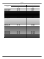
Model Head up / Hauteur d'élévation / Prevalencia Flow / Débit / Caudal
H [ft] Q [gpm]
DRENAG 1000 MA
max 40
max 104
DRENAG 1000 MNA
max 40
max 104
DRENAG 1000 TNA
max 51.2
max 111
DRENAG 1200 MA
max 58.4
max 113.5
DRENAG 1200 MNA
max 58.4
max 113.5
DRENAG 1200 TNA
max 55.4
max 127
FEKA VS 550 MA
max 22
max 79
FEKA VS 550 MNA
max 22
max 79
FEKA VS 550 MA
max 21
max 82
FEKA VS 550 MNA
max 21
max 82
FEKA VS 550 TNA
max 22
max 84.8
FEKA VX 550 MA
max 22
max 81.8
FEKA VX 550 MNA
max 22
max 81.8
FEKA VS 750 MA
max 30.2
max 111
FEKA VS 750 MNA
max 30.2
max 111
FEKA VS 750 TNA
max 29.5
max 97.5
FEKA VX 750 MA
max 32.8
max 98.3
FEKA VX 750 MNA
max 32.8
max 98.3
FEKA VX 1000 MA
max 36.4
max 117.6
FEKA VX 1000 MNA
max 36.4
max 117.6
FEKA VX 1200 MA
max 45.6
max 139
FEKA VX 1200 MNA
max 45.6
max 139
FEKA VS 1000 MA
max 35.8
max 113.2
FEKA VS 1000 MNA
max 35.8
max 113.2
FEKA VS 1000 TNA
max 35.3
max 101.5
FEKA VS 1200 MA
max 46.6
max 144.8
FEKA VS 1200 MNA
max 46.6
max 144.8
FEKA VS 1200 TNA
max 45
max 128


DAB PUMPS LTD.
6 Gilbert Court
Newcomen Way
Severalls Business Park
Colchester
Essex
C04 9WN - UK
Tel. +44 0333 777 5010
DAB PUMPS GmbH
Am Nordpark 3
41069 Mönchengladbach, Germany
Tel. +49 2161 47 388 0
Fax +49 2161 47 388 36
DAB PUMPS HUNGARY KFT.
H-8800
Nagykanizsa, Buda Ernő u.5
Hungary
Tel. +36 93501700
DAB PUMPS DE MÉXICO, S.A. DE C.V.
Av Amsterdam 101 Local 4
Col. Hipódromo Condesa,
Del. Cuauhtémoc CP 06170
Ciudad de México
Tel. +52 55 6719 0493
DAB PUMPS OCEANIA PTY LTD
426 South Gippsland Hwy,
Dandenong South VIC 3175 – Australia
Tel. +61 1300 373 677
DAB PUMPS B.V.DAB PUMPS B.V.
Albert Einsteinweg, 4Albert Einsteinweg, 4
5151 DL Drunen - Nederland5151 DL Drunen - Nederland
Tel. +31 416 387280Tel. +31 416 387280
Fax +31 416 387299Fax +31 416 387299
DAB PUMPS BVDAB PUMPS BV
‘tHofveld 6 C1‘tHofveld 6 C1
1702 Groot Bijgaarden - Belgium1702 Groot Bijgaarden - Belgium
Tel. +32 2 4668353Tel. +32 2 4668353
DAB PUMPS IBERICA S.L.DAB PUMPS IBERICA S.L.
Calle Verano 18-20-22Calle Verano 18-20-22
28850 - Torrejón de Ardoz - Madrid28850 - Torrejón de Ardoz - Madrid
SpainSpain
Tel. +34 91 6569545Tel. +34 91 6569545
Fax: + 34 91 6569676Fax: + 34 91 6569676
DAB PUMPS INC.
3226 Benchmark Drive
Ladson, SC 29456 - USA
Tel. 1- 843-797-5002
Fax 1-843-797-3366
DAB PUMPS (QINGDAO) CO. LTD.
No.10 Xindong Road, Jiulong Town, Jiaozhou
City, Qingdao City, Shandong Province - China
mailto:[email protected]
DAB PUMPS S.p.A.
Via M. Polo, 14 - 35035 Mestrino (PD) - Italy
Tel. +39 049 5125000 - Fax +39 049 5125950
www.dabpumps.com
DAB PUMPS SOUTH AFRICA
Twenty One industrial Estate,
16 Purlin Street, Unit B, Warehouse 4
Olifantsfontein - 1666 - South Africa
Tel. +27 12 361 3997
DAB PUMPS POLAND SP. z.o.o.
Ul. Janka Muzykanta 60
02-188 Warszawa - Poland
01/24 cod.60203970
-
 1
1
-
 2
2
-
 3
3
-
 4
4
-
 5
5
-
 6
6
-
 7
7
-
 8
8
-
 9
9
-
 10
10
-
 11
11
-
 12
12
-
 13
13
-
 14
14
-
 15
15
-
 16
16
-
 17
17
-
 18
18
-
 19
19
-
 20
20


DAB Drenag 1000, Drenag 1200 Manual de usuario
- Tipo
- Manual de usuario
- Este manual también es adecuado para
en otros idiomas
Artículos relacionados
-
DAB FEKA VS Instruction For Installation And Maintenance
-
-
-
-
-
-
