
TOOLS REQUIRED TABLE OF CONTENTS
(x2)
(x1) (x1) (x1)
(x2) (x1) (x1) BQL (x1)BQN (x1) (x1)
7/16" (≈11 mm) (x2)
1/2" (≈13 mm) (x2)
3/4" (≈19 mm)
5/16" (≈8 mm)
Icon Legend....................................................4
Warnings & Notices........................................5
Wall/Truss Support Installation....................6
Truss Support Assembly..............................15
Parts Identifi er..............................................27
Door Support Assembly...............................32
Cleaning & Care..........................................51
Registration................................................52
Warranty.....................................................53
Pour le français, voir la page 2. Para el español, ver la página 3.
ASSEMBLY INSTRUCTIONS
EXTREME
WEATHER KIT
MODEL 60011
BEFORE ASSEMBLY:
• Assemble on a level surface
• 3+ people recommended for setup
CONTACT LIFETIME® CUSTOMER SERVICE:
Call: 1-800-225-3865 Live Chat: www.lifetime.com/customerservice
(click on “LIVE CHAT” tab)
For Customer Service in mainland Europe:
E-mail: [email protected]
QUESTIONS?
MODEL# AND PRODUCT ID (you will need both when contacting us)
Model Number: 60011
Product ID:

2
Légende d’ícônes...........................................4
Notifi cations et avis......................................5
Installation des supports des
murs/fermes................................................6
Assemblage des supports des fermes.......15
Identifi cateur des pièces............................27
Assemblage des supports des portes.......32
Nettoyage et entretien.................................51
Enregistrement..........................................52
Garantie.....................................................54
OUTILS REQUIS SOMMAIRE
(x2)
(x1) (x1) (x1)
(x2) (x1) (x1) BQL (x1)BQN (x1) (x1)
7/16 po (≈11 mm) (x2)
1/2 po (≈13 mm) (x2)
3/4 po (≈19 mm)
5/16 po (≈8 mm)
AVANT L’ASSEMBLAGE :
• Assembler sur une surface de niveau
• Nous recommendons 3+ adultes pour l’assemblage
For English, see page 1. Para el español, ver la página 3.
INSTRUCTIONS D’ASSEMBLAGE
KIT POUR LES CONDITIONS
MÉTÉOLOROGUIQUES
EXTRÊMES
MODÈLE n° 60011
CONTACTER AUX SERVICES À LA CLIENTÈLE LIFETIME® :
Composer le 1-800-225-3865
Chat en direct: www.lifetime.com/customerservice
(cliquer sur la languette «LIVE CHAT »)
Pour les services à la clientèle du continent européen :
É-mail : [email protected]
QUESTIONS ?
N° DE MODÈLE ET RÉFÉRENCE DU PRODUIT
(il faut avoir les deux en entrant en contact avec nous)
N° de modèle : 60011
Référence du produit :

3
Leyenda de íconos.........................................4
Notifi caciones y avisos................................5
Instalación de los soportes de los muros.....6
Ensamblaje de soportes de armazones.....15
Identifi cador de piezas................................27
Ensamblaje de soportes de puertas.........32
Limpieza y cuidado....................................51
Registro.....................................................52
Garantía....................................................55
INSTRUMENTAL REQUERIDO ÍNDICE
(x2)
(x1) (x1) (x1)
(x2) (x1) (x1) BQL (x1)BQN (x1) (x1)
7/16 in (≈11 mm) (x2)
1/2 in (≈13 mm) (x2)
3/4 in (≈19 mm)
5/16 in (≈8 mm)
ANTES DEL ENSAMBLE:
• Ensamblar sobre una superfi cie nivelada
• Recomendamos 3+ adultos para el ensamblaje
For English, see page 1. Pour le français, voir la page 2.
INSTRUCCIONES DE ENSAMBLAJE
JUEGO PARA
TIEMPO INCLEMENTE
MODELO n° 60011
PONERSE EN CONTACTO CON LOS SERVICIOS DE CLIENTES LIFETIME®:
Marcar : 1-800-225-3865
Chat en vivo: www.lifetime.com/customerservice
(cliquear en la lengüeta «LIVE CHAT»)
Para el servicio a clientes en el continente europeo:
Correo electrónico: [email protected]
¿PREGUNTAS?
MODELO E ID DEL PRODUCTO
(se necesitan los dos al contactarnos)
Número de modelo: 60011
ID del producto:

4
• Indicates the parts/no parts required for a section.
• Indique les pièces à utiliser/qu’aucone pièce n’est requise pour une section.
• Indica las piezas que se usarán/que no necesitan en una sección.
• Indicates special heed should be taken when reading.
• Indique qu’une attention spéciale doit être portée à la lecture.
• Indica que uno debe prestar atención al leer.
• Indicates the hardware to be used for a section.
• Indique la quincaillerie à utiliser pour une section.
• Indica los artículos de ferretería que se usarán para una sección.
• Indicates the tools to be used for a section.
• Indique les outils à utiliser pour une section.
• Indica las herramientas que se utilizarán para una sección.
• Indicates the number of adults required to perform a specifi c step, e.g., 2, 3, 4, etc.
• Indique le nombre d’adultes requis pour e ectuer une étape spécifi que, p. ex., 2, 3, 4, etc.
• Indica el número de adultos requeridos para realizar un paso específi co, p.ej., 2, 3, 4, etc.
• Indicates no hardware required for a specifi c page or section.
• Indique qu’aucun matériel n’est requis pour une page précise.
• Indica que no se necesitan los artículos de ferretería para una página específi ca.
• Indicates to use/not use an electric drill for a specifi c step.
• Indique quand utiliser une/que ne pas utiliser de perceuse électrique pour une étape précise.
• Indica la utilización de/que no utilizar un taladro eléctrico para un paso específi co.
ICON LEGEND / LÉGENDE DES ICÔNES / SIGNIFICADO DE LOS ÍCONOS
• These nuts are centerlock nuts. They are designed to be tight; therefore, they will be harder to tighten. Tighten until fl ush with the metal or plastic.
• Ces écrous sont des écrous de blocage central. Ils sont conçus pour être serrés; de ce fait, ils seront plus di ciles à resserrer. Serrer jusqu’à ce qu’ils
soient au ras du métal ou du plastique.
• Estas tuercas son tuercas de bloqueo central. Están diseñadas para estar apretadas; por lo tanto, serán más difíciles de apretar. Apriételas hasta que
estén al ras del metal o plástico.

5
English:
• Failure to follow these warnings may result in serious injury or property damage and will void warranty.
• To ensure safety, do not attempt to assemble this product without following the instructions carefully.
• Be aware that plastic pieces can be damaged by overtightening the screws. To avoid damage, we strongly recommend
the use of a drill with a low torque setting. A #2 Phillips screwdriver may also be used.
• All who participate in the assembly process should wear safety glasses throughout the assembly.
• If using a ladder during assembly, use extreme caution.
• Proper and complete assembly are essential to reduce the risk of accident or injury.
• Most injuries are caused by misuse and/or not following instructions. Use caution when using this product.
Le français :
• Le non-respect de ces avertissements peut entraîner, en conséquence, des blessures sérieuses ou dommages à la propriété et annulera la
garantie.
• Pour assurer la sécurité, ne pas tenter d’assembler ce produit sans suivre attentivement les instructions.
• Il est possible d’endommager les pièces en plastique en serrant excessivement les vis. Pour éviter d’endommager le
plastique, nous recommandons vivement l’usage d’une perceuse électrique de faible puissance. Un tournevis cruciforme
n° 2 peut être utilisé.
• Toutes les personnes qui participent à l’assemblage doivent porter des lunettes de sécurité tout le long de l’assemblage.
• Si vous utilisez une échelle pendant le montage, l’utiliser avec prudence.
• L’assemblage correct et complète est essentiel pour réduire le risque des dangers ou des blessures.
• La plupart des blessures sont causées par l’abus et/ou par le non-respect des instructions. Faires attention en utilisant ce produit.
El español:
• El incumplimiento de seguir estas advertencias puede resultar en lesiones graves o daño a la propiedad y anulará la garantía.
• Para asegurar la seguridad, no intentar armar este producto sin seguir detenidamente las instrucciones.
• Es posible endañar las piezas de plástico por apretar los tornillos. Para evitar dañar el plástico, recomendamos el uso de
un taladro eléctrico de baja potencia. Se puede usar también un destornillador de punta Phillips no. 2.
• Todos los que participan en el ensamble del producto deben llevar gafas de seguridad a lo largo del ensamble.
• Si se utiliza una escalera durante el ensamble, tener cuidado extremo.
• El armado propio y completo son esenciales para reducir el riesgo de accidentes y lesiones.
• La mayoría de las lesiones son causadas por el uso erróneo y/o el incumplimiento de seguir las instrucciones. Tener cuidado al usar este
producto.
WARNINGS & NOTICES / AVERTISSEMENTS ET AVIS / ADVERTENCIAS Y AVISOS

6
BRK (x24)
ADZ (x73)
71 1/8”
BRF (x7)
BQY (x1)
BRG (x1)
71 1/8”
16 1/2”
BQZ (x8)
BQU (x2)
BRN (x11)
BRP (x16)
ADJ (x16)
WALL/TRUSS SUPPORT ASSEMBLY / ASSEMBLAGE DU SUPPORT DES MURS ET DES FERMES /
ENSAMBLAJE DEL SOPORTE DE LOS MUROS Y ARMAZONES
7/16 in/po (≈11 mm) (x2) 3/4 in/po (≈13 mm) BQL (x1)
BRQ
Metal Parts / Pièces en métal / Piezas de metal
Hardware Bag / Sac de quincaillerie / Bolsa de herraje
TOOLS REQUIRED / OUTILS REQUIS / INSTRUMENTAL REQUERIDO
PARTS REQUIRED / PIÈCES REQUISES / PIEZAS REQUERIDAS
HARDWARE REQUIRED / QUINCAILLERIE REQUISE / HERRAJE REQUERIDO
1
71 1/8 in/po (≈1,8 m)
16 1/2 in/po (≈42 cm)
71 1/8 in/po (≈1,8 m)

7
TOOLS AND HARDWARE REQUIRED / OUTILS ET QUINCAILLERIE REQUIS / INSTRUMENTAL Y HERRAJE REQUERIDOS
• Attach a lower bracket (BQZ) to the bottom of each long support channel (BRF) and support channel for window wall panel
(bqy) and secure with two (2) hex bolts (BRP) and two (2) cap nuts (ADJ). Do not overtighten the nuts.
• Attacher un Support inférieur (BQZ) à l’extrémité inférieure de chaque canal de support long (BRF) et canal de support pour
le panneau mural avec fenêtre (BQY) à l’aide de deux (2) boulons hexagonaux (BRP) et deux (2) écrous borgnes (ADJ). Ne pas
serrer excessivement les écrous.
• Sujetar un soporte inferior (BQZ) à l’extremo inferior de cada canal de soporte largo (BRF) y cada canal de soporte para el
panel mural con ventana (BQY) usando dos (2) pernos hexagonales (BRP) y dos (2) tuercas ciegas (ADJ). No apretar demasiado las
tuercas.
ADJ
BRP
BQZ
BRF
BRP (x16)
(You might not use all the Bolts)
(Puede que no use todos los pernos)
(Il se peut que vous n’utilisez pas tous les boulons)
ADJ (x16)
(You might not use all the Nuts)
(Puede que no use todas las tuercas)
(Il se peut que vous n’utilisez pas tous les écrous)
7/16 in/po (x2)
(≈11 mm (x2))
1.1
X SECTION 1 (CONTINUED) / SECTION 1 (SUITE) / SECCIÓN 1 (CONTINUACIÓN)

8
TOOLS AND HARDWARE REQUIRED / OUTILS ET QUINCAILLERIE REQUIS / INSTRUMENTAL Y HERRAJE REQUERIDOS
• Attach a long support channel (BRF) to the end of a truss gutter channel using two (2) self-tapping screws (BRK) as
shown. Connect the support channel to the wall panel using eight (8) screws (ADZ) through the holes along both sides
of the length of the support channel. Repeat this step for all support channels except for any over a window wall panel.
• Attacher un canal de support long (BRF) à l’extrémité d’un canal de gouttière à l’aide de deux (2) vis autotaraudeuses
(BRK) comme indiqué. Attacher le canal de support au panneau mural à l’aide de huit (8) vis (ADZ) à travers les trous
le long des deux côtés du canal de support. Répéter cette étape pour tous les canaux de support sauf pour les panneaux
muraux avec fenêtre.
• Sujetar un canal de soporte long (BRF) al extremo de un canalón de armazón usando dos (2) tornillos autoroscantes
(BRK) como se muestra. Sujetar el canal de soporte al panel mural usando ocho (8) tornillos (ADZ) por los agujeros a
lo largo de los dos lados del canal de soporte. Repetir este paso para todos los canales de soporte largos salvo los canales de
soporte cortos para el panel mural con ventana.
ADZ (x40)
(You might not use all the Screws)
(Puede que no use todos los tornillos)
(Il se peut que vous n’utilisez pas toutes les vis)
ADZ
BRK (x10)
(You might not use all the Screws)
(Puede que no use todos los tornillos)
(Il se peut que vous n’utilisez pas toutes les vis)
BRK
BRK
BRF
BRF
BQL
1.2
X SECTION 1 (CONTINUED) / SECTION 1 (SUITE) / SECCIÓN 1 (CONTINUACIÓN)

9
TOOLS AND HARDWARE REQUIRED / OUTILS ET QUINCAILLERIE REQUIS / INSTRUMENTAL Y HERRAJE REQUERIDOS
• Attach a long support channel (BQY) to the end of the truss gutter channel just above the window wall panel using two
(2) self-tapping screws (BRK). Connect the support channel to the window wall panel using ten (10) screws (adz). Repeat
this step for any other window wall panels. If you have no window wall panel, you can still use this part on a standard wall panel.
• Attacher un canal de support long (BQY) à l’extrémité d’un canal de gouttière juste au-dessous le panneau mural à
fenêtre à l’aide de deux (2) vis autotaraudeuses (BRK). Sujete le canal au panneau mural à fenêtre à l’aide de dix (10)
vis (ADZ). Répéter cette étape pour des autres panneaux muraux à fenêtre. S’il n’y a pas de panneau mural avec fenêtre, utiliser ce
canal pour les panneaux muraux normaux.
• Sujetar un canal de soporte largo (BQY) al canalón de armazón apenas encima el panel mural para la ventana usando
dos (2) tornillos autoroscantes (BRK). Sujetar el canal de soporte al panel mural para la ventana usando diez (10)
tornillos (ADZ). Repetir este paso para cualquier otro panel mural para la ventana. Si no hay un panel mural para la ventana, se puede
usar este canal en un panel mural normal.
ADZ (x10) BRK (x2)
ADZ
BQY
BRK
BRK
BQL
1.3
X SECTION 1 (CONTINUED) / SECTION 1 (SUITE) / SECCIÓN 1 (CONTINUACIÓN)

10
TOOLS AND HARDWARE REQUIRED / OUTILS ET QUINCAILLERIE REQUIS / INSTRUMENTAL Y HERRAJE REQUERIDOS
• Attach a short support channel for window wall panel (BRG) to the top of the long support channel using four (4) self-
tapping screws (BRK). Repeat this step for any other window wall panels.
• Attacher un canal de support court pour le panneau mural avec fenêtre (BRG) à l’extrémité supérieure du canal de support
long à l’aide de quatre (4) vis autotaraudeuses (BRK). Répéter cette étape pour des autres panneaux muraux avec fenêtre.
• Sujetara un canal de soporte corto para el panel mural para la ventana (BRG) al extremo superior del soporte largo usando
cuatro (4) tornillos autoroscantes (BRK). Repetir este paso para cualquier otro panel mural con ventana.
BRK
BRK BRK
BRK
BRK (x8)
BQL
1.4
BRG
X SECTION 1 (CONTINUED) / SECTION 1 (SUITE) / SECCIÓN 1 (CONTINUACIÓN)

11
TOOLS AND HARDWARE REQUIRED / OUTILS ET QUINCAILLERIE REQUIS / INSTRUMENTAL Y HERRAJE REQUERIDOS
• Attach an upper bracket (BQU) to the top of a support channel using two (2) self-tapping screws (BRK) as shown. Repeat
this step for the second upper bracket.
• Attacher un support supérieur (BQU) à l’extrémité supérieure du canal de soporte à l’aide de deux (2) vis
autotaraudeuses (BRK) comme indiqué. Répéter cette étape pour le deuxième support supérieur.
• Sujetar un soporte superior (BQU) al tope del canal de soporte usando dos (2) tornillos autoroscantes (BRK) como se
muestra. Repetir este paso para el segundo soporte superior.
BQU
BRF
BRK BRK
BRK (x4)
BQL
1.5
X SECTION 1 (CONTINUED) / SECTION 1 (SUITE) / SECCIÓN 1 (CONTINUACIÓN)

12
TOOLS AND HARDWARE REQUIRED / OUTILS ET QUINCAILLERIE REQUIS / INSTRUMENTAL Y HERRAJE REQUERIDOS
ADZ
• Attach a truss/wall support channel with upper bracket assembly next to the first groove on the front, right corner
wall panel and secure with ten (10) screws (ADZ). Repeat this step for the front, left corner wall panel.
• Attacher un assemblage de canal de support avec un support supérieur à côté de la première rainure du panneau
mural avant droit, et l’attacher au mur à l’aide de dix (10) vis (ADZ). Répéter cette étape pour le panneau mural avant gauche.
• Sujetar un conjunto de canal de soporte con un soporte superior al lado de la primera ranura en el panel mural
delantero derecho. Sujetarlo usando diez (10) tornillos (ADZ). Repetir este paso para el panel mural delantero izquierdo.
• First groove in corner wall panel
• Première rainure dans le panneau mural angulaire
• Primera ranura en el panel mural angular
ADZ (x20)
X SECTION 1 (CONTINUED) / SECTION 1 (SUITE) / SECCIÓN 1 (CONTINUACIÓN)
1.6

13
TOOLS AND HARDWARE REQUIRED / OUTILS ET QUINCAILLERIE REQUIS / INSTRUMENTAL Y HERRAJE REQUERIDOS
• Connect the wall-to-floor support brackets (BQS) to the rear wall using screws (ADZ).
• Attacher les supports de plancher (BQS) au mur arrière à l’aide des vis (ADZ).
• Sujetar los soportes de piso (BQS) al muro trasero usando tornillos (ADZ).
ADZ (x3)
ADZ ADZ ADZ
BQS BQS BQS
1.7
X SECTION 1 (CONTINUED) / SECTION 1 (SUITE) / SECCIÓN 1 (CONTINUACIÓN)

14
TOOLS AND HARDWARE REQUIRED / OUTILS ET QUINCAILLERIE REQUIS / INSTRUMENTAL Y HERRAJE REQUERIDOS
• If you have a wood foundation, attach the wall-to-floor support brackets to the floor using the lag bolts (BRN). Repeat this step
to connect the truss/wall support channel floor brackets to the floor using the lag bolts. If you have a concrete foundation, visit your
local hardware store to acquire the bolts that would accommodate the thickness of your concrete. Use a hammer drill to insert
concrete screws. The diameter of the bolts should not exceed 1/2" (13 mm).
• S’il y a une plate-forme en bois, attacher les supports de plancher au plancher à l’aide des tire-fonds (BRN). Répéter cette
étape pour attacher los supports à canal de ferme/mur au plancher à l’aide des tire-fonds. S’il y a une plate-forme en béton, visiter
la quincaillerie locale pour acquerir des boulons qui peuvent satisfaire l’épaisseur de votre béton. Utiliser une perceuse à
percussion pour insérer les vis à béton. Le diamètre des boulons ne doivent pas dépasser de 13 mm (1/2 po).
• Si tiene una plataforma de madera, sujetar los soportes de piso al piso usando los tirafondos (BRN). Repetir este paso para
sujetar los soportes para el canal de armazón/muro al piso usando los tirafondos. Si tiene una plataforma de concreto, visitar la
ferretería local pour adquirir los pernos que pueden acomodar el espesor de su concreto. Usar un martillo perforador para
insertar los tornillos para concreto. El diámetro de los pernos no deben exceder de 13 mm (1/2 in).
BRN (x11)
(You might not use all Lag Bolts)
(Il se peut qu vous ne utilisiez pas tous les tire-fonds)
(Es posible que no use todos los tirafondos)
BRN BRN BRN
3/4 in/po
(≈19 mm)
1.8
X SECTION 1 (CONTINUED) / SECTION 1 (SUITE) / SECCIÓN 1 (CONTINUACIÓN)

15
BRB (x1)
59 1/2 in/po (≈1,51 m)
BFJ (x1)
19 3/4 in/po (≈50,2 cm)
BRK (x63)
BRA (x1)
ADZ (x32)
BRL (x1)
BQI (x1)
AAN (x1)
BES (x6)
ADJ (x6)
AHS (x2)
ADV (x6)
BQW (x12)
BQX (x2)
BRC (x8)
BRD (x3)
26 5/8”
BRE (x4)
BQN (x1)
7/16 in/po (≈11 mm) (x2) 1/2 in/po (≈13 mm) (x2) BQL (x1)
BRR
Metal Parts / Pièces en métal / Piezas de metal
Hardware Bag / Sac de quincaillerie / Bolsa de herraje
TOOLS REQUIRED / OUTILS REQUIS / INSTRUMENTAL REQUERIDO
PARTS REQUIRED / PIÈCES REQUISES / PIEZAS REQUERIDAS
HARDWARE REQUIRED / QUINCAILLERIE REQUISE / HERRAJE REQUERIDO
TRUSS SUPPORT ASSEMBLY / ASSEMBLAGE DU SUPPORT DE FERMES / ENSAMBLAJE DEL SOPORTE
DE ARMAZONES
2
16 7/8 in/po (≈42,9 cm)
26 5/8 in/po (≈67,6 cm)

16
TOOLS AND HARDWARE REQUIRED / OUTILS ET QUINCAILLERIE REQUIS / INSTRUMENTAL Y HERRAJE REQUERIDOS
• Align roof brackets (BRC) with the first and third holes in the front roof panel as shown. Secure the roof brackets to the
right side of the roof and entry gable using three (3) screws (ADZ) per roof bracket. Repeat this step for the left end of the
entry gable as well as both ends of the rear gable.
• Aligner les supports de toit (BRC) avec le premier et troisième trous dans le panneau de toit avant comme indiqué.
Attacher les supports de toit à l’extrémité droite du toit et du pignon d’entrée à l’aide de trois (3) vis (ADZ) par support
de toit. Répéter cette étape pour l’extrémité gauche du pignon d’entrée aussi bien que les deux extrémités du pignon arrière.
• Alinear los soportes de tejado (BRC) con el primer y tercer agujeros en el panel de dejado delantero como se muestra.
Sujetar los soportes de tejado al lado derecho del tejado y la fachada de entrada usando tres (3) tornillos (ADZ) por
soporte de tejado. Repetir este paso para el extremo izquierdo de la fachada de entrada además de los dos extremos de la fachada
trasera.
ADZ
ADZ
ADZ
ADZ
BRC
Third Hole / Troisième trou / Tercer agujero
Second Hole / Deuxième trou / Segundo agujero
First Hole / Premier trou / Primer agujero
BRC
ADZ (x24)
BRC (x8)
2.1
X SECTION 2 (CONTINUED) / SECTION 2 (SUITE) / SECCIÓN 2 (CONTINUACIÓN)

17
TOOLS AND HARDWARE REQUIRED / OUTILS ET QUINCAILLERIE REQUIS / INSTRUMENTAL Y HERRAJE REQUERIDOS
• Abutt the truss gussett (BQW) against the truss gutter channel and make the top, horizontal border of the truss gusset
parallel with the truss brace. Attach a gusset to the truss gutter channel and truss brace using four (4) self-tapping
screws (BRK) as shown. Repeat this step for both sides and both ends of each truss.
• Mettre le gousset (BQW) contre le canal de gouttière, et faire que le bord horizontal supérieur du gousset soit
parallèle au support de ferme. Attacher un gousset au canal de gouttière et le support de ferme à l’aide de quatre
(4) vis autotaraudeuses (BRK) comme indiqué. Répéter cette étape pour les deux côtés et les deux extrémités de chaque ferme.
• Lindar la placa de refuerzo (BQW) con el canalón de armazón, y hacer que el borde horizontal superior de la placa de
refuerzo esté paralelo con el soporte de armazón. Sujetar la placa al canalón y al soporte usando cuatro (4) tornillos
autoroscantes (BRK) como se muestra. Repetir este paso para los dos lados y los dos extremos de cada armazón.
• Truss Gutter Channel
• Canal de gouttière
• Canalón de armazón
BQW
BRK
BRK
BRK
BRK
• Truss Brace
• Support de ferme
• Soporte de armazón
BRK (x48)
(You might not use all the Screws)
(Il se peut que vous n’utilisiez pas toutes les vis)
(Es posible que no use todos los tornillos)
2.2
Note: Ensure the border of the Truss Gusset is level and parallel with the Truss Brace.
Note : Faire que le bord horizontal supérieur du gousset soit parallèle au support de ferme.
Nota: Hacer que el borde horizontal superior de la placa de refuerzo esté paralelo con el soporte de armazón.
!
X SECTION 2 (CONTINUED) / SECTION 2 (SUITE) / SECCIÓN 2 (CONTINUACIÓN)

18
TOOLS AND HARDWARE REQUIRED / OUTILS ET QUINCAILLERIE REQUIS / INSTRUMENTAL Y HERRAJE REQUERIDOS
• Place a short truss brace (BRD) up into a truss assembly, and insert the threaded rod through the short truss
brace and truss assembly as shown. Loosely tighten the cap nut removed in the previous step.
• Mettre un support court de ferme (BRD) à l’intérieur de la ferme, et insérer la tige filetée à travers les trous dans le
support court et la ferme comme indiqué.
Serrer à la main les écrous borgnes retirés dans
l’étape précédente.
• Colocar el soporte corto de armazón (BRD) en
un armazón, e insertr la varilla roscada por
el agujero en el soporte corto y el armazón
como se muestra. Apretar a mano las tuerca
ciega que se retiró en el paso anterior.
• Remove the bottom cap nut from the threaded rod in one of the trusses.
• Retirer l’écrou borgne
inférieure de la tige filetée
d’une des fermes.
• Retirar la tuerca ciega
inferior de la varilla roscada
en uno de los armazones.
• Threaded Rod
• Tige filetée
• Varilla roscada
• Cap Nut
• Écrou borgne
• Tuerca ciega
BRD
7/16 in/po (x2)
11 mm (x2)
2.3
2.4
X SECTION 2 (CONTINUED) / SECTION 2 (SUITE) / SECCIÓN 2 (CONTINUACIÓN)

19
TOOLS AND HARDWARE REQUIRED / OUTILS ET QUINCAILLERIE REQUIS / INSTRUMENTAL Y HERRAJE REQUERIDOS
BRK
BRK
• Ensure the short truss brace is horizontal and up against the truss gutter channel as shown. Secure the short truss
brace to the truss assembly using four (4) self-tapping screws (BRK). Repeat steps 2.3–2.6 For each truss assembly.
• Veiller à ce que le support court de ferme est horizontal et contre le canal de gouttière comme indiqué. Ensuite,
attacher le support court à la ferme à l’aide de quatre (4) vis autotaraudeuses (BRK). Répéter les étapes 2.3 – 2.6 pour
chaque ferme.
• Asegurarse que el soporte corto de armazón es horizontal y contra el canalón de armazón como se muestra.
Entonces, sujetar el soporte corto al armazón usando cuatro (4) tornillos autoroscantes (BRK). Repetir los pasos 2.3–2.6
para cada ensamble de armazón.
BQL
2.5
BRK (x12)
(You might not use all the Screws)
(Il se peut que vous n’utilisiez pas toutes les vis)
(Es posible que no use todos los tornillos)
X SECTION 2 (CONTINUED) / SECTION 2 (SUITE) / SECCIÓN 2 (CONTINUACIÓN)

20
TOOLS AND HARDWARE REQUIRED / OUTILS ET QUINCAILLERIE REQUIS / INSTRUMENTAL Y HERRAJE REQUERIDOS
• Insert an end cap (AHS) into each end of the rear gable support (BFJ).
• Insérer un capuchon (AHS) dans cada extrémité du support à pignon arrière (BFJ).
• Insertar un tapón (AHS) dentro de cada extremo del soporte de la fachada trasera (BFJ).
• Secure the support to the rear gable using four (4) screws (ADV) at the locations indicated.
• Attacher le support au pignon arrière à l’aide de quatre (4) vis (ADV) aux endroits indiqués.
• Sujetar el soporte a la fachada trasera usando cuatro (4) tornillos (ADV) a las ubicaciones indicadas.
AHS
AHS
BFJ
ADV
ADV
BFJ
ADV ADV
AHS (x2) ADV (x4)
2.6
2.7
X SECTION 2 (CONTINUED) / SECTION 2 (SUITE) / SECCIÓN 2 (CONTINUACIÓN)

21
TOOLS AND HARDWARE REQUIRED / OUTILS ET QUINCAILLERIE REQUIS / INSTRUMENTAL Y HERRAJE REQUERIDOS
BQX
BRA
BQX
• Slide the center and two outer support brackets (BRA & BQX) down behind the holes in the gable support as shown.
• Faire glisser le support central et les deux latéraux (BRA et BQX) derrière des trous dans le support de pignon comme
indiqué.
• Deslizar el soporte central y los dos laterales (BRA y BQX) detrás de los agujeros en el soporte de fachada como se
muestra.
2.8
X SECTION 2 (CONTINUED) / SECTION 2 (SUITE) / SECCIÓN 2 (CONTINUACIÓN)

22
TOOLS AND HARDWARE REQUIRED / OUTILS ET QUINCAILLERIE REQUIS / INSTRUMENTAL Y HERRAJE REQUERIDOS
• Secure the two outer support brackets to the rear wall and gable using two (2) screws (ADV) and eight (8) screws (ADZ).
• Attacher les deux supports latéraux au mur
et pignon arrières à l’aide de deux (2) vis (ADV)
et huit (8) vis (ADZ).
• Sujetar los dos soportes laterales al muro
trasero y la fachada trasera usando dos (2)
tornillos (ADV) y ocho (8) tornillos (ADZ).
• Using the 5/16" (8 mm) drill bit (BQN), drill a hole through the center hole on the gable support, center support
bracket, and through the rear gable.
• À l’aide d’une mèche de 5/16 po (8 mm) (BQN),
percer un trou à travers le trou central du
support de pignon, le support central, et à
travers le pignon arrière de l’abri.
• Usando la Broca de 5/16 in (8 mm) (BQN), taladrar
un agujero por el agujero central del soporte de
la fachada trasera, el soporte central, y por la
fachada trasero de la caseta.
ADZ (x3)
ADV
ADV
ADZ (x3)
ADZ (x2)
ADV (x2)
ADZ (x8)
BQN
2.9
2.10
X SECTION 2 (CONTINUED) / SECTION 2 (SUITE) / SECCIÓN 2 (CONTINUACIÓN)

23
TOOLS AND HARDWARE REQUIRED / OUTILS ET QUINCAILLERIE REQUIS / INSTRUMENTAL Y HERRAJE REQUERIDOS
• In the truss brace closest to the rear wall, there is a square hole near one of the ends. Drill a 5/16" (8 mm) hole
approximately the same distance (about 5" (13 cm)) from the other end (the end without a hole) of the truss brace.
• Dans le support de ferme le plus proche du mur arrière, il y a un trou carré près une des extrémités. Percer
un trou de 5/16 po (8 mm) approximativement la même distance (à peu près 13 cm (5 po)) de l’autre extrémité
(l’extrémité sans trou) du support de ferme.
• En el soporte de armazón más
cerca el muro trasero, hay un agujero
cuadrado cerca uno de los extremos.
Taladrar un agujero de 5/16 in (8 mm)
approximadamente la misma distancia
(unos 13 cm (5 in)) del otro extremo
(el extremo sin agujero) del soporte de
armazón.
BQI
BRL
BRL (x1) BQI (x1)
AAN (x1)
• Insert a hex bolt (BQI) through the washer (BRL) and
the hole in the rear gable. Secure the bolt with a cap
nut (AAN). Do not overtighten the cap nut.
• Insérer un boulon hexagonal (BQI) à travers la rondelle
(BRL) et le trou dans le pignon arrière. Bien le
serrer à l’aide d’un écrou à chape (AAN). Ne pas serrer
excessivement l’écrou.
• Insertar un perno hexagonal (BQI) por la rondana (BRL) y
por el agujero en la fachada trasera. Sujetar el perno
con una tuerca ciega (AAN). No apriete demasiado la tuerca.
BQN
• The square hole is on on of these ends
• Le trou carré est sur un des extrémités
• El agujero cuadrado está en uno de los dos extremos
1/2 in/po (x2)
(≈13 mm (x2))
2.11
2.12
X SECTION 2 (CONTINUED) / SECTION 2 (SUITE) / SECCIÓN 2 (CONTINUACIÓN)

24
TOOLS AND HARDWARE REQUIRED / OUTILS ET QUINCAILLERIE REQUIS / INSTRUMENTAL Y HERRAJE REQUERIDOS
• Insert a hex bolt (BES) through the square hole and the hole you just drilled in the truss brace nearest to the rear
wall. Remove the lower cap nut from the threaded rod. Secure three (3) truss/gable supports (BRE) to the truss brace
using two (2) cap nuts (ADJ) and the cap nut removed earlier.
• Insérer un boulon hexagonal (BES) dans le trou carré et le trou récemment percé dans le support de ferme le plus
proche du mur arrière. Enlever l’écrou borgne inférieur de la tige filetée. Attacher trois (3) supports à ferme/pignon
(BRE) au support de ferme à l’aide de deux (2) écrous borgnes (ADJ) et l’écrou borgne récemment enlevé.
• Insertar un perno hexagonal (BES) por el agujero cuadrado y el agujero que recién taladró en el soporte de armazón
más cerca el muro trasero. Retirar la tuerca ciega inferior de la varilla roscada. Ahora, sujetar tres (3) soportes
para el armazón/la fachada (BRE) al soporte de armazón usando dos (2) tuercas ciegas (ADJ) y la tuerca ciega que retiró
anteriormente.
2.13
BES
BRE
BRE
BRE
BES
ADJ
ADJ
ADJ
• Cap Nut
• Tuerca ciega
• Écrou borgne
ADJ (x2) BES (x2)
7/16 in/po (x2)
(≈11 mm (x2))
X SECTION 2 (CONTINUED) / SECTION 2 (SUITE) / SECCIÓN 2 (CONTINUACIÓN)

25
TOOLS AND HARDWARE REQUIRED / OUTILS ET QUINCAILLERIE REQUIS / INSTRUMENTAL Y HERRAJE REQUERIDOS
• Insert a Hex Bolt (BES) through each hole in the center and outer Support Brackets to secure the Truss/Gable
Supports to the Support Brackets. Tighten with Cap Nuts (ADJ).
• Insérer un boulon hexagonal (BES) dans chaque trou dans les supports central et latéraux pour attacher le support à
ferme/pignon aux supports central et latéraux. Bien les serrer à l’aide des écrous borgnes (ADJ).
• Insertar un perno hexagonal (BES) por cada agujero en los soportes central y laterales para sujetar los soportes de
armazón/fachada a los soportes central y laterales. Apretarlos bien usando las tuercas ciegas (ADJ).
BES
BES
BES
ADJ
ADJ ADJ
ADJ (x3) BES (x3)
7/16 in/po (x2)
(≈11 mm (x2))
2.14
X SECTION 2 (CONTINUED) / SECTION 2 (SUITE) / SECCIÓN 2 (CONTINUACIÓN)

26
TOOLS AND HARDWARE REQUIRED / OUTILS ET QUINCAILLERIE REQUIS / INSTRUMENTAL Y HERRAJE REQUERIDOS
• Align the notch in the Entry Gable Support Bracket (BRB) with the square hole in the middle of the Entry Header as
shown.
• Aligner l’encoche dans le support du pignon d’entrée (BRB) avec le trou carré au centre du linteau comme indiqué.
• Alinear la muesca en el soporte de la fachada de entrada (BRB) con el agujero cuadrado en el centro del dintel como
se muestra.
Notch
Encoche
Muesca
Notch
Encoche
Muesca
Square Hole
Trou carré
Agujero cuadrado
• Use a drill to secure the entry gable support bracket to the entry header using three (3) self-tapping screws (BRK) as
shown.
• Utiliser une perceuse électrique pour attacher le support du pignon d’entrée au linteau à l’aide de trois (3) vis
autotaraudeuses (BRK) comme indiqué.
• Usar un taladro eléctrico para sujetar el soporte de la fachada de entrada al dintel usando tres (3) tornillos
autoroscantes (BRK) como se muestra.
BRK
BRK
BRK
BRK (x3)
BRB
BRB (x1)
BQL
2.15
2.16
X SECTION 2 (CONTINUED) / SECTION 2 (SUITE) / SECCIÓN 2 (CONTINUACIÓN)

27
PARTS IDENTIFIER / IDENTIFICATEUR DE PIÈCES / IDENTIFICADOR DE PIEZAS
Remove this section for quick reference / Enlever cette section pour référence rapide / Reitirar esta sección para referencia rápida
THIS PAGE INTENTIONALLY LEFT BLANK
PAGE LAISSÉE BLANCHE INTENTIONNELLEMENT
ESTA PÁGINA SE HA DEJADO EN BLANCO INTENCIONADAMENTE

28
CONTENTS OF LARGE BOX / CONTENU DE LA GRANDE BOÎTE / CONTENIDO DE LA CAJA GRANDE
PARTS IDENTIFIER / IDENTIFICATEUR DE PIÈCES / IDENTIFICADOR DE PIEZAS
71 1/8”
59 1/2 in/po (≈1,51 m)
BFJ (x1)
BRF (x7)
BQR (x5)
BRE (x4)
BQT (x3)
BQY (x1)
65”
28 1/2”
71 1/8”
26 5/8”
Remove this section for quick reference / Enlever cette section pour référence rapide / Reitirar esta sección para referencia rápida
65" (≈1,65 m)
28 1/2" (≈72,4 cm)
71 1/8" (≈1,81 m)
71 1/8" (≈1,81 m)
59 1/2" (≈1,51 m)
26 5/8" (≈67,6 cm)

29
PARTS IDENTIFIER / IDENTIFICATEUR DE PIÈCES / IDENTIFICADOR DE PIEZAS
SMALL PARTS BOX / BOÎTE DE PETITES PIÈCES / CAJA DE PIEZAS PEQUEÑAS
HARDWARE & TOOL BAGS / SACS DE QUINCAILLERIE ET D’OUTILS / BOLSAS DE HERRAJE Y DEL INSTRUMENTAL
BQW (x12) BRA (x1)
BQX (x2)
BQZ (x8)
BQS (x3) BQU (x2)
BRC (x8) BRB (x1)
BQK (x1)
BRD (x3) BRG (x1)
19 3/4 in/po (≈50,2 cm) 16 1/2”
BRT BRRBRQ BRS
Remove this section for quick reference / Enlever cette section pour référence rapide / Reitirar esta sección para referencia rápida
16 7/8" (42,9 cm)
16 1/2" (≈41,9 cm)

30
PARTS IDENTIFIER / IDENTIFICATEUR DE PIÈCES / IDENTIFICADOR DE PIEZAS
Remove this section for quick reference / Enlever cette section pour référence rapide / Reitirar esta sección para referencia rápida
THIS PAGE INTENTIONALLY LEFT BLANK
PAGE LAISSÉE BLANCHE INTENTIONNELLEMENT
ESTA PÁGINA SE HA DEJADO EN BLANCO INTENCIONADAMENTE

31
TOOLS AND HARDWARE REQUIRED / OUTILS ET QUINCAILLERIE REQUIS / INSTRUMENTAL Y HERRAJE REQUERIDOS
• Remove the cap nut from the threaded rod, and reuse the cap nut to connect the last truss/gable support (BRE) to
the threaded rod. Then, connect the other end of the support to the entry gable support bracket using a hex bolt
(BES) and a cap nut (ADJ).
• Enlever l’écrou borgne de la tige filetée, et le réutiliser pour connecter le dernier support de la ferme/pignon (BRE) à la
tige filetée. Attacher l’autre extrémité du support au support à pignon d’entrée à l’aide d’un boulon hexagonal (BES) et
un écrou borgne (ADJ).
• Retirar la tuerca ciega de la varilla roscada, y reutilizarla para conectar el último soporte del armazón/fachada (BRE) a
la varilla roscada. Sujetar el otro extremo del soporte al soporte de la fachada de entrada usando un perno hexagonal
(BES) y una tuerca ciega (ADJ).
• Cap Nut
• Écrou borgne
• Tuerca ciega
ADJ
BES
BRE
ADJ (x1)
BES (x1)
7/16 in/po (x2)
(≈11 mm (x2))
2.17
X SECTION 2 (CONTINUED) / SECTION 2 (SUITE) / SECCIÓN 2 (CONTINUACIÓN)

32
BQT (x3)
28 1/2”
BQR (x5)
65”
BQN (x1)
7/16 in/po (≈11 mm) (x2)
1/2 in/po (≈13 mm) (x2)
BQL (x1)
BRS
Metal Parts / Pièces en métal / Piezas de metal
Hardware Bag / Sac de quincaillerie / Bolsa de herraje
TOOLS REQUIRED / OUTILS REQUIS / INSTRUMENTAL REQUERIDO
PARTS REQUIRED / PIÈCES REQUISES / PIEZAS REQUERIDAS
HARDWARE REQUIRED / QUINCAILLERIE REQUISE / HERRAJE REQUERIDO
BRH (x2)
ADX (x2)
BQJ (x4)
BQO (x1)
BRM (x2)
BRO (x6)
BRI (x2)
BRK (x18) ADZ (x24)
AHL (x1)
AVU (x4)
BRJ (x12)
DOOR SUPPORT ASSEMBLY / ASSEMBLAGE DU SUPPORT DES PORTES / ENSAMBLAJE DEL SOPORTE
DE LAS PUERTAS
65 in/po (≈1,65 m)
28 1/2 in/po (≈72,4 m)
3

33
TOOLS AND HARDWARE REQUIRED / OUTILS ET QUINCAILLERIE REQUIS / INSTRUMENTAL Y HERRAJE REQUERIDOS
BRK (x6)
BRK (x6)
Carriage Bolts
Boulons a carosserie
Pernos de carrocería
Cap Nuts
Écrous borgnes
Tuercas ciegas
Left Door
Porte gauche
Puerta izquierda
7/16 in/po
(≈11 mm)
BQR
BQL
3.1 • Remove the two cap nuts from the carriage bolts and align
the two center holes in a vertical door support (BQR) with those
in the left door as shown. Secure the support to the door
using the carriage bolts and cap nuts. Finally, ensure the
support is parallel to the edge of the door and secure it using
six (6) self-tapping screws (BRK) at the locations shown.
• Enlever les écrous borgnes des boulons de carrosserie,
et aligner les deux trous centraux dans le support vertical de
la porte (BQR) avec ceux de la porte gauche comme indiqué.
Bien attacher le support à la porte à l’aide des boulons à
carrosserie et les écrous borgnes. Enfin, veiller à ce que le
support est parralel au bord du la porte, et l’attacher à l’aide
de six (6) vis autotaraudeuses (BRK) aux indroits indqués.
• Retirar las tuercas ciegas de los pernos de carrocería,
y alinear los dos agujeros centrales en el soporte vertical
para la puerta (BQR) con ellos en la puerta izquierda como
se muestra. Sujetar el soporte angular a la puerta usando
los pernos de carrocería y las tuercas ciegas. Por último,
asegurarse que el canal angular es paralelo con el borde de
la puerta, y sujetarlo usando seis (6) tornillos autoroscantes
(BRK) à las ubicaciones indicadas.
X SECTION 3 (CONTINUED) / SECTION 3 (SUITE) / SECCIÓN 3 (CONTINUACIÓN)

34
TOOLS AND HARDWARE REQUIRED / OUTILS ET QUINCAILLERIE REQUIS / INSTRUMENTAL Y HERRAJE REQUERIDOS
• Place a second vertical door support (BQR) in the groove
on the back of the left door so the top of the support is at
the same height as the support you just attached. Secure
the support to the door using six (6) screws (ADZ) at the
locations indicated. Do not overtighten.
• Mettre un deuxième support vertical de la porte (BQR) en la
ranura en la partie arrière de la porte gauche pour que le
partie supérieure du support soit à la même hauteur que
le support attaché dans l’étape précédente. Attacher le
support à la porte à l’aide de six (6) vis (ADZ) aux endroits
indiqués. Ne pas serrer excessivement les vis.
• Poner un segundo soporte vertical para la puerta (BQR)
en la ranura en la parte trasera de la puerta izquierda
para que el extremo superior del soporte esté a la misma
altura que el soporte que sujetó en el paso anterior.
Sujetar el soporte a la puerta usando seis (6) tornillos
(ADZ) a las ubicaciones indicadas. No apretar demasiado los
tornillos.
Use this groove
Utiliser cette rainure
Usar esta ranura
ADZ (x6)
ADZ (x6)
BQR
3.2
X SECTION 3 (CONTINUED) / SECTION 3 (SUITE) / SECCIÓN 3 (CONTINUACIÓN)

35
TOOLS AND HARDWARE REQUIRED / OUTILS ET QUINCAILLERIE REQUIS / INSTRUMENTAL Y HERRAJE REQUERIDOS
1 1/2”
• Place a third vertical door support (BQR) on the back of the left door so the top of the support is at the same height
as the first two vertical door supports. Align the holes in the support over the hinge tube. While one adult holds the
end of the vertical door support on the mark, have another adult use the distance indicator (BQK) to set the distance in
from the right edge of the door. Finally, make a mark on the door through the top hole in the vertical door support.
• Mettre un troisième support vertical de la porte (BQR) sur la surface arrière de la porte gauche pour que l’extrémité
supérieure du support soit à la même hauteur que les premiers deux supports. Aligner les trous dans le support
par-dessus le tube de charnière. Pendant qu’un adulte soutient l’extrémité du support sur la marque, employer
l’indicateur de distance (BQK) pour marquer la distance du bord droit de la porte. Enfin, marquer la porte à travers le
trou supérieur du support.
• Poner un tercer soporte vertical para la puerta (BQR) en la superficie trasera de la puerta izquierda para que el tope
del soporte esté a la misma altura que los primeros dos soportes. Alinear los agujeros en el soporte encima del
tubo de bisagra. Mientras que un adulto mantenga el extremo del soporte en la marca, usar el indicador de distancia
(BQK) para marcar la distancia del borde derecho de la puerta. Por último, poner una marca en la puerta por el
agujero superior del soporte.
BQK
(Not to scale)
(Pas à l’échelle)
(No está escala)
• Mark the left door through this hole.
• Marquer la porte gauche à travers ce trou.
• Marcar la puerta izquierda por este agujero.
1 1/2" (3,81 cm)
BQK
BQR
3.3
Note: The distance indicator helps to align the vertical door support over the hinge tube in the door.
Remarque : L’indicateur de distance aide à aligner le support vertical de la porte par-dessus le tube de charnière en la puerta.
Nota: El indicador de distancia ayuda a alinear el soporte vertical de la puerta encima del tubo de bisagra en la puerta.
!
X SECTION 3 (CONTINUED) / SECTION 3 (SUITE) / SECCIÓN 3 (CONTINUACIÓN)

36
TOOLS AND HARDWARE REQUIRED / OUTILS ET QUINCAILLERIE REQUIS / INSTRUMENTAL Y HERRAJE REQUERIDOS
• Using an 1/8" (3 mm) drill bit (ARA), drill a hole straight into the hinge tube at the mark you just made. Do not drill all
the way through the door. Insert a screw (BRK) through the hole in the support and into the hinge tube.
• En utilisant une mèche de 1/8 po (3 mm) (ARA), percer le tube de charnière à la marque que vous venez de faire. Ne
pas percer à travers la porte entière. Insérer une vis (BRK) dans le trou supérieur et dans le tube de charnière.
• Usando una broca de 1/8 in (3 mm) (ARA), taladrar por el tubo de bisagra a la marca que recién hizo. No taladrar por
completo la puerta. Insertar un tornillo (BRK) por el agujero superior del soporte y dentro del tubo de bisagra.
1/8 in/po
(≈3 mm)
ARA
BRK (x1)
BRK
BQL
3.4
X SECTION 3 (CONTINUED) / SECTION 3 (SUITE) / SECCIÓN 3 (CONTINUACIÓN)

37
TOOLS AND HARDWARE REQUIRED / OUTILS ET QUINCAILLERIE REQUIS / INSTRUMENTAL Y HERRAJE REQUERIDOS
• Continue using the distance indicator to align
the holes in the angled channel over the hinge
tube and drill holes into the hinge tube at the five
locations shown. Secure the angled channel to
the left door hinge tube using five (5) more screws
(BRK).
• Continuer à utiliser l’indicateur de distance
pour aligner les trous dans le support par-dessus
le tube de charnière et percer le tube aux cinq
endroits indiqués. Bien attacher le support au
tube à l’aide de cinq (5) autres vis (BRK).
• Seguir usando el indicador de distancia para
alinear los agujeros en el soporte encima del
tubo de bisagra, y taladrar el tubo a las cinco
ubicaciones indicadas. Sujetar el soporte a la
puerta usando cinco (5) tornillos (BRK) más.
BRK (x5)
BRK (x5)
BQL
3.5
BQK
(Not to scale)
(Non à l’échelle)
(No está escala)
X SECTION 3 (CONTINUED) / SECTION 3 (SUITE) / SECCIÓN 3 (CONTINUACIÓN)

38
TOOLS AND HARDWARE REQUIRED / OUTILS ET QUINCAILLERIE REQUIS / INSTRUMENTAL Y HERRAJE REQUERIDOS
• Slide the distance indicator (BQK) down over
the back of the top of the door. The bent ends
should rest on the top of the door end channel.
The edge of the indicator should should rest
against the plastic ridge of the door to center
the bottom hole over the channel. Make a mark
through the hole in the indicator and onto the
channel as shown.
• Faire glisser l’indicateur de distance (BQK) sur
le côté arrière de la partie supérieure du
canal pour le bord de la porte. Les extrémités
dépliées doivent rester sur la partie supérieure
du canal. Le bord de l’indicateur doit rester
contre le bord en plastique de la rainure dans
la porte pour centrer le trou inférieur sur le
canal. Marquer le canal à travers le trou dans
l’indicateur comme indiqué.
• Poner el indicador de distancia (BQK) en el tope
del costado trasero del canal para el borde de
la puerta. Los extremos plegados del indicador
deben quedarse en el tope del canal. El borde
del indicador debe quedarse contra el borde
de plástico de la ranura en la puerta para
centrar el agujero en el canal. Poner una marca
en el canal por el agujero en el indicador de
distancia como se muestra.
• Using a pair of needle nose pliers, bend the small ends of the distance indicator (BQK) to a 90° angle as shown.
• En utilisant des pinces à becs pointus, déplier les petites extrémités de l’indicateur de distance (BQK) à un angle de
90° comme indiqué.
• Usando unas tenazas, plegar los pequeños extremos del indicador de distancia (BQK) à un ángulo de 90° como se
muestra.
Bend these ends
Pliez cettes extrémités
Pliegue estos extremos
Top View / Vue supérieure / Vista superior
Side View / Vue latérale / Vista lateral Bend to a 90° angle
Déplier à un angle de 90°
Plegar a un ángulo de 90°
BQK
• Make a mark on the channel through this hole.
• Marquer le canal à travers ce trou.
• Poner una marca en el canal por este agujero.
Door End Channel / Canal pour la bord de la port / Canal para el borde de la puerta
Ridge / Bord / Borde
BQK
BQK
(Not to scale)
(Non à l’échelle)
(No está escala)
3.6
3.7
X SECTION 3 (CONTINUED) / SECTION 3 (SUITE) / SECCIÓN 3 (CONTINUACIÓN)

39
TOOLS AND HARDWARE REQUIRED / OUTILS ET QUINCAILLERIE REQUIS / INSTRUMENTAL Y HERRAJE REQUERIDOS
Back of Door
Côté arrière
Costado trasero
BRM
BQJ
AVU
AVU
BQJ
BRI
BRH
• Using a 5/16" (8 mm) drill bit (BQN), and, keeping the drill bit level, drill a hole all the way through the door end
channel. Connect the required hardware to the door as shown.
• En utilisant une mèche de 8 mm (5/16 po) (BQN), et, en conservant la mèche horizontale, percer complètement à
travers le canal. Attacher la quincaillerie indiquée.
• Usando una broca de 8 mm (5/16 in) (BQN), y, guardando la broca horizontal, taladrar completamente por el canal.
Sujetar el herraje indicado.
BQN
BRH (x1)
BQJ (x2)
AVU (x2)
BRM (x1)
(Not to scale)
(Non à l’échelle)
(No está a escala)
BRI (x1)
(Not to scale)
(Non à l’échelle)
(No está a escala)
3.8
X SECTION 3 (CONTINUED) / SECTION 3 (SUITE) / SECCIÓN 3 (CONTINUACIÓN)

40
TOOLS AND HARDWARE REQUIRED / OUTILS ET QUINCAILLERIE REQUIS / INSTRUMENTAL Y HERRAJE REQUERIDOS
AVU (x2)
• Slide the distance indicator (BQK) up over the back of the bottom of the door. The bent ends should rest on the
bottom of the door end channel. The edge of the indicator should should rest against the plastic ridge of the door to
center the top hole over the channel. Make a mark through the hole in the indicator and onto the channel.
• Faire glisser l’indicateur de distance (BQK) sur le côté arrière de la partie inférieure du canal pour le bord de la porte.
Les extrémités dépliées doivent rester
sur la partie inférieure du canal. Le bord
de l’indicateur doit rester contre le bord
en plastique de la rainure dans la porte
pour centrer le trou supérieur sur le
canal. Marquer le canal à travers le trou
dans l’indicateur.
• Poner el indicador de distancia (BQK)
en la parte inferior del costado trasero
del canal para el borde de la puerta.
Los extremos plegados del indicador
deben quedarse en el extremo inferior
del canal. El borde del indicador debe
quedarse contra el borde de plástico de
la ranura en la puerta para centrar el
agujero en el canal. Poner una marca en
el canal por el agujero en el indicador de
distancia.
BQN
BRM
BQJ
AVU
AVU
BQJ
BRI
BRH
BRH (x1)
BQJ (x2)
BRM (x1)
(Not to scale)
(Non à l’échelle)
(No está a escala)
BRI (x1)
(Not to scale)
(Non à l’échelle)
(No está a escala)
BQK
(Not to scale)
(Non à l’échelle)
(No está a escala)
3.9
X SECTION 3 (CONTINUED) / SECTION 3 (SUITE) / SECCIÓN 3 (CONTINUACIÓN)

41
TOOLS AND HARDWARE REQUIRED / OUTILS ET QUINCAILLERIE REQUIS / INSTRUMENTAL Y HERRAJE REQUERIDOS
2 3/8”
• Make a mark 2 3/8" (6,03 cm) down from the top corner of the back of the left side of the right door (see
illustration). Place a vertical door support (BQR) over the hinge tube on the back of the right door so the top of the
support is on the mark as shown. While one adult holds the end of the vertical door support on the mark, use
the distance indicator to set the distance in from the left edge of the right door. Finally, make a mark on the door
through the top hole in the vertical door support.
• Faire une marque de ≈6,03 cm (2 3/8 po) du coin du côté gauche de la porte droite (voir l’illustration). Mettre
un support vertical de la porte (BQR) par-dessus le tube de charnière sur le côté arrière de la porte droite pour que
la partie supérieure du support soit sur la marque comme indiqué. Pendant qu’un adulte soutient l’extrémité du
support sur la marque, employer l’indicateur de distance (BQK) pour marquer la distance du bord gauche de la porte.
Enfin, marquer la porte à travers le trou supérieur du support.
• Poner una marca ≈6,03 cm (2 3/8 in) de la esquina superior del costado trasero del lado izquierdo de la puerta
derecha (ver la ilustación). Poner un soporte vertical para la puerta (BQR) encima del tubo de bisagra en el costado
trasero de la puerta derecha para que el extremo superior del soporte esté en la marca. Mientras que un adulto
mantenga el soporte en la marca, usar el Indicador de distancia para marcar la distancia del borde izquierdo de la
puerta derecha. Por último, poner una marca en la puerta por el agujero superior del soporte.
BQR
BQK
BQK
(Not to scale)
(Non à l’échelle)
(No está a escala)
3.10
Note: The distance indicator helps to align the vertical door support over the hinge tube in the door.
Remarque : L’indicateur de distance aide à aligner le support vertical de la porte par-dessus le tube de charnière en la puerta.
Nota: El indicador de distancia ayuda a alinear el soporte vertical de la puerta encima del tubo de bisagra en la puerta.
!
X SECTION 3 (CONTINUED) / SECTION 3 (SUITE) / SECCIÓN 3 (CONTINUACIÓN)
2 3/8 in/po (≈6,03 cm)

42
TOOLS AND HARDWARE REQUIRED / OUTILS ET QUINCAILLERIE REQUIS / INSTRUMENTAL Y HERRAJE REQUERIDOS
BRK (x1)
BRK
3.11 • Using an 1/8" (3 mm) drill bit (ARA), drill a hole straight into the hinge tube at the mark you just made. Do not drill all
the way through the door. Insert a screw (BRK) through the hole in the support and into the hinge tube.
• En utilisant une mèche de 1/8 po (3 mm) (ARA), percer le tube de charnière à la marque récemment faite. Ne pas
percer à travers la porte entière. Insérer une vis (BRK) dans le trou supérieur et dans le tube de charnière.
• Usando una broca de 1/8 in (3 mm) (ARA),
taladrar por el tubo de bisagra a la marca
recién taladrada. No taladrar completamente
por la puerta. Insertar un tornillo (BRK) por el
agujero superior del soporte y dentro del
tubo de bisagra.
1/8 in/po
(≈3 mm)
ARA
BQL
X SECTION 3 (CONTINUED) / SECTION 3 (SUITE) / SECCIÓN 3 (CONTINUACIÓN)

43
TOOLS AND HARDWARE REQUIRED / OUTILS ET QUINCAILLERIE REQUIS / INSTRUMENTAL Y HERRAJE REQUERIDOS
1/8 in/po
(≈3 mm)
ARA
BRK (x5)
BRK (x5)
BQL
• Continue using the distance indicator as a guide to align the holes in the vertical door support over the hinge tube
and drill holes into the hinge tube at the five locations shown. Secure the vertical door support to the left door hinge
tube using five (5) more screws (BRK).
• Continuer à utiliser l’indicateur de distance comme un guide pour aligner les trous dans le support vertical de la
porte par-dessus le tube de charnière, et percer le tube aux cinq
endroits indiqués. Bien attacher le support au tube de charnière
à l’aide de cinq (5) autres vis (BRK).
• Seguir usando el Indicador de distancia como una guía para
alinear los agujeros en el soporte vertical de la puerta encima
del tubo de bisagra à las cinco ubicaciones indicadas. Sujetar el
soporte al tubo usando cinco (5) screws (BRK) más.
3.12
X SECTION 3 (CONTINUED) / SECTION 3 (SUITE) / SECCIÓN 3 (CONTINUACIÓN)

44
TOOLS AND HARDWARE REQUIRED / OUTILS ET QUINCAILLERIE REQUIS / INSTRUMENTAL Y HERRAJE REQUERIDOS
BQO (x1)
• Thumb Lever
• Levier poussoir
• Palanca de pulgar
BQO
• Remove the pan-head screw from the locking mechanism on the right door and replace it with the flat-head screw
(BQO). Ensure the head of the flat-head screw is flush with the thumb lever.
• Enlever la vis du mechanisme de verrouillage dans la porte droite, et la remplacer avec la vis à tête plate (BQO).
Veiller à ce que la tête de la vis est au ras du levier poussoir.
• Retirar el tornillo del mecanismo de cierre de la puerta derecha, y reemplazarlo con el tornillo de cabeza plana (BQO).
Asegurarse que la cabeza del tornillo está al ras con la palanca de pulgar.
3.13
X SECTION 3 (CONTINUED) / SECTION 3 (SUITE) / SECCIÓN 3 (CONTINUACIÓN)

45
TOOLS AND HARDWARE REQUIRED / OUTILS ET QUINCAILLERIE REQUIS / INSTRUMENTAL Y HERRAJE REQUERIDOS
4 3/8”
• Measure down from the top of the right door about 4 3/8" (11 cm). Insert a vertical door support (BQR) into the
groove indicated with the top of the vertical door support at the mark as shown.
• Mesurer de la partie supérieure de la porte droite à peu près 11 cm (4 3/8 po). Insérer un support vertical de la
porte (BQR) dans la rainure indiquée avec la partie supérieure du support à la marque comme indiqué.
• Medir del borde superior de la puerta derecha unos 11 cm (4 3/8 in). Insertar un soporte vertical de la puerta (BQR)
en la ranura indicada con el tope del soporte a la marca como se muestra.
4 3/8 in/po
(11,1 cm)
BQR
• Use this groove
• Utiliser cette rainure
• Usar esta ranura
3.14
X SECTION 3 (CONTINUED) / SECTION 3 (SUITE) / SECCIÓN 3 (CONTINUACIÓN)

46
TOOLS AND HARDWARE REQUIRED / OUTILS ET QUINCAILLERIE REQUIS / INSTRUMENTAL Y HERRAJE REQUERIDOS
ADZ (x6)
ADZ (x6)
• Secure the vertical door support to the right door using six (6) screws (ADZ).
• Bien attacher le support vertical à la porte droite à l’aide de six (6) vis (ADZ).
• Sujetar el soporte vertical a la puerta derecha usando seis (6) tornillos (ADZ).
3.15
X SECTION 3 (CONTINUED) / SECTION 3 (SUITE) / SECCIÓN 3 (CONTINUACIÓN)

47
TOOLS AND HARDWARE REQUIRED / OUTILS ET QUINCAILLERIE REQUIS / INSTRUMENTAL Y HERRAJE REQUERIDOS
• Secure a door brace (BQT) to the door, vertical supports, and door end channel using four (4) self-tapping screws
(BRJ), two (2) self-tapping screws (BRO) and four (4) screws (ADZ) as shown. Do not overtighten screws.
• Attacher un support horizontal (BQT) à la porte, supports verticaux, et canal pour le bord de la porte à l’aide de
quatre (4) vis autotaraudeuses (BRJ), deux (2) vis autotaraudeuses (BRO) et quatre (4) vis (ADZ) comme indiqué. Ne pas
serrer excessivement les vis.
• Sujetar un soporte horizontal (BQT) a la puerta, a los soportes verticales, y al canal para le borde de la puerta usando
cuatro (4) tornillos autoroscantes (BRJ), dos (2) tornillos autoroscantes (BRO) y cuatro (4) tornillos (ADZ) como se muestra.
No apretar demasiado los tornillos.
• Important: If you have a door with a window in it,
do not insert these four (4) inner screws (ADZ).
• Important: S’il y a une fenêtre dans la porte, ne pas
insérer ces quatre (4) vis (ADZ) intérieures.
• Importante: Si hay una ventana en la puerta, no
insertar estos cuatro (4) tornillos (ADZ) interiores.
ADZ (x4)
BRJ
BRJ
BRO
ADZ BQT
ADZ
BRO (x2) BRJ (x4)
BQL
3.16
X SECTION 3 (CONTINUED) / SECTION 3 (SUITE) / SECCIÓN 3 (CONTINUACIÓN)
!
ADZ (x4)

48
TOOLS AND HARDWARE REQUIRED / OUTILS ET QUINCAILLERIE REQUIS / INSTRUMENTAL Y HERRAJE REQUERIDOS
• Secure two more door braces (BQT) to the door as the locations shown following the instructions in the previous
step.
• Attacher deux autres supports horizontaux (BQT) à la porte aux
endroits indiqués selon les instructions de l’étape précédente.
• Sujetar dos más soportes horizontales (BQT) a la puerta a
las ubicaciones indicadas según las instrucciones del paso
anterior.
ADZ (x8) BRO (x4)
BQT
BQT
BRJ (x8)
BQL
3.17
X SECTION 3 (CONTINUED) / SECTION 3 (SUITE) / SECCIÓN 3 (CONTINUACIÓN)

49
TOOLS AND HARDWARE REQUIRED / OUTILS ET QUINCAILLERIE REQUIS / INSTRUMENTAL Y HERRAJE REQUERIDOS
• Position the square hole in the strike plate (AHL) over the square hole in the floor panel as shown, and set the strike
plate over the hole. Secure the strike plate to the floor panel using two (2) screws (ADX). Do not overtighten screws.
• Positionner le trou carré dans la gâche (AHL) par-dessus le trou carré dans le panneau de plancher comme
indiqué, y mettre la gâche sur le trou. Attacher la gâche au panneau de plancher à l’aide de deux (2) vis (ADX). Ne
pas serrer excessivement les vis.
• Posicionar el agujero cuadrado en la placa de refuerzo (AHL) encima del agujero cuadrado en el panel de piso como
se muestra. Colocar la placa de refuerzo sobre el agujero, y sujetar la placa de refuerzo al panel de piso usando
dos (2) tornillos (ADX). No apretar demasiado los tornillos.
ADX (x2) AHL (x1)
ADX
• Square hole in Floor Panel
• Agujero cuadrado en el panel de piso
• Trou carré dans le panneau de plancher
AHL
3.18
X SECTION 3 (CONTINUED) / SECTION 3 (SUITE) / SECCIÓN 3 (CONTINUACIÓN)

50
TOOLS AND HARDWARE REQUIRED / OUTILS ET QUINCAILLERIE REQUIS / INSTRUMENTAL Y HERRAJE REQUERIDOS
• To secure the doors, simply turn the t-knob to insert the locking lever into the notch in the vertical door support.
Repeat this step for both locking levers.
• Pour fermer les portes, tourner le bouton en « T » pour insérer le levier de verrouillage dans l’encoche dans le
support vertical de la porte. Répéter cette étape pour l’autre levier de verrouillage.
• Para cerrar las puertas, girar el pomo en «T» para insertar la palanca de cierre en la muesca en el soporte
vertical de la puerta. Repetir este paso para la otra palanca de cierre.
3.19
X SECTION 3 (CONTINUED) / SECTION 3 (SUITE) / SECCIÓN 3 (CONTINUACIÓN)

51
Congratulations on your Lifetime® product purchase. By following the instructions below, your new Lifetime product should provide you with years of service and enjoyment.
The polyethylene panels are stain and solvent resistant. Most stains can be removed using a mild soap and a soft-bristled
brush. Abrasive cleaning materials may scratch the plastic and are not recommended. Repair scratches or rust spots on the
metal by sanding the a ected area lightly; using a rust preventative spray primer; and fi nally, spraying with a high-gloss spray
enamel paint. Avoid placing a direct heat source on or near surfaces unless using a heat barrier.
Nous vous félicitons d’avoir acheté ce produit Lifetime®. En suivant les instructions ci-dessous, votre nouveau produit Lifetime devrait vous fournir des années de service et de plaisir.
Les murs et les étagères en polyéthylène sont résistants aux taches et solvants de nettoyage. Pour les nettoyer, se servir
d’un savon doux et d’une brosse douce. Les produits abrasifs de nettoyage risquent d’égratigner le plastique et ne sont pas
recommandés. Pour réparer les égratignures ou taches de rouille sur le métal, frotter légèrement l’endroit a ecté au papier de
verre, puis passer une couche de produit vaporisant préventif, et, enfi n, vaporiser une peinture émail ultrabrillante. Éviter de
placer une source de chaleur directe sur ou près des surfaces, ou les protéger à l’aide d’une protection contre la chaleur.
CLEANING & CARE
NETTOYAGE ET ENTRETIEN
Felicidades por la compra de su producto Lifetime®. Al seguir las siguientes instrucciones, su nuevo producto Lifetime le brindará años de servicio y satisfacción.
Los paneles de polietileno son resistentes a las manchas y solventes. La mayoría de las manchas puede removerse usando un
jabón suave y un cepillo de cerdas suaves. Los materiales abrasivos para limpieza pueden rayar el plástico y no se recomien-
dan. Reparar rayones o manchas de óxido en el metal, lijando suavemente la parte afectada; usando un aerosol preventivo de
óxido y fi nalmente, rociando con una pintura de esmalte brillante. Evitar poner una fuente de calor directa en o cerca de las
superfi cies sin usar una barrera de calor.
LIMPIEZA Y CUIDADO

52
LIFETIME’S PROMISE TO YOU:
We invite you to read our privacy policy at www.lifetime.com
REGISTER today!
At Lifetime®, we are committed to providing innovative and quality products. While registering, you will have the opportunity to give us your feedback. Your input is valuable to us.
• You can also opt in to receive new product notifi cations or promotions.
• In the unlikely event of a product recall or safety modifi cation, your registration provides the information we need to notify you directly.
• Registration is fast, easy, and completely voluntary.
Maintaining your privacy is our long-standing policy at Lifetime®. And you can rest assured that Lifetime® will not sell or provide your personal data to other third parties, or
allow them to use your personal data for their own purposes.
REGISTER YOUR PRODUCT ONLINE AT WWW.LIFETIME.COM
LA PROMESA DE LIFETIME® PARA USTED:
Lo invitamos a leer nuestra política de privacidad en www.lifetime.com (sólo en inglés)
¡REGISTRARSE hoy mismo!
En Lifetime®, estamos comprometidos a ofrecer productos innovadores y de calidad. Al registrarse, usted tendrá la oportunidad de darnos su retroalimentación. Su información es valiosa para nosotros.
• También puede optar por recibir nuestras notifi caciones o promociones.
• En el caso improbable de que el producto deba ser retirado del mercado o que sufra alguna modifi cación, su registro provee la
información que necesitamos para notifi carle directamente.
• El registro es rápido, fácil y completamente voluntario.
Mantener privacidad es nuestra política permanente en Lifetime®. Y puede estar seguro que Lifetime® no venderá ni dará datos personales a terceros, ni les permitirá usar
datos personales para sus propios fi nes.
REGISTRAR EL PRODUCTO EN LÍNEA EN WWW.LIFETIME.COM
LA PROMESSE DE LIFETIME :
Nous vous invitons à lire notre politique de confi dentialité à www.lifetime.com (en anglais seulement)
ENREGISTRER CE PRODUIT aujourd’hui!
Chez Lifetime®, nous nous engageons à fournir des produits innovateurs de qualité. Lors de votre inscription, vous aurez l’occasion de nous faire parvenir vos commentaires. Votre opinion est importante
pour nous.
• On peut également choisir de recevoir des avis ou des promotions dans le cadre de nouveaux produits.
• Dans l’éventualité improbable d’un rappel ou d’un avis de sécurité, l’inscription fournit les renseignements nécessaires nous
permettant de communiquer avec vous.
• L’inscription est rapide, facile et complètement volontaire.
Conserver votre confi dentialité est notre politique de longue date chez Lifetime®. Vous pouvez donc être rassuré par le fait que Lifetime® ne vendra pas ou ne fournira pas vos
données personnelles à des tiers, et ne leur permettra pas d’utiliser vos données personnelles à leurs propres fi ns.
ENREGISTRER CE PRODUIT EN LIGNE À WWW.LIFETIME.COM

53
THE MANUFACTURER RESERVES THE RIGHT TO MAKE SUBSTITUTIONS TO WARRANTY CLAIMS IF PARTS ARE UNAVAILABLE OR OBSOLETE.
10-YEAR LIMITED FACTORY WARRANTY
Lifetime Lawn and Garden products are warranted to the original purchaser to be free from defects in material or
WORKMANSHIPFORAPERIODOFYEARSFROMTHEDATEOFORIGINALRETAILPURCHASE4HEWORDhDEFECTSvISDElNEDAS
imperfections that impair the use of the product. Defects resulting from misuse, abuse or negligence will void this
warranty. This warranty does not cover defects due to improper installation, alteration or accident. Lifetime recommends
THATNOMODIlCATIONSBEMADETOTHISPRODUCT4HISWARRANTYDOESNOTCOVERDAMAGECAUSEDBYVANDALISMRUSTING
“acts of nature”, natural disasters, normal wear and tear, or any other event beyond the control of the manufacturer.
This warranty is nontransferable and is expressly limited to the repair or replacement of defective products. If the
product is defective within the terms of this warranty, Lifetime Products, Inc. will repair or replace defective parts at
no cost to the purchaser. Shipping charges to and from the factory or distribution center are not covered and are
the responsibility of the purchaser. Labor charges and related expenses for removal, installation or replacement of
the product or its components are not covered under this warranty.
4HISWARRANTYDOESNOTCOVERSCRATCHINGSCUFlNGOROTHERCOSMETICDAMAGEOFTHEPRODUCTTHATMAYRESULTFROM
normal usage. In addition, defects resulting from intentional damage, negligence, or unreasonable use will void this
warranty / are not covered by this warranty.
Liability for incidental or consequential damages is excluded to the extent permitted by law. All merchandise is sold
on this condition, and no representative of the company may waive or change this policy. This product is not intended
for institutional or commercial use; Lifetime Products, Inc. does not assume any liability for such use. Institutional
or commercial use will void the warranty.
This warranty is expressly in lieu of all other warranties, expressed or implied, including warranties of merchantability
ORlTNESSFORUSETOEXTENTPERMITTEDBY&EDERALANDSTATELAW.EITHER,IFETIME0RODUCTS)NCNORANYREPRESENTATIVE
ASSUMESANYOTHERLIABILITYINCONNECTIONWITHTHISPRODUCT4HISWARRANTYGIVESYOUSPECIlCLEGALRIGHTSANDYOUMAY
also have other rights which vary from state to state.
Our goods come with guarantees that cannot be excluded under the Australian Consumer Law. You are entitled to a
replacement or refund for a major failure and for compensation for any other reasonably foreseeable loss or damage.
You are also entitled to have the goods repaired or replaced if the goods fail to be of acceptable quality and the failure
does not amount to a major failure.
ALL WARRANTY CLAIMS MUST BE ACCOMPANIED BY A SALES RECEIPT.
REPORT PRODUCT DEFECTS IN WRITING TO:
,)&%4)-%02/$5#43).#
PO Box 160010
&REEPORT#ENTER"LDG$
#LEARlELD54
&ORONLINEWARRANTYCLAIMSPLEASEVISITwww.lifetime.com/warranty
7ARRANTY$EPARTMENT
FOR INTERNATIONAL WARRANTY:
!LLWARRANTYCLAIMSMUSTBEACCOMPANIEDBYASALESRECEIPT2EPORTPRODUCTDEFECTSINWRITINGTOYOURREGIONALSALES
support representative. Please include your dated sales receipt and photographs of damaged parts.
4O)DENTIFYTHEREPRESENTATIVEFORYOURREGIONPLEASEVISITwww.lifetime.com/international

54
LIFETIME® PRODUCTS, INC. RÉSERVE LE DROIT DE FAIRE DES SUBSTITUTIONS EN CAS DE RECOURS EN GARANTIE SI LES PIÈCES NE SONT PAS DISPONIBLES OU SONT
OBSOLÈTES.
GARANTIE DE FABRICATION LIMITÉE DE 10 ANS
,ACHETEURDORIGINEDESPRODUITSPOURPELOUSESETJARDINSDE,IFETIMEB¼N¼lCIEDUNEGARANTIECONTRETOUTED¼FECTUOSIT¼
de matériel et de fabrication pour une période de 10 ans à compter de la date d’achat. On entend par « défaut »
une imperfection qui nuit à l’utilisation du produit. Tout défaut découlant d’une mauvaise utilisation, d’un abus ou
d’une négligence a pour effet d’annuler cette garantie. Cette garantie ne couvre pas les défauts attribuables à une
INSTALLATIONINAD¼QUATEUNEALT¼RATIONOUUNACCIDENT,IFETIMERECOMMANDEDENEPASAPPORTERDEMODIlCATIONS
à ce produit. Cette garantie ne couvre pas les dommages causés par le vandalisme, la corrosion par la rouille, les
cas de « force majeure », les catastrophes naturelles, la détérioration et l’usure normales et tout autre événement
indépendant de la volonté du fabricant.
Cette garantie n’est pas transférable et se limite expressément à la réparation ou au remplacement d’un produit
défectueux. Si le produit est défectueux au sens de cette garantie, Lifetime Products, Inc. réparera ou remplacera
les pièces défectueuses sans frais pour l’acheteur. Les frais d’expédition en partance ou en provenance de l’usine
OUDUCENTREDEDISTRIBUTIONNESONTPASCOUVERTSETINCOMBENT¸LACHETEUR,ESCOËTSRELATIFS¸LAMAINDUVRE
et les autres frais liés au retrait, à l’installation ou au remplacement du produit ou de ses composants ne sont pas
couverts par cette garantie.
Cette garantie ne couvre pas les rayures, les égratignures ou autres dommages esthétiques du produit découlant d’un
usage normal. De plus, tout défaut découlant d’un dommage volontaire, de négligence ou d’un usage déraisonnable
annule cette garantie et n’est pas couvert par cette garantie.
Dans la mesure permise par la loi, la société n’est pas responsable des dommages indirects ou accessoires. Toute
marchandise est vendue à cette condition et aucun représentant de la société ne peut renoncer à l’application de cette
POLITIQUEOULAMODIlER#EPRODUITNESTPASDESTIN¼¸DESlNSINSTITUTIONNELLESOUCOMMERCIALES,IFETIME0RODUCTS
Inc. n’assume aucune responsabilité à cet égard. Toute utilisation institutionnelle ou commerciale annule la garantie.
La présente garantie remplace expressément toute autre garantie, expresse ou implicite, y compris les garanties de
qualité marchande ou d’adaptation à un usage particulier dans la mesure permise par les lois du pays ou de l’État.
.I,IFETIME0RODUCTS)NCNIAUCUNDESESREPR¼SENTANTSNASSUMENTUNEQUELCONQUERESPONSABILIT¼ENLIENAVEC
ce produit. Cette garantie vous donne des droits juridiques précis et vous pourriez également avoir d’autres droits
selon l’État ou la province.
La garantie qui accompagne nos produits ne peut être exclue en vertu de la loi sur la protection du consommateur
de l’Australie. Le client a droit à un remplacement ou à un remboursement en cas de bris majeur et pour toute
autre perte ou dommage raisonnablement prévisible. Le client a aussi droit à ce que les produits soient réparés ou
REMPLAC¼SSIUNBRISSURVIENTETRENDLAQUALIT¼INACCEPTABLESANSPOURAUTANT½TREQUALIlABLEDEBRISMAJEUR
TOUTE RÉCLAMATION EN VERTU DE LA GARANTIE DOIT ÊTRE ACCOMPAGNÉE D’UN REÇU DE VENTE.
SIGNALEMENT ÉCRIT DE TOUT PRODUIT DÉFECTUEUX:
,)&%4)-%02/$5#43).#
PO Box 160010
&REEPORT#ENTER"LDG$
#LEARlELD54
0OUREFFECTUERENLIGNEUNER¼CLAMATIONSOUSGARANTIECONSULTEZCETTEADRESSEwww.lifetime.com/warranty
3ERVICEDELAGARANTIE
GARANTIE INTERNATIONALE:
Toute réclamation en vertu de la garantie doit être accompagnée d’un reçu de vente. Veuillez signaler par écrit tout produit
défectueux au représentant du soutien aux ventes de votre région Veuillez inclure le reçu de vente daté ainsi que des
photographies des pièces endommagées.
0OURCONNAÁTRELEREPR¼SENTANTDEVOTRER¼GIONVEUILLEZCONSULTERLEwww.lifetime.com/international

55
EL FABRICANTE SE RESERVA EL DERECHO DE HACER SUSTITUCIONES EN LOS ELEMENTOS REEMPLAZADOS BAJO GARANTÍA SI LAS PIEZAS
NO ESTÁN DISPONIBLES O SON OBSOLETAS.
GARANTÍA DE FÁBRICA LIMITADA POR 10 AÑOS
El comprador original recibe una garantía de que los productos de césped y jardín de Lifetime están libres de defectos
de material o mano de obra durante un período de 10 años a partir de la fecha de compra original al por menor.
La palabra “defectos” se defi ne como imperfección que imposibilita el uso del producto. Los defectos ocasionados
por el mal uso, el abuso o la negligencia anularán esta garantía. Esta garantía no cubre los defectos debidos a una
instalación incorrecta, una alteración o un accidente. Lifetime recomienda que no se realicen modifi caciones en este
producto. Esta garantía no cubre los daños causados por vandalismo, oxidación, “actos de la naturaleza”, desastres
naturales, desgaste normal o cualquier otro evento fuera del control del fabricante.
Esta garantía no es transferible y se limita expresamente a la reparación o reemplazo de productos defectuosos. Si el
producto resulta defectuoso dentro de los términos de esta garantía, Lifetime Products, Inc. reparará o reemplazará
las piezas defectuosas sin costo alguno para el comprador. Los gastos de envío hacia y desde la fábrica o el centro
de distribución no están cubiertos y son la responsabilidad del comprador. La mano de obra y los gastos relacionados
por la remoción, la instalación o la sustitución del producto o sus componentes no están cubiertos por esta garantía.
Esta garantía no cubre los rayones, los raspones ni otros daños superfi ciales del producto que pueden resultar del
uso normal. Asimismo, los defectos resultantes de daños intencionales, negligencia o uso indebido anularán o no
están cubiertos por esta garantía.
Se excluye la responsabilidad por daños imprevistos o derivados en la medida en que lo permita la ley. Toda la
mercancía se vende bajo estas condiciones y ningún representante de la empresa puede renunciar a ni cambiar
esta política. Este producto no está destinado para uso institucional o comercial; Lifetime Products, Inc. no asume
ninguna responsabilidad por dicho uso. El uso institucional o comercial anulará la garantía.
Esta garantía sustituye expresamente cualquier otra garantía, expresa o implícita, incluidas las garantías de
comercialización o idoneidad para su uso en la medida permitida por la ley federal y estatal. Ni Lifetime Products,
Inc., ni ningún representante asume ninguna otra responsabilidad en relación con este producto. Esta garantía le
otorga derechos legales específi cos y usted también puede tener otros derechos que varían de un estado a otro.
Nuestros productos vienen con garantías que no se pueden excluir bajo la Ley Australiana del Consumidor. Usted
tiene derecho a recibir un reemplazo o reembolso por un fallo grave y compensación por cualquier otra pérdida o
daño razonablemente previsible. También tiene derecho a la reparación o el reemplazo de los bienes si los bienes
no son de calidad aceptable y el fallo no supone un fallo grave.
TODOS LOS RECLAMOS DE GARANTÍA DEBEN ESTAR ACOMPAÑADOS POR UN RECIBO DE COMPRA.
REPORTE LOS DEFECTOS DEL PRODUCTO POR ESCRITO A:
LIFETIME PRODUCTS, INC.,
PO Box 160010
Freeport Center, Bldg. D-12
Clearfi eld, UT 84016-0010
Para realizar reclamos de garantía por internet, visite: www.lifetime.com/warranty.
Departamento de Garantías: (800) 225-3865
PARA LA GARANTÍA INTERNACIONAL:
Todos los reclamos de garantía deben estar acompañados por un recibo de compra. Reporte los defectos del producto por
escrito a su representante regional de apoyo de ventas. Por favor, incluya su recibo de compra con la fecha y fotografías de
las piezas dañadas.
Para identifi car al representante de su región, por favor visite: www.lifetime.com/international
GARANTIA NO VÁLIDA EN MÉXICO

56
www.lifetime.com
Or call: 1-800-424-3865
To purchase accessories or other Lifetime® products, visit us at:
www.lifetime.com
O marcar al 1-800-424-3865
Para comprar accesorios u otros productos de Lifetime®, visitarnos en:
www.lifetime.com
ENHANCE YOUR LIFETIME® PURCHASE BY ADDING ACCESSORIES OR OTHER GREAT PRODUCTS
MEJORAR LA COMPRA DE LIFETIME® AGREGANDO ACCESORIOS U OTROS MARAVILLOSOS PRODUCTOS
Ou composer le 1-800-424-3865
Pour acheter des accessoires ou des autres produits Lifetime®, visiter le :
www.lifetime.com
AMÉLIORER L’ACHAT LIFETIME® EN AJOUTANT DES ACCESSOIRES OU D’AUTRES PRODUITS
1202230_C 4/26/2023
-
 1
1
-
 2
2
-
 3
3
-
 4
4
-
 5
5
-
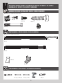 6
6
-
 7
7
-
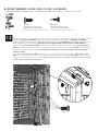 8
8
-
 9
9
-
 10
10
-
 11
11
-
 12
12
-
 13
13
-
 14
14
-
 15
15
-
 16
16
-
 17
17
-
 18
18
-
 19
19
-
 20
20
-
 21
21
-
 22
22
-
 23
23
-
 24
24
-
 25
25
-
 26
26
-
 27
27
-
 28
28
-
 29
29
-
 30
30
-
 31
31
-
 32
32
-
 33
33
-
 34
34
-
 35
35
-
 36
36
-
 37
37
-
 38
38
-
 39
39
-
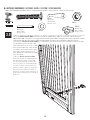 40
40
-
 41
41
-
 42
42
-
 43
43
-
 44
44
-
 45
45
-
 46
46
-
 47
47
-
 48
48
-
 49
49
-
 50
50
-
 51
51
-
 52
52
-
 53
53
-
 54
54
-
 55
55
-
 56
56


en otros idiomas
- français: Lifetime 60011 Le manuel du propriétaire
- English: Lifetime 60011 Owner's manual
Artículos relacionados
-
Lifetime 60429 El manual del propietario
-
-
Lifetime 60138 El manual del propietario
-
Lifetime 60127 El manual del propietario
-
-
-
-
-