
Precauciones
•Esta unidad ha sido diseñada para alimentarse
con cc 12 V, negativo a masa, solamente.
•No coloque los cables debajo de ningún tornillo,
ni los aprisione con partes móviles (p. ej. los raíles
del asiento).
•Antes de realizar las conexiones, desactive el
encendido del automóvil para evitar
cortocircuitos.
•Conecte los cables de entrada de alimentación
amarillo y rojo solamente después de haber
conectado los demás.
•Conecte todos los conductores de puesta a
masa a un punto común.
•Por razones de seguridad, asegúrese de aislar con
cinta aislante los cables sueltos que no estén
conectados.
Notas sobre el cable de suministro de
alimentación (amarillo)
•Cuando conecte esta unidad en combinación con
otros componentes estéreo, la capacidad nominal
del circuito conectado del automóvil debe ser
superior a la suma del fusible de cada
componente.
•Si no hay circuitos del automóvil con capacidad
nominal suficientemente alta, conecte la unidad
directamente a la batería.
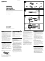
Lista de componentes (1)
•Los números de la lista corresponden a los de las
instrucciones.
•La unidad se comercializa con el soporte 1 y el
marco de protección 5 instalados. Antes de
montarla, utilice las llaves de liberación 7 para
extraer el soporte 1 y el marco de protección 5.
Para obtener más información, consulte
“Extracción del marco de protección y del soporte
(4)” en el reverso de la hoja.
•Conserve las llaves de liberación 7 para
utilizarlas en el futuro, ya que también las
necesitará si retira la unidad del automóvil.
Cautions
•This unit is designed for negative earth 12 V DC
operation only.
•Do not get the wires under a screw, or caught in
moving parts (e.g. seat railing).
•Before making connections, turn the car ignition
off to avoid short circuits.
•Connect the yellow and red power input leads
only after all other leads have been connected.
•Run all earth wires to a common earth point.
•Be sure to insulate any loose unconnected wires
with electrical tape for safety.
Notes on the power supply cord (yellow)
•When connecting this unit in combination with
other stereo components, the connected car
circuit’s rating must be higher than the sum of
each component’s fuse.
•When no car circuits are rated high enough,
connect the unit directly to the battery.
Parts Iist (1)
•The numbers in the list are keyed to those in the
instructions.
•The bracket 1 and the protection collar 5 are
attached to the unit before shipping. Before
mounting the unit, use the release keys 7 to
remove the bracket 1 and the protection collar
5 from the unit. For details, see “Removing the
protection collar and the bracket (4)” on the
reverse side of the sheet.
•Keep the release keys 7 for future use as they
are also necessary if you remove the unit from
your car.
Caution
Handle the bracket 1 carefully to avoid injuring
your fingers.
Note
Before installing, make sure that the catches on both
sides of the bracket 1 are bent inwards 2 mm. If the
catches are straight or bent outwards, the unit will not
be installed securely and may spring out.
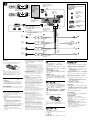
Connection example (2)
Notes (2-B- )
• Be sure to connect the earth cord before connecting
the amplifier.
• If you connect an optional power amplifier and do
not use the built-in amplifier, the beep sound will be
deactivated.
Tip (2-B-
)
For connecting two or more CD/MD changers, the
source selector XA-C30 (optional) is necessary.
Connection diagram (3)
1 To a metal surface of the car
First connect the black earth lead, then connect the
yellow and red power input leads.
2 To the power aerial control lead or power supply
lead of aerial booster amplifier
Notes
• It is not necessary to connect this lead if there is no
power aerial or aerial booster, or with a manually-
operated telescopic aerial.
• When your car has a built-in FM/AM aerial in the
rear/side glass, see “Notes on the control and
power supply leads.”
3 To AMP REMOTE IN of an optional power amplifier
This connection is only for amplifiers. Connecting
any other system may damage the unit.
4 To the +12 V power terminal which is energised in
the accessory position of the ignition key switch
Notes
• If there is no accessory position, connect to the +12
V power (battery) terminal which is energised at
all times.
Be sure to connect the black ground lead to a
metal surface of the car first.
• When your car has a built-in FM/AM aerial in the
rear/side glass, see “Notes on the control and
power supply leads.”
5 To the +12 V power terminal which is energised at
all times
Be sure to connect the black ground lead to a metal
surface of the car first.
3-246-853-21 (1)
Installation/Connections
Instalación/ Conexiones
FM/AM
Cassette
Car Stereo
Sony Corporation © 2003 Printed in Malaysia
XR-CA360X
XR-CA360
B
A
BUS AUDIO IN
BUS CONTROL IN
AUDIO OUT
REAR
BUS AUDIO IN
BUS CONTROL IN
Source selector*
Selector de fuente*
*
XA-CA30
1
*
not supplied
no suministrado
Catch
Notes on the control and power supply leads
• The power aerial control lead (blue) supplies +12 V
DC when you turn on the tuner.
• When your car has built-in FM/AM aerial in the rear/
side glass, connect the power aerial control lead
(blue) or the accessory power input lead (red) to the
power terminal of the existing aerial booster. For
details, consult your dealer.
•A power aerial without relay box cannot be used with
this unit.
Memory hold connection
When the yellow power input lead is connected, power
will always be supplied to the memory circuit even
when the ignition key is turned off.
Notes on speaker connection
• Before connecting the speakers, turn the unit off.
• Use speakers with an impedance of 4 to 8 ohms, and
with adequate power handling capacities to avoid its
damage.
• Do not connect the speaker terminals to the car
chassis, or connect the terminals of the right speakers
with those of the left speaker.
• Do not connect the earth lead of this unit to the
negative (–) terminal of the speaker.
• Do not attempt to connect the speakers in parallel.
• Connect only passive speakers. Connecting active
speakers (with built-in amplifiers) to the speaker
terminals may damage the unit.
• To avoid a malfunction, do not use the built-in
speaker wires installed in your car if the unit shares a
common negative (–) lead for the right and left
speakers.
• Do not connect the unit’s speaker cords to each other.
1
2
× 4
3
7
56
× 2
4
1
2

BUS
AUDIO IN
AUDIO
OUT
BUS AUDIO IN
BUS
CONTROL IN
AUDIO
OUT REAR
Supplied with XA-C30
Suministrado con el XA-C30
from car aerial
de antena de automóvil
Source selector
(not supplied )
Selector de fuente
(no suministrado )
XA-C30
1
4
5
2
AMP REM
ANT REM
6
RCA pin cord (not supplied)
Cable con clavijas RCA (no suministrado)
Max. supply current 0.3 A
Corriente máx. de alimentación de 0,3 A
Max. supply current 0.1 A
Corriente máx. de alimentación de 0,1 A
Fuse (10 A)
Fusible (10 A)
Red
Rojo
Yellow
Amarillo
Black
Negro
Blue
Azul
Blue/white striped
Con raya azul/blanca
White
Blanco
Green
Verde
Purple
Púrpura
White/black striped
Con raya blanca/negra
Grey/black striped
Con raya gris/negra
Green/black striped
Con raya verde/negra
Purple/black striped
Con raya violeta/negra
Grey
Gris
3
Left
Izquierdo
Right
Derecho
Left
Izquierdo
Right
Derecho
1
Supplied with the CD/MD changer
Suministrado con el cambiador de CD/MD
4 Al terminal de alimentación de +12 V que recibe
energía en la posición de accesorios del interruptor
de la llave de encendido
Notas
• Si no hay posición de accesorios, conéctelo al
terminal de alimentación (batería) de +12 V que
recibe energía sin interrupción.
Asegúrese de conectar primero el cable de tierra
negro a una superficie metálica del automóvil.
• Si el automóvil incorpora una antena de FM/AM en
el cristal trasero o lateral, consulte “Notas sobre los
cables de control y de fuente de alimentación”.
5 Al terminal de alimentación de +12 V que recibe
energía sin interrupción
Asegúrese de conectar primero el cable de tierra
negro a una superficie metálica del automóvil.
Notas sobre los cables de control y de fuente de
alimentación
• El conductor de control de la antena motorizada
(azul) suministrará + cc 12 V cuando conecte la
alimentación del sintonizador.
• Si el automóvil dispone de una antena de FM/AM
incorporada en el cristal trasero o lateral, conecte el
cable de control de antena motorizada (azul) o el
cable de entrada de alimentación auxiliar (rojo) al
terminal de alimentación del amplificador de antena
existente. Para obtener información detallada,
consulte a su distribuidor.
• Con esta unidad no es posible utilizar una antena
motorizada sin caja de relé.
Conexión para protección de la memoria
Si conecta el conductor de entrada amarillo, el circuito
de la memoria recibirá siempre alimentación, aunque
ponga la llave de encendido en la posición OFF.
Notas sobre la conexión de los altavoces
• Antes de conectar los altavoces, desconecte la
alimentación de la unidad.
• Utilice altavoces con una impedancia de 4 a 8 Ω , y
con la potencia máxima admisible adecuada, ya que
de lo contrario podría dañarlos.
• No conecte los terminales del sistema de altavoces al
chasis del automóvil, ni los del altavoz izquierdo a los
del derecho.
• No conecte el cable a masa de esta unidad al terminal
negativo (–) del altavoz.
• No intente conectar los altavoces en paralelo.
• No conecte altavoces activos (con amplificadores
incorporados) a los terminales de altavoces de la
unidad. Si lo hiciese, podría dañar tales altavoces. Por
lo tanto, cerciórese de conectar altavoces pasivos a
estos terminales.
• Para evitar fallos de funcionamiento, no utilice los
cables de altavoz incorporados instalados en el
automóvil si su unidad comparte un cable negativo
común (–) para los altavoces derecho e izquierdo.
• No conecte los cables de altavoz de la unidad entre sí.
1
Precaución
Tenga mucho cuidado al manipular el soporte 1
para evitar posibles lesiones en los dedos.
Nota
Antes de instalar la unidad, compruebe que los
enganches de ambos lados del soporte 1 están
doblados hacia adentro 2 mm. Si no lo están o están
doblados hacia afuera, la unidad no se instalará
correctamente y puede saltar.
Ejemplo de conexiones (2)
Notas (2-B- )
• Asegúrese de conectar primero el cable de puesta a
masa antes de realizar la conexión al amplificador.
• Si conecta un amplificador de potencia opcional y no
utiliza el incorporado, los pitidos se desactivarán.
Sugerencia (2-B-
)
Cuando desee conectar dos o más cambiadores de CD/
MD, necesitará un selector de fuente XA-C30 (opcional).
Diagramas de conexión (3)
1 A una superficie metálica del automóvil
Conecte primero el cable a masa negro, y después
los cables amarillo y rojo de entrada de
alimentación.
2 Al cable de control de la antena motorizada o al
cable de fuente de alimentación del amplificador de
antena
Notas
• Si no se dispone de antena motorizada ni de
amplificador de antena, o se utiliza una antena
telescópica accionada manualmente, no será
necesario conectar este cable.
• Si el automóvil incorpora una antena de FM/AM en
el cristal trasero o lateral, consulte “Notas sobre los
cables de control y de fuente de alimentación”.
3 A AMP REMOTE IN del amplificador de potencia
opcional
Esta conexión es sólo para amplificadores.
La conexión de cualquier otro sistema puede dañar
la unidad.
Enganche
Equipment used in illustrations
(not supplied)
Equipo utilizado en las ilustraciones
(no suministrado)
Front speaker
Altavoces delanteros
Rear speaker
Altavoces traseros
Power amplifier
Amplificador de potencia
CD/MD changer
Cambiador de CD/MD
•
•
•
•
•
•
•
•
1
•
• 1 5
7
1 5
4
•
7
1
1
2
2
•
•
2
3
1
2
•
•
3
4
•
•
5
•
•
•
•
•
•
•
•
•
•
•
3

1
2
5
7
7
c
c
c
1
Orient the release key
correctly.
Oriente la llave de
liberación en la dirección
correcta.
4
Face the hook inwards.
El gancho debe
encontrarse en la parte
interior.
A
to dashboard/centre console
al salpicadero/consola central
Bracket
Soporte
Bracket
Soporte
max. size
5 × 8 mm
Tamaño máx.
5 × 8mm
B
4
max. size
5 × 8 mm
Tamaño máx.
5 × 8mm
TOYOTA NISSAN
4
to dashboard/centre console
al salpicadero/consola central
Bracket
Soporte
Bracket
Soporte
4
Existing parts supplied with your car
Piezas existentes suministradas con su automóvil
Existing parts supplied with your car
Piezas existentes suministradas con su automóvil
max. size
5 × 8 mm
Tamaño máx.
5 × 8mm
max. size
5 × 8 mm
Tamaño máx.
5 × 8mm
4
182 mm
53 mm
1
2
3
1
2
Dashboard
Salpicadero
5
AB
(OFF)
(RELEASE)
Fire wall
Panel cortafuegos
Claws
Uñas
3
B
A
5
6
7
1

Precauciones
•Elija cuidadosamente el lugar de montaje de forma que la unidad
no interfiera las funciones normales de conducción.
•Evite instalar la unidad donde pueda quedar sometida a altas
temperaturas, como a la luz solar directa o al aire caliente de
calefacción, o a polvo, suciedad o vibraciones excesivas.
•Para realizar una instalación segura y firme, utilice solamente la
ferretería de montaje suministrada.
Ajuste del ángulo de montaje
Ajuste el ángulo de montaje a menos de 20°.
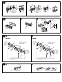
Extracción del marco de protección y del
soporte (4)
Antes de instalar la unidad, retire el marco de protección 5 y el
soporte 1 de la misma.
1 Retire el marco de protección 5.
1 Una las llaves de liberación 7 al marco de protección 5.
2 Retire la llave de liberación 7 para extraer el marco de
protección 5.
2 Retire el soporte 1.
1 Inserte ambas llaves de liberación 7 entre la unidad y el
soporte hasta que encajen.
2 Presione el soporte 1 y, a continuación, levante la unidad para
separar ambos elementos.
Selector de frecuencia
El intervalo de sintonía de AM (FM) ha sido ajustado en fábrica a la
posición 9 k (50 k). Si el sistema de asignación de frecuencias de su
país se basa en el intervalo de 10 kHz (200 kHz), ponga este selector,
situado en la base de la unidad, en la 10 k (200 k) antes de realizar las
conexiones.
Ejemplo de montaje (5)
Instalación en el salpicadero
Notas
• Si es necesario, doble estas uñas hacia afuera para que encaje
firmemente. (5-2).
• Compruebe que los 4 enganches del marco de protección 5 estén bien
fijados en las ranuras de la unidad. (5-3).
Montaje de la unidad en un automóvil
japonés (6)
Usted no podrá instalar esta unidad en algunos automóviles
japoneses. En tal caso, consulte a su distribuidor Sony.
Nota
Para evitar que se produzcan fallos, realice la instalación solamente con los
tornillos suministrados 4.
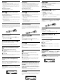
Forma de extraer e instalar el panel frontal
(7)
Antes de instalar la unidad, extraiga el panel frontal.
7-A Para extraerlo
Antes de extraer el panel frontal, ceriórese de presionar (OFF).
Después presione (RELEASE), deslícelo hacia la izquierda, y por
último tire de él hacia usted.
7-B Para instalarlo
Coloque el orificio A del panel frontal en el eje B de la unidad,
como se muestra en la ilustración, y después presione la parte
izquierda hasta que encaje.
Advertencia sobre la instalación en un
automóvil que no disponga de posición ACC
(accesorios) en el interruptor de la llave de
encendido
Asegúrese de presionar (OFF) en la unidad durante dos
segundos para desactivar la indicación del reloj después de
apagar el motor.
Si presiona (OFF) sólo momentáneamente, la indicación del reloj no
se desactivará y esto causará el desgaste de la batería.
Botón RESET
Una vez finalizada la instalación y las conexiones, desmonte el panel
frontal y presione el botón RESET con un bolígrafo o un objeto
similar.
Precautions
•Choose the installation location carefully so that the unit will not
interfere with normal driving operations.
•Avoid installing the unit in areas subject to dust, dirt, excessive
vibration, or high temperatures, such as in direct sunlight or near
heater ducts.
•Use only the supplied mounting hardware for a safe and secure
installation.
Mounting angle adjustment
Adjust the mounting angle to less than 20°.
Removing the protection collar and the
bracket (4)
Before installing the unit, remove the protection collar 5 and
the bracket 1 from the unit.
1 Remove the protection collar 5.
1 Engage the release keys 7 together with the protection collar
5 .
2 Pull out the release keys 7 to remove the protection collar 5.
2 Remove the bracket 1.
1 Insert both release keys 7 together between the unit and the
bracket until they click.
2 Pull down the bracket 1, then pull up the unit to separate.
Frequency select switch
The AM (FM) tuning interval is factory-set to the 9 k (50 k) position.
If the frequency allocation system of your country is based on 10 kHz
(200 kHz) interval, set the switch on the bottom of the unit to the 10 k
(200 k) position before making connections.
Mounting example (5)
Installation in the dashboard
Notes
• Bend these claws outward for a tight fit, if necessary (5-2).
• Make sure that the 4 catches on the protection collar 5 are properly
engaged in the slots of the unit (5-3).
Mounting the unit in a Japanese car (6)
You may not be able to install this unit in some makes of Japanese
cars. In such a case, consult your Sony dealer.
Note
To prevent malfunction, install only with the supplied screws 4.
How to detach and attach the front panel
(7)
Before installing the unit, detach the front panel.
7-A To detach
Before detaching the front panel, be sure to press (OFF).
Press (RELEASE), then slide the front panel to the left, and pull it off
towards you.
7-B To attach
Attach part A of the front panel to part B of the unit as illustrated
and push the left side into position until it clicks.
Warning when installing in a car without ACC
(accessory) position on the ignition key
switch
Be sure to press (OFF) on the unit for two seconds to turn
off the clock display after turning off the engine.
When you press (OFF) only momentarily, the clock display does not
turn off and this causes battery wear.
RESET button
When the installation and connections are completed, be sure to
press the RESET button with a ballpoint pen, etc., after detaching the
front panel.
•
•
•
4
5 1
5
1 7 5
2 7 5
1
1 7
2 1
5
• 5
• 5 5
6
4
7
7
(OFF)
(RELEASE)
7
A B
(OFF)
(OFF)
Transcripción de documentos
3-246-853-21 (1) 1 5 4 FM/AM Cassette Car Stereo Installation/Connections 2 1 3 6 7 ×2 ×4 2 A Instalación/ Conexiones 安裝 線路連接 B BUS AUDIO IN BUS CONTROL IN AUDIO OUT REAR BUS AUDIO IN Source selector* Selector de fuente* 音源選擇器 * XR-CA360X XR-CA360 XA-CA30 Sony Corporation © 2003 Printed in Malaysia Cautions Connection example (2) •This unit is designed for negative earth 12 V DC operation only. •Do not get the wires under a screw, or caught in moving parts (e.g. seat railing). •Before making connections, turn the car ignition off to avoid short circuits. •Connect the yellow and red power input leads only after all other leads have been connected. •Run all earth wires to a common earth point. •Be sure to insulate any loose unconnected wires with electrical tape for safety. Notes (2-B- ) • Be sure to connect the earth cord before connecting the amplifier. • If you connect an optional power amplifier and do not use the built-in amplifier, the beep sound will be deactivated. Notes on the power supply cord (yellow) •When connecting this unit in combination with other stereo components, the connected car circuit’s rating must be higher than the sum of each component’s fuse. •When no car circuits are rated high enough, connect the unit directly to the battery. Parts Iist (1) •The numbers in the list are keyed to those in the instructions. •The bracket 1 and the protection collar 5 are attached to the unit before shipping. Before mounting the unit, use the release keys 7 to remove the bracket 1 and the protection collar 5 from the unit. For details, see “Removing the protection collar and the bracket (4)” on the reverse side of the sheet. •Keep the release keys 7 for future use as they are also necessary if you remove the unit from your car. Caution Handle the bracket 1 carefully to avoid injuring your fingers. 1 Catch Note Before installing, make sure that the catches on both sides of the bracket 1 are bent inwards 2 mm. If the catches are straight or bent outwards, the unit will not be installed securely and may spring out. Tip (2-B- ) For connecting two or more CD/MD changers, the source selector XA-C30 (optional) is necessary. Connection diagram (3) 1 To a metal surface of the car First connect the black earth lead, then connect the yellow and red power input leads. 2 To the power aerial control lead or power supply lead of aerial booster amplifier Notes • It is not necessary to connect this lead if there is no power aerial or aerial booster, or with a manuallyoperated telescopic aerial. • When your car has a built-in FM/AM aerial in the rear/side glass, see “Notes on the control and power supply leads.” 3 To AMP REMOTE IN of an optional power amplifier This connection is only for amplifiers. Connecting any other system may damage the unit. 4 To the +12 V power terminal which is energised in the accessory position of the ignition key switch Notes • If there is no accessory position, connect to the +12 V power (battery) terminal which is energised at all times. Be sure to connect the black ground lead to a metal surface of the car first. • When your car has a built-in FM/AM aerial in the rear/side glass, see “Notes on the control and power supply leads.” 5 To the +12 V power terminal which is energised at all times Be sure to connect the black ground lead to a metal surface of the car first. * not supplied no suministrado 非附送 BUS CONTROL IN Notes on the control and power supply leads • The power aerial control lead (blue) supplies +12 V DC when you turn on the tuner. • When your car has built-in FM/AM aerial in the rear/ side glass, connect the power aerial control lead (blue) or the accessory power input lead (red) to the power terminal of the existing aerial booster. For details, consult your dealer. • A power aerial without relay box cannot be used with this unit. Memory hold connection When the yellow power input lead is connected, power will always be supplied to the memory circuit even when the ignition key is turned off. Notes on speaker connection • Before connecting the speakers, turn the unit off. • Use speakers with an impedance of 4 to 8 ohms, and with adequate power handling capacities to avoid its damage. • Do not connect the speaker terminals to the car chassis, or connect the terminals of the right speakers with those of the left speaker. • Do not connect the earth lead of this unit to the negative (–) terminal of the speaker. • Do not attempt to connect the speakers in parallel. • Connect only passive speakers. Connecting active speakers (with built-in amplifiers) to the speaker terminals may damage the unit. • To avoid a malfunction, do not use the built-in speaker wires installed in your car if the unit shares a common negative (–) lead for the right and left speakers. • Do not connect the unit’s speaker cords to each other. Precauciones •Esta unidad ha sido diseñada para alimentarse con cc 12 V, negativo a masa, solamente. •No coloque los cables debajo de ningún tornillo, ni los aprisione con partes móviles (p. ej. los raíles del asiento). •Antes de realizar las conexiones, desactive el encendido del automóvil para evitar cortocircuitos. •Conecte los cables de entrada de alimentación amarillo y rojo solamente después de haber conectado los demás. •Conecte todos los conductores de puesta a masa a un punto común. •Por razones de seguridad, asegúrese de aislar con cinta aislante los cables sueltos que no estén conectados. Notas sobre el cable de suministro de alimentación (amarillo) •Cuando conecte esta unidad en combinación con otros componentes estéreo, la capacidad nominal del circuito conectado del automóvil debe ser superior a la suma del fusible de cada componente. •Si no hay circuitos del automóvil con capacidad nominal suficientemente alta, conecte la unidad directamente a la batería. Lista de componentes (1) •Los números de la lista corresponden a los de las instrucciones. •La unidad se comercializa con el soporte 1 y el marco de protección 5 instalados. Antes de montarla, utilice las llaves de liberación 7 para extraer el soporte 1 y el marco de protección 5. Para obtener más información, consulte “Extracción del marco de protección y del soporte (4)” en el reverso de la hoja. •Conserve las llaves de liberación 7 para utilizarlas en el futuro, ya que también las necesitará si retira la unidad del automóvil. 3 Supplied with the CD/MD changer Suministrado con el cambiador de CD/MD 附帶於 CD/MD 換碟機 Source selector (not supplied ) Selector de fuente (no suministrado ) 音源選擇器 (非附送) Equipment used in illustrations (not supplied) Equipo utilizado en las ilustraciones (no suministrado) 插圖中的裝置 (非附送) Supplied with XA-C30 Suministrado con el XA-C30 附帶於 XA-C30 Fuse (10 A) Fusible (10 A) 保險絲(10 A) XA-C30 Front speaker Altavoces delanteros 前揚聲器 BUS CONTROL IN Rear speaker Altavoces traseros 後揚聲器 BUS AUDIO IN from car aerial de antena de automóvil 來自汽車天線 BUS AUDIO IN Power amplifier Amplificador de potencia 功率放大器 AUDIO OUT AUDIO OUT REAR RCA pin cord (not supplied) Cable con clavijas RCA (no suministrado) RCA 針型插頭電線(非附送) AMP REM CD/MD changer Cambiador de CD/MD CD/MD 換碟機 Blue/white striped Con raya azul/blanca 藍 白條紋 6 3 Max. supply current 0.3 A Corriente máx. de alimentación de 0,3 A 最大供電量 0.3 A Left Izquierdo 左 Right Derecho 右 Left Izquierdo 左 Right Derecho 右 Precaución Tenga mucho cuidado al manipular el soporte 1 para evitar posibles lesiones en los dedos. 1 Enganche Nota Antes de instalar la unidad, compruebe que los enganches de ambos lados del soporte 1 están doblados hacia adentro 2 mm. Si no lo están o están doblados hacia afuera, la unidad no se instalará correctamente y puede saltar. Ejemplo de conexiones (2) Notas (2-B- ) • Asegúrese de conectar primero el cable de puesta a masa antes de realizar la conexión al amplificador. • Si conecta un amplificador de potencia opcional y no utiliza el incorporado, los pitidos se desactivarán. Sugerencia (2-B- ) Cuando desee conectar dos o más cambiadores de CD/ MD, necesitará un selector de fuente XA-C30 (opcional). Diagramas de conexión (3) 1 A una superficie metálica del automóvil Conecte primero el cable a masa negro, y después los cables amarillo y rojo de entrada de alimentación. 2 Al cable de control de la antena motorizada o al cable de fuente de alimentación del amplificador de antena Notas • Si no se dispone de antena motorizada ni de amplificador de antena, o se utiliza una antena telescópica accionada manualmente, no será necesario conectar este cable. • Si el automóvil incorpora una antena de FM/AM en el cristal trasero o lateral, consulte “Notas sobre los cables de control y de fuente de alimentación”. 3 A AMP REMOTE IN del amplificador de potencia opcional Esta conexión es sólo para amplificadores. La conexión de cualquier otro sistema puede dañar la unidad. White Blanco 白色 Black Negro 黑色 White/black striped Con raya blanca/negra 白 黑條紋 Grey Gris 灰色 Blue Azul 藍色 1 Grey/black striped Con raya gris/negra 灰 黑條紋 Red Rojo 紅色 Green Verde 綠色 ANT REM Max. supply current 0.1 A Corriente máx. de alimentación de 0,1 A 最大供電量 0.1 A 2 4 Green/black striped Con raya verde/negra 綠 黑條紋 Purple Púrpura 紫色 Yellow Amarillo 黃色 5 Purple/black striped Con raya violeta/negra 紫 黑條紋 4 Al terminal de alimentación de +12 V que recibe energía en la posición de accesorios del interruptor de la llave de encendido Notas • Si no hay posición de accesorios, conéctelo al terminal de alimentación (batería) de +12 V que recibe energía sin interrupción. Asegúrese de conectar primero el cable de tierra negro a una superficie metálica del automóvil. • Si el automóvil incorpora una antena de FM/AM en el cristal trasero o lateral, consulte “Notas sobre los cables de control y de fuente de alimentación”. 5 Al terminal de alimentación de +12 V que recibe energía sin interrupción Asegúrese de conectar primero el cable de tierra negro a una superficie metálica del automóvil. Notas sobre los cables de control y de fuente de alimentación • El conductor de control de la antena motorizada (azul) suministrará + cc 12 V cuando conecte la alimentación del sintonizador. • Si el automóvil dispone de una antena de FM/AM incorporada en el cristal trasero o lateral, conecte el cable de control de antena motorizada (azul) o el cable de entrada de alimentación auxiliar (rojo) al terminal de alimentación del amplificador de antena existente. Para obtener información detallada, consulte a su distribuidor. • Con esta unidad no es posible utilizar una antena motorizada sin caja de relé. Conexión para protección de la memoria Si conecta el conductor de entrada amarillo, el circuito de la memoria recibirá siempre alimentación, aunque ponga la llave de encendido en la posición OFF. Notas sobre la conexión de los altavoces • Antes de conectar los altavoces, desconecte la alimentación de la unidad. • Utilice altavoces con una impedancia de 4 a 8 Ω , y con la potencia máxima admisible adecuada, ya que de lo contrario podría dañarlos. • No conecte los terminales del sistema de altavoces al chasis del automóvil, ni los del altavoz izquierdo a los del derecho. • No conecte el cable a masa de esta unidad al terminal negativo (–) del altavoz. • No intente conectar los altavoces en paralelo. • No conecte altavoces activos (con amplificadores incorporados) a los terminales de altavoces de la unidad. Si lo hiciese, podría dañar tales altavoces. Por lo tanto, cerciórese de conectar altavoces pasivos a estos terminales. • Para evitar fallos de funcionamiento, no utilice los cables de altavoz incorporados instalados en el automóvil si su unidad comparte un cable negativo común (–) para los altavoces derecho e izquierdo. • No conecte los cables de altavoz de la unidad entre sí. 注意 線路連接圖(3) •本機只能使用負極接地 12 V 直流電源。 •不要使導線夾在螺栓下,或繞掛在移動部件上 (如:座椅扶手上)。 •進行連接之前,請先關閉汽車的點火器,以避免短 路。 •黃色和紅色電源輸入導線必須在所有其它導線都連 接完畢以後才連接。 •將所有地線都連接到同一接地點。 •為了安全,請確認把沒有連接的導線用電器膠帶包 紮進行絕緣。 1 至汽車的金屬表面 首先連接黑色接地導線,然後再連接黃色和紅色電源輸入 導線。 2 至電動天線控制導線或天線升壓放大器的電源導線 註 • 如無電動天線,增壓器,或用手操作的套管式天線, 便不須連接此導線。 • 您汽車的後 側玻璃窗中如果內裝有 FM/AM 天線,即 請參看“控制和電源線須知”。 3 至選購的功率放大器的 AMP REMOTE IN(放大器遙控輸 入) 本連接僅用於放大器。連接任何其它系統可能會損壞本 機。 4 至在點火鑰匙的附件位置上通電的 +12 V 電源端子 註 • 若沒有附件位置,則請連接至始終通電的 +12 V 電源 (電池)端子。 必須首先將黑色接地導線連接至汽車的金屬表面。 • 您汽車的後 側玻璃窗中如果內裝有 FM/AM 天線,即 請參看“控制和電源線須知”。 5 至始終都通電的 +12 V 電源端子 必須首先將黑色接地導線連接至汽車的金屬表面。 電源導線須知(黃色) •將本機與其它立體聲裝置組合使用時,所連接的汽 車電路容量必須大於每個裝置保險絲容量的總和。 •當汽車電路容量不夠大時,請將本機直接與電池相 連接。 零件一覽表(1) •圖示數字與說明書中的數字是一致的。 • 托架 1 和保護環 5 在出廠之前已經裝在本裝 置上。在安裝本裝置之前,請先使用開鎖鑰匙 7 將托架 1 和保護環 5 從本裝置上拆下。詳細說 明,請參見本頁反面“拆下保護環和托架 (4)”。 • 如果今後要將本裝置從汽車上拆下,也要使用開鎖 鑰匙,因此請保存好開鎖鑰匙 7 以備今後使用。 控制和電源線須知 • 接通調諧器電源時,電動天線的控制導線(藍色)便能提供 +12 V 直流電。 • 若您的汽車後 側玻璃窗上有內置 FM/AM 天線,須將電動 天線控制導線(藍色)或輔助電源輸入導線(紅色)連接到 現有天線升壓器上的電源端子上。詳細內容請向銷售商諮 詢。 • 本機不能使用不具備繼電盒的電動天線。 注意 保持記憶的線路連接法 當連接好黃色電源輸入導線時,即使汽車發動機點火鑰匙關 閉,電源仍將對記憶電路供電。 移動托架 1 時,請特別注意別傷到手指。 1 拌鉤 註 安裝之前,必須將托架 1 兩側的拌鉤向內彎曲 2 mm 。如 果拌鉤筆直或向外彎曲,則本裝置將無法牢固安裝,並可能 彈出。 線路連接圖例(2) 註 (2-B- ) • 務必在接放大器之前連接地線。 • 如果您連接了選購的功率放大器而不使用內裝的放大器, 將無嘟聲功能。 要領(2-B- ) 若要連接 2 台或更多 CD/MD 換碟機時,必須使用音源選擇 器 XA-C30(選購件)。 連接揚聲器時的肴意事項 • 連接揚聲器電線以前,請先切斷本機電源。 • 使用阻抗為 4-8Ω 且具有充分功率處理容量的揚聲器,以 免損壞揚聲器。 • 不要將揚聲器端子連接到車身上或將右揚聲器端子與左揚 聲器端子相連接。 • 切勿將本機的接地導線連接至揚聲器的負(-)接線柱。 • 揚聲器不可以並聯連接。 • 請僅連接無源揚聲器。若將有源揚聲器(帶內置放大器)連 接到揚聲器端子上會損壞本機。 • 若本裝置使用左、右揚聲器的共用負極( - ) 導線,為了避 免故障,切勿使用已安裝在汽車內的內置揚聲器導線。 • 請勿將本裝置揚聲器導線相互連接。 41 2 7 7 5 c c c Orient the release key correctly. Oriente la llave de liberación en la dirección correcta. 正確定位開鎖鑰匙。 Face the hook inwards. El gancho debe encontrarse en la parte interior. 掛鉤朝裡面。 1 51 3 2 Dashboard Salpicadero 儀表板 Fire wall Panel cortafuegos 防火壁 1 182 mm 5 2 53 m m Claws Uñas 鉤爪 1 3 6A B TOYOTA NISSAN 4 4 max. size 5 × 8 mm Tamaño máx. 5 × 8 mm 最大尺寸 5×8 mm max. size 5 × 8 mm Tamaño máx. 5 × 8 mm 最大尺寸 5×8 mm to dashboard/centre console al salpicadero/consola central 至儀表板 中央控制箱 4 Bracket Soporte 托架 4 Bracket Soporte 托架 max. size 5 × 8 mm Tamaño máx. 5 × 8 mm 最大尺寸 5×8 mm Bracket Soporte 托架 (OFF) max. size 5 × 8 mm Tamaño máx. 5 × 8 mm 最大尺寸 5×8 mm Bracket Soporte 托架 Existing parts supplied with your car Piezas existentes suministradas con su automóvil 隨汽車附送的部件 Existing parts supplied with your car Piezas existentes suministradas con su automóvil 隨汽車附送的部件 7A to dashboard/centre console al salpicadero/consola central 至儀表板 中央控制箱 B A B (RELEASE) Precautions Precauciones 使用前注意事項 •Choose the installation location carefully so that the unit will not interfere with normal driving operations. •Avoid installing the unit in areas subject to dust, dirt, excessive vibration, or high temperatures, such as in direct sunlight or near heater ducts. •Use only the supplied mounting hardware for a safe and secure installation. •Elija cuidadosamente el lugar de montaje de forma que la unidad no interfiera las funciones normales de conducción. •Evite instalar la unidad donde pueda quedar sometida a altas temperaturas, como a la luz solar directa o al aire caliente de calefacción, o a polvo, suciedad o vibraciones excesivas. •Para realizar una instalación segura y firme, utilice solamente la ferretería de montaje suministrada. • 仔細選取安裝位置,以使本裝置不干擾正常的駕駛操作。 • 避免將本機安裝在受灰塵,污物和強烈振動影響的區域,或安裝在高 溫處,如直對陽光下或熱氣管道附近。 • 為了安裝安全和可靠,請使用附送的安裝構件。 Mounting angle adjustment Ajuste del ángulo de montaje Adjust the mounting angle to less than 20°. Ajuste el ángulo de montaje a menos de 20°. 安裝角度之調整 請在 20 度以內調整安裝角度。 拆下保護環和托架(4) 安裝之前,請先從本裝置上拆下保護環 5 和托架 1 。 Removing the protection collar and the bracket (4) Extracción del marco de protección y del soporte (4) Before installing the unit, remove the protection collar 5 and the bracket 1 from the unit. Antes de instalar la unidad, retire el marco de protección 5 y el soporte 1 de la misma. 1 Remove the protection collar 5. 1 Engage the release keys 7 together with the protection collar 5. 2 Pull out the release keys 7 to remove the protection collar 5. 1 Retire el marco de protección 5. 1 Una las llaves de liberación 7 al marco de protección 5. 2 Retire la llave de liberación 7 para extraer el marco de protección 5. 2 Remove the bracket 1. 1 Insert both release keys 7 together between the unit and the bracket until they click. 2 Pull down the bracket 1, then pull up the unit to separate. 2 Retire el soporte 1. 1 Inserte ambas llaves de liberación 7 entre la unidad y el soporte hasta que encajen. 2 Presione el soporte 1 y, a continuación, levante la unidad para separar ambos elementos. Frequency select switch The AM (FM) tuning interval is factory-set to the 9 k (50 k) position. If the frequency allocation system of your country is based on 10 kHz (200 kHz) interval, set the switch on the bottom of the unit to the 10 k (200 k) position before making connections. 1 拆下保護環 5 。 1 將開鎖鑰匙 7 與保護環 5 嚙合。 2 拉出開鎖鑰匙 7 以拆下保護環 5 。 2 拆下托架 1 。 1 將兩把開鎖鑰匙 7 一起插入裝置和托架之間,直至聽到喀嗒 聲。 2 向下拉托架 1 ,然後向上拉裝置,使之相互脫離。 頻率選擇開關 AM(FM)調諧間隔在出廠前被設定在 9 k(50 k) 位置上。若貴國的頻率 分配系統是以 10 kHz(200 kHz)間隔為基礎的,連接前,請將本機底 部上的開關設定在 10 k(200 k)位置上。 Selector de frecuencia El intervalo de sintonía de AM (FM) ha sido ajustado en fábrica a la posición 9 k (50 k). Si el sistema de asignación de frecuencias de su país se basa en el intervalo de 10 kHz (200 kHz), ponga este selector, situado en la base de la unidad, en la 10 k (200 k) antes de realizar las conexiones. 安裝示例(5) 安裝在儀錶板裡 註 • 若有必要,則可彎曲這些卡爪 (5-2)。 • 必須將保護環 5 上的 4個鉤爪正確嚙合在裝置的卡槽中。 (5-3)。 將本機安裝於日本產汽車上時(6) Mounting example (5) Installation in the dashboard Ejemplo de montaje (5) 有的日本產汽車不能安裝本機,在這種情形下,請您向當地的 Sony 經銷商諮詢。 Notes • Bend these claws outward for a tight fit, if necessary (5-2). • Make sure that the 4 catches on the protection collar 5 are properly engaged in the slots of the unit (5-3). Instalación en el salpicadero 註 為防止發生故障,安裝時只能使用附送的螺絲 4。 Notas • Si es necesario, doble estas uñas hacia afuera para que encaje firmemente. (5-2). • Compruebe que los 4 enganches del marco de protección 5 estén bien fijados en las ranuras de la unidad. (5-3). Mounting the unit in a Japanese car (6) You may not be able to install this unit in some makes of Japanese cars. In such a case, consult your Sony dealer. Note To prevent malfunction, install only with the supplied screws 4. How to detach and attach the front panel (7) 安裝本機之前,請先拆卸前板。 Montaje de la unidad en un automóvil japonés (6) Usted no podrá instalar esta unidad en algunos automóviles japoneses. En tal caso, consulte a su distribuidor Sony. Nota Para evitar que se produzcan fallos, realice la instalación solamente con los tornillos suministrados 4. Before installing the unit, detach the front panel. 7-A To detach Before detaching the front panel, be sure to press (OFF). Press (RELEASE), then slide the front panel to the left, and pull it off towards you. 7-B To attach Attach part A of the front panel to part B of the unit as illustrated and push the left side into position until it clicks. Forma de extraer e instalar el panel frontal (7) Antes de instalar la unidad, extraiga el panel frontal. 7-A Para extraerlo Antes de extraer el panel frontal, ceriórese de presionar (OFF). Después presione (RELEASE), deslícelo hacia la izquierda, y por último tire de él hacia usted. 7-B Warning when installing in a car without ACC (accessory) position on the ignition key switch Be sure to press (OFF) on the unit for two seconds to turn off the clock display after turning off the engine. When you press (OFF) only momentarily, the clock display does not turn off and this causes battery wear. RESET button When the installation and connections are completed, be sure to press the RESET button with a ballpoint pen, etc., after detaching the front panel. 如何拆卸和裝配前板(7) Para instalarlo Coloque el orificio A del panel frontal en el eje B de la unidad, como se muestra en la ilustración, y después presione la parte izquierda hasta que encaje. Advertencia sobre la instalación en un automóvil que no disponga de posición ACC (accesorios) en el interruptor de la llave de encendido Asegúrese de presionar (OFF) en la unidad durante dos segundos para desactivar la indicación del reloj después de apagar el motor. Si presiona (OFF) sólo momentáneamente, la indicación del reloj no se desactivará y esto causará el desgaste de la batería. Botón RESET Una vez finalizada la instalación y las conexiones, desmonte el panel frontal y presione el botón RESET con un bolígrafo o un objeto similar. 7-A 拆卸 拆卸前面板之前,須先按下 (OFF) 鍵。 按 (RELEASE) 鍵,然後將前面板滑向左側,並將其朝您的身體方向 拉出。 7-B 裝配 如圖所示,將前面板的 A 處對準本機的 B 處,然後將左側推入直 至聽到喀喳聲。 安裝在點火鑰匙開關上沒有 ACC(附件)位置 的汽車上時的警告 在關掉汽車引擎之後,一定請按下機器上的 (OFF) 兩秒以關 掉時鐘顯示。 如果只短暫地按一下 (OFF),將不會關掉時鐘顯示而浪費電池。 RESET 按鈕 當安裝和連接完成時,在除去前面板後必須用原子筆等工具按壓 RESET 按鈕。-
 1
1
-
 2
2
-
 3
3
-
 4
4


Sony XR-CA360X Guía de instalación
- Tipo
- Guía de instalación
- Este manual también es adecuado para
en otros idiomas
- English: Sony XR-CA360X Installation guide
Artículos relacionados
-
Sony XR-CA660X Guía de instalación
-
-
-
-
Sony CDX-S2000S Guía de instalación
-
-
-
-
-