Dell PowerEdge 2970 Guía del usuario

Tipo
Guía del usuario
Dell™ PowerEdge™ 2970
Information Update
Notes, Cautions, and Warnings
NOTE: A NOTE indicates important information that helps you make better use
of your computer.
CAUTION: A CAUTION indicates potential damage to hardware or loss of data
if instructions are not followed.
WARNING: A WARNING indicates a potential for property damage, personal
injury, or death.
____________________
Information in this document is subject to change without notice.
© 2007–2009 Dell Inc. All rights reserved.
Reproduction of these materials in any manner whatsoever without the written permission of Dell Inc.
is strictly forbidden.
Trademarks used in this text: Dell, the DELL logo, OpenManage, and PowerEdge are trademarks
of Dell Inc. Microsoft and Windows are registered trademarks of Microsoft Corporation in the United
States and/or other countries; Red Hat and Red Hat Enterprise Linux are registered trademarks
of Red Hat, Inc.; SUSE is a registered trademark of Novell Inc.; AMD PowerNow! is a trademark
of Advanced Micro Devices, Inc.
Other trademarks and trade names may be used in this document to refer to either the entities claiming
the marks and names or their products. Dell Inc. disclaims any proprietary interest in trademarks
and trade names other than its own.
November 2009 Rev. A06
Contents 3
Contents
Non-Optimal Memory Configurations . . . . . . . . . . . 5
Regional Hardware Owner’s Manuals
Available on the Web
. . . . . . . . . . . . . . . . . . . 5
Using the Online Diagnostics
. . . . . . . . . . . . . . . 5
System Setup Program Updates
. . . . . . . . . . . . . . 6
Memory Optimizer Technology Feature
. . . . . . . 6
QDMA Mode Feature
. . . . . . . . . . . . . . . . . 6
Demand-Based Power Management Feature
. . . . 6
Additional CPU Information
. . . . . . . . . . . . . . 6
Default Settings Update
. . . . . . . . . . . . . . . 7
System Start-up Behavior
. . . . . . . . . . . . . . . . . 7
Overcurrent Events on USB Ports
. . . . . . . . . . . . . 7
LCD Status Message Update
. . . . . . . . . . . . . . . 8
System Board Jumpers
. . . . . . . . . . . . . . . . . . 9
Creating a BMC User Password. . . . . . . . . . . . . 10
System Memory Update
. . . . . . . . . . . . . . . . . 11
4 Contents
3.5-Inch Chassis Update . . . . . . . . . . . . . . . . . 13
Front Features and Indicators
. . . . . . . . . . . 13
Mixed SAS/SATA Hard Drive Configuration
(3.5-Inch Drives Only)
. . . . . . . . . . . . . . . . 15
Removing a 3.5-Inch Drive Blank
. . . . . . . . . . 15
Installing a 3.5-Inch Drive Blank
. . . . . . . . . . 15
Removing the SAS/SATA Backplane Board
. . . . 16
Installing the SAS Backplane Board
. . . . . . . . 18
SAS/SATA Backplane Board Connectors
. . . . . 19
Information Update 5
Non-Optimal Memory Configurations
Memory configurations other than those listed in Table 3-1 and Table 3-2
of the Hardware Owner’s Manual are non-optimal configurations. The POST
may halt when a non-optimal memory configuration is detected and the
following message is displayed:
Non-Optimal Memory Configuration
Press F1 to continue or F2 for Setup
NOTE: Mixing DIMMs of different speeds renders the memory configuration
non-optimal. The system clocks down the performance to the slowest speed
in the DIMM set for the channel.
Regional Hardware Owner’s Manuals Available
on the Web
At production time, the translated regional versions of the Hardware Owner’s
Manual were unavailable for inclusion on the Dell OpenManage™
Documentation CD, version 5.2. All versions of the Hardware Owner’s
Manuals that are normally delivered on the CD are available for download
on the Web at support.dell.com.
Using the Online Diagnostics
The online Server Administrator Diagnostics tool mentioned in the section
"Using Server Administration Diagnostics" in the Hardware Owner’s Manual
has been replaced by the online Dell PowerEdge Diagnostics suite of
diagnostic programs. Dell PowerEdge Diagnostics includes online diagnostic
tests for chassis and storage components such as hard drives, physical
memory, communications ports, NICs, CMOS, and more.
To assess a system problem, first use the online Dell PowerEdge Diagnostics.
If you are unable to identify the problem using the PowerEdge Diagnostics,
then use the system diagnostics.
The files required to run PowerEdge Diagnostics for systems running
supported Microsoft
®
Windows
®
and Linux operating systems are available
at support.dell.com and on the CDs that came with your system. For
information about using diagnostics, see the Dell PowerEdge Diagnostics
User's Guide.
6 Information Update
System Setup Program Updates
Memory Optimizer Technology Feature
The current BIOS update provides a memory optimization feature on the
Memory Information screen of the System Setup Program. The Memory
Optimizer Technology option enables you to set the two DRAM controllers
to work independently in parallel 64-bit mode (Advanced ECC is not
available in this mode) or disable the feature to run the controllers in the
default 128-bit mode with Advanced ECC.
QDMA Mode Feature
On the Integrated Devices screen, a QDMA Mode option is now available for
the Embedded SATA field. When set to QDMA Mode, the embedded SATA
controller supports ATAPI devices at an increased data transfer rate than the
PIO rate that is supported in ATA Mode. A device driver must be installed
on your operating system to use QDMA Mode.
Demand-Based Power Management Feature
The Demand-Based Power Management option on the CPU Information
screen of the System Setup Program, which enables AMD PowerNow!™
technology features on your CPU(s), is not supported in Red Hat
®
Enterprise
Linux
®
operating systems prior to version 5.
SUSE
®
Linux Enterprise Server 10 fully supports demand-based power
management. SUSE Linux Enterprise Server 9 supports demand-based power
management on dual-core AMD processors, but not on the newer quad-core
processors.
Additional CPU Information
On the CPU Information screen, the processor fields now indicate the family,
model, and stepping of the specified processor.
Information Update 7
Default Settings Update
The following bullets are updates to information listed in your Hardware
Owner’s Manual.
•On the
Serial Communication
screen, the default setting for the
Serial
Communication
field is
On without Console Redirection
.
•On the
Serial Communication
screen, the default setting for the
Failsafe
Baud Rate
field is
115200
.
System Start-up Behavior
Note the following events that may occur on your system during start-up.
On systems with large memory configurations, the video monitor can take
from several seconds to approximately two minutes to display an image
at startup.
If you are running the Red Hat Enterprise Linux WS, ES, or AS
(Version 4) (x86-64) operating system, the system may display the
following on-screen message several times during start-up:
clear kernel mapping: mapping is split: will leak
memory
This message is specific to the operating system and does not indicate
a problem with your system hardware.
Overcurrent Events on USB Ports
Some USB devices can cause an overcurrent event on your system’s USB
ports. When this occurs, the system disables one or more of the affected USB
ports, and communication with the attached USB devices is lost. An on-
screen system message may appear noting the event, but this is not always
the case, particularly with devices connected to the rear USB ports. If an
overcurrent event disables your system’s USB ports, re-enable the ports by
restarting your system.
If overcurrent events persist, you may need to remove or replace the USB
device(s) connected to your system.
8 Information Update
LCD Status Message Update
Table 1-1 lists updates to the LCD status messages that can occur and the
probable cause for each message. The LCD messages refer to events recorded
in the system event log (SEL). For information on the SEL and configuring
systems management settings, see your systems management software
documentation.
Table 1-1. LCD Status Messages
Code Text Causes Corrective Actions
E1232 VDD 12V
PS# PwrGd
AC power was lost on
the specified power
supply while the system
was powered on. If AC
power was not lost, the
specified power supply
has failed.
If AC power was lost, this message
is information only. If the power
supply has failed, see "Getting
Help" in your Hardware Owner’s
Manual.
E141C CPU
Mismatch
The existing CPU
pairing in the system is
not supported.
Change the CPUs to a matched
pair or other valid configuration.
Information Update 9
System Board Jumpers
The jumper settings shown in Figure 6-1 and described in Table 6-1 of your
system’s Hardware Owner’s Manual are incorrect. The correct settings are
shown in Figure 1-1 and described in Table 1-2.
Figure 1-1. System Board Jumpers
10 Information Update
Creating a BMC User Password
You must assign a valid LAN user name and password before you can connect
to your system's Baseboard Management Controller (BMC) using the BMC
Management Utility. There are two methods of creating a LAN user name
and password:
If you access the BMC Remote Access Utility by pressing <CTRL+E>
during system startup, you can create a LAN user name, and a password
with up to 16 characters. (Note that only one LAN user name and
associated password can be created using this utility.) For information
on this option, see "Baseboard Management Controller Configuration" in
your
Dell OpenManage Baseboard Management Controller Utilities User’s
Guide
.
If you use the Deployment Toolkit SYSCFG.EXE utility, you can create a
LAN user name, and a password of up to 20 characters using the
syscfg
passwordaction
command. For more information, see "Configuring
New BMC Users" in the BMC
User’s Guide
.
Table 1-2. System Board Jumper Settings
Jumper Setting Description
NVRAM_CLR (default) The configuration settings are retained
at system boot.
The configuration settings are cleared at
the next system boot. (If the configuration
settings become corrupted to the point where
the system will not boot, install the jumper
and boot the system. Remove the jumper
before restoring the configuration
information.)
PWRD_EN
(default) The password feature is enabled.
The password feature is disabled.
Information Update 11
System Memory Update
The 8-GB DIMMs that are supported on your system are 533-MHz quad-rank
modules. All other sizes of supported DIMMs—512-MB, 1-GB, 2-GB, and
4-GB—are 667-MHz modules. Operating a system with a mix of 533-MHz
and 667-MHz DIMMs forces all DIMMs to operate at the slower 533-MHz
signal rate. Therefore, mixed memory configurations with 8-GB DIMMs are
not supported on your system and will result in an error message at startup
to indicate that the memory configuration is not optimal. Table 1-3 and
Table 1-4 provide updates to your system’s Hardware Owner’s Manual
regarding the currently supported system memory configurations and
memory sparing configurations.
Table 1-3. Memory Configurations
Total System Memory
CPU 1 Paired DIMMs
(Size Per DIMM)
CPU 2 Paired DIMMs
(Size Per DIMM)
1 CPU 2 CPUs DIMM 1/2 DIMM 3/4 DIMM 5/6 DIMM7/8
1 GB 2 GB 512 MB 512 MB
2 GB 4 GB 512 MB 512 MB 512 MB 512 MB
2 GB 4 GB 1 GB 1 GB
3 GB 6 GB 1 GB 512 MB 1 GB 512 MB
4 GB 8 GB 1 GB 1 GB 1 GB 1 GB
4 GB 8 GB 2 GB 2 GB
5 GB 10 GB 2 GB 512 MB 2 GB 512 MB
6 GB 12 GB 2 GB 1 GB 2 GB 1 GB
8 GB 16 GB 2 GB 2 GB 2 GB 2 GB
8 GB 16 GB 4 GB 4 GB
9 GB 18 GB 4 GB 512 MB 4 GB 512 MB
10 GB 20 GB 4 GB 1 GB 1 GB 4 GB
12 GB 24 GB 4 GB 2 GB 2 GB 4 GB
16 GB 32 GB 4 GB 4 GB 4 GB 4 GB
16 GB 32 GB 8 GB 8 GB
32 GB 64 GB 8 GB 8 GB 8 GB 8 GB
12 Information Update
The 8-GB DIMMs that are supported on your system are quad-rank modules.
Using quad-rank DIMMs in a memory sparing configuration provides a
proportionally smaller amount of spared memory than using single- or dual-
rank DIMMs in a similar configuration. Because memory sparing allocates
spared memory by DIMM ranks, one-fourth of a quad-rank DIMM (one rank
out of four) is spared instead of one-half of a dual-rank DIMM or the full
capacity of a single-rank DIMM. Table 1-4 supersedes the information
provided in your Hardware Owner’s Manual regarding memory sparing
configurations that are supported on your system.
Table 1-4. Memory Sparing in Single- and Dual-Processor Configurations
Processor 1 Processor 2 Available
Memory
Spared
Memory
DIMM
Pair 1/2
DIMM
Pair 3/4
DIMM
Pair 5/6
DIMM
Pair 7/8 1 CPU / 2 CPUs 1 CPU / 2 CPUs
512 MB
512 MB 512 MB 512 MB 1 GB / 2 GB 1 GB / 2 GB
1 GB 512 MB 1 GB 512 MB 1 GB / 2 GB 2 GB / 4 GB
1 GB
1 GB 1 GB 1 GB 2 GB / 4 GB 2 GB / 4 GB
2 GB 512 MB 2 GB 512 MB 3 GB / 6 GB 2 GB / 4 GB
2 GB
1 GB 2 GB 1 GB 4 GB / 8 GB 2 GB / 4 GB
2 GB
2 GB 2 GB 2 GB 6 GB / 12 GB 2 GB / 4 GB
4 GB 512 MB 4 GB 512 MB 5 GB / 10 GB 4 GB / 8 GB
4 GB 1 GB 4 GB 1 GB 6 GB / 12 GB 4 GB / 8 GB
4 GB 2 GB 4 GB 2 GB 8 GB / 16 GB 4 GB / 8 GB
4 GB
4 GB 4 GB 4 GB 12 GB / 24 GB 4 GB / 8 GB
8 GB 8 GB 8 GB 8 GB 28 GB / 56GB 4 GB / 8 GB
Indicates a spared single-rank DIMM (512-MB or 1-GB). The entire capacity
of this DIMM is reserved for sparing.
Indicates a spared dual-rank DIMM (2-GB or 4-GB). One-half of this DIMM’s
capacity is reserved for sparing.
8-GB DIMMs are quad-rank. One-fourth of this DIMM’s capacity is reserved
for sparing.
Information Update 13
3.5-Inch Chassis Update
Front Features and Indicators
Figure 1-2 and Table 1-5 identify the controls, indicators, and connectors
located behind the optional rack bezel on the system's front panel.
Figure 1-2. Front-Panel Features and Indicators
Table 1-5. Front-Panel LED Indicators, Buttons, and Connectors
Item Indicator, Button,
or Connector
Icon Description
1 Power-on indicator,
power button
The power-on indicator lights when
the system power is on.
The power button controls the DC power
supply output to the system.
NOTE: If you turn off the system using
the power button and the system is running
an ACPI-compliant operating system,
the system performs a graceful shutdown
before the power is turned off. If the system
is not running an ACPI-compliant operating
system, the power is turned off immediately
after the power button is pressed.
6
5
4
3
2
1
87
14 Information Update
2 NMI button Used to troubleshoot software and device
driver errors when using certain operating
systems. This button can be pressed using
the end of a paper clip.
Use this button only if directed to do so
by qualified support personnel or by the
operating system's documentation.
3 System
identification
button
The identification buttons on the front
and back panels can be used to locate a
particular system within a rack. When
one of these buttons is pushed, the LCD
panel on the front and the blue system
status indicator on the back blink until
one of the buttons is pushed again.
4 LCD panel Provides system ID, status information,
and system error messages.
The LCD lights during normal system
operation. Both the systems management
software and the identification buttons
located on the front and back of the
system can cause the LCD to flash blue
to identify a particular system.
The LCD lights amber when the system
needs attention, and the LCD panel
displays an error code followed by
descriptive text.
NOTE: If the system is connected to AC
power and an error has been detected, the
LCD lights amber regardless of whether the
system has been powered on.
5 USB connectors
(2)
Connects USB 2.0-compliant devices
to the system.
Table 1-5. Front-Panel LED Indicators, Buttons, and Connectors (continued)
Item Indicator, Button,
or Connector
Icon Description
Information Update 15
Mixed SAS/SATA Hard Drive Configuration (3.5-Inch Drives Only)
The 3.5-inch chassis allows two SATA hard drives to be mixed in the hard
drive bays with one to four SAS hard drives. The SAS/SATA configuration
must contain two SATA drives, which must be installed in drive bays 0 and 1.
The remaining drive bays (2 through 5) can only have SAS hard drives or drive
blanks installed.
Removing a 3.5-Inch Drive Blank
CAUTION: To maintain proper system cooling, all empty hard-drive bays must
have drive blanks installed. If you remove a hard-drive carrier from the system
and do not reinstall it, you must replace the carrier with a drive blank.
1
Remove the front bezel, if attached. See "Removing the Front Bezel"
in your
Hardware Owner’s Manual
.
2
Insert your finger under the shrouded end of the blank and press
in on the latch to eject the blank outward from the bay.
3
Pry the ends of the blank outward until the blank is free.
Installing a 3.5-Inch Drive Blank
The drive blank is keyed to ensure correct insertion into the drive bay.
To install a 3.5-inch drive blank, insert the keyed side of the blank into
the drive bay and press evenly on the other end of the blank until it is fully
inserted and latched.
6 Video connector Connects a monitor to the system.
7 Hard drives (6) Up to six 3.5-inch hot-plug hard drives.
8 Optical drive
(optional)
One optional slimline DVD drive.
Table 1-5. Front-Panel LED Indicators, Buttons, and Connectors (continued)
Item Indicator, Button,
or Connector
Icon Description
16 Information Update
Removing the SAS/SATA Backplane Board
WARNING: Only trained service technicians are authorized to remove the system
cover and access any of the components inside the system. See your Product
Information Guide for complete information about safety precautions, working
inside the computer, and protecting against electrostatic discharge.
1
Turn off the system and attached peripherals, and disconnect the system
from the electrical outlet.
2
Open the system. See "Opening the System" in your
Hardware Owner’s
Manual
.
3
Open the drive-carrier release handle on each hard drive and partially
extend all of the hard drives from their bays. See Figure 1-3.
NOTE: If you choose to remove the hard drives, be sure to record which hard
drive you remove from which bay. See "Removing a Hot-Plug Hard Drive"
in your Hardware Owner’s Manual.
Information Update 17
Figure 1-3. SAS/SATA Backplane Board Removal
4
If present, disconnect the optical drive power cable from the SAS/SATA
backplane board. See Figure 1-4 for the location of the optical drive power
connector.
5
Disconnect the SAS cable(s) from the backplane connectors.
See Figure 1-4 for the location of the SAS cable connectors.
6
If an optical drive is installed, disconnect the data cable from the back
of the optical drive.
7
If present, remove the storage controller daughter card. See "Removing
a SAS Controller Daughter Card" in your
Hardware Owner’s Manual
.
1 drive carrier 2 SAS backplane board
3 SAS-backplane board release pin
3
1
2
18 Information Update
8
Remove the SAS backplane board:
a
Pull the SAS-backplane board release pin. See Figure 1-3.
b
While pulling the release pin, tilt the backplane board toward the back
of the system.
c
Lift the backplane board from its securing tabs and remove
the backplane board from the chassis.
Installing the SAS Backplane Board
WARNING: Only trained service technicians are authorized to remove the system
cover and access any of the components inside the system. See your Product
Information Guide for complete information about safety precautions, working
inside the computer, and protecting against electrostatic discharge.
1
Place the SAS backplane board so that the securing tabs on the drive cage
are fully inserted into the securing slots on the backplane board.
See Figure 1-3.
2
Pull the SAS-backplane board release pin. See Figure 1-3.
3
While pulling the release pin, tilt the SAS backplane board toward the
front of the system until it stops, then release the release pin and ensure
that it snaps into place.
4
Reinstall the SAS controller daughter card. See "Installing a SAS
Controller Daughter Card" in your
Hardware Owner’s Manual
.
5
Reattach the SAS controller daughter card cables and the control panel
cable.
6
Reinsert the hard drives.
7
If applicable, reconnect the optical drive power cable to the backplane
board. See "Installing the Optical Drive" in your
Hardware Owner’s
Manual
.
8
Close the system. See "Closing the System" in your
Hardware Owner’s
Manual
.
Information Update 19
SAS/SATA Backplane Board Connectors
Figure 1-4 shows the location of the connectors on the SAS/SATA backplane
board.
Figure 1-4. SAS Backplane Board Components: 3.5-inch x4 Option
1 primary SAS (SAS_A) 2 optical drive power (CD_PWR)
3 secondary SAS (SAS_B) 4 drive 5 (SASDRV5)
5 backplane power (BP_PWR) 6 drive 4 (SASDRV4)
7 drive 3 (SASDRV3) 8 drive 2 (SASDRV2)
9 drive 1 (SASDRV1) 10 drive 0 (SASDRV0)
9
8
7
6
1
front
back
2
3
10
5
4
20 Information Update
Dell PowerEdge 2970
信息更新
注、小心和警告
注:“注”表示可以帮助您更好地使用计算机的重要信息。
小心:“小心”表示如果不遵循说明,就有可能损坏硬件
或导致数据丢失。
警告:“警告”表示可能会造成财产损失、人身伤害甚至死亡。
____________________
本说明文件中的信息如有更改,恕不另行通知。
© 2007
2009 Dell Inc.
版权所有,翻印必究。
未经
Dell Inc.
书面许可,严禁以任何形式复制这些材料。
本文中使用的商标:
Dell
DELL
徽标、
OpenManage
PowerEdge
Dell Inc.
的商标。
Microsoft
Windows
Microsoft Corporation
在美国和
/
或其它国家
/
地区的注册商标;
Red Hat
Red Hat Enterprise
Linux
Red Hat, Inc.
的注册商标;
SUSE
Novell Inc.
的注册商标;
AMD PowerNow!
Advanced Micro Devices, Inc.
的商标。
本说明文件中述及的其它商标和产品名称是指拥有相应商标和产品名称的公司或其制造
的产品。
Dell Inc.
对其它公司的商标和产品名称不拥有任何所有权。
2009
11
Rev. A06
目录 23
目录
非优化的内存配置 . . . . . . . . . . . . . . . . . . .
25
可以从相关
Web
站点上获取 硬件用户手册》
的区域版本
. . . . . . . . . . . . . . . . . . . . . . .
25
使用联机诊断
. . . . . . . . . . . . . . . . . . . . . .
25
系统设置程序更新
. . . . . . . . . . . . . . . . . . .
26
内存优化器技术功能
. . . . . . . . . . . . . . . 26
QDMA Mode QDMA 模式)功能
. . . . . . . . 26
Demand-Based Power Management
(基于需求的电源管理)功能
. . . . . . . . . . 26
其它 CPU 信息
. . . . . . . . . . . . . . . . . . . 26
默认设置更新
. . . . . . . . . . . . . . . . . . . 27
系统启动行为
. . . . . . . . . . . . . . . . . . . . . .
27
USB
端口上的过电流事件
. . . . . . . . . . . . . . .
27
LCD
状态信息更新
. . . . . . . . . . . . . . . . . . .
28
系统板跳线
. . . . . . . . . . . . . . . . . . . . . . .
29
创建
BMC
用户密码
. . . . . . . . . . . . . . . . . . .
30
系统内存更新
. . . . . . . . . . . . . . . . . . . . . .
31
24 目录
3.5
英寸机箱更新
. . . . . . . . . . . . . . . . . . . .
33
前面板部件和指示灯
. . . . . . . . . . . . . . . 33
混合 SAS/SATA 硬盘驱动器配置
(仅适用于 3.5 英寸驱动器)
. . . . . . . . . . . 34
卸下 3.5 英寸驱动器挡片
. . . . . . . . . . . . . 35
拆除 3.5 英寸驱动器挡片
. . . . . . . . . . . . . 35
卸下 SAS/SATA 背板
. . . . . . . . . . . . . . . . 35
安装 SAS 背板
. . . . . . . . . . . . . . . . . . . 37
SAS/SATA 背板连接器
. . . . . . . . . . . . . . . 38
信息更新 25
非优化的内存配置
除《硬件用户手册》表
3-1
3-2
中所列的配置之外,其它配置均属非优化
配置。如果检测到非优化的内存配置,
POST
会中止,并显示以下信息:
Non-Optimal Memory Configuration
(非优化的内存配置)
Press F1 to continue or F2 for Setup
(按
F1
继续,按
F2
进行设置)
注:将不同速率的
DIMM
混合使用会导致内存配置无法达到优化。
系统会将通道
DIMM
集的性能减为最慢速率。
可以从相关
Web
站点上获取《硬件用户手册》
的区域版本
在制作
5.2
版的《
Dell OpenManage
说明文件》
CD
时,尚未取得《硬件用
户手册》的区域翻译版本,因此这些版本未包括在该
CD
中。该
CD
上通常
会提供的所有《硬件用户手册》版本都能通过
support.dell.com
网站下载。
使用联机诊断
《硬件用户手册》的“使用服务器管理诊断程序”一节中所提到的在线服务
器管理员诊断程序工具已由诊断程序的
Dell PowerEdge
Diagnostics
联机套
件所取代。
Dell PowerEdge Diagnostics
包括用来检测机箱和存储组件(如硬
盘驱动器、物理内存、通信端口、
NIC
CMOS
等)的联机诊断检测。
要判定系统问题,请先使用联机的
Dell PowerEdge Diagnostics
。如果使用
PowerEdge Diagnostics
无法识别出问题,请使用系统诊断程序。
在运行支持的
Microsoft
®
Windows
®
Linux
操作系统的系统上运行
PowerEdge Diagnostics
所需的文件可以在
support.dell.com
上和系统附带的
CD
中找到。有关使用诊断程序的信息,请参阅
Dell PowerVault Diagnostics
User's Guide
Dell PowerEdge Diagnostics
用户指南)。
26 信息更新
系统设置程序更新
内存优化器技术功能
当前的
BIOS
更新在系统设置程序的
Memory Information
(内存信息)屏
幕上提供了内存优化功能。通过
Memory Optimizer Technology
(内存优化
技术)选项可以将两个
DRAM
控制器设置为在
64
位并行模式 (高级
ECC
在这种模式下不可用)下独立运行,或者禁用此功能,使控制器在默认的
128
位模式运行 (可运行高级
ECC
QDMA Mode
QDMA
模式)功能
Integrated Devices
(集成设备)屏幕中,现在提供了
QDMA Mode
QDMA
模式)选项,用于
Embedded SATA
(嵌入式
SATA
)字段。设置
QDMA Mode
QDMA
模式)后,嵌入式
SATA
控制器将使用比
ATA
Mode
ATA
模式)支持的
PIO
速率更快的数据传输速率支持
ATAPI
设备。
要使用
QDMA Mode
QDMA
模式),必须在操作系统上安装设备驱动
程序。
Demand-Based Power Management
(基于需求的电源管理)功能
系统设置程序的
CPU Information
CPU
信息)屏幕上的
Demand-Based
Power Management
(基于需求的电源管理)选项支持在
CPU
上使用
AMD PowerNow!
技术功能,但在第
5
版之前的
Red Hat
®
Enterprise
Linux
®
操作系统中不受支持。
SUSE
®
Linux Enterprise Server 10
全面支持基于需求的电源管理。
SUSE
Linux Enterprise Server 9
AMD
双核处理器上支持基于需求的电源管理,
但在较新的四核处理器上不支持这一功能。
其它
CPU
信息
现在,
CPU Information
CPU
信息)屏幕上的处理器字段会显示指定处理
器的系列、型号和步进。
信息更新 27
默认设置更新
下面的列表项内容是对《硬件用户手册》中所列信息的更新。
Serial Communication
(串行通信)屏幕中,
Serial Communication
(串行通信)字段的默认设置为
On without Console Redirection
(开,控制台重定向不启用)。
Serial Communication
(串行通信)屏幕中,
Failsafe Baud Rate
(故障保护波特率)字段的默认设置为
115200
系统启动行为
在启动系统的过程中,注意系统中可能发生的以下事件。
在启动带有大型内存配置的系统时,视频显示器可能需要几秒钟到大
约两分钟的时间才能显示
如果运行的是
Red Hat Enterprise Linux WS
ES
AS
(第
4
版)
(x86-64)
操作系统,系统在启动过程中可能会多次显示以下屏幕信息:
clear kernel mapping: mapping is split: will leak
memory
(清除内核映射:映射分散:将导致内存泄漏)
此信息特定于操作系统,不表示系统硬件出现故障。
USB
端口上的过电流事件
USB
设备可能会导致系统的
USB
端口发生过电事件。一发生这种
事件,系统将禁用一个或个受影响
USB
端口,时中止影响
USB
设备之间的通信。此时可能会显示系统屏幕信息,提示此事件,但是并不是
所有情况下都会显示此信息,其是在设备连接至背
USB
端口的
下。如果过电事件禁用了系统
USB
端口,可通过重新启动系统来重新
启用端口。
如果过电事件仍然存在,可能需要除或替换连接至系统的
USB
设备。
28 信息更新
LCD
状态信息更新
1-1
列出了可能出现的
LCD
状态信息的更新以及每则信息的可能因。
LCD
信息用系统事件日志
(SEL)
记录的事件。有关
SEL
和配置系统管
理设置的信息,请参阅系统管理件说明文件。
1-1. LCD
状态信息
代码 文本 原因 纠正措施
E1232 VDD 12V
PS# PwrGd
在系统通电的情况下,
指定电源设备上的
AC
电源中断。如果
AC
源没有中断,则说明指
定电源设备出现故障。
如果
AC
电源中断,则此信息仅
供参考。如果电源设备出现故
障,请参阅 《硬件用户手册》
中的 “获得帮助”
E141C CPU
Mismatch
系统中的现有
CPU
对不受支持。
CPU
更改为相匹配的对或其
它有效配置。
信息更新 29
系统板跳线
6-1
所示和《硬件用户手册》表
6-1
中所描述线设置均不正确
1-1
所示和表
1-2
中所描述的设置才是正确的设置。
1-1.
系统板跳线
30 信息更新
创建
BMC
用户密码
必须分配一个有
LAN
用户密码之后,才能使用
BMC
管理
程序连接到系统的底板管理控制器
(BMC)
创建
LAN
用户密码
有两种:
如果在系统启动过程中通过按
<CTRL+E>
访
BMC
访
程序,可以创建一个
LAN
用户和一个最长
16
个字
。(注意:使用此用程序,创建一个
LAN
用户和一个对
密码。)有关此选项的信息,请参阅《
Dell OpenManage
底板管理控制
用程序用户指南》中的“底板管理控制器配置”。
如果使用的是
Deployment Toolkit SYSCFG.EXE
用程序,可以使用
syscfg passwordaction
命令创建一个
LAN
用户和一个最长
20
个字密码有关更信息,请参阅
BMC
用户指南》中的
“配置新
BMC
用户”
1-2.
系统板跳线设置
跳线 设置 说明
NVRAM_CLR
(默认设置) 系统在引导时保留配置设置。
下一次系统引导时清除配置设置。
(如果配置设置被损坏以至于系统
不能进行引导,请安装跳线并引导系统。
恢复配置信息之前,请拔下跳线。
PWRD_EN
(默认设置) 已启用密码功能。
已禁用密码功能。
信息更新 31
系统内存更新
系统支持的
8 GB DIMM
属于
533 MHz 4
列模
DIMM
。支持的所有其它
DIMM
包括
512 MB
1 GB
2 GB
4 GB
,这些
DIMM
都属于
667 MHz
。如果运行时使用
533 MHz
667 MHz DIMM
的系统,
该系统会制所有
DIMM
都以较
533 MHz
的信号速率运行。所以,
使用
8 GB DIMM
混合内存配置在的系统上不受支持,在系统启动时,
会显示一条错误信息,指示内存配置未大到优化。
1-3
和表
1-4
是对系
统的《硬件用户手册》中有关当前支持的系统内存配置和内存备用配置信息
的更新。
1-3.
内存配置
总系统内存
CPU 1
配对
DIMM
(每个
DIMM
的大小)
CPU 2
配对
DIMM
(每个
DIMM
的大小)
CPU
CPU
DIMM 1/2 DIMM 3/4 DIMM 5/6 DIMM 7/8
1 GB 2 GB 512 MB 512 MB
2 GB 4 GB 512 MB 512 MB 512 MB 512 MB
2 GB 4 GB 1 GB 1 GB
3 GB 6 GB 1 GB 512 MB 1 GB 512 MB
4 GB 8 GB 1 GB 1 GB 1 GB 1 GB
4 GB 8 GB 2 GB 2 GB
5 GB 10 GB 2 GB 512 MB 2 GB 512 MB
6 GB 12 GB 2 GB 1 GB 2 GB 1 GB
8 GB 16 GB 2 GB 2 GB 2 GB 2 GB
8 GB 16 GB 4 GB 4 GB
9 GB 18 GB 4 GB 512 MB 4 GB 512 MB
10 GB 20 GB 4 GB 1 GB 1 GB 4 GB
12 GB 24 GB 4 GB 2 GB 2 GB 4 GB
16 GB 32 GB 4 GB 4 GB 4 GB 4 GB
16 GB 32 GB 8 GB 8 GB
32 GB 64 GB 8 GB 8 GB 8 GB 8 GB
32 信息更新
系统支持的
8 GB DIMM
属于
4
列模。在内存备用配置中使用
4
DIMM
所提供的备用内存容,在比相似配置中使用列或双列
DIMM
所提供的备用内存容。内存备用按
DIMM
列分配备用内存,所以一个
4
DIMM
的四分之一(四个列中的一个)将作为备用内存,不是将双
DIMM
的一
DIMM
的全作为备用。
1-4
将取代
《硬件用户手册》中有关系统支持的内存备用配置面的信息。
1-4.
单双处理配置中的内存备用
处理器
1
处理器
2
可用的内存 备用内存
DIMM
1/2
DIMM
3/4
DIMM
5/6
DIMM
7/8
CPU/
CPU
CPU/
CPU
512 MB
512 MB 512 MB 512 MB 1 GB / 2 GB 1 GB / 2 GB
1 GB 512 MB 1 GB 512 MB 1 GB / 2 GB 2 GB / 4 GB
1 GB
1 GB 1 GB 1 GB 2 GB / 4 GB 2 GB / 4 GB
2 GB 512 MB 2 GB 512 MB 3 GB / 6 GB 2 GB / 4 GB
2 GB
1 GB 2 GB 1 GB 4 GB / 8 GB 2 GB / 4 GB
2 GB
2 GB 2 GB 2 GB 6 GB / 12 GB 2 GB / 4 GB
4 GB 512 MB 4 GB 512 MB 5 GB / 10 GB 4 GB / 8 GB
4 GB 1 GB 4 GB 1 GB 6 GB / 12 GB 4 GB / 8 GB
4 GB 2 GB 4 GB 2 GB 8 GB / 16 GB 4 GB / 8 GB
4 GB
4 GB 4 GB 4 GB 12 GB / 24 GB 4 GB / 8 GB
8 GB 8 GB 8 GB 8 GB 28 GB / 56GB 4 GB / 8 GB
表示备用的单列
DIMM
512 MB
1 GB
)。
DIMM
的全部容量将保留用作
备用内存。
表示备用的双列
DIMM
2 GB
4 GB
。此
DIMM
容量的一半保留用
于备用。
8 GB DIMM
属于
4
列。此
DIMM
容量的四分之一保留用于备用。
信息更新 33
3.5
英寸机箱更新
前面板部件和指示灯
1-2
和表
1-5
识了系统前面上的可选机架挡板后面的控制按
指示连接器。
1-2.
前面板部件和指示灯
1-5.
前面板
LED
指示灯、按钮和连接器
项目 指示灯、按钮或
连接器
图标 说明
1
通电指示灯、
电源按钮
当系统接通电源时,通电指示灯
将亮起。
电源按钮控制对系统的直流电源输出。
注:如果使用电源按钮关闭系统,
并且系统运行的是
ACPI
兼容操作系统,
则系统可以在电源关闭之前从容关闭。
如果系统运行的不是
ACPI
兼容操作系
统,则按下电源按钮将立即关闭电源。
2
NMI
按钮 用于在使用某些操作系统时排除软件和
设备驱动程序错误。可以使用曲别针末
端按下此按钮。
只有获得合格支持人员指导,或者操作
系统说明文件中有相关指示,才可使用
此按钮。
6
5
4
3
2
1
87
34 信息更新
混合
SAS/SATA
硬盘驱动器配置(仅适用于
3.5
英寸驱动器)
3.5
英寸机箱允许在硬盘驱动器托架混合安装两个
SATA
硬盘驱动器和一
到四个
SAS
硬盘驱动器。
SAS/SATA
配置必须有两个
SATA
驱动器,
这两个驱动器必须安装在
0
1
号驱动器托架上。其它的驱动器托架
2
5
能安装
SAS
硬盘驱动器或驱动器挡片
3
系统识别按钮 前面板和背面板上的识别按钮可用于查
找机架中的特定系统。当按下其中一个
按钮时,系统前面板上的
LCD
面板和
后面板上的蓝色系统状态指示灯将闪
烁,直至再次按下其中一个按钮为止。
4
LCD
面板 用于提供系统
ID
、状态信息和系统错误
信息。
系统正常运行期间,
LCD
将亮起。
系统管理软件和位于系统前后面板的识
别按钮均可以导致
LCD
呈蓝色闪烁,
以识别特定的系统。
系统出现问题时,
LCD
面板呈琥珀色,
并且其中显示错误代码,后面是描述性
文字。
注:如果在系统已连接至交流电源时检
测到错误,则无论系统是否打开,
LCD
都将呈琥珀色亮起。
5
USB
连接器
2
个)
用于将
USB 2.0
兼容设备连接至系统。
6
视频连接器 用于将显示器连接至系统。
7
硬盘驱动器
6
个)
最多六个
3.5
英寸热插拔硬盘驱动器。
8
光盘驱动器
(可选)
一个可选的细长型
DVD
驱动器。
1-5.
前面板
LED
指示灯、按钮和连接器
(续)
项目 指示灯、按钮或
连接器
图标 说明
信息更新 35
卸下
3.5
英寸驱动器挡片
小心:为了维持正常的系统冷却,所有闲置的硬盘驱动器托架必须安装驱
动器挡片。如果从系统中卸下硬盘驱动器托盘而未将其装回,则必须用驱动
器挡片代替托盘安装到系统中。
1
下前挡板(如果已安装)。请参阅《硬件用户手册》中的“下前
挡板”。
2
将手指入到挡片导流端下,按下闩锁,使挡片弹托架
3
向外撬挡片的一端,直至挡片完脱离托架
拆除
3.5
英寸驱动器挡片
驱动器挡片定式的,可以保能够正确插入驱动器托架。如需安
3.5
英寸驱动器挡片,请将挡片边插入驱动器托架后均
压挡片一端,到其入并定。
卸下
SAS/SATA
背板
警告:
只有经过培训的维修技术人员才能卸下系统护盖并拆装系统内部的
各种组件。有关安全预防措施、拆装计算机内部组件以及防止静电损害的完
整信息,请参阅 《产品信息指南》
1
系统和连接的外设备,并断开系统电源插座连接
2
开系统护。请参阅《硬件用户手册》中的“开系统护”。
3
个硬盘驱动器上的驱动器释放,使所有硬盘驱动器的
托架。请参阅
1-3
注:如果选择卸下硬盘驱动器,则确保记录了从哪一个托架中卸下
了哪个硬盘驱动器。请参阅《硬件用户手册》中的“卸下热插拔硬盘
驱动器”。
36 信息更新
1-3.
卸下
SAS/SATA
背板
4
盘驱动器
SAS/SATA
背板之间的电源线(如果有)。
有关盘驱动器电源连接器的位置,请参阅
1-4
5
从背板连接器上
SAS
。有关
SAS
缆连接器的位置,
请参阅
1-4
6
如果已安装盘驱动器,请将数据线从光盘驱动器出。
7
除存储控制器子卡(如果有)。请参阅《硬件用户手册》
中的“
SAS
控制器子卡”。
8
SAS
背板
a
向外
SAS
背板释放销。请参阅
1-3
b
释放销时,向系统倾斜背板
c
背板从卡舌拉起机箱上下。
1
驱动器托盘
2
SAS
背板
3
SAS
背板
释放销
3
1
2
信息更新 37
安装
SAS
背板
警告:
只有经过培训的维修技术人员才能卸下系统护盖并拆装系统内部的
各种组件。有关安全预防措施、计算机内部操作以及防止静电损害的完
整信息,请参阅 《产品信息指南》
1
SAS
背板,使驱动器框架上的卡舌完背板上的
插槽内。请参阅
1-3
2
向外
SAS
背板释放销。请参阅
1-3
3
释放销时,将
SAS
背板向系统前方倾斜直至止,
放销保将其入到位。
4
重新安装
SAS
控制器子卡。请参阅《硬件用户手册》中的“安装
SAS
控制器子卡”。
5
重新连接
SAS
控制器子卡和控制面
6
重新入硬盘驱动器。
7
重新连接光盘驱动器和背板之间的电(如果有)。请参阅《硬件用
户手册》中的“安装盘驱动器”。
8
上系统护。请参阅《硬件用户手册》中的“上系统护”。
38 信息更新
SAS/SATA
背板连接器
1-4
显示了连接器在
SAS
背板上的所处位置。
1-4. SAS
背板连接组件:
3.5
英寸
x4
选项
1
主要
SAS (SAS_A)
2
可选驱动器电源
(CD_PWR)
3
辅助
SAS (SAS_B)
4
驱动器
5 (SASDRV5)
5
背板电源
(BP_PWR)
6
驱动器
4 (SASDRV4)
7
驱动器
3 (SASDRV3)
8
驱动器
2 (SASDRV2)
9
驱动器
1 (SASDRV1)
10
驱动器
0 (SASDRV0)
9
8
7
6
1
前面
背面
2
3
10
5
4
Dell™ PowerEdge™ 2970
Mise à jour
des informations
Remarques, précautions et avertissements
REMARQUE : une REMARQUE indique des informations importantes qui peuvent
vous aider à mieux utiliser votre ordinateur.
PRÉCAUTION : une PRÉCAUTION vous avertit d'un risque de dommage matériel
ou de perte de données en cas de non-respect des instructions données.
AVERTISSEMENT : un AVERTISSEMENT vous avertit d'un risque d'endom-
magement du matériel, de blessure corporelle ou de mort.
____________________
Les informations contenues dans ce document sont sujettes à modification sans préavis.
© 2007–2009 Dell Inc. Tous droits réservés.
La reproduction de ce document, de quelque manière que ce soit, sans l'autorisation écrite de Dell Inc.
est strictement interdite.
Marques mentionnées dans ce document : Dell, le logo DELL, OpenManage et PowerEdge sont des
marques de Dell Inc. Microsoft et Windows sont des marques déposées de Microsoft Corporation aux
États-Unis et/ou dans d'autres pays ; Red Hat et Red Hat Enterprise Linux sont des marques déposées
de Red Hat, Inc. ; SUSE est une marque déposée de Novell Inc. ; AMD PowerNow! est une marque
déposée d'Advanced Micro Devices, Inc.
D'autres marques commerciales et noms de marque peuvent être utilisés dans ce document pour faire
référence aux entités se réclamant de ces marques et de ces noms ou de leurs produits. Dell Inc. dénie
tout intérêt propriétaire vis-à-vis des marques et des noms de marque autres que les siens.
Novembre 2009 Rév. A06
Table des matières 41
Table des matières
Configurations de mémoire non optimales . . . . . . . 43
Versions régionales du Manuel du propriétaire
disponibles sur le Web
. . . . . . . . . . . . . . . . . 43
Utilisation des diagnostics en ligne
. . . . . . . . . . . 43
Mises à jour apportées au programme
de configuration du système
. . . . . . . . . . . . . . . 44
Technologie d'optimisation de la mémoire
. . . . . 44
Fonction de mode QDMA
. . . . . . . . . . . . . . 44
Gestion de l'alimentation en fonction
de la demande
. . . . . . . . . . . . . . . . . . . 44
Informations supplémentaires
sur le processeur
. . . . . . . . . . . . . . . . . . 45
Mise à jour des paramètres par défaut
. . . . . . 45
Comportement du système au démarrage
. . . . . . . . 45
Surtensions sur les ports USB
. . . . . . . . . . . . . . 46
Mise à jour des message d'état affichés
sur l'écran LCD
. . . . . . . . . . . . . . . . . . . . . . 46
Cavaliers de la carte système
. . . . . . . . . . . . . . 47
Création d'un mot de passe BMC
. . . . . . . . . . . . 48
Mise à jour de la mémoire système
. . . . . . . . . . . 49
42 Table des matières
Mise à jour concernant le châssis 3,5 pouces . . . . . 51
Voyants et fonctions du panneau avant
. . . . . . 51
Configuration mixte de disques durs
SAS/SATA (disques 3,5 pouces uniquement)
. . . . 53
Retrait d'un cache de lecteur 3,5 pouces
. . . . . 53
Installation d'un cache de lecteur 3,5 pouces
. . . 54
Retrait de la carte de fond de panier
SAS/SATA
. . . . . . . . . . . . . . . . . . . . . . 54
Installation de la carte de fond
de panier SAS
. . . . . . . . . . . . . . . . . . . . 56
Connecteurs de la carte de fond
de panier SAS/SATA
. . . . . . . . . . . . . . . . 57
Mise à jour des informations 43
Configurations de mémoire non optimales
Les configurations de mémoire autres que celles répertoriées dans les
tableaux 3-1 et 3-2 du Manuel du propriétaire ne sont pas optimales.
Lorsqu'une configuration de mémoire non optimale est détectée, le système
peut interrompre le POST et afficher le message suivant :
Non-Optimal Memory Configuration
(Configuration de mémoire non optimale)
Press F1 to continue or F2 for Setup
(Appuyez sur F1 pour poursuivre ou sur F2 pour accéder au menu
de configuration)
REMARQUE : l'utilisation de barrettes DIMM de cadences différentes rend la
configuration de la mémoire non optimale. Le système réduit la cadence système
à celle du jeu de barrettes DIMM la plus basse pour le canal.
Versions régionales du Manuel du propriétaire
disponibles sur le Web
Les versions régionales traduites du Manuel du propriétaire n'étant pas
disponibles au moment de la production, elles n'ont pas pu être incluses dans
le CD Dell OpenManage™ Documentation, version 5.2. Toutes les versions
du Manuel du propriétaire normalement fournies sur le CD sont disponibles
en téléchargement depuis le site Web support.dell.com.
Utilisation des diagnostics en ligne
L'outil en ligne Server Administrator Diagnostics mentionné dans la section
“Utilisation de Server Administration Diagnostics” du Manuel du propriétaire
a été remplacé par la suite de programmes de diagnostics en ligne Dell
PowerEdge Diagnostics. Cette suite comprend des modules de diagnostics
qui permettent de tester le châssis et des composants de stockage, tels que
les disques durs, la mémoire physique, les ports de communication, les cartes
réseau, le CMOS.
Pour diagnostiquer un incident, commencez par utiliser les diagnostics
en ligne, Dell PowerEdge Diagnostics. Si vous ne parvenez toujours pas
à identifier la cause du problème, utilisez les diagnostics du système.
44 Mise à jour des informations
Les fichiers requis pour exécuter PowerEdge Diagnostics sur les systèmes
Microsoft
®
Windows
®
et Linux sont disponibles sur le site support.dell.com
ainsi que sur les CD fournis avec le système. Pour plus d'informations sur
l'utilisation des diagnostics, voir le Guide d'utilisation de Dell PowerEdge
Diagnostics.
Mises à jour apportées au programme
de configuration du système
Technologie d'optimisation de la mémoire
La mise à jour du BIOS en vigueur comporte une option d'optimisation de la
mémoire disponible depuis l'écran Memory Information (Informations sur
la mémoire) du programme de configuration du système. L'option Memory
Optimizer Technology (Technologie d'optimisation de la mémoire) permet
de configurer les deux contrôleurs DRAM pour qu'ils fonctionnement de
manière indépendante en mode 64 bits parallèle (l'option EEC avancé n'est
pas disponible dans ce mode). Vous pouvez aussi la désactiver pour que les
contrôleurs fonctionnent en mode 128 bits avec la fonction ECC avancé.
Fonction de mode QDMA
L'écran Integrated Devices (Périphériques intégrés) comporte désormais
l'option QDMA Mode (Mode QDMA) pour le champ Embedded SATA
(SATA intégré). Lorsqu'il est défini sur QDMA Mode (Mode QDMA), le
contrôleur SATA intégré prend en charge les périphériques ATAPI à un taux
de transfert des données plus élevé qu'avec le taux PIO pris en charge par
le ATA Mode (Mode ATA). Pour pouvoir utiliser le mode QDMA Mode
(Mode QDMA), il est nécessaire d'installer un pilote de périphérique
sur le système d'exploitation.
Gestion de l'alimentation en fonction de la demande
L'option Demand-Based Power Management (Gestion de l'alimentation
en fonction de la demande) de l'écran CPU Information (Informations sur
le processeur) du programme de configuration du système active les fonctions
de la technologie AMD PowerNow!™ sur le ou les processeurs du système.
Cette fonction n'est pas prise en charge par les systèmes d'exploitation
Red Hat
®
Enterprise Linux
®
antérieurs à la version 5.
Mise à jour des informations 45
SUSE
®
Linux Enterprise Server 10 prend complètement en charge la gestion
de l'alimentation en fonction de la demande. SUSE Linux Enterprise Server 9
prend en charge la gestion de l'alimentation en fonction de la demande sur les
processeurs AMD double cœur, mais pas sur les processeurs quadruple cœur
plus récents.
Informations supplémentaires sur le processeur
Les champs relatifs au processeur de l'écran CPU Information (Informations
sur le processeur) indiquent désormais la famille, le modèle et le numéro
du processeur spécifié.
Mise à jour des paramètres par défaut
Les points suivants constituent des mises à jour des informations figurant
dans le Manuel du propriétaire.
Dans l'écran
Serial Communication
(Communications série), le para-
mètre par défaut du champ
Serial Communication
(Communications
série) est
On without Console Redirection
(Activées sans redirection
de console).
Dans l'écran
Serial Communication
(Communications série), le para-
mètre par défaut du champ
Failsafe Baud Rate
(Débit de la ligne de
secours) est
115200
.
Comportement du système au démarrage
Les événements suivants peuvent se produire lors du démarrage du système.
Sur les systèmes comportant de larges configurations de mémoire, le délai
d'affichage d'une image sur le moniteur vidéo peut varier de quelques
secondes à environ deux minutes.
Si vous exécutez Red Hat Enterprise Linux WS, ES ou AS (Version 4)
(x86-64), le système peut afficher le message suivant plusieurs fois lors
du démarrage :
clear kernel mapping: mapping is split: will leak
memory (effacer le mappage du noyau : le mappage est divisé :
perte de mémoire prévue)
Ce message est propre au système d'exploitation et n'est pas le signe
d'un problème lié au matériel.
46 Mise à jour des informations
Surtensions sur les ports USB
Certains périphériques USB peuvent provoquer des surtensions sur les
ports USB du système. Si tel est le cas, le système désactive un ou plusieurs
ports USB concernés et les communications avec les périphériques USB
sont rompues. Un message système peut s'afficher pour signaler cet incident,
ce n'est pas toujours le cas, particulièrement lorsque des périphériques
sont connectés aux ports USB situés à l'arrière du système. Si une surtension
désactive les ports USB, redémarrez le système pour les réactiver.
Si les surtensions persistent, il se peut que vous deviez retirer ou remplacer
le ou les périphériques USB connectés au système.
Mise à jour des message d'état affichés
sur l'écran LCD
Le tableau 1-1 répertorie les nouveaux messages d'état susceptibles de
s'afficher sur l'écran LCD et indique leur cause probable. Les messages
de l'écran LCD se rapportent aux éléments enregistrés dans le journal des
événements du système. Pour plus d'informations sur ce journal et sur la
configuration des paramètres de gestion du système, consultez la documen-
tation du logiciel de gestion de systèmes.
Tableau 1-1. Messages d'état affichés sur l'écran LCD
Code Texte Causes Actions correctives
E1232 VDD 12V
PS#
PwrGd
Le bloc d'alimentation
spécifié a subi une panne
de courant lors de la
mise sous tension du
système. Si aucune
panne de courant ne
s'est produite, le bloc
d'alimentation spécifié
est défaillant.
Si une panne de courant s'est
produite, ce message s'affiche
uniquement à titre d'information.
Si le bloc d'alimentation est
défaillant, voir “Obtention d'aide”
dans le Manuel du propriétaire.
E141C CPU
Mismatch
Le deux processeurs
forment une paire
non prise en charge
par le système.
Changez les processeurs pour
qu'ils forment une paire prise
en charge ou qu'ils correspondent
à une configuration valide.
Mise à jour des informations 47
Cavaliers de la carte système
Les réglages des cavaliers présentés à la figure 6-1 et décrits dans le tableau 6-1
du
Manuel du propriétaire
fourni avec le système sont incorrects. Les réglages
appropriés sont présentés à la figure 1-1 et décrits dans le tableau 1-2.
Figure 1-1. Cavaliers de la carte système
48 Mise à jour des informations
Création d'un mot de passe BMC
Vous devez attribuer un nom d'utilisateur et un mot de passe de réseau local
valides avant de pouvoir vous connecter au contrôleur BMC à l'aide de
l'utilitaire de gestion du contrôleur BMC. Vous pouvez créer un nom
d'utilisateur et un mot de passe de réseau local des deux manières suivantes :
Si vous lancez l'utilitaire d'accès à distance au BMC en appuyant sur
<CTRL+E> lors du démarrage du système, vous pouvez créer un nom
d'utilisateur de réseau local et un mot de passe de 16 caractères au
maximum. (Notez que cet utilitaire permet de créer uniquement le nom
d'utilisateur de réseau local et le mot de passe associé.) Pour plus
d'informations sur cette option, voir “Configuration du contrôleur BMC”
dans le
Guide d'utilisation de Dell OpenManage Baseboard Management
Controller Utilities
.
Si vous employez l'utilitaire SYSCFG.EXE du kit de déploiement, vous
pouvez créer un nom d'utilisateur de réseau local et un mot de passe
de 20 caractères maximum. Utilisez pour cela la commande
syscfg
passwordaction
. Pour plus d'informations, voir “Configuration de
nouveaux utilisateurs BMC” dans le
Guide d'utilisation
du contrôleur
BMC.
Tableau 1-2. Paramètres des cavaliers de la carte système
Cavalier Paramètre Description
NVRAM_CLR (par défaut) Les paramètres de configuration sont
conservés au démarrage du système.
Les paramètres de configuration sont effacés
au prochain démarrage du système. (Si les
paramètres de configuration sont altérés au
point que le système ne peut pas démarrer,
installez le cavalier et démarrez le système.
Retirez ensuite le cavalier avant de restaurer
les informations de configuration.)
PWRD_EN
(par défaut) La fonction de mot de passe est activée.
La fonction de mot de passe est désactivée.
Mise à jour des informations 49
Mise à jour de la mémoire système
Les barrettes DIMM de 8 Go prises en charge par le système sont des
barrettes à quatre rangées de connexions. Toutes les autres barrettes DIMM
prises en charge (de 512 Mo, 1 Go, 2 Go et 4 Go) sont cadencées à 667 MHz.
Si un système contient à la fois des barrettes cadencées à 533 MHz et d'autres
cadencées à 667 MHz, la seule fréquence prise en charge est la plus basse,
soit 533 MHz. Par conséquent, l'utilisation de barrettes DIMM de 8 Go dans
une configuration mixte n'est pas prise en charge ; un message s'affiche au
démarrage du système pour indiquer que la configuration de la mémoire n'est
pas optimale. Le tableau 1-3 et le tableau 1-4 mettent à jour les informations
du Manuel du propriétaire concernant les configurations actuellement dispo-
nibles pour la mémoire système et la mémoire de réserve.
Tableau 1-3. Configurations de mémoire
Mémoire système totale
Paire de barrettes DIMM
du processeur 1
(taille par barrette DIMM)
Paire de barrettes DIMM
du processeur 2
(taille par barrette DIMM)
1 processeur 2 processeurs DIMM 1/2 DIMM 3/4 DIMM 5/6 DIMM 7/8
1Go 2Go 512Mo 512Mo
2Go 4Go 512Mo 512Mo 512Mo 512Mo
2Go 4Go 1Go 1Go
3Go 6Go 1Go 512Mo 1Go 512Mo
4 Go 8 Go 1 Go 1 Go 1 Go 1 Go
4Go 8Go 2Go 2Go
5Go 10Go 2Go 512Mo 2Go 512Mo
6Go 12Go 2Go 1Go 2Go 1Go
8Go 16Go 2Go 2Go 2Go 2Go
8Go 16Go 4Go 4Go
9Go 18Go 4Go 512Mo 4Go 512Mo
10 Go 20 Go 4 Go 1 Go 1 Go 4 Go
12 Go 24 Go 4 Go 2 Go 2 Go 4 Go
16 Go 32 Go 4 Go 4 Go 4 Go 4 Go
16 Go 32 Go 8 Go 8 Go
32 Go 64 Go 8 Go 8 Go 8 Go 8 Go
50 Mise à jour des informations
Les barrettes DIMM de 8 Go prises en charge par le système sont des barrettes à
quatre rangées de connexions. L'utilisation de barrettes DIMM à quatre rangées
de connexions dans la configuration d'une mémoire de réserve est proportion-
nellement moins rentable que celle de barrettes DIMM à une seule ou deux
rangées de connexions. La mémoire de réserve étant allouée rangée par rangée,
seuls 25 % d'une barrette DIMM à quatre rangées de connexions (soit une seule
rangée) lui sont attribués, contre 50 % pour une barrette à deux rangées de
connexions et 100 % pour une barrette à une seule rangée. Le tableau 1-4
remplace les informations du
Manuel du propriétaire
concernant les configura-
tions prises en charge par le système pour la mémoire de réserve.
Tableau 1-4. Mémoire de réserve dans des configurations monoprocesseur et biprocesseur
Processeur 1 Processeur 2 Mémoire
disponible
Mémoire
de réserve
Paire de
DIMM 1/2
Paire de
DIMM 3/4
Paire de
DIMM 5/6
Paire de
DIMM 7/8
1 processeur/
2 processeurs
1 processeur/
2 processeurs
512 Mo
512 Mo 512 Mo 512 Mo 1 Go / 2 Go 1 Go / 2 Go
1Go 512 Mo 1Go 512 Mo 1 Go / 2 Go 2 Go / 4 Go
1Go
1Go 1Go 1Go 2 Go / 4 Go 2 Go / 4 Go
2Go 512 Mo 2Go 512 Mo 3 Go / 6 Go 2 Go / 4 Go
2Go
1Go 2Go 1Go 4 Go / 8 Go 2 Go / 4 Go
2Go
2Go 2Go 2Go 6 Go / 12 Go 2 Go / 4 Go
4Go 512 Mo 4Go 512 Mo 5 Go / 10 Go 4 Go / 8 Go
4Go 1Go 4Go 1 Go 6 Go / 12 Go 4 Go / 8 Go
4Go 2Go 4Go 2 Go 8 Go / 16 Go 4 Go / 8 Go
4Go
4Go 4Go 4Go 12 Go / 24 Go 4 Go / 8 Go
8Go 8Go 8Go 8Go 28 Go / 56 Go 4 Go / 8 Go
Indique une barrette DIMM à simple rangée de connexions utilisée pour la mémoire
de réserve (512 Mo ou 1 Go). La capacité totale de cette barrette est allouée
à la mémoire de réserve.
Indique une barrette DIMM à deux rangées de connexions utilisée pour la mémoire
de réserve (2 Go ou 4 Go). La moitié de la capacité de cette barrette est allouée
à la mémoire de réserve.
Les barrettes DIMM de 8 Go sont à quatre rangées de connexions.
Un quart de leur capacité est alloué à la mémoire de réserve.
Mise à jour des informations 51
Mise à jour concernant le châssis 3,5 pouces
Voyants et fonctions du panneau avant
La figure 1-2 et le tableau 1-5 présentent les boutons, les voyants et
les connecteurs situés derrière le cadre en option du panneau avant.
Figure 1-2. Voyants et fonctions du panneau avant
Tableau 1-5. Voyants, boutons et connecteurs du panneau avant
Élément Voyant, bouton
ou connecteur
Icône Description
1 Voyant et bouton
d'alimentation
Le voyant de mise sous tension s'allume
lorsque le système est allumé.
Le bouton d'alimentation contrôle la sortie
du bloc d'alimentation en courant continu
qui alimente le système.
REMARQUE : si vous éteignez unn ordinateur
utilisant un système d'exploitation conforme
ACPI en appuyant sur le bouton d'alimentation,
le système peut effectuer un arrêt normal avant
que l'alimentation ne soit coupée. Si le système
d'exploitation n'est pas conforme ACPI, une
pression sur ce bouton met le système hors
tension immédiatement.
6
5
4
3
2
1
87
52 Mise à jour des informations
2 Bouton NMI
Ce bouton permet de résoudre les erreurs liées
aux logiciels ou aux pilotes de périphériques
rencontrées avec certains systèmes d'exploi-
tation. Appuyez sur ce bouton à l'aide de la
pointe d'un trombone.
Appuyez sur ce bouton uniquement si
un technicien de support qualifié vous
indique de le faire ou si cela est indiqué dans
la documentation du système d'exploitation.
3 Bouton d'identi-
fication du sys-
tème
Les boutons d'identification des panneaux
avant et arrière peuvent servir à identifier un
système spécifique au sein d'un rack. Si l'un
de ces boutons est activé, l'écran LCD du
panneau avant et le voyant d'état du système
(bleu) situé sur le panneau arrière clignotent
jusqu'à ce que l'utilisateur appuie de nouveau
sur l'un des boutons.
4 Écran LCD Affiche l'ID du système, les informations
d'état et les messages d'erreur.
L'écran LCD s'allume lorsque le système
fonctionne normalement. Le logiciel de
gestion de systèmes, tout comme les boutons
d'identification situés à l'avant et à l'arrière du
système, peuvent faire clignoter l'écran LCD
en bleu pour identifier un système spécifique.
Il est orange lorsque le système nécessite une
intervention. Il affiche alors un code d'erreur
suivi d'un texte descriptif.
REMARQUE : si le système est connecté
à l'alimentation secteur et qu'une erreur a été
détectée, l'écran LCD s'allume en orange,
que le système soit allumé ou non.
5 Connecteurs
USB (2)
Permettent de connecter au système
des périphériques compatibles USB 2.0.
Tableau 1-5. Voyants, boutons et connecteurs du panneau avant (suite)
Élément Voyant, bouton
ou connecteur
Icône Description
Mise à jour des informations 53
Configuration mixte de disques durs SAS/SATA (disques 3,5 pouces
uniquement)
Le châssis 3,5 pouces permet de faire cohabiter deux lecteurs SATA et un à
quatre lecteurs SAS dans les baies de disque dur. La configuration SAS/SATA
doit comporter deux lecteurs SATA devant être installés dans les baies de
disque dur 0 et 1. Les baies de disque dur restantes (2 à 5) ne peuvent
accueillir que des lecteurs SAS ou des caches.
Retrait d'un cache de lecteur 3,5 pouces
PRÉCAUTION : pour assurer un refroidissement correct du système, vous devez
installer un cache dans toutes les baies de lecteur vacantes. Si vous retirez
un support de disque dur du système et ne le réinstallez pas immédiatement,
installez un cache sur l'emplacement vide.
1
Retirez le cadre avant, s'il est installé. Voir “Retrait du protecteur
de ventilation” dans le
Manuel du propriétaire
.
2
Pour éjecter un cache, passez le doigt sous son extrémité carénée
et appuyez sur le loquet.
3
Tirez les extrémités du cache vers l'extérieur jusqu'à ce qu'il soit
complètement dégagé.
6 Connecteur
vidéo
Permet de connecter un moniteur au système.
7 Disques durs (6) Jusqu'à six disques durs 3,5 pouces enfichables
à chaud.
8 Lecteur optique
(en option)
Lecteur de DVD slim (en option).
Tableau 1-5. Voyants, boutons et connecteurs du panneau avant (suite)
Élément Voyant, bouton
ou connecteur
Icône Description
54 Mise à jour des informations
Installation d'un cache de lecteur 3,5 pouces
Le cache de lecteur est muni d'un détrompeur permettant de s'assurer
qu'il sera correctement inséré dans la baie. Pour installer un cache de lecteur
3,5 pouces, insérez et faites pivoter le côté doté de repères dans la baie de
lecteur. Appuyez de manière égale sur l'autre côté du cache jusqu'à ce qu'il
soit correctement emboîté.
Retrait de la carte de fond de panier SAS/SATA
AVERTISSEMENT : seuls les techniciens de maintenance qualifiés sont
habilités à retirer le capot du système pour accéder aux composants internes.
Voir le Guide d'information sur le produit pour obtenir des informations détaillées
sur les consignes de sécurité, les interventions dans l'ordinateur et la protection
contre les décharges électrostatiques.
1
Mettez le système et les périphériques connectés hors tension,
puis débranchez le système de la prise secteur.
2
Ouvrez le système. Voir “Ouverture du système” dans le
Manuel du
propriétaire
.
3
Ouvrez la poignée d'extraction du support correspondant à chaque disque
dur et tirez partiellement chaque disque de sa baie d'installation.
Voir la figure 1-3.
REMARQUE : si vous décidez de retirer plusieurs disques durs, n'oubliez pas
de noter leur emplacement d'installation. Voir “Retrait d'un disque dur
enfichable à chaud” dans le Manuel du propriétaire.
Mise à jour des informations 55
Figure 1-3. Retrait de la carte de fond de panier SAS/SATA
4
Le cas échéant, déconnectez le câble d'alimentation du lecteur optique
de la carte de fond de panier SAS/SATA. Voir la figure 1-4 pour identifier
l'emplacement du connecteur d'alimentation du lecteur optique.
5
Débranchez le ou les câbles SAS des connecteurs du fond de panier. Voir
la figure 1-4 pour identifier l'emplacement des connecteurs de câble SAS.
6
Si un lecteur optique est installé, déconnectez le câble de données enfiché
sur son panneau arrière.
7
Le cas échéant, retirez la carte contrôleur de stockage fille. Voir “Retrait
d'une carte contrôleur fille SAS” dans le
Manuel du propriétaire
.
1 support de lecteur 2 carte de fond de panier SAS
3 picot d'éjection de la carte
de fond de panier SAS
3
1
2
56 Mise à jour des informations
8
Retirez la carte de fond de panier SAS :
a
Tirez sur le picot de dégagement de la carte de fond de panier SAS.
Voir la figure 1-3.
b
Tout en tirant sur ce picot, inclinez la carte de fond de panier
vers l'arrière du système.
c
Soulevez la carte de fond de panier pour la dégager des pattes
de fixation, puis retirez-la du châssis.
Installation de la carte de fond de panier SAS
AVERTISSEMENT : seuls les techniciens de maintenance qualifiés sont
habilités à retirer le capot du système pour accéder aux composants internes.
Voir le Guide d'information sur le produit pour obtenir des informations détaillées
sur les consignes de sécurité, les interventions dans l'ordinateur et la protection
contre les décharges électrostatiques.
1
Installez la carte de fond de panier SAS de sorte que les pattes de fixation
du boîtier de cartes d'extension s'emboîtent dans ses logements de
fixation. Voir la figure 1-3.
2
Tirez sur le picot de dégagement de la carte de fond de panier SAS.
Voir la figure 1-3.
3
Tout en tirant sur le picot de dégagement, inclinez la carte de fond de
panier SAS vers l'avant du système jusqu'à ce qu'elle se bloque. Ensuite,
relâchez le picot et vérifiez qu'il s'enclenche correctement.
4
Réinstallez la carte contrôleur fille SAS. Voir “Installation d'une carte
contrôleur fille SAS” dans le
Manuel du propriétaire
.
5
Reconnectez les câbles de la carte contrôleur fille SAS ainsi que celui
du panneau de commande.
6
Réinsérez les disques durs.
7
Le cas échéant, reconnectez le câble d'alimentation du lecteur optique
sur la carte de fond de panier. Voir “Installation du lecteur optique”
dans le
Manuel du propriétaire
.
8
Refermez le système. Voir “Fermeture du système” dans le
Manuel
du propriétaire
.
Mise à jour des informations 57
Connecteurs de la carte de fond de panier SAS/SATA
La figure 1-4 montre l'emplacement des connecteurs sur la carte de fond
de panier SAS/SATA.
Figure 1-4. Composants de la carte de fond de panier SAS avec l'option 4 lecteurs
3,5 pouces
1 SAS principal (SAS_A) 2 alimentation du lecteur
optique (CD_PWR)
3 SAS secondaire (SAS_B) 4 lecteur 5 (SASDRV5)
5 alimentation du fond de panier
(BP_PWR)
6 lecteur 4 (SASDRV4)
7 lecteur 3 (SASDRV3) 8 lecteur 2 (SASDRV2)
9 lecteur 1 (SASDRV1) 10 lecteur 0 (SASDRV0)
9
8
7
6
1
avant
arrière
2
3
10
5
4
58 Mise à jour des informations
Dell™ PowerEdge™ 2970
Informationsaktualisierung
Anmerkungen, Vorsichtshinweise und Warnungen
ANMERKUNG: Eine ANMERKUNG macht auf wichtige Informationen
aufmerksam, mit denen Sie das System besser einsetzen können.
VORSICHTSHINWEIS: Hiermit werden Sie auf mögliche Gefahrenquellen
hingewiesen, die Hardwareschäden oder Datenverlust zur Folge haben können,
wenn die Anweisungen nicht befolgt werden.
WARNUNG: Durch eine WARNUNG werden Sie auf Gefahrenquellen
hingewiesen, die materielle Schäden, Verletzungen oder sogar den Tod
von Personen zur Folge haben können.
____________________
Irrtümer und technische Änderungen vorbehalten.
© 2007–2009 Dell Inc. Alle Rechte vorbehalten.
Die Vervielfältigung oder Wiedergabe dieser Materialien in jeglicher Weise ohne vorherige schriftliche
Genehmigung von Dell Inc. ist streng untersagt.
Marken in diesem Text: Dell, das DELL Logo, OpenManage und PowerEdge sind Marken von
Dell Inc. Microsoft und Windows sind eingetragene Marken von Microsoft Corporation in den USA
und/oder anderen Ländern; Red Hat und Red Hat Enterprise Linux sind eingetragene Marken von
Red Hat, Inc.; SUSE ist eine eingetragene Marke von Novell Inc.; AMD PowerNow! ist eine Marke
von Advanced Micro Devices, Inc.
Alle anderen in dieser Dokumentation genannten Marken und Handelsbezeichnungen sind Eigentum
der entsprechenden Hersteller und Firmen. Dell Inc. erhebt keinen Anspruch auf Marken und Handels-
bezeichnungen mit Ausnahme der eigenen.
November 2009 Rev. A06
Inhalt 61
Inhalt
Nicht-optimale Speicherkonfigurationen. . . . . . . . 63
Regionale Hardware-Benutzerhandbücher
im Web bereitgestellt
. . . . . . . . . . . . . . . . . . 63
Verwenden der Online-Diagnose
. . . . . . . . . . . . 63
Ergänzende Informationen
zum System-Setup-Programm
. . . . . . . . . . . . . . 64
Funktion Memory Optimizer Technology
. . . . . . 64
Funktion QDMA Mode
. . . . . . . . . . . . . . . 64
Funktion Demand-Based Power Management
. . 64
Zusätzliche CPU-Informationen
. . . . . . . . . . 64
Update zu Standardeinstellungen
. . . . . . . . . 65
Systemverhalten beim Start
. . . . . . . . . . . . . . . 65
Überstromereignisse an USB-Ports
. . . . . . . . . . . 65
Update zu LCD-Statusmeldungen
. . . . . . . . . . . . 66
Jumper auf der Systemplatine
. . . . . . . . . . . . . . 67
Erstellen eines BMC-Benutzerkennworts . . . . . . . 68
Update zum Systemspeicher
. . . . . . . . . . . . . . . 69
62 Inhalt
Update zum 3,5-Zoll-Gehäuse . . . . . . . . . . . . . . 71
Funktionsmerkmale und Anzeigen
auf der Vorderseite
. . . . . . . . . . . . . . . . . 71
Gemischte SAS/SATA-Festplattenkonfiguration
(nur 3,5-Zoll-Laufwerke)
. . . . . . . . . . . . . . 74
Entfernen eines 3,5-Zoll-Laufwerkplatzhalters
. . . 74
Installieren eines 3,5-Zoll-Laufwerkplatzhalters
. . 74
Entfernen der SAS/SATA-Rückwandplatine
. . . . 75
Installieren der SAS-Rückwandplatine
. . . . . . . 77
Anschlüsse der SAS/SATA-Rückwandplatine
. . . 78
Informationsaktualisierung 63
Nicht-optimale Speicherkonfigurationen
Speicherkonfigurationen, die von denen in Tabelle 3-1 und Tabelle 3-2 des
Hardware-Benutzerhandbuchs
abweichen, sind nicht optimal. Der POST wird
möglicherweise unterbrochen, wenn eine nicht-optimale Speicherkonfiguration
erkannt wird. Folgende Meldung wird angezeigt:
Non-Optimal Memory Configuration
Press F1 to continue or F2 for Setup
ANMERKUNG: Der Einsatz von DIMM-Modulen unterschiedlicher Taktraten
bedeutet, dass die Speicherkonfiguration nicht optimal ist. Das System betreibt den
DIMM-Satz des Kanals mit der niedrigsten Taktrate und entsprechend verminderter
Leistung.
Regionale Hardware-Benutzerhandbücher
im Web bereitgestellt
Zum Zeitpunkt der Produktion standen die übersetzten regionalen Versionen
der
Hardware-Benutzerhandbücher
für die
Dell OpenManage™ Documentation
-
CD 5.2 noch nicht bereit. Alle Versionen der
Hardware-Benutzerhandbücher
,
die normalerweise auf der CD ausgeliefert werden, sind zum Herunterladen
unter
support.dell.com
verfügbar.
Verwenden der Online-Diagnose
Das Online-Tool Server Administrator Diagnostics, das im Abschnitt
Verwenden von Server Administration Diagnostics“ im
Hardware-Benutzer-
handbuch
erwähnt wird, wurde durch das Online-Tool Dell PowerEdge
Diagnostics ersetzt. Dell PowerEdge Diagnostics enthält Online-Diagnosetests
für Gehäuse- und Speicherkomponenten wie Festplatten, physischen Speicher,
Kommunikationsschnittstellen, NICs, CMOS u. a.
Um ein Systemproblem richtig einzuschätzen, verwenden Sie zuerst Dell
PowerEdge Diagnostics. Wenn das Problem mit PowerEdge Diagnostics
nicht identifiziert werden kann, verwenden Sie die Systemdiagnose.
Die zum Ausführen von PowerEdge Diagnostics auf Systemen mit unter-
stützten Microsoft
®
Windows
®
- und Linux-Betriebssystemen benötigten
Dateien befinden sich auf den mitgelieferten CDs und können von
support.dell.com
heruntergeladen werden. Informationen zur Verwendung
erhalten Sie im
Benutzerhandbuch zu Dell PowerEdge Diagnostics
.
64 Informationsaktualisierung
Ergänzende Informationen zum System-Setup-
Programm
Funktion Memory Optimizer Technology
Das aktuelle BIOS-Update enthält eine Funktion zur Speicheroptimierung im
Bildschirm
Memory Information
(Speicherinformationen) des System-Setup-
Programms. Mit der Option
Memory Optimizer Technology
lassen sich die
zwei DRAM-Controller unabhängig im parallelen 64-Bit-Modus betreiben
(Advanced ECC ist in diesem Modus nicht verfügbar). Wenn die Funktion
deaktiviert ist, funktionieren die Controller im normalen 128-Bit-Modus
mit Advanced ECC.
Funktion QDMA Mode
Im Bildschirm
Integrated Devices
(Integrierte Geräte) ist nun die Option
QDMA Mode
im Feld
Embedded SATA
verfügbar. Im
QDMA Mode
unterstützt der integrierte SATA-Controller ATAPI-Geräte mit einer höheren
Datenübertragungsrate als die PIO-Rate im
ATA Mode
. Ein Gerätetreiber muss
im Betriebssystem installiert sein, um den
QDMA Mode
nutzen zu können.
Funktion Demand-Based Power Management
Die Option
Demand-Based Power Management
(Bedarfsbasierte Energiever-
waltung) im Bildschirm
CPU Information
des System-Setup-Programms, mit
dem Funktionen der AMD PowerNow!™-Technologie für die CPUs aktiviert
werden, wird bei Red Hat
®
Enterprise Linux
®
-Betriebssystemen vor Version 5
nicht unterstützt.
SUSE
®
Linux Enterprise Server 10 unterstützt vollständig die bedarfsbasierte
Energieverwaltung. SUSE Linux Enterprise Server 9 unterstützt die bedarfsba-
sierte Energieverwaltung auf AMD-Zweikernprozessoren, aber nicht auf
neueren Vierkernprozessoren.
Zusätzliche CPU-Informationen
Auf dem Bildschirm
CPU Information
werden nun die Produktreihe, das
Modell und der Steppingwert für den angegebenen Prozessor angezeigt.
Informationsaktualisierung 65
Update zu Standardeinstellungen
Die folgende Liste enthält Aktualisierungen zu Informationen im
Hardware-
Benutzerhandbuch
.
Im Bildschirm
Serial Communication
ist die Standardeinstellung für
das Feld
Serial Communication
On without Console Redirection
.
Im Bildschirm
Serial Communication
ist die Standardeinstellung im Feld
Failsafe Baud Rate
der Wert
115200
.
Systemverhalten beim Start
Beachten Sie die folgenden Ereignisse, die beim Systemstart auftreten können.
Bei Systemen mit großer Speicherkapazität kann es beim Start zu einer
Verzögerung kommen, bis auf dem Bildschirm eine Anzeige erscheint
(einige Sekunden bis zu zwei Minuten).
Wenn Sie ein Betriebssystem vom Typ Red Hat Enterprise Linux WS,
ES oder AS (Version 4) (x86-64) ausführen, wird beim Systemstart
eventuell mehrere Male die folgende Bildschirmmeldung angezeigt:
clear kernel mapping: mapping is split:
will leak memory
Diese Meldung ist für das Betriebssystem spezifisch und weist auf kein
Problem mit der Systemhardware hin.
Überstromereignisse an USB-Ports
Bestimmte USB-Geräte können ein Überstromereignis an USB-Ports des
Systems verursachen. In diesem Fall deaktiviert das System einen oder mehrere
der betroffenen USB-Ports, und die Datenverbindung mit den angeschlossenen
USB-Geräten geht verloren. Möglicherweise werden Sie durch eine System-
meldung auf das Ereignis hingewiesen, doch dies ist nicht immer der Fall,
insbesondere bei Geräten an den rückseitigen USB-Ports. Falls USB-Ports
infolge eines Überstromereignisses deaktiviert wurden, können Sie die Ports
wieder aktivieren, indem Sie das System neu starten.
Wenn Überstromereignisse häufiger auftreten, müssen Sie eventuell die
entsprechenden USB-Geräte am System entfernen oder austauschen.
66 Informationsaktualisierung
Update zu LCD-Statusmeldungen
In Tabelle 1-1 sind die aktualisierten LCD-Statusmeldungen sowie die jeweils
mögliche Ursache aufgeführt. Die LCD-Meldungen beziehen sich auf
Ereignisse, die im Systemereignisprotokoll (System Event Log = SEL)
aufgezeichnet werden. Informationen über das SEL und über die Konfiguration
der Systemverwaltungseinstellungen finden Sie in der Dokumentation zur
Systemverwaltungssoftware.
Tabelle 1-1. Meldungen der LCD-Statusanzeige
Code Text Ursachen Korrekturmaßnahmen
E1232 VDD 12V
PS#
PwrGd
Die
Wechselstromversorgung
am angegebenen Netzteil
wurde unterbrochen,
während das System
eingeschaltet war. Wenn
die Wechselstromquelle
ordnungsgemäß
funktionierte, ist das
angegebene Netzteil
ausgefallen.
Fall die Wechselstromquelle
unterbrochen war, dient diese
Meldung nur zur Information.
Wenn das Netzteil ausgefallen ist,
lesen Sie den Abschnitt „Wie Sie
Hilfe bekommen“ im
Hardware-
Benutzerhandbuch
.
E141C CPU
Mismatch
Die bestehende CPU-
Paarkombination im
System wird nicht
unterstützt.
Ändern Sie die CPUs zu einem
identischen Paar oder eine andere
zulässige Konfiguration.
Informationsaktualisierung 67
Jumper auf der Systemplatine
Die Jumperstellungen in Abbildung 6-1 und Tabelle 6-1 des
Hardware-
Benutzerhandbuchs
sind nicht korrekt. Die richtigen Einstellungen sind
in Abbildung 1-1 dargestellt und in Tabelle 1-2 beschrieben.
Abbildung 1-1. Jumper auf der Systemplatine
68 Informationsaktualisierung
Erstellen eines BMC-Benutzerkennworts
Sie müssen einen gültigen LAN-Benutzernamen und das Kennwort zuweisen,
bevor Sie sich mit dem BMC-Verwaltungsprogramm mit dem Baseboard-
Management-Controller (BMC) des Systems verbinden können. Ein LAN-
Benutzername und das Kennwort lassen sich auf zwei Arten erstellen:
Wenn Sie das BMC-Remote-Access-Programm beim Systemstart
durch Drücken von <STRG+E> aufrufen, können Sie einen LAN-
Benutzernamen und ein Kennwort mit bis zu 16 Zeichen festlegen.
(Beachten Sie, dass mit diesem Dienstprogramm nur ein einziger LAN-
Benutzername und das zugehörige Kennwort eingerichtet werden können.)
Weitere Informationen zu dieser Option finden Sie unter „Baseboard
Management Controller Configuration“ (Baseboard-Verwaltungs-
Controller-Konfiguration) im
Dell OpenManage Baseboard Management
Controller Utilities User’s Guide
(Dell OpenManage Baseboard
Management Controller-Dienstprogramme Benutzerhandbuch).
Wenn Sie das Dienstprogramm SYSCFG.EXE aus dem Deployment-Toolkit
verwenden, können Sie mit dem Befehl
syscfg passwordaction
einen LAN-Benutzernamen und ein Kennwort mit bis zu 20 Zeichen
erstellen. Weitere Informationen erhalten Sie unter „Konfiguration
von neuen BMC-Benutzern“ im
Benutzerhandbuch
zum BMC.
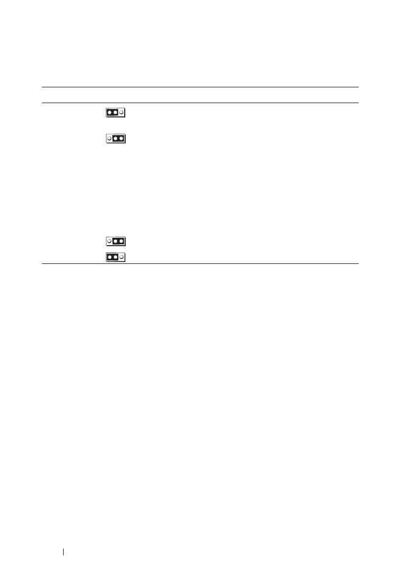
Tabelle 1-2. Einstellungen der Jumper auf der Systemplatine
Jumper Einstellung Beschreibung
NVRAM_CLR (Standardeinstellung) Die Konfigurationseinstellungen
bleiben beim Systemstart erhalten.
Die Konfigurationseinstellungen
werden beim nächsten Systemstart
gelöscht. (Sollten die Konfigurations-
einstellungen beschädigt worden sein,
sodass das System nicht starten kann,
installieren Sie den Jumper und starten
Sie das System neu. Entfernen Sie den
Jumper wieder, bevor Sie die Konfigu-
rationsdaten wiederherstellen.)
PWRD_EN (Standardeinstellung) Die Kennwortfunktion ist aktiviert.
Die Kennwortfunktion ist deaktiviert.
Informationsaktualisierung 69
Update zum Systemspeicher
Die auf dem System unterstützten 8-GB-DIMM-Module sind 533-MHz-
Vierfachmodule. Alle anderen Größen unterstützter DIMM-Module (512 MB,
1 GB, 2 GB und 4 GB) sind 667-MHz-Module. Beim Systembetrieb mit
gemischtem Einsatz von 533-MHz- und 667-MHz-DIMM-Modulen werden alle
DIMM-Module auf die niedrigere 533-MHz-Signalrate heruntergestuft. Daher
werden gemischte Speicherkonfigurationen mit 8-GB-DIMM-Modulen auf dem
System nicht unterstützt; dies führt beim Systemstart zu einer Fehlermeldung
dahingehend, dass die Speicherkonfiguration nicht-optimal ist. Tabelle 1-3 und
Tabelle 1-4 enthalten Updates zum
Hardware-Benutzerhandbuch
hinsichtlich
der derzeit unterstützten Speicher- und Speicherredundanzkonfigurationen für
das System.
Tabelle 1-3. Speicherkonfigurationen
Gesamtsystemspeicher CPU 1 DIMM-Paare
(Kapazität pro DIMM)
CPU 2 DIMM-Paare
(Kapazität pro DIMM)
1 CPU 2 Prozessoren DIMM 1/2 DIMM 3/4 DIMM 5/6 DIMM 7/8
1 GB 2 GB 512 MB 512 MB
2 GB 4 GB 512 MB 512 MB 512 MB 512 MB
2 GB 4 GB 1 GB 1 GB
3 GB 6 GB 1 GB 512 MB 1 GB 512 MB
4 GB 8 GB 1 GB 1 GB 1 GB 1 GB
4 GB 8 GB 2 GB 2 GB
5 GB 10 GB 2 GB 512 MB 2 GB 512 MB
6 GB 12 GB 2 GB 1 GB 2 GB 1 GB
8 GB 16 GB 2 GB 2 GB 2 GB 2 GB
8 GB 16 GB 4 GB 4 GB
9 GB 18 GB 4 GB 512 MB 4 GB 512 MB
10 GB 20 GB 4 GB 1 GB 1 GB 4 GB
12 GB 24 GB 4 GB 2 GB 2 GB 4 GB
16 GB 32 GB 4 GB 4 GB 4 GB 4 GB
16 GB 32 GB 8 GB 8 GB
32 GB 64 GB 8 GB 8 GB 8 GB 8 GB
70 Informationsaktualisierung
Die auf dem System unterstützten 8-GB-DIMM-Module sind Vierfachmodule.
Bei Verwendung von Vierfach-DIMM-Modulen in einer Speicherredundanzkon-
figuration ergibt sich ein proportional kleinerer Anteil von redundantem
Speicher als beim Einsatz von Einfach- oder Zweifachmodulen in einer
ähnlichen Konfiguration. Da redundanter Speicher nach DIMM-Rängen
zugewiesen wird, wird ein Viertel eines Vierfach-DIMM-Moduls verwendet
(ein Rang von vieren) statt der Hälfte bei einem Zweifachmodul oder der
vollen Kapazität eines Einfachmoduls. Tabelle 1-4 ersetzt die Informationen
im
Hardware-Benutzerhandbuch
hinsichtlich der auf dem System unterstützten
Speicherredundanzkonfigurationen.
Tabelle 1-4. Speicherredundanz bei Ein- und Zweiprozessor-Konfigurationen
Prozessor 1 Prozessor 2 Verfügbarer
Speicher
Redundanter
Speicher
DIMM
Paar 1/2
DIMM
Paar 3/4
DIMM
Paar 5/6
DIMM
Paar 7/8 1 CPU / 2 CPUs 1 CPU / 2 CPUs
512 MB
512 MB
512 MB
512 MB
1 GB / 2 GB 1 GB / 2 GB
1 GB
512 MB
1 GB
512 MB 1 GB / 2 GB 2 GB / 4 GB
1 GB
1 GB
1 GB
1 GB
2 GB / 4 GB 2 GB / 4 GB
2 GB
512 MB
2 GB
512 MB 3 GB / 6 GB 2 GB / 4 GB
2 GB
1 GB
2 GB
1 GB
4 GB / 8 GB 2 GB / 4 GB
2 GB
2 GB
2 GB
2 GB
6 GB / 12 GB 2 GB / 4 GB
4 GB
512 MB
4 GB
512 MB 5 GB / 10 GB 4 GB / 8 GB
4 GB
1 GB
4 GB
1 GB 6 GB / 12 GB 4 GB / 8 GB
4 GB
2 GB
4 GB
2 GB 8 GB / 16 GB 4 GB / 8 GB
4 GB
4 GB
4 GB
4 GB
12 GB / 24 GB 4 GB / 8 GB
8 GB
8 GB
8 GB
8 GB
28 GB / 56 GB 4 GB / 8 GB
Ersatzspeicher aus Einzel-DIMM (512 MB oder 1 GB). Die gesamte Kapazität
dieses DIMM-Moduls ist für Speicherredundanz reserviert.
Zeigt ein redundantes Zweifach-DIMM-Modul an (2 GB oder 4 GB). Die Hälfte
der Kapazität dieses DIMM-Moduls wird als Ersatzspeicher reserviert.
8-GB-DIMM-Module sind Vierfachmodule. Ein Viertel der Kapazität
dieses DIMM-Moduls ist für Speicherredundanz reserviert.
Informationsaktualisierung 71
Update zum 3,5-Zoll-Gehäuse
Funktionsmerkmale und Anzeigen auf der Vorderseite
Abbildung 1-2 und Tabelle 1-5 zeigen die Steuerelemente, Anzeigen und
Anschlüsse, die sich hinter der optionalen Rackblende auf der Vorderseite
des Systems befinden.
Abbildung 1-2. Merkmale und Anzeigen auf der Vorderseite
6
5
4
3
2
1
87
72 Informationsaktualisierung
Tabelle 1-5. LED-Anzeigen, Tasten und Anschlüsse auf der Vorderseite
Bauteil Anzeige, Taste
oder Anschluss
Symbol Beschreibung
1
Betriebsanzeige,
Netzschalter
Die Betriebsanzeige leuchtet,
wenn das System eingeschaltet ist.
Über den Netzschalter wird die
Gleichstromversorgung des Systems
gesteuert.
ANMERKUNG: Wenn Sie das System
über den Betriebsschalter ausschalten
und ein ACPI-konformes Betriebssystem
ausgeführt wird, kann das System
ordnungsgemäß herunterfahren, bevor
die Stromzufuhr unterbrochen wird.
Wenn auf dem System kein ACPI-
konformes Betriebssystem ausgeführt
wird, wird die Stromversorgung sofort
nach dem Drücken des Betriebs-
schalters unterbrochen.
2
NMI-Taste Dient dazu, Softwareprobleme und
Fehler von Gerätetreibern zu beheben,
wenn bestimmte Betriebssysteme
verwendet werden. Sie können diese
Taste mit einer aufgebogenen
Büroklammer betätigen.
Diese Taste sollte nur auf Anweisung
eines zugelassenen Support-Mitarbeiters
oder entsprechend der Dokumentation
des Betriebssystems verwendet werden.
3
System-
identifikationstaste
Die Identifikationstasten auf der Vorder-
und Rückseite dienen dazu, ein
bestimmtes System innerhalb eines
Racks zu lokalisieren. Wird eine dieser
Tasten gedrückt, blinken die LCD-
Anzeige auf der Vorderseite und die
blaue Systemstatusanzeige auf der
Rückseite, bis eine der Tasten erneut
gedrückt wird.
Informationsaktualisierung 73
4
LCD-Anzeige Zeigt System-ID, Statusinformationen
und Systemfehlermeldungen an.
Das LCD-Display leuchtet während des
normalen Systembetriebs. Sowohl die
Systemverwaltungssoftware als auch die
Identifikationstasten auf der Vorder- und
Rückseite des Systems können bewirken,
dass die LCD-Anzeige blau blinkt, um
ein bestimmtes System zu identifizieren.
Das LCD-Display leuchtet gelb, wenn
das System überprüft werden muss.
Gleichzeitig wird ein entsprechender
Fehlercode mit Beschreibung angezeigt.
ANMERKUNG: Wenn das System an
den Netzstrom angeschlossen ist und ein
Fehler festgestellt wurde, blinkt das LCD-
Display gelb, unabhängig davon, ob das
System eingeschaltet ist oder nicht.
5
USB-Anschlüsse
(2)
Zum Anschließen USB-2.0-konformer
Geräte am System.
6
Bildschirm-
anschluss
Zum Anschließen eines Bildschirms
an das System.
7
Festplatten-
laufwerke (6)
Bis zu sechs hot-plug-fähige 3,5-Zoll-
Festplatten
8
Optisches Laufwerk
(optional)
Ein optionales DVD-Laufwerk
in Flachbauweise
Tabelle 1-5. LED-Anzeigen, Tasten und Anschlüsse auf der Vorderseite (fortgesetzt)
Bauteil Anzeige, Taste
oder Anschluss
Symbol Beschreibung
74 Informationsaktualisierung
Gemischte SAS/SATA-Festplattenkonfiguration (nur 3,5-Zoll-Laufwerke)
Beim 3,5-Zoll-Gehäuse lassen sich in den Festplattenschächten zwei SATA-
Laufwerke mit einem bis vier SAS-Laufwerken gemischt einsetzen. Die SAS/
SATA-Konfiguration erfordert zwei SATA-Laufwerke, die in den Festplatten-
schächten 0 und 1 installiert werden müssen. In den verbleibenden Festplatten-
schächten (2 bis 5) können nur SAS-Laufwerke oder Platzhalter installiert
werden.
Entfernen eines 3,5-Zoll-Laufwerkplatzhalters
VORSICHTSHINWEIS: Um eine ausreichende Systemkühlung zu gewährleisten,
müssen alle leeren Festplattenschächte mit entsprechenden Platzhaltern belegt
sein. Wenn Sie einen Festplattenträger aus dem System entfernen und nicht
wieder installieren, müssen Sie den Laufwerksträger durch einen Platzhalter
ersetzen.
1
Entfernen Sie gegebenenfalls die Frontverkleidung. Siehe „Entfernen
der Frontverkleidung“ im
Hardware-Benutzerhandbuch
.
2
Führen Sie einen Finger unter das versenkte Ende des Platzhalters
und drücken Sie die Sperrklinke nach innen, um den Platzhalter
aus dem Schacht zu lösen.
3
Ziehen Sie die Enden des Platzhalters nach außen, bis der Schacht frei ist.
Installieren eines 3,5-Zoll-Laufwerkplatzhalters
Der Laufwerksplatzhalter ist kodiert, um ein verkehrtes Einbauen im Schacht
zu vermeiden. Um einen 3,5-Zoll-Laufwerkplatzhalter zu installieren, setzen Sie
ihn mit der passgeformten Seite voran im Laufwerkschacht ein, und drücken Sie
gleichmäßig auf das andere Ende des Platzhalters, bis er vollständig eingesetzt
und verriegelt ist.
Informationsaktualisierung 75
Entfernen der SAS/SATA-Rückwandplatine
WARNUNG: Nur ausgebildete Service-Techniker dürfen die Gehäuseabdeckung
entfernen und auf die Komponenten im Inneren des Systems zugreifen.
Ausführliche Informationen zu den Sicherheitsvorkehrungen beim Arbeiten
im Innern des Computers und zum Schutz vor elektrischer Entladung finden Sie
im Produktinformationshandbuch.
1
Schalten Sie das System und die angeschlossenen Peripheriegeräte aus
und trennen Sie das System vom Netzstrom.
2
Öffnen Sie das System. Siehe „Öffnen des Systems“ im
Hardware-
Benutzerhandbuch
.
3
Öffnen Sie den Freigabegriff an jedem Festplattenlaufwerk und ziehen Sie
alle Laufwerke teilweise aus den Schächten. Siehe Abbildung 1-3.
ANMERKUNG: Wenn Sie die Laufwerke entfernen, müssen Sie sich die
jeweiligen Schachtpositionen notieren. Siehe „Entfernen einer Hot-Plug-
Festplatte“ im Hardware-Benutzerhandbuch.
Abbildung 1-3. SAS/SATA-Rückwandplatine entfernen
1 Laufwerkträger 2 SAS-Rückwandplatine
3 SAS-Rückwandplatine Freigabestift
3
1
2
76 Informationsaktualisierung
4
Trennen Sie gegebenenfalls das Stromversorgungskabel des optischen
Laufwerks von der SAS/SATA-Rückwandplatine. Die Position des
Stromversorgungsanschlusses des optsichen Laufwerks können Sie
Abbildung 1-4 entnehmen.
5
Trennen Sie die SAS-Kabel von den Anschlüssen auf der Rückwandplatine.
Die Position der SATA-Kabelanschlüsse ist Abbildung 1-4 zu entnehmen.
6
Wenn ein optisches Laufwerk installiert ist, trennen Sie das Datenkabel
von der Rückseite des optischen Laufwerks.
7
Entfernen Sie gegebenenfalls die Speichercontrollerzusatzkarte.
Siehe „Entfernen einer SAS-Controllerzusatzkarte“ im
Hardware-
Benutzerhandbuch
.
8
Entfernen Sie die SAS-Rückwandplatine:
a
Ziehen Sie den Freigabestift der SAS-Rückwandplatine.
Siehe Abbildung 1-3.
b
Schwenken Sie die Rückwandplatine bei gezogenem Freigabestift
zur Systemrückseite.
c
Heben Sie die Rückwandplatine aus den Sicherungslaschen, und
ziehen Sie sie aus dem Gehäuse heraus.
Informationsaktualisierung 77
Installieren der SAS-Rückwandplatine
WARNUNG: Nur ausgebildete Service-Techniker dürfen die Gehäuseabdeckung
entfernen und auf die Komponenten im Inneren des Systems zugreifen.
Ausführliche Informationen zu den Sicherheitsvorkehrungen beim Arbeiten im
Innern des Computers und zum Schutz vor elektrischer Entladung finden Sie im
Produktinformationshandbuch.
1
Positionieren Sie die SAS-Rückwandplatine so, dass die Sicherungslaschen
des Laufwerksträgers vollständig in die Sicherungsschlitze der Rückwand-
platine einrasten. Siehe Abbildung 1-3.
2
Ziehen Sie den Freigabestift der SAS-Rückwandplatine.
Siehe Abbildung 1-3.
3
Schwenken Sie die SAS-Rückwandplatine bei gezogenem Freigabestift bis
zum Anschlag in Richtung zur Systemvorderseite. Lassen Sie den
Freigabestift anschließend los und vergewissern Sie sich, dass er einrastet.
4
Installieren Sie die SAS-Controllerzusatzkarte. Siehe „Installieren einer
SAS-Controllerzusatzkarte“ im
Hardware-Benutzerhandbuch
.
5
Schließen Sie die Kabel der SAS-Controllerzusatzkarte und des Bedien-
felds wieder an.
6
Setzen Sie die Festplatten wieder ein.
7
Verbinden Sie gegebenenfalls das Stromversorgungskabel des optischen
Laufwerks mit der Rückwandplatine. Siehe „Installieren des optischen
Laufwerks“ im
Hardware-Benutzerhandbuch
.
8
Schließen Sie das System. Siehe „Schließen des Systems“ im
Hardware-
Benutzerhandbuch
.
78 Informationsaktualisierung
Anschlüsse der SAS/SATA-Rückwandplatine
Abbildung 1-4 zeigt die Position der Anschlüsse auf der SAS/SATA-Rückwand-
platine.
Abbildung 1-4. Komponenten der SAS-Rückwandplatine: x4-Option (3,5 Zoll)
1 Primärer SAS-Anschluss
(SAS_A)
2 Stromversorgung für
optisches Laufwerk (CD_PWR)
3 Sekundärer SAS-Anschluss
(SAS_B)
4 Laufwerk 5 (SASDRV5)
5 Rückwandplatinen-
Stromanschluss (BP_PWR)
6 Laufwerk 4 (SASDRV4)
7 Laufwerk 3 (SASDRV3) 8 Laufwerk 2 (SASDRV2)
9 Laufwerk 1 (SASDRV1) 10 Laufwerk 0 (SASDRV0)
9
8
7
6
1
Vorderseite
Rückseite
2
3
10
5
4
Dell™ PowerEdge™ 2970
アップデート情報
メモ、注意、警告
メモ: コンピュータを使いやすくするための重要な情報を説明
しています。
注意 : 手順に従わない場合は、ハードウェアの損傷やデータの
損失の可能性があることを示しています。
警告: 物的損害、けが、または死亡の原因となる可能性があ
ることを示しています。
____________________
本書の内容は予告なく変更されることがあります。
© 2007-2009
すべての著作権は
Dell Inc.
にあります。
Dell Inc.
の書面による許可のない複製は、いかなる形態においても厳重に禁じられています。
本書に使用されている商標
Dell
DELL
ロゴ、
OpenManage
および
PowerEdge
Dell
Inc.
の商標です。
Microsoft
および
Windows
は米国その他の国における
Microsoft Corporation
の登録商標です。
Red Hat
および
Red Hat Enterprise Linux
Red Hat, Inc.
の登録商標です。
SUSE
Novell Inc.
の登録商標です。
AMD PowerNow!
Advanced Micro Devices, Inc.
の商標です。
商標または製品の権利を主張する事業体を表すためにその他の商標および社名が使用されてい
ることがあります。それらの商標や会社名は、一切
Dell Inc.
に帰属するものではありません。
2009 11 Rev. A06
目次 81
目次
最適でないメモリ構成 . . . . . . . . . . . . . . . . 83
ウェブサイトで入手可能な各国語の
『ハードウェアオーナーズマニュアル』
. . . . . . . 83
オンライン診断プログラムの使い方
. . . . . . . . 83
セットアップユーティリティに関するア
ップデート情報
. . . . . . . . . . . . . . . . . . . . 84
メモリ最適化テクノロジ
. . . . . . . . . . . . 84
QDMA モード機能
. . . . . . . . . . . . . . . . . 84
Demand-Based Power Management
(デマンドベースの電力管理)機能
. . . . . . 84
追加の CPU 情報
. . . . . . . . . . . . . . . . . . 85
デフォルト設定のアップデート
. . . . . . . . 85
システム起動時の動作
. . . . . . . . . . . . . . . . 85
USB ポートの過電流イベント
. . . . . . . . . . . . 86
LCD ステータスメッセージのアップデート
. . . . 86
システム基板のジャンパ
. . . . . . . . . . . . . . . 87
BMC ユーザーパスワードの設定
. . . . . . . . . . . 88
システムメモリのアップデート
. . . . . . . . . . . 89
82 目次
3.5 インチシャーシのアップデート . . . . . . . . . 91
前面パネルの機能およびインジケータ
. . . . 91
SAS/SATA ハードドライブが混在する構成
3.5 インチドライブのみ)
. . . . . . . . . . . . 93
3.5 インチドライブダミーの取り外し
. . . . . 93
3.5 インチドライブダミーの取り付け
. . . . . 94
SAS/SATA バックプレーンボード
の取り外し
. . . . . . . . . . . . . . . . . . . . . 94
SAS バックプレーンボードの取り付け
. . . . 96
SAS/SATA バックプレーンボード
コネクタ
. . . . . . . . . . . . . . . . . . . . . . 97
アップデート情報 83
最適でないメモリ構成
『ハードウェアオーナーズマニュアル』の表
3-1
と表
3-2
のどちらにも記載
されていないメモリ構成は、最適でない構成です。メモリ構成が最適でな
いことが検知されると
POST
が中断され、次のメッセージが表示されます。
Non-Optimal Memory Configuration
(メモリ構成が最適ではありません)
Press F1 to continue or F2 for Setup
(続行するには
F1
を、セットアップに進むには
F2
を押します)
メモ: 速度の異なる DIMM を混在させると、メモリ構成が最適でなくな
ります。システムは、チャネルの DIMM セット内の最も遅い DIMM に合わ
せてパフォーマンスをクロックダウンします。
ウェブサイトで入手可能な各国語の
『ハードウェアオーナーズマニュアル』
製造段階では『ハードウェアオーナーズマニュアル』の各国語翻訳版を
Dell
OpenManage™
Documentation CD
(バージョン
5.2
)に収録で
きませんでした。通常
CD
に収録されている『ハードウェアオーナーズマ
ニュアル』のすべてのバージョンは、デルサポートサイト
support.dell.com
からダウンロードできます。
オンライン診断プログラムの使い方
『ハードウェアオーナーズマニュアル』の「
Server
Administration
診断プ
ログラムの使い方」で言及されているオンラインの
Server Administrator
診断ツールは新しくなり、
Dell PowerEdge™ Diagnostics
シリーズのオ
ンライン診断プログラムに切り替わっています。
Dell PowerEdge
Diagnostics
には、ハードドライブ、物理メモリ、通信ポート、
NIC
CMOS
など、シャーシやストレージコンポーネントを対象とするオンラ
イン診断テストが含まれています。
システムの問題を分析するには、オンラインの
Dell PowerEdge
Diagnostics
を最初に使用します。
Dell PowerEdge Diagnostics
を使用し
て問題を識別できない場合は、システム診断プログラムを使用します。
84 アップデート情報
サポートされている
Microsoft
®
Windows
®
OS
および
Linux OS
を実行し
ているシステムで
PowerEdge Diagnostics
を実行するために必要なファ
イルは、システムに付属の
CD
に収録されています。または、
support.dell.com
から入手することもできます。診断プログラムの使
い方の詳細については、
Dell PowerEdge Diagnostics
の『ユーザーズガ
イド』を参照してください
セットアップユーティリティに関するアップ
デート情報
メモリ最適化テクノロジ
最新の
BIOS
アップデートでは、セットアップユーティリティの
Memory Information
(メモリ情報)画面にメモリを最適化する機能が
備わっています。
Memory Optimizer Technology
(メモリ最適化テク
ノロジ)オプションを使用すると、
2
個の
DRAM
コントローラがパラレ
64
ビットモードで独立して機能するように設定したり(このモードで
はアドバンスト
ECC
は使用できません)、この機能を無効にして、アドバ
ンスト
ECC
を使用してデフォルトの
128
ビットモードでコントローラを
実行したりできます。
QDMA モード機能
Integrated Devices
(内蔵デバイス)画面で、
Embedded SATA
(内
SATA
)フィールドに
QDMA Mode
QDMA
モード)オプションが利
用できるようになりました。
QDMA Mode
QDMA
モード)に設定する
と、内蔵
SATA
コントローラは
ATA Mode
ATA
モード)でサポートさ
れている
PIO
レートよりも速いデータ転送速度で
ATAPI
デバイスを使用
できます。
QDMA Mode
QDMA
モード)を使用するには、
OS
にデバ
イスドライバをインストールする必要があります。
Demand-Based Power Management(デマンドベースの電力管理)
機能
セットアップユーティリティの
CPU Information
CPU
情報)画面にあ
Demand-Based Power Management
(デマンドベースの電力管
理)オプションは、バージョン
5
よりも古い
Red Hat
®
Enterprise Linux
®
OS
ではサポートされていません。このオプションは、
CPU
AMD
PowerNow!™
テクノロジの機能を有効にするものです。
アップデート情報 85
SUSE
®
Linux Enterprise Server 10
はデマンドベースの電力管理を完全に
サポートしています。
SUSE Linux Enterprise Server 9
は、デュアルコア
AMD
プロセッサが使用されている場合はデマンドベースの電力管理をサ
ポートしますが、新しいクアッドコアプロセッサ使用の場合はサポートし
ません。
追加の CPU 情報
CPU Information
CPU
情報)画面のプロセッサフィールドに、表示さ
れているプロセッサのシリーズ、モデル、ステッピングが示されるように
なりました。
デフォルト設定のアップデート
次の
2
点は、『ハードウェアオーナーズマニュアル』に記載されている情
報に対するアップデートです。
Serial Communication
(シリアル通信)画面で、
Serial
Communication
(シリアル通信)フィールドのデフォルト設定は
On without Console Redirection
(コンソールリダイレクション
なしでオン)です。
Serial Communication
(シリアル通信)画面で、
Failsafe Baud
Rate
(フェイルセーフボーレート)フィールドのデフォルト設定は
115200
です。
システム起動時の動作
システム起動時に次のイベントが発生する場合があります。
容量の大きいメモリ構成のシステムでは、ビデオモニターが起動時
に画像を表示するのに数秒から約
2
分かかる場合があります。
Red Hat Enterprise Linux WS
ES
、または
AS
(バージョン
4
x86-64
)を使用している場合、システム起動時に次のメッセージが
画面に数回表示されることがあります。
clear kernel mapping: mapping is split:
will leak memory
このメッセージは
OS
固有のものであり、お使いのシステムのハード
ウェアに問題があることを示すものではありません。
86 アップデート情報
USB ポートの過電流イベント
USB
デバイスによっては、システムの
USB
ポートに過電流が発生する場
合があります。過電流が発生すると、影響のある
USB
ポートの
1
つまた
は複数が無効になり、接続されている
USB
デバイスとの通信が中断され
ます。このイベントを通知するシステムメッセージが画面に表示される場
合もありますが、(背面
USB
ポートに接続されているデバイスの場合は特
に)メッセージが表示されるとは限りません。過電流によってシステムの
USB
ポートが無効になった場合は、システムを再起動することでポート
を有効な状態に戻してください。
過電流イベントが繰り返し発生する場合、システムに接続されている
USB
デバイスの取り外しまたは交換が必要な場合があります。
LCD ステータスメッセージのアップデート
LCD
ステータスメッセージとその考えられる原因のアップデート情報を
1-1
に示します。
LCD
メッセージは、システムイベントログ(
SEL
)に
記録されたイベントに基づきます。
SEL
およびシステム管理設定の詳細に
ついては、システム管理ソフトウェアのマニュアルを参照してください。
1-1. LCD ステータスメッセージ
コード メッセージ 原因 対応処置
E1232 VDD 12V
PS# PwrGd
システムの電源がオン
になっていたときに、
表示されている電源ユ
ニットの AC 電源が切
れました。AC 電源が
切れていなかった場合
は、表示されている電
源ユニットに障害が発
生しています。
AC 電源が切れていた場合は、
このメッセージは情報の表示の
みです。電源ユニットに障害が
発生した場合は、『ハードウェ
アオーナーズマニュアル』の
「困ったときは」を参照してく
ださい。
E141C CPU
Mismatch
システム内の CPU
組み合わせはサポート
されていません。
CPU を一致するペアに取り替
えるか、またはその他の有効な
CPU 構成にしてください。
アップデート情報 87
システム基板のジャンパ
お使いのシステムの『ハードウェアオーナーズマニュアル』の図
6-1
に示
され、表
6-1
で説明されているジャンパの設定は正しくありません。
正しい設定は
1-1
に示され、表
1-2
で説明されています。
1-1. システム基板のジャンパ
88 アップデート情報
BMC ユーザーパスワードの設定
BMC
管理ユーティリティを使用してお使いのシステムのベースボード管
理コントローラ(
BMC
)に接続するには、事前に有効な
LAN
ユーザー名
とパスワードを設定する必要があります。
LAN
ユーザー名とパスワード
を設定するには、次の
2
つの方法があります。
システム起動中に
<CTRL>+<E>
を押して
BMC
リモートアクセス
ユーティリティにアクセスすると、
LAN
ユーザー名と最大
16
文字
までのパスワードを設定できます
(このユーティリティを使用して
設定できる
LAN
ユーザー名および関するパスワードは
1
す)。このオプションの詳細については、
Dell
OpenManage
ベース
ボード管理コントローラユーティリティの『ユーザーズガイド』で、
「ベースボード管理コントローラの設定」を参照してください。
Deployment Toolkit SYSCFG.EXE
ユーティリティを使用する場合は、
syscfg passwordaction
コマンドを使用して、
LAN
ユーザー名
と最大
20
文字までのパスワードを設定できます。詳細については、
BMC
の『ユーザーズガイド』で「
Configuring New BMC Users
(新しい
BMC
ユーザーの設定)を参照してください。
1-2. システム基板のジャンパ設定
ジャンパ 設定 説明
NVRAM_CLR
(デフォルト) 設定がシステム起動時に保持されます。
設定が次回のシステム起動時にクリア
されます。(設定が壊れてシステムが起
動しない場合は、ジャンパを取り付け
てシステムを起動します。ジャンパプ
ラグを取り外してから設定情報を復元
してください)
PWRD_EN
(デフォルト) パスワード機能は有効です。
パスワード機能は無効です。
アップデート情報 89
システムメモリのアップデート
お使いのシステムでサポートされている
8 GB DIMM
は、
533 MHz
アッドランクモジュールです。サポートされているその
DIMM
のサ
イズ(
512 MB
1 GB
2 GB
、および
4 GB
)のメモリモジュールは、す
べて
667 MHz
です。
533 MHz
667 MHz
DIMM
混在するシステム
では、すべての
DIMM
い方の
533 MHz
で動します。したがって、
お使いのシステムでは種類なる
8 GB
DIMM
を使用する構成はサ
ポートされておら、起動時にメモリ構成が最適でないことを示すラー
メッセージが表示されます。現在サポートされているシステムメモリ構成
とメモリスアリング構成に関する『ハードウェアオーナーズマニュア
ル』のアップデート情報を
1-3
1-4
に示します。
1-3. メモリ構成
システムメモリの総量 CPU 1 DIMM のペア
DIMM 1 枚のサイズ)
CPU 2 DIMM のペア
DIMM 1 枚のサイズ)
CPU 1 CPU 2
DIMM 1/2 DIMM 3/4 DIMM 5/6 DIMM7/8
1 GB 2 GB 512 MB 512 MB
2 GB 4 GB 512 MB 512 MB 512 MB 512 MB
2 GB 4 GB 1 GB 1 GB
3 GB 6 GB 1 GB 512 MB 1 GB 512 MB
4 GB 8 GB 1 GB 1 GB 1 GB 1 GB
4 GB 8 GB 2 GB 2 GB
5 GB 10 GB 2 GB 512 MB 2 GB 512 MB
6 GB 12 GB 2 GB 1 GB 2 GB 1 GB
8 GB 16 GB 2 GB 2 GB 2 GB 2 GB
8 GB 16 GB 4 GB 4 GB
9 GB 18 GB 4 GB 512 MB 4 GB 512 MB
10 GB 20 GB 4 GB 1 GB 1 GB 4 GB
12 GB 24 GB 4 GB 2 GB 2 GB 4 GB
16 GB 32 GB 4 GB 4 GB 4 GB 4 GB
16 GB 32 GB 8 GB 8 GB
32 GB 64 GB 8 GB 8 GB 8 GB 8 GB
90 アップデート情報
お使いのシステムでサポートされている
8 GB DIMM
は、クアッドランク
モジュールです。メモリスアリング構成でクアッドランク
DIMM
を使
用すると、同様の構成でシングルまたはデュアルランクの
DIMM
を使用
した場合とべて、スアメモリの容量がなくなります。メモ
リスアリングでは、
DIMM
ランクとにスアメモリをてるた
め、デュアルランク
DIMM
では
1/2
、シングルランク
DIMM
では全容量
てられるのに対して、クアッドランク
DIMM
では
1/4
= 4
つラ
ンクのう
1
つ)のがスアにてられます。お使いのシステ
ムでサポートされているメモリスアリング構成に関する『ハードウェア
オーナーズマニュアル』のアップデート情報を
1-4
に示します。
1-4. シングルおよびデュアルプロセッサ構成におけるメモリスペアリング
プロセッサ 1 プロセッサ 2 使用可能
メモリ
スペアメ
モリ
DIMM
ペア 1/2
DIMM
ペア 3/4
DIMM
ペア 5/6
DIMM
ペア 7/8
CPU 1 /
CPU 2
CPU 1 /
CPU 2
512 MB
512 MB 512 MB 512 MB 1 GB / 2 GB 1 GB / 2 GB
1 GB 512 MB 1 GB 512 MB 1 GB / 2 GB 2 GB / 4 GB
1 GB
1 GB 1 GB 1 GB 2 GB / 4 GB 2 GB / 4 GB
2 GB 512 MB 2 GB 512 MB 3 GB / 6 GB 2 GB / 4 GB
2 GB
1 GB 2 GB 1 GB 4 GB / 8 GB 2 GB / 4 GB
2 GB
2 GB 2 GB 2 GB 6 GB / 12 GB 2 GB / 4 GB
4 GB 512 MB 4 GB 512 MB 5 GB / 10 GB 4 GB / 8 GB
4 GB 1 GB 4 GB 1 GB 6 GB / 12 GB 4 GB / 8 GB
4 GB 2 GB 4 GB 2 GB 8 GB / 16 GB 4 GB / 8 GB
4 GB
4 GB 4 GB 4 GB 12 GB / 24 GB 4 GB / 8 GB
8 GB 8 GB 8 GB 8 GB 28 GB / 56GB 4 GB / 8 GB
はスペアのシングルランク DIMM512 MB または 1 GB)を示します。
この DIMM の全容量がスペアリング用に予約されます。
はスペアのデュアルランク DIMM2 GB または 4 GB)を示します。
この DIMM の容量の 1/2 がスペアリング用に予約されます。
8 GB DIMM はクアッドランクです。この DIMM の容量の 1/4 がス
ペアリング用に予約されます。
アップデート情報 91
3.5 インチシャーシのアップデート
前面パネルの機能およびインジケータ
システム前面パネルのオプションのラックベルの背面にあるボタン、
インジータ、およびコネクタを
1-2
および
1-5
に示します。
1-2. 前面パネルの機能およびインジケータ
1-5. 前面パネルの LED インジケータ、ボタン、およびコネクタ
項目 インジケータ、
ボタン、 また
はコネクタ
アイコン 説明
1
電源インジケ
ータ、電源
ボタン
電源オンインジケータは、システムの
電源が入っている場合に点灯します。
電源ボタンによってシステムへの直流
電源の供給を制御します。
メモ: ACPI 対応の OS を実行している
場合、電源ボタンを使ってシステムの
電源を切れば、システムは電源が切れ
る前に正常なシャットダウンを実行で
きます。システムが ACPI 対応の OS
実行していない場合、電源ボタンを押
すと電源がただちに切れます。
6
5
4
3
2
1
87
92 アップデート情報
2
NMI ボタン 特定の OS を使用している際に、ソフ
トウェアエラーおよびデバイスドライ
バエラーのトラブルシューティングを
行います。このボタンは、ペーパーク
リップの先端を使って押すことができ
ます。
認定を受けたサポート担当者によって
指示された場合、または OS のマニュ
アルで指示されている場合にのみ、
このボタンを使用してください。
3
システム識別ボ
タン
前面パネルと背面パネルの識別ボタン
は、ラック内の特定のシステムの位置
を確認するために使用します。これら
のボタンの 1 つを押すと、前面の LCD
パネルと背面の青色のシステムステー
タスインジケータは、ボタンの 1 つを
もう一度押すまで点滅を続けます。
4
LCD パネル システム ID、ステータス情報、システ
ムエラーメッセージが表示されます。
LCD は通常のシステム動作中に点灯し
ます。特定のシステムを識別するに
は、システム管理ソフトウェアとシス
テムの前面および背面にある識別ボタ
ンのどちらも使うことができます。青
色の LCD の点滅で、どのシステムか
が識別できます。
システムに注意が必要な状況になると
LCD が黄色に点灯し、LCD パネルには
エラーコードとエラーの内容を説明す
るテキストが表示されます。
メモ: システムが AC 電源に接続され
ている状態でエラーが検出されると、
LCD はシステムの電源がオンになって
いてもいなくても黄色に点灯します。
1-5. 前面パネルの LED インジケータ、ボタン、およびコネクタ (続き)
項目 インジケータ、
ボタン、 また
はコネクタ
アイコン 説明
アップデート情報 93
SAS/SATA ハードドライブが混在する構成
3.5 インチドライブのみ)
3.5
インのシャーシでは、
SAS
ハードドライブ
1
4
を使用して、
ハードドライブベイに
2
SATA
ハードドライブを混在させることが
能です。
SAS/SATA
の構成では、
2
SATA
ドライブをドライブベイ
0
1
に取り付る必要があります。りのドライブベイ(
2
5
)には必
SAS
ハードドライブまたはドライブダーを取り付てください。
3.5 インチドライブダミーの取り外し
注意 : システムの正常な冷却状態を維持するために、空のハードドライブ
ベイすべてにドライブのダミーを取り付ける必要があります。システムか
らハードドライブキャリアを取り外し、再度取り付けない場合は、キャリ
アにドライブのダミーを装着して取り付けなおす必要があります。
1
前面ベルが取り付てある場合は、これを取り外します。
『ハードウェアオーナーズマニュアル』の「前面ベルの取り外し」
を参照してください。
2
ーのバーがあるを入れてラッを押し、
ーをベイから取りします。
3
ーが外れるまで、ダーの両端きます。
5
USB コネクタ
2
USB 2.0 対応デバイスをシステムに接
続するときに使用します。
6
ビデオコネクタ モニターをシステムに接続します。
7
ハードドライブ
6
3.5 インチホットプラグ対応ハードド
ライブが最大 6
8
オプティカルド
ライブ(オプ
ション)
オプションのスリムライン DVD ドラ
イブ 1
1-5. 前面パネルの LED インジケータ、ボタン、およびコネクタ (続き)
項目 インジケータ、
ボタン、 また
はコネクタ
アイコン 説明
94 アップデート情報
3.5 インチドライブダミーの取り付け
ドライブのダーは、正しいきでないとドライブベイに入できないよ
うになっています。
3.5
インドライブのダーを取り付るには、
ーのーのあるをドライブベイに入し、完全に押しまれてラッ
がかかるまで、ダーのもう方の均等の力で押します。
SAS/SATA バックプレーンボードの取り外し
警告: システムのカバーを取り外して内部の部品に手を触れる作業は、
トレーニングを受けたサービス技術者のみが行ってください。安全上の
注意、コンピュータ内部の作業、および静電気障害への対処の詳細につい
ては、『製品情報ガイド』を参照してください。
1
システムおよび接続されている周辺の電を切って、システム
を電コンセントから外します。
2
システムバーをきます。『ハードウェアオーナーズマニュアル』
の「システムバーの取り外し」を参照してください
3
各ハードドライブのドライブャリアリリースハンドルをき、
すべてのハードドライブをベイからします。
1-3
を参照してください。
メモ: ハードドライブを取り外す場合は、どのハードドライブをど
のベイから取り外したかを必ず記録しておいてください。『ハード
ウェアオーナーズマニュアル』の「ホットプラグ対応ハードドライ
ブの取り外し」を参照してください。
アップデート情報 95
1-3. SAS/SATA バックプレーンボードの取り外し
4
SAS/SATA
バックプレーンボードにオプティルドライブの電源ケ
ブルが接続されている場合は、ーブルを外します。オプティ
ドライブの電コネクタの位置については、図
1-4
を参照してくだ
さい。
5
バックプレーンコネクタから
SAS
ーブルを外します。
SAS
ーブ
ルコネクタの位置については、図
1-4
を参照してください。
6
オプティルドライブが取り付られている場合は、オプティ
ドライブの背面からデーターブルを外します。
7
ストレージコントローラのドーターードが取り付られている場
合は、これを取り外します。『ハードウェアオーナーズマニュアル』
の「
SAS
コントローラドーターードの取り外し」を参照してくだ
さい。
1
ドライブキャリア
2
SAS バックプレーンボード
3
SAS バックプレー
ンボード リリースピン
3
1
2
96 アップデート情報
8
次の手で、
SAS
バックプレーンボードを取り外します。
a
SAS
バックプレーンボードのリリースピンをきます。
1-3
を参照してください。
b
リリースピンをいた状態で、バックプレーンボードをシステム
の背面方傾けます。
c
バックプレーンボードを持ち上げて固定タブから外し、
シャーシから取り外します。
SAS バックプレーンボードの取り付け
警告: システムのカバーを取り外して内部の部品に手を触れる作業は、
トレーニングを受けたサービス技術者のみが行ってください。安全上の
注意、コンピュータ内部の作業、および静電気障害への対処の詳細につい
ては、『製品情報ガイド』を参照してください。
1
ドライブージの固定タブがバックプレーンボードの固定スロット
に完全に入されるように、
SAS
バックプレーンボードをきます。
1-3
を参照してください。
2
SAS
バックプレーンボードのリリースピンをきます。
1-3
を参照してください。
3
リリースピンをいた状態で、
SAS
バックプレーンボードをシステ
ムの前面方にいっいに傾けます。次にリリースピンをして、
カチッとがして固定されることを確認します。
4
SAS
コントローラドーターードを取り付ます。『ハードウェア
オーナーズマニュアル』の「
SAS
コントローラドーターードの取
り付」を参照してください。
5
SAS
コントローラドーターードのーブルとコントロールパネル
ーブルを再接続します。
6
ハードドライブを取り付ます。
7
オプティルドライブの電源ケーブルを取り外した場合は、ここで
バックプレーンボードに取り付ます。『ハードウェアオーナーズマ
ニュアル』の「オプティルドライブの取り付」を参照してくだ
さい。
8
システムバーを閉じます。『ハードウェアオーナーズマニュアル』
の「システムバーの取り付」を参照してください
アップデート情報 97
SAS/SATA バックプレーンボードコネクタ
SAS/SATA
バックプレーンボード上のコネクタの位置を
1-4
に示します。
1-4. SAS バックプレーンボードのコンポーネント:3.5 インチ x4 オプション
1
プライマリ SASSAS_A
2
オプティカルドライブ
の電源(CD_PWR
3
セカンダリ SASSAS_B
4
ドライブ 5SASDRV5
5
バックプレーン電源
BP_PWR
6
ドライブ 4SASDRV4
7
ドライブ 3SASDRV3
8
ドライブ 2SASDRV2
9
ドライブ 1SASDRV1
10
ドライブ 0SASDRV0
9
8
7
6
1
前面
背面
2
3
10
5
4
98 アップデート情報
Dell PowerEdge™ 2970
정보 갱신본
, 주의 경고
: 주는 컴퓨터를 보다 효율적으로 사용하는 도움을 주는 중요 정보를
공합니다.
주의: 주의는 지침을 준수하지 않을 경우의 하드웨어 손상이나 데이터 손실
위험을 설명합니다.
경고 : 경고는 재산상의 피해나 심각한 부상 또는 사망을 유발할 있는 위험
있음을 알려줍니다 .
____________________
문서의 정보는 사전 통보 없이 변경될 있습니다.
© 2007-2009 Dell Inc. 권본사소.
Dell Inc. 서면 승인 없이 어떠한 방식으로든 자료를 무단 복제하는 행위는 엄격히 금지
됩니다.
설명서에 사용된 상표인 Dell, DELL 로고, OpenManage PowerEdge Dell Inc. 상표입
니다. Microsoft Windows 미국 /또는 기타 국가에서 Microsoft Corporation 등록 상표
입니다. Red Hat
Red Hat Enterprise Linux Red Hat, Inc. 등록 상표입니다. SUSE
Novell Inc. 등록 상표입니다. AMD PowerNow! Advanced Micro Devices, Inc. 상표입니다.
문서에서 특정 회사의 표시나 제품 이름을 지칭하기 위해 기타 상표나 상호를 사용할 수도
있습니다. Dell Inc. 자사가 소유하고 있는 이외에 기타 모든 상표 상호에 대한 어떠한
소유권도 없습니다.
2009 11 Rev. A06
차례 101
차례
최적이 아닌 메모리 구성 . . . . . . . . . . . . . . . 103
웹에서 사용할 있는 지역별 하드웨어
소유자 매뉴얼
. . . . . . . . . . . . . . . . . . . . . . 103
온라인 진단 프로그램 사용
. . . . . . . . . . . . . . 103
시스템 설치 프로그램 업데이트
. . . . . . . . . . . 104
Memory Optimizer Technology
( 메모리 최적화 기술 ) 기능
. . . . . . . . . . . 104
QDMA Mode(QDMA 모드 ) 기능
. . . . . . . . . 104
Demand-Based Power Management
( 수요 기반 전원 관리 ) 기능
. . . . . . . . . . . 104
추가 CPU 정보
. . . . . . . . . . . . . . . . . . . 104
기본 설정 업데이트
. . . . . . . . . . . . . . . . 105
시스템 시작 동작
. . . . . . . . . . . . . . . . . . 105
USB 포트의 과전류 이벤트
. . . . . . . . . . . . . . 105
LCD 상태 메시지 업데이트
. . . . . . . . . . . . . . . 106
시스템 보드 점퍼
. . . . . . . . . . . . . . . . . . . . 107
BMC 사용자 암호 생성
. . . . . . . . . . . . . . . . . 108
시스템 메모리 업데이트
. . . . . . . . . . . . . . . . 109
102 차례
3.5 인치 섀시 업데이트 . . . . . . . . . . . . . . . . 111
전면 패널 기능 표시등
. . . . . . . . . . . . 111
SAS/SATA 하드 드라이브 혼합 구성
(3.5 인치 드라이브만 해당 )
. . . . . . . . . . . 113
3.5 인치 드라이브 보호물 분리
. . . . . . . . . 113
3.5 인치 드라이브 보호물 설치
. . . . . . . . . 113
SAS/SATA 후면판 보드 분리
. . . . . . . . . . 114
SAS 후면판 보드 설치
. . . . . . . . . . . . . . 116
SAS/SATA 후면판 보드 커넥터
. . . . . . . . . 117
정보 갱신본 103
최적이 아닌 메모리 구성
하드웨어
소유자
매뉴얼
3-1
3-2
나와
있는
메모리
구성
이외에
최적화되지
않은
구성입니다
.
메모리
구성이
최적이
아닌
것으로
감지되
POST
정지될
있으며
다음과
같은
메시지가
나타납니다
.
Non-Optimal Memory Configuration
최적이 아닌 메모리 구성
Press F1 to continue or F2 for Setup
계속하려면F1 누르거나 설정하려면 F2 누릅니다.
: 속도가 다른 DIMM 혼합하여 사용하면 메모리 구성이 최적이 아닌 상태
됩니다. 경우 시스템의 성능은 채널의 DIMM 집합 가장 느린 속도로
저하됩니다.
웹에서 사용할 있는 지역별 하드웨어 소유
매뉴얼
제작
시점에는
하드웨어
소유자
매뉴얼
번역된
지역별
버전을
사용할
Dell OpenManage
Documentation
CD
버전
5.2
포함하지
못했습니다
.
반적으로
CD
제공되는
하드웨어
소유자
매뉴얼
모든
버전을
(
support.dell.com
)
에서
다운로드하여
사용할
있습니다
.
온라인 진단 프로그램 사용
하드웨어
소유자
매뉴얼
"
서버
관리
진단
프로그램
사용
"
항목에
설명되어
있는
온라인
Server Administrator
진단
도구는
온라인
진단
프로그램
제품군
Dell PowerEdge™ Diagnostics
대체되었습니다
. Dell PowerEdge
Diagnostics
에는
하드
드라이브
,
실제
메모리
,
통신
포트
, NIC, CMOS
등과
섀시
저장소
구성요소에
대한
온라인
진단
검사가
포함되어
있습니다
.
시스템
문제를
평가하려면
먼저
온라인
Dell PowerEdge Diagnostics
사용합
니다
. PowerEdge Diagnostics
사용하여
문제를
확인할
없는
경우에는
스템
진단
프로그램을
사용하십시오
.
지원되는
Microsoft
®
Windows
®
Linux
운영
체제를
실행하는
시스템에서
PowerEdge Diagnostics
실행하는
필요한
파일은
support.dell.com
스템과
함께
제공된
CD
들어
있습니다
.
진단
프로그램
사용에
대한
내용
Dell PowerEdge Diagnostics
사용
설명서
참조하십시오
.
104 정보 갱신본
시스템 설치 프로그램 업데이트
Memory Optimizer Technology(메모리 최적화 기술) 기능
최신
BIOS
업데이트하면
시스템
설치
프로그램의
Memory Information
(
메모리
정보
)
화면에서
메모리
최적화
기능을
사용할
있습니다
.
Memory
Optimizer Technology
(
메모리
최적화
기술
)
옵션을
사용하면
DRAM
컨트
롤러를
64
비트
병렬
모드에서
독립적으로
작동하도록
설정할
있습니다
(
모드에서는
Advanced ECC(
고급
ECC)
사용할
없음
).
기능을
활성화하면
컨트롤러가
Advanced ECC(
고급
ECC)
지원하는
기본
128
모드로
실행됩니다
.
QDMA Mode(QDMA 모드) 기능
이제
Integrated Devices
(
내장형
장치
)
화면의
Embedded SATA
(
내장형
SATA)
필드에서
QDMA Mode
(QDMA
모드
)
사용할
있습니다
.
QDMA
Mode
(QDMA
모드
)
설정하면
내장형
SATA
컨트롤러가
ATA Mode
(ATA
모드
)
에서
지원하는
PIO
속도보다
빠른
데이터
전송
속도로
ATAPI
장치를
지원합니다
.
QDMA Mode
(QDMA
모드
)
사용하려면
운영
체제에
장치
라이버를
설치해야
합니다
.
Demand-Based Power Management(수요 기반 전원 관리) 기능
시스템
설치
프로그램의
CPU Information
(CPU
정보
)
화면에
있는
Demand-
Based Power Management
(
수요
기반
전원
관리
)
옵션을
사용하면
CPU
에서
AMD PowerNow!™
기술
기능을
활성화할
있습니다
. Red Hat
®
Enterprise
Linux
®
운영
체제
버전
5
이전
버전에서는
기능을
지원하지
않습니다
.
SUSE
®
Linux Enterprise Server 10
수요
기반
전원
관리
기능을
완전하게
원합니다
. SUSE Linux Enterprise Server 9
듀얼
코어
AMD
프로세서에서는
수요
기반
전원
관리
기능을
지원하지만
쿼드
코어
프로세서에서는
지원
하지
않습니다
.
추가 CPU 정보
이제
CPU Information
(CPU
정보
)
화면의
프로세서
필드에
지정된
프로세서
제품군
,
모델
스태핑이
나타납니다
.
정보 갱신본 105
기본 설정 업데이트
다음
글머리
기호는
하드웨어
소유자
매뉴얼
제공된
정보에
대한
업데이
트입니다
.
Serial Communication
(
직렬
통신
)
화면에서
Serial Communication
(
직렬
통신
)
필드의
기본
설정은
On without Console Redirection
(
콘솔
재지정
없이
켜기
)
입니다
.
Serial Communication
(
직렬
통신
)
화면에서
Failsafe Baud Rate
(
안전
보드율
)
필드의
기본
설정은
115200
입니다
.
시스템 시작 동작
시스템
시작
다음
이벤트가
발생할
있습니다
.
대용량
메모리
구성을
사용하는
시스템에서
시작
비디오
모니터에
이미지가
표시되는
초에서
2
이상까지
걸릴
있습니다
.
Red Hat Enterprise Linux WS, ES
또는
AS(
버전
4)(x86-64)
운영
체제를
실행하는
경우
시작하는
동안
시스템
화면에
다음과
같은
메시지가
차례
나타날
있습니다
.
clear kernel mapping: mapping is split: will leak
memory(커널 매핑 지우기: 매핑이 분할됨: 메모리가 많이
소모됨)
메시지는
운영
체제에
한정되며
시스템
하드웨어와
관련된
문제를
나타내는
것이
아닙니다
.
USB 포트의 과전류 이벤트
일부
USB
장치는
시스템
USB
포트에
과전류
이벤트를
발생시킬
있습니
.
이벤트가
발생하면
시스템에서
영향을
받는
하나
이상의
USB
포트가
비활성화되고
연결된
USB
장치와의
통신이
끊어집니다
.
화면의
시스템
메시
지에
이벤트와
관련된
내용이
나타날
수도
있습니다
.
특히
,
후면
USB
포트
장치를
연결하면
이러한
현상이
자주
발생합니다
.
과전류
이벤트로
인해
시스템의
USB
포트가
비활성화된
경우
시스템을
재시작하면
포트가
다시
성화됩니다
.
과전류
이벤트가
지속되면
시스템에
연결된
USB
장치를
분리하거나
교체해
수도
있습니다
.
106 정보 갱신본
LCD 상태 메시지 업데이트
1-1
에는
발생할
있는
LCD
상태
메시지에
대한
업데이트와
메시지의
원인이
나와
있습니다
. LCD
메시지는
SEL(
시스템
이벤트
로그
)
기록된
벤트를
나타냅니다
. SEL
시스템
관리
설정
구성에
대한
자세한
내용은
스템
관리
소프트웨어
설명서를
참조하십시오
.
1-1. LCD 상태 메시지
코드 텍스트 원인 수정 조치
E1232 VDD 12V
PS#
PwrGd
시스템이 켜져 있는 동안
지정된 전원 공급 장치에서
AC 전원 공급이 중단되었
습니다 . AC 전원 공급이
단된 것이 아니라면 지정된
전원 공급 장치에서 오류가
발생했습니다 .
AC 전원 공급이 중단된 경우에는
메시지의 정보로 충분합니다 . 하지
전원 공급 장치에서 오류가 발생
경우라면 하드웨어 소유자 매뉴얼
" 도움말 얻기 " 참조하십시오 .
E141C CPU
Mismatch
시스템에서 기존 CPU 연결
지원하지 않습니다 .
CPU 일치하는 쌍이나 다른 유효한
구성으로 변경합니다 .
정보 갱신본 107
시스템 보드 점퍼
시스템
하드웨어
소유자
매뉴얼
그림
6-1
6-1
에서
설명하는
점퍼
설정
잘못되었습니다
.
올바른
설정은
그림
1-1
1-2
설명되어
있습니다
.
그림 1-1. 시스템 보드 점퍼
108 정보 갱신본
BMC 사용자 암호 생성
BMC
관리
유틸리티를
사용하여
시스템의
BMC(
베이스보드
관리
컨트롤러
)
연결하기
전에
유효한
LAN
사용자
이름과
암호를
할당해야
합니다
. LAN
사용자
이름과
암호는
다음과
같은
가지
방법으로
생성할
있습니다
.
시스템을
시작하는
동안
<Ctrl+E>
조합을
눌러
BMC
원격
액세스
유틸리티에
액세스한
경우에는
최대
16
자를
사용하여
LAN
사용자
이름
암호를
생성할
있습니다
.
유틸리티를
사용할
경우
LAN
사용자
이름
연결된
암호를
하나만
생성할
있습니다
.
옵션에
대한
자세
내용은
Dell OpenManage
베이스보드
관리
컨트롤러
유틸리티
사용
설명서에서
"
베이스보드
관리
컨트롤러
구성
"
참조하십시오
.
배포
도구
키트의
SYSCFG.EXE
유틸리티를
사용하는
경우
syscfg
passwordaction
명령어를
사용하여
LAN
사용자
이름과
암호를
20
자까지
생성할
있습니다
.
자세한
내용은
BMC
사용
설명서에서
"
BMC
사용자
구성
"
참조하십시오
.
1-2. 시스템 보드 점퍼 설정
점퍼 설정 설명
NVRAM_CLR
( 기본값 ) 구성 설정이 시스템 부팅 유지됩니다 .
구성 설정이 다음 시스템 부팅 지워집니다 . (
설정이 시스템이 부팅되지 않는 지점에서 손상
되면 점퍼를 설치하고 시스템을 부팅합니다 . 구성
정보를 복원하기 전에 점퍼를 분리합니다 .)
PWRD_EN
( 기본값 ) 암호 기능이 활성화됩니다 .
암호 기능이 비활성화됩니다 .
정보 갱신본 109
시스템 메모리 업데이트
시스템에서
지원되는
8GB DIMM
533MHz 4
등급
모듈입니다
.
지원되는
다른
모든
크기의
DIMM(512MB, 1GB, 2GB
4GB)
667MHz
모듈입니다
.
533MHz
667MHz DIMM
혼합된
운영
체제에서는
모든
DIMM
느린
속도인
533MHz
신호율로
작동합니다
.
따라서
8GB DIMM
혼합된
메모리
구성은
시스템에서
지원되지
않으며
시작
메모리
구성이
최적
상태가
니라는
오류
메시지가
나타나게
됩니다
.
1-3
1-4
에서는
시스템
하드
웨어
소유자
매뉴얼
현재
지원되는
시스템
메모리
구성과
메모리
스페어
구성과
관련된
업데이트를
제공합니다
.
1-3. 메모리 구성
전체 시스템 메모리 CPU 1 개와 쌍을 이룬
DIMM
(DIMM 크기 )
CPU 2 개와 쌍을 이룬
DIMM
(DIMM 크기 )
CPU 1 CPU 2
DIMM 1/2 DIMM 3/4 DIMM 5/6 DIMM7/8
1GB 2GB 512MB 512MB
2GB 4GB 512MB 512MB 512MB 512MB
2GB 4GB 1GB 1GB
3GB 6GB 1GB 512MB 1GB 512MB
4GB8GB1GB1GB1GB1GB
4GB 8GB 2GB 2GB
5GB 10GB 2GB 512MB 2GB 512MB
6GB 12GB 2GB 1GB 2GB 1GB
8GB 16GB 2GB 2GB 2GB 2GB
8GB 16GB 4GB 4GB
9GB 18GB 4GB 512MB 4GB 512MB
10GB 20GB 4GB 1GB 1GB 4GB
12GB 24GB 4GB 2GB 2GB 4GB
16GB 32GB 4GB 4GB 4GB 4GB
16GB 32GB 8GB 8GB
32GB 64GB 8GB 8GB 8GB 8GB
110 정보 갱신본
시스템에서
지원되는
8GB DIMM
4
등급
모듈입니다
.
메모리
스페어링
구성에서
4
등급
DIMM
사용하면
유사한
구성에서
단일
또는
이중
등급
DIMM
사용하는
것보다
상대적으로
적은
양의
스페어링된
메모리가
제공
됩니다
.
메모리
스페어링은
DIMM
등급에
따라
스페어링된
메모리를
할당하
때문에
단일
등급
DIMM
에서
전체
용량
또는
이중
등급
DIMM
에서
용량
절반이
스페어링된
메모리로
할당되는
것과
달리
4
등급
DIMM
용량의
1/4
할당됩니다
.
1-4
내용이
하드웨어
소유자
매뉴얼
제공된
시스
템에서
지원되는
메모리
스페어링
구성과
관련된
내용보다
우선합니다
.
1-4. 단일 이중 프로세서 구성의 메모리 스페어링
프로세서 1 프로세서 2 사용 가능한
메모리
스페어링된
모리
DIMM
1/2
DIMM
3/4
DIMM
5/6
DIMM
7/8
CPU 1 /
CPU 2
CPU 1 /
CPU 2
512MB 512MB 512MB 512MB 1GB / 2GB 1GB / 2GB
1GB 512MB 1GB 512MB 1GB / 2GB 2GB / 4GB
1GB
1GB 1GB 1GB 2GB / 4GB 2GB / 4GB
2GB 512MB 2GB 512MB 3GB / 6GB 2GB / 4GB
2GB
1GB 2GB 1GB 4GB / 8GB 2GB / 4GB
2GB
2GB 2GB 2GB 6GB / 12GB 2GB / 4GB
4GB 512MB 4GB 512MB 5GB / 10GB 4GB / 8GB
4GB 1GB 4GB 1GB 6GB / 12GB 4GB / 8GB
4GB 2GB 4GB 2GB 8GB / 16GB 4GB / 8GB
4GB
4GB 4GB 4GB 12GB / 24GB 4GB / 8GB
8GB 8GB 8GB 8GB 28GB / 56GB 4GB / 8GB
스페어링된 단일 등급 DIMM(512MB 또는 1GB) 나타냅니다 .
DIMM 전체 용량이 스페어링에 예약됩니다 .
스페어링된 이중 등급 DIMM(2GB 또는 4GB) 나타냅니다 .
DIMM 절반 용량이 스페어링에 예약됩니다 .
8GB DIMM 4 등급입니다 . DIMM 1/4 용량이 스페어링에
약됩니다 .
정보 갱신본 111
3.5인치 섀시 업데이트
전면 패널 기능 표시등
그림
1-2
1-5
에서는
시스템
전면
패널에
있는
선택
사양인
베젤의
후면에
위치한
제어부
,
표시등
터를
보여
니다
.
그림 1-2. 전면 패널 기능 표시등
1-5. 전면 패널 LED 표시등 , 단추 커넥터
항목 표시등 , 단추
또는 커넥터
아이콘 설명
1
전원 표시등 ,
전원 단추
시스템 전원이 켜진 상태이면 전원 표시등이
켜집니다 .
전원 단추는 시스템으로의 DC 전원 공급 장치
출력을 제어합니다 .
: 전원 단추를 사용하여 ACPI 준수
체제를 실행하는 시스템을 경우
스템은 전원이 꺼지기 전에 정상적으로
천천히 종료됩니다. ACPI 준수 운영 체제
실행하지 않는 시스템의 경우에는
단추를 누르면 즉시 전원이 꺼집니다.
6
5
4
3
2
1
87
112 정보 갱신본
2
NMI 단추 특정 운영 체제를 사용하는 경우 소프트웨어
장치 드라이버 오류 문제를 해결하는
용됩니다 . 단추는 종이 클립의 부분을
사용하여 누를 있습니다 .
공인된 지원 담당자가 지시하거나 운영 체제
설명서에 명시된 경우에만 단추를 사용합
니다 .
3
시스템 ID 단추 전면과 후면 패널의 ID 단추를 사용하여 랙에
특정 시스템의 위치를 찾을 있습니다 .
이러한 단추 하나를 누르면 단추를
누를 때까지 전면의 LCD 패널과 후면의
시스템 상태 표시등이 깜박입니다 .
4
LCD 패널 시스템 ID, 상태 정보 시스템 오류 메시지를
제공합니다 .
시스템이 정상적으로 작동하는 동안 LCD
깜박입니다 . 시스템 관리 소프트웨어 시스
템의 전면과 후면에 있는 식별 단추를 사용하
특정 시스템을 식별할 LCD 청색으로
깜박입니다 .
시스템에 문제가 발생했음을 알릴 LCD
시등은 황색으로 켜지고 LCD 패널에는 설명
텍스트와 함께 오류 코드가 표시됩니다 .
: AC 전원에 연결된 시스템에 오류가
감지되면 시스템 전원을 켰는지 여부에
관계없이 LCD 황색으로 켜집니다.
5
USB 커넥터 (2 ) USB 2.0 호환 장치를 시스템에 연결합니다 .
6
비디오 커넥터 모니터를 시스템에 연결합니다 .
7
하드 드라이브 (6 )3.5인치 플러그 하드 드라이브를 최대 6
까지 연결합니다 .
8
광학 드라이브 ( 선택
사양 )
선택 사양인 슬림라인 DVD 드라이브 1 개를
연결합니다 .
1-5. 전면 패널 LED 표시등 , 단추 커넥터 ( 계속 )
항목 표시등 , 단추
또는 커넥터
아이콘 설명
정보 갱신본 113
SAS/SATA 하드 드라이브 혼합 구성(3.5인치 드라이브만 해당)
3.5
인치
섀시에서는
1 ~ 4
SAS
하드
드라이브가
있는
하드
드라이브
이에
SATA
하드
드라이브
혼합할
있습니다
. SAS/SATA
구성은
SATA
드라이브
포함해야
하며
,
각각
드라이브
베이
0
1
설치해
합니다
.
나머지
드라이브
베이
(2 ~ 5)
SAS
하드
드라이브
또는
드라이
보호
설치해야
합니다
.
3.5인치 드라이브 보호물 분리
주의: 적절한 시스템 냉각을 유지하려면 모든 하드 드라이브 베이에 드라
이브 보호물을 설치해야 합니다. 하드 드라이브 캐리어를 시스템에서 분리하
다시 설치하지 않은 경우 캐리어를 드라이브 보호물로 교체해야 합니다.
1
전면
베젤이
경우
분리합니다
.
하드웨어
소유자
매뉴얼
"
전면
베젤
분리
"
참조하십시오
.
2
보호
가려진
치를
눌러
보호
베이에서
냅니다
.
3
보호
때까지
보호
으로
들어
립니다
.
3.5인치 드라이브 보호물 설치
드라이브
보호
드라이브
베이에
올바르
입되도록
드라이브
보호
키가
있습니다
. 3.5
인치
드라이브
보호
설치하려면
보호
키로
시된
드라이브
베이에
입한
다음
보호
완전히
입되고
치가
고정될
때까지
보호
다른
누릅니다
.
114 정보 갱신본
SAS/SATA 후면판 보드 분리
경고 : 숙련된 서비스 기술자만 시스템 덮개를 분리하고 시스템 내부의 구성
요소에 액세스해야 합니다 . 안전 지침 , 컴퓨터 내부 작업 정전기 방전 방지
대한 자세한 내용은 제품 정보 안내를 참조하십시오 .
1
시스템
장치의
전원을
시스템을
전원
트에서
분리합니다
.
2
시스템을
니다
.
하드웨어
소유자
매뉴얼
"
시스템
"
참조하십
시오
.
3
하드
드라이브의
드라이브
리어
분리
들을
모든
하드
드라
이브를
부분적으로
베이
으로
확장합니다
.
그림
1-3
참조하십시오
.
: 하드 드라이브를 분리하려는 경우 어떤 베이에서 어떤 하드 드라이
브를 분리했는지 기록해야 합니다. 자세한 내용은 하드웨어 소유자 매뉴
" 플러그 하드 드라이브 분리" 참조하십시오.
정보 갱신본 115
그림 1-3. SAS/SATA 후면판 보드 분리
4
광학
드라이브가
있는
경우
SAS/SATA
후면
보드에서
해당
전원
분리합니다
.
광학
드라이브
전원
위치는
그림
1-4
참조하
십시오
.
5
후면
터에서
SAS
분리합니다
. SAS
터의
치는
그림
1-4
참조하십시오
.
6
광학
드라이브가
설치되어
있는
경우
광학
드라이브
후면에서
데이터
분리합니다
.
7
저장소
컨트롤러
도터
드가
있는
경우
분리합니다
.
하드웨어
소유자
매뉴얼
"SAS
컨트롤러
도터
분리
"
참조하십시오
.
1
드라이브 캐리어
2
SAS 후면판 보드
3
SAS 후면판 보드 분리
3
1
2
116 정보 갱신본
8
SAS
후면
보드를
분리합니다
.
a
SAS
후면
보드
분리
니다
.
그림
1-3
참조하십시오
.
b
분리
당기는
동안
후면
보드를
시스템의
후면을
향해
입니다
.
c
후면
보드를
해당
고정
에서
들어
리고
후면
보드를
섀시
에서
분리합니다
.
SAS 후면판 보드 설치
경고 : 숙련된 서비스 기술자만 시스템 덮개를 분리하고 시스템 내부의 구성
요소에 액세스해야 합니다 . 안전 지침 , 컴퓨터 내부 작업 정전기 방전 방지
대한 자세한 내용은 제품 정보 안내를 참조하십시오 .
1
드라이브
이지의
고정
후면
보드의
고정
슬롯
완전히
되도록
SAS
후면
보드를
습니다
.
그림
1-3
참조하십시오
.
2
SAS
후면
보드
분리
니다
.
그림
1-3
참조하십시오
.
3
분리
당기는
동안
SAS
후면
보드가
멈출
때까지
시스템
전면을
향해
다음
분리
분리하고
제자리에
는지
확인합니다
.
4
SAS
컨트롤러
도터
드를
다시
설치합니다
.
하드웨어
소유자
매뉴얼
"SAS
컨트롤러
도터
설치
"
참조하십시오
.
5
SAS
컨트롤러
도터
제어
다시
연결합니다
.
6
하드
드라이브를
다시
입합니다
.
7
해당하는
경우
후면
보드에
광학
드라이브
전원
다시
연결
합니다
.
하드웨어
소유자
매뉴얼
"
광학
드라이브
설치
"
참조하십
시오
.
8
시스템을
습니다
.
하드웨어
소유자
매뉴얼
"
시스템
"
참조하
십시오
.
정보 갱신본 117
SAS/SATA 후면판 보드 커넥터
그림
1-4
에서는
SAS/SATA
후면
보드의
위치를
보여
니다
.
그림 1-4. SAS 후면판 보드 구성요소: 3.5인치 x4 옵션
1
기본 SAS(SAS_A)
2
광학 드라이브 전원
(CD_PWR)
3
보조 SAS(SAS_B)
4
드라이브 5(SASDRV5)
5
후면판 전원(BP_PWR)
6
드라이브 4(SASDRV4)
7
드라이브 3(SASDRV3)
8
드라이브 2(SASDRV2)
9
드라이브 1(SASDRV1)
10
드라이브 0(SASDRV0)
9
8
7
6
1
전면
후면
2
3
10
5
4
118 정보 갱신본
Dell™ PowerEdge™ 2970
Actualización
de información
Notas, precauciones y avisos
NOTA: Una NOTA proporciona información importante que le ayudará a utilizar
mejor el ordenador.
PRECAUCIÓN: Un mensaje de PRECAUCIÓN indica la posibilidad de daños
en el hardware o la pérdida de datos si no se siguen las instrucciones.
AVISO: Un mensaje de AVISO indica el riesgo de daños materiales, lesiones
o incluso la muerte.
____________________
La información contenida en este documento puede modificarse sin previo aviso.
© 2007-2009 Dell Inc. Todos los derechos reservados.
Queda estrictamente prohibida la reproducción de este material en cualquier forma sin la autorización
por escrito de Dell Inc.
Marcas comerciales utilizadas en este texto: Dell, el logotipo de DELL, OpenManage y PowerEdge
son marcas comerciales de Dell Inc. Microsoft y Windows son marcas comerciales registradas
de Microsoft Corporation en los Estados Unidos o en otros países; Red Hat y Red Hat Enterprise
Linux son marcas comerciales registradas de Red Hat, Inc.; SUSE es una marca comercial registrada
de Novell Inc.; AMD PowerNow! es una marca comercial de Advanced Micro Devices, Inc.
Otras marcas y otros nombres comerciales pueden utilizarse en este documento para hacer referencia
a las entidades que los poseen o a sus productos. Dell Inc. renuncia a cualquier interés sobre la
propiedad de marcas y nombres comerciales que no sean los suyos.
Noviembre de 2009 Rev. A06
Contenido 121
Contenido
Configuraciones de memoria no óptimas . . . . . . . . 123
Manual del propietario del hardware específico
para cada región disponible en Internet
. . . . . . . . 123
Uso de los diagnósticos en línea
. . . . . . . . . . . . 123
Actualizaciones del programa de configuración
del sistema
. . . . . . . . . . . . . . . . . . . . . . . . 124
Función de optimización de memoria
. . . . . . . 124
Función de modo QDMA
. . . . . . . . . . . . . . 124
Función de administración de energía
basada en la demanda
. . . . . . . . . . . . . . . 124
Información adicional sobre la CPU
. . . . . . . . 125
Actualización de la configuración
predeterminada
. . . . . . . . . . . . . . . . . . . 125
Comportamiento de inicio del sistema
. . . . . . . . . 125
Sobrecorrientes en puertos USB
. . . . . . . . . . . . 126
Actualización de los mensajes de estado
de la pantalla LCD
. . . . . . . . . . . . . . . . . . . . 126
Puentes de la placa base
. . . . . . . . . . . . . . . . 127
Creación de una contraseña de usuario
para la BMC
. . . . . . . . . . . . . . . . . . . . . . . 128
Actualización de la memoria del sistema
. . . . . . . . 129
122 Contenido
Actualización del chasis de 3,5 pulgadas. . . . . . . 131
Componentes e indicadores
de la parte frontal
. . . . . . . . . . . . . . . . . 131
Configuración combinada de unidades
de disco duro SAS/SATA (sólo unidades
de 3,5 pulgadas)
. . . . . . . . . . . . . . . . . . 133
Extracción de una unidad de relleno
de 3,5 pulgadas
. . . . . . . . . . . . . . . . . . 133
Instalación de una unidad de relleno
de 3,5 pulgadas
. . . . . . . . . . . . . . . . . . 134
Extracción de la placa de plano posterior
SAS/SATA
. . . . . . . . . . . . . . . . . . . . . 134
Instalación de la placa de plano
posterior SAS
. . . . . . . . . . . . . . . . . . . 136
Conectores de la placa de plano
posterior SAS/SATA
. . . . . . . . . . . . . . . . 137
Actualización de información 123
Configuraciones de memoria no óptimas
Las configuraciones de memoria que no aparecen en la tabla 3-1 ni la tabla 3-2
del
Manual del propietario del hardware
se consideran configuraciones
no óptimas. Si se detecta una configuración de memoria que no es óptima,
es posible que la POST se detenga y que aparezca el mensaje siguiente:
Non-Optimal Memory Configuration
(Configuración de memoria no óptima)
Press F1 to continue or F2 for Setup
(Pulse F1 para continuar o F2 para abrir el programa de configuración
del sistema)
NOTA: Si se combinan módulos DIMM de velocidades distintas, la configuración
de la memoria pasa a ser no óptima. El sistema ajusta la frecuencia a la velocidad
del módulo DIMM más lento del canal.
Manual del propietario del hardware específico
para cada región disponible en Internet
Durante la producción, las versiones traducidas del
Manual del propietario
del hardware
específicas para cada región todavía no estaban disponibles
para incluirlas en el CD de documentación de Dell OpenManage
, versión 5.2.
Todas las versiones del
Manual del propietario del hardware
que suelen
incluirse en el CD pueden descargarse desde la página web
support.dell.com
.
Uso de los diagnósticos en línea
La herramienta de diagnóstico en línea de Server Administrator, que se
menciona en la sección “Uso de los diagnósticos de Server Administrator
del
Manual del propietario del hardware
, se ha sustituido por el conjunto
de programas de diagnóstico en línea Dell PowerEdge
Diagnostics.
Dell PowerEdge Diagnostics incluye pruebas de diagnóstico en línea para
componentes del chasis y de almacenamiento como unidades de disco duro,
memoria física, puertos de comunicación, NIC, CMOS, etc.
Para evaluar un problema del sistema, utilice primero los diagnósticos en línea
de Dell PowerEdge Diagnostics. Si no puede identificar el problema mediante
PowerEdge Diagnostics, utilice los diagnósticos del sistema.
124 Actualización de información
Los archivos necesarios para ejecutar PowerEdge Diagnostics en ordenadores
con sistemas operativos Microsoft
®
Windows
®
y Linux admitidos están
disponibles en
support.dell.com
y en los CD que se entregan con el sistema.
Para obtener información sobre cómo utilizar los diagnósticos, consulte la
Guía
del usuario de Dell PowerEdge Diagnostics.
Actualizaciones del programa de configuración
del sistema
Función de optimización de memoria
La actualización del BIOS actual incluye una función de optimización de
memoria en la pantalla
Memory Information
(Información de la memoria)
del programa de configuración del sistema. La opción
Memory Optimizer
Technology
(Tecnología de optimización de memoria) permite configurar las
dos controladoras DRAM para que funcionen independientemente en el modo
de 64 bits en paralelo (la ECC avanzada no está disponible en este modo)
o deshabilitar la función para que las controladoras se ejecuten en el modo
predeterminado de 128 bits con ECC avanzada.
Función de modo QDMA
En la pantalla
Integrated Devices
(Dispositivos integrados), el campo
Embedded SATA
(SATA incorporado) incluye ahora la opción
QDMA Mode
(Modo QDMA). Cuando se establece en el
modo QDMA, la controladora SATA
incorporada admite dispositivos ATAPI a una velocidad de transferencia de
datos superior a la velocidad PIO admitida en el
modo ATA. Para poder utilizar
el
modo QDMA, debe instalarse un controlador de dispositivo en el sistema
operativo.
Función de administración de energía basada en la demanda
La opción
Demand-Based Power Management
(Administración de energía
basada en la demanda) de la pantalla
CPU Information
(Información de la
CPU) del programa de configuración del sistema, que habilita las funciones
de la tecnología AMD PowerNow!
en la CPU, no se admite en los sistemas
operativos Red Hat
®
Enterprise Linux® anteriores a la versión 5.
Actualización de información 125
SUSE
®
Linux Enterprise Server 10 es totalmente compatible con la
administración de energía basada en la demanda. SUSE Linux Enterprise
Server 9 es compatible con la administración de energía basada en la demanda
en los procesadores AMD de doble núcleo, pero no en los procesadores más
recientes de cuatro núcleos.
Información adicional sobre la CPU
En la pantalla
CPU Information
(Información de la CPU), los campos
del procesador indican ahora la familia, el modelo y la versión del procesador
especificado.
Actualización de la configuración predeterminada
A continuación se enumeran las actualizaciones de la información del
Manual
del propietario del hardware
.
En la pantalla
Serial Communication
(Comunicación serie), la configu-
ración predeterminada del campo
Serial Communication
(Comunicación
serie) es
On without Console Redirection
(Activar sin redirección de
consola).
En la pantalla
Serial Communication
(Comunicación serie), la configu-
ración predeterminada del campo
Failsafe Baud Rate
(Velocidad en
baudios a prueba de fallos) es
115200
.
Comportamiento de inicio del sistema
Tenga en cuenta que pueden producirse los eventos siguientes en el sistema
durante el inicio.
En sistemas con configuraciones de memoria de gran tamaño, el monitor
de vídeo puede tardar desde unos segundos hasta dos minutos en visualizar
una imagen durante el inicio.
Si ejecuta el sistema operativo Red Hat Enterprise Linux WS, ES o AS
(versión 4) (x86-64), el sistema puede mostrar el mensaje siguiente en
pantalla varias veces durante el inicio:
clear kernel mapping: mapping is split: will leak
memory (borrar asignación del kernel: la asignación está dividida:
perderá memoria)
Este mensaje es específico del sistema operativo y no indica ningún
problema con el hardware del sistema.
126 Actualización de información
Sobrecorrientes en puertos USB
Algunos dispositivos USB pueden provocar una sobrecorriente en los puertos
USB del sistema. Cuando esto ocurre, el sistema deshabilita el puerto o los
puertos USB afectados y se pierde la comunicación con los dispositivos USB
conectados. Puede que aparezca en pantalla un mensaje del sistema en el que se
indique este evento, aunque no siempre ocurre, especialmente con dispositivos
conectados a los puertos USB posteriores. Si una sobrecorriente deshabilita
los puertos USB del sistema, vuelva a habilitarlos reiniciando el sistema.
Si la sobrecorriente persiste, es posible que tenga que extraer o sustituir
los dispositivos USB conectados al sistema.
Actualización de los mensajes de estado
de la pantalla LCD
En la tabla 1-1 se enumeran las actualizaciones de los mensajes de estado de
la pantalla LCD que pueden producirse y el posible origen de cada mensaje.
Los mensajes de la pantalla LCD se refieren a los eventos guardados en el
registro de eventos del sistema (SEL). Para obtener información sobre el SEL
y la configuración de las opciones de administración del sistema, consulte la
documentación relativa al software de administración de sistemas.
Tabla 1-1. Mensajes de estado de la pantalla LCD
Código Texto Causas Acciones correctivas
E1232 VDD 12V
PS#
PwrGd
Se ha interrumpido la
alimentación de CA en la
fuente de alimentación
especificada mientras
el sistema estaba
encendido. Si la alimen-
tación de CA no se ha
interrumpido, la fuente
de alimentación especi-
ficada ha fallado.
Si la alimentación de CA se ha
interrumpido, este mensaje es
meramente informativo. Si la
fuente de alimentación ha fallado,
consulte “Obtención de ayuda”
en el
Manual del propietario
del hardware
.
E141C CPU
Mismatch
El emparejamiento de
CPU existente en el
sistema no es compatible.
Cambie las CPU por un par
coincidente u otra configuración
válida.
Actualización de información 127
Puentes de la placa base
La configuración de los puentes que se muestra en la ilustración 6-1 y se
describe en la tabla 6-1 del
Manual del propietario del hardware
del sistema no es
correcta. La configuración correcta se muestra en la ilustración 1-1 y se describe
en la tabla 1-2.
Ilustración 1-1. Puentes de la placa base
128 Actualización de información
Creación de una contraseña de usuario
para la BMC
Debe asignar un nombre de usuario de LAN y una contraseña válidos antes
de conectarse a la controladora de administración de la placa base (BMC)
del sistema mediante la utilidad de administración de la BMC. Existen
dos métodos para crear un nombre de usuario de LAN y una contraseña:
Si accede a la utilidad de acceso remoto de la BMC pulsando
<CTRL+E> durante el inicio del sistema, puede crear un nombre de
usuario de LAN y una contraseña de hasta 16 caracteres. Tenga en cuenta
que con esta utilidad sólo se puede crear un nombre de usuario de LAN y
una contraseña asociada. Para obtener información sobre esta opción,
consulte “Configuración de la controladora de administración de la placa
base” en la
Guía del usuario de las utilidades de la controladora de
administración de la placa base de Dell OpenManage.
Si utiliza el kit de herramientas de implantación SYSCFG.EXE,
puede crear un nombre de usuario de LAN y una contraseña de hasta
20 caracteres mediante el comando
syscfg passwordaction
.
Para obtener más información, consulte la sección relativa a la
configuración de nuevos usuarios de la BMC en la
Guía del usuario
de BMC.
Tabla 1-2. Configuración de los puentes de la placa base
Puente Valor Descripción
NVRAM_CLR (predet.) Los valores de configuración se conservan
cuando se inicia el sistema.
Los valores de configuración se borran la
próxima vez que se inicia el sistema. Si los
valores de configuración resultan dañados hasta
el punto de que el sistema no puede iniciarse,
instale el puente e inicie el sistema. Extraiga el
puente antes de restaurar la información de
configuración.
PWRD_EN
(predet.)
La función de contraseña está habilitada.
La función de contraseña está deshabilitada.
Actualización de información 129
Actualización de la memoria del sistema
Los módulos DIMM de 8 GB admitidos por el sistema son módulos cuádruples
a 533 MHz. Los demás tamaños de módulos DIMM admitidos (512 MB, 1 GB,
2 GB y 4 GB) son módulos a 667 MHz. Si en un sistema se combinan módulos
DIMM de 533 MHz y de 667 MHz, todos los módulos DIMM funcionarán a la
velocidad de señal menor (533 MHz). Por lo tanto, en el sistema no se admiten
configuraciones de memoria combinadas con módulos DIMM de 8 GB. Si se
utilizan, se emitirá un mensaje de error al inicio que indicará que la configu-
ración de la memoria no es óptima. En la tabla 1-3 y la tabla 1-4 se proporcionan
actualizaciones del
Manual del propietario del hardware
del sistema referentes a
las configuraciones de memoria del sistema y las configuraciones de sustitución
de memoria admitidas actualmente.
Tabla 1-3. Configuraciones de memoria
Memoria total del sistema DIMM emparejados
de CPU 1
(tamaño por DIMM)
DIMM emparejados
de CPU 2
(tamaño por DIMM)
1 CPU 2 CPU DIMM 1/2 DIMM 3/4 DIMM 5/6 DIMM 7/8
1 GB 2 GB 512 MB 512 MB
2 GB 4 GB 512 MB 512 MB 512 MB 512 MB
2GB 4GB 1GB 1GB
3GB 6GB 1GB 512MB 1GB 512MB
4GB 8GB 1GB 1GB 1GB 1GB
4GB 8GB 2GB 2GB
5GB 10GB 2GB 512MB 2GB 512MB
6GB 12GB 2GB 1GB 2GB 1GB
8GB 16GB 2GB 2GB 2GB 2GB
8GB 16GB 4GB 4GB
9GB 18GB 4GB 512MB 4GB 512MB
10 GB 20 GB 4 GB 1 GB 1 GB 4 GB
12 GB 24 GB 4 GB 2 GB 2 GB 4 GB
16 GB 32 GB 4 GB 4 GB 4 GB 4 GB
16 GB 32 GB 8 GB 8 GB
32 GB 64 GB 8 GB 8 GB 8 GB 8 GB
130 Actualización de información
Los módulos DIMM de 8 GB admitidos por el sistema son módulos cuádruples.
Si se utilizan módulos DIMM cuádruples en una configuración de sustitución
de memoria, se proporciona una cantidad de memoria sustituida proporcional-
mente inferior que si se utilizan módulos DIMM simples o duales en una
configuración similar. Puesto que la sustitución de memoria asigna memoria
sustituida por rangos de DIMM, se sustituye un cuarto de un DIMM cuádruple
(un rango de cuatro) en lugar de la mitad de un DIMM dual o toda la capacidad
de un DIMM simple.La información de la tabla 1-4 sustituye la información
proporcionada en el
Manual del propietario del hardware
referente a las configu-
raciones de sustitución de memoria admitidas por el sistema.
Tabla 1-4. Sustitución de memoria para configuraciones con un solo procesador
y con dos procesadores
Procesador 1 Procesador 2 Memoria
disponible
Memoria
sustituida
DIMM
Par 1/2
DIMM
Par 3/4
DIMM
Par 5/6
DIMM
Par 7/8
1 CPU/2 CPU 1 CPU/2 CPU
512 MB 512 MB 512 MB 512 MB 1 GB/2 GB 1 GB/2 GB
1GB 512MB 1 GB 512 MB 1 GB/2 GB 2 GB/4 GB
1GB
1GB 1GB 1 GB 2 GB/4 GB 2 GB/4 GB
2GB 512MB 2 GB 512 MB 3 GB/6 GB 2 GB/4 GB
2GB
1GB 2GB 1 GB 4 GB/8 GB 2 GB/4 GB
2GB
2GB 2GB 2 GB 6 GB/12 GB 2 GB/4 GB
4GB 512MB 4 GB 512 MB 5 GB/10 GB 4 GB/8 GB
4GB 1GB 4 GB 1 GB 6 GB/12 GB 4 GB/8 GB
4GB 2GB 4 GB 2 GB 8 GB/16 GB 4 GB/8 GB
4GB
4GB 4GB 4 GB 12 GB/24 GB 4 GB/8 GB
8 GB 8 GB 8 GB 8 GB 28 GB/56 GB 4 GB/8 GB
Indica un módulo DIMM simple para sustitución (512 MB o 1 GB).
Toda la capacidad de este DIMM está reservada para la sustitución.
Indica un módulo DIMM dual para sustitución (2 GB o 4 GB). La mitad
de la capacidad de este DIMM está reservada para la sustitución.
Los módulos DIMM de 8 GB son cuádruples. Un cuarto de la capacidad
de este DIMM está reservado para la sustitución.
Actualización de información 131
Actualización del chasis de 3,5 pulgadas
Componentes e indicadores de la parte frontal
En la ilustración 1-2 y la tabla 1-5 se muestran los controles, indicadores y
conectores localizados detrás del embellecedor de rack opcional en el panel
frontal del sistema.
Ilustración 1-2. Componentes e indicadores del panel frontal
Tabla 1-5. Indicadores LED, botones y conectores del panel frontal
Elemento Indicador, botón
o conector
Icono Descripción
1
Indicador de
encendido, botón
de encendido
El indicador de encendido está iluminado
mientras el sistema recibe alimentación.
El botón de encendido controla la salida de la
fuente de alimentación de CC al sistema.
NOTA: Si apaga el sistema mediante el botón
de encendido mientras se ejecuta un sistema
operativo compatible con ACPI, el sistema
lleva a cabo un apagado ordenado antes de
que se apague la alimentación. Si el sistema
no se ejecuta en un sistema operativo compa-
tible con ACPI, la alimentación se apagará
inmediatamente tras presionar el botón de
encendido.
6
5
4
3
2
1
87
132 Actualización de información
2
Botón NMI Se utiliza para solucionar problemas de
software y errores de controladores de
dispositivo en determinados sistemas
operativos. Para presionar este botón, puede
utilizarse el extremo de un clip sujetapapeles.
Utilice este botón sólo cuando el personal
de asistencia cualificado o la documentación
del sistema operativo se lo indiquen.
3
Botón de identifi-
cación del sistema
Los botones de identificación situados en los
paneles frontal y posterior pueden utilizarse
para localizar un sistema concreto dentro de
un rack. Cuando se presiona uno de estos
botones, el panel LCD de la parte frontal y
el indicador azul de estado del sistema de
la parte posterior parpadearán hasta que se
vuelva a presionar uno de los botones.
4
Panel LCD Muestra la ID del sistema, la información
sobre el estado y los mensajes de error
del sistema.
La pantalla LCD está iluminada durante el
funcionamiento normal del sistema. Tanto el
software de administración de sistemas como
los botones de identificación ubicados en la
parte frontal y posterior del sistema pueden
hacer que la pantalla LCD parpadee en azul
para identificar un sistema en particular.
La pantalla LCD se ilumina en ámbar cuando
el sistema requiere atención, y el panel LCD
muestra un código de error seguido de texto
descriptivo.
NOTA: Si el sistema está conectado a la
alimentación de CA y se detecta un error,
la pantalla LCD se iluminará en ámbar
independientemente de si el sistema
está encendido o no.
Tabla 1-5. Indicadores LED, botones y conectores del panel frontal (continuación)
Elemento Indicador, botón
o conector
Icono Descripción
Actualización de información 133
Configuración combinada de unidades de disco duro SAS/SATA
(sólo unidades de 3,5 pulgadas)
El chasis de 3,5 pulgadas permite combinar dos unidades de disco duro SATA
en los compartimientos para unidades de disco duro con de una a cuatro
unidades de disco duro SAS. La configuración SAS/SATA debe contener dos
unidades SATA, que deben instalarse en los compartimientos para unidades
0 y 1. En los compartimientos para unidades restantes (de 2 a 5) sólo pueden
instalarse unidades de disco duro SAS o unidades de relleno.
Extracción de una unidad de relleno de 3,5 pulgadas
PRECAUCIÓN: Para mantener una refrigeración adecuada del sistema, todos
los compartimientos para unidades de disco duro vacíos deben tener instaladas
unidades de relleno. Si extrae del sistema un portaunidades de disco duro y no
lo vuelve a instalar, debe sustituirlo por una unidad de relleno.
1
Extraiga el embellecedor frontal, si lo hay. Consulte “Extracción del
embellecedor frontal” en el
Manual del propietario del hardware
.
2
Introduzca el dedo debajo del extremo cubierto del panel de relleno y
presione el pestillo para expulsar el panel de relleno del compartimiento.
3
Haga palanca con los extremos del panel de relleno hasta que éste salga
del compartimiento.
5
Conectores
USB (2)
Conectan dispositivos compatibles
con USB 2.0 al sistema.
6
Conector
de vídeo
Conecta un monitor al sistema.
7
Unidades de
disco duro (6)
Hasta seis unidades de disco duro de
acoplamiento activo de 3,5 pulgadas.
8
Unidad óptica
(opcional)
Una unidad de DVD reducida opcional.
Tabla 1-5. Indicadores LED, botones y conectores del panel frontal (continuación)
Elemento Indicador, botón
o conector
Icono Descripción
134 Actualización de información
Instalación de una unidad de relleno de 3,5 pulgadas
El panel de relleno tiene la forma adecuada para asegurar una inserción correcta
en el compartimiento para unidades. Para instalar una unidad de relleno de
3,5 pulgadas, inserte el lado con salientes de la unidad en el compartimiento
para unidades y presione uniformemente en el otro extremo de la unidad hasta
que esté totalmente introducida y encajada.
Extracción de la placa de plano posterior SAS/SATA
AVISO: Los técnicos de servicio especializados son las únicas personas
autorizadas para retirar las cubiertas y acceder a los componentes internos del
sistema. Consulte la Guía de información del producto para obtener información
completa sobre las precauciones de seguridad, la manipulación de las piezas
internas del ordenador y la protección contra descargas electrostáticas.
1
Apague el sistema y los periféricos conectados y desconecte el sistema
de la toma eléctrica.
2
Abra el sistema. Consulte “Apertura del sistema” en el
Manual del
propietario del hardware
.
3
Abra el asa de liberación del portaunidades de cada unidad de disco duro
y extraiga parcialmente todas las unidades de sus compartimientos.
Vea la ilustración 1-3.
NOTA: Si decide extraer las unidades de disco duro, no olvide anotar qué
unidad de disco dura extrae de cada compartimiento. Consulte “Extracción
de una unidad de disco duro de acoplamiento activo” en el Manual del
propietario del hardware.
Actualización de información 135
Ilustración 1-3. Extracción de la placa de plano posterior SAS/SATA
4
Si procede, desconecte el cable de alimentación de la unidad óptica de
la placa de plano posterior SAS/SATA. En la ilustración 1-4 puede ver
la ubicación del conector de alimentación de la unidad óptica.
5
Desconecte los cables SAS de los conectores del plano posterior. En la
ilustración 1-4 se muestra la ubicación de los conectores de los cables
SATA.
6
Si se ha instalado una unidad óptica, desconecte el cable de datos
de la parte posterior de la unidad óptica.
7
Si procede, extraiga la tarjeta controladora secundaria de almacenamiento.
Consulte “Extracción de una tarjeta controladora secundaria SAS”
en el
Manual del propietario del hardware
.
1 Portaunidades 2 Placa de plano posterior SAS
3 Placa de plano posterior SAS
Pata de liberación
3
1
2
136 Actualización de información
8
Extraiga la placa de plano posterior SAS:
a
Tire de la pata de liberación de la placa de plano posterior SAS.
Vea la ilustración 1-3.
b
Mientras tira de la pata de liberación, incline la placa de plano
posterior hacia la parte posterior del sistema.
c
Levante la placa de plano posterior para extraerla de las lengüetas
de fijación y retírela del chasis.
Instalación de la placa de plano posterior SAS
AVISO: Los técnicos de servicio especializados son las únicas personas
autorizadas para retirar las cubiertas y acceder a los componentes internos del
sistema. Consulte la Guía de información del producto para obtener información
completa sobre las precauciones de seguridad, la manipulación de las piezas
internas del ordenador y la protección contra descargas electrostáticas.
1
Coloque la placa de plano posterior SAS de modo que las lengüetas de
fijación de la canastilla para unidades queden completamente insertadas
en las ranuras de fijación de la placa de plano posterior.
Vea la ilustración 1-3.
2
Tire de la pata de liberación de la placa de plano posterior SAS.
Vea la ilustración 1-3.
3
Mientras tira de la pata de liberación, incline la placa de plano posterior
SAS hacia la parte frontal del sistema hasta que se detenga, a continuación
libere la pata de liberación y asegúrese de que se asienta en su lugar.
4
Vuelva a instalar la tarjeta controladora secundaria SAS. Consulte
“Instalación de una tarjeta controladora secundaria SAS” en el
Manual
del propietario del hardware
.
5
Vuelva a conectar los cables de la tarjeta controladora secundaria SAS
y el cable del panel de control.
6
Vuelva a colocar las unidades de disco duro.
7
Si procede, vuelva a conectar el cable de alimentación de la unidad óptica
a la placa de plano posterior. Consulte “Instalación de la unidad óptica”
en el
Manual del propietario del hardware
.
8
Cierre el sistema. Consulte “Cierre del sistema” en el
Manual
del propietario del hardware
.
Actualización de información 137
Conectores de la placa de plano posterior SAS/SATA
En la ilustración 1-4 se muestra la ubicación de los conectores de la placa
de plano posterior SAS/SATA.
Ilustración 1-4. Componentes de la placa de plano posterior SAS:
Opción x4 de 3,5 pulgadas
1 SAS principal (SAS_A) 2 Alimentación de la unidad
óptica (CD_PWR)
3 SAS secundaria (SAS_B) 4 Unidad 5 (SASDRV5)
5 Alimentación del plano
posterior (BP_PWR)
6 Unidad 4 (SASDRV4)
7 Unidad 3 (SASDRV3) 8 Unidad 2 (SASDRV2)
9 Unidad 1 (SASDRV1) 10 Unidad 0 (SASDRV0)
9
8
7
6
1
Parte frontal
Parte posterior
2
3
10
5
4
138 Actualización de información
  • Page 1 1
  • Page 2 2
  • Page 3 3
  • Page 4 4
  • Page 5 5
  • Page 6 6
  • Page 7 7
  • Page 8 8
  • Page 9 9
  • Page 10 10
  • Page 11 11
  • Page 12 12
  • Page 13 13
  • Page 14 14
  • Page 15 15
  • Page 16 16
  • Page 17 17
  • Page 18 18
  • Page 19 19
  • Page 20 20
  • Page 21 21
  • Page 22 22
  • Page 23 23
  • Page 24 24
  • Page 25 25
  • Page 26 26
  • Page 27 27
  • Page 28 28
  • Page 29 29
  • Page 30 30
  • Page 31 31
  • Page 32 32
  • Page 33 33
  • Page 34 34
  • Page 35 35
  • Page 36 36
  • Page 37 37
  • Page 38 38
  • Page 39 39
  • Page 40 40
  • Page 41 41
  • Page 42 42
  • Page 43 43
  • Page 44 44
  • Page 45 45
  • Page 46 46
  • Page 47 47
  • Page 48 48
  • Page 49 49
  • Page 50 50
  • Page 51 51
  • Page 52 52
  • Page 53 53
  • Page 54 54
  • Page 55 55
  • Page 56 56
  • Page 57 57
  • Page 58 58
  • Page 59 59
  • Page 60 60
  • Page 61 61
  • Page 62 62
  • Page 63 63
  • Page 64 64
  • Page 65 65
  • Page 66 66
  • Page 67 67
  • Page 68 68
  • Page 69 69
  • Page 70 70
  • Page 71 71
  • Page 72 72
  • Page 73 73
  • Page 74 74
  • Page 75 75
  • Page 76 76
  • Page 77 77
  • Page 78 78
  • Page 79 79
  • Page 80 80
  • Page 81 81
  • Page 82 82
  • Page 83 83
  • Page 84 84
  • Page 85 85
  • Page 86 86
  • Page 87 87
  • Page 88 88
  • Page 89 89
  • Page 90 90
  • Page 91 91
  • Page 92 92
  • Page 93 93
  • Page 94 94
  • Page 95 95
  • Page 96 96
  • Page 97 97
  • Page 98 98
  • Page 99 99
  • Page 100 100
  • Page 101 101
  • Page 102 102
  • Page 103 103
  • Page 104 104
  • Page 105 105
  • Page 106 106
  • Page 107 107
  • Page 108 108
  • Page 109 109
  • Page 110 110
  • Page 111 111
  • Page 112 112
  • Page 113 113
  • Page 114 114
  • Page 115 115
  • Page 116 116
  • Page 117 117
  • Page 118 118
  • Page 119 119
  • Page 120 120
  • Page 121 121
  • Page 122 122
  • Page 123 123
  • Page 124 124
  • Page 125 125
  • Page 126 126
  • Page 127 127
  • Page 128 128
  • Page 129 129
  • Page 130 130
  • Page 131 131
  • Page 132 132
  • Page 133 133
  • Page 134 134
  • Page 135 135
  • Page 136 136
  • Page 137 137
  • Page 138 138

Dell PowerEdge 2970 Guía del usuario

Tipo
Guía del usuario