
www.dell.com | support.dell.com
Dell™ PowerEdge™ 6850 Systems
SAS Information Update
SAS 信息更新
Mise à jour des informations
sur les configurations SAS
Aktuelle Informationen zu SAS
SAS のアップデート情報
SAS 정보 업데이트
Actualización de información sobre SAS


www.dell.com | support.dell.com
Dell™ PowerEdge™ 6850 Systems
SAS Information Update

Notes, Notices, and Cautions
NOTE: A NOTE indicates important information that helps you make better use of your computer.
NOTICE: A NOTICE indicates either potential damage to hardware or loss of data and tells you how to avoid
the problem.
CAUTION: A CAUTION indicates a potential for property damage, personal injury, or death.
____________________
Information in this document is subject to change without notice.
© 2006 Dell Inc. All rights reserved.
Reproduction in any manner whatsoever without the written permission of Dell Inc. is strictly forbidden.
Trademarks used in this text: Dell and the DELL logo are trademarks of Dell Inc.
Other trademarks and trade names may be used in this document to refer to either the entities claiming the marks and names or their products.
Dell Inc. disclaims any proprietary interest in trademarks and trade names other than its own.
April 2006 P/N GJ242 Rev. A00

Contents 3
Contents
Features and Indicators . . . . . . . . . . . . . . . . . . . . . . . . . . . . . . 5
SAS Hard-Drive Indicator Codes
. . . . . . . . . . . . . . . . . . . . . . . 6
Installing SAS Hard Drives
. . . . . . . . . . . . . . . . . . . . . . . . . . . . 8
Removing a Drive Blank
. . . . . . . . . . . . . . . . . . . . . . . . . . . 8
Installing a Drive Blank
. . . . . . . . . . . . . . . . . . . . . . . . . . . . 9
Removing a Hot-Plug Hard Drive
. . . . . . . . . . . . . . . . . . . . . . . 9
Installing a Hot-Plug Hard Drive
. . . . . . . . . . . . . . . . . . . . . . 10
Replacing a Hard Drive in a Hard-Drive Carrier
. . . . . . . . . . . . . . 11
Replacing a SAS Controller Card
. . . . . . . . . . . . . . . . . . . . . . . . 12
SAS Backplane Boards
. . . . . . . . . . . . . . . . . . . . . . . . . . . . . 13
SAS Backplane Connectors
. . . . . . . . . . . . . . . . . . . . . . . . 13
Replacing a 3.5-Inch SAS Backplane
. . . . . . . . . . . . . . . . . . . . 14
Replacing a 2.5-Inch SAS Backplane
. . . . . . . . . . . . . . . . . . . . 14
SAS 2.5-Inch Peripheral Interposer Board
. . . . . . . . . . . . . . . . . . . 17
Peripheral Interposer Board Connectors
. . . . . . . . . . . . . . . . . . 17
Replacing a Peripheral Interposer Board
. . . . . . . . . . . . . . . . . 18
Troubleshooting
. . . . . . . . . . . . . . . . . . . . . . . . . . . . . . . . . 21
Troubleshooting a SAS Hard Drive
. . . . . . . . . . . . . . . . . . . . . 21
Troubleshooting a SAS Controller Card
. . . . . . . . . . . . . . . . . . . 23

4 Contents

SAS Information Update 5
This document provides information about the optional Serial-Attached SCSI (SAS) hard drives, related
features, and procedures not covered in the system Installation and Troubleshooting Guide. The following
topics are covered:
• Features and indicators
• Installing SAS hard drives
• Replacing a SAS controller card
• SAS backplane boards
• SAS 2.5-inch peripheral interposer board
• Troubleshooting
Features and Indicators
The basic features and indicators are described in the system Installation and Troubleshooting Guide.
The key changes incorporated in systems with optional SAS hard drives include the following:
• Systems with SAS drives include a SAS controller expansion card, in place of the integrated SCSI
controller. SAS A and SAS B connectors on the backplane are connected to the SAS controller card.
• Systems with SAS drives include a SAS backplane for either the 3.5-inch or 2.5-inch SAS hard drives.
• RAID capability for systems with internal SAS drives is provided by the SAS controller expansion card.
• The RAID battery cable attaches to a connector on the SAS controller card, instead of to the battery
connector on the system board. See Figure 1-5.
• Systems with 2.5-inch SAS hard drives have the following additional changes incorporated:
– The 2.5-inch SAS backplane (see Figure 1-7) is connected to an additional board, the 2.5-inch SAS
peripheral interposer board (see Figure 1-10). The interposer board provides some of the
connectors included on the 3.5-inch backplane.
– The control-panel cable is routed under the bay for fans 1 and 3 and connected to the back of the
2.5-inch SAS peripheral interposer board. (For 3.5-inch drives the control-panel cable connects to
the front of the backplane on top of the hard drive bays.)
– The cooling shroud is modified to cover the space behind the hard drive bay, and cables and other
components are altered to accommodate the 2.5-inch drive bay and boards. Figure 1-1 illustrates
the inside of a 2.5-inch system.

6 SAS Information Update
Figure 1-1. Inside the 2.5-Inch SAS System
SAS Hard-Drive Indicator Codes
The hard-drive carriers have two indicators—the drive-activity indicator and the drive-status indicator.
See Figure 1-2. The drive-status indicator lights to indicate the status of the drive.
1 control panel 2 cooling shroud 3 memory riser card
4 expansion card slots (7) 5 fans (4) 6 diskette drive (optional)
7 optical drive (optional) 8 2.5-inch SAS hard drives (8)
3
7
6
8
4
2
1
5

SAS Information Update 7
Figure 1-2. Hard-Drive Indicators
Table 1-1 lists the drive indicator patterns for RAID hard drives. Different patterns are displayed as drive
events occur in the system. For example, if a hard drive fails, the "drive failed" pattern appears. After the
drive is selected for removal, the "drive being prepared for removal" pattern appears, followed by the "drive
ready for insertion or removal" pattern. After the replacement drive is installed, the "drive being prepared
for operation" pattern appears, followed by the "drive online" pattern.
1 drive-status indicator (green and amber) 2 green drive-activity indicator
Table 1-1. Hard-Drive Indicator Patterns for RAID
Condition Drive-Status Indicator Pattern
Identify drive/preparing
for removal
Blinks green two times per second
Drive ready for insertion
or removal
Off
NOTE: The drive status indicator is also off until all hard drives are
initialized after system power is applied. Drives are not ready for
insertion or removal during this time.
Drive predicted failure Blinks green, amber, and off.
Drive failed Blinks amber four times per second.
Drive rebuilding Blinks green slowly.
1
2

8 SAS Information Update
Installing SAS Hard Drives
This subsection describes how to install and configure SAS hard drives in the system's internal hard-drive
bays.
Your system features up to five 3.5-inch hard drives, or eight 2.5-inch hard drives. All drives connect to
the system board through one of two optional SAS backplane boards. See "SAS Backplane Boards"
on page 13 for information on these backplane options.
Hard drives are supplied in special hot-pluggable drive carriers that fit in the hard-drive bays.
NOTICE: Before attempting to remove or install a drive while the system is running, see the documentation for the
SAS RAID controller card to ensure that the host adapter is configured correctly to support hot-plug drive removal
and insertion.
NOTE: It is recommended that you use only drives that have been tested and approved for use with the SAS
backplane boards.
You may need to use different programs than those provided with the operating system to partition
and format SAS hard drives.
NOTICE: Do not turn off or reboot your system while the drive is being formatted. Doing so can cause a drive
failure.
When you format a high-capacity hard drive, allow enough time for the formatting to be completed.
Long format times for these drives are normal. A 9-GB hard drive, for example, can take up to 2.5 hours
to format.
Removing a Drive Blank
NOTICE: To maintain proper system cooling, all empty hard-drive bays must have drive blanks installed. If you
remove a hard-drive carrier from the system and do not reinstall it, you must replace the carrier with a drive blank.
The process for removing a drive blank depends on whether your system is configured with 3.5-inch
or 2.5-inch hard drives.
For 3.5-inch hard drive configurations:
1
Remove the front bezel, if attached. See "Opening the System" in the
Installation and Troubleshooting
Guide
.
2
Insert your finger under the shrouded end of the blank and press in on the latch to eject the blank
outward from the bay.
3
Pry the ends of the blank outward until the blank is free.
Drive online Steady green.
Rebuild aborted Blinks green three seconds, amber three seconds, and off six seconds.
Table 1-1. Hard-Drive Indicator Patterns for RAID (continued)
Condition Drive-Status Indicator Pattern

SAS Information Update 9
For 2.5-inch hard drive configurations, remove the blank as you would the 2.5-inch hard drive carrier:
1 Remove the front bezel, if attached.
See "Opening the System" in the
Installation and Troubleshooting
Guide
.
2 Open the drive blank release handle to release the blank. See
Figure 1-3
.
3
Slide the drive blank out until it is free of the drive bay.
Installing a Drive Blank
The process for installing a drive blank depends on whether your system is configured with 3.5-inch or
2.5-inch hard drives.
For 3.5-inch hard drive configurations, the drive blank is keyed to ensure correct insertion into the drive
bay. To install a 3.5-inch drive blank, insert and rotate in the keyed side of the blank into the drive bay
and press evenly on the other end of the blank until it is fully inserted and latched.
For 2.5-inch hard drive configurations, install the hard drive blank the same way as you install a 2.5-inch
hard drive carrier:
1 Remove the front bezel, if attached.
See "Opening the System" in your
Installation and
Troubleshooting Guide
.
2
Open the handle on the drive blank.
3
Insert the drive blank into the drive bay until the blank is fully seated.
4
Close the handle to lock the blank in place.
5 Replace the front bezel, if it was removed in
step 1.
Removing a Hot-Plug Hard Drive
1 Remove the front bezel, if attached.
See "Opening the System" in your
Installation and
Troubleshooting Guide
.
2
From the RAID management software, prepare the drive for removal a
nd wait until the hard-drive
indicators on the drive carrier signal that the drive can be removed safely.
See your SAS RAID
controller documentation for information about hot-plug drive removal.
If the drive has been online, the green
activity/
fault indicator will flash as the drive is powered down.
When both drive indicators are off, the drive is ready for removal.
3 Open the drive carrier release handle to release the drive. See
Figure 1-3
.
4
Slide the hard drive out until it is free of the drive bay.
5
If you do not replace the hard drive, insert a drive blank in the vacated drive bay. See "Installing a Drive
Blank" on page 9.
NOTICE: To maintain proper system cooling, all empty hard-drive bays must have drive blanks installed.

10 SAS Information Update
Figure 1-3. Removing and Installing a Hot-Plug Hard Drive
Installing a Hot-Plug Hard Drive
NOTICE: When installing a hard drive, ensure that the adjacent drives are fully installed. Inserting a hard-drive
carrier and attempting to lock its handle next to a partially installed carrier can damage the partially installed
carrier's shield spring and make it unusable.
NOTICE: Not all operating systems support hot-plug drive installation. See the documentation supplied with your
operating system.
1 Remove the front bezel, if attached.
See "Opening the System" in your
Installation and
Troubleshooting Guide
.
2
If a drive blank is present in the bay, remove it. See "Removing a Drive Blank" on page 8.
3
Install the hot-plug hard drive.
a
Open the handle on the hard-drive carrier.
b
Insert the hard-drive carrier into the drive bay until the carrier contacts the backplane.
c
Close the handle to lock the drive in place.
4 Replace the front bezel, if it was removed in
step 1.
1 hard drive 2 drive carrier 3 drive carrier release handle
3
1
2

SAS Information Update 11
Replacing a Hard Drive in a Hard-Drive Carrier
To remove a SAS hard drive from a drive carrier, remove the four screws from the slide rails on the hard-
drive carrier and separate the hard drive from the carrier.
To install a SAS hard drive in a drive carrier, perform the following steps:
NOTE: SAS hard drives must be installed only in SAS/SATAu drive carriers. The SAS/SATAu drive carrier has
marks indicating the SAS and SATA mounting screws.
1 Insert the SAS hard drive into the hard-drive carrier with the connector end of the drive at the rear.
See
Figure 1-4
.
2 Viewing the assembly as shown in
Figure 1-4, a
lign the bottom rear screw hole on the hard drive
with the hole labeled "SAS" on the hard drive carrier.
When aligned correctly, the rear of the hard drive will be flush with the rear of the hard-drive carrier.
3 Attach the four screws to secure the hard drive to the hard-drive carrier. See
Figure 1-4
.
Figure 1-4. Installing a SAS Hard Drive Into a Drive Carrier
1 screws (4) 2 drive carrier 3 SAS hard drive
1
3
2

12 SAS Information Update
Replacing a SAS Controller Card
CAUTION: Any installation that requires removal of the system cover is intended solely to be performed by
trained service technicians. See your Product Information Guide for complete information about safety
precautions, working inside the computer, and protecting against electrostatic discharge.
See "Installing an Expansion Card" in the Installation and Troubleshooting Guide for instructions
about removing and installing the card. Figure 1-5 illustrates the SAS and RAID battery connections.
See the SAS controller documentation for use and configuration information.
NOTE: The SAS controller card must be installed in expansion slot 5.
NOTE: Ensure that the SAS A and SAS B cables are connected to the backplane and the SAS controller card
connectors. Both cables must be installed for the drives to function.
Figure 1-5. Routing the SAS Controller Card Cables
1 SAS B 2 SAS A 3 RAID battery
4 SAS A 5 SAS B 6 battery connector
3
4
2
1
5
6

SAS Information Update 13
SAS Backplane Boards
There are two SAS backplane board options, one supporting up to five 3.5-inch drives, and the other
supporting up to eight 2.5-inch drives. For the 2.5-inch option only, an additional board, the peripheral
interposer board, provides some of the connectors (see "Peripheral Interposer Board Connectors"
on page 17).
SAS Backplane Connectors
Figure 1-6 shows the location of the connectors on the 3.5-inch backplane board, and Figure 1-7 shows
the location of the connectors on the 2.5-inch backplane board.
Figure 1-6. SAS Backplane Board Connectors: 3.5-inch Option
3
4
2
1
5
6
1 SAS A 2 data interface 3 power
4 control panel 5 SAS B 6 installation alignment slot

14 SAS Information Update
Figure 1-7. SAS Backplane Board Connectors: 2.5-inch Option
Replacing a 3.5-Inch SAS Backplane
CAUTION: Any installation that requires removal of the system cover is intended solely to be performed by
trained service technicians. See your Product Information Guide for complete information about safety
precautions, working inside the computer, and protecting against electrostatic discharge.
To replace a 3.5-inch SAS backplane, follow the steps for removing and installing a SCSI backplane
described in "SCSI Backplane" in the Installation and Troubleshooting Guide, substituting the connectors
on the SAS backplane board for the corresponding connectors on the SCSI backplane board.
See Figure 1-6 for the location of connectors on the 3.5-inch SAS backplane.
Replacing a 2.5-Inch SAS Backplane
CAUTION: Any installation that requires removal of the system cover is intended solely to be performed by
trained service technicians. See your Product Information Guide for complete information about safety
precautions, working inside the computer, and protecting against electrostatic discharge.
Removing a 2.5-Inch SAS Backplane
1
Turn off the system and attached peripherals, and disconnect the system from the electrical outlet.
2
Open the system. See "Opening the System" in the
Installation and Troubleshooting Guide
.
NOTICE: To prevent damage to the drives and backplane, you must remove the SAS drives and diskette/optical
drive carrier from the system before removing the backplane. You must note the number of each hard drive and
temporarily label them before removal so that you can replace them in the same locations.
3
Remove all SAS hard drives. See "Removing a Hot-Plug Hard Drive" on page 9.
3
2
1
1 SAS B 2 SAS A 3 backplane power

SAS Information Update 15
4
Remove the optical drive/diskette drive carrier.
To remove the drive carrier, pull the release latch forward, then slide the carrier out of the chassis.
See the
Installation and Troubleshooting Guide
.
5
Remove the cooling shroud. See "Removing the Cooling Shroud" in the
Installation and
Troubleshooting Guide
.
6
Disconnect the SAS and backplane power cables from the back of the SAS backplane.
For improved access, remove the SAS cable(s) from the clip that is attached to the fan-3 air guard
and move the cable(s) away from the backplane. See Figure 1-8.
Figure 1-8. Cabling a 2.5-Inch SAS Backplane
1 SAS cable clip 2 SAS cables 3 fan-3 air guard
4 backplane power 5 SAS B 6 SAS A
2
1
4
5
6
3

16 SAS Information Update
7
Remove the SAS backplane:
a
Press the spring-loaded blue retention tab at the back of the backplane, then slide the backplane
upward. See Figure 1-9.
b
When the backplane cannot slide upward any farther, pull the backplane toward the back
of the system to remove it from the retention hooks.
c
Lift the board out of the system, being careful to avoid damaging components on the face
of the board.
d
Place the SAS backplane face down on a work surface.
Figure 1-9. Removing and Installing a 2.5-Inch SAS Backplane
1 2.5-inch backplane 2 retention tab
2
1

SAS Information Update 17
Installing a 2.5-Inch SAS Backplane
1
Install the SAS backplane:
a
Carefully lower the backplane into the system as shown in Figure 1-9, angling the top of the
backplane slightly toward the back of the system. Be careful to avoid damaging components
on the face of the board.
b
Slide the retention slots on the backplane over the retention hooks on the chassis.
c
Slide the backplane downward until the blue retention tab snaps into place.
2
Connect the SAS and backplane power cables to the back of the SAS backplane.
Secure the SAS cable(s) in the clip that is attached to the fan-3 air guard. See Figure 1-8.
3
Install the SAS hard drives in their original locations. See "Installing a Hot-Plug Hard Drive"
on page 10.
4
Install the optical drive/diskette drive carrier.
Slide the drive carrier into its drive bay and press in the release latch. See the
Installation and
Troubleshooting Guide
.
5
Install the cooling shroud. See "Installing the Cooling Shroud" the
Installation and Troubleshooting
Guide
.
6
Close the system. See "Closing the System" in the
Installation and Troubleshooting Guide
.
7
Reconnect the system to its electrical outlet and turn the system on, including any attached
peripherals.
SAS 2.5-Inch Peripheral Interposer Board
In addition to the backplane, systems with 2.5-inch drives also have a peripheral interposer board, which
contains some of the connectors that are on the 3.5-inch board and a backplane power connector.
Peripheral Interposer Board Connectors
Figure 1-10 presents a front view of the peripheral interposer board.

18 SAS Information Update
Figure 1-10. SAS Peripheral Interposer Board Connectors
Replacing a Peripheral Interposer Board
CAUTION: Any installation that requires removal of the system cover is intended solely to be performed by
trained service technicians. See your Product Information Guide for complete information about safety
precautions, working inside the computer, and protecting against electrostatic discharge.
Removing a Peripheral Interposer Board
1
Turn off the system and attached peripherals, and disconnect the system from the electrical outlet.
2
Open the system. See "Opening the System" in the
Installation and Troubleshooting Guide
.
3
Remove the cooling shroud. See "Removing the Cooling Shroud" in the
Installation and
Troubleshooting Guide
.
4
Remove the processor filler blanks or heat sinks from processors 2 and 4. See "Removing a Processor"
in the
Installation and Troubleshooting Guide
.
5
Disconnect the SAS and backplane power cables from the back of the SAS backplane. See Figure 1-8.
For improved access, remove the SAS cable(s) from the clip that is attached to the fan-3 air guard
and move the cable(s) away from the backplane. See Figure 1-8.
6
Disconnect the power cable from the top of the interposer board. See Figure 1-11.
NOTICE: When disconnecting the control-panel cable, hold the white pull-tab next to the control-panel cable
connector to prevent damage to the interposer board or the cable itself.
7
Disconnect the control-panel cable from the control-panel cable connector on the top back
of the interposer board. See Figure 1-11.
8
Disconnect the data interface cable from the back of the interposer board.
1 control panel 2 power 3 backplane power
4 data interface 5 fans (2)
2
1
3
4
5

SAS Information Update 19
Figure 1-11. Cabling the Peripheral Interposer Board
9
Remove the peripheral interposer board:
a
Press the spring-loaded blue retention tab at the back of the interposer board, then slide the board
upward. See Figure 1-12.
b
When the board cannot slide upward any farther, pull the board toward the back of the system
to remove it from the retention hooks.
c
Lift the board out of the system, being careful to avoid damaging components on the face
of the board.
d
Disconnect the backplane power cable from the front of the interposer board and place
the backplane power cable aside. See Figure 1-11.
e
Place the interposer board aside on a work surface.
1 control panel 2 power 3 data interface cable
4 backplane power
2
1
3
4

20 SAS Information Update
Figure 1-12. Removing and Installing the Peripheral Interposer Board
Installing a Peripheral Interposer Board
1
Connect the backplane power cable to the front of the interposer board. See Figure 1-11.
2
Install the peripheral interposer board:
a
Carefully lower the interposer board into the system, being careful to avoid damaging components
on the face of the board. See Figure 1-12.
b
Align the installation alignment slot on the bottom of the interposer board with the alignment pin
on the bottom of the chassis.
c
Slide the retention slots on the interposer board over the retention hooks on the chassis.
d
Slide the board downward until the blue retention tab snaps into place.
1 retention tab 2 installation alignment slot 3 peripheral interposer board
3
1
2

SAS Information Update 21
3
Connect the data interface and control panel cables to the back of the interposer board.
See Figure 1-11.
4
Connect the power cable to the top of the interposer board.
5
Connect the SAS and backplane power cables to the back of the SAS backplane. See Figure 1-8.
Secure the SAS cable(s) in the clip that is attached to the fan-3 air guard. See Figure 1-8.
6
Install the processor filler blanks or heat sinks on processors 2 and 4. See "Installing a Processor"
in the
Installation and Troubleshooting Guide
.
7
Install the cooling shroud. See "Installing the Cooling Shroud" the
Installation and Troubleshooting
Guide
.
8
Close the system. See "Closing the System" in the
Installation and Troubleshooting Guide
.
9
Reconnect the system to its electrical outlet and turn the system on, including any attached
peripherals.
Troubleshooting
The following sections provide guidelines for troubleshooting problems with SAS hard drives or the SAS
controller card.
Troubleshooting a SAS Hard Drive
Problem
• Device driver error.
• One or more hard drives not recognized by the system.
Action
CAUTION: Any installation that requires removal of the system cover is intended solely to be performed by
trained service technicians. Before performing any procedure, see your Product Information Guide for complete
information about safety precautions, working inside the computer and protecting against electrostatic
discharge.
NOTICE: This troubleshooting procedure can destroy data stored on the hard drive. Before you proceed, back up
all files on the hard drive.
1
Run the appropriate online diagnostics test. See "Using Server Administrator Diagnostics" in the
Installation and Troubleshooting Guide
.
Depending on the results of the diagnostics test, proceed as needed through the following steps.
2
Remove the bezel. See "Opening the System" in the
Installation and Troubleshooting Guide
.
3
If you are experiencing problems with multiple hard drives, skip to step 9. For a problem with a single
hard drive, continue to the next step.

22 SAS Information Update
4
Turn off your system, reseat the hard drive, and restart the system.
If the problem is not resolved, continue to the next step.
5
Restart the system and press <Ctrl><R> to enter the host adapter configuration utility program.
See the documentation supplied with the host adapter for information about the configuration utility.
6
Ensure that the hard drive has been configured correctly for the RAID.
7
Exit the configuration utility and allow the system to boot to the operating system.
8
Ensure that the required device drivers for your controller card are installed and are configured
correctly. See the operating system documentation for more information.
9
Check the cable connections inside the system:
a
Turn off the system, including any attached peripherals, and disconnect the system from the
electrical outlet.
b
Open the system. See "Opening the System" in the
Installation and Troubleshooting Guide
.
c
Verify that the cable connections between the SAS backplane(s) and the SAS controller card are
correct. See Figure 1-5.
d
Verify that the SAS cables are securely seated in their connectors.
e
Verify that the power connectors on the SAS backplane(s) are securely seated in their connectors.
f
Close the system. See "Closing the System" in the
Installation and Troubleshooting Guide
.
g
Reconnect the system to the electrical outlet, and turn on the system and attached peripherals.
If the problem persists,
see "Getting Help" in the
Installation and Troubleshooting Guide
.

SAS Information Update 23
Troubleshooting a SAS Controller Card
NOTE: When troubleshooting a SAS controller card, also see the documentation for your operating system
and the controller card.
Problem
• Error message indicates a problem with the SAS controller card.
• SAS controller card performs incorrectly or not at all.
Action
CAUTION: Any installation that requires removal of the system cover is intended solely to be performed by
trained service technicians. Before performing any procedure, see your Product Information Guide for complete
information about safety precautions, working inside the computer and protecting against electrostatic
discharge.
1
Run the appropriate online diagnostic test. See "Using Server Administrator Diagnostics"
in the
Installation and Troubleshooting Guide
.
2
Restart the system and press <Ctrl><R> to enter the RAID configuration utility.
See the controller's documentation for information about configuration settings.
3
Check the configuration settings, make any necessary corrections, and restart the system.
If the problem is not resolved, continue to the next step.
4
Remove the bezel. See "Opening the System" in the
Installation and Troubleshooting Guide
.
5
Turn off the system and attached peripherals, and disconnect the system from its electrical outlet.
6
Open the system. See "Opening the System" in the
Installation and Troubleshooting Guide
.
7
Ensure that the controller card is firmly seated in its connector. See "Replacing a SAS Controller Card"
on page 12.
8
Ensure that the following RAID components are properly installed and connected:
• Memory module
• Battery
9
Verify that the cable connections between the SAS backplane(s) and the SAS controller card are
correct. See Figure 1-5.
10
Ensure that the cables are firmly connected to the SAS controller card and the SAS backplane board.
11
Close the system. See "Closing the System" in the
Installation and Troubleshooting Guide
.
12
Reconnect the system to its electrical outlet, and turn on the system and attached peripherals. If the
problem persists, replace the SAS card battery
.
See "Replacing a SAS Controller Card" on page 12.
13
If replacing the battery does not solve the problem,
see "Getting Help" in the
Installation and
Troubleshooting Guide
.

24 SAS Information Update

www.dell.com | support.dell.com
Dell™ PowerEdge™ 6850 系统
SAS 信息更新

注、注意和警告
注:注表示可以帮助您更好地使用计算机的重要信息。
注意:注意表示可能会损坏硬件或导致数据丢失,并告诉您如何避免此类问题。
警告:
警告表示可能会导致财产损失、人身伤害甚至死亡。
____________________
本说明文件中的信息如有更改,恕不另行通知。
© 2006 Dell Inc.
版权所有,翻印必究。
未经
Dell Inc.
书面许可,严禁以任何形式进行复制。
本文中使用的商标:
Dell
和
DELL
徽标是
Dell Inc.
的商标。
本文件中述及的其它商标和产品名称是指拥有相应商标和名称的公司或其制造的产品。
Dell Inc.
对本公司的商标和产品名称之外
的其它商标和产品名称不拥有任何专有权。
2006
年
4
月
P/N GJ242
修订版
A00

目录 27
目录
部件和指示灯 . . . . . . . . . . . . . . . . . . . . . . . . . . . .
29
SAS 硬盘驱动器指示灯代码
. . . . . . . . . . . . . . . . . . 30
安装
SAS
硬盘驱动器
. . . . . . . . . . . . . . . . . . . . . . . .
32
卸下驱动器挡板
. . . . . . . . . . . . . . . . . . . . . . . . 32
安装驱动器挡板
. . . . . . . . . . . . . . . . . . . . . . . . 33
卸下热插拔硬盘驱动器
. . . . . . . . . . . . . . . . . . . . . 33
安装热插拔硬盘驱动器
. . . . . . . . . . . . . . . . . . . . . 34
更换硬盘驱动器托盘中的硬盘驱动器
. . . . . . . . . . . . . . 35
更换
SAS
控制器卡
. . . . . . . . . . . . . . . . . . . . . . . . .
36
SAS
背板
. . . . . . . . . . . . . . . . . . . . . . . . . . . . . . .
37
SAS 背板连接器
. . . . . . . . . . . . . . . . . . . . . . . . . 37
更换 3.5 英寸 SAS 背板
. . . . . . . . . . . . . . . . . . . . . 38
更换 2.5 英寸 SAS 背板
. . . . . . . . . . . . . . . . . . . . . 38
SAS 2.5
英寸外围设备插入器板
. . . . . . . . . . . . . . . . . . .
42
外围设备插入器板连接器
. . . . . . . . . . . . . . . . . . . . 42
更换外围设备插入器板
. . . . . . . . . . . . . . . . . . . . . 42
故障排除
. . . . . . . . . . . . . . . . . . . . . . . . . . . . . . .
46
排除 SAS 硬盘驱动器故障
. . . . . . . . . . . . . . . . . . . 46
排除 SAS 控制器卡故障
. . . . . . . . . . . . . . . . . . . . . 47

28 目录

SAS 信息更新 29
本说明文件介绍有关可选的串行连接
SCSI (SAS)
硬盘驱动器、相关部件以及系统
《安装与故障排除指南》中未包括的过程的信息。包括以下内容:
•
部件和指示灯
•
安装
SAS
硬盘驱动器
•
更换
SAS
控制器卡
•
SAS
背板
•
SAS 2.5
英寸外围设备插入器板
•
故障排除
部件和指示灯
系统的《安装与故障排除指南》中介绍了基本部件和指示灯。系统中已采纳的有关可选的
SAS
硬盘驱
动器的重要更改包括:
•
配备
SAS
驱动器的系统包括一个
SAS
控制器扩充卡,以取代集成的
SCSI
控制器。背板上的
SAS A
和
SAS B
连接器连接至
SAS
控制器卡。
•
配备
SAS
驱动器的系统包括一个
SAS
背板,以安装
3.5
英寸或
2.5
英寸
SAS
硬盘驱动器。
•
配备内部
SAS
驱动器的系统由
SAS
控制器扩充卡来提供
RAID
功能。
•
RAID
电池电缆连接至
SAS
控制器卡上的一个连接器,而不连接至系统板上的电池连接器。
请参阅图
1-5
。
•
配备
2.5
英寸
SAS
硬盘驱动器的系统融入了以下其它更改:
–
2.5
英寸
SAS
背板(请参阅图
1-7
)连接至一个附加板,即
2.5
英寸
SAS
外围设备插入器板
(请参阅图
1-10
)。插入器板提供了
3.5
英寸背板上所包含的一些连接器。
–
控制面板电缆穿过用于安装风扇
1
和
3
的托架,连接至
2.5
英寸外围设备插入器板的背面。
(对于
3.5
英寸驱动器,控制面板电缆连接至位于硬盘驱动器托架顶部的背板的前面。)
–
冷却通风罩经过改造,可覆盖硬盘驱动器托架后面的间隙;电缆和其它组件经修改,可容纳
2.5
英寸驱动器托架和板。图
1-1
显示了
2.5
英寸系统的内部结构。


SAS 信息更新 31
图
1-2.
硬盘驱动器指示灯
表
1-1
列出了
RAID
硬盘驱动器的驱动器指示灯显示模式。根据系统中发生的驱动器事件的不同,
显示模式也不同。例如,硬盘驱动器出现故障时,显示模式为“驱动器故障”。选择要卸下的驱动器
后,显示模式为“准备卸下驱动器”,然后为“驱动器插入或卸下就绪”模式。安装备用驱动器后,
显示“驱动器可以运行”模式,然后显示“驱动器联机”模式。
1
硬盘驱动器指示灯 (绿色和琥珀色)
2
绿色驱动器活动指示灯
表
1-1.
针对
RAID
的硬盘驱动器指示灯显示模式
状态 驱动器状态指示灯显示模式
确定驱动器/准备卸下 呈绿色闪烁,每秒两次。
可以插入或卸下驱动器 熄灭。
注:接通系统电源后,在所有硬盘驱动器初始化完毕之前,驱动器
状态指示灯也处于熄灭状态。在此期间,不允许插入或卸下驱动器。
预报驱动器故障 呈绿色闪烁、琥珀色闪烁、熄灭。
驱动器故障 呈琥珀色闪烁,每秒四次。
正在重建驱动器 呈绿色缓慢闪烁。
驱动器联机 呈绿色稳定亮起。
已终止重建 呈绿色闪烁
3
秒,呈琥珀色闪烁
3
秒,然后熄灭
6
秒。
1
2

32 SAS 信息更新
安装
SAS
硬盘驱动器
本小节介绍如何在系统的内部硬盘驱动器托架中安装和配置
SAS
硬盘驱动器。
系统最多可配备五个
3.5
英寸硬盘驱动器或八个
2.5
英寸硬盘驱动器。所有驱动器均通过两个可选的
SAS
背板之一连接至系
统板。有关这些背板选件的信息,请参阅第
37
页的“
SAS
背板”。
硬盘驱动器交货时安放在适合硬盘驱动器托架的专用热插拔驱动器托盘中。
注意:当系统运行时,在尝试拆卸或安装驱动器之前,请阅读 SAS RAID 控制器卡的说明文件,
以确保主机适配器已正确配置为支持卸下和安装热插拔驱动器。
注:建议您在 SAS 背板上仅使用经过检测和认证的驱动器。
您可能需要使用操作系统中未附带的其它程序对
SAS
硬盘驱动器进行分区和格式化。
注意:格式化驱动器时,切勿关闭或重新引导系统,否则,可能导致驱动器出现故障。
格式化大容量的硬盘驱动器时,请确保您有足够的时间完成格式化过程。格式化这些驱动器通常需要很
长的时间。例如,格式化一个
9 GB
的硬盘驱动器可能需要长达
2.5
小时。
卸下驱动器挡板
注意:要使系统保持适当的冷却,必须在所有空的硬盘驱动器托架中安装驱动器挡板。如果从系统中卸
下硬盘驱动器托盘后未重新安装,必须用驱动器挡板来替代托盘。
卸下驱动器挡板的过程取决于系统配置的是
3.5
英寸硬盘驱动器还是
2.5
英寸硬盘驱动器。
对于
3.5
英寸硬盘驱动器配置:
1
卸下前挡板(如果已安装)。请参阅《安装与故障排除指南》中的“打开系统外壳”。
2
将手指插入挡板的通风罩端,然后按下闩锁,从托架中向外弹出挡板。
3
将挡板的两端向外撬开,直至挡板脱开。
对于
2.5
英寸硬盘驱动器配置,请按照卸下
2.5
英寸硬盘驱动器托盘的相同方式卸下挡板:
1
卸下前挡板(如果已安装)。
请参阅《安装与故障排除指南》中的“打开系统外壳”。
2
打开驱动器挡板释放手柄以松开挡板。请参阅
图
1-3
。
3
向外滑动驱动器挡板,直至挡板从驱动器托架中松脱。

SAS 信息更新 33
安装驱动器挡板
安装驱动器挡板的过程取决于系统配置的是
3.5
英寸硬盘驱动器还是
2.5
英寸硬盘驱动器。
对于
3.5
英寸硬盘驱动器配置,驱动器挡板的锁定设计可确保其正确地插入驱动器托架中。要安装
3.5
英寸驱动器挡板,将挡板锁定侧插入驱动器托架并旋转,然后均匀用力按下挡板的另一侧,直至完
全插入并锁定。
对于
2.5
英寸硬盘驱动器配置,请按照安装
2.5
英寸硬盘驱动器托盘的相同方法安装硬盘驱动器挡板:
1
卸下前挡板(如果已安装)。
请参阅《安装与故障排除指南》中的“打开系统外壳”。
2
打开驱动器挡板上的手柄。
3
将驱动器挡板插入驱动器托架中,直至挡板完全就位。
4
合上手柄,将挡板锁定到位。
5
装回前挡板(如果在
步骤
1
中已卸下)。
卸下热插拔硬盘驱动器
1
卸下前挡板(如果已安装)。
请参阅《安装与故障排除指南》中的“打开系统外壳”。
2
在
RAID
管理软件中,做好卸下驱动器的准备工作,并
等待驱动器托盘上的硬盘驱动器指示灯发
出信号,指示可安全地卸下驱动器。
有关卸下热插拔驱动器的信息,请参阅
SAS RAID
控制器说
明文件。
如果驱动器处于联机状态,在关闭驱动器电源时,绿色的
活动
/故障指示灯将闪烁。
当两个指示灯均熄灭后,即可卸下驱动器。
3
打开硬盘驱动器托盘释放手柄,以松开驱动器。请参阅
图
1-3
。
4
朝外滑动硬盘驱动器,直至从驱动器托架中松脱。
5
如果未装回硬盘驱动器,请在空出的驱动器托架中插入驱动器挡板。请参阅第
33
页的“安装驱
动器挡板”。
注意:要使系统保持适当的冷却,必须在所有空的硬盘驱动器托架中安装驱动器挡板。

34 SAS 信息更新
图
1-3.
拆装热插拔硬盘驱动器
安装热插拔硬盘驱动器
注意:安装硬盘驱动器时,请确保相邻的驱动器已全部安装完毕。如果插入硬盘驱动器托盘并试图锁定
部分安装的托盘旁边的驱动器手柄,则可能会损坏部分安装的托盘的防护板弹簧,从而导致无法使用。
注意:并非所有操作系统都支持热插拔驱动器安装。请参阅操作系统附带的说明文件。
1
卸下前挡板(如果已安装)。
请参阅《安装与故障排除指南》中的“打开系统外壳”。
2
如果托架中已存在驱动器挡板,请将其卸下。请参阅第
32
页的“卸下驱动器挡板”。
3
安装热插拔硬盘驱动器。
a
打开驱动器托盘上的手柄。
b
将硬盘驱动器托盘插入驱动器托架中,直至托盘与背板接触。
c
合上手柄,将驱动器锁定到位。
4
装回前挡板(如果在
步骤
1
中已卸下)。
1
硬盘驱动器
2
驱动器托盘
3
驱动器托盘释放手柄
3
1
2

SAS 信息更新 35
更换硬盘驱动器托盘中的硬盘驱动器
要从驱动器托盘中卸下
SAS
硬盘驱动器,请拧下硬盘驱动器托盘上滑轨中的四颗螺钉,然后从托盘中
卸下硬盘驱动器。
要在驱动器托盘中安装
SAS
硬盘驱动器,请执行以下步骤:
注:SAS 硬盘驱动器必须且只能安装在 SAS/SATAu 驱动器托盘中。SAS/SATAu 驱动器托盘上标有表示 SAS
和 SATA 固定螺钉的标记。
1
使
SAS
硬盘驱动器的连接器端位于后部,将驱动器插入硬盘驱动器托盘。请参阅
图
1-4
。
2
按
图
1-4
所示查看部件,
将硬盘驱动器上底部背面的螺钉孔与硬盘驱动器托盘上标有
“
SAS
”的孔对齐。
正确对齐后,硬盘驱动器的背面将与硬盘驱动器托盘的背面齐平。
3
拧紧四颗螺钉,将硬盘驱动器固定到硬盘驱动器托盘上。请参阅
图
1-4
。
图
1-4.
将
SAS
硬盘驱动器安装到驱动器托盘中
1
螺钉 (4 颗)
2
驱动器托盘
3
SAS 硬盘驱动器
1
3
2

36 SAS 信息更新
更换
SAS
控制器卡
警告:任何需要拆卸系统护盖的安装均只限受过培训的维修技术人员进行。有关安全预防措施、
拆装计算机内部组件以及防止静电释放的详细信息,请参阅《产品信息指南》。
有关拆装控制器卡的说明,请参阅《安装与故障排除指南》中的“安装扩充卡”。
图
1-5
显示了
SAS
和
RAID
电池的连接。有关使用和配置信息,请参阅
SAS
控制器卡说明文件。
注:SAS 控制器卡必须安装在扩充槽 5 中。
注:确保将 SAS A 和 SAS B 电缆连接至背板和 SAS 控制器卡的连接器。要使驱动器正常工作,
必须安装这两根电缆。
图
1-5.
安装
SAS
控制器卡电缆
1 SAS B 2 SAS A 3
RAID 电池
4 SAS A 5 SAS B 6
电池连接器
3
4
2
1
5
6


38 SAS 信息更新
图
1-7. SAS
背板连接器:
2.5
英寸选件
更换
3.5
英寸
SAS
背板
警告:任何需要拆卸系统护盖的安装均只限受过培训的维修技术人员进行。有关安全预防措施、
拆装计算机内部组件以及防止静电释放的详细信息,请参阅《产品信息指南》。
要更换
3.5
英寸
SAS
背板,请遵循在《安装与故障排除指南》的“
SCSI
背板”一节中介绍的拆装
SCSI
背板的步骤,并用
SAS
背板上的连接器替换
SCSI
背板上的相应连接器。有关
3.5
英寸
SAS
背板上连接
器位置的信息,请参阅图
1-6
。
更换
2.5
英寸
SAS
背板
警告:任何需要拆卸系统护盖的安装均只限受过培训的维修技术人员进行。有关安全预防措施、
拆装计算机内部组件以及防止静电释放的详细信息,请参阅《产品信息指南》。
卸下
2.5
英寸
SAS
背板
1
关闭系统和所连外围设备的电源,然后断开系统与电源插座的连接。
2
打开系统外壳。请参阅《安装与故障排除指南》中的“打开系统外壳”。
注意:为防止损坏驱动器和背板,在卸下背板之前,必须从系统中卸下 SAS 驱动器以及软盘驱动器/光
盘驱动器托盘。在卸下驱动器之前,必须记下每个硬盘驱动器的编号并临时标记它们,以便将它们装回原
来的位置。
3
卸下所有
SAS
硬盘驱动器。请参阅第
33
页的“卸下热插拔硬盘驱动器”。
4
卸下光盘驱动器
/
软盘驱动器托盘。
要卸下驱动器托盘,请将释放闩锁向前拉,然后将托盘滑出机箱。请参阅《安装与故障排除指南》。
5
卸下冷却护罩。请参阅《安装与故障排除指南》中的“卸下冷却护罩”。
6
从
SAS
背板的背面断开
SAS
与背板电源电缆的连接。
为便于操作,应从连接至风扇
3
的空气护罩的固定夹中取下
SAS
电缆,然后从背板中移出电缆。
请参阅图
1-8
。
3
2
1
1 SAS B 2 SAS A 3
背板电源

SAS 信息更新 39
图
1-8. 2.5
英寸
SAS
背板布线
1
SAS 电缆固定夹
2
SAS 电缆
3
风扇 3 空气护罩
4
背板电源
5 SAS B 6 SAS A
2
1
4
5
6
3


SAS 信息更新 41
安装
2.5
英寸
SAS
背板
1
安装
SAS
背板:
a
按图
1-9
所示,使背板顶部与系统背面稍微偏斜,小心地将背板向下插入系统中。
请务必小心,以免损坏背板正面的组件。
b
将背板上的固定插槽滑动到机箱上的固定挂钩上。
c
向下滑动背板,直至蓝色固定卡舌卡入到位。
2
将
SAS
和背板电源电缆连接至
SAS
背板的背面。
将连接至风扇
3
空气护罩的
SAS
电缆安放到固定夹中。请参阅图
1-8
。
3
将
SAS
硬盘驱动器安装到原来的位置中。请参阅第
34
页的“安装热插拔硬盘驱动器”。
4
安装光盘驱动器
/
软盘驱动器托盘。
将驱动器托盘滑入其驱动器托架中,然后按下释放闩锁。请参阅《安装与故障排除指南》。
5
安装冷却护罩。请参阅《安装与故障排除指南》中的“安装冷却护罩”。
6
合上系统外壳。有关说明,请参阅《安装与故障排除指南》中的“合上系统外壳”。
7
将系统(包括连接的任何外围设备)重新连接至电源插座,然后开机。

42 SAS 信息更新
SAS 2.5
英寸外围设备插入器板
除了背板之外,配备
2.5
英寸驱动器的系统还具有一个外围设备插入器板,该板包含
3.5
英寸板上的某
些连接器和一个背板电源连接器。
外围设备插入器板连接器
图
1-10
显示了外围设备插入器板的正面视图。
图
1-10. SAS
外围设备插入器板连接器
更换外围设备插入器板
警告:任何需要拆卸系统护盖的安装均只限受过培训的维修技术人员进行。有关安全预防措施、
拆装计算机内部组件以及防止静电释放的详细信息,请参阅《产品信息指南》。
卸下外围设备插入器板
1
关闭系统和所连外围设备的电源,然后断开系统与电源插座的连接。
2
打开系统外壳。请参阅《安装与故障排除指南》中的“打开系统外壳”。
3
卸下冷却护罩。请参阅《安装与故障排除指南》中的“卸下冷却护罩”。
4
从处理器
2
和
4
中卸下处理器填充挡板或散热器。请参阅《安装与故障排除指南》
中的“卸下处理器”。
5
从
SAS
背板的背面断开
SAS
与背板电源电缆的连接。请参阅图
1-8
。
为便于操作,应从连接至风扇
3
的空气护罩的固定夹中取下
SAS
电缆,然后从背板中移出电缆。
请参阅图
1-8
。
1
控制面板
2
电源
3
背板电源
4
数据接口
5
风扇 (2 个)
2
1
3
4
5


SAS 信息更新 45
安装外围设备插入器板
1
将背板电源电缆连接至插入器板的前面。请参阅图
1-11
。
2
安装外围设备插入器板:
a
小心地将插入器板向下插入系统,请小心操作,以免损坏该板正面的组件。请参阅图
1-12
。
b
将插入器板底部的安装定位槽与机箱底部上的定位插销对齐。
c
将插入器板上的固定插槽滑动到机箱的固定挂钩上。
d
向下滑动该板,直至蓝色固定卡舌卡入到位。
3
将数据接口和控制面板电缆连接至插入器板的背面。请参阅图
1-11
。
4
将电源电缆连接至插入器板的顶部。
5
将
SAS
和背板电源电缆连接至
SAS
背板的背面。请参阅图
1-8
。
将连接至风扇
3
空气护罩的
SAS
电缆安放到固定夹中。请参阅图
1-8
。
6
在处理器
2
和
4
上安装处理器填充挡板或散热器。请参阅《安装与故障排除指南》
中的“安装处理器”。
7
安装冷却护罩。请参阅《安装与故障排除指南》中的“安装冷却护罩”。
8
合上系统外壳。有关说明,请参阅《安装与故障排除指南》中的“合上系统外壳”。
9
将系统(包括连接的任何外围设备)重新连接至电源插座,然后开机。

46 SAS 信息更新
故障排除
以下各节提供有关排除
SAS
硬盘驱动器或
SAS
控制器卡故障的原则。
排除
SAS
硬盘驱动器故障
问题
•
设备驱动程序错误。
•
系统无法识别一个或多个硬盘驱动器。
操作
警告:
任何需要拆卸系统护盖的安装均只限受过培训的维修技术人员进行。在执行任何过程之前,
请参阅《产品信息指南》,获取有关安全预防措施、拆装计算机内部组件以及防止静电释放的完整信息。
注意:此故障排除过程可能会损坏硬盘驱动器上存储的数据。继续操作之前,请备份硬盘驱动器上的所
有文件。
1
运行相应的联机诊断检测程序。请参阅《安装与故障排除指南》中的“使用
Server Administrator
诊断程序”。
视诊断检测程序的结果,根据需要继续执行以下步骤。
2
卸下挡板。请参阅《安装与故障排除指南》中的“打开系统外壳”。
3
如果您遇到与多个硬盘驱动器有关的问题,请跳至步骤
9
。对于单个硬盘驱动器的问题,
请继续执行下一步。
4
关闭系统,重置硬盘驱动器,然后重新启动系统。
如果问题仍然存在,请继续执行下一步。
5
重新启动系统,然后按下
<Ctrl><R>
进入主机适配器配置公用程序。
有关配置公用程序的信息,请参阅随主机适配器提供的说明文件。
6
确保硬盘驱动器已正确配置,可支持
RAID
。
7
退出配置公用程序,并让系统引导至操作系统。
8
确保已正确地安装和配置了控制器卡所需的设备驱动程序。有关详情,请参阅操作系统说明文件。
9
检查系统内部的电缆连接:
a
关闭系统(包括连接的任何外围设备)的电源,然后断开系统与电源插座的连接。
b
打开系统外壳。请参阅《安装与故障排除指南》中的“打开系统外壳”。
c
验证
SAS
背板与
SAS
控制器卡之间的电缆连接正确无误。请参阅图
1-5
。
d
验证
SAS
电缆已牢固地安装在其连接器中。
e
验证
SAS
背板上的电源连接器已牢固地安装在相应的连接器中。
f
合上系统外壳。有关说明,请参阅《安装与故障排除指南》中的“合上系统外壳”。
g
将系统重新连接到电源插座,然后打开系统和连接的外围设备电源。
如果问题仍然存在,
请参阅
《安装与故障排除指南》中的“获得帮助”
。

SAS 信息更新 47
排除
SAS
控制器卡故障
注:排除 SAS 控制器卡故障时,请参阅有关操作系统和控制器卡的说明文件。
问题
•
错误信息指示
SAS
控制器卡出现问题。
•
SAS
控制器卡工作状态不正确或根本不工作。
操作
警告:
任何需要拆卸系统护盖的安装均只限受过培训的维修技术人员进行。在执行任何过程之前,
请参阅《产品信息指南》,获取有关安全预防措施、拆装计算机内部组件以及防止静电释放的完整信息。
1
运行相应的联机诊断检测程序。请参阅《安装与故障排除指南》中的“使用
Server Administrator
诊断程序”。
2
重新启动系统,然后按下
<Ctrl><R>
进入
RAID
配置公用程序。
有关配置设置的信息,请参阅控制器的说明文件。
3
检查配置设置,采取必要的纠正措施,然后重新启动系统。
如果问题仍然存在,请继续执行下一步。
4
卸下挡板。请参阅《安装与故障排除指南》中的“打开系统外壳”。
5
关闭系统和所连接的外围设备的电源,然后断开系统与电源插座的连接。
6
打开系统外壳。请参阅《安装与故障排除指南》中的“打开系统外壳”。
7
确保控制器卡牢固地安放在其连接器中。请参阅第
36
页的“更换
SAS
控制器卡”。
8
确保已正确地安装和连接了以下
RAID
组件:
•
内存模块
•
电池
9
验证
SAS
背板与
SAS
控制器卡之间的电缆连接正确无误。请参阅图
1-5
。
10
确保电缆已牢固地连接至
SAS
控制器卡和
SAS
背板。
11
合上系统外壳。有关说明,请参阅《安装与故障排除指南》中的“合上系统外壳”。
12
将系统重新连接到其电源插座,然后打开系统和所连接的外围设备的电源。如果问题仍然存在,
请更换
SAS
卡电池
。
请参阅第
36
页的“更换
SAS
控制器卡”。
13
如果更换电池后仍未解决问题,
请参阅
《安装与故障排除指南》中的“获得帮助”
。

48 SAS 信息更新

www.dell.com | support.dell.com
Systèmes Dell™ PowerEdge™ 6850
Mise à jour des informations
sur les configurations SAS

Remarques, avis et précautions
REMARQUE : une REMARQUE indique des informations importantes qui peuvent vous aider à mieux utiliser
votre ordinateur.
AVIS : un AVIS vous avertit d'un risque de dommage matériel ou de perte de données et vous indique comment éviter
le problème.
PRÉCAUTION : une PRÉCAUTION indique un risque potentiel d'endommagement du matériel, de blessure corporelle
ou de mort.
____________________
Les informations contenues dans ce document peuvent être modifiées sans préavis.
© 2006 Dell Inc. Tous droits réservés.
La reproduction de ce document de quelque manière que ce soit sans l'autorisation écrite de Dell Inc. est strictement interdite.
Marques utilisées dans ce document : Dell et le logo DELL sont des marques de Dell Inc.
Tous les autres noms de marques et marques commerciales utilisés dans ce document se rapportent aux sociétés propriétaires des marques et
des noms de ces produits. Dell Inc. décline tout intérêt dans l'utilisation des marques déposées et des noms de marques ne lui appartenant pas.
Avril 2006 P/N GJ242 Rev. A00

Sommaire 51
Sommaire
Fonctions et voyants . . . . . . . . . . . . . . . . . . . . . . . . . . . . . . . 53
Codes des voyants de disque dur SAS
. . . . . . . . . . . . . . . . . . . 54
Installation de disques durs SAS
. . . . . . . . . . . . . . . . . . . . . . . . 56
Retrait d'un cache de lecteur
. . . . . . . . . . . . . . . . . . . . . . . . 57
Installation d'un cache de lecteur
. . . . . . . . . . . . . . . . . . . . . 57
Retrait d'un disque dur enfichable à chaud
. . . . . . . . . . . . . . . . 58
Installation d'un disque dur enfichable à chaud
. . . . . . . . . . . . . . 59
Remplacement d'un disque dur installé dans un support
. . . . . . . . . 59
Remplacement d'une carte contrôleur SAS
. . . . . . . . . . . . . . . . . . . 60
Cartes de fond de panier SAS
. . . . . . . . . . . . . . . . . . . . . . . . . . 61
Connecteurs de la carte de fond de panier SAS
. . . . . . . . . . . . . . 62
Remplacement d'un fond de panier SAS 3,5 pouces
. . . . . . . . . . . . 63
Remplacement d'un fond de panier SAS 2,5 pouces
. . . . . . . . . . . . 63
Carte intermédiaire SAS de 2,5 pouces
. . . . . . . . . . . . . . . . . . . . . 66
Connecteurs de la carte intermédiaire
. . . . . . . . . . . . . . . . . . . 67
Remplacement d'une carte intermédiaire
. . . . . . . . . . . . . . . . . 67
Dépannage
. . . . . . . . . . . . . . . . . . . . . . . . . . . . . . . . . . . . 70
Dépannage d'un disque dur SAS
. . . . . . . . . . . . . . . . . . . . . . 70
Dépannage d'une carte contrôleur SAS
. . . . . . . . . . . . . . . . . . 72

52 Sommaire

Mise à jour des informations sur les configurations SAS 53
Ce document contient des informations sur les disques durs SAS (Serial-Attached SCSI) disponibles
en option et sur les fonctions associées. Il présente également des procédures qui ne sont pas traitées
dans le Guide d'installation et de dépannage. Les thèmes abordés sont les suivants :
• Fonctions et voyants
• Installation de disques durs SAS
• Remplacement d'une carte contrôleur SAS
• Cartes de fond de panier SAS
• Carte intermédiaire SAS 2,5 pouces
• Dépannage
Fonctions et voyants
Les fonctions et voyants de base sont décrits dans le Guide d'installation et de dépannage. Les principales
modifications apportées aux systèmes équipés de disques durs SAS en option sont les suivantes :
• Les systèmes équipés de lecteurs SAS sont dotés d'une carte contrôleur SAS qui remplace le contrôleur
SCSI intégré. Les connecteurs SAS A et SAS B du fond de panier sont reliés à la carte contrôleur SAS.
• Les systèmes équipés de lecteurs SAS sont dotés d'un fond de panier SAS permettant l'installation de
disques durs SAS de 3,5 ou 2,5 pouces.
• Les fonctionnalités RAID des systèmes avec lecteurs SAS internes sont fournies par la carte contrôleur
SAS.
• Le câble de la pile RAID est relié à un connecteur de la carte contrôleur SAS et non à la carte système.
Voir la figure 1-5.
• Les modifications apportées aux systèmes équipés de disques durs SAS de 2,5 pouces sont les
suivantes :
– Le fond de panier SAS 2,5 pouces (figure 1-7) est relié à une carte intermédiaire SAS (figure 1-10).
Cette carte intermédiaire comprend certains des connecteurs inclus sur le fond de panier
3,5 pouces.
– Le câble du panneau de commande est acheminé sous la baie des ventilateurs 1 et 3 et relié
à l'arrière de la carte intermédiaire SAS 2,5 pouces. (Pour les lecteurs de 3,5 pouces, ce câble
se connecte sur l'avant du fond de panier, au-dessus des baies de disque dur.)
– Le protecteur de ventilation a été modifié de façon à recouvrir l'espace situé derrière la baie
de disque dur. Les câbles et autres composants ont été réagencés pour permettre l'installation
de la baie 2,5 pouces et des cartes, comme indiqué figure 1-1.

54 Mise à jour des informations sur les configurations SAS
Figure 1-1. Intérieur du système équipé de lecteurs SAS 2,5 pouces
Codes des voyants de disque dur SAS
Les supports de disque dur comprennent un voyant d'activité et un voyant d'état (voir la figure 1-2).
Le voyant d'état s'allume pour indiquer l'état du lecteur.
3
7
6
8
4
2
1
5
1 Panneau de commande 2 Protecteur de ventilation 3 Carte de montage mémoire
4 Logements de cartes
d'extension (7)
5 Ventilateurs (4) 6 Lecteur de disquette
(en option)
7 Lecteur optique (en option) 8 Disques durs SAS de 2,5 pouces (8)

Mise à jour des informations sur les configurations SAS 55
Figure 1-2. Voyants de disque dur
Le tableau 1-1 indique la signification du comportement des voyants de disques durs RAID. Ce
comportement varie en fonction des événements affectant les lecteurs du système. Par exemple, si un disque
dur tombe en panne, la séquence “Échec du disque” apparaît. Lorsque vous avez sélectionné le lecteur à
retirer, la séquence “Préparation au retrait” apparaît, suivie de la séquence “Lecteur prêt à être inséré ou
retiré”. Une fois le lecteur de rechange installé, la séquence indiquant que le lecteur est en cours de
préparation apparaît, suivie de la séquence “Lecteur en ligne”.
1 Voyant d'état du lecteur (vert et orange) 2 Voyant d'activité du lecteur (vert)
Tableau 1-1. Codes des voyants de disques durs RAID
Signification Comportement du voyant d'état
Identification de
l'unité/Préparation au retrait
Clignotement vert deux fois par seconde
Lecteur prêt à être inséré
ou retiré
Éteint
REMARQUE : à la mise sous tension du système, le voyant d'état du
lecteur reste ne s'allume qu'une fois tous les disques durs initialisés.
Lorsqu'il est éteint, l'état des disques ne permet par leur insertion
ni leur retrait.
Panne anticipée du lecteur Clignotement vert, orange, puis extinction
Échec du disque Clignotement orange quatre fois par seconde
1
2

56 Mise à jour des informations sur les configurations SAS
Installation de disques durs SAS
Cette section indique comment installer et configurer des disques durs SAS dans les baies internes
du système.
Ce dernier peut contenir jusqu'à cinq disques durs de 3,5 pouces ou huit disques durs
de 2,5 pouces. Tous les disques sont connectés à la carte système par l'intermédiaire de l'une des deux cartes
de fond de panier SAS en option. Voir “Cartes de fond de panier SAS” à la page 61 pour plus de détails sur
ces options.
Les disques durs sont fournis dans des supports de lecteur spéciaux enfichables à chaud, qui s'encastrent
dans les baies de disque dur.
AVIS : avant de tenter de retirer ou d'installer un lecteur pendant que le système est en fonctionnement, reportez-
vous à la documentation de la carte contrôleur RAID SAS pour vérifier que la configuration de l'adaptateur à l'hôte
lui permet de prendre en charge le retrait et l'insertion à chaud.
REMARQUE : il est recommandé d'utiliser uniquement des lecteurs testés et approuvés pour une utilisation avec
les cartes de fond de panier SAS.
Il vous faudra peut-être utiliser des programmes autres que ceux fournis avec le système d'exploitation
pour partitionner et formater les disques durs SAS.
AVIS : n'éteignez pas et ne redémarrez pas le système pendant le formatage du lecteur. Cela risquerait
d'endommager ce dernier.
Lorsque vous formatez un disque dur à haute capacité, prévoyez suffisamment de temps pour que
le formatage s'exécute entièrement. De longs délais de formatage sont normaux pour ces lecteurs.
Par exemple, le formatage d'un lecteur de disque dur de 9 Go peut prendre jusqu'à deux heures et demie.
Disque en cours
de reconstruction
Vert, clignotement lent
Lecteur en ligne Vert fixe
Reconstruction annulée Clignotement vert pendant trois secondes, puis orange pendant
trois secondes, puis extinction pendant six secondes
Tableau 1-1. Codes des voyants de disques durs RAID (suite)
Signification Comportement du voyant d'état

Mise à jour des informations sur les configurations SAS 57
Retrait d'un cache de lecteur
AVIS : pour assurer un refroidissement correct du système, vous devez installer un cache sur toutes les baies
de disque dur vides. Si vous retirez un support de disque dur du système et ne le réinstallez pas immédiatement,
installez un cache sur l'emplacement vide.
La procédure de retrait d'un cache de lecteur varie selon le type de disque dur installé
(3,5 ou 2,5 pouces).
Si vous utilisez des disques durs de 3,5 pouces :
1
Retirez le cadre avant, s'il est installé. Voir “Ouverture du système”, dans le
Guide d'installation
et de dépannage
.
2
Pour éjecter un cache, passez le doigt sous son extrémité carénée et appuyez sur le loquet.
3
Faites levier jusqu'à ce que le cache soit complètement dégagé.
Si vous utilisez des disques durs de 2,5 pouces, retirez le cache de la même façon que s'il s'agissait
d'un support de disque dur 2,5 pouces :
1 Retirez le cadre avant, s'il est installé.
Voir “Ouverture du système”, dans le
Guide d'installation
et de dépannage
.
2 Ouvrez la poignée du cache pour débloquer ce dernier. Voir la
figure 1-3
.
3
Retirez le cache de la baie de lecteurs.
Installation d'un cache de lecteur
La procédure d'installation d'un cache de lecteur varie selon le type de disque dur installé
(3,5 ou 2,5 pouces).
Dans les configurations incluant des disques durs de 3,5 pouces, le cache est muni d'un détrompeur
permettant de s'assurer qu'il sera correctement inséré dans la baie. Pour installer un cache de lecteur
3,5 pouces, insérez et faites pivoter le côté avec détrompeur dans la baie de lecteurs. Appuyez de manière
égale sur l'autre côté du cache jusqu'à ce qu'il soit correctement emboîté.
Si vous utilisez des disques durs de 2,5 pouces, installez le cache de la même façon que s'il s'agissait
d'un support de disque dur 2,5 pouces :
1 Retirez le cadre avant, s'il est installé.
Voir “Ouverture du système”, dans le
Guide d'installation
et de dépannage
.
2
Ouvrez la poignée du cache de lecteur.
3
Insérez le cache dans la baie jusqu'à ce qu'il soit correctement emboîté.
4
Refermez la poignée pour maintenir le cache en place.
5 Réinstallez le cadre avant, s'il a été retiré à l'
étape 1.

58 Mise à jour des informations sur les configurations SAS
Retrait d'un disque dur enfichable à chaud
1 Retirez le cadre avant, s'il est installé.
Voir “Ouverture du système”, dans le
Guide d'installation
et de dépannage
.
2
Préparez le disque au retrait à l'aide du logiciel de gestion RAID.
Attendez que les voyants du support
de disque indiquent que le retrait peut être effectué en toute sécurité.
Reportez-vous à la documen-
tation du contrôleur RAID SAS pour plus d'informations sur le retrait d'un lecteur enfichable à chaud.
Si le lecteur était en ligne, le voyant
d'activité/
panne vert clignote lors de la mise hors tension
du disque. Quand les deux voyants sont éteints, vous pouvez retirer le lecteur.
3 Ouvrez la poignée du support pour débloquer le disque. Voir la
figure 1-3
.
4
Retirez le disque dur de la baie de lecteurs.
5
Si vous ne remplacez pas le disque dur par un autre ou si vous ne le remettez pas en place,
installez un cache sur la baie vide. Voir “Installation d'un cache de lecteur” à la page 57.
AVIS : pour assurer un refroidissement correct du système, vous devez installer un cache sur toutes les baies
de disque dur vides.
Figure 1-3. Installation et retrait d'un disque dur enfichable à chaud
1 Disque dur 2 Support de disque 3 Poignée d'éjection du support de lecteur
3
1
2

Mise à jour des informations sur les configurations SAS 59
Installation d'un disque dur enfichable à chaud
AVIS : lorsque vous installez un disque dur, assurez-vous que les lecteurs adjacents ne sont pas en cours
d'installation. Si vous insérez un support de disque dur et tentez d'en verrouiller la poignée alors qu'un disque dur
voisin est partiellement installé, vous risquez d'endommager le ressort de protection de ce dernier et de le rendre
inutilisable.
AVIS : certains systèmes d'exploitation ne prennent pas en charge les disques durs enfichables à chaud.
Reportez-vous à la documentation fournie avec le système d'exploitation.
1 Retirez le cadre avant, s'il est installé.
Voir “Ouverture du système”, dans le
Guide d'installation
et de dépannage
.
2
Si la baie est fermée par un cache, retirez-le. Voir “Retrait d'un cache de lecteur” à la page 57.
3
Installez le disque dur enfichable à chaud.
a
Ouvrez la poignée du support de disque dur.
b
Insérez le support de disque dans la baie jusqu'à ce qu'il touche le fond de panier.
c
Refermez la poignée pour maintenir le disque dur en place.
4 Réinstallez le cadre avant, s'il a été retiré à l'
étape 1.
Remplacement d'un disque dur installé dans un support
Pour retirer un disque dur SAS installé dans un support, retirez les quatre vis situées sur les rails
coulissants du support, puis retirez le disque dur.
Pour installer un disque dur SAS dans un support, procédez comme suit :
REMARQUE : les disques durs SAS doivent être installés uniquement dans des supports SAS/SATAu. Ces
supports présentent des marques indiquant l'emplacement des vis de montage pour les lecteurs SAS et SATA.
1 Insérez un disque dur SAS dans le support, connecteur vers l'arrière. Voir la
figure 1-4
.
2 En disposant l'assemblage tel qu'il est représenté
figure 1-4,
faites correspondre le trou situé
sous l'arrière du disque dur avec celui marqué “SAS” sur le support.
Si la position est correcte, l'arrière du disque dur arrive au même niveau que l'arrière du support.
3 Fixez le disque dur sur le support à l'aide des quatre vis. Voir la
figure 1-4
.

60 Mise à jour des informations sur les configurations SAS
Figure 1-4. Installation d'un disque dur SAS dans un support
Remplacement d'une carte contrôleur SAS
PRÉCAUTION : toute procédure d'installation nécessitant le retrait du capot du système doit être effectuée
uniquement par des techniciens de maintenance qualifiés. Reportez-vous au Guide d'informations sur le produit
pour obtenir des informations détaillées sur les consignes de sécurité, les interventions dans l'ordinateur et la
protection contre les décharges électrostatiques.
Pour obtenir les instructions d'installation et de retrait de la carte, voir “Installation d'une carte
d'extension”, dans le Guide d'installation et de dépannage. La figure 1-5 présente les connexions des
unités SAS et de la pile RAID. Pour plus d'informations concernant l'utilisation et la configuration
du contrôleur SAS, reportez-vous à sa documentation.
REMARQUE : la carte contrôleur SAS doit être installée dans le logement d'extension 5.
REMARQUE : assurez-vous que les câbles SAS A et SAS B sont reliés au fond de panier et aux connecteurs de
la carte contrôleur SAS. Les lecteurs ne peuvent fonctionner que si les deux câbles sont correctement installés.
1 Vis (4) 2 Support de disque 3 Disque dur SAS
1
3
2

Mise à jour des informations sur les configurations SAS 61
Figure 1-5. Acheminement des câbles de la carte contrôleur SAS
Cartes de fond de panier SAS
Deux cartes de fond de panier SAS sont disponibles en option : l'une prend en charge jusqu'à cinq
lecteurs 3,5 pouces et l'autre huit lecteurs 2,5 pouces. Dans le cas de l'option 2,5 pouces, certains
connecteurs sont situés sur une carte intermédiaire supplémentaire (voir “Connecteurs de la carte
intermédiaire” à la page 67).
1 SAS B 2 SAS A 3 Pile RAID
4 SAS A 5 SAS B 6 Connecteur de la pile
3
4
2
1
5
6

62 Mise à jour des informations sur les configurations SAS
Connecteurs de la carte de fond de panier SAS
L'emplacement des connecteurs est représenté figure 1-6 (carte de fond de panier 3,5 pouces) et figure 1-7
(carte de fond de panier 2,5 pouces).
Figure 1-6. Connecteurs de la carte de fond de panier SAS 3,5 pouces
3
4
2
1
5
6
1 SAS A 2 Interface de données 3 Alimentation
4 Panneau de commande 5 SAS B 6 Encoche d'alignement
pour l'installation

Mise à jour des informations sur les configurations SAS 63
Figure 1-7. Connecteurs de la carte de fond de panier SAS 2,5 pouces
Remplacement d'un fond de panier SAS 3,5 pouces
PRÉCAUTION : toute procédure d'installation nécessitant le retrait du capot du système doit être effectuée
uniquement par des techniciens de maintenance qualifiés. Reportez-vous au Guide d'informations sur le produit
pour obtenir des informations détaillées sur les consignes de sécurité, les interventions dans l'ordinateur et la
protection contre les décharges électrostatiques.
Pour remplacer un fond de panier 3,5 pouces, suivez les instructions de retrait et d'installation figurant
dans la section “Fond de panier SCSI” du Guide d'installation et de dépannage, en remplaçant les
connecteurs de la carte SCSI mentionnés dans les instructions par les connecteurs SAS appropriés.
Voir la figure 1-6 pour identifier l'emplacement des connecteurs sur le fond de panier SAS 3,5 pouces.
Remplacement d'un fond de panier SAS 2,5 pouces
PRÉCAUTION : toute procédure d'installation nécessitant le retrait du capot du système doit être effectuée
uniquement par des techniciens de maintenance qualifiés. Reportez-vous au Guide d'informations sur le produit
pour obtenir des informations détaillées sur les consignes de sécurité, les interventions dans l'ordinateur et la
protection contre les décharges électrostatiques.
Retrait d'un fond de panier SAS 2,5 pouces
1
Éteignez le système et les périphériques connectés, puis débranchez-le de la prise de courant.
2
Ouvrez le système. Voir “Ouverture du système”, dans le
Guide d'installation et de dépannage
.
AVIS : pour éviter d'endommager les lecteurs et le fond de panier, retirez du système les lecteurs SAS et le
support du lecteur optique/de disquette avant d'enlever le fond de panier. Avant de retirer les disques durs,
notez leur numéro d'emplacement et étiquetez-les afin de pouvoir les remettre au même endroit ultérieurement.
3
Retirez tous les disques durs SAS. Voir “Retrait d'un disque dur enfichable à chaud” à la page 58.
3
2
1
1 SAS B 2 SAS A 3 Alimentation du fond de panier

64 Mise à jour des informations sur les configurations SAS
4
Retirez le support du lecteur optique/de disquette.
Pour retirer le support de lecteur, poussez le loquet de fermeture et faites glisser le support
hors du châssis. Reportez-vous au
Guide d'installation et de dépannage
.
5
Retirez le carénage de ventilation. Reportez–vous au
Guide d'installation et de dépannage
.
6
Débranchez le câble d'alimentation et le câble SAS connectés à l'arrière du fond de panier SAS.
Pour faciliter votre intervention, retirez le(s) câble(s) SAS du clip fixé sur la protection du
ventilateur 3, puis éloignez ces câbles du fond de panier. Voir la figure 1-8.
Figure 1-8. Câblage d'un fond de panier SAS 2,5 pouces
1 Clip pour câble SAS 2 Câbles SAS 3 Protection du ventilateur 3
4 Alimentation du fond de panier 5 SAS B 6 SAS A
2
1
4
5
6
3

Mise à jour des informations sur les configurations SAS 65
7
Retirez le fond de panier SAS :
a
Appuyez sur le dispositif de fixation bleu situé à l'arrière du fond de panier, puis soulevez
ce dernier. Voir la figure 1-9.
b
Lorsque le fond de panier est au niveau le plus haut possible, tirez-le vers l'arrière du système
pour le dégager des crochets de fixation.
c
Retirez la carte du système, en prenant garde de ne pas endommager les composants situés
sur celle-ci.
d
Posez le fond de panier SAS sur un plan de travail, face vers le bas.
Figure 1-9. Retrait et installation d'un fond de panier SAS 2,5 pouces
1 Fond de panier 2,5 pouces 2 Dispositif de fixation
2
1

66 Mise à jour des informations sur les configurations SAS
Installation d'un fond de panier SAS 2,5 pouces
1
Installez le fond de panier SAS :
a
Insérez doucement le fond de panier dans le système comme indiqué figure 1-9, en l'inclinant
légèrement vers l'arrière du système. Prenez garde de ne pas endommager les composants situés
sur la carte.
b
Emboîtez les orifices de fixation du fond de panier dans les crochets correspondants du châssis.
c
Abaissez le fond de panier jusqu'à ce que le dispositif de fixation bleu se mette en place.
2
Connectez le câble d'alimentation et le câble SAS à l'arrière du fond de panier SAS.
Placez le(s) câble(s) SAS dans le clip fixé sur la protection du ventilateur 3. Voir la figure 1-8.
3
Remettez les disques durs SAS à leur emplacement d'origine. Voir “Installation d'un disque dur
enfichable à chaud” à la page 59.
4
Installez le support du lecteur optique/de disquette.
Réinstallez le support dans le système et fixez-le en appuyant sur le loquet de fermeture.
Reportez-vous au
Guide d'installation et de dépannage
.
5
Installez le carénage de ventilation. Reportez–vous à la section correspondante du
Guide d'installation
et de dépannage
.
6
Refermez le système. Voir “Fermeture du système”, dans le
Guide d'installation et de dépannage
.
7
Rebranchez le système sur la prise de courant et allumez-le, ainsi que tous les périphériques connectés.
Carte intermédiaire SAS de 2,5 pouces
En plus du fond de panier, les systèmes équipés de lecteurs 2,5 pouces sont dotés d'une carte
intermédiaire qui contient certains des connecteurs de la carte 3,5 pouces, ainsi qu'un connecteur
d'alimentation pour le fond de panier.

Mise à jour des informations sur les configurations SAS 67
Connecteurs de la carte intermédiaire
La figure 1-10 présente une vue avant de la carte intermédiaire.
Figure 1-10. Connecteurs de la carte intermédiaire SAS
Remplacement d'une carte intermédiaire
PRÉCAUTION : toute procédure d'installation nécessitant le retrait du capot du système doit être effectuée
uniquement par des techniciens de maintenance qualifiés. Reportez-vous au Guide d'informations sur le produit
pour obtenir des informations détaillées sur les consignes de sécurité, les interventions dans l'ordinateur et la
protection contre les décharges électrostatiques.
Retrait d'une carte intermédiaire
1
Éteignez le système et les périphériques connectés, puis débranchez-le de la prise de courant.
2
Ouvrez le système. Voir “Ouverture du système”, dans le
Guide d'installation et de dépannage
.
3
Retirez le carénage de ventilation. Reportez–vous à la section correspondante du
Guide d'installation
et de dépannage
.
4
Retirez les caches des processeurs ou les dissipateurs de chaleur des processeurs 2 et 4.
Voir “Retrait d'un processeur”, dans le
Guide d'installation et de dépannage
.
5
Débranchez le câble d'alimentation et le câble SAS connectés à l'arrière du fond de panier SAS.
Voir la figure 1-8.
Pour faciliter votre intervention, retirez le(s) câble(s) SAS du clip fixé sur la protection
du ventilateur 3, puis éloignez ces câbles du fond de panier. Voir la figure 1-8.
6
Retirez le câble d'alimentation du dessus de la carte intermédiaire. Voir la figure 1-11.
1 Panneau de commande 2 Alimentation 3 Alimentation du fond de panier
4 Interface de données 5 Ventilateurs (2)
2
1
3
4
5

68 Mise à jour des informations sur les configurations SAS
AVIS : lorsque vous débranchez le câble du panneau de commande, maintenez la languette d'extraction blanche
située près du connecteur correspondant afin d'éviter d'endommager la carte intermédiaire ou le câble.
7
Débranchez le câble du panneau de commande enfiché sur le dessus de la carte intermédiaire
(à l'arrière). Voir la figure 1-11.
8
Retirez le câble d'interface enfiché à l'arrière de la carte intermédiaire.
Figure 1-11. Câblage de la carte intermédiaire
1 Panneau de commande 2 Alimentation 3 Câble d'interface
4 Alimentation du fond de panier
2
1
3
4

Mise à jour des informations sur les configurations SAS 69
9
Retirez la carte intermédiaire :
a
Appuyez sur le dispositif de fixation bleu situé à l'arrière de la carte intermédiaire,
puis soulevez cette dernière. Voir la figure 1-12.
b
Lorsque la carte est au niveau le plus haut possible, tirez-la vers l'arrière du système
pour la dégager des crochets de fixation.
c
Retirez la carte du système, en prenant garde de ne pas endommager les composants situés
sur celle-ci.
d
Débranchez le câble d'alimentation du fond de panier connecté à l'avant de la carte intermédiaire,
puis mettez ce câble de côté. Voir la figure 1-11.
e
Posez la carte intermédiaire sur un plan de travail, face vers le bas.
Figure 1-12. Retrait et installation de la carte intermédiaire
1 Dispositif de fixation 2 Encoche d'alignement pour l'installation 3 Carte intermédiaire
3
1
2

70 Mise à jour des informations sur les configurations SAS
Installation d'une carte intermédiaire
1
Connectez le câble d'alimentation du fond de panier sur l'avant de la carte intermédiaire.
Voir la figure 1-11.
2
Installez la carte intermédiaire :
a
Insérez doucement la carte intermédiaire dans le système, en prenant garde de ne pas endom-
mager ses composants. Voir la figure 1-12.
b
Positionnez l'encoche d'alignement (au bas de la carte intermédiaire) sur le plot d'alignement
situé au fond du châssis.
c
Emboîtez les orifices de fixation de la carte intermédiaire dans les crochets correspondants
du châssis.
d
Abaissez la carte intermédiaire jusqu'à ce que le dispositif de fixation bleu se mette en place.
3
Connectez le câble d'interface et le câble du panneau de commande à l'arrière de la carte
intermédiaire. Voir la figure 1-11.
4
Connectez le câble d'alimentation sur le dessus de la carte intermédiaire.
5
Connectez le câble d'alimentation et le câble SAS à l'arrière du fond de panier SAS. Voir la figure 1-8.
Placez le(s) câble(s) SAS dans le clip fixé sur la protection du ventilateur 3. Voir la figure 1-8.
6
Installez les caches des processeurs ou les dissipateurs de chaleur sur les processeurs 2 et 4.
Voir “Installation d'un processeur”, dans le
Guide d'installation et de dépannage
.
7
Installez le carénage de ventilation. Reportez–vous à la section correspondante du
Guide d'installation
et de dépannage
.
8
Refermez le système. Voir “Fermeture du système”, dans le
Guide d'installation et de dépannage
.
9
Rebranchez le système sur la prise de courant et allumez-le, ainsi que tous les périphériques connectés.
Dépannage
Les sections suivantes contiennent des directives destinées à vous guider lors de la résolution des
incidents liés aux disques durs SAS ou à la carte contrôleur SAS.
Dépannage d'un disque dur SAS
Incident
• Erreur de pilote de périphérique.
• Un ou plusieurs disques durs ne sont pas reconnus par le système.

Mise à jour des informations sur les configurations SAS 71
Action
PRÉCAUTION : toute procédure d'installation nécessitant le retrait du capot du système doit être effectuée
uniquement par des techniciens de maintenance qualifiés. Avant de commencer toute intervention, reportez-vous
au Guide d'informations sur le produit pour obtenir des informations détaillées sur les consignes de sécurité, les
interventions dans l'ordinateur et la protection contre les décharges électrostatiques.
AVIS : cette procédure de dépannage risque de détruire les données stockées sur le disque dur. Avant de
continuer, créez une copie de sauvegarde de tous les fichiers qui se trouvent sur le disque dur.
1
Exécutez le test des diagnostics en ligne approprié. Voir “Utilisation des diagnostics de Server
Administrator”, dans le
Guide d'installation et de dépannage
.
Procédez comme suit, selon les résultats du test de diagnostic.
2
Retirez le cadre. Voir “Ouverture du système”, dans le
Guide d'installation et de dépannage
.
3
Si l'incident concerne plusieurs disques durs, passez à l'étape 9. S'il concerne un seul disque dur,
passez à l'étape suivante.
4
Mettez le système hors tension, remboîtez le disque dur et redémarrez le système.
Si l'incident persiste, passez à l'étape suivante.
5
Redémarrez le système et appuyez sur <Ctrl><R> pour ouvrir l'utilitaire de configuration de
l'adaptateur à l'hôte.
Reportez-vous à la documentation fournie avec l'adaptateur à l'hôte pour obtenir des informations
sur cet utilitaire.
6
Assurez-vous que le disque dur a été correctement configuré pour une utilisation en RAID.
7
Quittez l'utilitaire de configuration et laissez le système d'exploitation démarrer.
8
Assurez-vous que les pilotes requis pour la carte contrôleur sont installés et configurés correctement.
Reportez-vous à la documentation du système d'exploitation pour de plus amples informations.
9
Vérifiez les connexions des câbles à l'intérieur du système :
a
Éteignez le système et les périphériques connectés, puis débranchez-le de la prise de courant.
b
Ouvrez le système. Voir “Ouverture du système”, dans le
Guide d'installation et de dépannage
.
c
Vérifiez le câblage entre le(s) fond(s) de panier SAS et la carte contrôleur SAS. Voir la figure 1-5.
d
Vérifiez que les câbles SAS sont correctement insérés dans leurs connecteurs.
e
Vérifiez que les connecteurs d'alimentation des fonds de panier SAS sont correctement insérés
dans leur connecteur.
f
Refermez le système. Voir “Fermeture du système”, dans le
Guide d'installation et de dépannage
.
g
Rebranchez le système à la prise de courant et allumez-le, ainsi que les périphériques connectés.
Si l'incident persiste, voir “
Obtention d'aide
” dans le
Guide d'installation et de dépannage
.

72 Mise à jour des informations sur les configurations SAS
Dépannage d'une carte contrôleur SAS
REMARQUE : lorsque vous dépannez une carte contrôleur SAS, reportez-vous également à sa documentation
et à celle du système d'exploitation.
Incident
• Un message d'erreur indique un problème lié à la carte contrôleur SAS.
• La carte contrôleur SAS ne fonctionne pas correctement ou pas du tout.
Action
PRÉCAUTION : toute procédure d'installation nécessitant le retrait du capot du système doit être effectuée
uniquement par des techniciens de maintenance qualifiés. Avant de commencer toute intervention, reportez-vous
au Guide d'informations sur le produit pour obtenir des informations détaillées sur les consignes de sécurité,
les interventions dans l'ordinateur et la protection contre les décharges électrostatiques.
1
Exécutez le test de diagnostic en ligne approprié. Voir “Utilisation des diagnostics de Server
Administrator”, dans le
Guide d'installation et de dépannage
.
2
Redémarrez le système et appuyez sur <Ctrl><R> pour ouvrir l'utilitaire de configuration RAID.
Reportez-vous à la documentation du contrôleur pour obtenir des informations sur les paramètres
de configuration.
3
Vérifiez les paramètres de configuration, corrigez-les au besoin et redémarrez le système.
Si l'incident persiste, passez à l'étape suivante.
4
Retirez le cadre. Voir “Ouverture du système”, dans le
Guide d'installation et de dépannage
.
5
Éteignez le système et les périphériques connectés, puis débranchez-le de la prise de courant.
6
Ouvrez le système. Voir “Ouverture du système”, dans le
Guide d'installation et de dépannage
.
7
Vérifiez que la carte contrôleur est correctement emboîtée dans son connecteur. Voir “Remplacement
d'une carte contrôleur SAS” à la page 60.
8
Assurez-vous que les composants RAID suivants sont correctement installés et connectés :
• Barrette de mémoire
•Pile
9
Vérifiez le câblage entre le(s) fond(s) de panier SAS et la carte contrôleur SAS. Voir la figure 1-5.
10
Vérifiez que les câbles sont correctement connectés à la carte contrôleur SAS et au fond de panier SAS.
11
Refermez le système. Voir “Fermeture du système”, dans le
Guide d'installation et de dépannage
.
12
Rebranchez le système à la prise de courant et allumez-le, ainsi que les périphériques connectés. Si
l'incident persiste, remplacez la pile de la carte SAS
.
Voir “Remplacement d'une carte contrôleur SAS”
àlapage60.
13
Si l'incident persiste, voir “
Obtention d'aide
” dans le
Guide d'installation et de dépannage
.

www.dell.com | support.dell.com
Dell™ PowerEdge™ 6850-Systeme
Aktuelle Informationen zu SAS

Anmerkungen, Hinweise und Warnungen
ANMERKUNG: Eine ANMERKUNG macht auf wichtige Informationen aufmerksam, die die Arbeit mit dem Computer
erleichtern.
HINWEIS: Ein HINWEIS warnt vor möglichen Beschädigungen der Hardware oder vor Datenverlust und zeigt auf,
wie derartige Probleme vermieden werden können.
VORSICHT: Hiermit werden Sie auf eine potentiell gefährliche Situation hingewiesen, die zu Sachschäden,
Verletzungen oder zum Tod führen könnte.
____________________
Irrtümer und technische Änderungen vorbehalten.
© 2006 Dell Inc. Alle Rechte vorbehalten.
Die Reproduktion dieses Dokuments in jeglicher Form ist ohne schriftliche Genehmigung von Dell Inc. streng untersagt.
Marken in diesem Text: Dell und das DELL Logo sind Marken von Dell Inc.
Alle anderen in dieser Dokumentation genannten Marken und Handelsnamen sind Eigentum der jeweiligen Hersteller und Firmen.
Dell Inc. erhebt keinen Anspruch auf Marken und Handelsnamen mit Ausnahme der eigenen.
April 2006 P/N GJ242 Rev. A00

Inhalt 75
Inhalt
Funktionen und Anzeigen . . . . . . . . . . . . . . . . . . . . . . . . . . . . 77
SAS-Festplattenanzeigecodes
. . . . . . . . . . . . . . . . . . . . . . . 78
Installation von SAS-Festplattenlaufwerken
. . . . . . . . . . . . . . . . . . 80
Entfernen eines Laufwerkplatzhalters
. . . . . . . . . . . . . . . . . . . 81
Installation eines Laufwerkplatzhalters
. . . . . . . . . . . . . . . . . . 81
Entfernen eines hot-plug-fähigen Festplattenlaufwerks
. . . . . . . . . . 82
Installation eines hot-plug-fähigen Festplattenlaufwerks
. . . . . . . . . 83
Ersetzen einer Festplatte in einem Festplattenträger
. . . . . . . . . . . 84
Ersetzen einer SAS-Controllerkarte
. . . . . . . . . . . . . . . . . . . . . . . 85
SAS-Rückwandplatinen
. . . . . . . . . . . . . . . . . . . . . . . . . . . . . 86
SAS-Rückwandplatinenanschlüsse
. . . . . . . . . . . . . . . . . . . . 86
Ersetzen einer 3,5-Zoll SAS-Rückwandplatine
. . . . . . . . . . . . . . . 87
Ersetzen einer 2,5-Zoll SAS-Rückwandplatine
. . . . . . . . . . . . . . . 87
SAS-Zwischenplatine für 2,5-Zoll-Konfiguration
. . . . . . . . . . . . . . . . 92
Anschlüsse der Zwischenplatine
. . . . . . . . . . . . . . . . . . . . . . 92
Ersetzen einer Zwischenplatine
. . . . . . . . . . . . . . . . . . . . . . 93
Fehlerbehebung
. . . . . . . . . . . . . . . . . . . . . . . . . . . . . . . . . 96
Fehlerbehebung bei einem SAS-Festplattenlaufwerk
. . . . . . . . . . . 96
Fehlerbehebung bei einer SAS-Controllerkarte
. . . . . . . . . . . . . . 98

76 Inhalt

Aktuelle Informationen zu SAS 77
Dieses Dokument enthält Informationen über die optionalen SAS-Laufwerke (Serial-Attached SCSI),
verwandte Funktionen und Vorgehensweisen, die nicht in der Installation and Troubleshooting Guide
(Anleitung zur Installation und Fehlerbehebung) zum System enthalten sind. Folgende Themen
werden behandelt:
• Funktionen und Anzeigen
• Installation von SAS-Festplattenlaufwerken
• Ersetzen einer SAS-Controllerkarte
• SAS-Rückwandplatinen
• SAS-Zwischenplatine (2,5 Zoll)
• Fehlerbehebung
Funktionen und Anzeigen
Die grundlegenden Funktionen und Anzeigen sind in der Installation and Troubleshooting Guide
(Anleitung zur Installation und Fehlerbehebung) zum System beschrieben. Folgendes sind die
wichtigsten Änderungen bei Systemen mit optionalen SAS-Festplatten:
• Systeme mit SAS-Laufwerken beinhalten eine SAS-Controllererweiterungskarte anstelle des
integrierten SCSI-Controllers. Die Anschlüsse SAS A und SAS B auf der Rückwand sind mit
der SAS-Controllerkarte verbunden.
• Systeme mit SAS-Laufwerken beinhalten eine SAS-Rückwandplatine, und zwar entweder
für SAS-Festplatten mit 3,5 Zoll oder solche mit 2,5 Zoll.
• Die RAID-Funktionalität bei Systemen mit internen SAS-Laufwerken wird von der SAS-
Controllererweiterungskarte zur Verfügung gestellt.
• Das RAID-Akkukabel ist mit einem Anschluss auf der SAS-Controllerkarte verbunden statt
mit dem Akkuanschluss auf der Systemplatine. Siehe Abbildung 1-5.
• Systeme mit 2,5-Zoll SAS-Festplatten beinhalten die folgenden zusätzlichen Änderungen:
– Die 2,5-Zoll SAS-Rückwandplatine (siehe Abbildung 1-7) ist mit einer weiteren Platine
verbunden, der 2,5-Zoll SAS-Zwischenplatine (siehe Abbildung 1-10). Auf der Zwischenplatine
befinden sich einige der Anschlüsse von der 3,5-Zoll-Rückwandplatine.
– Das Bedienfeldkabel ist unter den Schächten für die Lüfter 1 und 3 verlegt und mit der Rückseite
der 2,5-Zoll SAS-Zwischenplatine verbunden. (Bei 3,5-Zoll-Laufwerken ist das Bedienfeldkabel
mit der Vorderseite der Rückwandplatine oberhalb der Festplattenschächte verbunden.)
– Das Kühlgehäuse ist modifiziert, um den Raum hinter dem Festplattenschacht abzudecken, und
Kabel und andere Komponenten sind für den 2,5-Zoll-Laufwerkschacht und die entsprechenden
Platinen angepasst. In Abbildung 1-1 ist der Innenraum eines 2,5-Zoll-Systems dargestellt.

78 Aktuelle Informationen zu SAS
Abbildung 1-1. Innenraum eines 2,5-Zoll SAS-Systems
SAS-Festplattenanzeigecodes
Die Festplattenträger sind mit zwei Anzeigen ausgestattet – eine für die Laufwerkaktivität und eine für
den Laufwerkstatus. Siehe Abbildung 1-2. Die Statusanzeigen geben den Betriebszustand des jeweiligen
Laufwerks wieder.
1 Bedienfeldplatine 2 Kühlgehäuse 3 Speicher-Riserkarte
4 Erweiterungssteckplätze (7) 5 Lüfter (4) 6 Diskettenlaufwerk (optional)
7 Optisches Laufwerk (optional) 8 2,5-Zoll SAS-Festplatten (8)
3
7
6
8
4
2
1
5

Aktuelle Informationen zu SAS 79
Abbildung 1-2. Festplattenanzeigen
Tabelle 1-1 enthält die Anzeigemuster für RAID-Festplattenlaufwerke. Je nach Laufwerkaktivität werden
verschiedene Anzeigemuster dargestellt. So wird etwa beim Ausfall eines Laufwerks das Signalmuster
„Laufwerk ausgefallen“ angezeigt. Wenn ein Laufwerk zum Entfernen ausgewählt wurde, wird das Muster
„Laufwerk wird für den Ausbau vorbereitet“ angezeigt, gefolgt von „Laufwerk bereit zum Ein- oder
Ausbauen“. Nachdem das Ersatzlaufwerk eingebaut wurde, wird das Muster „Laufwerk wird für den
Betrieb vorbereitet“ angezeigt, gefolgt von „Laufwerk online“.
1 Laufwerkstatusanzeige (grün und gelb) 2 Laufwerkaktivitätsanzeige (grün)
Tabelle 1-1. Festplattenanzeigemuster bei RAID-Konfigurationen
Bedingung Laufwerkstatusanzeigemuster
Laufwerk identifizieren/zum
Entfernen vorbereiten
Blinkt grün, zweimal pro Sekunde.
Laufwerk bereit zum Ein-
oder Ausbauen
Aus.
ANMERKUNG: Die Laufwerkstatusanzeige ist auch dann aus, bis
alle Festplatten nach dem Einschalten des Systems initialisiert sind.
Während dieser Zeit sind die Laufwerke nicht bereit zum Einsetzen
oder Entfernen.
Fehlerankündigung
beim Laufwerk
Blinkt grün, gelb, und erlischt.
1
2

80 Aktuelle Informationen zu SAS
Installation von SAS-Festplattenlaufwerken
In diesem Unterabschnitt ist die Installation und Konfiguration von SAS-Festplatten in den internen
Festplattenschächten des Systems beschrieben.
Das System ist mit bis zu fünf 3,5-Zoll-Festplatten
oder acht 2,5-Zoll-Festplatten ausgestattet. Alle Laufwerke sind über eine von zwei optionalen SAS-
Rückwandplatinen mit der Systemplatine verbunden. Informationen über diese Rückwandoptionen
erhalten Sie unter „SAS-Rückwandplatinen“ auf Seite 86.
Festplattenlaufwerke werden in speziellen hot-plug-fähigen Laufwerkträgern geliefert, die in
den Schächten installiert werden.
HINWEIS: Bevor Sie versuchen, bei laufendem System ein Laufwerk zu entfernen oder zu installieren,
vergewissern Sie sich in der Dokumentation zur SAS-RAID-Controllerkarte, dass der Host-Adapter korrekt
für das Entfernen und Einsetzen hot-plug-fähiger Laufwerke konfiguriert ist.
ANMERKUNG: Es wird empfohlen, nur Laufwerke zu verwenden, die geprüft und für den Einsatz mit den SAS-
Rückwandplatinen zugelassen sind.
Um SAS-Festplattenlaufwerke zu partitionieren und zu formatieren, müssen möglicherweise andere
Programme verwendet werden als die, die mit dem Betriebssystem geliefert werden.
HINWEIS: Schalten Sie das System niemals aus und führen Sie keinen Neustart durch, während das Laufwerk
formatiert wird. Andernfalls kann das Laufwerk beschädigt werden.
Beachten Sie, dass die Formatierung großer Festplatten einige Zeit in Anspruch nehmen kann.
Lange Formatierungszeiten sind für diese Laufwerke normal. Die Formatierung eines 9-GB-
Festplattenlaufwerks kann beispielsweise bis zu 2,5 Stunden dauern.
Laufwerk ausgefallen Blinkt gelb, viermal pro Sekunde.
Laufwerk wird neu aufgebaut Blinkt langsam grün.
Laufwerk online Leuchtet stetig grün.
Wiederaufbau abgebrochen Blinkt drei Sekunden grün, drei Sekunden gelb,
und ist sechs Sekunden aus.
Tabelle 1-1. Festplattenanzeigemuster bei RAID-Konfigurationen (Fortsetzung)
Bedingung Laufwerkstatusanzeigemuster

Aktuelle Informationen zu SAS 81
Entfernen eines Laufwerkplatzhalters
HINWEIS: Um eine ausreichende Systemkühlung zu gewährleisten, müssen alle leeren Festplattenschächte mit
entsprechenden Platzhaltern belegt sein. Wenn Sie einen Festplattenträger aus dem System entfernen und nicht
wieder installieren, müssen Sie den Laufwerkträger durch einen Platzhalter ersetzen.
Die Vorgehensweise zum Entfernen eines Laufwerkplatzhalters ist davon abhängig, ob das System
mit 3,5-Zoll- oder 2,5-Zoll-Festplatten konfiguriert ist.
Bei Konfigurationen mit 3,5-Zoll-Festplatten:
1
Entfernen Sie gegebenenfalls die Frontverkleidung. Informationen hierzu erhalten Sie unter
„Öffnen des Systems“ in der
Installation and Troubleshooting Guide
(Anleitung zur Installation
und Fehlerbehebung).
2
Führen Sie einen Finger unter das versenkte Ende des Platzhalters und drücken Sie den Riegel
nach innen, um den Platzhalter aus dem Schacht zu lösen.
3
Ziehen Sie die Enden des Platzhalters nach außen, bis der Schacht frei ist.
Bei Konfigurationen mit 2,5-Zoll-Festplatten entfernen Sie den Platzhalter so, wie Sie den 2,5-Zoll-
Laufwerkträger entfernen würden:
1 Entfernen Sie gegebenenfalls die Frontverkleidung.
Informationen hierzu erhalten Sie unter
„Öffnen des Systems“ in der
Installation and Troubleshooting Guide
(Anleitung zur Installation und
Fehlerbehebung).
2 Öffnen Sie den Verschlussbügel des Laufwerkplatzhalters, um den Platzhalter freizugeben.
Siehe
Abbildung 1-3
.
3
Ziehen Sie den Laufwerkplatzhalter aus dem Schacht.
Installation eines Laufwerkplatzhalters
Die Vorgehensweise zum Installieren eines Laufwerkplatzhalters ist davon abhängig, ob das System
mit 3,5-Zoll- oder 2,5-Zoll-Festplatten konfiguriert ist.
Bei 3,5-Zoll-Konfigurationen ist der Laufwerkplatzhalter passgeformt, um ein korrektes Einsetzen in
den Laufwerkschacht sicherzustellen. Um einen 3,5-Zoll-Laufwerkplatzhalter zu installieren, setzen Sie
ihn mit einer Drehung und der passgeformten Seite voran im Laufwerkschacht ein, und drücken Sie
gleichmäßig auf das andere Ende des Platzhalters, bis er vollständig eingesetzt und verriegelt ist.
Installieren Sie den Laufwerkplatzhalter bei 2,5-Zoll-Konfigurationen so, wie Sie einen 2,5-Zoll-
Laufwerkträger installieren:
1 Entfernen Sie gegebenenfalls die Frontverkleidung.
Informationen hierzu erhalten Sie unter
„Öffnen des Systems“ in der
Installation and Troubleshooting Guide
(Anleitung zur Installation
und Fehlerbehebung).
2
Öffnen Sie den Verschlussbügel des Laufwerkplatzhalters.
3
Schieben Sie den Laufwerkplatzhalter in den Laufwerkschacht, bis er vollständig eingesetzt ist.
4
Schließen Sie den Bügel, um den Platzhalter zu sichern.
5 Bringen Sie die Frontverkleidung wieder an, falls diese in
Schritt 1 entfernt wurde.

82 Aktuelle Informationen zu SAS
Entfernen eines hot-plug-fähigen Festplattenlaufwerks
1 Entfernen Sie gegebenenfalls die Frontverkleidung.
Informationen hierzu erhalten Sie unter
„Öffnen des Systems“ in der
Installation and Troubleshooting Guide
(Anleitung zur Installation
und Fehlerbehebung).
2
Bereiten Sie mit der RAID-Verwaltungssoftware das Laufwerk zum Entfernen vor und warten Sie,
bis die Festplattenanzeigen am Laufwerkträger signalisieren, dass das Laufwerk sicher entfernt werden
kann.
Informationen über das Entfernen von hot-plug-fähigen Laufwerken erhalten Sie in der
Dokumentation zum SAS-RAID-Controller.
Wenn das Laufwerk online war, blinkt die grüne Aktivitäts-/Fehleranzeige, während das Laufwerk
heruntergefahren wird.
Wenn beide Laufwerkanzeigen erloschen sind, ist das Laufwerk zum Ausbau
bereit.
3 Öffnen Sie den Verschlussbügel des Lautwerkträgers, um das Laufwerk freizugeben. Siehe
Abbildung 1-3
.
4
Ziehen Sie das Festplattenlaufwerk ganz aus dem Laufwerkschacht heraus.
5
Wenn Sie die Festplatte nicht wieder einsetzen, installieren Sie einen Laufwerkplatzhalter im leeren
Schacht. Siehe „Installation eines Laufwerkplatzhalters“ auf Seite 81.
HINWEIS: Um eine ausreichende Systemkühlung zu gewährleisten, müssen alle leeren Festplattenschächte
mit entsprechenden Platzhaltern belegt sein.

Aktuelle Informationen zu SAS 83
Abbildung 1-3. Hot-plug-fähiges Festplattenlaufwerk entfernen und installieren
Installation eines hot-plug-fähigen Festplattenlaufwerks
HINWEIS: Stellen Sie beim Installieren von Festplatten sicher, dass die angrenzenden Laufwerke vollständig
installiert sind. Wenn Sie versuchen, einen Laufwerkträger neben einem unvollständig eingesetzten Träger
einzusetzen und zu verriegeln, kann die Schirmfeder des losen Trägers beschädigt und unbrauchbar werden.
HINWEIS: Die Installation von hot-plug-fähigen Laufwerken wird nicht von allen Betriebssystemen unterstützt.
Informationen hierzu finden Sie in der Dokumentation zum Betriebssystem.
1 Entfernen Sie gegebenenfalls die Frontverkleidung.
Informationen hierzu erhalten Sie unter
„Öffnen des Systems“ in der
Installation and Troubleshooting Guide
(Anleitung zur Installation
und Fehlerbehebung).
2
Wenn im Laufwerkschacht ein Platzhalter installiert ist, entfernen Sie diesen.
Siehe „Entfernen eines Laufwerkplatzhalters“ auf Seite 81.
3
Installieren Sie das hot-plug-fähige Festplattenlaufwerk.
a
Öffnen Sie den Verschlussbügel des Laufwerkträgers.
b
Schieben Sie den Laufwerkträger in den Schacht, bis der Träger die Rückwandplatine berührt.
c
Schließen Sie den Bügel, um das Laufwerk zu sichern.
4 Bringen Sie die Frontverkleidung wieder an, falls diese in
Schritt 1 entfernt wurde.
1 Festplattenlaufwerk 2 Laufwerkträger 3 Verschlussbügel des Laufwerkträgers
3
1
2

84 Aktuelle Informationen zu SAS
Ersetzen einer Festplatte in einem Festplattenträger
Um eine SAS-Festplatte von einem Laufwerkträger zu trennen, entfernen Sie die vier Schrauben
von den Einbauführungen am Festplattenträger, und nehmen Sie die Festplatte aus dem Träger.
Um eine SAS-Festplatte in einem Laufwerkträger zu installieren, gehen Sie wie folgt vor:
ANMERKUNG: SAS-Festplatten dürfen nur in SAS/SATAu-Laufwerkträgern installiert werden. Am SAS/SATAu-
Laufwerkträger sind die Schraubpositionen für SAS und SATA gekennzeichnet.
1 Führen Sie die SAS-Festplatte in den Laufwerkträger ein, wobei sich das Anschlussende des
Laufwerks hinten befindet. Siehe
Abbildung 1-4
.
2 Richten Sie gemäß der Darstellung in
Abbildung 1-4
das untere hintere Schraubloch an der
Festplatte mit dem Loch „SAS“ am Laufwerkträger aus.
Bei korrekter Ausrichtung schließt die Rückseite der Festplatte mit der Rückseite des Laufwerkträgers ab.
3 Befestigen Sie die vier Schrauben, um die Festplatte am Laufwerkträger zu sichern.
Siehe
Abbildung 1-4
.
Abbildung 1-4. SAS-Festplatte in einem Laufwerkträger installieren
1 Schrauben (4) 2 Laufwerkträger 3 SAS-Festplatte
1
3
2

Aktuelle Informationen zu SAS 85
Ersetzen einer SAS-Controllerkarte
VORSICHT: Alle Installationsvorgänge, bei denen die Systemabdeckung entfernt werden muss, sind
ausschließlich von qualifizierten Servicetechnikern durchzuführen. Ausführliche Informationen zu den
Sicherheitsvorkehrungen beim Arbeiten im Innern des Computers und zum Schutz vor elektrischer Entladung
finden Sie im Product Information Guide (Produktinformationshandbuch).
Anweisungen zum Entfernen und Installieren der Karte erhalten Sie unter „Installation einer
Erweiterungskarte“ in der Installation and Troubleshooting Guide (Anleitung zur Installation
und Fehlerbehebung). In Abbildung 1-5 sind die SAS- und RAID-Akku-Verbindungen dargestellt.
Informationen zur Verwendung und Konfiguration des SAS-Controllers erhalten Sie in der
entsprechenden Dokumentation.
ANMERKUNG: Die SAS-Controllerkarte muss im Erweiterungssteckplatz 5 installiert werden.
ANMERKUNG: Stellen Sie sicher, dass das SAS-A- und das SAS-B-Kabel mit der Rückwandplatine und den
Anschlüssen auf der SAS-Controllerkarte verbunden ist. Beide Kabel müssen installiert sein, damit die Laufwerke
funktionieren.
Abbildung 1-5. SAS-Controllerkartenkabel verlegen
1 SAS B 2 SAS A 3 RAID-Akku
4 SAS A 5 SAS B 6 Akkuanschluss
3
4
2
1
5
6

86 Aktuelle Informationen zu SAS
SAS-Rückwandplatinen
Von den zwei verfügbaren optioalen SAS-Rückwandplatinen unterstützt die eine bis zu fünf 3,5-Zoll-
Laufwerke und die andere bis zu acht 2,5-Zoll-Laufwerke. Bei der 2,5-Zoll-Konfiguration werden einige
der Anschlüsse auf einer zusätzlichen Zwischenplatine bereitgestellt (siehe „Anschlüsse der
Zwischenplatine“ auf Seite 92).
SAS-Rückwandplatinenanschlüsse
Abbildung 1-6 zeigt die Position der Anschlüsse auf der 3,5-Zoll-Rückwandplatine, und Abbildung 1-7 zeigt
die Position der Anschlüsse auf der 2,5-Zoll-Rückwandplatine.
Abbildung 1-6. SAS-Rückwandplatinenanschlüsse: 3,5-Zoll-Option
3
4
2
1
5
6
1 SAS A 2 Datenschnittstelle 3 Stromversorgung
4 Bedienfeldplatine 5 SAS B 6 Installationsführung

Aktuelle Informationen zu SAS 87
Abbildung 1-7. SAS-Rückwandplatinenanschlüsse: 2,5-Zoll-Option
Ersetzen einer 3,5-Zoll SAS-Rückwandplatine
VORSICHT: Alle Installationsvorgänge, bei denen die Systemabdeckung entfernt werden muss, sind
ausschließlich von qualifizierten Servicetechnikern durchzuführen. Ausführliche Informationen zu den
Sicherheitsvorkehrungen beim Arbeiten im Innern des Computers und zum Schutz vor elektrischer Entladung
finden Sie im Product Information Guide (Produktinformationshandbuch).
Um eine 3,5-Zoll SAS-Rückwandplatine zu ersetzen, befolgen Sie die Anweisungen zum Entfernen
und Installieren einer SCSI-Rückwandplatine im Abschnitt „SCSI-Rückwandplatine“ in der
Installation
and Troubleshooting Guide
(Anleitung zur Installation und Fehlerbehebung), und ersetzen Sie dabei
die Anschlüsse auf der SCSI-Rückwandplatine durch die Anschlüsse auf der SAS-Rückwandplatine.
Die Position der Anschlüsse auf der 3,5-Zoll SAS-Rückwandplatine können Sie Abbildung 1-6 entnehmen.
Ersetzen einer 2,5-Zoll SAS-Rückwandplatine
VORSICHT: Alle Installationsvorgänge, bei denen die Systemabdeckung entfernt werden muss, sind
ausschließlich von qualifizierten Servicetechnikern durchzuführen. Ausführliche Informationen zu den
Sicherheitsvorkehrungen beim Arbeiten im Innern des Computers und zum Schutz vor elektrischer Entladung
finden Sie im Product Information Guide (Produktinformationshandbuch).
3
2
1
1 SAS B 2 SAS A 3 Stromversorgung der Rückwandplatine

88 Aktuelle Informationen zu SAS
Entfernen einer 2,5-Zoll SAS-Rückwandplatine
1
Schalten Sie das System sowie die angeschlossenen Peripheriegeräte aus, und trennen Sie das System
vom Netzstrom.
2
Öffnen Sie das System. Informationen hierzu erhalten Sie unter „Öffnen des Systems“ in der
Installation and Troubleshooting Guide
(Anleitung zur Installation und Fehlerbehebung).
HINWEIS: Um Schäden an den Laufwerken und der Rückwandplatine zu vermeiden, müssen Sie die SAS-
Laufwerke und den Laufwerkträger für das Disketten- bzw. optische Laufwerk aus dem System entfernen, bevor
Sie die Rückwandplatine entfernen. Die Nummern der einzelnen Festplatten müssen notiert und vor dem Entfernen
auf den Festplatten vermerkt werden, damit sie an den gleichen Positionen wieder eingesetzt werden können.
3
Entfernen Sie alle SAS-Festplatten. Siehe „Entfernen eines hot-plug-fähigen Festplattenlaufwerks“
auf Seite 82.
4
Entfernen Sie den Laufwerkträger für das optische bzw. das Diskettenlaufwerk
Ziehen Sie zum Entfernen des Laufwerkträgers den Freigaberiegel nach vorn, und schieben Sie
dann den Träger aus dem Gehäuse heraus. Informationen hierzu finden Sie in der
Installation
and Troubleshooting Guide
(Anleitung zur Installation und Fehlerbehebung).
5
Entfernen Sie das Kühlgehäuse. Informationen hierzu erhalten Sie unter „Entfernen des
Kühlgehäuses“ in der
Installation and Troubleshooting Guide
(Anleitung zur Installation und
Fehlerbehebung).
6
Trennen Sie die SAS- und das Stromversorgungskabel von der Rückseite der SAS-Rückwandplatine.
Um besseren Zugang zu erhalten, entfernen Sie das bzw. die SAS-Kabel von der Klemme
am Luftleitblech von Lüfter 3, und ziehen Sie die Kabel von der Rückwandplatine weg.
Siehe Abbildung 1-8.

Aktuelle Informationen zu SAS 89
Abbildung 1-8. 2,5-Zoll SAS-Rückwandplatine verkabeln
1 SAS-Kabelklemme 2 SAS-Kabel 3 Luftleitblech von Lüfter 3
4 Stromversorgung der
Rückwandplatine
5 SAS B 6 SAS A
2
1
4
5
6
3

90 Aktuelle Informationen zu SAS
7
Entfernen Sie die SAS-Rückwandplatine:
a
Drücken Sie auf die federbelastete blaue Verschlussklemme auf der Rückseite der
Rückwandplatine, und ziehen Sie dann die Platine nach oben. Siehe Abbildung 1-9.
b
Wenn die Rückwandplatine den oberen Anschlag erreicht hat, ziehen Sie die Platine zur Rückseite
des Systems, um sie aus den Haltern zu entfernen.
c
Heben Sie die Platine aus dem System, wobei Sie sorgfältig darauf achten, dass keine
Komponenten auf der Platine beschädigt werden.
d
Legen Sie die SAS-Rückwandplatine mit der Oberseite nach unten auf eine Arbeitsfläche.
Abbildung 1-9. 2,5-Zoll SAS-Rückwandplatine entfernen und installieren
1 2,5-Zoll-Rückwandplatine 2 Verschlussklemme
2
1

Aktuelle Informationen zu SAS 91
Installation einer 2,5-Zoll SAS-Rückwandplatine
1
Installieren Sie die SAS-Rückwandplatine:
a
Senken Sie die Rückwandplatine vorsichtig in das System ab, wie in Abbildung 1-9 dargestellt,
wobei Sie die Oberseite der Rückwandplatine leicht zur Systemrückseite anwinkeln. Achten Sie
darauf, dass die Komponenten auf der Platine unversehrt bleiben.
b
Schieben Sie die Halteöffnungen an der Rückwandplatine über die Halterungen am Gehäuse.
c
Schieben Sie die Rückwandplatine nach unten, bis die blaue Verschlussklemme einrastet.
2
Verbinden Sie die SAS- und das Stromversorgungskabel mit der Rückseite der SAS-Rückwandplatine.
Sichern Sie die SAS-Kabel mit der Klemme am Luftleitblech von Lüfter 3. Siehe Abbildung 1-8.
3
Installieren Sie die SAS-Festplatten an den ursprünglichen Positionen. Siehe „Installation eines hot-
plug-fähigen Festplattenlaufwerks“ auf Seite 83.
4
Installieren Sie den Laufwerkträger für das optische bzw. das Diskettenlaufwerk.
Schieben Sie den Laufwerkträger in den Laufwerkschacht, und drücken Sie die Sperrklinke nach
innen. Informationen hierzu finden Sie in der
Installation and Troubleshooting Guide
(Anleitung
zur Installation und Fehlerbehebung).
5
Setzen Sie das Kühlgehäuse ein. Informationen hierzu erhalten Sie unter „Installation des
Kühlgehäuses“ in der
Installation and Troubleshooting Guide
(Anleitung zur Installation und
Fehlerbehebung).
6
Schließen Sie das System. Informationen hierzu erhalten Sie unter „Schließen des Systems“
in der
Installation and Troubleshooting Guide
(Anleitung zur Installation und Fehlerbehebung).
7
Verbinden Sie das System wieder mit dem Netzstrom, und schalten Sie das System und alle
angeschlossenen Peripheriegeräte ein.

92 Aktuelle Informationen zu SAS
SAS-Zwischenplatine für 2,5-Zoll-Konfiguration
Zusätzlich zur Rückwandplatine sind Systeme mit 2,5-Zoll-Laufwerken mit einer Zwischenplatine
ausgestattet, auf der sich einige der Anschlüsse von der 3,5-Zoll-Platine und der Stromversorgungsan-
schluss befinden.
Anschlüsse der Zwischenplatine
Abbildung 1-10 zeigt eine Vorderansicht der Zwischenplatine.
Abbildung 1-10. Anschlüsse der SAS-Zwischenplatine
1 Bedienfeldplatine 2 Stromversorgung 3 Stromversorgung
der Rückwandplatine
4 Datenschnittstelle 5 Lüfter (2)
2
1
3
4
5

Aktuelle Informationen zu SAS 93
Ersetzen einer Zwischenplatine
VORSICHT: Alle Installationsvorgänge, bei denen die Systemabdeckung entfernt werden muss, sind
ausschließlich von qualifizierten Servicetechnikern durchzuführen. Ausführliche Informationen zu den
Sicherheitsvorkehrungen beim Arbeiten im Innern des Computers und zum Schutz vor elektrischer Entladung
finden Sie im Product Information Guide (Produktinformationshandbuch).
Entfernen einer Zwischenplatine
1
Schalten Sie das System sowie die angeschlossenen Peripheriegeräte aus, und trennen Sie das System
vom Netzstrom.
2
Öffnen Sie das System. Informationen hierzu erhalten Sie unter „Öffnen des Systems“ in der
Installation and Troubleshooting Guide
(Anleitung zur Installation und Fehlerbehebung).
3
Entfernen Sie das Kühlgehäuse. Informationen hierzu erhalten Sie unter „Entfernen des
Kühlgehäuses“ in der
Installation and Troubleshooting Guide
(Anleitung zur Installation und
Fehlerbehebung).
4
Entfernen Sie die Prozessorplatzhalter oder Kühlkörper von den Prozessoren 2 und 4. Informationen
hierzu erhalten Sie unter „Entfernen eines Prozessors“ in der
Installation and Troubleshooting Guide
(Anleitung zur Installation und Fehlerbehebung).
5
Trennen Sie die SAS- und das Stromversorgungskabel von der Rückseite der SAS-Rückwandplatine.
Siehe Abbildung 1-8.
Um besseren Zugang zu erhalten, entfernen Sie das bzw. die SAS-Kabel von der Klemme am
Luftleitblech von Lüfter 3, und ziehen Sie die Kabel von der Rückwandplatine weg. Siehe
Abbildung 1-8.
6
Trennen Sie das Stromversorgungskabel von der Oberseite der Zwischenplatine. Siehe Abbildung 1-11.
HINWEIS: Wenn Sie das Bedienfeldkabel abnehmen, verwenden Sie die weiße Abziehlasche neben dem Stecker,
um Schäden an der Zwischenplatine oder am Kabel selbst zu vermeiden.
7
Trennen Sie das Bedienfeldkabel von seinem Anschluss auf der Rückseite der Zwischenplatine oben.
Siehe Abbildung 1-11.
8
Trennen Sie das Datenschnittstellenkabel von der Rückseite der Zwischenplatine.

94 Aktuelle Informationen zu SAS
Abbildung 1-11. Zwischenplatine verkabeln
9
Entfernen Sie die Zwischenkarte:
a
Drücken Sie auf die federbelastete blaue Verschlussklemme auf der Rückseite der
Zwischenplatine, und ziehen Sie dann die Platine nach oben. Siehe Abbildung 1-12.
b
Wenn die Platine den oberen Anschlag erreicht hat, ziehen Sie die Platine in Richtung
der Systemrückseite, um sie aus den Haltern zu lösen.
c
Heben Sie die Platine aus dem System, wobei Sie sorgfältig darauf achten, dass keine
Komponenten auf der Platine beschädigt werden.
d
Trennen Sie das Stromversorgungskabel der Rückwandplatine von der Vorderseite
der Zwischenplatine und legen Sie es ab. Siehe Abbildung 1-11.
e
Legen Sie die Zwischenplatine auf eine Arbeitsfläche.
1 Bedienfeldplatine 2 Stromversorgung 3 Datenschnittstellenkabel
4 Stromversorgung
der Rückwandplatine
2
1
3
4

Aktuelle Informationen zu SAS 95
Abbildung 1-12. Zwischenplatine entfernen und installieren
Installation einer Zwischenplatine
1
Schließen Sie das Stromversorgungskabel der Rückwandplatine auf der Vorderseite der Zwischen-
platine an. Siehe Abbildung 1-11.
2
Installieren Sie die Zwischenkarte:
a
Senken Sie die Zwischenplatine vorsichtig in das System ab, wobei Sie sorgfältig darauf achten,
dass keine Komponenten auf der Platine beschädigt werden. Siehe Abbildung 1-12.
b
Richten Sie die Führungsöffnung auf der Unterseite der Zwischenplatine mit dem Führungsstift
am Gehäuseboden aus.
c
Schieben Sie die Halteöffnungen an der Zwischenplatine über die Halterungen am Gehäuse.
d
Schieben Sie die Platine nach unten, bis die blaue Verschlussklemme einrastet.
1 Verschlussklemme 2 Installationsführung 3 Zwischenplatine
3
1
2

96 Aktuelle Informationen zu SAS
3
Schließen Sie das Datenschnittstellenkabel und das Bedienfeldkabel auf der Rückseite der Zwischen-
platine an. Siehe Abbildung 1-11.
4
Schließen Sie das Stromversorgungskabel auf der Oberseite der Zwischenplatine an.
5
Verbinden Sie die SAS- und das Stromversorgungskabel mit der Rückseite der SAS-Rückwandplatine.
Siehe Abbildung 1-8.
Sichern Sie die SAS-Kabel mit der Klemme am Luftleitblech von Lüfter 3. Siehe Abbildung 1-8.
6
Installieren Sie die Prozessorplatzhalter bzw. Kühlkörper auf den Prozessoren 2 und 4. Siehe dazu
„Installation eines Prozessors“ in der
Installation and Troubleshooting Guide
(Anleitung zur Installation
und Fehlerbehebung).
7
Setzen Sie das Kühlgehäuse ein. Informationen hierzu erhalten Sie unter „Installation des
Kühlgehäuses“ in der
Installation and Troubleshooting Guide
(Anleitung zur Installation und
Fehlerbehebung).
8
Schließen Sie das System. Informationen hierzu erhalten Sie unter „Schließen des Systems“ in
der
Installation and Troubleshooting Guide
(Anleitung zur Installation und Fehlerbehebung).
9
Verbinden Sie das System wieder mit dem Netzstrom, und schalten Sie das System und alle
angeschlossenen Peripheriegeräte ein.
Fehlerbehebung
Die folgenden Abschnitte enthalten Richtlinien für die Fehlerbehebung bei SAS-Festplatten
und der SAS-Controllerkarte.
Fehlerbehebung bei einem SAS-Festplattenlaufwerk
Problem
• Gerätetreiberfehler.
• Ein oder mehrere Festplatten wurden vom System nicht erkannt.
Abhilfe
VORSICHT: Alle Installationsvorgänge, bei denen die Systemabdeckung entfernt werden muss, sind
ausschließlich von qualifizierten Servicetechnikern durchzuführen. Beachten Sie bei sämtlichen Vorgängen
die Sicherheitsvorkehrungen und die Hinweise für das Arbeiten im Innern des Computers und zum Schutz vor
elektrischer Entladung, die im Product Information Guide (Produktinformationshandbuch) beschrieben sind.
HINWEIS: Bei diesem Fehlerbehebungsverfahren werden eventuell Daten auf dem Festplattenlaufwerk gelöscht.
Erstellen Sie eine Sicherungskopie Ihrer Daten auf dem Festplattenlaufwerk, bevor Sie fortfahren.

Aktuelle Informationen zu SAS 97
1
Führen Sie den entsprechenden Online-Diagnosetest durch. Siehe dazu „Verwenden von Server
Administrator Diagnostics“ in der
Installation and Troubleshooting Guide
(Anleitung zur Installation
und Fehlerbehebung).
Führen Sie die folgenden Schritte nach Bedarf durch, abhängig von den Ergebnissen des
Diagnosetests.
2
Entfernen Sie die Frontverkleidung. Informationen hierzu erhalten Sie unter „Öffnen des Systems“
in der
Installation and Troubleshooting Guide
(Anleitung zur Installation und Fehlerbehebung).
3
Wenn Sie mit mehreren Festplatten Probleme haben, fahren Sie mit Schritt 9 fort. Falls es sich
um eine einzelne Festplatte handelt, fahren Sie mit dem nächsten Schritt fort.
4
Schalten Sie das System aus, setzen Sie die Festplatte neu ein, und starten Sie das System neu.
Wenn sich das Problem auf diese Weise nicht lösen lässt, fahren Sie mit dem nächsten Schritt fort.
5
Starten Sie das System neu und drücken Sie <Strg><R>, um das Konfigurationsprogramm für den
Controller aufzurufen.
In der Dokumentation zum Controller finden Sie Informationen zum Konfigurationsprogramm.
6
Stellen Sie sicher, dass die Festplatte korrekt für RAID konfiguriert ist.
7
Beenden Sie das Konfigurationsprogramm und lassen Sie das Betriebssystem laden.
8
Stellen Sie sicher, dass die erforderlichen Gerätetreiber für die Controllerkarte installiert und korrekt
konfiguriert sind. Weitere Informationen finden Sie im Handbuch zum Betriebssystem.
9
Überprüfen Sie die Kabelverbindungen im Inneren des Systems:
a
Schalten Sie das System und die Peripheriegeräte aus, und trennen Sie das System vom
Netzstrom.
b
Öffnen Sie das System. Informationen hierzu erhalten Sie unter „Öffnen des Systems“ in
der
Installation and Troubleshooting Guide
(Anleitung zur Installation und Fehlerbehebung).
c
Überprüfen Sie, ob die Kabelverbindungen zwischen der bzw. den SAS-Rückwandplatinen
und der SAS-Controllerkarte korrekt sind. Siehe Abbildung 1-5.
d
Stellen Sie sicher, dass die SAS-Kabel fest eingesteckt sind.
e
Überprüfen Sie, ob die Stromversorgungsverbindungen an der bzw. den SAS-Rückwandplatinen
sicher angeschlossen sind.
f
Schließen Sie das System. Informationen hierzu erhalten Sie unter „Schließen des Systems“
in der
Installation and Troubleshooting Guide
(Anleitung zur Installation und Fehlerbehebung).
g
Verbinden Sie das System wieder mit dem Netzstrom, und schalten Sie das System und
die angeschlossenen Peripheriegeräte ein.
Wenn das Problem weiterhin besteht, lesen Sie den Abschnitt „Wie Sie Hilfe bekommen“ in
der
Installation and Troubleshooting Guide
(Anleitung zur Installation und Fehlerbehebung).

98 Aktuelle Informationen zu SAS
Fehlerbehebung bei einer SAS-Controllerkarte
ANMERKUNG: Weitere Informationen zur Befehlerbehebung bei einer RAID-Controllerkarte finden Sie auch
in der Dokumentation zum Betriebssystem und zur Controllerkarte.
Problem
• Eine Fehlermeldung weist auf ein Problem mit der SAS-Controllerkarte hin.
• SAS-Controllerkarte funktioniert nicht ordnungsgemäß oder überhaupt nicht.
Abhilfe
VORSICHT: Alle Installationsvorgänge, bei denen die Systemabdeckung entfernt werden muss, sind
ausschließlich von qualifizierten Servicetechnikern durchzuführen. Beachten Sie bei sämtlichen Vorgängen
die Sicherheitsvorkehrungen und die Hinweise für das Arbeiten im Innern des Computers und zum Schutz vor
elektrischer Entladung, die im Product Information Guide (Produktinformationshandbuch) beschrieben sind.
1
Führen Sie den entsprechenden Online-Diagnosetest durch. Siehe dazu „Verwenden von Server
Administrator Diagnostics“ in der
Installation and Troubleshooting Guide
(Anleitung zur Installation
und Fehlerbehebung).
2
Starten Sie das System neu und drücken Sie <Strg><R>, um das RAID-Konfigurationsprogramm
aufzurufen.
Informationen über die Konfigurationseinstellungen finden Sie in der Dokumentation zum Controller.
3
Überprüfen Sie die Konfigurationseinstellungen, nehmen Sie gegebenenfalls erforderliche Korrekturen
vor, und starten Sie das System neu.
Wenn sich das Problem auf diese Weise nicht lösen lässt, fahren Sie mit dem nächsten Schritt fort.
4
Entfernen Sie die Frontverkleidung. Informationen hierzu erhalten Sie unter „Öffnen des Systems“
in der
Installation and Troubleshooting Guide
(Anleitung zur Installation und Fehlerbehebung).
5
Schalten Sie das System und die angeschlossenen Peripheriegeräte aus, und unterbrechen Sie
die Netzstromverbindung.
6
Öffnen Sie das System. Informationen hierzu erhalten Sie unter „Öffnen des Systems“ in der
Installation and Troubleshooting Guide
(Anleitung zur Installation und Fehlerbehebung).

Aktuelle Informationen zu SAS 99
7
Überprüfen Sie jede Controllerkarte auf korrekten Sitz und Anschluss. Siehe „Ersetzen einer SAS-
Controllerkarte“ auf Seite 85.
8
Stellen Sie sicher, dass die folgenden RAID-Komponenten ordnungsgemäß installiert
und angeschlossen sind:
• Speichermodul
•Akku
9
Überprüfen Sie, ob die Kabelverbindungen zwischen der bzw. den SAS-Rückwandplatinen
und der SAS-Controllerkarte korrekt sind. Siehe Abbildung 1-5.
10
Stellen Sie sicher, dass die Kabel fest mit der SAS-Controllerkarte und der SAS-Rückwandplatine
verbunden sind.
11
Schließen Sie das System. Informationen hierzu erhalten Sie unter „Schließen des Systems“ in
der
Installation and Troubleshooting Guide
(Anleitung zur Installation und Fehlerbehebung).
12
Verbinden Sie das System wieder mit dem Netzstrom, und schalten Sie das System und die
angeschlossenen Peripheriegeräte ein. Wenn das Problem weiterhin besteht, ersetzen den Akku
der SAS-Karte
.
Siehe „Ersetzen einer SAS-Controllerkarte“ auf Seite 85.
13
Wenn das Problem durch Auswechseln des Akkus nicht behoben wird, lesen Sie den Abschnitt
„Wie Sie Hilfe bekommen“ in der
Installation and Troubleshooting Guide
(Anleitung zur Installation
und Fehlerbehebung).

100 Aktuelle Informationen zu SAS

www.dell.com | support.dell.com
Dell™ PowerEdge™ 6850 システム
SAS
のアップデート情報

メモ、注意、警告
メモ: コンピュータを使いやすくするための重要な情報を説明しています。
注意: ハードウェアの損傷やデータの損失の可能性を示し、その危険を回避するための方法を説明してい
ます。
警告: 物的損害、けが、または死亡の原因となる可能性があることを示します。
____________________
本書の内容は予告なく変更されることがあります。
© 2006 すべての著作権は Dell Inc. にあります。
Dell Inc. の書面による許可のない複製は、いかなる形態においても厳重に禁じられています。
本書で使用されている商標:Dell および DELL ロゴは Dell Inc. の商標です。
本書では、必要に応じて上記以外の商標や会社名が使用されている場合がありますが、これらの商標や会社名は、
一切 Dell Inc. に帰属するものではありません。
2006 年 4 月 P/N GJ242 Rev. A00

目次 103
目次
機能およびインジケータ . . . . . . . . . . . . . . . . . . . . . . . 105
SAS ハードドライブインジケータコード
. . . . . . . . . . . . . 106
SAS ハードドライブの取り付け
. . . . . . . . . . . . . . . . . . . . 108
ドライブのダミーの取り外し
. . . . . . . . . . . . . . . . . . . 108
ドライブのダミーの取り付け
. . . . . . . . . . . . . . . . . . . 109
ホットプラグ対応ハードドライブの取り外し
. . . . . . . . . . 109
ホットプラグ対応ハードドライブの取り付け
. . . . . . . . . . 110
ハードドライブキャリア内のハードドライブを交換
するには
. . . . . . . . . . . . . . . . . . . . . . . . . . . . . . 111
SAS コントローラカードの交換
. . . . . . . . . . . . . . . . . . . . 112
SAS バックプレーンボード
. . . . . . . . . . . . . . . . . . . . . . 113
SAS バックプレーンコネクタ
. . . . . . . . . . . . . . . . . . . 114
3.5 インチ SAS バックプレーンの交換
. . . . . . . . . . . . . . 115
2.5 インチ SAS バックプレーンの交換
. . . . . . . . . . . . . . 115
2.5 インチ SAS 周辺機器インターポーザボード
. . . . . . . . . . . . 118
周辺機器インターポーザボードコネクタ
. . . . . . . . . . . . . 118
周辺機器インターポーザボードの交換
. . . . . . . . . . . . . . 119
トラブルシューティング
. . . . . . . . . . . . . . . . . . . . . . . 123
SAS ハードドライブのトラブルシューティング
. . . . . . . . . 123
SAS コントローラカードのトラブルシューティング
. . . . . . 124

104 目次

SAS のアップデート情報 105
本書では、システムの『インストール
&
トラブルシューティング』には記載されていないオプショ
ンのシリアル接続
SCSI
(
SAS
)ハードドライブ、関連する機能、および手順について説明します。
内容は次のとおりです。
•
機能およびインジケータ
•
SAS
ハードドライブの取り付け
•
SAS
コントローラカードの交換
•
SAS
バックプレーンボード
•
2.5
インチ
SAS
周辺機器インターポーザボード
•
トラブルシューティング
機能およびインジケータ
機能とインジケータの基本については、システムの『インストール
&
トラブルシューティング』で
説明されています。オプションの
SAS
ハードドライブを搭載したシステムに組み込まれている重要
な変更は、次のとおりです。
•
SAS
ドライブを搭載したシステムには、内蔵
SCSI
コントローラの代わりに
SAS
コントローラ
拡張カードが装備されています。バックプレーンの
SAS A
コネクタと
SAS B
コネクタは、
SAS
コントローラカードに接続されています。
•
SAS
ドライブを搭載したシステムには、
3.5
インチまたは
2.5
インチ
SAS
ハードドライブのい
ずれかを接続するための
SAS
バックプレーンが装備されています。
•
内蔵
SAS
ドライブを搭載したシステムの
RAID
機能は、
SAS
コントローラ拡張カードによって
提供されます。
•
RAID
バッテリーケーブルは、システム基板のバッテリーコネクタではなく、
SAS
コントロー
ラカードのコネクタに接続されています。図
1-5
を参照してください。
•
2.5
インチ
SAS
ハードドライブを搭載したシステムには、さらに以下の変更が組み込まれてい
ます。
–
2.5
インチ
SAS
バックプレーン(図
1-7
を参照)は、追加のボードである
2.5
インチ
SAS
周辺機器インターポーザボードに接続されています(図
1-10
を参照)。インターポーザ
ボードには、
3.5
インチバックプレーンに含まれているコネクタの一部が提供されてい
ます。
–
コントロールパネルケーブルは、ファン
1
およびファン
3
用のベイの下に配線され、
2.5
インチ
SAS
周辺機器インターポーザボードの背面に接続されています(
3.5
インチドラ
イブの場合、コントロールパネルケーブルはハードドライブベイ上部のバックプレーン前
面に接続されています)。
–
冷却用エアフローカバーは、ハードドライブベイ背面のスペースを覆うように変更されて
おり、ケーブルその他のコンポーネントも、
2.5
インチドライブベイとボードが入るよう
に変更されています。
2.5
インチシステムの内部を
図
1-1
に示します。


SAS のアップデート情報 107
図 1-2 ハードドライブインジケータ
表
1-1
に、
RAID
ハードドライブのドライブインジケータのパターンを示します。システムでドラ
イブイベントが発生すると、さまざまなパターンで表示されます。たとえば、ハードドライブが故
障すると、「ドライブ障害」のパターンが表示されます。取り外しのためにドライブを選択した後、
「ドライブ取り外し準備中」のパターンが表示され、その後、「ドライブの挿入または取り外し可」
のパターンが表示されます。交換用ドライブの取り付け後、「ドライブの動作準備中」を示すパター
ンが表示され、次に「ドライブオンライン」を示すパターンが表示されます。
1
ドライブステータスインジケータ(緑色と黄色)
2
緑色のドライブ動作インジケータ
表 1-1 RAID 構成におけるハードドライブインジケータのパターン
状態 ドライブステータスインジケータのパターン
ドライブの識別 / 取り外し準備中 1 秒間に 2 回緑色に点滅
ドライブの挿入または取り外し可 消灯
メモ:
システム電源の投入後、すべてのハードドライブの初期
化が完了するまで、ドライブステータスインジケータも消灯して
います。この間、ドライブの挿入も取り外しもできません。
ドライブ障害の予測 緑色、黄色に点滅し、消灯
ドライブに障害発生 1 秒間に 4 回黄色に点滅
ドライブ再構築中 緑色にゆっくり点滅
1
2

108 SAS のアップデート情報
SAS ハードドライブの取り付け
本項では、SAS ハードドライブをシステムの内蔵ハードドライブベイに取り付けて設定する方法
について説明します。
お使いのシステムには、
5
台までの
3.5
インチハードドライブ、または
8
台
までの
2.5
インチハードドライブを取り付けることができます。どのドライブも、
2
つの
SAS
バッ
クプレーンボード(オプション)のいずれか
1
つを通じてシステム基板に接続します。これらの
バックプレーンオプションについては、
113
ページの「
SAS
バックプレーンボード」を参照してく
ださい。
ハードドライブは、ハードドライブベイにぴったり収まる特別なホットプラグ対応ドライブキャリ
アに装着して提供されます。
注意: システムの動作中にドライブを取り付けたり取り外したりする前に、SAS RAID コントローラ
カードのマニュアルを参照して、ホットプラグ対応ドライブの取り外しと挿入をサポートするように、
ホストアダプタが正しく設定されていることを確認します。
メモ: SAS バックプレーンボード用として使用が認められているテスト済みのドライブのみを使用す
ることをお勧めします。
SAS
ハードドライブのパーティション分割とフォーマットを行うには、オペレーティングシステム
に付属しているプログラムとは別のプログラムが必要になる場合があります。
注意: ドライブのフォーマット中にシステムの電源を切ったり、再起動を行ったりしないでく
ださい。ドライブの故障の原因となります。
大容量のハードドライブをフォーマットする場合は、フォーマットの完了までに十分な時間の余裕
をみておいてください。通常、これらのドライブのフォーマットには長い時間がかかります。
たとえば、
9 GB
のハードドライブのフォーマットには最大で
2
時間半かかります。
ドライブのダミーの取り外し
注意: システムの正常な冷却状態を維持するために、空のハードドライブベイには必ずドライブのダ
ミーを取り付ける必要があります。システムからハードドライブキャリアを取り外し、再度取り付け
ない場合は、キャリアにドライブのダミーを装着して取り付けなおす必要があります。
ドライブのダミーを取り外す手順は、お使いのシステムのハードドライブ構成が
3.5
インチまたは
2.5
インチのいずれかによって異なります。
3.5
インチハードドライブ構成の場合は、次のとおりです。
1
前面ベゼルが取り付けてある場合は、これを取り外します。『インストール
&
トラブルシュー
ティング』の「システムカバーの取り外し」を参照してください。
2
ダミーのカバーがある側の下に指を入れてラッチを押し、ダミーをベイから取り出します。
3
ダミーが外れるまで、ダミーの両端を引き抜きます。
ドライブオンライン状態 緑色に点灯
再構築が中断 緑色に 3 秒間点滅、黄色に 3 秒間点滅、6 秒間消灯
表 1-1 RAID 構成におけるハードドライブインジケータのパターン (続き)
状態 ドライブステータスインジケータのパターン

SAS のアップデート情報 109
2.5
インチハードドライブ構成の場合は、
2.5
インチハードドライブキャリアの場合と同じ要領でダ
ミーを取り外します。手順は次のとおりです。
1 前面ベゼルが取り付けてある場合は、これを取り外します。
『インストール
&
トラブルシュー
ティング』の「システムカバーの取り外し」を参照してください。
2 ドライブダミーリリースハンドルを開いて、ダミーを取り出せる状態にします。
図
1-3
を参照してください。
3
ドライブベイから外れるまで、ドライブのダミーを手前に引き出します。
ドライブのダミーの取り付け
ドライブのダミーを取り付ける手順は、お使いのシステムのハードドライブ構成が
3.5
インチまた
は
2.5
インチのいずれかによって異なります。
3.5
インチハードドライブ構成の場合、ドライブのダミーは正しい向きでないとドライブベイに挿
入できないようになっています。
3.5
インチドライブのダミーを取り付けるには、ダミーのキーの
ある側をドライブベイに回しながら挿入し、完全に押し込まれてラッチがかかるまで、ダミーのも
う一方の端を均等の力で押します。
2.5
インチハードドライブ構成の場合は、
2.5
インチハードドライブキャリアの場合と同じ要領で
ハードドライブのダミーを取り付けます。手順は次のとおりです。
1 前面ベゼルが取り付けてある場合は、これを取り外します。
『インストール
&
トラブルシュー
ティング』の「システムカバーの取り外し」を参照してください。
2
ハードドライブダミーのハンドルを開きます。
3
ドライブのダミーをドライブベイに挿入して、完全に装着します。
4
ハンドルを閉じ、ダミーを所定の位置にロックします。
5
手順
1
で前面ベゼルを取り外した場合は、これを取り付けます。
ホットプラグ対応ハードドライブの取り外し
1 前面ベゼルが取り付けてある場合は、これを取り外します。
『インストール
&
トラブルシュー
ティング』の「システムカバーの取り外し」を参照してください。
2
RAID
管理ソフトウェアからドライブを取り外す準備を行い、ドライブキャリアのハードドラ
イブインジケータが、
ドライブを安全に取り外すことができるという信号を発するまで待ち
ます。
ホットプラグ対応ドライブを取り外す手順の詳細については、
SAS RAID
コントローラ
のマニュアルを参照してください。
ドライブがオンラインだった場合は、ドライブがパワーダウンする際に、緑色の
アクティビ
ティ
/
障害インジケータが点滅します。両方のドライブインジケータが消灯したら、ドライ
ブを安全に取り外すことができます。
3 ドライブキャリアリリースハンドルを開いて、ドライブを取り出せる状態にします。
図
1-3
を参照してください。
4
ドライブベイから外れるまで、ハードドライブを手前に引き出します。

110 SAS のアップデート情報
5
ハードドライブを再度取り付けない場合は、空いているドライブベイにドライブのダミーを挿
入します。
109
ページの「ドライブのダミーの取り付け」を参照してください。
注意: システムの正常な冷却状態を維持するために、空のハードドライブベイには必ずドライブのダ
ミーを取り付ける必要があります。
図 1-3 ホットプラグ対応ハードドライブの取り外しと取り付け
ホットプラグ対応ハードドライブの取り付け
注意: ハードドライブを取り付ける際は、隣接するドライブが完全に装着されていることを確認しま
す。ハードドライブキャリアを挿入し、そのハンドルを完全に装着されていないキャリアの隣にロッ
クしようとすると、完全に装着されていないキャリアのシールドのバネが損傷し、使用できなくなる
おそれがあります。
注意: ホットプラグ対応ドライブの取り付けをサポートしていないオペレーティングシステムもあり
ます。オペレーティングシステムに付属のマニュアルを参照してください。
1
ハードドライブ
2
ドライブキャリア
3
ドライブキャリアリリースハンドル
3
1
2

SAS のアップデート情報 111
1 前面ベゼルが取り付けてある場合は、これを取り外します。
『インストール
&
トラブルシュー
ティング』の「システムカバーの取り外し」を参照してください。
2
ベイにドライブのダミーが取り付けられている場合は、取り外します。
108
ページの「ドライ
ブのダミーの取り外し」を参照してください。
3
ホットプラグ対応ハードドライブを取り付けます。
a
ハードドライブキャリアのハンドルを開きます。
b
ハードドライブキャリアがバックプレーンに接触するまで、キャリアをドライブベイに挿
入します。
c
ハンドルを閉じ、ドライブを所定の位置にロックします。
4
手順
1
で前面ベゼルを取り外した場合は、これを取り付けます。
ハードドライブキャリア内のハードドライブを交換するには
ドライブキャリアから
SAS
ハードドライブを取り外すには、ハードドライブキャリアのスライド
レールから
4
本のネジを取り外し、ハードドライブをキャリアから離します。
ドライブキャリアに
SAS
ハードドライブを取り付けるには、以下の手順を実行します。
メモ: SAS ハードドライブは必ず SAS/SATAu ドライブキャリアに取り付けてください。SAS/SATAu
ドライブキャリアには、SAS および SATA の取り付けネジを示すマークがあります。
1
ドライブのコネクタの端が後部に来るようにして、SAS ハードドライブをハードドライブ
キャリアに挿入します。
図
1-4
を参照してください。
2
図
1-4
に示す角度からアセンブリを見て、ハードドライブ背面底部のネジ穴を、ハードドラ
イブキャリアの「SAS」のラベルがある穴に合わせます。
正しく揃うと、ハードドライブの背面がハードドライブキャリアの背面と同一面に揃います。
3 4 本のネジを取り付けて、ハードドライブをハードドライブキャリアに固定します。
図
1-4
を参照してください。

112 SAS のアップデート情報
図 1-4 SAS ハードドライブをドライブキャリアに取り付けるには
SAS コントローラカードの交換
警告: システムカバーの取り外しが必要な取り付け作業は、トレーニングを受けたサービス技術者の
みが行ってください。安全上の注意、コンピュータ内部の作業、および静電気障害への対処の詳細に
ついては、『製品情報ガイド』を参照してください。
カードの取り外しと取り付けの手順については、『インストール
&
トラブルシューティング』
の「拡張カードの取り付け」を参照してください。
SAS
および
RAID
バッテリーの接続を
図
1-5
に示します。使い方と設定については、
SAS
コントローラのマニュアルを参照してください。
メモ: SAS コントローラカードは、拡張スロット 5 に取り付ける必要があります。
メモ: SAS A と SAS B のケーブルが、バックプレーンと SAS コントローラカードのコネクタに接続さ
れていることを確認します。ドライブが機能するには、両方のケーブルが取り付けられている必要が
あります。
1
ネジ(4)
2
ドライブキャリア
3
SAS ハードドライブ
1
3
2

SAS のアップデート情報 113
図 1-5 SAS コントローラカードケーブルの配線
SAS バックプレーンボード
SAS
バックプレーンボードには、
2
つのオプションがあります。
1
つは
3.5
インチドライブを
5
台ま
でサポートし、もう
1
つは
2.5
インチドライブを
8
台までサポートします。
2.5
インチのオプショ
ンの場合に限り、追加のボード(周辺機器インターポーザボード)がいくつかのコネクタを提供し
ます(
118
ページの「周辺機器インターポーザボードコネクタ」を参照)。
1 SAS B 2 SAS A 3
RAID バッテリー
4 SAS A 5 SAS B 6
バッテリーコネクタ
3
4
2
1
5
6


SAS のアップデート情報 115
図 1-7 SAS バックプレーンボードコネクタ : 2.5 インチのオプション
3.5 インチ SAS バックプレーンの交換
警告: システムカバーの取り外しが必要な取り付け作業は、トレーニングを受けたサービス技術者の
みが行ってください。安全上の注意、コンピュータ内部の作業、および静電気障害への対処の詳細に
ついては、『製品情報ガイド』を参照してください。
3.5
インチ
SAS
バックプレーンを交換するには、『インストール
&
トラブルシューティング』の
「
SCSI
バックプレーン」で説明されている
SCSI
バックプレーンの取り外しと取り付けの手順に従い、
SCSI
バックプレーンボードのコネクタを
SAS
バックプレーンボードの対応するコネクタに置き換え
て読みます。
3.5
インチ
SAS
バックプレーン上のコネクタの位置については、図
1-6
を参照してく
ださい。
2.5 インチ SAS バックプレーンの交換
警告: システムカバーの取り外しが必要な取り付け作業は、トレーニングを受けたサービス技術者の
みが行ってください。安全上の注意、コンピュータ内部の作業、および静電気障害への対処の詳細に
ついては、『製品情報ガイド』を参照してください。
2.5 インチ SAS バックプレーンの取り外し
1
システムおよび接続されている周辺機器の電源を切り、システムを電源コンセントから外し
ます。
2
システムカバーを開きます。『インストール
&
トラブルシューティング』の「システムカバーの
取り外し」を参照してください。
注意: ドライブおよびバックプレーンの損傷を防ぐため、バックプレーンを取り外す前に SAS ドライ
ブとディスケット / オプティカルドライブキャリアをシステムから取り外す必要があります。後で同
じ場所に取り付けることができるように、取り外す前に各ハードドライブの番号を書き留め、一時的
にラベルを貼っておく必要があります。
3
2
1
1 SAS B 2 SAS A 3
バックプレーン電源

116 SAS のアップデート情報
3
すべての
SAS
ハードドライブを取り外します。
109
ページの「ホットプラグ対応ハードドライ
ブの取り外し」を参照してください。
4
オプティカルドライブ
/
ディスケットドライブキャリアを取り外します。
ドライブキャリアを取り外すには、リリースラッチを手前に引き、キャリアをシャーシから引
き出します。『インストール&トラブルシューティングガイド』を参照してください。
5
冷却用エアフローカバーを取り外します。『インストール
&
トラブルシューティング』の「冷却
用エアフローカバーの取り外し」を参照してください。
6
SAS
バックプレーンの背面から
SAS
およびバックプレーンの電源ケーブルを外します。
作業がしやすいように、ファン
3
のエアーガードに取り付けられているクリップから
SAS
ケー
ブルを取り外し、ケーブルをバックプレーンから遠ざけます。図
1-8
を参照してください。
図 1-8 2.5 インチ SAS バックプレーンの配線
1
SAS ケーブルクリップ
2
SAS ケーブル
3
ファン 3 のエアーガード
4
バックプレーン電源
5 SAS B 6 SAS A
2
1
4
5
6
3

SAS のアップデート情報 117
7
次の手順で
SAS
バックプレーンを取り外します。
a
バックプレーンの背面にあるバネ付きの青色の保持タブを押し、バックプレーンを上方向
にスライドさせます。図
1-9
を参照してください。
b
バックプレーンをそれ以上持ち上げることができなくなったところで、今度はシステムの
背面方向に引いて、保持フックから取り外します。
c
バックプレーンボード上のコンポーネントに損傷を与えないように注意しながら、
ボードを持ち上げてシステムから取り外します。
d
SAS
バックプレーンを前面を下に向けて作業面に置きます。
図 1-9 2.5 インチ SAS バックプレーンの取り外しと取り付け
1
2.5 インチバックプレーン
2
保持タブ
2
1

118 SAS のアップデート情報
2.5 インチ SAS バックプレーンの取り付け
1
次の手順で
SAS
バックプレーンを取り付けます。
a
図
1-9
に示すように、バックプレーンの上部をシステムの背面に向かってわずかに傾けた
状態で、バックプレーンを慎重にシステム内に入れます。ボードの表面にあるコンポーネ
ントを損傷しないように注意してください。
b
バックプレーンの保持スロットがシャーシの保持フックに重なるようにします。
c
カチッと音がして青色の保持タブが所定の位置に収まるまで、バックプレーンを下方向に
スライドさせます。
2
SAS
およびバックプレーンの電源ケーブルを
SAS
バックプレーンの背面に接続します。
ファン
3
のエアーガードに接続されているクリップで
SAS
ケーブルを固定します。図
1-8
を参
照してください。
3
SAS
ハードドライブを元の場所に取り付けます。
110
ページの「ホットプラグ対応ハードドラ
イブの取り付け」を参照してください。
4
オプティカルドライブ
/
ディスケットドライブキャリアを取り付けます。
ドライブキャリアをドライブベイに挿入し、リリースラッチを押し込みます。『インストール
&トラブルシューティングガイド』を参照してください。
5
冷却用エアフローカバーを取り付けます。『インストール
&
トラブルシューティング』の「冷却
用エアフローカバーの取り付け」を参照してください。
6
システムカバーを閉じます。『インストール
&
トラブルシューティング』の「システムカバーの
取り付け」を参照してください。
7
システムおよびシステムに接続されている周辺機器を電源コンセントに接続し、電源を入れ
ます。
2.5 インチ SAS 周辺機器インターポーザボード
2.5
インチのドライブを搭載したシステムには、バックプレーンのほかに周辺機器インターポーザ
ボードも装備されています。このボードには、
3.5
インチボード上にあるコネクタの一部と、バッ
クプレーン電源コネクタが装備されています。
周辺機器インターポーザボードコネクタ
周辺機器インターポーザボードの正面図を
図
1-10
に示します。

SAS のアップデート情報 119
図 1-10 SAS 周辺機器インターポーザボードコネクタ
周辺機器インターポーザボードの交換
警告: システムカバーの取り外しが必要な取り付け作業は、トレーニングを受けたサービス技術者の
みが行ってください。安全上の注意、コンピュータ内部の作業、および静電気障害への対処の詳細に
ついては、『製品情報ガイド』を参照してください。
周辺機器インターポーザボードの取り外し
1
システムおよび接続されている周辺機器の電源を切り、システムを電源コンセントから外し
ます。
2
システムカバーを開きます。『インストール
&
トラブルシューティング』の「システムカバーの
取り外し」を参照してください。
3
冷却用エアフローカバーを取り外します。『インストール
&
トラブルシューティング』の「冷却
用エアフローカバーの取り外し」を参照してください。
4
プロセッサ
2
および
4
からプロセッサフィラーブランクまたはヒートシンクを取り外します。
『インストール
&
トラブルシューティング』の「プロセッサの取り外し」を参照してください。
5
SAS
バックプレーンの背面から
SAS
およびバックプレーンの電源ケーブルを外します。
図
1-8
を参照してください。
作業がしやすいように、ファン
3
のエアーガードに取り付けられているクリップから
SAS
ケー
ブルを取り外し、ケーブルをバックプレーンから遠ざけます。図
1-8
を参照してください。
6
インターポーザボードの上部から電源ケーブルを外します。図
1-11
を参照してください。
注意: コントロールパネルケーブルを外す際には、インターポーザボードまたはケーブル自体の損傷
を防ぐために、コントロールパネルケーブルコネクタの横にある白色のプルタブをつかみます。
1
コントロールパネル
2
電源
3
バックプレーン電源
4
データインタフェース
5
ファン(2)
2
1
3
4
5


SAS のアップデート情報 121
9
次の手順で、周辺機器インターポーザボードを取り外します。
a
インターポーザボードの背面にあるバネ付きの青色の保持タブを押し、ボードを上方向に
スライドさせます。図
1-12
を参照してください。
b
ボードをそれ以上持ち上げることができなくなったところで、今度はシステムの背面方向
に引いて、保持フックから取り外します。
c
バックプレーンボード上のコンポーネントに損傷を与えないように注意しながら、
ボードを持ち上げてシステムから取り外します。
d
バックプレーン電源ケーブルをインターポーザボードの正面から外し、バックプレーン電
源ケーブルを邪魔にならない場所に置きます。図
1-11
を参照してください。
e
インターポーザボードを作業面の邪魔にならない場所に置きます。
図 1-12 周辺機器インターポーザボードの取り外しと取り付け
1
保持タブ
2
取り付け位置合わせスロット
3
周辺機器インターポーザボード
3
1
2

122 SAS のアップデート情報
周辺機器インターポーザボードの取り付け
1
バックプレーン電源ケーブルをインターポーザボードの正面に接続します。図
1-11
を参照し
てください。
2
次の手順で、周辺機器インターポーザボードを取り付けます。
a
ボード上のコンポーネントに損傷を与えないように注意しながら、インターポーザボード
を慎重にシステム内に入れます。図
1-12
を参照してください。
b
インターポーザボード下部の取り付け位置合わせスロットをシャーシ底部の位置合わせピ
ンに合わせます。
c
インターポーザボードの保持スロットがシャーシの保持フックに重なるようにします。
d
カチッと音がして青色の保持タブが所定の位置に収まるまで、ボードを下方向にスライド
させます。
3
データインタフェースケーブルとコントロールパネルケーブルをインターポーザボードの背面
に接続します。図
1-11
を参照してください。
4
インターポーザボードの上部に電源ケーブルを接続します。
5
SAS
およびバックプレーンの電源ケーブルを
SAS
バックプレーンの背面に接続します。
図
1-8
を参照してください。
ファン
3
のエアーガードに接続されているクリップで
SAS
ケーブルを固定します。
図
1-8
を参照してください。
6
プロセッサフィラーブランクまたはヒートシンクをプロセッサ
2
および
4
に取り付けます。
『インストール
&
トラブルシューティング』の「プロセッサの取り付け」を参照してください。
7
冷却用エアフローカバーを取り付けます。『インストール
&
トラブルシューティング』の「冷却
用エアフローカバーの取り付け」を参照してください。
8
システムカバーを閉じます。『インストール
&
トラブルシューティング』の「システムカバーの
取り付け」を参照してください。
9
システムおよびシステムに接続されている周辺機器を電源コンセントに接続し、電源を入れ
ます。

SAS のアップデート情報 123
トラブルシューティング
以下の項では、
SAS
ハードドライブまたは
SAS
コントローラカードで発生した問題を解決するため
のガイドラインを示します。
SAS ハードドライブのトラブルシューティング
問題
•
デバイスドライバのエラー。
•
システムが
1
台または複数のハードドライブを認識しない。
対応処置
警告: システムカバーの取り外しが必要な取り付け作業は、トレーニングを受けたサービス技術者の
みが行ってください。安全上の注意、コンピュータ内部の作業、および静電気障害への対処の詳細に
ついては、手順を実行する前に『製品情報ガイド』を参照してください。
注意: このトラブルシューティング手順を実行すると、ハードドライブに保存されたデータが損傷す
る場合があります。以下の手順を実施する前に、ハードドライブ上のすべてのファイルをバックアッ
プしてください。
1
適切なオンライン診断テストを実行します。『インストール
&
トラブルシューティング』
の「
Server Administrator
診断プログラムの使い方」を参照してください。
診断テストの結果に応じて、必要に応じて以下の手順に進みます。
2
ベゼルを取り外します。『インストール
&
トラブルシューティング』の「システムカバーの取り
外し」を参照してください。
3
複数のハードドライブに問題が発生している場合は、手順
9
に進みます。
1
台のハードドライ
ブに問題が発生している場合は、次の手順に進みます。
4
システムの電源を切り、ハードドライブを取り付けなおし、システムの電源を入れます。
問題が解決しない場合は、次の手順に進みます。
5
システムを再起動し、
<Ctrl><R>
を押して、ホストアダプタ設定ユーティリティプログラムを
起動します。
設定ユーティリティの詳細については、ホストアダプタに付属のマニュアルを参照して
ください。
6
ハードドライブが
RAID
用に正しく設定されていることを確認します。
7
設定ユーティリティを終了し、オペレーティングシステムを起動します。
8
お使いのコントローラカードに必要なデバイスドライバがインストールされ、正しく設定され
ていることを確認します。詳細については、オペレーティングシステムのマニュアルを参照し
てください。

124 SAS のアップデート情報
9
次の手順で、システム内部のケーブル接続を確認します。
a
システムおよび接続されているすべての周辺機器の電源を切り、電源コンセントから外し
ます。
b
システムカバーを開きます。『インストール
&
トラブルシューティング』の「システムカ
バーの取り外し」を参照してください。
c
SAS
バックプレーンと
SAS
コントローラカードの間のケーブル接続が正しいことを確認し
ます。図
1-5
を参照してください。
d
SAS
ケーブルがコネクタにしっかりと装着されていることを確認します。
e
SAS
バックプレーンの電源コネクタが、それぞれのコネクタにしっかりと装着されている
ことを確認します。
f
システムカバーを閉じます。『インストール
&
トラブルシューティング』の「システムカ
バーの取り付け」を参照してください。
g
電源ケーブルをコンセントに差し込んで、システムと周辺機器の電源を入れます。
問題が解決しない場合は、
『インストール & トラブルシューティング』の「困ったときは」
を参照してください。
SAS コントローラカードのトラブルシューティング
メモ: SAS コントローラカードのトラブルシューティングを行う際には、オペレーティングシステム
のマニュアルとコントローラカードのマニュアルも参照してください。
問題
•
エラーメッセージが
SAS
コントローラカードに問題があることを示している。
•
SAS
コントローラカードの動作が正常でない、またはまったく動作しない。
対応処置
警告: システムカバーの取り外しが必要な取り付け作業は、トレーニングを受けたサービス技術者の
みが行ってください。安全上の注意、コンピュータ内部の作業、および静電気障害への対処の詳細に
ついては、手順を実行する前に『製品情報ガイド』を参照してください。
1
適切なオンライン診断テストを実行します。『インストール
&
トラブルシューティング』の
「
Server Administrator
診断プログラムの使い方」を参照してください。
2
システムを再起動し、
<Ctrl><R>
を押して、
RAID
設定ユーティリティを起動します。
設定内容については、コントローラのマニュアルを参照してください。
3
設定内容を確認し、必要な修正を行い、システムを再起動します。
問題が解決しない場合は、次の手順に進みます。

SAS のアップデート情報 125
4
ベゼルを取り外します。『インストール
&
トラブルシューティング』の「システムカバーの取り
外し」を参照してください。
5
システムおよび接続されている周辺機器の電源を切り、システムを電源コンセントから外し
ます。
6
システムカバーを開きます。『インストール
&
トラブルシューティング』の「システムカバーの
取り外し」を参照してください。
7
コントローラカードがコネクタに確実に装着されていることを確認します。
112
ページの「
SAS
コントローラカードの交換」を参照してください。
8
以下の
RAID
コンポーネントが正しく取り付けられ、接続されていることを確認します。
•
メモリモジュール
•
バッテリー
9
SAS
バックプレーンと
SAS
コントローラカードの間のケーブル接続が正しいことを確認しま
す。図
1-5
を参照してください。
10
ケーブルが、
SAS
コントローラカードおよび
SAS
バックプレーンボードにしっかりと接続され
ていることを確認します。
11
システムカバーを閉じます。『インストール
&
トラブルシューティング』の「システムカバーの
取り付け」を参照してください。
12
電源ケーブルをコンセントに差し込んで、システムと周辺機器の電源を入れます。問題が解決
しない場合は、
SAS
カードのバッテリーを交換します。
112
ページの「
SAS
コントローラカー
ドの交換」を参照してください。
13
バッテリーを交換しても問題が解決しない場合は、『インストール
&
トラブルシューティング』
の
「困ったときは」を参照してください。

126 SAS のアップデート情報

www.dell.com | support.dell.com
Dell™ PowerEdge™ 6850 시스템
SAS 정보 업데이트

참고 , 알림 , 주의
참고: 참고는 컴퓨터를 보다 효율적으로 사용하는데 도움이 되는 중요 정보를 제공합니다.
주의사항: 알림은 하드웨어의 손상 또는 데이터 유실 위험을 설명하며, 이러한 문제를 방지할 수 있는 방법을
알려줍니다.
주의: 주의는 재산상의 피해나 심각한 부상 또는 사망을 유발할 수 있는 위험이 있음을 나타냅니다.
____________________
본 설명서에 수록된 정보는 사전 통보 없이 변경될 수 있습니다.
© 2006 Dell Inc. All rights reserved.
어떠한 경우에도 Dell Inc.의 사전 승인 없이 무단 복제하는 행위는 엄격하게 금지되어 있습니다.
본 설명서에 사용된 상표인 Dell 및 DELL 로고는 Dell Inc.의 상표입니다.
본 설명서에서 특정 회사의 표시나 제품 이름을 지칭하기 위해 기타 상표나 상호를 사용할 수도 있습니다.
Dell Inc.는 자사가 소유하고
있는 것 이외에 기타 모든 등록 상표 및 상표 이름에 대한 어떠한 소유권도 보유하지 않습니다.
2006 년 4 월 P/N GJ242 Rev. A00

차례 129
차례
기능 및 표시등 . . . . . . . . . . . . . . . . . . . . . . . . . . . . . . . . 131
SAS 하드 드라이브 표시등 코드
. . . . . . . . . . . . . . . . . . . . 132
SAS 하드 드라이브 설치
. . . . . . . . . . . . . . . . . . . . . . . . . . . 134
드라이브 블랭크 분리
. . . . . . . . . . . . . . . . . . . . . . . . . . 134
드라이브 블랭크 설치
. . . . . . . . . . . . . . . . . . . . . . . . . . 135
단축 연결 하드 드라이브 분리
. . . . . . . . . . . . . . . . . . . . . 135
단축 연결 하드 드라이브 설치
. . . . . . . . . . . . . . . . . . . . . 136
하드 드라이브 캐리어에 하드 드라이브 교체
. . . . . . . . . . . . 137
SAS 컨트롤러 카드 교체
. . . . . . . . . . . . . . . . . . . . . . . . . . . 138
SAS 후면 보드
. . . . . . . . . . . . . . . . . . . . . . . . . . . . . . . . . 139
SAS 후면 커넥터
. . . . . . . . . . . . . . . . . . . . . . . . . . . . . 139
3.5 인치 SAS 후면 교체
. . . . . . . . . . . . . . . . . . . . . . . . . 140
2.5 인치 SAS 후면 교체
. . . . . . . . . . . . . . . . . . . . . . . . . 140
SAS 2.5 인치 주변 장착 보드
. . . . . . . . . . . . . . . . . . . . . . . . . 143
주변 장착 보드 커넥터
. . . . . . . . . . . . . . . . . . . . . . . . . 143
주변 장착 보드 교체
. . . . . . . . . . . . . . . . . . . . . . . . . . . 144
문제 해결
. . . . . . . . . . . . . . . . . . . . . . . . . . . . . . . . . . . 147
SAS 하드 드라이브 문제 해결
. . . . . . . . . . . . . . . . . . . . . 147
SAS 컨트롤러 카드 문제 해결
. . . . . . . . . . . . . . . . . . . . . 148

130 차례

SAS 정보 업데이트 131
본
설명서에서는
시스템
설치
및
문제
해결
설명서에서
다루지
않는
SAS (Serial-Attached SCSI)
하드
드
라이브
옵션
,
관련
기능
및
절차에
대한
내용을
설명하고
있습니다
.
본
설명서의
내용은
다음과
같습니다
.
•
기능
및
표시등
•SAS
하드
드라이브
설치
•SAS
컨트롤러
카드
•SAS
후면
보드
• SAS 2.5
인치
주변
장착
보드
•
문제
해결
기능 및 표시등
기본
기능
및
표시등은
시스템
설치
및
문제
해결
설명서에
설명되어
있습니다
. SAS
하드
드라이브
옵션
과
함께
시스템에
통합된
주요
변경사항은
다음과
같습니다
.
•SAS
드라이브가
탑재된
시스템에는
통합
SCSI
컨트롤러
대신
SAS
컨트롤러
확장
카드가
들어
있
습니다
.
후면의
SAS A
및
SAS B
커넥터는
SAS
컨트롤러
카드에
연결되어
있습니다
.
•SAS
드라이브가
탑재된
시스템에는
3.5
인치
또는
2.5
인치의
SAS
하드
드라이브용
SAS
후면이
들
어
있습니다
.
•
내장
SAS
드라이브가
탑재된
시스템의
RAID
기능은
SAS
컨트롤러
확장
카드에
의해
제공됩니다
.
•RAID
전지
케이블은
시스템
보드의
전지
커넥터
대신
SAS
컨트롤러
카드의
커넥터에
장착됩니다
.
그림
1-5
를
참조하십시오
.
•2.5
인치
SAS
하드
드라이브가
탑재된
시스템은
다음과
같은
통합된
변경사항이
있습니다
.
–2.5
인치
SAS
후면
(
그림
1-7
참조
)
이
추가
보드인
2.5
인치
SAS
주변
장착
보드
(
그림
1-10
참조
)
에
연결됩니다
.
장착
보드는
3.5
인치
후면에
포함된
일부
커넥터를
제공합니다
.
–
제어
패널
케이블이
팬
1
및
3
의
베이
아래쪽을
통하여
2.5
인치
SAS
주변
장착
보드의
뒤쪽으로
연결됩니다
. 3.5
인치
드라이브의
경우
제어
패널
케이블이
하드
드라이브
베이
상단의
후면
앞쪽으로
연결됩니다
.
–
냉각기
덮개는
하드
드라이브
뒤쪽
공간을
덮도록
수정되고
케이블
및
기타
구성부품은
2.5
인
치
드라이브
베이
및
보드를
수용할
수
있도록
변경됩니다
.
그림
1-1
은
2.5
인치
시스템의
내부
를
보여줍니다
.


SAS 정보 업데이트 133
그림 1-2. 하드 드라이브 표시등
표
1-1
은
RAID
하드
드라이브에
대한
드라이브
표시등
패턴
목록을
보여줍니다
.
시스템에
발생하는
드
라이브
이벤트에
따라
다른
패턴이
나타납니다
.
예를
들어
하드
드라이브
오류가
발생하는
경우
"
드라이
브
오류
상태
"
패턴이
나타납니다
.
드라이브
제거를
선택한
경우에는
"
드라이브
제거
준비
상태
"
패턴에
이어
"
드라이브
설치
또는
분리
대기
상태
"
패턴이
나타납니다
.
교체용
드라이브를
설치하면
"
드라이브
작동
준비
상태
"
패턴에
이어서
"
드라이브
온라인
상태
"
패턴이
나타납니다
.
1
드라이브 상태 표시등 ( 녹색 및 황색 )
2
녹색 드라이브 작동 표시등
표 1-1. RAID 용 하드 드라이브 표시등 패턴
상태 드라이브 상태 표시등 패턴
드라이브
확인
/
제거
준비 녹색
표시등이
초당
두
번
깜박임
드라이브
삽입
또는
분리
대기
상태
꺼짐
참고:
드라이브
상태
표시등은
또한
시스템
전원이
적용된
후
하드
드라이브가
모두
초기화될
때까지
꺼져
있습니다
.
이
작업
중에는
드라이브가
삽입
또는
분리
대기
상태가
아닙니다
.
예상된
드라이브
장애
상태 녹색으로
깜박임
,
황색으로
깜박임
및
꺼짐
.
드라이브
오류
상태 황색
표시등이
초당
네
번
깜박임
.
드라이브
재구성
중 녹색으로
천천히
깜박임
.
드라이브
온라인 녹색
표시등이
켜져
있음
.
재구성
중단됨 녹색으로
3
초간
깜박임
,
황색으로
3
초간
깜박임
및
6
초간
꺼짐
.
1
2

134 SAS 정보 업데이트
SAS 하드 드라이브 설치
이 부절에서는 시스템의 내장 하드 드라이브 베이에 SAS 하드 드라이브를 설치 및 구성하는 방법에
대해 설명합니다.
시스템에는
3.5
인치
하드
드라이브가
최대
5
개
,
또는
2.5
인치
하드
드라이브가
최대
8
개
장착될
수
있습니다
.
모든
드라이브는
두
개의
SAS
후면
보드
옵션
중
하나를
통해
시스템
보드에
연
결됩니다
.
이러한
후면
옵션에
대한
내용은
"SAS
후면
보드
"
페이지
139
를
참조하십시오
.
하드
드라이브는
하드
드라이브
베이에
딱
맞는
특수한
핫
플러그
드라이브
캐리어에
제공됩니다
.
주의사항: 시스템을 사용하는 중에 드라이브를 제거하거나 설치하기 전에 SAS RAID 제어기 카드 설명서
에서 호스트 어댑터가 단축 연결 드라이브를 제거하거나 설치할 수 있도록 올바르게 구성되어 있는지 확인
하십시오.
참고: Dell에서 검사하고 승인한 드라이브만 SAS 후면 보드와 함께 사용하는 것이 좋습니다.
SAS
하드
드라이브
파티션을
분할하고
포맷하려면
운영
체제와
함께
제공된
프로그램이
아닌
다른
프
로그램을
사용해야
할
수도
있습니다
.
주의사항: 드라이브를 포맷하는 도중 시스템을 끄거나 재부팅하면 드라이브에 오류가 발생할 수
있습니다.
대용량의
하드
디스크
드라이브를
포맷하는
경우에는
충분한
포맷
시간을
고려해야
합니다
.
용량이
큰
경우
,
포맷하는
데
오랜
시간이
소요됩니다
.
예를
들어
, 9GB
의
하드
디스크
드라이브를
포맷하는
데는
2
시간
30
분
정도가
소요됩니다
.
드라이브 블랭크 분리
주의사항: 올바른 시스템 냉각을 유지하려면 비어 있는 모든 하드 드라이브 베이에 드라이브 블랭크가 설
치되어 있어야 합니다. 시스템에서 하드 드라이브 캐리어를 분리하는 경우 다시 설치하지 말고 캐리어를
드라이브 블랭크로 교체하십시오.
드라이브
블랭크
분리
과정은
시스템이
3.5
인치
또는
2.5
인치
하드
드라이브로
구성되어
있는지
여부에
따라
다릅니다
.
3.5
인치
하드
드라이브
구성의
경우
1
전면
베젤이
장착된
경우에는
분리하십시오
.
설치
및
문제
해결
설명서의
"
시스템
열기
"
를
참조하
십시오
.
2
블랭크의
덮인
끝
부분
아래에
손가락을
넣고
블랭크가
베이에서
배출되도록
래치를
누르십시오
.
3
블랭크가
완전히
분리될
때까지
블랭크의
끝을
바깥쪽으로
꺼내십시오
.
2.5
인치
하드
드라이브
구성의
경우
2.5
인치
하드
드라이브
캐리어와
마찬가지로
블랭크를
분리하십시오
.
1 전면 베젤이 장착된 경우에는 분리하십시오.
설치
및
문제
해결
설명서의
"
시스템
열기
"
를
참조하
십시오
.
2 드라이브 블랭크 분리 핸들을 열어 블랭크를 분리하십시오.
그림
1-3
을 참조하십시오.
3
드라이브
블랭크가
드라이브
베이에서
분리될
때까지
미십시오
.

SAS 정보 업데이트 135
드라이브 블랭크 설치
드라이브
블랭크
설치
과정은
시스템이
3.5
인치
또는
2.5
인치
하드
드라이브로
구성되어
있는지
여부에
따라
다릅니다
.
3.5
인치
하드
드라이브
구성의
경우
드라이브
블랭크를
끼워
하드
드라이브
베이에
올바르게
삽입되는
지
확인합니다
. 3.5
인치
드라이브
블랭크를
설치하려면
블랭크의
끼워진
면에서
드라이브
베이로
삽입
하고
돌린
다음
완전히
삽입되어
고정될
때까지
블랭크의
다른
쪽
끝을
평평하게
누르십시오
.
2.5
인치
하드
드라이브
구성의
경우
2.5
인치
하드
드라이브
캐리어와
동일한
방식으로
하드
드라이브
블
랭크를
설치하십시오
.
1 전면 베젤이 장착된 경우에는 분리하십시오.
설치
및
문제
해결
설명서의
"
시스템
열기
"
를
참조하
십시오
.
2
드라이브
블랭크의
핸들을
여십시오
.
3
블랭크가
완전히
장착될
때까지
드라이브
베이에
드라이브
블랭크를
삽입하십시오
.
4
핸들을
닫아
블랭크를
제자리에
잠그십시오
.
5 전면 베젤이
단계
1
에서
분리된
경우
교체하십시오
.
단축 연결 하드 드라이브 분리
1 전면 베젤이 장착된 경우에는 분리하십시오.
설치
및
문제
해결
설명서의
"
시스템
열기
"
를
참조하
십시오
.
2
RAID
관리
소프트웨어에서
드라이브
분리를
준비하고
드라이브가 안전하게 분리될 수 있는 드
라이브 캐리어 신호의 하드 드라이브 표시등을 기다리십시오.
단축
연결
드라이브
분리에
대한
내용은
SAS RAID
컨트롤러
설명서를
참조하십시오
.
드라이브가 온라인 상태인 경우 드라이브 전원이 꺼지면 녹색
작동
/
장애 표시등이 깜박입니다. 드라이브
표시등이 양쪽 모두 꺼지면 드라이브의 분리 준비가 완료된 것입니다.
3 드라이브 캐리어 분리 핸들을 열어 드라이브를 분리하십시오.
그림
1-3
을 참조하십시오.
4
하드
드라이브가
드라이브
베이에서
분리될
때까지
미십시오
.
5
하드
드라이브를
교체하지
않으면
비어
있는
드라이브
베이에
드라이브
블랭크를
삽입하십시오
.
"
드라이브
블랭크
설치
"
페이지
135
를
참조하십시오
.
주의사항: 올바른 시스템 냉각을 유지하려면 비어 있는 모든 하드 드라이브 베이에 드라이브 블랭크가 설
치되어 있어야 합니다.

136 SAS 정보 업데이트
그림 1-3. 단축 연결 하드 드라이브 분리 및 설치
단축 연결 하드 드라이브 설치
주의사항: 하드 드라이브를 설치할 때 인접한 드라이브가 완전히 설치되어 있는지 확인하십시오. 하드 드
라이브 캐리어를 삽입하고 일부 설치된 캐리어 옆의 핸들에 잠그면 일부 설치된 캐리어의 표면이 손상되고
사용 못할 수도 있습니다.
주의사항: 모든 운영 체제가 단축 연결 드라이브 설치를 지원하는 것은 아닙니다. 운영 체제와 함께 제공
된 설명서를 참조하십시오.
1
전면 베젤이 장착된 경우에는 분리하십시오.
설치
및
문제
해결
설명서의
"
시스템
열기
"
를
참조하
십시오
.
2
드라이브
블랭크가
베이에
설치되어
있는
경우
,
분리하십시오
. "
드라이브
블랭크
분리
"
페이지
134
를
참조하십시오
.
3
단축
연결
하드
드라이브를
설치하십시오
.
a
하드
드라이브
캐리어의
핸들을
여십시오
.
b
캐리어가
후면에
닿을
때까지
드라이브
베이로
하드
드라이브
캐리어를
삽입하십시오
.
c
핸들을
닫아
드라이브를
제자리에
잠그십시오
.
4 전면 베젤이
단계
1
에서
분리된
경우
교체하십시오
.
1
하드 드라이브
2
드라이브 캐리어
3
드라이브 캐리어 분리 핸들
3
1
2

SAS 정보 업데이트 137
하드 드라이브 캐리어에 하드 드라이브 교체
드라이브
캐리어에서
SAS
하드
드라이브를
분리하려면
하드
드라이브
캐리어의
슬라이드
레일
에서
4
개의
나사를
분리한
다음
캐리어에서
하드
드라이브를
분리하십시오
.
드라이브
캐리어에
SAS
하드
드라이브를
설치하려면
다음
단계를
수행하십시오
.
참고: SAS 하드 드라이브는 SAS/SATAu 드라이브 캐리어에만 설치해야 합니다. SAS/SATAu 드라이브 캐리
어에는 SAS 및 SATA 고정 나사를 나타내는 표시가 있습니다.
1
후면에 있는 드라이브의 커넥터 끝으로 하드 드라이브 캐리어에 SAS 하드 드라이브를 삽입하
십시오.
그림
1-4
를 참조하십시오.
2
그림
1-4
에
표시된
조립품을
보고
하드 드라이브의 아래쪽 후면 나사 구멍과 하드 드라이브
캐리어에 "SAS"라는 레이블이 부착된 구멍을 정렬하십시오.
제대로
정렬되면
하드
드라이브
후면이
하드
드라이브
캐리어
후면과
일치합니다
.
3 4개의 나사를 부착하여 하드 드라이브를 하드 드라이브 캐리어에 고정시키십시오.
그림
1-4
를
참조하십시오.
그림 1-4. 드라이브 캐리어에 SAS 하드 드라이브 설치
1
나사 (4 개 )
2
드라이브 캐리어
3
SAS 하드 드라이브
1
3
2

138 SAS 정보 업데이트
SAS 컨트롤러 카드 교체
주의 :
시스템
덮개를
열어야
하는
설치
작업은
숙련된
서비스
기술자만이
수행할
수
있습니다
.
안전
지침
,
컴퓨터
내부
작업
및
정전기
방전
보호에
대한
자세한
내용은
제품
정보
안내를
참조하십시오
.
카드
분리
및
설치
지침은
설치
및
문제
해결
설명서의
ì
확장
카드
설치
î
를
참조하십시오
.
그림
1-5
는
SAS
및
RAID
전지
연결
상태를
보여줍니다
.
사용
및
구성
정보는
SAS
컨트롤러
설명서를
참조하십시오
.
참고: SAS 컨트롤러 카드는 확장 슬롯 5에 설치해야 합니다.
참고: SAS A 및 SAS B 케이블이 후면 및 SAS 컨트롤러 카드 커넥터에 연결되어 있는지 확인하십시오. 드라
이브가 작동하도록 두 개의 케이블 모두 설치해야 합니다.
그림 1-5. SAS 컨트롤러 카드 케이블 라우팅
1 SAS B 2 SAS A 3
RAID 전지
4 SAS A 5 SAS B 6
전지 커넥터
3
4
2
1
5
6

SAS 정보 업데이트 139
SAS 후면 보드
3.5
인치
드라이브
5
개
및
2.5
인치
드라이브
8
개까지
지원하는
두
개의
SAS
후면
보드
옵션이
있습니다
.
2.5
인치
옵션에만
추가
보드인
주변
장착
보드가
일부
커넥터를
제공합니다
("
주변
장착
보드
커넥터
"
페이지
143
참조
).
SAS 후면 커넥터
그림
1-6
은
3.5
인치
후면
보드의
커넥터
위치를
보여주며
그림
1-7
은
2.5
인치
후면
보드의
커넥터
위치를
보여줍니다
.
그림 1-6. SAS 후면 보드 커넥터 : 3.5 인치 옵션
3
4
2
1
5
6
1SAS A 2
데이터 인터페이스
3
전원
4
제어 패널
5SAS B 6
설치 정렬 슬롯

140 SAS 정보 업데이트
그림 1-7. SAS 후면 보드 커넥터 : 2.5 인치 옵션
3.5 인치 SAS 후면 교체
주의 :
시스템
덮개를
열어야
하는
설치
작업은
숙련된
서비스
기술자만이
수행할
수
있습니다
.
안전
지침
,
컴퓨터
내부
작업
및
정전기
방전
보호에
대한
자세한
내용은
제품
정보
안내를
참조하십시오
.
3.5
인치
SAS
후면을
교체하려면
설치
및
문제
해결
설명서의
"SCSI
후면
"
에
설명된
SCSI
후면
분리
및
설치
단계에
따라
SAS
후면
보드의
커넥터를
SCSI
후면
보드의
해당
커넥터로
교체하십시오
. 3.5
인치
SAS
후면의
커넥터
위치는
그림
1-6
을
참조하십시오
.
2.5 인치 SAS 후면 교체
주의 :
시스템
덮개를
열어야
하는
설치
작업은
숙련된
서비스
기술자만이
수행할
수
있습니다
.
안전
지침
,
컴퓨터
내부
작업
및
정전기
방전
보호에
대한
자세한
내용은
제품
정보
안내를
참조하십시오
.
2.5 인치 SAS 후면 분리
1
시스템과
연결된
주변
장치의
전원을
끄고
시스템을
전기
콘센트에서
분리하십시오
.
2
시스템을
여십시오
.
설치
및
문제
해결
설명서의
"
시스템
열기
"
를
참조하십시오
.
주의사항: 드라이브 및 후면이 손상되지 않도록 하려면 후면을 분리하기 전에 시스템에서 SAS 드라이브
및 디스켓/광학 드라이브 캐리어를 분리해야 합니다. 각 하드 드라이브의 번호를 기록하고 동일한 위치에
교체할 수 있도록 분리하기 전에 잠시 레이블을 붙여 두십시오.
3
SAS
하드
드라이브를
모두
분리하십시오
. "
단축
연결
하드
드라이브
분리
"
페이지
135
를
참조하
십시오
.
4
광학
드라이브
/
디스켓
드라이브
캐리어를
분리하십시오
.
드라이브
캐리어를
분리하려면
분리
래치를
앞쪽으로
당긴
다음
섀시의
바깥
쪽으로
캐리어를
미십시오
.
설치
및
문제
해결
설명서를
참조하십시오
.
3
2
1
1SAS B 2 SAS A 3
후면 전원


SAS 정보 업데이트 143
2.5 인치 SAS 후면 설치
1
SAS
후면
설치
:
a
후면의
상단을
시스템
뒤쪽으로
천천히
기울이면서
그림
1-9
에
표시된
대로
시스템에
후면을
조심스럽게
내리십시오
.
보드
표면의
구성부품이
손상되지
않도록
주의하십시오
.
b
섀시의
고정
고리에
후면의
고정
슬롯을
미십시오
.
c
파란색의
고정
탭이
제자리에
걸릴
때까지
후면을
아래쪽으로
미십시오
.
2
SAS
및
후면
전원
케이블을
SAS
후면의
뒤쪽에
연결하십시오
.
팬
3
에어가드에
장착된
클립에
SAS
케이블을
고정시키십시오
.
그림
1-8
을
참조하십시오
.
3
원래
위치에
SAS
하드
드라이브를
설치하십시오
. "
단축
연결
하드
드라이브
설치
"
페이지
136
를
참조하십시오
.
4
광학
드라이브
/
디스켓
드라이브
캐리어를
설치하십시오
.
드라이브
베이에
드라이브
캐리어를
밀어
넣은
다음
분리
래치를
누르십시오
.
설치
및
문제
해결
설명서를
참조하십시오
.
5
냉각기
덮개를
설치하십시오
.
설치
및
문제
해결
설명서의
"
냉각기
덮개
설치
"
를
참조하십시오
.
6
시스템을
닫으십시오
.
설치
및
문제
해결
설명서의
"
시스템
닫기
"
를
참조하십시오
.
7
시스템을
전원
콘센트에
다시
연결하고
시스템과
시스템에
연결된
주변장치의
전원을
모두
켜십
시오
.
SAS 2.5 인치 주변 장착 보드
2.5
인치
드라이브가
탑재된
시스템에는
후면뿐만
아니라
3.5
인치
보드
및
후면
전원
커넥터에
있는
일부
커넥터를
포함하는
주변
장착
보드도
있습니다
.
주변 장착 보드 커넥터
그림
1-10
은
주변
장착
보드의
전면
보기를
보여줍니다
.

144 SAS 정보 업데이트
그림 1-10. SAS 주변 장착 보드 커넥터
주변 장착 보드 교체
주의 :
시스템
덮개를
열어야
하는
설치
작업은
숙련된
서비스
기술자만이
수행할
수
있습니다
.
안전
지침
,
컴퓨터
내부
작업
및
정전기
방전
보호에
대한
자세한
내용은
제품
정보
안내를
참조하십시오
.
주변 장착 보드 분리
1
시스템과
연결된
주변
장치의
전원을
끄고
시스템을
전기
콘센트에서
분리하십시오
.
2
시스템을
여십시오
.
설치
및
문제
해결
설명서의
"
시스템
열기
"
를
참조하십시오
.
3
냉각기
덮개를
분리하십시오
.
설치
및
문제
해결
설명서의
"
냉각기
덮개
분리
"
를
참조하십시오
.
4
프로세서
2
및
4
에서
프로세서
필러
블랭크
또는
방열판을
분리하십시오
.
설치
및
문제
해결
설명서
의
"
프로세서
분리
"
를
참조하십시오
.
5
SAS
후면의
뒤쪽에서
SAS
및
후면
전원
케이블을
분리하십시오
.
그림
1-8
을
참조하십시오
.
향상된
액세스를
위해
팬
3
에어가드에
장착된
클립에서
SAS
케이블을
분리하고
후면에서
케이블을
이동하십
시오
.
그림
1-8
를
참조하십시오
.
6
전원
케이블을
장착
보드
상단에서
분리하십시오
.
그림
1-11
을
참조하십시오
.
주의사항: 제어 패널 케이블을 분리할 때 장착 보드 또는 케이블이 손상되지 않도록 제어 패널 케이블 커
넥터 옆의 흰색 당김 탭을 잡으십시오.
7
장착
보드의
상단에
있는
제어
패널
케이블
커넥터에서
제어
패널
케이블을
분리하십시오
.
그
림
1-11
을
참조하십시오
.
8
데이터
인터페이스
케이블을
장착
보드
뒤에서
분리하십시오
.
1
제어 패널
2
전원
3
후면 전원
4
데이터 인터페이스
5
팬 (2)
2
1
3
4
5

SAS 정보 업데이트 145
그림 1-11. 주변 장착 보드 케이블 연결
9
주변
장착
보드
분리
:
a
장착
보드
뒤쪽에서
파란색의
스프링
적재
고정
탭을
누른
다음
보드를
위쪽으로
미십시오
.
그림
1-12
를
참조하십시오
.
b
보드를
더
이상
위쪽으로
밀
수
없으면
시스템의
뒤쪽으로
보드를
밀어
고정
고리에서
분리하
십시오
.
c
보드
표면의
구성
부품이
손상되지
않도록
보드를
시스템
바깥으로
들어
올리십시오
.
d
장착
보드의
전면에서
후면
전원
케이블을
분리한
다음
후면
전원
케이블을
따로
보관하
십시오
.
그림
1-11
을
참조하십시오
.
e
장착
보드를
작업
표면과
닿지
않는
곳에
두십시오
.
1
제어 패널
2
전원
3
데이터 인터페이스 케이블
4
후면 전원
2
1
3
4

146 SAS 정보 업데이트
그림 1-12. 주변 장착 보드 분리 및 설치
주변 장착 보드 설치
1
후면
전원
케이블을
장착
보드의
전면에
연결하십시오
.
그림
1-11
을
참조하십시오
.
2
주변
장착
보드
설치
:
a
보드의
표면에
있는
구성부품이
손상되지
않도록
장착
보드를
시스템에
조심스럽게
내리십시
오
.
그림
1-12
를
참조하십시오
.
b
장착
보드
아래의
설치
정렬
슬롯과
섀시
아래의
정렬
핀을
정렬하십시오
.
c
섀시의
고정
고리에
장착
보드의
고정
슬롯을
미십시오
.
d
파란색의
고정
탭이
제자리에
걸릴
때까지
보드를
아래쪽으로
미십시오
.
1
고정 탭
2
설치 정렬 슬롯
3
주변 장착 보드
3
1
2

SAS 정보 업데이트 147
3
데이터
인터페이스
및
제어
패널
케이블을
장착
보드의
뒤에
연결하십시오
.
그림
1-11
을
참조하십
시오
.
4
전원
케이블을
장착
보드
상단에
연결하십시오
.
5
SAS
및
후면
전원
케이블을
SAS
후면의
뒤쪽에
연결하십시오
.
그림
1-8
을
참조하십시오
.
팬
3
에어가드에
장착된
클립에
SAS
케이블을
고정시키십시오
.
그림
1-8
을
참조하십시오
.
6
프로세서
2
및
4
에서
프로세서
필러
블랭크
또는
방열판을
설치하십시오
.
설치
및
문제
해결
설명서
의
"
프로세서
설치
"
를
참조하십시오
.
7
냉각기
덮개를
설치하십시오
.
설치
및
문제
해결
설명서의
"
냉각기
덮개
설치
"
를
참조하십시오
.
8
시스템을
닫으십시오
.
설치
및
문제
해결
설명서의
"
시스템
닫기
"
를
참조하십시오
.
9
시스템을
전원
콘센트에
다시
연결하고
시스템과
시스템에
연결된
주변장치의
전원을
모두
켜십시오
.
문제 해결
다음
절에서는
SAS
하드
드라이브
또는
SAS
컨트롤러
카드
문제
해결
지침을
설명하고
있습니다
.
SAS 하드 드라이브 문제 해결
문제
•
장치
드라이버
오류
.
•
하나
이상의
하드
드라이브가
시스템에서
인식되지
않습니다
.
동작
주의 : 시스템 덮개를 열어야 하는 설치 작업은 숙련된 서비스 기술자만이 수행할 수 있습니다 . 절차를 수
행하기 전에 시스템 정보 설명서에서 안전 지침 , 컴퓨터 내부 작업 및 정전기 방전 보호에 대한 자세한 내
용을 참조하십시오 .
주의사항: 이 문제 해결 절차를 수행하면 하드 드라이브에 저장된 데이터가 유실될 수 있습니다. 계속 진
행하기 전에 하드 드라이브의 모든 파일을 백업하십시오.
1
적절한
온라인
진단
테스트를
실행하십시오
.
설치
및
문제
해결
설명서의
"
서버
관리자
진단
사용
"
을
참조하십시오
.
진단
테스트의
결과에
따라
필요한
경우
다음
단계에
따라
수행하십시오
.
2
베젤을
분리하십시오
.
설치
및
문제
해결
설명서의
"
시스템
열기
"
를
참조하십시오
.
3
여러
개의
하드
드라이브를
사용하는
데
문제가
있으면
단계
9
로
이동하십시오
.
단일
하드
드라이
브에
문제가
있으면
다음
단계를
계속
진행하십시오
.
4
시스템을
끄고
하드
드라이브를
다시
장착한
다음
시스템을
재시작하십시오
.
문제가
해결되지
않으면
다음
단계를
계속
수행하십시오
.

148 SAS 정보 업데이트
5
시스템을
재시작하고
<Ctrl><R>
을
눌러
호스트
어댑터
구성
유틸리티
프로그램을
시작하
십시오
.
구성
유틸리티에
대한
내용은
호스트
어댑터와
함께
제공되는
설명서를
참조하십시오
.
6
하드
드라이브가
RAID
에
대해
올바르게
구성되어
있는지
확인하십시오
.
7
구성
유틸리티를
종료하고
시스템에서
운영
체제를
부팅할
수
있도록
하십시오
.
8
컨트롤러
카드에
필요한
장치
드라이버가
설치되어
올바르게
구성되어
있는지
확인하십시오
.
자세한
내용은
운영
체제
설명서를
참조하십시오
.
9
시스템
내부
케이블
연결
상태
확인
:
a
시스템과
시스템에
연결된
모든
주변장치의
전원을
끄고
전원
콘센트에서
시스템을
분리하십
시오
.
b
시스템을
여십시오
.
설치
및
문제
해결
설명서의
"
시스템
열기
"
를
참조하십시오
.
c
SAS
후면
및
SAS
컨트롤러
카드
간에
케이블이
올바르게
연결되어
있는지
확인하십시오
.
그림
1-5
를
참조하십시오
.
d
SAS
케이블이
커넥터에
단단히
장착되어
있는지
확인하십시오
.
e
SAS
후면의
전원
커넥터가
해당
커넥터에
단단히
장착되어
있는지
확인하십시오
.
f
시스템을
닫으십시오
.
설치
및
문제
해결
설명서의
"
시스템
닫기
"
를
참조하십시오
.
g
시스템을
전기
콘센트에
다시
연결하고
시스템과
연결된
주변
장치를
켜십시오
.
문제가
계속되면
설치
및
문제
해결
설명서의
"
도움말
얻기
"
를
참조하십시오
.
SAS 컨트롤러 카드 문제 해결
참고: SAS 컨트롤러 카드의 문제를 해결할 때 운영 체제 및 컨트롤러 카드의 설명서도 참조하십시오.
문제
•
오류
메시지는
SAS
컨트롤러
카드
문제를
나타냅니다
.
•SAS
컨트롤러
카드가
잘못
작동하거나
전혀
작동하지
않습니다
.

SAS 정보 업데이트 149
동작
주의 : 시스템 덮개를 열어야 하는 설치 작업은 숙련된 서비스 기술자만이 수행할 수 있습니다 . 절차를 수
행하기 전에 시스템 정보 설명서에서 안전 지침 , 컴퓨터 내부 작업 및 정전기 방전 보호에 대한 자세한 내
용을 참조하십시오 .
1
해당하는
온라인
진단
테스트를
실행하십시오
.
설치
및
문제
해결
설명서의
"
서버
관리자
진단
사
용
"
을
참조하십시오
.
2
시스템을
재시작하고
<Ctrl><R>
을
눌러
RAID
구성
유틸리티를
시작하십시오
.
구성
설정에
대한
내용은
컨트롤러의
설명서를
참조하십시오
.
3
구성
설정을
확인하고
필요에
따라
수정한
다음
시스템을
재시작하십시오
.
문제가
해결되지
않으면
다음
단계를
계속
수행하십시오
.
4
베젤을
분리하십시오
.
설치
및
문제
해결
설명서의
"
시스템
열기
"
를
참조하십시오
.
5
시스템과
연결된
주변
장치의
전원을
끄고
시스템을
전기
콘센트에서
분리하십시오
.
6
시스템을
여십시오
.
설치
및
문제
해결
설명서의
"
시스템
열기
"
를
참조하십시오
.
7
컨트롤러
카드가
해당
커넥터에
단단히
장착되어
있는지
확인하십시오
. "SAS
컨트롤러
카드
교체
"
페이지
138
를
참조하십시오
.
8
다음
RAID
구성부품이
올바르게
설치
및
연결되어
있는지
확인하십시오
.
•
메모리
모듈
•
전지
9
SAS
후면
및
SAS
컨트롤러
카드
간에
케이블이
올바르게
연결되어
있는지
확인하십시오
.
그림
1-5
를
참조하십시오
.
10
SAS
컨트롤러
카드
및
SAS
후면
보드에
케이블이
단단히
연결되어
있는지
확인하십시오
.
11
시스템을
닫으십시오
.
설치
및
문제
해결
설명서의
"
시스템
닫기
"
를
참조하십시오
.
12
시스템을
전기
콘센트에
다시
연결하고
시스템과
연결된
주변
장치를
켜십시오
.
문제가
계속되면
SAS
카드
전지를
교체하십시오
.
"SAS
컨트롤러
카드
교체
"
페이지
138
를
참조하십시오
.
13
전지를
교체해도
문제가
계속되면
설치
및
문제
해결
설명서의
"
도움말
얻기
"
를
참조하십시오
.

150 SAS 정보 업데이트

www.dell.com | support.dell.com
Sistemas Dell™ PowerEdge™ 6850
Actualización de información
sobre SAS

Notas, avisos y precauciones
NOTA: una NOTA proporciona información importante que le ayudará a utilizar mejor el ordenador.
AVISO: un AVISO indica la posibilidad de daños en el hardware o la pérdida de datos, e informa de cómo evitar
el problema.
PRECAUCIÓN: un mensaje de PRECAUCIÓN indica el riesgo de daños materiales, lesiones o incluso la muerte.
____________________
La información contenida en este documento puede modificarse sin previo aviso.
© 2006 Dell Inc. Reservados todos los derechos.
Queda estrictamente prohibida la reproducción de este documento en cualquier forma sin la autorización por escrito de Dell Inc.
Marcas comerciales utilizadas en este texto: Dell y el logotipo de DELL son marcas comerciales de Dell Inc.
Otras marcas y otros nombres comerciales pueden utilizarse en este documento para hacer referencia a las entidades que los poseen
o a sus productos. Dell Inc. renuncia a cualquier interés sobre la propiedad de marcas y nombres comerciales que no sean los suyos.
Abril de 2006 P/N GJ242 Rev. A00

Contenido 153
Contenido
Componentes e indicadores . . . . . . . . . . . . . . . . . . . . . . . . . . 155
Códigos de los indicadores de la unidad de disco duro SAS
. . . . . . 156
Instalación de unidades de disco duro SAS
. . . . . . . . . . . . . . . . . 158
Extracción de una unidad de relleno
. . . . . . . . . . . . . . . . . . . 159
Instalación de una unidad de relleno
. . . . . . . . . . . . . . . . . . . 159
Extracción de una unidad de disco duro de acoplamiento activo
. . . . 160
Instalación de una unidad de disco duro de acoplamiento activo
. . . . 161
Sustitución de una unidad de disco duro en un portaunidades
de disco duro
. . . . . . . . . . . . . . . . . . . . . . . . . . . . . . . 161
Sustitución de una tarjeta controladora SAS
. . . . . . . . . . . . . . . . . 162
Tarjetas de plano posterior SAS
. . . . . . . . . . . . . . . . . . . . . . . . 163
Conectores del plano posterior SAS
. . . . . . . . . . . . . . . . . . . 164
Sustitución de un plano posterior SAS de 3,5 pulgadas
. . . . . . . . . 165
Sustitución de un plano posterior SAS de 2,5 pulgadas
. . . . . . . . . 165
Tarjeta mediadora periférica SAS de 2,5 pulgadas
. . . . . . . . . . . . . . 168
Conectores de la tarjeta mediadora periférica
. . . . . . . . . . . . . . 168
Sustitución de una tarjeta mediadora periférica
. . . . . . . . . . . . . 169
Solución de problemas
. . . . . . . . . . . . . . . . . . . . . . . . . . . . 173
Solución de problemas de una unidad de disco duro SAS
. . . . . . . . 173
Solución de problemas de una tarjeta controladora SAS
. . . . . . . . 174

154 Contenido

Actualización de información sobre SAS 155
En este documento se proporciona información sobre las unidades de disco duro SCSI conectadas en
serie (SAS) opcionales, funciones relacionadas y procedimientos no incluidos en la Guía de instalación
y solución de problemas del sistema. Se tratan los temas siguientes:
• Componentes e indicadores
• Instalación de unidades de disco duro SAS
• Sustitución de una tarjeta controladora SAS
• Tarjetas de plano posterior SAS
• Tarjeta mediadora periférica SAS de 2,5 pulgadas
• Solución de problemas
Componentes e indicadores
Los componentes e indicadores básicos se describen en la Guía de instalación y solución de problemas
del sistema. Los cambios clave que se han incorporado en los sistemas con unidades de disco duro SAS
opcionales son los siguientes:
• Los sistemas con unidades SAS incluyen una tarjeta de expansión de controladora SAS en lugar de la
controladora SCSI integrada. Los conectores SAS A y SAS B del plano posterior se conectan a la tarjeta
controladora SAS.
• Los sistemas con unidades SAS incluyen un plano posterior SAS para las unidades de disco duro SAS
de 3,5 o 2,5 pulgadas.
• En los sistemas con unidades SAS internas, la capacidad RAID la proporciona la tarjeta de expansión
de controladora SAS.
• El cable de la batería RAID se conecta a un conector de la tarjeta controladora SAS en lugar de al
conector de la batería de la placa base. Vea la figura 1-5.
• Los sistemas con unidades de disco duro SAS de 2,5 pulgadas incorporan los cambios adicionales
siguientes:
– El plano posterior SAS de 2,5 pulgadas (vea la figura 1-7) se conecta a una tarjeta adicional,
la tarjeta mediadora periférica SAS de 2,5 pulgadas (vea la figura 1-10). La tarjeta mediadora
proporciona algunos de los conectores incluidos en el plano posterior de 3,5 pulgadas.
– El cable del panel de control pasa por debajo del compartimiento para los ventiladores 1 y 3 y se
conecta a la parte posterior de la tarjeta mediadora periférica SAS de 2,5 pulgadas. En las unidades
de 3,5 pulgadas, el cable del panel de control se conecta a la parte frontal del plano posterior
encima de los compartimientos para unidades de disco duro.
– Se ha modificado la cubierta de refrigeración para cubrir el espacio de detrás del compartimiento
para unidades de disco duro, y se han modificado los cables y otros componentes para poder
albergar el compartimiento para unidades de 2,5 pulgadas y las tarjetas. En la figura 1-1 se muestra
el interior de un sistema de 2,5 pulgadas.

156 Actualización de información sobre SAS
Figura 1-1. Interior de un sistema SAS de 2,5 pulgadas
Códigos de los indicadores de la unidad de disco duro SAS
Los portaunidades de disco duro tienen dos indicadores: el indicador de actividad de la unidad y el indicador
de estado de la unidad. Vea la figura 1-2. El indicador de estado de la unidad se enciende para indicar el
estado de la unidad.
1 Panel de control 2 Cubierta de refrigeración 3 Tarjeta vertical de memoria
4 Ranuras para tarjeta de
expansión (7)
5 Ventiladores (4) 6 Unidad de disquete (opcional)
7 Unidad óptica (opcional) 8 Unidades de disco duro SAS
de 2,5 pulgadas (8)
3
7
6
8
4
2
1
5

Actualización de información sobre SAS 157
Figura 1-2. Indicadores de la unidad de disco duro
En la tabla 1-1 se muestran los patrones de los indicadores de la unidad para las unidades de disco duro
RAID. A medida que se producen eventos en el sistema, van apareciendo patrones distintos. Por ejemplo,
si falla una unidad de disco duro, aparece el patrón de error de la unidad. Una vez que haya seleccionado
la unidad que va a extraer, aparece el patrón “Unidad en preparación para extracción”, seguido del patrón
“Unidad lista para la inserción o extracción”. Una vez que haya instalado la unidad de repuesto, aparece
el patrón “Unidad en preparación para utilización”, seguido del patrón “Unidad en línea”.
1 Indicador de estado de la unidad
(verde y ámbar)
2 Indicador de actividad
de la unidad verde
Tabla 1-1. Patrones de los indicadores de la unidad de disco duro para RAID
Condición Patrón de los indicadores de estado de la unidad
Identificación de la unidad/
preparación para la extracción
Parpadea en verde dos veces por segundo.
Unidad lista para la inserción
o extracción
Luz apagada.
NOTA: el indicador de estado de la unidad también está apagado
hasta que se inicializan todas las unidades de disco duro una vez que el
sistema recibe alimentación. Durante este tiempo, las unidades no
están listas para la inserción ni la extracción.
Error previsto de la unidad Parpadea en verde, en ámbar y se apaga.
1
2

158 Actualización de información sobre SAS
Instalación de unidades de disco duro SAS
En este apartado se describe cómo instalar y configurar unidades de disco duro SAS en los
compartimientos para unidades de disco duro internas del sistema.
El sistema admite hasta cinco
unidades de disco duro de 3,5 pulgadas u ocho de 2,5 pulgadas. Todas las unidades se conectan a la placa
base por medio de una de las dos tarjetas de plano posterior SAS opcionales. Consulte “Tarjetas de plano
posterior SAS” en la página 163 para obtener información sobre estas opciones de plano posterior.
Las unidades de disco duro se suministran en portaunidades especiales de acoplamiento activo que
encajan en los compartimientos para unidades de disco duro.
AVISO: antes de intentar extraer o instalar una unidad mientras el sistema está en funcionamiento, consulte la
documentación de la tarjeta controladora RAID SAS para asegurarse de que el adaptador host está configurado
correctamente para admitir la extracción e inserción de unidades de acoplamiento activo.
NOTA: se recomienda utilizar únicamente unidades que hayan sido probadas y aprobadas para su uso con
las tarjetas de plano posterior SAS.
Es posible que deba utilizar programas diferentes a los suministrados con el sistema operativo para
particionar y formatear unidades de disco duro SAS.
AVISO: no apague ni reinicie el sistema mientras se está formateando la unidad. Si lo hace, puede producirse
un error de disco.
Si formatea una unidad de disco duro de alta capacidad, espere hasta que se complete la operación.
Es normal que el proceso de formatear estas unidades tarde bastante. Una unidad de disco duro de 9 GB,
por ejemplo, puede tardar hasta dos horas y media en formatearse.
Error de la unidad Parpadea en ámbar cuatro veces por segundo.
Regeneración de la unidad Parpadea en verde lentamente.
Unidad en línea Luz verde fija.
Regeneración anulada Parpadea en verde durante tres segundos, en ámbar durante
tres segundos y se apaga durante seis segundos.
Tabla 1-1. Patrones de los indicadores de la unidad de disco duro para RAID (continuación)
Condición Patrón de los indicadores de estado de la unidad

Actualización de información sobre SAS 159
Extracción de una unidad de relleno
AVISO: para mantener una refrigeración adecuada del sistema, todos los compartimientos para unidades de
disco duro vacíos deben tener instaladas unidades de relleno. Si extrae del sistema un portaunidades de disco
duro y no lo vuelve a instalar, debe sustituirlo por una unidad de relleno.
El proceso para extraer una unidad de relleno depende de si el sistema está configurado para unidades
de disco duro de 3,5 o 2,5 pulgadas.
En el caso de las configuraciones con unidades de disco duro de 3,5 pulgadas:
1
Extraiga el embellecedor frontal, si lo hay. Consulte “Apertura del sistema” en la
Guía de instalación
y solución de problemas
.
2
Introduzca el dedo debajo del extremo cubierto del panel de relleno y presione el pestillo para expulsar
el panel de relleno del compartimiento.
3
Haga palanca con los extremos del panel de relleno hasta que éste salga del compartimiento.
En el caso de las configuraciones con unidades de disco duro de 2,5 pulgadas, extraiga el panel de relleno
del mismo modo que el portaunidades de disco duro de 2,5 pulgadas:
1 Extraiga el embellecedor frontal, si lo hay.
Consulte “Apertura del sistema” en la
Guía de instalación
y solución de problemas
.
2 Abra el asa de liberación de la unidad de relleno para liberarla. Vea la
figura 1-3
.
3
Tire de la unidad de relleno hasta que salga del compartimiento para unidades.
Instalación de una unidad de relleno
El proceso para instalar una unidad de relleno depende de si el sistema está configurado para unidades
de disco duro de 3,5 o 2,5 pulgadas.
En el caso de las configuraciones con unidades de disco duro de 3,5 pulgadas, la unidad de relleno tiene
la forma adecuada para asegurar una inserción correcta en el compartimiento para unidades. Para instalar
una unidad de relleno de 3,5 pulgadas, insértela y gírela en el lado con salientes de la unidad para
insertarla en el compartimiento para unidades, y presione uniformemente en el otro extremo de la
unidad hasta que esté totalmente introducida y encajada.
En el caso de las configuraciones con unidades de disco duro de 2,5 pulgadas, instale la unidad de disco
duro ficticia del mismo modo que un portaunidades de disco duro de 2,5 pulgadas:
1 Extraiga el embellecedor frontal, si lo hay.
Consulte “Apertura del sistema” en la
Guía de instalación
y solución de problemas
.
2
Abra el asa de la unidad de relleno.
3
Inserte la unidad de relleno en el compartimiento para unidades hasta que esté completamente
asentada.
4
Cierre el asa para bloquear el relleno en su sitio.
5 Vuelva a colocar el embellecedor frontal, si lo ha extraído en el
paso 1.

160 Actualización de información sobre SAS
Extracción de una unidad de disco duro de acoplamiento activo
1 Extraiga el embellecedor frontal, si lo hay.
Consulte “Apertura del sistema” en la
Guía de instalación
y solución de problemas
.
2
Desde el software de administración de RAID, prepare la unidad para su extracción
y espere hasta
que los indicadores de la unidad de disco duro del portaunidades indiquen que puede extraerse
la unidad de forma segura.
Para obtener información sobre cómo extraer unidades de acoplamiento
activo, consulte la documentación de la controladora RAID SAS.
Si la unidad ha estado en línea, el indicador verde de
actividad/
error parpadeará conforme se apaga
la unidad. Cuando ambos indicadores de la unidad están apagados, la unidad está lista para la
extracción.
3 Abra el asa de liberación del portaunidades para liberar la unidad. Vea la
figura 1-3
.
4
Tire de la unidad de disco duro hasta que salga del compartimiento para unidades.
5
Si no vuelve a colocar la unidad de disco duro, inserte una unidad de relleno en el compartimiento
para unidades vacante. Consulte “Instalación de una unidad de relleno” en la página 159.
AVISO: para mantener una refrigeración adecuada del sistema, todos los compartimientos para unidades
de disco duro vacíos deben tener instaladas unidades de relleno.
Figura 1-3. Extracción e instalación de una unidad de disco duro de acoplamiento activo
1 Unidad de disco duro 2 Portaunidades 3 Asa de liberación del portaunidades
3
1
2

Actualización de información sobre SAS 161
Instalación de una unidad de disco duro de acoplamiento activo
AVISO: cuando instale una unidad de disco duro, asegúrese de que las unidades adyacentes estén
completamente instaladas. Si inserta un portaunidades de disco duro e intenta bloquear su asa junto a un
portaunidades instalado parcialmente, el muelle de protección de este último puede dañarse y quedar inservible.
AVISO: no todos los sistemas operativos admiten la instalación de unidades de acoplamiento activo.
Consulte la documentación incluida con su sistema operativo.
1 Extraiga el embellecedor frontal, si lo hay.
Consulte “Apertura del sistema” en la
Guía de instalación
y solución de problemas
.
2
Si el compartimiento dispone de una unidad de relleno, extráigala. Consulte “Extracción
de una unidad de relleno” en la página 159.
3
Instale la unidad de disco duro de acoplamiento activo.
a
Abra el asa del portaunidades de disco duro.
b
Inserte el portaunidades de disco duro en el compartimiento para unidades hasta que el portauni-
dades entre en contacto con el plano posterior.
c
Cierre el asa para bloquear la unidad en su sitio.
4 Vuelva a colocar el embellecedor frontal, si lo ha extraído en el
paso 1.
Sustitución de una unidad de disco duro en un portaunidades de disco duro
Para extraer una unidad de disco duro SAS de un portaunidades de disco duro, quite los cuatro tornillos
de los rieles deslizantes del portaunidades y separe de éste la unidad de disco duro.
Para instalar una unidad de disco duro SAS en un portaunidades, realice los pasos siguientes:
NOTA: las unidades de disco duro SAS deben instalarse únicamente en portaunidades SAS/SATAu. El portauni-
dades SAS/SATAu contiene unas marcas que indican los tornillos de montaje SAS y SATA.
1 Inserte la unidad de disco duro SAS en el portaunidades de disco duro con el extremo del conector
de la unidad hacia atrás. Vea la
figura 1-4.
2 Visualice el ensamblaje tal como se muestra en la
figura 1-4 y
alinee el orificio para tornillo posterior
inferior de la unidad de disco duro con el orificio etiquetado como “SAS” del portaunidades de
disco duro.
Una vez que esté alineado correctamente, la parte posterior de la unidad de disco duro se encontrará
en el mismo nivel que la parte posterior del portaunidades de disco duro.
3 Inserte los cuatro tornillos para fijar la unidad de disco duro al portaunidades de disco duro.
Vea la
figura 1-4.

162 Actualización de información sobre SAS
Figura 1-4. Instalación de una unidad de disco duro SAS en un portaunidades
Sustitución de una tarjeta controladora SAS
PRECAUCIÓN: las instalaciones que requieren que se extraiga la cubierta del sistema deben llevarlas a cabo
técnicos de servicio especializados. Consulte la Guía de información del producto para obtener información
completa sobre las precauciones de seguridad, la manipulación de las piezas internas del ordenador y la
protección contra descargas electrostáticas.
Consulte “Instalación de una tarjeta de expansión” en la Guía de instalación y solución de problemas para
obtener instrucciones sobre cómo extraer e instalar la tarjeta. En la figura 1-5 se muestran las conexiones
de la batería RAID y SAS. Para obtener información sobre el uso y la configuración de la controladora
SAS, consulte la documentación suministrada con ésta.
NOTA: la tarjeta controladora SAS debe instalarse en la ranura de expansión 5.
NOTA: asegúrese de que los cables SAS A y SAS B estén conectados al plano posterior y a los conectores
de la tarjeta controladora SAS. Para que las unidades funcionen, deben estar instalados los dos cables.
1 Tornillos (4) 2 Portaunidades 3 Unidad de disco duro SAS
1
3
2

Actualización de información sobre SAS 163
Figura 1-5. Cableado de la tarjeta controladora SAS
Tarjetas de plano posterior SAS
Existen dos opciones para la tarjeta de plano posterior SAS: una que admite hasta cinco unidades de
3,5 pulgadas y otra que admite hasta ocho unidades de 2,5 pulgadas. Para la opción de 2,5 pulgadas
únicamente, hay una tarjeta adicional, la tarjeta mediadora periférica, que incluye algunos de los
conectores (consulte “Conectores de la tarjeta mediadora periférica” en la página 168).
1 SAS B 2 SAS A 3 Batería RAID
4 SAS A 5 SAS B 6 Conector de la batería
3
4
2
1
5
6

164 Actualización de información sobre SAS
Conectores del plano posterior SAS
En la figura 1-6 se muestra la ubicación de los conectores de la tarjeta de plano posterior de 3,5 pulgadas,
y en la figura 1-7 se muestra la ubicación de los conectores de la tarjeta de plano posterior de 2,5 pulgadas.
Figura 1-6. Conectores de la tarjeta de plano posterior SAS: opción de 3,5 pulgadas
3
4
2
1
5
6
1 SAS A 2 Interfaz de datos 3 Alimentación
4 Panel de control 5 SAS B 6 Ranura de alineamiento para la instalación

Actualización de información sobre SAS 165
Figura 1-7. Conectores de la tarjeta de plano posterior SAS: opción de 2,5 pulgadas
Sustitución de un plano posterior SAS de 3,5 pulgadas
PRECAUCIÓN: las instalaciones que requieren que se extraiga la cubierta del sistema deben llevarlas a cabo
técnicos de servicio especializados. Consulte la Guía de información del producto para obtener información
completa sobre las precauciones de seguridad, la manipulación de las piezas internas del ordenador y la
protección contra descargas electrostáticas.
Para sustituir un plano posterior SAS de 3,5 pulgadas, siga los pasos para extraer e instalar un plano
posterior SCSI descritos en la sección “Plano posterior SCSI” de la Guía de instalación y solución
de problemas, sustituyendo los conectores de la tarjeta de plano posterior SCSI por los conectores
correspondientes de la tarjeta de plano posterior SAS. En la figura 1-6 se muestra la ubicación de
los conectores del plano posterior SAS de 3,5 pulgadas.
Sustitución de un plano posterior SAS de 2,5 pulgadas
PRECAUCIÓN: las instalaciones que requieren que se extraiga la cubierta del sistema deben llevarlas a cabo
técnicos de servicio especializados. Consulte la Guía de información del producto para obtener información
completa sobre las precauciones de seguridad, la manipulación de las piezas internas del ordenador y la
protección contra descargas electrostáticas.
Extracción de un plano posterior SAS de 2,5 pulgadas
1
Apague el sistema y los dispositivos periféricos conectados, y desconecte el sistema de la toma
eléctrica.
2
Abra el sistema. Consulte “Apertura del sistema” en la
Guía de instalación y solución de problemas
.
AVISO: para evitar daños en las unidades y el plano posterior, debe extraer las unidades SAS y el portaunidades
de disquete u ópticas del sistema antes de extraer el plano posterior. Anote el número de cada unidad de disco
duro y etiquételas temporalmente antes de extraerlas de forma que pueda volver a colocarlas en las mismas
ubicaciones.
3
2
1
1 SAS B 2 SAS A 3 Alimentación del plano posterior

166 Actualización de información sobre SAS
3
Extraiga todas las unidades de disco duro SAS. Consulte “Extracción de una unidad de disco duro
de acoplamiento activo” en la página 160.
4
Extraiga el portaunidades de disquete u ópticas.
Para extraer el portaunidades, tire del pestillo de liberación hacia delante y extraiga el portaunidades
del chasis. Consulte la
Guía de instalación y solución de problemas
.
5
Extraiga la cubierta de refrigeración. Consulte “Extracción de la cubierta de refrigeración” en la
Guía
de instalación y solución de problemas
.
6
Desconecte los cables de alimentación SAS y de plano posterior de la parte posterior del plano
posterior SAS.
Para tener un mejor acceso, extraiga los cables SAS del gancho que está sujeto a la protección
del ventilador 3 y retírelos del plano posterior. Vea la figura 1-8.
Figura 1-8. Cableado de un plano posterior SAS de 2,5 pulgadas
1 Seguro para cable SAS 2 Cables SAS 3 Protección del ventilador 3
4 Alimentación del plano posterior 5 SAS B 6 SAS A
2
1
4
5
6
3

Actualización de información sobre SAS 167
7
Extraiga el plano posterior SAS:
a
Presione la lengüeta de retención con muelle azul de la parte posterior del plano posterior
y, a continuación, deslice el plano posterior hacia arriba. Vea la figura 1-9.
b
Cuando el plano posterior llegue a su tope, tire de él hacia la parte posterior del sistema
para desencajarlo de los ganchos de retención.
c
Levante la tarjeta y extráigala del sistema procurando no dañar los componentes de la parte frontal
de la tarjeta.
d
Coloque el plano posterior SAS boca abajo en una superficie de trabajo.
Figura 1-9. Extracción e instalación de un plano posterior SAS de 2,5 pulgadas
1 Plano posterior de 2,5 pulgadas 2 Lengüeta de retención
2
1

168 Actualización de información sobre SAS
Instalación de un plano posterior SAS de 2,5 pulgadas
1
Instale el plano posterior SAS:
a
Introduzca con cuidado el plano posterior en el sistema, como se muestra en la figura 1-9,
inclinando ligeramente la parte superior del plano posterior hacia la parte posterior del sistema.
Tenga cuidado de no dañar los componentes de la parte frontal de la tarjeta.
b
Deslice las ranuras de retención del plano posterior sobre los ganchos de retención del chasis.
c
Deslice el plano posterior hacia abajo hasta que la lengüeta de retención azul se asiente en su lugar.
2
Conecte los cables de alimentación SAS y de plano posterior a la parte posterior del plano posterior
SAS.
Fije los cables SAS en el gancho de la protección del ventilador 3. Vea la figura 1-8.
3
Instale las unidades de disco duro SAS en sus ubicaciones originales. Consulte “Instalación
de una unidad de disco duro de acoplamiento activo” en la página 161.
4
Instale el portaunidades de disquete u ópticas.
Introduzca el portaunidades en su compartimiento y presione el pestillo de liberación.
Consulte la
Guía de instalación y solución de problemas
.
5
Instale la cubierta de refrigeración. Consulte “Instalación de la cubierta de refrigeración”
en la
Guía de instalación y solución de problemas
.
6
Cierre el sistema. Consulte “Cierre del sistema” en la
Guía de instalación y solución de problemas
.
7
Vuelva a conectar el sistema a la toma eléctrica y, a continuación, encienda el sistema y los periféricos
conectados a éste.
Tarjeta mediadora periférica SAS de 2,5 pulgadas
Además del plano posterior, los sistemas con unidades de 2,5 pulgadas también disponen de una tarjeta
mediadora periférica, que contiene algunos de los conectores presentes en la tarjeta de 3,5 pulgadas
y un conector de alimentación del plano posterior.
Conectores de la tarjeta mediadora periférica
En la figura 1-10 se ofrece una vista frontal de la tarjeta mediadora periférica.

Actualización de información sobre SAS 169
Figura 1-10. Conectores de la tarjeta mediadora periférica SAS
Sustitución de una tarjeta mediadora periférica
PRECAUCIÓN: las instalaciones que requieren que se extraiga la cubierta del sistema deben llevarlas a cabo
técnicos de servicio especializados. Consulte la Guía de información del producto para obtener información
completa sobre las precauciones de seguridad, la manipulación de las piezas internas del ordenador y la
protección contra descargas electrostáticas.
Extracción de una tarjeta mediadora periférica
1
Apague el sistema y los dispositivos periféricos conectados, y desconecte el sistema de la toma
eléctrica.
2
Abra el sistema. Consulte “Apertura del sistema” en la
Guía de instalación y solución de problemas
.
3
Extraiga la cubierta de refrigeración. Consulte “Extracción de la cubierta de refrigeración” en la
Guía
de instalación y solución de problemas
.
4
Extraiga los paneles de relleno o los disipadores de calor de los procesadores 2 y 4. Consulte
“Extracción de un procesador” en la
Guía de instalación y solución de problemas
.
5
Desconecte los cables de alimentación SAS y de plano posterior de la parte posterior del plano
posterior SAS. Vea la figura 1-8.
Para tener un mejor acceso, extraiga los cables SAS del gancho que está sujeto a la protección
del ventilador 3 y retírelos del plano posterior. Vea la figura 1-8.
6
Desconecte el cable de alimentación de la parte superior de la tarjeta mediadora. Vea la figura 1-11.
AVISO: cuando desconecte el cable del panel de control, sujete la lengüeta de extracción blanca situada junto
al conector de cable del panel de control para evitar dañar la tarjeta mediadora o el cable.
1 Panel de control 2 Alimentación 3 Alimentación del plano posterior
4 Interfaz de datos 5 Ventiladores (2)
2
1
3
4
5

170 Actualización de información sobre SAS
7
Desconecte el cable del panel de control del conector correspondiente situado en lo alto de la parte
posterior de la tarjeta mediadora. Vea la figura 1-11.
8
Desconecte el cable de interfaz de datos de la parte posterior de la tarjeta mediadora.
Figura 1-11. Cableado de la tarjeta mediadora periférica
9
Extraiga la tarjeta mediadora periférica:
a
Presione la lengüeta de retención con muelle azul de la parte posterior de la tarjeta mediadora
y, a continuación, deslice la tarjeta hacia arriba. Vea la figura 1-12.
b
Cuando la tarjeta llegue a su tope, tire de ella hacia la parte posterior del sistema para desencajarlo
de los ganchos de retención.
c
Levante la tarjeta y extráigala del sistema procurando no dañar los componentes de la parte frontal
de la tarjeta.
1 Panel de control 2 Alimentación 3 Cable de interfaz de datos
4 Alimentación del plano posterior
2
1
3
4

Actualización de información sobre SAS 171
d
Desconecte el cable de alimentación de plano posterior de la parte frontal de la tarjeta mediadora
y déjelo a un lado. Vea la figura 1-11.
e
Coloque la tarjeta mediadora a un lado en una superficie de trabajo.
Figura 1-12. Extracción e instalación de la tarjeta mediadora periférica
1 Lengüeta de retención 2 Ranura de alineamiento
para la instalación
3 Tarjeta mediadora periférica
3
1
2

172 Actualización de información sobre SAS
Instalación de una tarjeta mediadora periférica
1
Conecte el cable de alimentación de plano posterior a la parte frontal de la tarjeta mediadora.
Vea la figura 1-11.
2
Instale la tarjeta mediadora periférica:
a
Introduzca con cuidado la tarjeta mediadora en el sistema procurando no dañar los componentes
de la parte frontal de la tarjeta. Vea la figura 1-12.
b
Alinee la ranura de alineamiento para la instalación de la parte inferior de la tarjeta mediadora
con la pata de alineamiento de la parte inferior del chasis.
c
Deslice las ranuras de retención de la tarjeta mediadora sobre los ganchos de retención del chasis.
d
Deslice la tarjeta hacia abajo hasta que la lengüeta de retención azul se asiente en su lugar.
3
Conecte los cables de interfaz de datos y del panel de control a la parte posterior de la tarjeta
mediadora. Vea la figura 1-11.
4
Conecte el cable de alimentación a la parte superior de la tarjeta mediadora.
5
Conecte los cables de alimentación SAS y de plano posterior a la parte posterior del plano posterior
SAS. Vea la figura 1-8.
Fije los cables SAS en el gancho de la protección del ventilador 3. Vea la figura 1-8.
6
Instale los paneles de relleno o los disipadores de calor en los procesadores 2 y 4. Consulte “Instalación
de un procesador” en la
Guía de instalación y solución de problemas
.
7
Instale la cubierta de refrigeración. Consulte “Instalación de la cubierta de refrigeración” en la
Guía
de instalación y solución de problemas
.
8
Cierre el sistema. Consulte “Cierre del sistema” en la
Guía de instalación y solución de problemas
.
9
Vuelva a conectar el sistema a la toma eléctrica y, a continuación, encienda el sistema y los periféricos
conectados a éste.

Actualización de información sobre SAS 173
Solución de problemas
En las secciones siguientes se proporcionan pautas para la solución de problemas relativos a las unidades
de disco duro SAS o la tarjeta controladora SAS.
Solución de problemas de una unidad de disco duro SAS
Problema
• Se ha producido un error en el controlador de dispositivo.
• El sistema no reconoce una o varias unidades de disco duro.
Acción
PRECAUCIÓN: las instalaciones que requieren que se extraiga la cubierta del sistema deben llevarlas a cabo
técnicos de servicio especializados. Antes de realizar cualquier procedimiento, consulte la Guía de información
del producto para obtener información completa sobre las precauciones de seguridad, la manipulación de las
piezas internas del ordenador y la protección contra descargas electrostáticas.
AVISO: este procedimiento de solución de problemas puede borrar los datos almacenados en la unidad de disco
duro. Antes de continuar, realice una copia de seguridad de todos los archivos de la unidad de disco duro.
1
Ejecute la prueba de diagnóstico en línea adecuada. Consulte “Uso de los diagnósticos de Server
Administrator” en la
Guía de instalación y solución de problemas
.
Según los resultados de la prueba de diagnóstico, continúe con los pasos necesarios que se describen
a continuación.
2
Extraiga el embellecedor. Consulte “Apertura del sistema” en la
Guía de instalación y solución
de problemas
.
3
Si experimenta problemas con varias unidades de disco duro, vaya al paso 9. Si experimenta
un problema con una única unidad de disco duro, continúe con el paso siguiente.
4
Apague el sistema, vuelva a asentar la unidad de disco duro y reinicie el sistema.
Si no se ha resuelto el problema, continúe con el paso siguiente.
5
Reinicie el sistema y pulse <Ctrl><R> para abrir el programa de la utilidad de configuración
del adaptador host.
Consulte la documentación suministrada con el adaptador host para obtener información sobre
la utilidad de configuración.
6
Asegúrese de que se ha configurado correctamente el disco duro para RAID.
7
Salga de la utilidad de configuración y deje que el sistema inicie el sistema operativo.
8
Asegúrese de que los controladores de dispositivo necesarios para la tarjeta controladora estén
instalados y configurados correctamente. Para obtener más información, consulte la documentación
del sistema operativo.

174 Actualización de información sobre SAS
9
Compruebe las conexiones de los cables dentro del sistema:
a
Apague el sistema, incluidos los dispositivos periféricos conectados, y desconecte el sistema
de la toma eléctrica.
b
Abra el sistema. Consulte “Apertura del sistema” en la
Guía de instalación y solución de problemas
.
c
Compruebe que las conexiones de los cables entre los planos posteriores SAS y la tarjeta
controladora SAS sean correctas. Vea la figura 1-5.
d
Compruebe que los cables SAS queden perfectamente asentados en los conectores.
e
Compruebe que los conectores de alimentación de los planos posteriores SAS queden
perfectamente asentados en los conectores.
f
Cierre el sistema. Consulte “Cierre del sistema” en la
Guía de instalación y solución de problemas
.
g
Vuelva a conectar el sistema a la toma eléctrica y, a continuación, encienda el sistema y los
dispositivos periféricos conectados a éste.
Si el problema persiste, consulte
“Obtención de ayuda”
en la
Guía de instalación y solución de
problemas
.
Solución de problemas de una tarjeta controladora SAS
NOTA: cuando deba solucionar problemas relacionados con una tarjeta controladora SAS, consulte también
la documentación del sistema operativo y de la tarjeta controladora.
Problema
• Un mensaje de error indica que hay un problema con la tarjeta controladora SAS.
• La tarjeta controladora SAS no funciona o funciona incorrectamente.
Acción
PRECAUCIÓN: las instalaciones que requieren que se extraiga la cubierta del sistema deben llevarlas a cabo
técnicos de servicio especializados. Antes de realizar cualquier procedimiento, consulte la Guía de información
del producto para obtener información completa sobre las precauciones de seguridad, la manipulación de las
piezas internas del ordenador y la protección contra descargas electrostáticas.
1
Ejecute la prueba de diagnóstico en línea adecuada. Consulte “Uso de los diagnósticos de Server
Administrator” en la
Guía de instalación y solución de problemas
.
2
Reinicie el sistema y pulse <Ctrl><R> para abrir la utilidad de configuración de RAID.
Consulte la documentación de la controladora para obtener información sobre los valores de
configuración.
3
Compruebe los valores de configuración, haga las correcciones necesarias y reinicie el sistema.
Si no se ha resuelto el problema, continúe con el paso siguiente.
4
Extraiga el embellecedor. Consulte “Apertura del sistema” en la
Guía de instalación y solución
de problemas
.

Actualización de información sobre SAS 175
5
Apague el sistema y los dispositivos periféricos conectados, y desconecte el sistema de la toma
eléctrica.
6
Abra el sistema. Consulte “Apertura del sistema” en la
Guía de instalación y solución de problemas
.
7
Asegúrese de que la tarjeta controladora esté asentada firmemente en el conector. Consulte
“Sustitución de una tarjeta controladora SAS” en la página 162.
8
Asegúrese de que los componentes de RAID siguientes estén instalados y conectados correctamente:
• Módulo de memoria
• Batería
9
Compruebe que las conexiones de los cables entre los planos posteriores SAS y la tarjeta controladora
SAS sean correctas. Vea la figura 1-5.
10
Asegúrese de que los cables estén conectados firmemente a la tarjeta controladora SAS y a la tarjeta
de plano posterior SAS.
11
Cierre el sistema. Consulte “Cierre del sistema” en la
Guía de instalación y solución de problemas
.
12
Vuelva a conectar el sistema a la toma eléctrica y, a continuación, encienda el sistema y los dispositivos
periféricos conectados a éste. Si el problema persiste, sustituya la batería de la tarjeta SAS
.
Consulte
“Sustitución de una tarjeta controladora SAS” en la página 162.
13
Si la sustitución de la batería no resuelve el problema, consulte
“Obtención de ayuda”
en la
Guía de
instalación y solución de problemas
.

176 Actualización de información sobre SAS
-
 1
1
-
 2
2
-
 3
3
-
 4
4
-
 5
5
-
 6
6
-
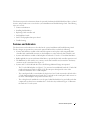 7
7
-
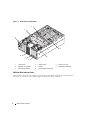 8
8
-
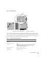 9
9
-
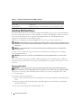 10
10
-
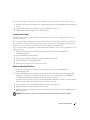 11
11
-
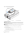 12
12
-
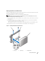 13
13
-
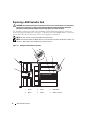 14
14
-
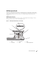 15
15
-
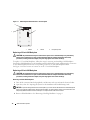 16
16
-
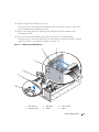 17
17
-
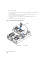 18
18
-
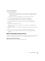 19
19
-
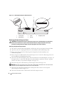 20
20
-
 21
21
-
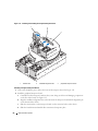 22
22
-
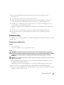 23
23
-
 24
24
-
 25
25
-
 26
26
-
 27
27
-
 28
28
-
 29
29
-
 30
30
-
 31
31
-
 32
32
-
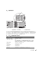 33
33
-
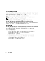 34
34
-
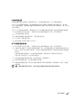 35
35
-
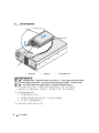 36
36
-
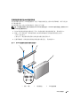 37
37
-
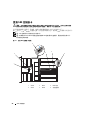 38
38
-
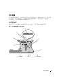 39
39
-
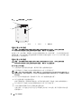 40
40
-
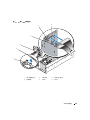 41
41
-
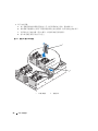 42
42
-
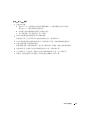 43
43
-
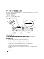 44
44
-
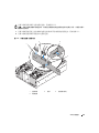 45
45
-
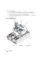 46
46
-
 47
47
-
 48
48
-
 49
49
-
 50
50
-
 51
51
-
 52
52
-
 53
53
-
 54
54
-
 55
55
-
 56
56
-
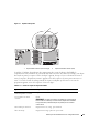 57
57
-
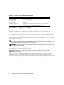 58
58
-
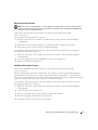 59
59
-
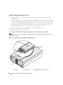 60
60
-
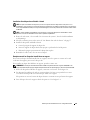 61
61
-
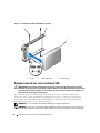 62
62
-
 63
63
-
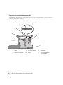 64
64
-
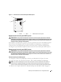 65
65
-
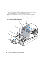 66
66
-
 67
67
-
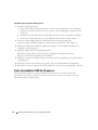 68
68
-
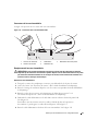 69
69
-
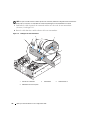 70
70
-
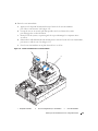 71
71
-
 72
72
-
 73
73
-
 74
74
-
 75
75
-
 76
76
-
 77
77
-
 78
78
-
 79
79
-
 80
80
-
 81
81
-
 82
82
-
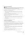 83
83
-
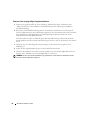 84
84
-
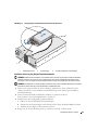 85
85
-
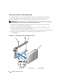 86
86
-
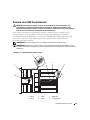 87
87
-
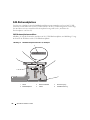 88
88
-
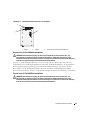 89
89
-
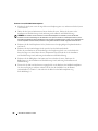 90
90
-
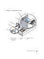 91
91
-
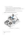 92
92
-
 93
93
-
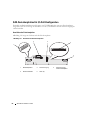 94
94
-
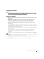 95
95
-
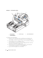 96
96
-
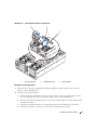 97
97
-
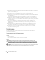 98
98
-
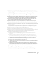 99
99
-
 100
100
-
 101
101
-
 102
102
-
 103
103
-
 104
104
-
 105
105
-
 106
106
-
 107
107
-
 108
108
-
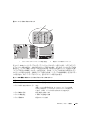 109
109
-
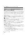 110
110
-
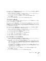 111
111
-
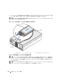 112
112
-
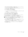 113
113
-
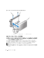 114
114
-
 115
115
-
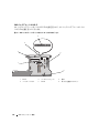 116
116
-
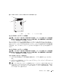 117
117
-
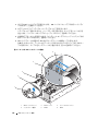 118
118
-
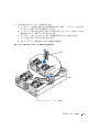 119
119
-
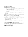 120
120
-
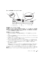 121
121
-
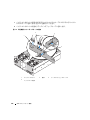 122
122
-
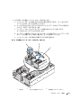 123
123
-
 124
124
-
 125
125
-
 126
126
-
 127
127
-
 128
128
-
 129
129
-
 130
130
-
 131
131
-
 132
132
-
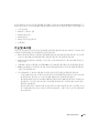 133
133
-
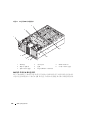 134
134
-
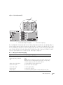 135
135
-
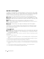 136
136
-
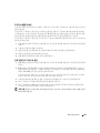 137
137
-
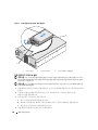 138
138
-
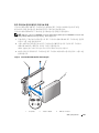 139
139
-
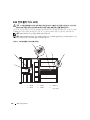 140
140
-
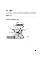 141
141
-
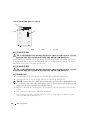 142
142
-
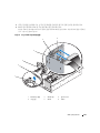 143
143
-
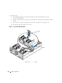 144
144
-
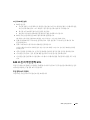 145
145
-
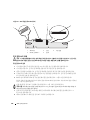 146
146
-
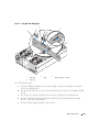 147
147
-
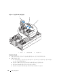 148
148
-
 149
149
-
 150
150
-
 151
151
-
 152
152
-
 153
153
-
 154
154
-
 155
155
-
 156
156
-
 157
157
-
 158
158
-
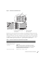 159
159
-
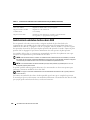 160
160
-
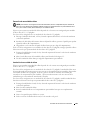 161
161
-
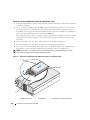 162
162
-
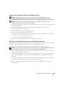 163
163
-
 164
164
-
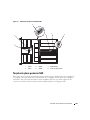 165
165
-
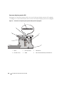 166
166
-
 167
167
-
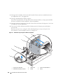 168
168
-
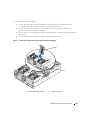 169
169
-
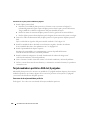 170
170
-
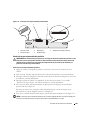 171
171
-
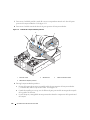 172
172
-
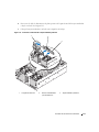 173
173
-
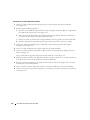 174
174
-
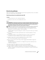 175
175
-
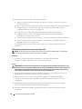 176
176
-
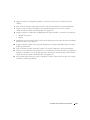 177
177
-
 178
178


en otros idiomas
- français: Dell PowerEdge 6850 Mode d'emploi
- Deutsch: Dell PowerEdge 6850 Benutzerhandbuch
- 日本語: Dell PowerEdge 6850 ユーザーガイド