Air King 4YN46C Manual de usuario
- Categoría
- Ventiladores domésticos
- Tipo
- Manual de usuario
Este manual también es adecuado para

Rev. F 4/01 4 2084576
READ AND SAVE THESE INSTRUCTIONS
READ CAREFULLY BEFORE ATTEMPTING TO ASSEMBLE, INSTALL, OPERATE OR MAINTAIN THE PRODUCT DESCRIBED.
PROTECT YOURSELF AND OTHERS BY OBSERVING ALL SAFETY INFORMATION. FAILURE TO COMPLY WITH
INSTRUCTIONS COULD RESULT IN PERSONAL INJURY AND/OR PROPERTY DAMAGE!
RETAIN INSTRUCTIONS FOR FUTURE REFERENCE.
DESCRIPTION
The AirKing 18" (45.7 cm) Multi Mount Fan features Pull Cord operation
and a 3-paddle Fan Blade. This Fan has a permanently lubricated motor
with a 9 ft (2.74 m) 18/3 cord set and are constructed of sturdy, powder
coated steel.
SPECIFICATIONS
Motor.......................................120V, 50/60 Hz (18", 45.7 cm)
Blade diameter .......................18" (45.7 cm) Model 4YN46C/9318C
Speeds....................................3
Control ....................................Pull Cord
Air flow distribution .................360°
Approvals................................UL Listed. Close mesh Fan guard
meets OSHA requirements.
HIGH VELOCITY
MULTI MOUNT FAN
18" (45.7 cm) MODEL 4YN46C/9318C
OPERATING INSTRUCTIONS & PARTS MANUAL
GENERAL SAFETY INFORMATION
1. Make certain that the power source conforms to the electrical require-
ments of the Fan.
2. The power cord is equipped with a three-prong grounded plug that must
be inserted into a matching receptacle. Under no circumstances must the
grounding prong be cut off the plug. Where a two-prong wall receptacle
is encountered, it must be replaced with a properly grounded three-prong
receptacle installed in accordance with the National Electrical Code
(NEC) and all applicable local codes and ordinances. This work must be
done only by a qualified electrician, using copper wire only.
WARNING: USE OF A THREE-PRONG TO TWO-PRONG ADAPTER IS
NOT RECOMMENDED. IMPROPER CONNECTION MAY CREATE THE
RISK OF ELECTROCUTION. USE OF SUCH ADAPTERS ARE NOT
PERMITTED IN CANADA.
MODELO 4YN46C/9318C
Rev. F 4/01 1 2084576
3. Where possible, avoid the use of extension cords. If they must be used,
minimize the risk of overheating by ensuring that they are UL listed and
of the proper gage and length. Never use a single extension cord to
operate more than one Fan.
4. Do not insert fingers or foreign objects into the Fan. Do not block or
tamper with the Fan in any manner while it is in operation. Do not touch
the Fan while in operation or just after it has been turned off, as some
parts may be hot enough to cause injury.
5. Unplug power cord before installing or servicing the Fan.
WARNING: DO NOT DEPEND UPON THE ON-OFF SWITCH AS THE
SOLE MEANS OF DISCONNECTING POWER WHEN INSTALLING OR
SERVICING THE FAN. ALWAYS UNPLUG THE POWER CORD.
6. This Fan is intended for general use ONLY. It must NOT be used in
potentially dangerous locations such as flammable, explosive, chemi-
cal-laden or wet atmospheres.
WARNING: TO REDUCE THE RISK OF FIRE OR ELECTRIC SHOCK,
DO NOT USE THIS FAN WITH ANY SOLID STATE SPEED CONTROL
DEVICE.
7. Be sure Fan is on a stable surface when operating, to avoid chance of
it overturning.
8. DO NOT use Fan in a window. Rain may create an electrical hazard.
9. Completely reassemble Fan, according to instructions before recon-
necting to power supply.
WALL/CEILING INSTALLATION
1. WOOD STRUCTURES: Locate the wall or ceiling stud nearest to
the desired Fan location. Attach the Fan to the stud using a 3/8"
diameter x 2" long Lag Screw (Not Supplied).
(Figure 1)
NOTE: ALWAYS INSTALL THE YOKE TO A MINIMUM OF 2 X 4
STUDDING.
2. STEEL STRUCTURES: Attach the Fan using a 3/8" bolt of the
appropriate length, with a Flat Washer, Lock Washer and a 3/8" Nut
(Not Supplied).
3. MASONARY STRUCTURES: Attach Fan using a 3/8" Lag Screw,
with a Lag Shield of appropriate length (Not Supplied).
(Figure 1)
NOTE: IN ALL CASES, IT IS RECOMMENDED THAT A FLAT WASHER
BE PLACED ON BOTH SIDES OF THE FAN YOKE TO ASSIST IN
SMOOTH ROTATION.
4. Attach Pull Cord String and Pendant to Switch.
Figure 1
Lag Screw
Wall or Ceiling Stud
Flat Washers
Lag Shield
(Masonary Only)
REF
NO.
NO. DE PARTE
DESCRIPCIÓN CANT.
OPERACIÓN
1. Enchufe el cable de conexión eléctrica dentro de un tomacorriente de tres
hojas conectado ampropiadamente a tierra.
2. Utilizando el cordón accionador, seleccione la velocidad deseada del Ventilador.
3. ADVERTENCIA: Este ventilador debe ser usa do solmente en unambiente
limpio y seco. Si producto esta montado de alguna otra manera espec´ifica que
indica la hoja de instrucción, purdiera anularse y no tener valor la garantia del
fabricante.
MANTENIMIENTO
ADVERTENCIA: DESCONECTE SIEMPRE EL CORDÓN ANTES DE
INTENTAR REALIZAR CUALQUIER FUNCIÓN DE SERVICIO.
LIMPIEZA: Use un trapo y una solución de jabón suave, tal como
detergente líquido para lavar trastes.
ADVERTENCIA: No use gasolina, bencina, diluyente de pintura ni
limpiadores fuertes en aerosol, ya que éstos dañarán el ventilador.
ALMACENAMIENTO: Cuando no lo utilice, mantenga el aparato en un
lugar limpio y seco.
EL MOTOR HA SIDO PERMANENTEMENTE LUBRICADO.
ATENCIÓN: EL CABLE DE APOYO SECUNDARIO SUMINISTRADO
DEBE UTILIZARSE CUANDO QUIERA QUE EL VENTILADOR SEA
MONTADO POR LO ALTO, PARA MAYOR SEGURIDAD.
CABLE DE APOYO SECUNDARIO
1. Entrelazar el cabo del Cable alrededor de los Alambres de Diámetro Grande
tanto por la Parte Delantera como por la Parte Trasera de la Defensa del
Ventilador.
(Figura 2)
2. Fijar la Mordaza del Cable de manera que la "U" del lado del cabo del bucle
quede con cabo de 1 a 2 pulgadas aproximadamente. Apretar las Tuercas
de la Mordaza. Hay que asegurarse de que ninguna parte del Cable
estorbe a la Paleta.
(Figura 2)
3. Enroscar el otra cabo del Cable alrededor de una viga o armazón segura
de la edificación, o de otro soporte cercano al Ventilador.
(Figura 3)
Recoger todo lo del cable que quede sobrando.
CUIDADO: UTILIZAR SÓLO LOS ELEMENTOS METÁLICOS DE
MONTAJE QUE SE RECOMIENDAN PARA ESTE VENTILADOR.
4. Fijar la Mordaza de Cable restante como se indica en la parte 2. Hay que
recortar el exceso de cabo de manera que sólo queden de 1 a 2 pulgadas
después de la Mordaza
5. Revisar el Ensamblado para cerciorarse de que la Paleta esté libre de toda
obstrucción.
ATENCIÓN: EL USO DEL CABLE DE APOYO SECUNDARIO NO
GARANTIZA LA PROTECCIÓN DE PERSONAS CONTRA LESIONES Y EL
MONTAJE DEL VENTILADOR Y DEL CABLE PODRÍAN DAÑARSE SI SE
MALTRATAN, SE DESCUIDAN O NO SE INSTALAN BIEN.
Alambres Grandes
de la Defensa
Figura 3
Figura 2
Cable de
Apoyo
Secundario
** Suministros por Bolso de Piezas Componentes Físicas (2098012)
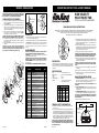
MODEL
4YN46C/9318C
SPEED
HIGH MED LOW
CFM 5350 4180 3010
M
3
/s 2.52 1.97 1.42
RPM 1600 1275 950
Amps 1.65 1.27 .95
Watts 194 148 110
dB A 67 58 49
24
23
21
9
10
22
14
13
12
1
20
16
7
8
5
4
3
6
2
11
10
8
9
19
17
18
15
15
22
17
1 2065510 Placa de Identificación 1
2 2050015 Cordón Eléctrico 1
3 2010636 Cubierta del Motor 1
4 2055001 Interruptor del Cordón Accionador 1
5 ** Cordón Accionador con Colgante 1
6 2090552 Tuerca para el Alambre 2
7 5096056B Rejilla Trasera 1
8 5060015 Placa de Pivote 2
9 2091162 Tornillo de #8 x 1/2 PPH Tipo F 4
10 2091126B Tornillo de #6 x 5/8" PTH 3
11 2030021SB Motor 1
12 5081050B Hélice 1
13 5090044 Tornillo Prisionero de 1/4-28 x 3/8 1
14 5060027 Horqueta 1
15 5090041 Remache 2
16 2011601 Espaciador de Caucho 2
17 2091143 Tornillo de #8 x 3/8" PPH Type F 4
18 5096052BK Rejilla Delantera 1
19 2090547 Contratuerca 3
20 2010237L Adorno de Protección 1
21 2070027 Ojo de Buey 1
22 5090045 #10-32 x 1/2 MWM SERR F-ZP
23 ** Grapa de Cable 2
24 ** Cable de Seguridad 1

MODEL 4YN46C/9318C
LEA Y GUARDE ESTAS INSTRUCCIONES
LÉALAS CUIDADOSAMENTE ANTES DE INTENTAR ARMAR, INSTALAR, OPERAR O DAR MANTENIMIENTO AL PRODUCTO DESCRITO.
PROTÉJASE A SÍ MISMO Y A LOS DEMÁS OBSERVANDO TODA LA INFORMACIÓN SOBRE SEGURIDAD. ¡NO SEGUIR LAS
INSTRUCCIONES PODRÍA RESULTAR EN LESIONES PERSONALES Y/O DAÑOS A LA PROPIEDAD!
GUARDE LAS INSTRUCCIONES PARA REFERENCIAS FUTURAS.
INFORMACIÓN GENERAL SOBRE SEGURIDAD
1. Cerciórese de que la fuente de electricidad se adapte a los requerimientos
eléctricos del ventilador.
2. El cordón eléctrico está equipado con una clavija a tierra de tres espigas
que tiene que ser enchufada a un receptáculo del mismo diseño. Bajo
ninguna circunstancia deberá cortarse la espiga a tierra de la clavija. De
existir un receptáculo de pared de dos espigas, deberá reemplazarse por
uno de tres espigas debidamente puesto a tierra e instalado de conformidad
con el Código Nacional de Electricidad y todos los códigos y ordenanzas
locales aplicables. El trabajo deberá hacerlo un electricista calificado,
utilizando exclusivamente alambre de cobre.
ADVERTENCIA: NO SE RECOMIENDA EL USO DE UN ADAPTADOR DE
TRES A DOS ESPIGAS. LA CONEXIÓN INDEBIDA PODRÍA CREAR EL
RIESGO DE SER ELECTROCUTADO. EL USO DE TALES ADAPTADORES
NO ESTÁ PERMITIDO EN CANADÁ.
MANUAL DE INSTRUCCIONES DE OPERACIÓN Y PARTES
DESCRIPCIÓN
AirKing de ventilador para piso o para mesa y de 18" (45.7 cm) se caracteriza
por el funcionamiento silencioso como murmullo con paleta de ventilador
dividida en tres. Tiene motor lubricado permanentemente con juego de
alambre 18/3 de 9 pies (2.7 m).
ESPECIFICACIONES
Motor............................................... 120V, 50/60Hz (18", 45.7 cm)
Tamaño de paletas......................... 18" (45.7 cm) Modelo 4YN46C/9318C
Velocidades .................................... 3
Control ............................................ Cordón Accionador
Distribución del lujo de aire............ 360°
Aprobaciones................. Catalogación UL. El protector de malla cerrada
del ventilador satisface las normas OSHA.
3. Siempre que sea posible, evite el uso de extensiones eléctricas. Si tienen
que usarse, minimice el riesgo de sobrecalentamiento asegurándose de
que sean de catalogación UL y del calibre y la longitud adecuadas. Nunca
use una sola extensión para operar más de un ventilador.
4. No introduzca los dedos ni objetos extraños en el ventilador. No obstruya
ni manipule indebidamente el ventilador mientras esté en operación. No
toque el ventilador mientras esté en operación ni inmediatamente después
de haberlo apagado, ya que ciertas partes podrían estar lo suficientemente
calientes como para causar una lesión.
5. Desenchufe el cordón eléctrico antes de instalar o dar servicio al ventilador.
ADVERTENCIA: NO DEPENDA DEL INTERRUPTOR DE ENCENDIDO Y
APAGADO COMO EL ÚNICO MEDIO PARA INTERRUMPIR LA
ALIMENTACIÓN ELÉCTRICA CUANDO INSTALE O DÉ SERVICIO AL
VENTILADOR. SIEMPRE DESENCHUFE EL CORDÓN ELÉCTRICO.
6. Este ventilador es para uso general EXCLUSIVAMENTE. NO deberá
usarse en localidades potencialmente peligrosas tales como atmósferas
inflamables, explosivas, cargadas de gases o húmedas.
ADVERTENCIA: PARA REDUCIR EL RIESGO DE INCENDIOS O
DESCARGAS ELÉCTRICAS, NO USE ESTE VENTILADOR CON NINGÚN
DISPOSITIVO DE CONTROL DE VELOCIDAD DE ESTADO SÓLIDO.
7. Asegúrese de que el ventilador esté sobre una superficie estable al estar
en funcionamiento, para evitar toda riesgo de que se voltee.
8. NO utilice el ventilador en una ventana, ya que la lluvia podría crear un
peligro eléctrico.
9. Vuelva a armar completamente el ventilador, de acuerdo con las
instrucciones, antes de volver a conectarlo a la alimentación eléctrica
INSTALACIÓN EN PAREDES / TECHOS
1. ESTRUCTURAS DE MADERA: Localice el montante de pared o techo
más cercano a la ubicación deseada para el Ventilador. Una el Ventilador
al montante, usando uno Tornillo de Retraso de 5/16" de dimetro x 2" de
longitud (No Proporcionados).
(Figura 1)
NOTA: SIEMPRE INSTALE LA HORQUETA EN MONTANTES DE 2 X 4
COMO MÍNIMO.
2. ESTRUCTURAS DE ACERO: Fijar el Ventilador con un perno de 3/8"
de longitud adecuada, con Arandela Plana, Arandela de Seguridad y
Tuerca de 3/8" (No Suministrada).
3. ESTRUCTURAS DE MAMPOSTERÍA: Fijar el Ventilador con un
Tornillo Tipo Tirafondo de 3/8", con Maguito de Expansión de longitud
adecuada (No Suministrado).
(Figura 1)
NOTA: EN TODOS LOS CASOS SE RECOMIENDA QUE SE COLOQUE
UNA ARANDELA PLANA EN AMBOS LADOS DE LA HORQUILLA DEL
VENTILADOR PARA CONTRIBUIR A QUE EL GIRO SEA SUAVE.
4. Fije el cordón accionador y la pieza colgante con el interruptor.
VENTILADOR DE ALTA
VELOCIDAD Y MONTAJE
MÚLTIPLE
18" (45.7 cm) MODELO 4YN46C/9318C
Rev. F 4/01 2 2084576 Rev. F 4/01 3 2084576
KEY PART NO. DESCRIPTION QTY.
Figura 1
Tornillo de
Retraso
Montante de Techo o Pared
Arandela Plana
Manguito de Expansión
(Sólo para Mampostería)
CAUTION: THE SECONDARY SUPPORT CABLE PROVIDED
SHOULD BE USED ANYTIME THE CIRCULATOR IS MOUNTED
OVERHEAD FOR ADDITIONAL SAFETY.
SECONDARY SUPPORT CABLE
1. Loop one end of Cable around the Large Diameter Wires of both the
Front and Rear Circulator Guard.
(Figure 2)
2. Attach a Cable Clamp with the "U" on the tail side of the loop leaving
a tail approximately 1 to 2 inches. Tighten Clamp Nuts. Make sure no
part of the Cable interferes with the Blade.
(Figure 2)
3. Wrap the other end of the Cable around a secure building joist, truss,
or other support near the Fan.
(Figure 3)
Take up all excess slack in
the Cable.
CAUTION: USE ONLY THE MOUNTING HARDWARE WHICH
IS RECOMMENDED FOR USE ON THIS FAN.
4. Attach the remaining Cable Clamp as indicated in
Step 2
. The excess
tail should be trimmed to extend 1 to 2 inches past the Clamp.
5. Check the Assembly to assure the Blade is free of all obstructions.
CAUTION: USE OF THE SECONDARY SUPPORT CABLE DOES NOT
GUARANTEE PROTECTION AGAINST INJURY OF PERSONS,
MOUNTING OF BOTH THE CIRCULATOR AND CABLE COULD FAIL
IF SUBJECTED TO ABUSE, NEGLECT OR IMPROPER INSTALLATION.
Large Guard Wires
Figure 3
Figure 2
OPERATION
1. Plug the power cord into a properly grounded three-prong receptacle.
2. Using the Pull Cord Switch, set the desired Fan Speed.
3. WARNING: This fan should be used only in a clean, dry environment.
Mounting of this product in any way other then specified in the instruc-
tion sheet will null and void the manufacturers warranty
..
MAINTENANCE
WARNING: ALWAYS UNPLUG CORD BEFORE SERVICING.
CLEANING: Use a soft cloth and a mild soap solution such as liquid dish
washing detergent.
CAUTION: Do not use gasoline, benzine, thinner, harsh cleaners,
etc. which will damage the Fan.
Dry all parts with a soft cloth completely before reconnecting to power supply.
STORAGE: When not in use, keep unit in a clean dry place.
MOTOR IS PERMANENTLY LUBRICATED.
** Supplied in Hardware Bag (2098012)
Secondary
Support
Cable
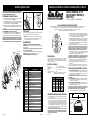
1 2065510 Name Plate 1
2 2050015 Cord Set 1
3 2010636 Motor Cover 1
4 2055001 Pull Cord Switch 1
5 ** Pull Cord with Pendant 1
6 2090552 Wire Nut 2
7 5096056B Rear Grill 1
8 5060015 Pivot Bracket 2
9 2091162 Screw #8 x 1/2 PPH Type F 4
10 2091126B Screw #6 x 5/8" PTH 3
11 2030021SB Motor 1
12 5081050B Blade 1
13 5090044 Set Screw 1/4-28 x 3/8 1
14 5060027 Yoke 1
15 5090041 Rivet 2
16 2011601 Rubber spacer 2
17 2091143 Screw #8 x 3/8" PPH Type F 4
18 5096052BK Front Grill 1
19 2090547 Palnut 3
20 2010237L Guard Ornament 1
21 2070027 Bullseye 1
22 5090045 #10-32 x 1/2 MWM SERR F-ZP
23 ** Cable Lock 2
24 ** Safety Cable 1
MODELO
4YN46C/9318C
VELOCIDAD
ALTA MEDIA BAJA
CFM 5350 4180 3010
M
3
/s 2.52 1.97 1.42
RPM 600 1275 950
Amps .65 1.27 .95
Watts 194 148 110
dB A 67 58 49
24
23
21
9
10
22
14
13
12
1
20
16
7
8
5
4
3
6
2
11
10
8
9
19
17
18
15
15
22
17
Transcripción de documentos
OPERATING INSTRUCTIONS & PARTS MANUAL MODELO 4YN46C/9318C ATENCIÓN: EL CABLE DE APOYO SECUNDARIO SUMINISTRADO DEBE UTILIZARSE CUANDO QUIERA QUE EL VENTILADOR SEA MONTADO POR LO ALTO, PARA MAYOR SEGURIDAD. CABLE DE APOYO SECUNDARIO Alambres Grandes de la Defensa 1. Entrelazar el cabo del Cable alrededor de los Alambres de Diámetro Grande tanto por la Parte Delantera como por la Parte Trasera de la Defensa del Ventilador. (Figura 2) 2. Fijar la Mordaza del Cable de manera que la "U" del lado del cabo del bucle quede con cabo de 1 a 2 pulgadas aproximadamente. Apretar las Tuercas de la Mordaza. Hay que asegurarse de que ninguna parte del Cable estorbe a la Paleta. (Figura 2) 3. Enroscar el otra cabo del Cable alrededor de una viga o armazón segura de la edificación, o de otro soporte cercano al Ventilador. (Figura 3) Recoger todo lo del cable que quede sobrando. CUIDADO: UTILIZAR SÓLO LOS ELEMENTOS METÁLICOS DE MONTAJE QUE SE RECOMIENDAN PARA ESTE VENTILADOR. 4. Fijar la Mordaza de Cable restante como se indica en la parte 2. Hay que recortar el exceso de cabo de manera que sólo queden de 1 a 2 pulgadas después de la Mordaza 5. Revisar el Ensamblado para cerciorarse de que la Paleta esté libre de toda obstrucción. ATENCIÓN: EL USO DEL CABLE DE APOYO SECUNDARIO NO GARANTIZA LA PROTECCIÓN DE PERSONAS CONTRA LESIONES Y EL MONTAJE DEL VENTILADOR Y DEL CABLE PODRÍAN DAÑARSE SI SE MALTRATAN, SE DESCUIDAN O NO SE INSTALAN BIEN. 17 1 9 20 18 OPERACIÓN 8 3 MANTENIMIENTO ADVERTENCIA: DESCONECTE SIEMPRE EL CORDÓN ANTES DE INTENTAR REALIZAR CUALQUIER FUNCIÓN DE SERVICIO. LIMPIEZA: Use un trapo y una solución de jabón suave, tal como detergente líquido para lavar trastes. ADVERTENCIA: No use gasolina, bencina, diluyente de pintura ni limpiadores fuertes en aerosol, ya que éstos dañarán el ventilador. ALMACENAMIENTO: Cuando no lo utilice, mantenga el aparato en un lugar limpio y seco. EL MOTOR HA SIDO PERMANENTEMENTE LUBRICADO. 21 1 2 3 4 5 6 7 8 9 10 11 12 13 14 15 16 17 18 19 20 21 22 23 24 15 4 22 12 14 13 10 1 9 8 2 5 6 23 24 2065510 2050015 2010636 2055001 ** 2090552 5096056B 5060015 2091162 2091126B 2030021SB 5081050B 5090044 5060027 5090041 2011601 2091143 5096052BK 2090547 2010237L 2070027 5090045 ** ** DESCRIPCIÓN CANT. Placa de Identificación Cordón Eléctrico Cubierta del Motor Interruptor del Cordón Accionador Cordón Accionador con Colgante Tuerca para el Alambre Rejilla Trasera Placa de Pivote Tornillo de #8 x 1/2 PPH Tipo F Tornillo de #6 x 5/8" PTH Motor Hélice Tornillo Prisionero de 1/4-28 x 3/8 Horqueta Remache Espaciador de Caucho Tornillo de #8 x 3/8" PPH Type F Rejilla Delantera Contratuerca Adorno de Protección Ojo de Buey #10-32 x 1/2 MWM SERR F-ZP Grapa de Cable Cable de Seguridad 1 1 1 1 1 2 1 2 4 3 1 1 1 1 2 2 4 1 3 1 1 2 1 ** Suministros por Bolso de Piezas Componentes Físicas (2098012) Rev. F 4/01 3. Where possible, avoid the use of extension cords. If they must be used, minimize the risk of overheating by ensuring that they are UL listed and of the proper gage and length. Never use a single extension cord to operate more than one Fan. 4. Do not insert fingers or foreign objects into the Fan. Do not block or tamper with the Fan in any manner while it is in operation. Do not touch the Fan while in operation or just after it has been turned off, as some parts may be hot enough to cause injury. 5. Unplug power cord before installing or servicing the Fan. WARNING: DO NOT DEPEND UPON THE ON-OFF SWITCH AS THE SOLE MEANS OF DISCONNECTING POWER WHEN INSTALLING OR SERVICING THE FAN. ALWAYS UNPLUG THE POWER CORD. 6. This Fan is intended for general use ONLY. It must NOT be used in potentially dangerous locations such as flammable, explosive, chemical-laden or wet atmospheres. WARNING: TO REDUCE THE RISK OF FIRE OR ELECTRIC SHOCK, DO NOT USE THIS FAN WITH ANY SOLID STATE SPEED CONTROL DEVICE. 7. Be sure Fan is on a stable surface when operating, to avoid chance of it overturning. 8. DO NOT use Fan in a window. Rain may create an electrical hazard. 9. Completely reassemble Fan, according to instructions before reconnecting to power supply. 3. ADVERTENCIA: Este ventilador debe ser usa do solmente en unambiente limpio y seco. Si producto esta montado de alguna otra manera espec´ifica que indica la hoja de instrucción, purdiera anularse y no tener valor la garantia del fabricante. 17 10 RETAIN INSTRUCTIONS FOR FUTURE REFERENCE. 1. Enchufe el cable de conexión eléctrica dentro de un tomacorriente de tres hojas conectado ampropiadamente a tierra. 2. Utilizando el cordón accionador, seleccione la velocidad deseada del Ventilador. 16 22 9 18" (45.7 cm) MODEL 4YN46C/9318C READ CAREFULLY BEFORE ATTEMPTING TO ASSEMBLE, INSTALL, OPERATE OR MAINTAIN THE PRODUCT DESCRIBED. PROTECT YOURSELF AND OTHERS BY OBSERVING ALL SAFETY INFORMATION. FAILURE TO COMPLY WITH INSTRUCTIONS COULD RESULT IN PERSONAL INJURY AND/OR PROPERTY DAMAGE! REF NO. NO. DE PARTE 11 Cable de Apoyo Secundario READ AND SAVE THESE INSTRUCTIONS 15 7 HIGH VELOCITY MULTI MOUNT FAN Figura 3 Figura 2 4 2084576 DESCRIPTION The AirKing 18" (45.7 cm) Multi Mount Fan features Pull Cord operation and a 3-paddle Fan Blade. This Fan has a permanently lubricated motor with a 9 ft (2.74 m) 18/3 cord set and are constructed of sturdy, powder coated steel. SPECIFICATIONS Motor ....................................... 120V, 50/60 Hz (18", 45.7 cm) Blade diameter ....................... 18" (45.7 cm) Model 4YN46C/9318C Speeds .................................... 3 Control .................................... Pull Cord Air flow distribution ................. 360° Approvals ................................ UL Listed. Close mesh Fan guard meets OSHA requirements. MODEL WALL/CEILING INSTALLATION 1. WOOD STRUCTURES: Locate the wall or ceiling stud nearest to the desired Fan location. Attach the Fan to the stud using a 3/8" diameter x 2" long Lag Screw (Not Supplied). (Figure 1) NOTE: ALWAYS INSTALL THE YOKE TO A MINIMUM OF 2 X 4 STUDDING. 2. STEEL STRUCTURES: Attach the Fan using a 3/8" bolt of the appropriate length, with a Flat Washer, Lock Washer and a 3/8" Nut (Not Supplied). 3. MASONARY STRUCTURES: Attach Fan using a 3/8" Lag Screw, with a Lag Shield of appropriate length (Not Supplied). (Figure 1) NOTE: IN ALL CASES, IT IS RECOMMENDED THAT A FLAT WASHER BE PLACED ON BOTH SIDES OF THE FAN YOKE TO ASSIST IN SMOOTH ROTATION. 4. Attach Pull Cord String and Pendant to Switch. 4YN46C/9318C SPEED HIGH MED LOW CFM M3/s RPM Amps Watts dB A 5350 2.52 1600 1.65 194 67 4180 1.97 1275 1.27 148 58 3010 1.42 950 .95 110 49 Wall or Ceiling Stud GENERAL SAFETY INFORMATION 1. Make certain that the power source conforms to the electrical requirements of the Fan. 2. The power cord is equipped with a three-prong grounded plug that must be inserted into a matching receptacle. Under no circumstances must the grounding prong be cut off the plug. Where a two-prong wall receptacle is encountered, it must be replaced with a properly grounded three-prong receptacle installed in accordance with the National Electrical Code (NEC) and all applicable local codes and ordinances. This work must be done only by a qualified electrician, using copper wire only. WARNING: USE OF A THREE-PRONG TO TWO-PRONG ADAPTER IS NOT RECOMMENDED. IMPROPER CONNECTION MAY CREATE THE RISK OF ELECTROCUTION. USE OF SUCH ADAPTERS ARE NOT PERMITTED IN CANADA. Rev. F 4/01 Lag Shield (Masonary Only) Flat Washers Lag Screw Figure 1 1 2084576 MANUAL DE INSTRUCCIONES DE OPERACIÓN Y PARTES MODEL 4YN46C/9318C CAUTION: THE SECONDARY SUPPORT CABLE PROVIDED SHOULD BE USED ANYTIME THE CIRCULATOR IS MOUNTED OVERHEAD FOR ADDITIONAL SAFETY. SECONDARY SUPPORT CABLE Secondary Support Cable Large Guard Wires 1. Loop one end of Cable around the Large Diameter Wires of both the Front and Rear Circulator Guard. (Figure 2) 2. Attach a Cable Clamp with the "U" on the tail side of the loop leaving a tail approximately 1 to 2 inches. Tighten Clamp Nuts. Make sure no part of the Cable interferes with the Blade. (Figure 2) 3. Wrap the other end of the Cable around a secure building joist, truss, or other support near the Fan. (Figure 3) Take up all excess slack in the Cable. CAUTION: USE ONLY THE MOUNTING HARDWARE WHICH IS RECOMMENDED FOR USE ON THIS FAN. 4. Attach the remaining Cable Clamp as indicated in Step 2. The excess tail should be trimmed to extend 1 to 2 inches past the Clamp. 5. Check the Assembly to assure the Blade is free of all obstructions. CAUTION: USE OF THE SECONDARY SUPPORT CABLE DOES NOT GUARANTEE PROTECTION AGAINST INJURY OF PERSONS, MOUNTING OF BOTH THE CIRCULATOR AND CABLE COULD FAIL IF SUBJECTED TO ABUSE, NEGLECT OR IMPROPER INSTALLATION. VENTILADOR DE ALTA VELOCIDAD Y MONTAJE MÚLTIPLE Figure 3 Figure 2 18" (45.7 cm) MODELO 4YN46C/9318C LEA Y GUARDE ESTAS INSTRUCCIONES LÉALAS CUIDADOSAMENTE ANTES DE INTENTAR ARMAR, INSTALAR, OPERAR O DAR MANTENIMIENTO AL PRODUCTO DESCRITO. PROTÉJASE A SÍ MISMO Y A LOS DEMÁS OBSERVANDO TODA LA INFORMACIÓN SOBRE SEGURIDAD. ¡NO SEGUIR LAS INSTRUCCIONES PODRÍA RESULTAR EN LESIONES PERSONALES Y/O DAÑOS A LA PROPIEDAD! GUARDE LAS INSTRUCCIONES PARA REFERENCIAS FUTURAS. OPERATION 1. Plug the power cord into a properly grounded three-prong receptacle. 2. Using the Pull Cord Switch, set the desired Fan Speed. 3. Siempre que sea posible, evite el uso de extensiones eléctricas. Si tienen que usarse, minimice el riesgo de sobrecalentamiento asegurándose de que sean de catalogación UL y del calibre y la longitud adecuadas. Nunca use una sola extensión para operar más de un ventilador. 4. No introduzca los dedos ni objetos extraños en el ventilador. No obstruya ni manipule indebidamente el ventilador mientras esté en operación. No toque el ventilador mientras esté en operación ni inmediatamente después de haberlo apagado, ya que ciertas partes podrían estar lo suficientemente calientes como para causar una lesión. 5. Desenchufe el cordón eléctrico antes de instalar o dar servicio al ventilador. ADVERTENCIA: NO DEPENDA DEL INTERRUPTOR DE ENCENDIDO Y APAGADO COMO EL ÚNICO MEDIO PARA INTERRUMPIR LA ALIMENTACIÓN ELÉCTRICA CUANDO INSTALE O DÉ SERVICIO AL VENTILADOR. SIEMPRE DESENCHUFE EL CORDÓN ELÉCTRICO. 6. Este ventilador es para uso general EXCLUSIVAMENTE. NO deberá usarse en localidades potencialmente peligrosas tales como atmósferas inflamables, explosivas, cargadas de gases o húmedas. ADVERTENCIA: PARA REDUCIR EL RIESGO DE INCENDIOS O DESCARGAS ELÉCTRICAS, NO USE ESTE VENTILADOR CON NINGÚN DISPOSITIVO DE CONTROL DE VELOCIDAD DE ESTADO SÓLIDO. 7. Asegúrese de que el ventilador esté sobre una superficie estable al estar en funcionamiento, para evitar toda riesgo de que se voltee. 8. NO utilice el ventilador en una ventana, ya que la lluvia podría crear un peligro eléctrico. 9. Vuelva a armar completamente el ventilador, de acuerdo con las instrucciones, antes de volver a conectarlo a la alimentación eléctrica 3. WARNING: This fan should be used only in a clean, dry environment. Mounting of this product in any way other then specified in the instruction sheet will null and void the manufacturers warranty.. MAINTENANCE 17 1 9 20 18 WARNING: ALWAYS UNPLUG CORD BEFORE SERVICING. CLEANING: Use a soft cloth and a mild soap solution such as liquid dish washing detergent. CAUTION: Do not use gasoline, benzine, thinner, harsh cleaners, etc. which will damage the Fan. Dry all parts with a soft cloth completely before reconnecting to power supply. STORAGE: When not in use, keep unit in a clean dry place. MOTOR IS PERMANENTLY LUBRICATED. 21 15 DESCRIPCIÓN AirKing de ventilador para piso o para mesa y de 18" (45.7 cm) se caracteriza por el funcionamiento silencioso como murmullo con paleta de ventilador dividida en tres. Tiene motor lubricado permanentemente con juego de alambre 18/3 de 9 pies (2.7 m). 7 8 16 11 17 KEY PART NO. 15 10 3 ESPECIFICACIONES 22 9 4 22 12 1 2 3 4 5 6 7 8 9 10 11 12 13 14 15 16 17 18 19 20 21 22 23 24 14 13 10 1 9 8 2 5 6 23 24 2065510 2050015 2010636 2055001 ** 2090552 5096056B 5060015 2091162 2091126B 2030021SB 5081050B 5090044 5060027 5090041 2011601 2091143 5096052BK 2090547 2010237L 2070027 5090045 ** ** DESCRIPTION Name Plate Cord Set Motor Cover Pull Cord Switch Pull Cord with Pendant Wire Nut Rear Grill Pivot Bracket Screw #8 x 1/2 PPH Type F Screw #6 x 5/8" PTH Motor Blade Set Screw 1/4-28 x 3/8 Yoke Rivet Rubber spacer Screw #8 x 3/8" PPH Type F Front Grill Palnut Guard Ornament Bullseye #10-32 x 1/2 MWM SERR F-ZP Cable Lock Safety Cable QTY. 1 1 1 1 1 2 1 2 4 3 1 1 1 1 2 2 4 1 3 1 1 2 1 ** Supplied in Hardware Bag (2098012) Rev. F 4/01 2 2084576 Motor ............................................... 120V, 50/60Hz (18", 45.7 cm) Tamaño de paletas ......................... 18" (45.7 cm) Modelo 4YN46C/9318C Velocidades .................................... 3 Control ............................................ Cordón Accionador Distribución del lujo de aire ............ 360° Aprobaciones ................. Catalogación UL. El protector de malla cerrada del ventilador satisface las normas OSHA. MODELO VELOCIDAD CFM M3/s RPM Amps Watts dB A INSTALACIÓN EN PAREDES / TECHOS 1. ESTRUCTURAS DE MADERA: Localice el montante de pared o techo más cercano a la ubicación deseada para el Ventilador. Una el Ventilador al montante, usando uno Tornillo de Retraso de 5/16" de dimetro x 2" de longitud (No Proporcionados). (Figura 1) NOTA: SIEMPRE INSTALE LA HORQUETA EN MONTANTES DE 2 X 4 COMO MÍNIMO. 2. ESTRUCTURAS DE ACERO: Fijar el Ventilador con un perno de 3/8" de longitud adecuada, con Arandela Plana, Arandela de Seguridad y Tuerca de 3/8" (No Suministrada). 3. ESTRUCTURAS DE MAMPOSTERÍA: Fijar el Ventilador con un Tornillo Tipo Tirafondo de 3/8", con Maguito de Expansión de longitud adecuada (No Suministrado). (Figura 1) NOTA: EN TODOS LOS CASOS SE RECOMIENDA QUE SE COLOQUE UNA ARANDELA PLANA EN AMBOS LADOS DE LA HORQUILLA DEL VENTILADOR PARA CONTRIBUIR A QUE EL GIRO SEA SUAVE. 4. Fije el cordón accionador y la pieza colgante con el interruptor. 4YN46C/9318C ALTA MEDIA BAJA 5350 2.52 600 .65 194 67 4180 1.97 1275 1.27 148 58 3010 1.42 950 .95 110 49 Montante de Techo o Pared INFORMACIÓN GENERAL SOBRE SEGURIDAD 1. Cerciórese de que la fuente de electricidad se adapte a los requerimientos eléctricos del ventilador. 2. El cordón eléctrico está equipado con una clavija a tierra de tres espigas que tiene que ser enchufada a un receptáculo del mismo diseño. Bajo ninguna circunstancia deberá cortarse la espiga a tierra de la clavija. De existir un receptáculo de pared de dos espigas, deberá reemplazarse por uno de tres espigas debidamente puesto a tierra e instalado de conformidad con el Código Nacional de Electricidad y todos los códigos y ordenanzas locales aplicables. El trabajo deberá hacerlo un electricista calificado, utilizando exclusivamente alambre de cobre. ADVERTENCIA: NO SE RECOMIENDA EL USO DE UN ADAPTADOR DE TRES A DOS ESPIGAS. LA CONEXIÓN INDEBIDA PODRÍA CREAR EL RIESGO DE SER ELECTROCUTADO. EL USO DE TALES ADAPTADORES NO ESTÁ PERMITIDO EN CANADÁ. Rev. F 4/01 Manguito de Expansión (Sólo para Mampostería) Arandela Plana Tornillo de Retraso Figura 1 3 2084576-
 1
1
-
 2
2


Air King 4YN46C Manual de usuario
- Categoría
- Ventiladores domésticos
- Tipo
- Manual de usuario
- Este manual también es adecuado para
En otros idiomas
- English: Air King 4YN46C User manual
Documentos relacionados
-
Air King 4TM61C/9020C Manual de usuario
-
Air King 9314 Manual de usuario
-
-
-
Air King 9518 Manual de usuario
-
-
Air King 9318 Manual de usuario
-
Air King 9219 Manual de usuario
-