Akron 3578 STREAMMASTER Installation, Operating And Maintenance Instructions
- Tipo
- Installation, Operating And Maintenance Instructions

TABLE OF CONTENTS
STYLE 3578 STREAMMASTER™
INSTALLATION, OPERATING, AND MAINTENANCE INSTRUCTIONS
WITH POSITION FEEDBACK
120356
English .................................................................1 - 14
Français ..............................................................15 - 28
Deutsch ..............................................................29 - 42
中文 (Chinese) ........................................................43 - 56
Español De América Latina (Spanish Latin America) ......................57 - 70


STYLE 3578 STREAMMASTER™
INSTALLATION, OPERATING, AND MAINTENANCE INSTRUCTIONS WITH
POSITION FEEDBACK
The following is intended to provide the basic instructions for installation, operation and maintenance of the
StreamMaster electric monitor, and to assist in attaining the best possible performance from the unit. Read and
understand these operating instructions before use.
TOOLS REQUIRED
• Utility Knife • Medium flat screwdriver
• Medium Phillips screwdriver • Small flat screwdriver
• Small Phillips screwdriver • 1/2 inch hex head wrench
• Electrician’s pliers (multipurpose, stripping and crimping)
PRODUCT RATINGS
Maximum Motor Current Draw:
12 volt versions 14.0 amps each for elevation and rotation motors
3.0 amps for nozzle pattern motor
24 volt versions 7.5 amps each for elevation and rotation motors
1.5 amps for nozzle pattern motor
Normal Operating Current: (Depending on operating conditions–pressure, flow, etc.)
12 volt versions
3.0 to 10.0 amps each for elevation and rotation
0.7 amps for nozzle pattern motor
24 volt versions 2 - 5 amps each for elevation and rotation motors
0.4 amps for nozzle pattern motor
Minimum Voltage: (Truck engine must be operating for proper voltage requirement.)
All 12 volt motors: 11.5 volts while operating
All 24 volt motors: 23 volts while operating
Mass: 39 lbs. (17.7 kg)
Maximum Flow: 2000 gpm (7600 lpm)
Maximum Pressure: 200 psi (14 bar)
Noise Emission: 95 DL @ 1m with maximum flow
PRODUCT WARNINGS
WARNING: Charge the unit slowly. Rapid charging may cause a pressure surge that has the potential to cause an injury, or dam-
age the monitor.
WARNING: DO NOT stow or deploy the StreamMaster monitor while flowing. Pressing the stow or deploy buttons causes the
nozzle to move automatically and the water stream may cause damage to equipment or injury to personnel.
WARNING: Aim the unit in a safe direction before pumping water through it. (i.e. Away from power lines)
WARNING: Although the circuit board includes a water-resistant coating, it is important to keep water out of the
control box and logic box. Prolonged exposure to water will cause damage.
120356

Page 2
WARNING: When the cover of the control box or logic box is removed, check that the O-ring under the cover is
intact and free of dirt and debris.
WARNING: The StreamMaster monitor uses current limiting for both the monitor and nozzle. Use only appropriate
Akron Brass Company nozzles.
WARNING: Do not use the electric controls when the override cranks are being used or are in position for use.
WARNING: Make the connection of the vehicle and auxiliary battery the final step.
WARNING: Replace the identification tags if they should become worn or damaged.
WARNING: DO NOT exceed the maximum pressure or flow ratings of the monitor. Exceeding these ratings may lead
to an injury or may cause damage to the monitor.
WARNING: DO NOT install shutos on the outlet of the monitor. Shutos increase the potential for pressure surges
due to water hammer, which have the potential to cause an injury or damage to the monitor.
WARNING: The StreamMaster monitor, nozzle, logic box, control box, tether controller, and field adjustable stops are
made for optimal performance. Do not alter in any manner.
WARNING: The StreamMaster monitor was designed for use with the Akromatic nozzle. Use of any other nozzle
could aect the speed or operation of the unit and should be tested before being put into service.
WARNING: The StreamMaster monitor contains moving parts. Keep hand, finger and objects away from pinch
points (Figure 1).
WARNING: Disconnect power and disable flow before maintenance.
WARNING: Keep all personnel out of the Danger Zone (Figure 2), in front of the outlet of the monitor
when the water source is attached. Dangerous flow velocities can cause serious injury.
WARNING: Not designed for explosive environments.
GENERAL INSTRUCTIONS
• Review the instructions, wiring diagram, component layout and rotational stops diagram before installing this unit.
This unit operates on 12 volt DC or 24 volt DC depending on the unit chosen. All electrical current flows through
the wires. The monitor does not act as a ground. The wires from the control boxes can be cut to the length for the
application plus 10 inches (See STEP 2). Do not extend the wires from the logic box to the monitor.
• The optional auxiliary battery is used for power failures and to ensure that the proper voltage and current are
maintained at the logic box when using a smaller gauge wire (12 Awg) for the power leads (vehicle battery).
If the optional auxiliary battery is used, do not extend the auxiliary battery wires. This will ensure that the
proper voltage and current are maintained at the monitor for it to operate properly. The optional battery is
automatically recharged by the truck electrical system through the positive (auxiliary battery) and ground
connections on the circuit board (Figure 6). The vehicle battery connections must have power turned on
whenever the truck is running so that the battery can be recharged properly. If possible, connect the positive
(vehicle battery) wire directly to the main vehicle battery or main master switch. A diode in the logic box will
prevent the optional auxiliary battery from feeding current back into the main truck system.
• Not recommended for use in salt water applications.
• For firefighting by trained firefighters only.
• For use with water or standard fire fighting foams only. After use with foam, flush with fresh water.
• Do not use the StreamMaster nozzle as a forcible entry tool.
• Drain the StreamMaster monitor and nozzle after use to prevent “freeze damage”.
• Ensure that the thread in the nozzle swivel matches the thread on the StreamMaster outlet. Do not overtighten
the nozzle onto the StreamMaster.

Page 3
STRAIGHT RIGHT RAISE
FOG LOWERLEFT
YE
L
LOW
B
L
AC
K
R
ED
GREEN
BRN
WHIT
E
BL
UE
WHTWHT
WHITE
MECHANICAL MONITOR ATTACHMENT
The Monitor is to be mounted on the waterway with eight 5/8 inch bolts and nuts of grade five minimum and suitable washers with
a minimum of six threads engagement. The front of the monitor in Figure 2 is considered to be point 4 and is above the identification
tag. The bolts must be tightened in a criss cross pattern progressively increasing tightening torque to a maximum of 100 foot
pound dry.
NOTE: Not recommended to mount on a raised flange or have a butterfly valve between the flanges. This may cause damage to the
monitor’s flange when tightening the bolts.
THE ROTATIONAL AND ELEVATION STOPS SET THE BOUNDARIES FOR THE AREA IN WHICH THE MONITOR IS
ALLOWED TO TRAVEL AND MEETS THE REQUIREMENTS OF THE NFPA. The upper row controls the right travel, and the lower row
controls the left travel. The angles for the rotational stops are with respect to the “reference direction” illustrated in Figure 2. The
monitor is shipped with the upper row stop at point 3 which stops the monitor at 90˚ right, clockwise and the lower row stop at point
5 which stops the monitor at 90˚ left, counterclockwise. All other positions are achieved by switching the factory set stops and the
plugs in the desired stop location. Both the stops and the plugs have a 1/2 inch hex head. Refer to Figure 2 to determine which stop lo-
cation is needed for the desired right, clockwise or left, counterclockwise rotation. The elevation stop sets the upper and lower limits
of the elevation. The monitor is shipped with the upper limit at 45° or 90° above horizontal (mounted vertically) and the lower limit at
45° below horizontal to meet NFPA. All other vertical positions are achieved by switching plugs and stops to the desired locations as
indicated in Figure 4.
MECHANICAL ATTACHMENT OF CONTROLLER AND LOGIC BOX
A. CONTROLLER AND TETHER CONNECTOR ATTACHMENT
Pump panel cut out and mounting hole dimensions are given in Figure 3. The controller and tether connector should be installed in
the pump panel prior to electrical connection to the logic box.
B. LOGIC BOX ATTACHMENT
The StreamMaster logic box must be mounted close enough to the monitor to allow the 8 ft. monitor wiring harness sucient slack
to allow the monitor to travel through its full range. The logic box overall dimensions and mounting hole dimensions are given in
Figure 5.
WARNING: Do not extend the monitor wiring harness.
ELECTRICAL INSTALLATION INSTRUCTIONS
A. CONTROLLER, JOYSTICK OR TETHER CONNECTOR ELECTRICAL ATTACHMENT
These instructions are for attaching the controller, joystick or the tether connector to the logic box. The controller,
joystick and tether connector are supplied with 8 ft. of cable.
STEP 1 If the control box includes an attached cable skip to STEP 6.
STEP 2 Determine the length of #20-7 cable needed, add 10 inches, then cut. For example, if a five foot length
of cable is needed, add 10 inches and cut the cable 5 foot 10 inches long.
STEP 3 Remove the cable grip nut and washer from the control box and put it on the cable with the threads
facing the box. On the same end of the cable remove 4 inches of the outer casing of the cable and strip
back 3/8 inch from each of the 7 wires.
STEP 4 Take the 7 ring terminals from the plastic bag and crimp them on the 7 wires. Remove the four control
box cover screws and set the control box cover aside. Thread the 7 wires through the cable grip
attached to the control box and attach them to the proper terminals. Tighten the cable grip nut and
washer on the cable to the cable grip on the control box to secure the cable. Reattach control box cover
and secure with the four screws.

Page 4
STEP 5 Remove the cable grip nut from the plastic bag and put it on the other end of the cable with the threads
facing out. Remove 6 inches of the outer cover and strip back 3/8 inch from each of the 7 wires.
STEP 6 Remove the 6 logic box cover screws and set the logic box cover aside. Thread the 7 wires through
the upper or lower control hole in the logic box (see component layout, Figure 5). Thread the cable grip
washer and cable grip nut with the threads facing the box on the cable. Pull enough cable through the
cable grip to ensure a good fit. Tighten the cable grip nut and attach the individual wires to the proper
terminals (see wiring diagram Figure 6). Reattach the logic box cover and secure with the 6 screws.
NOTE: The lower control and upper control wires must be attached to the correct terminals for the
lower control to override the upper control. The one attached to the Master terminal will have the
overriding capabilities. Adjust the DIP switch settings as needed. (Refer to the description below.)
B. DIP SWITCH SETTINGS
The DIP switches are located in the logic box on the circuit board.
The switches are factory set at:
1 2 3 4 5 6 7 8
ON
OFF • • • • • • • •
Switch 1 - Allows the ability to use a 6-conductor controller for the Stow controller instead of 10-conductor.
ON - Enables the 6-wire Stow controller
OFF - Disable the 6-wire Stow controller
Switch 2 - Allows the Stow and Deploy switch to be a momentary or a maintain switch.
ON - Requires JOG (maintain) to Stow or Deploy (No Learn mode if DIP 2 is ON)
OFF - Momentary switch to start the Stow or Deploy sequence (factory set)
Switch 3 - RESERVED FOR FACTORY
Switch 4 - RESERVED FOR FACTORY
Switch 5 - Allows the nozzle to return to straight stream during the Stow sequence.
ON - Returns the nozzle to straight stream during the Stow sequence
OFF - Leaves nozzle pattern set where last used (factory set)
Switch 6 - RESERVED FOR FACTORY
Switch 7 - RESERVED FOR FACTORY
Switch 8 - RESERVED FOR FACTORY
C. MONITOR WIRING HARNESS ATTACHMENT
These instructions are to attach the monitor wiring harness to the logic box.
STEP 7 Remove the cable grip nut from the logic box for the wiring harness cable. DO NOT REMOVE THE CABLE GRIP. Put the cable
grip nut on the wiring harness cable with the threads facing out. Put the cable through the correct logic box cable grip (see
component layout, Figure 5) so the cable grip nut will grab the outer cover of the cable. Tighten the cable grip nut and attach
the individual wires to the proper terminals (see wiring schematic Figure 6).
D. BATTERY ATTACHMENT
The battery connections should be the last connection made.
STEP 8 AUXILIARY BATTERY - Remove the logic box cable grip nut for the auxiliary battery and place it on the battery (#16-3) cable
with the threads facing out. Thread the cable through the cable grip nut until the cable grip will grab the cable. Tighten the
cable grip and attach the individual wires to the proper terminals (see wiring schematic Figure 6).
NOTE: Auxiliary Battery is not intended to operate the monitor.

Page 5
STEP 9 VEHICLE BATTERY - Remove the logic box cable grip nut for the vehicle battery and place it on the battery cable (#10-2 or
#12-2 depending on length) with the threads facing out. Thread the cable through the cable grip until the cable grip nut will grab the
cable. Tighten the cable grip nut and attach the individual wires to the proper terminals (see wiring schematic Figure 6). Reattach the
logic box cover and secure with the 6 screws.
NOTE: To supply enough current to operate the monitor properly, adequate wire size is critical.
OPERATING INSTRUCTIONS
A. CONTROLLER OPERATION
The controller is used to control the monitor and nozzle.
1. To deploy the monitor for use:
Lift the safety cover on the STOW/DEPLOY switch and push the toggle switch up and release.
Note: Some models may not be equipped with a deploy switch. The Deploy Function will only lower the monitor.
See DIP Switch 3 and 4.
2. To stow the monitor after use:
Lift the safety cover on the STOW/DEPLOY switch and push the toggle switch down and release. Note: Some
models may not be equipped with a deploy switch.
3. To change the horizontal monitor position toward the right or left:
Press the proper toggle switch toward “RIGHT” or “LEFT” respectively, as labeled on the controller, until the
desired position is reached.
4. To change the vertical monitor nozzle position upward or downward:
Press the proper toggle switch toward “RAISE” or “LOWER” respectively, as labeled on the controller, until the
desired position is reached.
5. To change the nozzle pattern toward the straight stream or fog position:
Press the proper toggle switch toward “STRAIGHT” or “FOG” respectively, as labeled on the controller, until the
desired nozzle position is reached.
THE LOWER CONTROL BOX FUNCTIONS WILL OVERRIDE THE UPPER CONTROL BOX FUNCTIONS IN
COMPLIANCE WITH THE REQUIREMENTS OF THE NFPA STANDARD. NOTE: THE LOWER CONTROL AND UPPER CONTROL WIRES
MUST BE ATTACHED TO THE CORRECT TERMINALS FOR THE LOWER CONTROL (MASTER) TO OVERRIDE THE UPPER CONTROL
(SLAVE). NONE OF THE FUNCTIONS CAN BE CONTROLLED FROM THE UPPER CONTROL BOX WHEN ANY OF THE SWITCHES ON
THE LOWER CONTROL BOX ARE ACTIVATED.
B. EMERGENCY STOP DURING DEPLOY OR STOW
If it is necessary to immediately stop the StreamMaster monitor during the deploy or stow sequence, activate any switch on
the control panel and the unit will stop moving (E-Stop). To continue operation after an emergency stop, operate any switch
or press the Stow or Deploy switch to continue the sequence.
C. MANUAL OVERRIDE CONTROLS
The manual override control is to be used only when the power to the monitor is o. A override attached to the
monitor for use on both the horizontal and vertical override controls.
NOTE: Some models have permenently attached override handwheels instead of a crank.
WARNING: The override handwheel will turn during normal operation of the monitor. Keep clear of the
override handwheel to prevent entanglement.
D. THE ROTATION AND ELEVATION LIMITS
The hard limits are factory set at 180° Rotation, and SETUP: -45° to +45° Elevation with physical stops.
The soft limits are not set at the factory. To change the soft limits:
• Shut down power to the monitor
• Hold down the SS switch and turn the power on. Release the SS switch

Page 6
• The LED will flash twice for the set-up mode of the Rotation and Elevation Limits. To continue to the Stow and
Deploy set-up mode press and release the SS switch. The LED will flash three times for the Stow and Deploy
set-up mode.
Rotation Limits:
• Move the monitor to the desired Left limit (release the switch)
• Hold down the Fog switch and press and release the Left switch and then release the Fog switch.
This will set the Left limit.
• Move the monitor to the desired Right limit (release the switch)
• Hold down the Fog switch and press the release the Right switch and then release the Fog switch.
This will set the lower limit.
Elevation Limits
• Move the monitor to the desired upper limit (release the switch)
• Hold down the Fog switch and press and re release the Raise switch an then release the Fog
switch. This will set the upper limit
• Move the monitor to the desired lower limit (release the switch)
• Hold down the Fog switch and press and release the Lower switch and then release the Fog switch.
This will set the lower limit.
E. STOW AND DEPLOY SETUP:
• The LED will flash three times for the set-up mode for the Stow and Deploy.
Stow Position
• Move the monitor to the desired Stow position
• Hold down the fog switch and press and release the Stow switch and then release the Fog switch. This will set
the Stow position.
Deploy Position (if applicable)
• Move the monitor to the desired Deploy position
• Hold down the Fog switch and press and release the Deploy switch and then release the Fog
switch. This will set the Deploy position.
USING SIX WIRING STOW CONTROLLER
a) The Six Wire Controller was developed to reduce wires and hence reduce slip rings on the turntable for an
Aerial. The premise of this is to reduce the lower controller wires for a Stow Controller from 10 wires to 7 or 6
wires (6 wires if the supply voltage comes from a dierent source.) This was done by removing the LED (1 wire)
and using multiple signals to replace the Stow and Deploy signal (2 wires). When the Stow button is activated,
three signals are sent to the Logic Box, Fog, Stream and Right. When the Deploy button is activated, Fog
Stream, and Left are sent to the Logic Box. The program in the Logic Box will recognize these signals as Stow
or Deploy when DIP Switch 1 is On. If you have a control box with the stow and deploy switch but no LED you
have the 6 wire stow controller.
F. OSCILLATION MODE
The oscillation range can easily be learned each time it is activated. To learn an oscillatin range, move the monitor near the
center of an ideal range:
• Press and hold the Oscillation switch. The monitor will start rotating to the left. When the monnitor reaches the
desired left limit of the oscillation, release the switch. This will set the left limit and the monitor will start to rotate
to the right.
• Press and hold the Oscillation switch again until the monitor reaches the desired right limit of the oscillation and release
the switch. This will set the reght limit.
The monitor will rotate through this range until the left or right movement is activated or the oscillation o switch is acti
vated. The limits of the oscillation can be easily changed during oscillation by activating the oscillation switch as follows:
• To increase or decrease the right limit, press and hold the oscillation switch when the monitor starts to rotate to the right.
When the desired position is reached, release the switch. This will set the new right limit.
• To increase or decrease the left limit, press and hold the oscillation switch when the monitor starts to rotate to the left.
When the desired position is reached, release the switch. This will set the new left limit.

2
3
/
4
"
3
29
/
32
"
3
1
/
2
" NH Thread
6
1
/
8
"
21
3
/
16
"
16
1
/
4
"
3
/
4
"
5
17
/
32
"
5
7
/
8
"
4" 150° Flange
5
3
/
4
"
9
7
/
32
"
Rotation Sensor
12
3
/
4
"
15
1
/
2
"
45°
90°
8
1
/
16
"
Range +90° To -45°
Dimensional Specifications
Elevation
Sensor
Figure 1
Page 7
G. LED STATUS CODES
Your StreamMaster monitor comes with built in diagnostic tools. On the controller for stow is a small LED
indicator. The primary function of the LED indicator is to indicate whether the monitor is stowed or deployed.
The LED indicator also functions as a Fault/Status Indicator.
• Fast Flash: The monitor is Stowing or Deploying
• Slow Flash: The monitor is Oscillating
• Constant On: The monitor is Deployed
• Constant O: The monitor is Stowed
• Two Blinks: Learn mode for Rotation and Elevation
• Three Blinks: Learn mode for Stow and Deploy
• Four Blinks: Voltage on position feedback Potentiometer is to low (Oscillation, Stow,
Deploy and the Elevation and Rotation limits will not operate)
• Five Blinks: Voltage on the position feedback Potentiometer is not changing
(Oscillation, Stow, Deploy and the Elevation and Rotation will not operate)
NOTE: If you have a six wire Stow Controller (No LED). The fault codes can be read from the logic board LED directly.
MAINTENANCE INSTRUCTIONS
Your StreamMaster monitor and nozzle should be inspected prior to and after each use to ensure it is in good operating condition.
Periodically, an unanticipated incident occurs where the unit is misused in a manner that is inconsistent with standard operating prac-
tices. A partial list of potential misuses includes:
• Operating above the maximum rated pressure or flow.
• Prolonged exposure to temperatures above 130°F, or below -25°F.
• Operating in a corrosive environment.
• Having the StreamMaster nozzle hit a fixed object during operation or transportation.
• Any other misuse that might be unique to your specific environment.
Also, there are many “tell tale” signs that indicate repair is in order, such as:
• Controls that are either inoperable or dicult to operate.
• Excessive wear
• Poor discharge performance
• Water leaks.

StreamMaster
Rotation For Each Stop Combination
Lower Row
Upper Row
CW/CCW 1 2 3 4 5 6 7 8 NO STOP
1
78 / 168 78 / 213 78 / 258 45 / 270 0 / 270 78 / 33 67.5 / 270 22.5 / 270 78 / 270
3
180 / 0 135 / 0 90 / 0 45 / 0 0 / 0 315 / 0 67.5 / 0 22.5 / 0 348 / 0
4
180 / 45 135 / 45 90 / 45 45 / 45 0 / 45 303 / 33 67.5 / 45 22.5 / 45 303 / 45
5
180 / 90 135 / 90 90 / 90 45 / 90 0 / 90 258 / 33 67.5 / 90 22.5 / 90 258 / 90
6
180 / 135 135 / 135 90 / 135 45 / 135 0 / 135 213 / 33 67.5 / 135 22.5 / 135 213 / 135
7
180 / 22.5 135 / 22.5 90 / 22.5 45 / 22.5 0 / 22.5 315 / 22.5 67.5 / 22.5 22.5 / 22.5 325.5 / 22.5
8
180 / 67.5 135 / 67.5 90 / 67.5 45 / 67.5 0 / 67.5 280.5 / 33 67.5 / 67.5 22.5 / 67.5 280.5 / 67.5
NO STOP
180 / 168 135 / 213 90 / 258 45 / 303 0 / 348 315 / 33 67.5 / 280.5 22.5 / 325.5 N /A
Factory Set Stops
NOTE: There is no lower row for point 2 due to the location of the wiring harness.
Each possible combination is listed and a maximum of 348° can be achieved for total rotation. The factory will ste the stops at
Lower Row point 5 and Upper Row point 3. This will give a rotation of 90° clockwise (CW) and 90° counterclockwise (CCW) for a
total rotation of 180°.
Figure 2
Page 8
If any of the above situations are encountered, the StreamMaster monitor should be taken out of service, repaired, and tested by a
qualified technician before placing back in service.
MOTOR REPLACEMENT
To replace either the horizontal or vertical rotational motors:
1. Disconnect Power from the unit.
2. Loosen and remove the four socket screws (Item 4 on the Parts List) from the gearbox housing (52).
3. Slowly remove the motor assembly (59) and gearbox housing (52) from the unit.
IMPORTANT: Make sure the internal gear, (Item 47 on the Parts List), remains in place, (hold with a
screwdriver), to avoid gear alignment problems.
4. Loosen and remove the four socket head capscrews (51) from the inside of the gearbox housing that hold the housing and the
motor assembly together.
5. Remove gearbox housing (52) from the motor assembly (59).
6. Replace both o-ring seals (50 & 53) on the gearbox housing (52).
7. Attach the new motor assembly (59) to the gearbox housing (52) making sure all four screws (51) are tight.
8. Install the motor and gearbox housing assembly to the unit making sure all four socket screws are tight. It may be
necessary to rotate the motor slightly to get the motor gear to line up with the gears inside the gearbox.
9. Restore power to the unit.
10. Test the operation of the unit.
Call Akron Brass Customer Service Department if any problems are encountered.

Figure 3
Panel Mount Controller
Page 9

Figure 3A
Panel Mount Controller For Stow
Page 10
FOG
LEFT
LOWER
RAISE
RIGHT
SS
STOW
DEPLOY
READ OPERATING INSTRUCTIONS BEFORE USE
8
3 3/4
4 1/4
7 1/2
3 1/4
7
TRUCK PANEL CUTOUT DIMENSIONS
ROUGH OPENING IN TRUCK PANEL
#10-24 UNC TAPPED HOLE (TYP4)
CLEARANCE FOR FACEPLATE
98”
6”
2 1/2
STRIP BACK 3/8” (TYP 10)

Figure 3B
Joystick
Tether Connector
Page 11
TYP 4
CLEARANCE FOR CONNECTOR FLANGE
1 9/32
1 9/32
`1 HOLE
PANEL MOUNTING DIMENSIONS
#4-40 UNC TAPPED HOLE
.969
96 INCHES
.969
6

Figure 4
Elevation Stops
The Elevation stop position and their corresponding stop/plug configurations are shown in the table below. The HOLE
LOCATION for the plug/stop is referred to by an angle from the horizontal. The OUTLET ANGLE is the angle trajectory
(from horizontal) the water will flow from the StreamMaster unit.
Hole Location
Lower Out-
let Angle
Upper Out-
let Angle
15° 0° -45° -60°
P PS S P -45° 45°
P PS P S -45° 30°
S PS P P -30° 90°
P PS P P -45° 90°
S PS P S -30° 30°
S PS S P -30° 45°
P=PLUG S=STOP PS=PERMANENT STOP
Factory Set Stops
Note that the permanent stop must remain installed. If this stop is removed, the outlet will go past vertical and the gear
will run out of travel.
There are six options for the customer to use. This is achieved with 3 plugs, 1 permanent stop, and 2 stops provided (the
unit will be assembled with the permanent stop in 0° location, 1 stop in the -45°, and plugs in the remaining 15° and -60°
locations). The parts kit will contain 1 stop and 1 plug.
15°
-45°
-60°
Page 12

Figure 5
Optional
Configuration
16-2 Cable
Aux. Battery
(Option)
Logic Box
Vehicle Battery
Cable Enterance
(10-2 or 12-2)
20-7 or 20-10 Cable
16-6 or 16-10 Cable
Lower Control Box
Surface or Panel
Mount
Rotation
Motor Cable
Elevation
Motor Cable
Wiring Harness
(Attached to Monitor)
Pattern Motor
Cable
Joystick and Harness (not
sealed)
(Option)
Upper Control Box
(Option)
Controller Symbols
- Straight Stream
< Fog
Right Left
Up Down
Electrical
Component
Layout
Page 13
DO NOT DEPRESS STOW OR DEPLOY
WHILE FLOWING WATER

ISO 9001 REGISTERED COMPANY
PHONE: 330.264.5678 or 800.228.1161 I FAX: 330.264.2944 or 800.531.7335 I akronbrass.com
WARRANTY AND DISCLAIMER: We warrant Akron Brass products for a period of five (5) years after purchase against defects in materials or workmanship. Akron Brass will repair or replace product
which fails to satisfy this warranty. Repair or replacement shall be at the discretion of Akron Brass. Products must be promptly returned to Akron Brass for warranty service.
We will not be responsible for: wear and tear; any improper installation, use, maintenance or storage; negligence of the owner or user; repair or modification after delivery; damage; failure to follow
our instructions or recommendations; or anything else beyond our control. WE MAKE NO WARRANTIES, EXPRESS OR IMPLIED, OTHER THAN THOSE INCLUDED IN THIS WARRANTY STATEMENT,
AND WE DISCLAIM ANY IMPLIED WARRANTY OF MERCHANTABILITY OR FITNESS FOR ANY PARTICULAR PURPOSE. Further, we will not be responsible for any consequential, incidental or
indirect damages (including, but not limited to, any loss of profits) from any cause whatsoever. No person has authority to change this warranty.
© Akron Brass Company. 2000 All rights reserved. No portion of this can be reproduced without the express written consent of Akron Brass Company.
REVISED: 6/11
Figure 6
Factory Settings
DOWN
DOWN
DOWN
DOWN
DOWN
DOWN
Enable Slow Speeds
Return to Stream during Stow
DOWN
DOWN
Jog to Stow
Six Wire Stow
DWG D44007 LABEL REV 03
MASTER
SLAVE
1
2
3
4
5
6
7
8
9
10
11
12
13
14
15
16
17
18
19
20
21
22
23
24
25
26
27
28 15
16
17
18
19
20
21
22
23
24
25
26
27
28
1
2
3
4
5
6
7
8
9
10
11
12
13
14
TB1
TB3
FACTORY USE ONLY
RUN MODE
1
2
3
4
-
-
+
+
FROM
MONITOR
SYSTEM VDC
POWER IN
ELEV. MOTOR DOWN
PATTERN MOTOR FOG
PATTERN MOTOR STREAM
(BLU)
(RED)
1
8
2
3
4
5
6
7
STYLE 3578 STREAM MASTER WITH POT FEEDBACK
+5 VDC FOR POSITION POTS
(WHT/BLK)
GROUND FOR POSITION POTS
(ORG/BLK)
ROT. MOTOR LEFT
ELEV. MOTOR UP
SIGNAL FROM ELEV. POT (RED/BLK)
SIGNAL FROM ROT. POT (GRN/BLK)
GROUND FOR DIRECTION INDICATOR
(BLK)
+ VOLTAGE TO DIRECTION INDICATOR
(RED)
SIG. FROM ROT. POT CONT'D (WHT)
SIG. FROM ELEV. POT CONT'D (GRN)
CAB LIGHT ON WHEN STOWED
INCOMING GROUND/POWER FOR CAB LIGHT
CAB LIGHT OFF WHEN STOWED
CABLE FOR
CAB LIGHT
(ORG)
(BLK)
(GRN)
(WHT)
CATHODE OF LED
+ SYSTEM VDC OUT TO SWITCHES
(WHT)
INPUT SWITCH DEPLOY
INPUT SWITCH STOW
(BLK)
INPUT SWITCH RIGHT
(RED)
INPUT SWITCH LEFT
(BLU)
INPUT SWITCH DOWN
(GRN)
INPUT SWITCH UP
(YEL)
INPUT SWITCH STREAM
(TAN)
INPUT SWITCH FOG
(WHT)
+ SYSTEM VDC OUT TO SWITCHES
(GRY)
(PUR)
INPUT SWITCH DEPLOY
(ORG)
INPUT SWITCH STOW
(BLK)
INPUT SWITCH RIGHT
(RED)
INPUT SWITCH LEFT
(BLU)
INPUT SWITCH DOWN
(GRN)
INPUT SWITCH UP
(YEL)
INPUT SWITCH STREAM
(TAN)
INPUT SWITCH FOG
DIP FUNCTIONS
UP= ON
MAINTAINED INPUT SWITCH VALUE
MOMENTARY INPUT SWITCH VALVE
ROT OSC ON
VALVE LED
FROM SLAVE
CONTROLLER
FROM MASTER
CONTROLLER
FROM DIRECTION
INDICATOR
VALVE MOTOR OPEN
VALVE MOTOR CLOSE
(BLK)
(RED)
FROM
VALVE MOTOR
ROT. MOTOR RIGHT
TB2
14 AWG,
2 COND.
16 AWG,
10 COND.
(BLACK) VEHICLE GROUND (-)
6 7 8 6 7 8
Note: CAB LIGHT is a set of SPDT
contacts rated 1 amp at 24 vdc max.
Stowed Deployed
Customer must supply power to
the CAB LIGHT
+SYSTEM VDC VEHICLE BATTERY (+)
20 AWG
OSC OFF
20 AWG
14 AWG,
2 COND.

120356
MODÈLE 3578 STREAMMASTER™
MODE D’INSTALLATION, D’EMPLOI ET D’ENTRETIEN AVEC
INDICATION DE POSITION
Cette notice présente les instructions d’installation, d’emploi et d’entretien de base du canon électrique StreamMaster afin de vous
aider à en tirer les meilleures performances possibles. Lire et comprendre ce mode d’emploi avant utilisation.
OUTILS NÉCESSAIRES
• Couteau utilitaire • Tournevis plat moyen
• Tournevis cruciforme moyen • Petit tournevis plat
• Petit tournevis cruciforme • Clé à tête hexagonale 1,27 mm (1/2 pouce)
• Pinces d’électricien (multifonction, à dénuder, à sertir)
CARACTÉRISTIQUES NOMINALES
Consommation électrique maximale du moteur :
Versions 12 V 14 A chacun pour les moteurs d’élévation et de rotation
3 A pour le moteur du jet de lance
Versions 24 V 7,5 A chacun pour les moteurs d’élévation et de rotation
1,5 A pour le moteur du jet de lance
Courant « de fonctionnement » normal : (selon les conditions de fonctionnement : pression, débit, etc.)
Versions 12 V
3,0 - 10 A chacun pour les moteurs d’élévation et de rotation
0,7 A pour le moteur du jet de lance
Versions 24 V 2 - 5 A chacun pour les moteurs d’élévation et de rotation
0,4 A pour le moteur du jet de lance
Tension minimale : (le moteur du camion doit être en cours de fonctionnement pour répondre aux exigences de tension adéquates.)
Tous les moteurs 12 V : 11,5 V en cours de fonctionnement
Tous les moteurs 24 V : 23 V en cours de fonctionnement
Masse : 17,7 kg (31 lb)
Débit maximal : 7600 l/min (2000 g/min)
Pression maximale : 14 bar (200 psi)
Émission de bruit : 95 Dl à 1 m avec débit maximum
MISES EN GARDE CONCERNANT LE PRODUIT
MISE EN GARDE : Charger l’appareil lentement. Une charge rapide risque de provoquer une surpression pouvant causer une
blessure ou endommager le canon.
MISE EN GARDE : NE PAS ranger ou déployer le canon StreamMaster lorsque le jet d’eau fonctionne. Appuyer sur les boutons
de rangement ou de déploiement déplace automatiquement la lance et le jet d’eau peut causer des
dommages à l’équipement ou blesser le personnel.
MISE EN GARDE : Pointer l’appareil vers un endroit sûr avant de pomper de l’eau (par exemple, loin des lignes électriques).
MISE EN GARDE : Bien que la carte de circuit imprimé soit dotée d’un revêtement résistant à l’eau, il est nécessaire d’empêcher
l’eau de pénétrer dans le boîtier de commande et le boîtier logique. Une exposition prolongée à l’eau
provoque des dommages.

MISE EN GARDE : Lorsque le capot du boîtier de commande ou logique est retiré, s’assurer que le joint torique sous le capot est
intact et ne présente ni poussière ni débris.
MISE EN GARDE : Le canon StreamMaster emploie une fonction de limitation de courant pour le canon et pour la lance.
Veiller à n’utiliser que des lances Akron Brass.
MISE EN GARDE : Ne pas utiliser les commandes électriques lorsque les manivelles de commande sont en cours d’utilisation
ou en position d’utilisation.
MISE EN GARDE : Raccorder la batterie au véhicule en dernier.
MISE EN GARDE : Remplacer les étiquettes d’identification si elles sont usées ou endommagées.
MISE EN GARDE : NE PAS dépasser les valeurs nominales maximales de pression ou de débit du canon. Le non-respect de ces
valeurs peut causer une blessure ou endommager le canon.
MISE EN GARDE : NE PAS installer de dispositif d’arrêt sur les sorties du canon. Les dispositifs d’arrêt sont susceptibles
de causer une surpression en raison des coups de bélier, risquant ainsi d’entraîner des blessures corporelles
ou d’endommager le canon.
MISE EN GARDE : Le canon StreamMaster, la lance, le boîtier de commande, la commande d’ancrage et les butées réglables sur
le terrain sont prévus pour fonctionner de manière optimale. Ne les modifier en aucune façon.
MISE EN GARDE : Le canon StreamMaster est conçu pour fonctionner avec des lances Akromatic. L’utilisation de toute autre
lance peut réduire la vitesse ou les performances de l’appareil. Eectuer un essai avant la mise en service.
MISE EN GARDE : Le canon StreamMaster contient des pièces mobiles. Éloigner les mains, les doigts et les objets des points
de pincement (Schéma 1).
MISE EN GARDE : Débrancher l’alimentation et désactiver le flux avant l’entretien.
MISE EN GARDE : Éloigner le personnel de la zone dangereuse (Schéma 2) face à la sortie de la lance une fois la source
d’eau raccordée. Des vitesses d’écoulement dangereuses peuvent causer des blessures graves.
MISE EN GARDE : Non conçu pour les environnements explosifs.
INSTRUCTIONS GÉNÉRALES
• Passer en revue les instructions, les schémas de raccordement, la présentation des composants et le schéma des arrêts de rotation
avant d’installer cet appareil. Cet appareil fonctionne sur un courant 12 ou 24 V CC en fonction de l’appareil choisi. Le courant
électrique passe à travers les fils. La tourelle n’agit pas comme une terre. Il est possible de couper les câbles des boîtiers de commande
à la longueur adaptée à l’application de plus de 25,4 cm (10 po) (voir ÉTAPE 2). Ne pas rallonger les fils du boîtier logique au canon.
• La batterie auxiliaire en option est utilisée pour des défaillances électriques et pour s’assurer que la tension et le courant adéquats
sont maintenus dans le boîtier logique lors de l’utilisation d’un fil de plus petit calibre (12 Awg) pour les fils d’alimentation (de la
batterie du véhicule). Si la batterie auxiliaire en option est utilisée, ne pas rallonger les fils de la batterie auxiliaire. Cela permettra
de s’assurer que la tension et le courant adéquats sont maintenus dans le canon afin de garantir son bon fonctionnement.
La batterie en option est rechargée de manière automatique par le système électrique du camion au moyen des raccordements
positifs (de la batterie auxiliaire) et des raccords de mise à la terre sur la carte de circuit imprimé (Schéma 6). Les raccordements
de la batterie du véhicule doivent être sous tension dès que le camion est en fonctionnement afin que la batterie soit rechargée
correctement. Si possible, brancher le fil positif (de la batterie du véhicule) directement sur la batterie principale du véhicule ou
sur le coupe-circuit principal. Une diode dans le boîtier logique empêchera la batterie auxiliaire en option de renvoyer la tension
dans le système principal du camion.
• Éviter d’utiliser dans des applications d’eau salée.
• Par les pompiers qualifiés uniquement en cas d’incendie.
• À utiliser avec de l’eau douce ou des mousses d’extinction standard uniquement. Après utilisation avec de la mousse, rincer à l’eau douce.
• Ne pas utiliser la lance StreamMaster comme outil d’eraction.
• Égoutter le StreamMaster et la lance après utilisation pour éviter les « dommages dus au gel ».
• Vérifier que le filetage du pivot de lance correspond à celui de la sortie du StreamMaster. Ne pas trop serrer la lance sur le raccord
d’accouplement.
Page 16

Page 17
DROITDROITE RELEVER
BROUILLARD ABAISSERGAUCHE
JAUNE
NOIR
ROUG
E
VERT
BRUN
BLANC
BLEU
BLCBLC
BLANC
FIXATION MÉCANIQUE DU CANON
Le canon doit être monté sur le conduit d’eau avec huit boulons et écrous de 1,58 cm (5/8 po) de classe cinq minimum, ainsi que des
rondelles adaptées avec un recouvrement minimal de six filetages. L’avant du canon sur le Schéma 2 est considéré comme étant le
point 4 et se situe au-dessus de l’étiquette d’identification. Les boulons doivent être serrés en croix en augmentant progressivement
le couple de serrage pour un maximum de 135,5 Nm (100 pieds-livres).
REMARQUE : il n’est pas recommandé de le fixer sur une bride surélevée ou d’avoir une vanne-papillon entre les brides. La bride du
canon pourrait être endommagée lors du serrage des boulons.
LES BUTÉES DE ROTATION ET D’ÉLÉVATION DÉFINISSENT LES LIMITES DE DÉPLACEMENT DU CANON ET SATISFONT AUX
EXIGENCES DE LA NFPA. Le bouton de gauche contrôle le déplacement à droite et le bouton de droite contrôle le déplacement
à gauche. Les angles des arrêts de rotation des disques sont conformes à la « direction de référence » illustrée au Schéma 2.
Le canon est livré avec la butée de la rangée supérieure au point 3 qui arrête le canon à 90° sur la droite, dans le sens des aiguilles
d’une montre et la butée de la rangée inférieure au point 5 arrête le canon à 90° sur la gauche, dans le sens inverse des aiguilles
d’une montre. Pour obtenir d’autres positions, mettre la butée et la prise par défaut à l’emplacement d’arrêt souhaité. Les butées
et les prises sont dotées d’une tête hexagonale de 12,7 mm (1/2 pouce). Consulter le Schéma 2 pour déterminer l’emplacement
d’arrêt nécessaire pour la rotation souhaitée. La butée de levage fixe les limites supérieure et inférieure du levage. Le canon est
livré avec une limite supérieure à 45° ou 90° au-dessus de l’horizontale (fixé verticalement) et une limite inférieure à 45° en dessous
de l’horizontale, afin de satisfaire aux exigences de la NFPA. Toutes les autres positions verticales s’obtiennent en mettant les prises
de commutation et les butées aux emplacements souhaités comme indiqué dans le Schéma 4.
MONTAGE MÉCANIQUE DU BOÎTIER DE COMMANDE ET DU BOÎTIER LOGIQUE
A. MONTAGE DU BOÎTIER DE COMMANDE ET DE LA COMMANDE D’ANCRAGE
Les dimensions de découpe du panneau de commande de la pompe et du trou de fixation sont données sur le Schéma 3. Le boîtier
de commande et la commande d’ancrage doivent être installés dans le panneau de commande de la pompe avant le raccordement
électrique au boîtier logique.
B. FIXATION DU BOÎTIER LOGIQUE
Le boîtier logique du StreamMaster doit être fixé susamment près du canon afin de permettre au faisceau de câblage du canon
de 2,43 m (8 pi) d’avoir assez de jeu afin que le canon puisse être déplacé sur toute sa longueur. Les dimensions d’encombrement
du boîtier logique et du trou de fixation sont fournies sur le Schéma 5.
MISE EN GARDE : ne pas rallonger le faisceau de câblage du canon.
INSTRUCTIONS D’INSTALLATION ÉLECTRIQUE
A. FIXATION ÉLECTRIQUE DU BOÎTIER DE COMMANDE, DU JOYSTICK OU DU CONNECTEUR D’ANCRAGE
Ces instructions concernent la fixation du boîtier de commande, du joystick ou du connecteur d’ancrage au boîtier logique.
La commande d’ancrage, le joystick ou le boîtier de commande sont fournis avec un câble de 2,43 m (8 pi).
ÉTAPE 1 Si le boîtier de commande est doté d’un câble, passer à l’ÉTAPE 6.
ÉTAPE 2 Déterminer la longueur nécessaire de câble n° 20-7, ajouter 25,4 cm (10 po), puis couper. Par exemple, si un câble de
1,52 m (5 pi) est nécessaire, ajouter 25,4 cm (10 po) et couper le câble de 1,76 m (5,10 pi).
ÉTAPE 3 Retirer le boulon et la rondelle du serre-câble du boîtier de commande et placer le tout sur le câble en prenant soin
d’orienter le filetage vers le boîtier. Sur la même extrémité du câble, retirer 10 cm (4 po) de la gaine du câble et dénuder
sur 9,5 mm (3/8 po) chacun des 7 fils.
ÉTAPE 4 Prendre les 7 œillets dans le sac plastique et sertir les 7 fils avec ceux-ci. Retirer les quatre vis du capot du boîtier de
commande et mettre le capot de côté. Passer les 7 fils dans le serre-câble fixé au boîtier de commande et les raccorder aux
terminaux adéquats. Serrer le boulon et la rondelle du serre-câble sur le câble du boîtier de commande pour fixer le câble.
Fixer de nouveau le capot du boîtier de commande et le fixer à l’aide des quatre vis.

Page 18
ÉTAPE 5
Retirer le boulon du serre-câble du sac plastique et placer l’autre extrémité du câble en prenant soin d’orienter les filetages
vers l’extérieur. Retirer 15,2 cm (6 po) de la gaine extérieure et dénuder 9,5 mm (3/8 po) de chacun des 7 fils.
ÉTAPE 6 Retirer les 6 vis du capot du boîtier logique et mettre le capot de côté. Passer les 7 fils dans le trou du boîtier logique
(voir la disposition des composants, Schéma 5). Fileter le serre-câble, la rondelle et le boulon du serre-câble, les filetages
orientés vers le boîtier, au câble. Tirer susamment de câble par le serre-câble pour assurer un bon assemblage. Serrer le
boulon du serre-câble et fixer les fils aux terminaux adéquats (voir le schéma de câblage 6). Rattacher le capot du boîtier
logique et le fixer à l’aide des 6 vis.
REMARQUE : les fils de commande inférieure et supérieure doivent être fixés aux terminaux adéquats afin que la
commande inférieure ait priorité sur la commande supérieure. Le fil raccordé à la borne Maître aura la priorité sur
les commandes. Si besoin, ajuster les réglages du commutateur DIP. (Se référer à la description ci-dessous).
B. RÉGLAGES DU COMMUTATEUR DIP
Les commutateurs DIP sont situés dans le boîtier logique, sur la carte du circuit imprimé.
Les commutateurs sont réglés en usine :
1 2 3 4 5 6 7 8
ON (MARCHE)
OFF (ARRÊT) • • • • • • • •
Commutateur 1 - Permet d’utiliser une commande à 6 conducteurs pour la commande Stow (Ranger), à la place d’une
commande à 10 conducteurs.
ON (MARCHE) - Permet l’utilisation de la commande Stow (Ranger) à 6 fils.
OFF (ARRÊT) - Ne permet pas l’utilisation de la commande Stow (Ranger) à 6 fils.
Commutateur 2 - Permet au commutateur Stow (Ranger) et Deploy (Déployer) d’être un commutateur instantané
ou maintenu.
ON (MARCHE) - JOG (maintenir) nécessaire pour Stow (Ranger) ou Deploy (Déployer) (pas de mode
Learn [Apprentissage] si DIP 2 sur ON [MARCHE]).
OFF (ARRÊT) - Commutateur instantané pour commencer la séquence Stow (Ranger) ou Deploy
(Déployer) (réglage d’usine).
Commutateur 3 - RÉSERVÉ POUR L’USINE DE FABRICATION
Commutateur 4 - RÉSERVÉ POUR L’USINE DE FABRICATION
Commutateur 5 - Permet à la lance de revenir à un jet droit lors de la séquence Stow (Ranger).
ON (MARCHE) - Retour de la lance à un jet droit lors de la séquence Stow (Ranger).
OFF (ARRÊT) - Laisse le réglage de jet de lance de la dernière utilisation (réglage d’usine).
Commutateur 6 - RÉSERVÉ POUR L’USINE DE FABRICATION
Commutateur 7 - RÉSERVÉ POUR L’USINE DE FABRICATION
Commutateur 8 - RÉSERVÉ POUR L’USINE DE FABRICATION
C. FIXATION DU FAISCEAU DE CÂBLAGE DU CANON
Ces instructions sont destinées à la fixation du faisceau de câblage au boîtier logique.
ÉTAPE 7 Retirer le boulon du serre-câble du boîtier logique pour le câble du faisceau de câblage. NE PAS RETIRER LE SERRE-CÂBLE.
Placer le boulon du serre-câble du câble du faisceau de câblage avec le filetage orienté vers l’extérieur. Mettre le câble dans
le bon serre-câble du boîtier logique (voir la disposition des composants, Schéma 5) afin que le boulon du serre-câble saisisse
la gaine du câble. Serrer le boulon du serre-câble et fixer les fils aux terminaux adéquats (voir le schéma de câblage 6).
D. FIXATION DE LA BATTERIE
Le raccordement de la batterie doit s’eectuer en dernier.
ÉTAPE 8 BATTERIE AUXILIAIRE - Retirer le boulon du serre-câble du boîtier logique pour la batterie auxiliaire et le placer sur le
câble de la batterie (n° 16-3), le filetage orienté vers l’extérieur. Faire passer le câble dans le boulon du serre-câble jusqu’à
ce que le serre-câble le saisisse. Serrer le boulon du serre-câble et fixer les fils aux terminaux adéquats (voir le schéma
de câblage 6).
REMARQUE : la batterie auxiliaire n’est pas prévue pour fonctionner avec le canon.

ÉTAPE 9 BATTERIE DU VÉHICULE - Retirer le boulon du serre-câble du boîtier logique pour la batterie du véhicule et le placer sur
le câble de batterie (n° 10-2 ou n° 12-2 suivant la longueur) avec le filetage orienté vers l’extérieur. Faire passer le câble
dans le boulon du serre-câble jusqu’à ce que le serre-câble le saisisse. Serrer le boulon du serre-câble et fixer les fils aux
terminaux adéquats (voir le schéma de câblage 6). Rattacher le capot du boîtier logique et le fixer à l’aide des 6 vis.
REMARQUE : pour fournir la tension susante garantissant le fonctionnement adéquat du canon, il est crucial
d’utiliser un calibre de câble adaptée.
MODE D’EMPLOI
A. FONCTIONNEMENT DE LA COMMANDE
Le joystick permet de contrôler le canon et la lance.
1. Pour utiliser le canon en déploiement :
Lever le capot de sécurité du commutateur STOW/DEPLOY (RANGER/DÉPLOYER) et pousser le commutateur à bascule
vers le haut puis lâcher.
Remarque : certains modèles ne sont pas équipés d’un commutateur de déploiement. La fonction Deploy (Déployer)
abaissera uniquement le canon. Voir commutateurs DIP 3 et 4.
2. Pour ranger le canon après utilisation :
Lever le capot de sécurité du commutateur STOW/DEPLOY (RANGER/DÉPLOYER) et pousser le commutateur à bascule
vers le bas puis lâcher. Remarque : certains modèles ne sont pas équipés d’un commutateur de déploiement.
3. Pour modifier la position horizontale du canon vers la droite ou la gauche :
Appuyer sur le commutateur à bascule adéquat « RIGHT » (DROITE) ou « LEFT » (GAUCHE), comme indiqué sur la commande,
jusqu’à ce que la position souhaitée soit atteinte.
4. Pour modifier la position verticale de la lance du canon du haut vers le bas :
Appuyer sur le commutateur à bascule adéquat « RAISE » (LEVER) ou « LOWER » (ABAISSER), comme indiqué sur la commande,
jusqu’à ce que la position souhaitée soit atteinte.
5. Pour modifier la position de la lance pour passer d’une position jet droit à brouillard :
Appuyer sur le commutateur à bascule adéquat « STRAIGHT » (DROIT) ou « FOG » (BROUILLARD), comme indiqué sur
la commande, jusqu’à ce que la position souhaitée de la lance soit atteinte.
LES FONCTIONS DU BOÎTIER DE COMMANDE INFÉRIEURE INHIBERONT LES FONCTIONS DU BOÎTIER DE COMMANDE
SUPÉRIEURE CONFORMÉMENT AUX EXIGENCES DE LA NORME NFPA. REMARQUE : LES FILS DE COMMANDE INFÉRIEURE ET
SUPÉRIEURE DOIVENT ÊTRE FIXÉS AUX TERMINAUX ADÉQUATS AFIN QUE LA COMMANDE INFÉRIEURE (MAÎTRE) AIT PRIORITÉ
SUR LA COMMANDE SUPÉRIEURE (ESCLAVE). AUCUNE DES FONCTIONS NE PEUT ÊTRE COMMANDÉE À PARTIR DU BOÎTIER DE
COMMANDE SUPÉRIEURE LORSQUE L’UN DES COMMUTATEURS DU BOÎTIER DE COMMANDE INFÉRIEURE EST ACTIVÉ.
B. DISPOSITIF D’ARRÊT D’URGENCE LORS DU DÉPLOIEMENT OU DU RANGEMENT
Si le canon StreamMaster doit immédiatement être arrêté, le cas échéant, lors de la séquence de déploiement ou de
rangement, enclencher un commutateur du panneau de commande et le canon se désactivera (E-Stop). Pour poursuivre
le fonctionnement après l’arrêt d’urgence, activer un des commutateurs ou enclencher le commutateur Stow (Ranger)
ou Deploy (Déployer) pour continuer la séquence.
C. COMMANDES DE LA COMMANDE MANUELLE
La commande manuelle est destinée à une utilisation sur un canon hors tension. Une manivelle de commande est fixée
au canon afin d’être utilisée pour des commandes horizontales et verticales.
REMARQUE : à la place d’une manivelle, certains modèles sont équipés de volants de commande.
MISE EN GARDE : Le volant de commande tourne durant le fonctionnement normal du canon. Se tenir à l’écart du volant
de commande pour éviter tout risque d’enchevêtrement.
D. LIMITES DE ROTATION ET D’ÉLÉVATION
Les limites strictes sont réglées en usine pour une rotation à 180° et pour une configuration (SETUP) : élévation de -45° à +45° avec
butées physiques.
Les limites douces ne sont pas réglées en usine. Pour modifier les limites douces :
• Mettre le canon hors tension.
• Maintenir le commutateur de jet droit enfoncé et mettre le canon sous tension. Relâcher le commutateur de jet droit.
Page 19

Page 20
• La DEL clignote 2 fois pour accéder au mode de paramétrage des limites de rotation et d’élévation. Pour continuer en
mode de paramétrage de rangement et de déploiement, appuyer sur le commutateur de jet droit et le relâcher. La DEL
clignotera 3 fois pour le mode paramétrage de rangement et de déploiement.
Limites de rotation :
• Déplacer le canon jusqu’à atteindre la limite gauche souhaitée (relâcher le commutateur).
• Maintenir enfoncé le commutateur Fog (Brouillard), appuyer sur le commutateur Left (Gauche) et le relâcher, puis relâcher
le commutateur Fog (Brouillard). La limite gauche est ainsi paramétrée.
• Déplacer le canon jusqu’à atteindre la limite droite souhaitée (relâcher le commutateur).
• Maintenir enfoncé le commutateur Fog (Brouillard), appuyer sur le commutateur Right (Droite) et le relâcher, puis relâcher
le commutateur Fog (Brouillard). La limite inférieure est ainsi paramétrée.
Limites d’élévation
• Déplacer le canon jusqu’à atteindre la limite supérieure souhaitée (relâcher le commutateur).
• Maintenir enfoncé le commutateur Fog (Brouillard), appuyer sur le commutateur Raise (Lever) et le relâcher, puis relâcher
le commutateur Fog (Brouillard). La limite supérieure est ainsi paramétrée.
• Déplacer le canon jusqu’à atteindre la limite inférieure souhaitée (relâcher le commutateur).
• Maintenir enfoncé le commutateur Fog (Brouillard), appuyer sur le commutateur Lower (Abaisser) et le relâcher,
puis relâcher le commutateur Fog (Brouillard). La limite inférieure est ainsi paramétrée.
E. PARAMÉTRAGE DES POSITIONS DE RANGEMENT ET DE DÉPLOIEMENT :
• La DEL clignote 3 fois pour accéder au mode de paramétrage des positions de rangement et de déploiement.
Position destockage
• Déplacer le canon jusqu’à atteindre la position de rangement souhaitée.
• Maintenir enfoncé le commutateur Fog (Brouillard), appuyer sur le commutateur Stow (Ranger) et le relâcher, puis relâcher
le commutateur Fog (Brouillard). La position de rangement est ainsi paramétrée.
Position de déploiement (le cas échéant)
• Déplacer le canon jusqu’à atteindre la position de déploiement souhaitée.
• Maintenir enfoncé le commutateur Fog (Brouillard), appuyer sur le commutateur Deploy (Déployer) et le relâcher, puis
relâcher le commutateur Fog (Brouillard). La position de déploiement est ainsi paramétrée.
UTILISER UNE COMMANDE DE DÉPLOIEMENT À SIX FILS
a) La commande à six fils a été développée pour réduire le nombre de fils et donc réduire le nombre de bagues collectrices
sur la plaque tournante d’une grande échelle. Le principe consiste à réduire le nombre de fils de la commande inférieure
pour une commande de Rangement, en passant de 10 fils à 6 ou 7 fils (6 fils si la tension d’alimentation provient d’une
source diérente). Pour ce faire, la DEL (1 fil) a été retirée et plusieurs signaux ont été utilisés afin de remplacer le signal
Stow (Ranger) et Deploy (Déployer) (2 fils). Lorsque le bouton Stow (Ranger) est activé, trois signaux sont envoyés au boîtier
logique, à la fonction Fog (Brouillard), Stream (Jet) et Right (Droite). Lorsque le bouton Deploy (Déployer) est activé, les
signaux Fog (Brouillard), Stream (Jet) et Left (Gauche) sont envoyés au boîtier logique. Le programme du boîtier logique
reconnaît ces signaux comme étant des signaux des fonctions Stow (Ranger) ou Deploy (Déployer) lorsque le commutateur
DIP 1 est sur On (Marche). Si votre boîtier logique est équipé du commutateur de rangement et de déploiement mais qu’il
n’a pas de DEL, vous aurez une commande de stockage à 6 fils.
F. MODE D’OSCILLATION
Vous pouvez facilement mémoriser la plage d’oscillation chaque fois qu’elle est activée. Pour mémoriser une plage
d’oscillation, déplacer le canon à proximité du centre de la plage idéale :
• Appuyer et maintenir le commutateur Oscillation enfoncé. Le canon entame une rotation vers la gauche. Lorsque le canon
a atteint la limite gauche souhaitée de l’oscillation, relâcher le commutateur. La limite gauche est ainsi paramétrée et le
canon entame une rotation vers la droite.
• Appuyer à nouveau sur le commutateur Oscillation et le maintenir enfoncé jusqu’à ce que le canon atteigne la limite
droite souhaitée de l’oscillation, puis relâcher le commutateur. La limite droite est ainsi paramétrée.
Le canon va se déplacer dans cette plage jusqu’à ce que le mouvement vers la gauche ou vers la droite soit activé ou
jusqu’à ce que l’interrupteur d’arrêt de l’oscillation soit activé. Il est possible de modifier en toute simplicité les limites
de l’oscillation au cours de l’oscillation en activant le commutateur d’oscillation de la façon suivante :
• Pour augmenter ou diminuer la limite droite, appuyer sur le commutateur d’oscillation et le maintenir enfoncé lorsque
le canon entame sa rotation vers la droite. Lorsque la position souhaitée a été trouvée, relâcher le commutateur.
La nouvelle limite droite est ainsi paramétrée.
• Pour augmenter ou diminuer la limite gauche, appuyer sur le commutateur d’oscillation et le maintenir enfoncé lorsque
le canon entame sa rotation vers la gauche. Lorsque la position souhaitée a été trouvée, relâcher le commutateur.
La nouvelle limite gauche est ainsi paramétrée.

Schéma 1
Page 21
G. CODES D’ÉTAT DES DEL
Votre canon StreamMaster est fourni avec des outils de diagnostic. Un petit voyant à DEL est situé sur la commande de
rangement. La première fonction de la DEL consiste à indiquer si le canon est déployé ou rangé. Le voyant à DEL fonctionne
aussi comme un indicateur d’erreur/d’état.
• Clignotement rapide : le canon est en cours de rangement ou de déploiement
• Clignotement lent : le canon est en cours d’oscillation
• Allumé en continu : le canon est déployé
• Éteint en continu : le canon est rangé
• 2 clignotements : mode de mémorisation pour la rotation et l’élévation
• 3 clignotements : mode de mémorisation pour le rangement et le déploiement
• 4 clignotements : la tension du potentiomètre de réponse est trop basse (les limites d’oscillation, de rangement,
de déploiement, d’élévation et de rotation ne fonctionneront pas)
• 5 clignotements : la tension du potentiomètre de réponse ne change pas (les limites d’oscillation, de rangement,
de déploiement, d’élévation et de rotation ne fonctionneront pas)
REMARQUE : si vous avez une commande de stockage à 6 fils (sans DEL), les codes d’erreur peuvent être lus directement à partir de la
DEL du boîtier logique.
INSTRUCTIONS D’ENTRETIEN
Le canon StreamMaster et sa lance doivent être inspectés avant et après chaque utilisation, afin de vérifier leur bon état de fonc-
tionnement. Périodiquement, des incidents imprévus peuvent se produire lorsque l’appareil est utilisé de manière non conforme aux
pratiques standard. Liste non exhaustive des utilisations possibles non conformes incluant :
• Fonctionnement au-dessus de la pression ou du débit nominaux maximum,
• Exposition prolongée à des températures supérieures à 54 °C (130 °F) ou inférieures à -32 °C (-25 °C),
• Fonctionnement dans un environnement corrosif,
• Choc entre la lance du StreamMaster et un objet fixe en cours d’utilisation ou lors du transport,
• Autres utilisations non conformes qui peuvent être spécifiques à votre environnement.
En outre, il existe de nombreux signes révélateurs indiquant la nécessité de réparations, tels que :
• Des dispositifs de contrôle diciles ou impossibles à faire fonctionner,
• Usure excessive,
• Jet de mauvaise qualité,
• Des fuites d’eau.
7 cm
(2
3
/
4
po)
9,93 cm
(3
29
/
32
po) Filetage NH
8,9 cm (3
1
/
2
po)
15,6 cm
(6
1
/
8
po)
1,9 cm
(
3
/
4
po)
14 cm
(5
17
/
32
po)
14,9 cm
(5
7
/
8
po)
Bride 10 cm (4 po) 150°
14,6 cm
(5
3
/
4
po)
23,4 cm
(9
7
/
32
po)
Capteur de rotation
32,4 cm
(12
3
/
4
po)
39,4 cm
(15
1
/
2
po)
45°
90°
20,5 cm
(8
1
/
16
po)
Plage de +90° à -45°
Caractéristiques dimensionnelles
Capteur de
levage
41,3 cm
(16
1
/
4
po)
53,8 cm
(21
3
/
16
po)

StreamMaster
Rotation pour chaque combinaison de butée
Rangée inférieure
Rangée supérieure
HORAIRE/
ANTIHORAIRE
1 2 3 4 5 6 7 8
PAS DE
BUTÉE
1
78 / 168 78 / 213 78 / 258 45 / 270 0 / 270 78 / 33 67,5 / 270 22,5 / 270 78 / 270
3
180 / 0 135 / 0 90 / 0 45 / 0 0 / 0 315 / 0 67,5 / 0 22,5 / 0 348 / 0
4
180 / 45 135 / 45 90 / 45 45 / 45 0 / 45 303 / 33 67,5 / 45 22,5 / 45 303 / 45
5
180 / 90 135 / 90 90 / 90 45 / 90 0 / 90 258 / 33 67,5 / 90 22,5 / 90 258 / 90
6
180 / 135 135 / 135 90 / 135 45 / 135 0 / 135 213 / 33 67,5 / 135 22,5 / 135 213 / 135
7
180 / 22,5 135 / 22,5 90 / 22,5 45 / 22,5 0 / 22,5 315 / 22,5 67,5 / 22,5 22,5 / 22,5 325,5 / 22,5
8
180 / 67,5 135 / 67,5 90 / 67,5 45 / 67,5 0 / 67,5 280,5 / 33 67,5 / 67,5 22,5 / 67,5 280,5 / 67,5
PAS DE BUTÉE
180 / 168 135 / 213 90 / 258 45 / 303 0 / 348 315 / 33 67,5 / 280,5 22,5 / 325,5 N /A
Butées par défaut
REMARQUE : il n’existe pas de rangée inférieure pour le point 2 en raison de l’emplacement du faisceau
de câblage.
Chaque combinaison possible est indiquée sur une liste et une rotation totale de 348 degrés au maximum peut être atteinte.
L’usine règlera les butées à la rangée inférieure au point 5 et à la rangée supérieure au point 3. Ceci permettra une rotation
horaire de 90 degrés (HR) et une rotation antihoraire (ANTHR) de 90 degrés pour une rotation totale de 180 degrés.
Schéma 2
Page 22
Si l’un de ces cas est rencontré, le StreamMaster doit être mis hors service, réparé, puis testé par un technicien spécialisé dans
ce type de matériel avant d’être remis en service.
REMPLACEMENT DU MOTEUR
Pour remplacer les moteurs de rotation horizontale ou verticale :
1. Déconnecter l’alimentation de l’appareil.
2. Dévisser et retirer les quatre boulons de la prise (élément 4 de la liste de pièces) de l’habitacle de la boîte de vitesse (52).
3. Retirer doucement l’assemblage de moteur (59) et l’habitacle de la boîte de vitesse (52) de l’appareil.
IMPORTANT : s’assurer que le pignon interne (élément 47 de la liste de pièces) reste en place (maintenir avec un tournevis)
pour éviter tout problème d’alignement de celui-ci.
4. Dévisser et retirer les quatre vis à tête cylindrique (51) de l’intérieur de l’habitacle de la boîte de vitesse qui fixent l’assemblage
du moteur et de l’habitacle ensemble.
5. Retirer l’habitacle de la boîte de vitesse (52) de l’assemblage du moteur (59).
6. Replacer le sceau du joint torique (50 et 53) sur l’habitacle de la boîte de vitesse (52).
7. Fixer le nouvel assemblage de moteur (59) à l’habitacle de la boîte de vitesse (52) en s’assurant que les quatre vis (51) sont bien serrées.
8. Installer l’assemblage de moteur et d’habitacle de boîte de vitesse dans l’appareil en s’assurant que les quatre vis cylindriques
sont bien serrées. Il peut s’avérer nécessaire de pivoter légèrement le moteur pour aligner l’engrenage du moteur aux engrenages
à l’intérieur du boîtier de vitesse.
9. Rétablir l’alimentation de l’appareil.
10. Tester le fonctionnement de l’appareil.
Pour tout problème, contacter le service client Akron Brass.

Schéma 3
Commande de fixation du panneau
Page 23
JD DROITE RELEVER
BROUILLARD GAUCHE
LIRE LE MODE D'EMPLOI AVANT UTILISATION
MAX AU NIVEAU DES COINS
OUVERTURES
BRUTES DANS
LE PANNEAU DU
CAMION
TROU TARAUDÉ N° 10-24 UNC (TYP 4)
DIMENSIONS DE DÉCOUPE DU PANNEAU DU CAMION
ABAISSER

Schéma 3A
Commande de fixation du panneau pour
le rangement
Page 24
BROUILLARD
GAUCHE
ABAISSER
RELEVER
DROITE
JD
RANGER
DÉPLOYER
LIRE LE MODE D' EMPLOI AVANT UTILISATION
8
3 3/4
4 1/4
7 1/ 2
3 1/4
7
DIMENSIONS DE DÉCOUPE DU PANNEAU DU CAMION
OUVERTURE BRUTE DANS LE
PANNEAU DU CAMION
TROU TARAUDÉ N° 10-24 UNC (TYP4)
DÉGAGEMENT POUR LE PLATEAU DE MONTAGE
98”
6”
2 1/ 2
DÉNUDER 9,5 MM (3/8 PO) (TYP 10)

Schéma 3B
Joystick
Connecteur d’ancrage
Page 25
(DROITE)
(BAS)
BROUILLARD
(GAUCHE)
(HAUT)
CARRÉ
6
TYP 4
1 9/32
1 9/32
96 POUCES
DÉGAGEMENT POUR LA BRIDE DU CONNECTEUR
TROU TARAUDÉ N° 4-40 UNC
DIMENSIONS DU PANNEAU DE MONTAGE
1 TROU
0,969
0,969

Schéma 4
Butées de levage
Les positions des butées de levage et leurs configurations butée/prise correspondantes sont fournies dans le tableau
ci-après. L’EMPLACEMENT DU TROU de la prise/butée est indiqué par un angle par rapport à l’horizontale. L’ANGLE
DE SORTIE est la trajectoire d’angle (à partir de l’horizontale) de l’écoulement de l’eau du canon StreamMaster.
Emplacement du trou
Angle
de sortie
inférieur
Angle
de sortie
supérieur
15° 0° -45° -60°
P BP B P -45° 45°
P BP P B -45° 30°
B BP P P -30° 90°
P BP P P -45° 90°
B BP P B -30° 30°
B BP B P -30° 45°
P=PRISE B=BUTÉE BP=BUTÉE PERMANENTE
Butées par défaut
Veuillez noter que la butée permanente doit rester installée. Si la butée est retirée, la sortie se fera verticalement et
l’engrenage fonctionnera en dehors de sa trajectoire.
Le client peut utiliser six options. Elles peuvent être réalisées avec 3 prises, 1 butée permanente et 2 butées (le canon
sera assemblé avec la butée permanente à 0°, 1 butée à -45° et les prises dans les emplacements restants à 15° et -60°).
Le kit des pièces comprend 1 butée et 1 prise.
15°
-45°
-60°
Page 26

Page 27
NE PAS APPUYER SUR LE BOUTON DE RANGEMENT OU
DE DÉPLOIEMENT PENDANT LA DISTRIBUTION D'EAU
Akron Brass
JD
DROITE
BROUILLARD
GAUCHE
LIRE LE MODE D'EMPLOI AVANT UTILISATION
RELEVER
ABAISSER
DÉPLOYER
RANGER
JD
DROITE
BROUILLARD
GAUCHE
LIRE LE MODE D'EMPLOI AVANT UTILISATION
RELEVER
ABAISSER
Akron Brass
JD
DROITE
BROUILLARD
GAUCHE
LIRE LE MODE D'EMPLOI AVANT UTILISATION
RELEVER
ABAISSER
Schéma 5
Configuration
facultative
(CÂBLE 10-2 ou
16-2)
Batterie auxiliaire
(Option)
Boîtier
logique
Batterie du véhicule
Entrée de câble
(CÂBLE 10-2 ou 12-2)
(CÂBLE 20-7 ou 20-10)
(CÂBLE 16-6 ou 16-10)
Boîtier de commande
inférieure
Montage en surface ou
fixation du panneau
Rotation
Câble du moteur
Hauteur
Câble du moteur
Faisceau de câblage
(fixé au canon)
Câble du
moteur de jet
Joystick et faisceau
(non hermétique)
(Option)
Boîtier de commande
supérieure (Option)
Symboles de commandes
- Jet droit
< Brouillard
Droite Gauche
Haut Bas
Disposition des
composants
électriques

SOCIÉTÉ ENREGISTRÉE ISO 9001
TÉLÉPHONE : +1.330.264.5678 ou +1.800.228.1161 I FAX : +1.330.264.2944 ou +1.800.531.7335 I
akronbrass.com
GARANTIE ET LIMITE DE RESPONSABILITÉ : nous garantissons les produits Akron Brass contre tout défaut de matière ou de main d’œuvre pour une période de cinq (5) ans après achat. Akron Brass
réparera ou remplacera les produits qui ne remplissent pas les conditions prévues par la garantie. Le choix entre une réparation et un remplacement se fera à la seule discrétion d’Akron Brass.
Les produits doivent être renvoyés rapidement à Akron Brass pour bénéficier du service de garantie.
Nous ne sommes pas responsables des dégâts causés par une usure normale, une installation mal eectuée, une utilisation, un entretien ou un stockage incorrect, la négligence du propriétaire ou
de l’utilisateur, des réparations ou des modifications après livraison, le non-respect de nos instructions ou recommandations, ou par d’autres évènements indépendants de notre contrôle. NOUS
N’ÉMETTONS AUCUNE GARANTIE, EXPRESSE OU IMPLICITE, EN DEHORS DE CELLES INCLUSES DANS CETTE DÉCLARATION DE GARANTIE ET NOUS REJETONS TOUTE GARANTIE IMPLICITE DE
QUALITÉ MARCHANDE ET D’ADÉQUATION À UN USAGE PARTICULIER. Nous ne sommes pas non plus responsables des dommages indirects, accessoires ou consécutifs (y compris, mais sans s’y
limiter, les pertes de bénéfices), quelle qu’en soit la cause. Aucune personne n’a l’autorité nécessaire pour modifier cette garantie.
© Akron Brass Company. 2000 Tous droits réservés. Reproduction partielle ou intégrale interdite sans l’autorisation écrite expresse de Akron Brass Company.
RÉVISION : 6/11
Schéma 6
Réglages usine
BAS
BAS
BAS
BAS
BAS
BAS
Activer vitesses lentes
Revenir au jet pendant le
rangement
BAS
BAS
Jog (Maintenir) à Stow (Ranger)
Stockage à 6 fils
DWG D44007 ÉTIQUETTE REV03
MAÎTRE
ESCLAVE
1
2
3
4
5
6
7
8
9
10
11
12
13
14
15
16
17
18
19
20
21
22
23
24
25
26
27
28 15
16
17
18
19
20
21
22
23
24
25
26
27
28
1
2
3
4
5
6
7
8
9
10
11
12
13
14
TB1
TB3
DESTINÉ À UNE UTILISATION
EN USINE UNIQUEMENT
MODE D'EXÉCUTION
1
2
3
4
-
-
+
+
DEPUIS LE CANON
ENTRÉE
D’ALIMENTATION VCC
DU SYSTÈME
MOTEUR D'ÉLÉVATION BAS
MOTEUR DU JET DE BROUILLARD
MOTEUR DU JET DROIT
(BLEU)
(ROUGE)
1
8
2
3
4
5
6
7
STREAMMASTER MODÈLE 3578 AVEC POTENTIOMÈTRE DE RÉPONSE
+5 VCC POUR POTENTIOMÈTRES DE POSITION(BLANC/NOIR)
MASSE POUR LES POTENTIOMÈTRES DE POSITION(ORANGE/NOIR)
MOTEUR DE ROTATION GAUCHE
MOTEUR D'ÉLÉVATION HAUT
SIGNAL DU POTENTIOMÈTRE D’ÉLÉVATION (ROUGE/NOIR)
SIGNAL DU POTENTIOMÈTRE DE ROTATION (VERT/NOIR)
MASSE POUR L’INDICATEUR DE DIRECTION
(NOIR)
+ TENSION VERS L'INDICATEUR DE DIRECTION(ROUGE)
SIGNAL DU POTENTIOMÈTRE DE ROTATION SUITE (BLANC)
SIGNAL DU POTENTIOMÈTRE D’ÉLÉVATION SUITE (VERT)
VOYANT DE LA CABINE ALLUMÉ SI RANGÉ
MASSE/PUISSANCE ENTRANTE POUR VOYANT DE LA CABINE
VOYANT DE LA CABINE ÉTEINT SI RANGÉ
CÂBLE DU VOYANT
DE LA CABINE
(ORANGE)
(NOIR)
(VERT)
(BLANC)
CATHODE DE LA DEL
VCC + SYSTÈME ALIMENTE LES COMMUTATEURS
(BLANC)
COMMUTATEUR D’ENTRÉE DÉPLOIEMENT
COMMUTATEUR D’ENTRÉE RANGEMENT
(NOIR)
COMMUTATEUR D’ENTRÉE DE
RANGEMENT DROITE
(ROUGE)
COMMUTATEUR D’ENTRÉE
GAUCHE
(BLEU)
COMMUTATEUR D’ENTRÉE BAS
(VERT)
COMMUTATEUR D’ENTRÉE
HAUT
(JAUNE)
COMMUTATEUR D’ENTRÉE FLUX
(BRUN)
COMMUTATEUR D’ENTRÉE
BROUILLARD
(BLANC)
VCC + SYSTÈME ALIMENTE LES COMMUTATEURS
(GRIS)
(VIOLET)
COMMUTATEUR D'ENTRÉE
DÉPLOIEMENT
(ORANGE)
COMMUTATEUR D'ENTRÉE
RANGEMENT
(NOIR)
COMMUTATEUR D’ENTRÉE DE
RANGEMENT DROITE
(ROUGE)
COMMUTATEUR D’ENTRÉE
GAUCHE
(BLEU)
COMMUTATEUR D’ENTRÉE BAS
(VERT)
COMMUTATEUR D’ENTRÉE
HAUT
(JAUNE)
COMMUTATEUR D’ENTRÉE FLUX
(BRUN)
COMMUTATEUR D’ENTRÉE
BROUILLARD
FONCTIONS DU
COMMUTATEUR DIP
HAUT=MARCHE
VANNE DU COMMUTATEUR D'ENTRÉE MAINTENU
VANNE DU COMMUTATEUR D'ENTRÉE INSTANTANÉ
MARCHE DE L’OSCILLATION DE ROTATION
VOYANT DE
LA VANNE
DEPUIS LA
COMMANDE
ESCLAVE
DEPUIS LA
COMMANDE MAÎTRE
DEPUIS L’INDICATEUR
DE DIRECTION
MOTEUR DE LA VANNE OUVERT
MOTEUR DE LA VANNE FERMÉ
(NOIR)
(ROUGE)
DEPUIS LE MOTEUR
DE LA VANNE
MOTEUR DE ROTATION DROITE
TB2
14 AWG,
2 COND.
16 AWG,
10 COND.
MASSE DU VÉHICULE (-) (NOIR)
6 7 8 6 7 8
Remarque : CAB LIGHT (VOYANT DE LA
CABINE) est un ensemble de contacts SPDT
de 1 A à 24 VCC max.
Rangé Déployé
Le client doit alimenter CAB LIGHT
(VOYANT DE LA CABINE)
BATTERIE DU VÉHICULE (+) VCC DU SYSTÈME
20 AWG
ARRÊT DE L’OSCILLAT ION
20 AWG
14 AWG,
2 COND.

STREAMMASTER™, MODELL 3578
INSTALLATIONS-, BETRIEBS - UND WARTUNGSANLEITUNG MIT
POSITIONSFEEDBACK
Im Folgenden sollen die grundlegenden Anweisungen zu Installation, Betrieb und Wartung des elektrischen Streammaster-Wasserwerfers
erörtert und eine Hilfe bereitgestellt werden, um das Gerät bei bestmöglicher Leistung einzusetzen. Lesen Sie sich den Inhalt dieser
Betriebsanleitung vor dem Gebrauch aufmerksam durch.
BENÖTIGTE WERKZEUGE
• Universalmesser • Mittelgroßer Flachkopfschraubendreher
• Mittelgroßer Kreuzschlitzschraubendreher • Kleiner Flachkopfschraubenzieher
• Kleiner Kreuzschlitzschraubendreher • 1/2 Zoll Inbusschlüssel
• Verdrahtungszangen (universal, abziehen und crimpen)
LEISTUNGSMERKMALE DES PRODUKTS
Maximale Stromaufnahme durch den Antrieb:
12-Volt-Version 14,0 A jeweils für die Antriebe für vertikales und horizontales Schwenken
3,0 A für Antrieb für Strahlrohrmuster
24-Volt-Version 7,5 A jeweils für die Antriebe für vertikales und horizontales Schwenken
1,5 A für Antrieb für Strahlrohrmuster
Normaler Betriebsstrom: (In Abhängigkeit von den Betriebsbedingungen: Druck, Durchfluss usw.)
12-Volt-Versionen
Jeweils 3,0 - 10 A für Antriebe für vertikales und horizontales Schwenken
0,7 A für Antrieb für Strahlrohrmuster
24-Volt-Version 2 - 5,0 A jeweils für Motoren für vertikales und horizontales Schwenken
0,4 A für Antrieb für Strahlrohrmuster
Mindestspannung: (Der Motor des Nutzfahrzeugs muss sich für den richtigen Spannungsbedarf im Betrieb befinden.)
Sämtliche 12-Volt-Antriebe: 11,5 V während des Betriebs
Sämtliche 24-Volt-Antriebe: 23 V während des Betriebs
Gewicht: 17,7 kg (39 lbs)
Maximale Durchflussleistung: 7600 l/min (2000 G/min)
Maximaler Betriebsdruck: 14 bar (200 psi)
Geräuschbildung: 95 dB bei 1 m bei maximaler Durchflussleistung
PRODUKTWARNUNGEN
WARNUNG: Das Gerät langsam laden. Ein zu schnelles Laden kann einen Druckstoß verursachen, der zu Verletzungen oder
Schäden am Gerät führen kann.
WARNUNG: Den StreamMaster bei aktiviertem Durchfluss NICHT verstauen oder aufrichten. Durch Drücken der Tasten zum
Verstauen oder Aufrichten wird das Strahlrohr automatisch bewegt, so dass der bestehende Wasserstrahl Schäden
an der Ausrüstung oder Verletzungen des Personals führen.
WARNUNG: Das Gerät in eine sichere Richtung zielen, bevor Wasser hindurchgepumpt wird. (D.h., nicht in Richtung von
Stromleitungen)
WARNUNG: Obgleich die Leiterplatte wasserbeständig beschichtet ist, muss unbedingt darauf geachtet werden, dass kein Wasser
in den Steuerkasten und den Logikkasten eindringt. Ein längeres Ausgesetztsein an Wasser verursacht Schäden.
120356

WARNUNG: Wird die Abdeckung von Leiterplatte oder Logikkasten abgenommen, darauf achten, dass der unter der Abdeckung
befindliche O-Ring intakt und frei von Schmutz und Sand ist.
WARNUNG: Der StreamMaster-Wasserwerfer verwendet für die Sicherheitssperrfunktion von Wasserwerfer und Strahlrohr eine
Strombegrenzung. Nur die geeigneten Strahlrohre von Akron Brass Company verwenden.
WARNUNG: Die elektrische Steuerung nicht verwenden, wenn die Übersteuerungshandräder verwendet werden oder sich diese
zu deren Einsatz in Position befinden.
WARNUNG: Das Herstellen der Verbindung zwischen der Fahrzeugbatterie und der Zusatzbatterie sollte als letztes erfolgen.
WARNUNG: Die Identifikationsetiketten ersetzen, wenn diese abgenutzt oder beschädigt sind.
WARNUNG: Den zulässigen Maximaldruck oder die Durchflussleistung des Monitors NICHT überschreiten. Ein Überschreiten
dieser Werte kann zu Verletzungen oder zu Schäden am Wasserwerfer führen.
WARNUNG: KEINE Absperrungen bzw. Verschlüsse an der Auslassönung des Wasserwerfers anbringen. Absperrungen erhöhen
die Möglichkeit von Druckstößen durch Wasserschläge, die zu Verletzungen oder Schäden am Wasserwerfer führen
können.
WARNUNG: Der StreamMaster-Wasserwerfer, das Strahlrohr, der Logikkasten, der Steuerkasten, der Verbindungsregler und die
vor Ort einstellbaren Anschläge sind für einen optimalen Einsatz hergestellt. In keiner Art und Weise verändern.
WARNUNG: Der StreamMaster-Wasserwerfer ist für den Gebrauch mit dem Akromatic-Strahlrohr konzipiert. Die Verwendung
anderer Strahlrohre kann die Geschwindigkeit oder den Betrieb des Geräts beeinträchtigen. Von daher sollten vor
deren Einsatz Tests durchgeführt werden.
WARNUNG: Der StreamMaster-Wasserwerfer enthält bewegliche Teile. Hände, Finger und Objekte von möglichen
Einklemmpunkten fernhalten (Abbildung 1).
WARNUNG: Vor der Wartung von der Stromversorgung trennen und den Durchfluss deaktivieren.
WARNUNG: Sämtliches Personal aus dem Gefahrenbereich (Abbildung 2) vor der Auslassönung des Monitors
fernhalten, wenn diese an eine Wasserquelle angeschlossen ist. Gefährliche Fließgeschwindigkeiten
können zu schweren Verletzungen führen.
WARNUNG: Nicht für den Einsatz in explosionsgefährdeten Umgebungen entwickelt.
ALLGEMEINE ANWEISUNGEN
• Lesen Sie vor der Installation dieser Einheit die Anleitungen, den Anschlussplan, den Layoutplan der Komponenten und die
Übersicht der horizontalen Schwenkanschläge. Dieses Gerät läuft bei 12 oder 24 V Gleichstrom in Abhängigkeit vom gewählten
Gerät. Der gesamte elektrische Strom fließt durch die Kabel. Der Wasserwerfer dient nicht als Erdung. Die aus den Steuerkästen
führenden Kabel können auf die für die Anwendung erforderliche Länge plus 25,4 cm (10 Zoll) gekürzt werden (siehe SCHRITT 2).
Die vom Logikkasten zum Wasserwerfer führenden Kabel nicht verlängern.
• Die optionale Zusatzbatterie wird für Stromausfälle genutzt und damit sichergestellt wird, dass Spannung und Strom am
Logikkasten entsprechend eingehalten werden, wenn eine kleinere Kabelgröße (12 AWG) für die Stromkabel (Fahrzeugbatterie)
verwendet wird. Falls die optionale Zusatzbatterie eingesetzt wird, die Kabel der Batterie nicht verlängern. Damit wird
sichergestellt, dass Spannung und Strom am Wasserwerfer für einen ordnungsgemäßen Betrieb erhalten bleiben. Die optionale
Batterie wird automatisch durch die elektrischen Anlage des Fahrzeugs über die positiv gepolte Klemme (Zusatzbatterie) und die
Erdungsklemmen an der Leiterplatte (Abbildung 6) aufgeladen. Die Anschlüsse der Fahrzeugbatterie müssen immer mit Strom
versorgt werden, wenn das Nutzfahrzeug läuft, damit die Batterie richtig aufgeladen wird. Falls möglich, sollte der positive Draht
(Fahrzeugbatterie) direkt mit der Fahrzeughauptbatterie oder dem Hauptschalter verbunden werden. Eine Diode im Logikkasten
verhindert, dass die optionale Zusatzbatterie Strom in das Fahrzeugsystem zurückleitet.
• Nicht für die Anwendung in Salzwasser geeignet.
• Nur für die Feuerbekämpfung durch geschulte Brandbekämpfer gedacht.
• Nur für den Einsatz mit Wasser oder standardmäßigen Feuerlöschschäumen. Nach dem Gebrauch mit Löschschaum mit
Frischwasser spülen.
• Das StreamMaster-Strahlrohr nicht als Werkzeug für den gewaltsamen Zutritt verwenden.
• Den StreamMaster-Wasserwerfer und das Strahlrohr nach dem Gebrauch entleeren, um „Frostschäden“ zu vermeiden.
• Sicherstellen, dass das Gewinde im Strahlrohrgelenk mit dem Gewinde am Ausgang des StreamMaster-Wasserwerfers
übereinstimmt. Das Strahlrohr nicht zu fest am StreamMaster anziehen.
Page 30

VOLLSTRAHL RECHTS HEBEN
SPRÜHSTRAH
LS
ENKENLINKS
GELB
SCHWARZ
ROT
GRÜN
B
RA
UN
WEISS
BLA
U
WEISSWEISS
WEISS
MECHANISCHER AUFSATZ DES WASSERWERFERS
Der Wasserwerfer muss mit acht 5/8-Schrauben (1,58 cm) und Muttern von mindestens Grad 5 auf der Wasserführung sowie
passenden Unterlegscheiben mit Halt für mindestens sechs Windungen montiert werden. Die Vorderseite des Wasserwerfers
in Abbildung 2 wird als Punkt 4 angesehen und befindet sich über dem Identifikationsetikett. Die Schrauben müssen über Kreuz
festgeschraubt werden, wobei der Drehmoment bis auf maximal 136 Nm (100 ft lb) trocken zunehmend steigt.
HINWEIS: Es wird nicht empfohlen, ihn auf einem angehobenen Flansch zu montieren, oder eine Absperrklappe zwischen den
Flanschen einzubringen. Die kann zu Schäden am Flansch des Wasserwerfers führen, wenn die Schrauben angezogen werden.
DURCH DIE HORIZONTALEN- UND VERTIKALEN SCHWENKANSCHLÄGE WIRD DER SCHWENKBEREICH EINGEGRENZT, IN DEM
SICH DER WASSERWERFER VERSTELLEN LÄSST UND DEN NFPA-RICHTLINIEN ENTSPRICHT. Die obere Reihe steuert das Schwenken
im Uhrzeigersinn und die untere Reihe steuert das Schwenken gegen den Uhrzeigersinn. Die Winkel für die Schwenkanschläge
entsprechen der „Bezugsrichtung“, wie in Abbildung 2 dargestellt. Der Wasserwerfer wird mit dem Anschlag der oberen Reihe auf
Punkt 3 geliefert, der den Wasserwerfer bei 90° rechts im Uhrzeigersinn stoppt, und mit dem Anschlag der unteren Reihe auf Punkt 5,
der den Wasserwerfer bei 90° links gegen den Uhrzeigersinn stoppt. Alle anderen Positionen können eingestellt werden, indem die
werksseitig eingestellten Anschläge und Stecker in die gewünschte Stoppposition gebracht werden. Sowohl die Anschläge als auch
die Stecker verfügen über einen 1,27 mm (1/2 Zoll) Sechskantkopf. Siehe Abbildung 2, um zu bestimmen, welcher Anschlagpunkt
für die gewünschte Drehbewegung nach rechts, im Uhrzeigersinn und nach links, gegen den Uhrzeigersinn benötigt wird. Der
Höhenanschlag bestimmt die oberen und unteren Grenzen des vertikalen Schwenkbereichs. Der Monitor wird mit einer oberen
Grenze von 45° oder 90° über Horizont (vertikal befestigt) und einer unteren Grenze von 45° unter Horizont geliefert, um NFPA
zu entsprechen. Sämtliche anderen vertikalen Positionen werden erreicht, in dem die Stecker und Sperren in die gewünschten
Positionen gebracht werden, wie in Abbildung 4 dargestellt.
AUFSATZ EINES STEUERPAKETS UND EINES LOGIKKASTENS
A. ANSCHLIESSEN DES REGLERS UND VERBINDUNGSSTECKERS
Die Maße des Pumpenkonsolenausschnitts und der Montageönung sind in Abbildung 3 veranschaulicht. Der Regler und der
Verbinder sollten vor dem elektrischen Anschluss des Logikkastens in der Pumpenkonsole installiert werden.
B. ANSCHLIESSEN DES LOGIKKASTENS
Der StreamMaster-Logikkasten muss nahe genug am Wasserwerfer angebracht werden, um dem Kabelstrang von 2,43 m (8 ft)
ausreichend Spielraum für den gesamten Bewegungsbereich des Wasserwerfers zu geben. Die Gesamtmaße und die Maße der
Halterungsbohrungen dem Logikkasten sind in Abbildung 5 veranschaulicht.
WARNUNG: Den Kabelstrang des Wasserwerfers nicht verlängern.
ANLEITUNG FÜR DIE ELEKTRISCHE INSTALLATION
A. ELEKTRISCHER ANSCHLUSS VON REGLER, JOYSTICK UND VERBINDUNGSSTECKER
Im Folgenden werden die Schritte für das Anbringen von Regler, Joystick und Verbindungsstecker am Logikkasten beschrieben.
Regler, Joystick und Verbindungsstecker werden mit einem Kabel von 2,43 m (8 ft) geliefert.
SCHRITT 1 Wenn der Steuerkasten mit einem angeschlossenen Kabel ausgestattet ist, mit SCHRITT 6 fortfahren.
SCHRITT 2 Die benötigte Länge des Kabels Nr. 20-7 bestimmen, weitere 25,4 cm (10 Zoll) zugeben und den Rest abschneiden.
Wird beispielsweise ein Kabel von 1,52 m (5 ft) Länge benötigt, 25,4 cm (10 Zoll) hinzufügen und das Kabel bei einer
Länge von 1,76 m (5 ft 10'') abschneiden.
SCHRITT 3 Die Kabelklemmmutter und die Unterlegscheibe vom Steuerkasten entfernen und auf das Kabel aufbringen. Dabei muss
das Gewinde in Richtung des Kastens weisen. Am selben Kabelende 10 cm (4 Zoll) der äußeren Isolierung des Kabels
entfernen und von jedem der 7 Drähte 9,5 mm (3/8 Zoll) abisolieren.
SCHRITT 4 Die 7 Ringklemmen aus dem Plastikbeutel nehmen und auf die 7 Drähte crimpen. Die vier Schrauben der Abdeckung
des Steuerkastens abnehmen und die Abdeckung zur Seite legen. Die 7 Drähte durch die Kabelklemme am Steuerkasten
führen und mit den entsprechenden Anschlüssen verbinden. Die Kabelklemmmutter und Unterlegscheibe an der
Kabelklemme am Steuerkasten anziehen, um das Kabel zu sichern. Die Abdeckung des Steuerkastens wieder aufsetzen
und mit den vier Schrauben sichern.
Page 31

SCHRITT 5 Die Kabelklemmmutter aus dem Plastikbeutel nehmen und auf das andere Ende des Kabels aufbringen. Dabei müssen
die Gewinde nach außen weisen. 15,2 cm (6 Zoll) der äußeren Isolierung des Kabels entfernen und von jedem der
7 Drähte 9,5 mm (3/8 Zoll) abisolieren.
SCHRITT 6 Die 6 Schrauben der Abdeckung des Logikkastens lösen und die Abdeckung zur Seite legen. Die 7 Drähte durch
die obere und untere Steuerönung im Logikkasten führen (siehe Layoutplan der Komponenten, Abbildung 5).
Die Unterlegscheibe und Kabelklemmmutter bei in Richtung des Kastens weisendem Gewinde auf das Kabel führen.
Genügend Kabel durch die Kabelklemme ziehen, um einen festen Sitz zu gewährleisten. Die Kabelklemmmutter
anziehen und die einzelnen Kabel mit den entsprechenden Anschlussklemmen verbinden (siehe Stromlaufplan,
Abbildung 6). Die Abdeckung des Logikkastens wieder aufsetzen und mit den 6 Schrauben sichern.
HINWEIS: Die oberen und unteren Steuerdrähte müssen mit den korrekten Anschlüssen der unteren Steuerung
verbunden sein, damit eine Übersteuerung der oberen Steuerung durch die untere Steuerung gegeben ist. Der mit
der Master-Klemme (TB2) verbundene Draht dient zur Übersteuerung. Die Einstellungen des DIP-Schalters nach
Bedarf anpassen. (Siehe Beschreibung unten.)
B. EINSTELLUNGEN DES DIP-SCHALTERS
Die DIP-Schalter befinden sich im Logikkasten auf der Leiterplatte.
Die Schalter sind werksseitig wie folgt konfiguriert:
1 2 3 4 5 6 7 8
EIN
AUS • • • • • • • •
Schalter 1 – Ermöglicht das Verwenden einer 6-Leiterkarte für den Verstauregler anstelle einer 10-Leiterkarte.
ON (EIN) – Aktiviert den 6-Kabel-Verstauregler
OFF (AUS) – Deaktiviert den 6-Kabel-Verstauregler
Schalter 2 – Ermöglicht dem Stow (Verstauen)- und Deploy (Aufrichten)-Schalter als Moment- oder Dauerschalter
zu fungieren.
ON (EIN) – Erfordert Jogschalter (Dauerschalter) auf Stow (Verstauen) oder Deploy (Aufrichten)
(Kein Learn (Lern)-Modus, wenn DIP 2 auf ON (EIN) ist)
OFF (AUS) – Dauerschalter zum Starten der Verstau- oder Aufrichtsequenz (Werkseinstellung)
Schalter 3 – FÜR WERKSEINSTELLUNG RESERVIERT
Schalter 4 – FÜR WERKSEINSTELLUNG RESERVIERT
Schalter 5 – Ermöglicht es dem Strahlrohr, während der Verstausequenz auf den Vollstrahl zurückzukehren.
ON (EIN) – Setzt das Strahlrohr während der Verstausequenz auf den Vollstrahl zurück
OFF (AUS) – Belässt das Strahlrohrmuster im zuletzt verwendeten Muster (Werkseinstellung)
Schalter 6 – FÜR WERKSEINSTELLUNG RESERVIERT
Schalter 7 – FÜR WERKSEINSTELLUNG RESERVIERT
Schalter 8 – FÜR WERKSEINSTELLUNG RESERVIERT
C. ANSCHLUSS DES KABELSTRANGS DES WASSERWERFERS
Im Folgenden werden die Schritte für das Anschließen des Kabelstrangs des Wasserwerfers am Logikkasten beschrieben.
SCHRITT 7 Die Kabelklemmmutter für das Kabel des Kabelstrangs vom Logikkasten entfernen. DIE KABELKLEMME NICHT ENTFERNEN.
Die Kabelklemmmutter mit nach außen zeigendem Gewinde auf das Kabel des Kabelstrangs aufbringen. Das Kabel durch
die entsprechende Kabelklemme des Logikkastens führen (siehe Layoutplan der Komponenten, Abbildung 5), so dass der
Außenmantel des Kabels von der Kabelklemmmutter erfasst wird. Die Kabelklemmmutter anziehen und die einzelnen
Kabel mit den entsprechenden Anschlussklemmen verbinden (siehe Kabelschema, Abbildung 6).
D. ANSCHLIESSEN DER BATTERIE
Der Anschluss der Batterie sollte als letzter Schritt erfolgen.
SCHRITT 8 ZUSATZBATTERIE – Die Kabelklemmmutter für die Zusatzbatterie vom Logikkasten entfernen und auf das Batteriekabel
(Nr. 16-3) aufbringen. Dabei müssen die Gewinde nach außen weisen. Das Kabel durch die Kabelklemmmutter führen,
bis die Kabelklemme das Kabel erfasst. Die Kabelklemme anziehen und die einzelnen Kabel mit den entsprechenden
Anschlussklemmen verbinden (siehe Kabelschema, Abbildung 6).
HINWEIS: Die Zusatzbatterie ist nicht für die Bedienung des Wasserwerfers gedacht.
Page 32

SCHRITT 9 FAHRZEUGBATTERIE – Die Kabelklemmmutter für die Fahrzeugbatterie vom Logikkasten entfernen und auf das
Batteriekabel setzen (Nr. 10-2 oder 12-2, je nach Länge). Dabei muss das Gewinde nach außen weisen. Das Kabel durch
die Kabelklemme führen, bis die Kabelklemme das Kabel erfasst. Die Kabelklemmmutter anziehen und die einzelnen
Kabel mit den entsprechenden Anschlussklemmen verbinden (siehe Kabelschema, Abbildung 6). Die Abdeckung des
Logikkastens wieder aufsetzen und mit den 6 Schrauben sichern.
HINWEIS: Um eine ausreichende Stromzufuhr für einen ordnungsgemäßen Betrieb des Wasserwerfers zu
gewährleisten, muss unbedingt auf die korrekte Kabelgröße geachtet werden.
BETRIEBSANLEITUNG
A. BETRIEB DES REGLERS
Der Regler dient zur Steuerung von Wasserwerfer und Strahlrohr.
1. Aufrichten des Wasserwerfers für den Einsatz:
Die Sicherheitsabdeckung auf dem Schalter für STOW/DEPLOY (VERSTAUEN/AUFRICHTEN) anheben, den Wechselschalter
nach oben schieben und loslassen.
Hinweis: Einige Modelle können keinen „Deploy“ (Aufrichten)-Schalter aufweisen. Die Aufrichtfunktion wird nur den
Wasserwerfer senken. Siehe DIP-Schalter 3 und 4.
2. Verstauen des Wasserwerfers nach dem Einsatz:
Die Sicherheitsabdeckung auf dem Schalter für STOW/DEPLOY (VERSTAUEN/AUFRICHTEN) anheben, den Wechselschalter nach
unten schieben und loslassen. Hinweis: Einige Modelle können nicht mit einem „Deploy“ (Aufrichten)-Schalter ausgestattet sein.
3. Verstellen der Schwenkposition des Wasserwerfers nach rechts oder links:
Den Wechselschalter jeweils wie auf dem Regler angegeben nach „RIGHT“ (RECHTS) oder nach „LEFT“ (LINKS) bewegen,
bis die gewünschte Position erreicht ist.
4. Verstellen der aufgerichteten Position des Strahlrohrs nach oben oder unten:
Den Wechselschalter jeweils wie auf dem Regler angegeben auf „RAISE“ (ANHEBEN) oder „LOWER“ (SENKEN) bewegen,
bis die gewünschte Position erreicht ist.
5. Ändern des Strahlrohrmusters in die Position Vollstrahl oder Sprühnebel:
Den Wechselschalter jeweils wie auf dem Regler angegeben auf „STRAIGHT“ (VOLLSTRAHL) oder „FOG“ (SPRÜHSTRAHL)
bewegen, bis die gewünschte Position erreicht ist.
GEMÄSS NFPA-RICHTLINIE WERDEN DIE FUNKTIONEN DES OBEREN STEUERKASTENS VON DENEN DES UNTEREN STEUERKASTENS
ÜBERSTEUERT. HINWEIS: DIE OBEREN UND UNTEREN STEUERDRÄHTE MÜSSEN MIT DEN KORREKTEN ANSCHLÜSSEN VERBUNDEN
SEIN, DAMIT DIE UNTERE STEUERUNG (MASTER) DIE OBERE STEUERUNG (SLAVE) AUFHEBEN KANN. KEINE DER FUNKTIONEN KÖNNEN
VOM OBEREN STEUERKASTEN GEREGELT WERDEN, WENN EINER DER SCHALTER AM UNTEREN STEUERKASTEN AKTIVIERT IST.
B. NOTSTOPP WÄHREND DEM AUFRICHTEN ODER VERSTAUEN
Falls der StreamMaster-Wasserwerfer während der Aufricht- oder Verstausequenz gestoppt werden muss,
kann die Bewegung des Geräts unterbrochen werden, indem ein beliebiger Schalter auf dem Bedienfeld gedrückt wird
(E-Stopp). Um mit dem Betrieb nach einem Notstopp fortzufahren, irgendeinen Schalter betätigen oder den „Stow“
(Verstauen)- oder „Deploy“ (Aufrichten)-Schalter drücken, um mit der Sequenz fortzufahren.
C. MANUELLE ÜBERSTEUERUNG
Die manuelle Übersteuerung darf nur dann genutzt werden, wenn der Wasserwerfer nicht mit Strom versorgt wird.
Zur Übersteuerung der horizontalen und vertikalen Schwenksteuerung verfügt der Wasserwerfer über ein Übersteuerung.
HINWEIS: Einige Modelle verfügen über dauerhaft angebrachte Übersteuerungshandräder anstelle einer Kurbel.
WARNUNG: Das Übersteuerungshandrad wird sich während des Normalbetriebs des Wasserwerfers drehen. Sich vom
Übersteuerungshandrad fernhalten, um ein Verfangen zu vermeiden.
D. DREH- UND HÖHENGRENZEN
Die harten Grenzen sind werksseitig auf 180° Drehung eingestellt und SETUP: -45° bis +45° Höhe mit mechanischen Anschlägen.
Die weichen Grenzen sind nicht werksseitig eingestellt. Zum Ändern der weichen Grenzen:
• Den Strom zum Wasserwerfer ausschalten
• Den „SS“ (Vollstrahl)-Schalter halten und den Strom einschalten. Den „SS“ (Vollstrahl)-Schalter freigeben.
Page 33

• Die LED wird für den Setup-Modus für die Dreh- und Höhengrenzen zweimal blinken. Um mit dem Setup-Modus für
Verstauen und Aufrichten fortzufahren, den „SS“ (Vollstrahl)-Schalter betätigen und freigeben. Die LED wird für den
Setup-Modus für Verstauen und Aufrichten dreimal blinken.
Drehgrenzen:
• Den Wasserwerfer auf die gewünschte linke Grenze bewegen (Schalter freigeben)
• Den „Fog“ (Sprühstrahl)-Schalter halten und den „Left“ (Links)-Schalter betätigen und freigeben und dann den „Fog“
(Sprühstrahl)-Schalter freigeben. Damit wird die linke Grenze eingestellt.
• Den Wasserwerfer auf die gewünschte rechte Grenze bewegen (Schalter freigeben)
• Den „Fog“ (Sprühstrahl)-Schalter halten und den „Right“ (Rechts)-Schalter betätigen und freigeben und dann den „Fog“
(Sprühstrahl)-Schalter freigeben. Damit wird die untere Grenze eingestellt.
Höhengrenzen
• Den Wasserwerfer auf die gewünschte obere Grenze bewegen (Schalter freigeben)
• Den „Fog“ (Sprühstrahl)-Schalter halten und den „Raise“ (Heben)-Schalter betätigen und freigeben und dann den „Fog“
(Sprühstrahl)-Schalter freigeben. Damit wird die obere Grenze eingestellt
• Den Wasserwerfer auf die gewünschte untere Grenze bewegen (Schalter freigeben)
• Den „Fog“ (Sprühstrahl)-Schalter halten und den „Lower“ (Senken)-Schalter betätigen und freigeben und dann den „Fog“
(Sprühstrahl)-Schalter freigeben. Damit wird die untere Grenze eingestellt.
E. SETUP FÜR VERSTAUEN UND AUFRICHTEN:
• Die LED wird für den Setup-Modus für Verstauen und Aufrichten dreimal blinken.
Verstauposition
• Den Wasserwerfer in die gewünschte Verstauposition bewegen
• Den „Fog“ (Sprühstrahl)-Schalter halten und den „Stow“ (Verstauen)-Schalter betätigen und freigeben und dann den „Fog“
(Sprühstrahl)-Schalter freigeben. Damit wird die Verstauposition eingestellt.
Aufrichtposition (falls zutreend)
• Den Wasserwerfer in die gewünschte Aufrichtposition bewegen
• Den „Fog“ (Sprühstrahl)-Schalter halten und den „Deploy“ (Aufrichten)-Schalter betätigen und freigeben und dann den „Fog“
(Sprühstrahl)-Schalter freigeben. Damit wird die Aufrichtposition eingestellt.
DIE VERWENDUNG EINES SECHS-KABEL-REGLERS
a) Der Sechs-Kabel-Regler wurde entwickelt, um die Anzahl der Kabel zu reduzieren, um so die Anzahl der Schleifringe
an der Drehscheibe für eine Drehleiter zu reduzieren. Die Prämisse dafür ist, die Anzahl der unteren Steuerdrähte eines
Verstauregler von 10 Kabeln auf 7 oder 6 Kabel zu reduzieren (6 Kabel, wenn die Zufuhrspannung aus einer anderen Quelle
stammt). Dies wird erreicht, indem LED (1 Kabel) entfernt wird und mehrere Signale verwendet werden, um das Verstau-
und Aufrichtsignal (2 Kabel) zu ersetzen. Ist der „Stow“ (Verstauen)-Schalter aktiviert, werden drei Signale an die Logikbox,
Sprühstrahl, Vollstrahl und Rechts gesendet. Ist der „Deploy“ (Aufrichten)-Schalter aktiviert, werden Sprühstrahl und Links
an die Logikbox gesendet. Das Programm in der Logikbox wird diese Signale als Verstauen oder Aufrichten erkennen, wenn
der DIP-Schalter 1 eingeschaltet ist. Wenn Sie über einen Steuerkasten mit „Stow“ (Verstauen)- und „Deploy“ (Aufrichten)-
Schalter verfügen, aber über keine LED, dann haben Sie den 6-Kabel-Regler.
F. OSZILLATIONSMODUS
Der Oszillationsbereich kann jedes Mal leicht erlernt werden, wenn er aktiviert ist. Zum Lernen eines Oszillationsbereichs
den Wasserwerfer nahe der Mitte eines idealen Bereichs bewegen:
• Den Schwingungsschalter drücken und halten. Der Wasserwerfer beginnt sich, nach links zu drehen. Wenn der
Wasserwerfer die gewünschte linke Grenze der Oszillation erreicht, den Schalter freigeben. Damit wird die linke Grenze
eingestellt und der Wasserwerfer beginnt, nach rechts zu drehen.
• Den Schwingungsschalter wieder betätigen und halten, bis der Wasserwerfer die gewünschte rechte Grenze der Oszillation
erreicht hat, und den Schalter freigeben. Damit wird die rechte Grenze eingestellt.
Der Wasserwerfer wird durch diesen Bereich drehen, bis die linke oder rechte Bewegung aktiviert ist oder der Aus-Schalter
der Oszillation aktiviert wurde. Die Grenzen der Oszillation können einfach während der Oszillation geändert werden,
indem der Schwingungsschalter wie folgt aktiviert wird:
• Zum Erhöhen oder Senken der rechten Grenze, den Schwingungsschalter betätigen und halten, wenn der Wasserwerfer
beginnt, nach rechts zu drehen. Wenn die gewünschte Position erreicht ist, den Schalter freigeben. Damit wird die neue
rechte Grenze eingestellt.
• Zum Erhöhen oder Senken der linken Grenze, den Schwingungsschalter betätigen und halten, wenn der Wasserwerfer
beginnt, nach links zu drehen. Wenn die gewünschte Position erreicht ist, den Schalter freigeben. Damit wird die neue linke
Grenze eingestellt.
Page 34

7 cm
(2
3
/
4
")
9,93 cm
(3
29
/
32
")
8,9 cm (3
1
/
2
")
NH-Gewinde
15,6 cm
(6
1
/
8
")
1,9 cm
(3
/
4
"
)
14 cm
(5
17
/
32
")
14,9 cm
(5
7
/
8
")
10 cm (4")-Flansch mit 150°
14,6 cm
(5
3
/
4
")
23,4 cm
(9
7
/
32
")
Rotationssensor
45°
90°
20,5 cm
(8
1
/
16
")
Bereich +90° bis -45°
Abmessungsschema
Höhensensor
Abbildung 1
G. LED-STATUSCODES
Der StreamMaster-Wasserwerfer ist mit einer Reihe an Diagnosewerkzeugen ausgestattet. Auf dem Regler für das Verstauen
befindet sich ein kleiner LED-Indikator. Die Hauptfunktion des LED-Indikators ist es, anzuzeigen, ob der Wasserwerfer
verstaut ist oder sich in der aufgerichteten Position befindet. Zudem fungiert der LED-Indikator als Fehler-/Statusanzeige.
• Schnelles Blinken: Der Wasserwerfer wird verstaut oder aufgerichtet
• Langsames Blinken: Der Wasserwerfer oszilliert
• Dauerhaft ein: Der Wasserwerfer ist aufgerichtet
• Dauerhaft aus: Der Wasserwerfer ist verstaut
• Zweimaliges Blinken: „Learn“ (Lern)-Modus für vertikales und horizontales Schwenken
• Dreimaliges Blinken: „Learn“ (Lern)-Modus für Verstauen und Aufrichten
• Viermaliges Blinken: Spannung am Potentiometer für das Positionsfeedback ist niedrig (Oszillation, Verstauen,
Aufrichten sowie Höhen- und Drehgrenzen werden nicht funktionieren)
• Fünfmaliges Blinken: Spannung am Potentiometer für das Positionsfeedback ändert sich nicht (Oszillation,
Verstauen, Aufrichten sowie Höhen- und Drehgrenzen werden nicht funktionieren)
HINWEIS: Wenn Sie über einen Sechs-Kabel-Verstauregler (keine LED) verfügen. Die Fehlercodes können direkt von den LED der
Logikplatine abgelesen werden.
WARTUNGSANLEITUNG
Der StreamMaster-Wasserwerfer und das Strahlrohr sollten vor und nach jedem Gebrauch inspiziert werden, um sicherzustellen, dass sie
sich in einem betriebstauglichen Zustand befinden. Hin und wieder kann es unerwarteterweise zu einem Zwischenfall kommen, bei dem
das Gerät auf eine Art und Weise genutzt wird, die den üblichen Betriebsverfahren zuwiderläuft. Zu einer falschen Verwendung zählen u. a.:
• Betrieb über Maximaldruck oder -durchflussleistung.
• Längeres Ausgesetztsein an Temperaturen über 54 °C (130 °F) oder unter -32 °C (25 °F).
• Betrieb in korrosiven Umgebungen.
• Anstoßen des StreamMaster-Strahlrohrs an ein ortsgebundenes Objekt während Betrieb oder Transport.
• Sonstiger missbräuchlicher Gebrauch, zu dem es in Ihrer jeweiligen Umgebung kommen kann.
Außerdem gibt es Anzeichen, die ganz klar dafür sprechen, dass eine Reparatur erforderlich ist, wie z. B.:
• Eine nicht oder nur schwer zu bedienende Steuerung.
• Übermäßige Abnutzung.
• Unzulängliche Durchflussleistung.
• Leckage von Wasser.
41,3 cm
(16
1
/
4
")
53,8 cm
(21
3
/
16
")
39,4 cm
(15
1
/
2
")
32,4 cm
(12
3
/
4
")
Page 35

StreamMaster
Drehung für jede Anschlagskombination
Untere Reihe
Obere Reihe
CW/CCW 1 2 3 4 5 6 7 8
KEIN
ANSCHLAG
1
78 / 168 78 / 213 78 / 258 45 / 270 0 / 270 78 / 33 67,5 / 270 22,5 / 270 78 / 270
3
180 / 0 135 / 0 90 / 0 45 / 0 0 / 0 315 / 0 67,5 / 0 22,5 / 0 348 / 0
4
180 / 45 135 / 45 90 / 45 45 / 45 0 / 45 303 / 33 67,5 / 45 22,5 / 45 303 / 45
5
180 / 90 135 / 90 90 / 90 45 / 90 0 / 90 258 / 33 67,5 / 90 22,5 / 90 258 / 90
6
180 / 135 135 / 135 90 / 135 45 / 135 0 / 135 213 / 33 67,5 / 135 22,5 / 135 213 / 135
7
180 / 22,5 135 / 22,5 90 / 22,5 45 / 22,5 0 / 22,5 315 / 22,5 67,5 / 22,5 22,5 / 22,5 325,5 / 22,5
8
180 / 67,5 135 / 67,5 90 / 67,5 45 / 67,5 0 / 67,5 280,5 / 33 67,5 / 67,5 22,5 / 67,5 280,5 / 67,5
KEIN
ANSCHLAG
180 / 168 135 / 213 90 / 258 45 / 303 0 / 348 315 / 33 67,5 / 280,5 22,5 / 325,5 Keine Angabe
Werksseitig eingestellte Anschläge
HINWEIS: Es gibt für Punkt 2 aufgrund der Platzierung des Kabelstrangs keine untere Reihe.
Jede mögliche Kombination ist aufgeführt und ein Maximum von 348° kann für die Gesamtdrehung erreicht werden.
Die Werkseinstellung lautet für die untere Reihe Punkt 5 und die obere Reihe Punkt 3. Damit wird eine Drehung von 90°
im Uhrzeigersinn (CW) und 90° gegen den Uhrzeigersinn (CCW) für eine Gesamtdrehung von 180° ermöglicht.
Abbildung 2
Falls eine der oben genannten Situationen auftritt, ist der StreamMaster-Wasserwerfer aus dem Betrieb zu nehmen, zu reparieren
und von einem qualifizierten Techniker überprüfen zu lassen, bevor er erneut zum Einsatz kommt.
AUSTAUSCH DES ANTRIEBS
Austausch des horizontalen und vertikalen Schwenkantriebs:
1. Das Gerät von der Stromzufuhr trennen.
2. Die vier Inbusschrauben (Artikel 4 auf der Teileliste) vom Getriebegehäuse (52) lösen und entfernen.
3. Die Antriebsbaueinheit (59) und das Getriebegehäuse (52) vorsichtig vom Gerät entfernen.
WICHTIG: Darauf achten, dass das interne Getriebe (Artikel 47 auf der Teileliste) an Ort und Stelle verbleibt (mit einem
Schraubenzieher fixieren), um Probleme bei der Ausrichtung des Getriebes zu vermeiden.
4. Die vier Inbuskopfschrauben (51) von der Innenseite des Getriebegehäuses lösen und entfernen, die das Gehäuse und die
Antriebsbaueinheit miteinander verbinden.
5. Das Getriebegehäuse (52) von der Antriebsbaueinheit (59) nehmen.
6. Beide O-Ringe (50 und 53) am Getriebegehäuse (52) austauschen.
7. Die neue Antriebsbaueinheit (59) am Getriebegehäuse (52) anbringen und dabei darauf achten, dass alle vier Schrauben (51) fest
angezogen sind.
8. Den Antrieb und das Getriebegehäuse am Gerät montieren und dabei darauf achten, dass alle vier Inbusschrauben fest sitzen.
Möglicherweise muss der Antrieb leicht gedreht werden, um dessen Getriebe mit dem Getriebe im Getriebegehäuse auszurichten.
9. Das Gerät wieder an die Stromzufuhr anschließen.
10. Den Betrieb des Geräts überprüfen.
Falls Sie auf Schwierigkeiten stoßen, wenden Sie sich an den Kundendienst von Akron Brass.
Page 36

Abbildung 3
Einbauregler
VOLLSTRAHL RECHTS HEBEN
SPRÜHSTRAHL LINKS
VOR DEM GEBRAUCH DIE BETRIEBSANLEITUNG LESEN
MAX AN ECKEN
ROHBAULICHTE IN
FAHRZEUGKONSOLE
#10-24 UNC-GEWINDEBOHRUNG (TYP 4)
ABMESSUNGEN DES AUSSCHNITTS AUF FAHRZEUGKONSOLE
SENKEN
Page 37

Abbildung 3A
Einbauregler für das Verstauen
ABMESSUNGEN DES AUSSCHNITTS AUF FAHRZEUGKONSOLE
SPRÜHSTRAHL
LINKS
SENKEN
HEBEN
RECHTS
VOLLSTRAHL
VERSTAUEN
AUFRICHTEN
VOR DEM GEBRAUCH DIE BETRIEBSANLEITUNG LESEN
8
3 3/4
4 1/4
7 1/ 2
3 1/4
7
ROHBAULICHTE IN FAHRZEUGKONSOLE
#10-24 U NC-GEWINDEBOHRUNG (TYP 4)
ABSTAND FÜR FRONTPLATTE
98”
6”
2 1/ 2
9,5 mm (3/8'') ABISOLIEREN (TYP 10)
Page 38

Abbildung 3B
Joystick
Verbinder
(RECHTS)
(ABWÄR
TS)
SPRÜHSTRAHL
(LINKS)
(AUFWÄRTS)
QUADRA
T
6
Page 39
.969
ABMESSUNGEN FÜR KONSOLENBEFESTIGUNG
243,84 CM (96 ZOLL)
TYP 4
1 9/32
1 9/32
.969
ABSTAND FÜR ANSCHLUSSFLANSCH
#4-40 UNC-GEWINDEBOHRUNG
'1 BOHRUNG

Abbildung 4
Höhenanschläge
Die Position der Höhenanschläge und ihre entsprechenden Anschlags-/Steckerkonfigurationen sind in der nachfolgenden
Tabelle aufgeführt. Die LOCHPOSITION für Anschlag/Stecker wird durch einen Winkel von der Horizontalen bestimmt.
Der AUSTRITTSWINKEL ist der Bahnwinkel (von der Horizontalen), mit dem das Wasser auf dem StreamMaster-Gerät
fließt.
Lochposition
Unterer
Austritts-
winkel
Oberer
Austritts-
winkel
15° 0° -45° -60°
P PS S P -45° 45°
P PS P S -45° 30°
S PS P P -30° 90°
P PS P P -45° 90°
S PS P S -30° 30°
S PS S P -30° 45°
P = STECKER S = ANSCHLAG PS = DAUERHAFTER ANSCHLAG
Werksseitig eingestellte Anschläge
Hinweis: Der dauerhafte Anschlag muss installiert bleiben. Wird dieser Anschlag entfernt, dann wird der Austritt über
die Vertikale treten und das Getriebe wird über den Anschlag laufen.
Für den Bediener stehen sechs Optionen zur Verfügung. Diese werden mit 3 Steckern, 1 Daueranschlag und
2 bereitgestellten Anschlägen erreicht (das Gerät wird mit dem Daueranschlag in der Position 0°, 1 Anschlag in der
Position -45° und den Steckern in den verbleibenden Position 15° und -60° zusammengebaut). Der Teilesatz wird
1 Anschlag und 1 Stecker enthalten.
15°
-45°
-60°
Page 40

BEI DURCHFLUSS VON WASSER NICHT DRÜCKEN,
VERSTAUEN ODER AUFRICHTEN
Akron Brass
VOLLSTRAHL RECHTS
SPRÜHSTRAHL LINKS
VOR DEM GEBRAUCH DIE BETRIEBSANLEITUNG LESEN
HEBEN
SENKEN
VOLLSTRAHL RECHTS
SPRÜHSTRAHL LINKS
VOR DEM GEBRAUCH DIE BETRIEBSANLEITUNG LESEN
HEBEN
SENKEN
VOLLSTRAHL RECHTS
SPRÜHSTRAHLLINKS
VOR DEM GEBRAUCH DIE BETR IEBSANLEITUNG LESEN
HEBEN
SENKEN
AUFRICHTEN
VERSTAUEN
Akron Brass
Abbildung 5
Optionale
Konfiguration
16-2 Kabel
Zusatzbatterie
(Optional)
Logikkasten
Fahrzeugbatterie
Kabeleingang
(10-2 oder 12-2)
20-7 oder 20-10 Kabel
16-6 oder 16-10 Kabel
Unterer Steuerkasten
Aufbau- oder Einbau-
montage
Schwenk-
antriebskabel
Aufrichts-
antriebskabel
Verkabelung
(Mit Wasserwerfer
verbunden)
Strahlbild-Motor
Kabel
Joystick und Strang (ohne
Dichtung)
(Optional)
Oberer Steuerkasten
(Optional)
Reglersymbole
– Vollstrahl
< Sprühstrahl
Rechts Links
Aufwärts Abwärts
Elektrische
Installation
Layoutplan der
Komponenten
Page 41

NACH ISO 9001 EINGETRAGENES
UNTERNEHMEN
TELEFON: +1-330-264-5678 oder +1-800-228-1161 I FAX: +1-330-264-2944 oder +1-800-531-7335 I
akronbrass.com
GARANTIE UND HAFTUNGSAUSSCHLUSS: Wir haften für Material- oder Herstellungsfehler bei Akron Brass-Produkten für einen Zeitraum von fünf (5) Jahren nach dem Kauf. Akron Brass repariert
oder ersetzt Produkte, die dieser Garantie nicht entsprechen. Die Reparatur oder der Ersatz liegt im alleinigen Ermessen von Akron Brass. Produkte müssen für Garantieleistungen unverzüglich an
Akron Brass zurück gesandt werden.
Wir haften nicht für: Verschleiß; unsachgemäße Installation, Verwendung, Wartung oder Lagerung; Fahrlässigkeit des Eigentümers oder Bedieners; Reparatur oder Modifikationen nach der Lieferung;
Schäden; Nichtbeachtung unserer Anweisungen oder Empfehlungen; oder alles andere außerhalb unserer Kontrolle. WIR ÜBERNEHMEN KEINE GEWÄHRLEISTUNG, WEDER AUSDRÜCKLICH NOCH
STILLSCHWEIGEND, AUSSER FÜR DIE IN DIESER HAFTUNG EINGESCHLOSSENEN POSITIONEN, UND WIR LEHNEN JEDE STILLSCHWEIGENDE GEWÄHRLEISTUNG FÜR GEBRAUCHSTAUGLICHKEIT
UND EIGNUNG FÜR EINEN BESTIMMTEN ZWECK AB. Weiterhin übernehmen wir keine Verantwortung für sämtliche mittelbar, beiläufig oder indirekt entstandenen Schäden (einschließlich, aber
nicht beschränkt auf entgangene Gewinne), ganz gleich aus welchen Gründen. Keine Person verfügt über die Vollmacht, Änderungen an dieser Garantie vorzunehmen.
© Akron Brass Company. 2000 Alle Rechte vorbehalten. Dieses Dokument darf ohne ausdrückliche schriftliche Genehmigung der Akron Brass Company weder
ganz noch teilweise reproduziert werden.
LETZTE ÜBERARBEITUNG: 6/11
Abbildung 6
Werkseinstellungen
ABWÄRTS
ABWÄRTS
ABWÄRTS
ABWÄRTS
ABWÄRTS
ABWÄRTS
Niedrige Geschwindigkeiten aktivieren
Während Verstauen auf Vollstrahl
zurückkehren
ABWÄRTS
ABWÄRTS
Jogschalter zum Verstauen
Sechs Kabel Verstauen
DWG D44007 ETIKETT REV03
MASTER
SLAVE
1
2
3
4
5
6
7
8
9
10
11
12
13
14
15
16
17
18
19
20
21
22
23
24
25
26
27
28 15
16
17
18
19
20
21
22
23
24
25
26
27
28
1
2
3
4
5
6
7
8
9
10
11
12
13
14
TB1
TB3
NUR FÜR DIE WERKSSEITIGE
VERWENDUNG
BETRIEBSMODUS
1
2
3
4
-
-
+
+
VOM
STRAHLROHR
SYSTEMLEISTUNG
VDC EIN
AUFRICHTANTRIEB ABWÄRTS
STRAHLBILD-MOTOR SPRÜHSTRAHL
STRAHLBILD-MOTOR VOLLSTRAHL
(BLAU)
(ROT)
1
8
2
3
4
5
6
7
STREAM MASTER, MODELL 3578 MIT POTFEEDBACK
+5 VDC FÜR POSITIONSPOTI(WEISS/SCHWARZ)
ERDUNG FÜR POSITIONSPOTI(ORANGE/SCHWARZ)
SCHWENKANTRIEB LINKS
AUFRICHTANTRIEB AUFWÄRTS
SIGNAL VOM HÖHENPOT (ROT/SCHWARZ)
SIGNAL VOM DREHPOT (GRÜN/SCHWARZ)
ERDUNG FÜR RICHTUNGSANZEIGER
(SCHWARZ)
+SPANNUNG AN RICHTUNGSANZEIGER(ROT)
SIG. VOM DREHPOT FORTS. (WEISS)
SIGNAL VOM HÖHENPOT FORTS. (GRÜN)
KABINENBELEUCHTUNG EIN, WENN VERSTAUT
EINGEHENDE ERDUNG/STROM FÜR KABINENBELEUCHTUNG
KABINENBELEUCHTUNG AUS, WENN VERSTAUT
KABEL FÜR
KABINENBELEUCHTUNG
(ORANGE)
(SCHWARZ)
(GRÜN)
(WEISS)
KATHODE DER LED
*SYSTEM VDC AUS AN SCHALTER
(WEISS)
EINGANGSSCHALTER EINSAT Z
EINGANGSSCHALTER VERSTAUEN
(SCHWARZ)
EINGANGSSCHALTER RECHTS
(ROT)
EINGANGSSCHALTER LINKS
(BLAU)
EINGANGSSCHALTER UNTEN
(GRÜN)
EINGANGSSCHALTER OBEN
(GELB)
EINGANGSSCHALTER VOLLSTRAHL
(HELLBRAUN)
EINGANGSSCHALTER SPRÜHSTRAHL
(WEISS)
*SYSTEM VDC AUS AN SCHALTER
(GRAU)
(VIOLETT)
EINGANGSSCHALTER EINSATZ
(ORANGE)
EINGANGSSCHALTER VERSTAUEN
(SCHWARZ)
EINGANGSSCHALTER RECHTS
(ROT)
EINGANGSSCHALTER LINKS
(BLAU)
EINGANGSSCHALTER UNTEN
(GRÜN)
EINGANGSSCHALTER OBEN
(GELB)
EINGANGSSCHALTER VOLLSTRAHL
(HELLBRAUN)
EINGANGSSCHALTER SPRÜHSTRAHL
DIP-FUNKTIONEN
AUFWÄRTS = EIN
VENTIL DES DAUEREINGABESCHALTERS
VENTIL DES KIPPEINGABESCHALTERS
DREH-SCHW EIN
VENTIL-LED
VON SLAVE-
STEUERUNG
VON MASTER-
STEUERUNG
VOM
RICHTUNGSANZEIGER
VENTILMOTOR OFFEN
VENTILMOTOR GESCHLOSSEN
(SCHWARZ)
(ROT)
VOM
VENTILMOTOR
SCHWENKANTRIEB RECHTS
TB2
14 AWG,
2 LEIT.
16 AWG,
10 LEIT
(SCHWARZ) FAHRZEUGERDUNG (-)
6 7 8 6 7 8
Hinweis: KABINENBELEUCHTUNG ist ein Satz von SPDT-
Kontakten mit einer Leistung von 1 A bei max. 24 VDC
Verstaut Aufgerichtet
Kunde muss Strom an die
KABINENBELEUCHTUNG anlegen
+ SYSTEM VDC FAHRZEUGBATTERIE (+)
20 AWG
SCHW AUS
20 AWG
14 AWG,
2 LEIT.

3578 型 STREAMMASTER™
安装、操作和维护说明与
位置反馈
以下内容旨在提供关于 StreamMaster 电动消防炮安装、操作和维护的基本说明,以帮助发挥此装置的最佳性能。使用前,
请先阅读并理解此操作说明。
所需工具
• 多用途刀 • 中型扁平螺丝刀
• 中型十字螺丝刀 • 小型扁平螺丝刀
• 小型十字螺丝刀 • 1.27 厘米(1/2 英寸)六角扳手
• 电工钳(多用途、剥皮及卷边)
产品额定值
最大电机引出电流:
12 伏型号 每个 14.0 安,对于俯仰电机与旋转电机
3.0 安,对于喷头模式电机
24 伏型号 每个 7.5 安,对于俯仰电机与旋转电机
1.5 安,对于喷头模式电机
正常工作电流:(取决于工作条件,如压力、流量等)
12 伏型号 每个 3.0 - 10.0 安,对于俯仰电机与旋转电机
0.7 安,对于喷头模式电机
24 伏型号 每个 2 - 5 安,对于俯仰电机与旋转电机
0.4 安,对于喷头模式电机
最低电压:(消防车必须工作以提供要求的正确电压。)
所有 12 伏电机:工作时 11.5 伏
所有 24 伏电机:工作时 23 伏
重量:17.7 公斤(39 磅)
最大流量:7600 升/分钟(2000 加仑/分钟)
最大压力:14 巴(200 磅/平方英寸)
噪声水平:最大流量时 95 DL @ 1m
产品警示
警示: 缓慢对装置充水。快速充水可能会产生水锤压力,可能造成人身伤害或消防炮损坏。
警示: 请勿在有水流时收起或展开 StreamMaster 消防炮。按下收起或展开按钮会导致喷头自动移动,
喷出的水流可能会导致设备损坏或人身伤害。
警示: 在泵送水流前请先将装置对准安全的方向(即远离电源线)。
警示: 尽管电路板带有防水涂层,但请勿让水进入控制箱与逻辑箱,这一点十分重要。过长时间接触水会导致损坏。
120356

警示: 在取下控制箱或逻辑箱的盖子时,请检查盖子下方的 O 型环是否完好并且无灰尘与杂物。
警示: StreamMaster 消防炮对于水炮和喷头均有电流限制。请仅使用合适的 Akron Brass 喷头。
警示: 请勿在使用超驰曲柄或其处于使用位置时使用电动控制。
警示: 连接消防车和辅助电池应作为最后步骤进行。
警示: 请更换已磨损或损坏的标识标签。
警示: 请勿超出消防炮的最大压力或流量额定值。否则,可能导致人身伤害或消防炮损坏。
警示: 请勿在消防炮的出口安装截流阀。使用截流阀会增大因水锤现象而引起压力脉动的可能性,
这有可能造成人身伤害或消防炮损坏。
警示: StreamMaster 消防炮、喷头、逻辑箱、控制箱、系链控制器和现场调整止挡已为获得最佳性能而调整。
请勿做任何改变。
警示: StreamMaster 消防炮专为与 Akromatic 喷头搭配使用而设计。使用其他任何喷头可能会影响本装置的速度或操
作,在投入使用前应进行测试。
警示: StreamMaster 消防炮包含可运动部件。请保持手、手指和物体远离夹点(图 1)。
警示: 维护前请断开电源并关闭水流。
警示: 接通水源时,确保所有人员不在消防炮出口前方的危险区内(图 2)。危险的高速水流会导致严重的
人身伤害。
警示: 不适用于易爆环境。
一般说明
• 安装本装置前请查看相关说明、接线图、组件分布图与旋转止挡图。本装置的工作电压为 12 伏或 24 伏直流电压,具体取
决于所选装置型号。所有电流均流经电线。消防炮不可作为接地装置。来自控制箱的电线可剪至应用所需长度再加上 25.4
厘米(10 英寸)(见步骤 2)。请勿将电线从逻辑箱延长至消防炮。
• 选配式辅助电池在发生电源故障时使用,旨在确保使用较小规格电线(12 AWG)作为电源线(车载电池)时逻辑箱能保持
正确的电压和电流。如果使用选配式辅助电池,请勿延长辅助电池电线。这可确保消防炮保持正确的电压和电流以正常工
作。消防车电力系统通过电路板上的正极接头(辅助电池)和接地接头对选配式电池自动进行充电(图 6)。任何时候消
防车工作时,都必须打开消防车电池连接的电源,以确保对电池进行正确充电。如果可能,应将正极(消防车电池)电线
直接连接到消防车主电池或主电源开关。逻辑箱中的一个二极管可防止选配式辅助电池将电流回馈到消防车主系统中。
• 不建议在海水环境中使用。
• 仅由经过培训的消防人员用于救火。
• 仅供与水或标准泡沫灭火剂结合使用。使用泡沫后,请用淡水冲洗。
• 请勿将 StreamMaster 喷头当破拆工具使用。
• 使用后将 StreamMaster 消防炮与喷头的水排净以防止出现“凝结损坏”。
• 确保喷头接头螺纹与 StreamMaster 出口上的螺纹相匹配。请勿将喷头过紧地拧在 StreamMaster 上。
Page 44

直流 向右 上升
雾状 下降向左
黄
色
黑
色
红
色
绿
色
棕色
棕色
蓝色
白色白色
白色
机械消防炮安装
应使用八个至少五级的 1.58 厘米(5/8 英寸)螺栓与螺母以及至少有六个螺纹啮合的合适垫圈,将消防炮安装在水管上。
图 2 所示消防炮前端为第 4 点且在标识标签上方。必须按照对角交叉方式拧紧螺栓,逐步将拧紧扭矩提高到最大 3.56
公斤米(100 英尺磅)。
注:不建议安装于凸面法兰上或在法兰之间安装蝶形阀。这可能导致消防炮的法兰在拧紧螺栓时受损。
旋转止挡与俯仰止挡设定消防炮允许的行程区域边界并符合 NFPA 的要求。上排用于控制向右行程,下排用于控制向左行
程。旋转止挡角度对应于图 2 所示的“参考方向”。消防炮出厂时,上排止挡设置在第 3 点,使消防炮在达到顺时针向右
90° 时停止;下排止挡设置在第 5 点,使消防炮在达到逆时针向左 90° 时停止。将出厂设置止挡与止挡塞置于所需止挡位
置,可设定为其他位置。止挡与塞子都带有 1.27 厘米(1/2 英寸)六角头。参考图 2 确定需要顺时针向右或逆时针向左旋转
到的止挡位置。俯仰止挡对俯仰的上限和下限进行设置。消防炮出厂时,上限设置为水平以上 45° 或 90°(垂直安装时);
下限设置为水平以下45°,以满足 NFPA 的要求。将塞子与止挡置于所需位置可设定为其他垂直位置,如图 4 所示。
控制器和逻辑箱的机械安装
A. 控制器和系链连接器安装
泵面板切口和安装孔尺寸如图 3 所示。在进行逻辑箱电气连接之前,应先将控制器和系链连接器安装到泵面板中。
B. 逻辑箱安装
StreamMaster 逻辑箱必须安装在非常靠近消防炮的位置,以确保 2.43 米(8 英尺)消防炮线束足够松弛,使消防炮能在全范
围行程上移动。逻辑箱整体尺寸和安装孔尺寸如图 5 所示。
警示:请勿延长消防炮线束。
电气安装说明
A. 控制器、操纵杆或系链连接器电气安装
以下说明如何将控制器、操纵杆或系链连接器与逻辑箱连接。控制器、操纵杆或系链连接器配有 2.43 米(8 英尺)线缆。
步骤 1 如果控制箱包含随附的线缆,请跳至步骤 6。
步骤 2 确定所需的 #20-7 线缆长度,在此基础上增加 25.4 厘米(10 英寸),然后切断。例如,如果所需线缆长度为
1.52 米(5 英尺),则再增加 25.4厘米(10 英寸),在 1.76 米(5 英尺 10 英寸)处剪下线缆。
步骤 3 从控制箱上拆下线缆夹紧螺母与垫圈并将其放在线缆上,螺纹朝向控制箱。在线缆的同一端去除外皮
10 厘米(4 英寸),并将 7 根电线中的每一根回剥 0.95 厘米(3/8 英寸)。
步骤 4 从塑料袋中取出 7 个环形端子,将其套在 7 根电线上。拆下四颗控制盒盖螺钉,并将控制盒盖子放在旁边。将 7 根
电线从安装在控制盒上的线缆夹中穿过,并将其安装至相应的端子上。将线缆上的线缆夹螺母与垫圈拧紧至控制箱
上的线缆夹以固定线缆。重新安装控制箱盖并用四颗螺钉固定。
Page 45

步骤 5 从塑料袋中取出线缆夹螺母并将其放在线缆上的另一端,螺纹朝外。去除外皮 15.2 厘米(6 英寸),并将 7 根电线
中的每一根回剥 0.95 厘米(3/8 英寸)。
步骤 6 拆下 6 颗逻辑箱盖螺钉并将逻辑箱盖放在旁边。将 7 根电线从逻辑箱中的上或下控制孔穿过(见图 5 组件分布图)。
将线缆夹垫圈和线缆夹螺母拧在线缆上,螺纹朝向逻辑箱。拉出足够长的线缆,将其穿过线缆夹,以确保匹配良好。
拧紧线缆夹螺母并将每根电线连接至相应的端子上(见图 6 接线图)。重新安装逻辑箱盖并用 6 颗螺钉固定。
注:必须将上下控制电线连接到正确端子上,使下部控制超驰上部控制。连接到 Master(主)端子上的电
线具有超驰能力。根据需要调节 DIP 开关设置。(请参考以下说明。)
B. DIP 开关设置
DIP 开关位于逻辑箱的电路板上。
这些开关出厂设置为:
1 2 3 4 5 6 7 8
开
关
• • • • • • • •
开关 1 - 允许 Stow(收起)控制器使用 6 芯控制器而非 10 芯控制器。
开 - 启用 6 线“收起”控制器
关 - 禁用 6 线“收起”控制器
开关 2 - 允许“收起”和“展开”开关作为短暂或保持开关。
开 - 要求微动(保持)到“收起”或“展开”(如果 DIP 2 为开,则为不学习模式)
关 - 作为短暂开关开始“收起”或“展开”序列(出厂设置)
开关 3 - 原厂专用
开关 4 - 原厂专用
开关 5 - 在“收起”序列过程中允许喷头返回直流水流。
开 - 在“收起”序列过程中使喷头返回直流水流
关 - 使喷头模式保持上次使用的设置(出厂设置)
开关 6 - 原厂专用
开关 7 - 原厂专用
开关 8 - 原厂专用
C. 消防炮线束安装
以下说明如何将消防炮线束连接至逻辑箱。
步骤 7 从逻辑箱拆下线缆夹螺母,用于线束线缆接线。请勿拆下线缆夹。将线缆夹螺母放在线束线缆上,螺纹朝外。将线
缆穿过正确的逻辑箱线缆夹(见图 5 组件分布图),让线缆夹螺母扣住线缆外皮。拧紧线缆夹螺母并将每根电线连
接至相应的端子上(见图 6 接线图)。
D. 电池安装
电池连接应最后进行。
步骤 8 辅助电池 - 拆下辅助电池的逻辑箱线缆夹螺母,并将其置于电池 (#16-3) 线缆上,螺纹朝外。将线缆穿过线缆夹螺母,
直至线缆夹扣住线缆。拧紧线缆夹并将每根电线连接至相应的端子上(见图 6 接线图)。
注:辅助电池并非用于供消防炮工作。
Page 46

步骤 9 车载电池 - 拆下车载电池所用的逻辑箱线缆夹螺母并将其安装至电池线缆上(#10-2 或 #12-2,视长度而定),
螺纹朝外。将线缆穿过线缆夹,直至线缆夹螺母扣住线缆。拧紧线缆夹螺母并将每根电线连接至正确的端子上
(见图 6 接线图)。重新安装逻辑箱盖并用 6 颗螺钉固定。
注:为了提供充足的电流以确保消防炮正常工作,请确保电线足够的粗细,这一点至关重要。
操作说明
A. 控制器操作
控制器用于控制消防炮与喷头。
1. 要展开消防炮进行使用:
拉开 STOW/DEPLOY(收起/展开)开关上的安全盖,拉起切换开关,然后松手。
注:某些型号可能没有配备展开开关。Deploy(展开)功能只会使消防炮降低。请参见 DIP 开关 3 和 4。
2. 要在使用后收起消防炮:
拉开 STOW/DEPLOY(收起/展开)开关上的安全盖,将切换开关按下,然后松手。注:某些型号可能没有配备展
开开关。
3. 要将水平消防炮位置向右或向左移动:
按照控制器上标签所示,将相应切换按钮推向“RIGHT”(向右)或“LEFT”(向左),直至到达所需位置。
4. 要将垂直消防炮喷头位置向上或向下移动:
按照控制器上标签所示,将相应切换按钮推向“RAISE”(上升)或“LOWER”(下降),直至到达所需位置。
5. 要将喷头模式变更至直流或雾状位置:
按照控制器上标签所示,将相应切换按钮推向“STRAIGHT”(直流)或“FOG”(雾状)位置,直至到达所需位置。
下部控制箱功能将超驰上部控制箱功能,符合 NFPA 标准的要求。注:必须将下上控制电线安装到正确端子上,才能使下部
控制(主)超驰上部控制(从)。如果下部控制箱上的任意开关被激活,则将无法从上部控制箱控制任何功能。
B. 展开或收起过程中紧急停止
如果在展开或收起序列过程中需要立即停止 StreamMaster 消防炮,可激活控制面板上的任意开关,本装置将停止
运动(紧急停止)。要在紧急停止后继续工作,可操作任意开关或按下 Stow(收起)或 Deploy(展开)开关继续
序列操作。
C. 手动超驰控制
只有消防炮断电时,才使用手动超驰控制。消防炮上安装有一个超驰控制,
可实现水平和垂直超驰控制。
注:某些型号永久安装有超驰手轮而非曲柄。
警示: 正常操作消防炮期间,超驰手轮将转动。请远离超驰手轮,以防止缠绕卷入。
D. 旋转和俯仰限位
硬限位为出厂设置,即 180° 旋转,并使用实际止挡设置-45° 到 +45° 俯仰。
软限位并非出厂设置。要更改软限位:
• 关闭消防炮电源
• 按住直流开关,打开电源。松开直流开关
Page 47

• LED 将闪烁两次,指示旋转和俯仰限位的设置模式。要继续进入“收起”和“展开”设置模式,请按下并松开直
流开关。LED 将闪烁三次,指示“收起”和“展开”设置模式。
旋转限位:
• 将消防炮移到所需的左限位(松开开关)
• 按住 Fog(喷雾)开关,按下并松开 Left(向左)开关,然后松开 Fog(喷雾)开关。这将设置左限位。
• 将消防炮移到所需的右限位(松开开关)
• 按住 Fog(喷雾)开关,按下并松开 Right(向右)开关,然后松开 Fog(喷雾)开关。这将设置下限位。
俯仰限位
• 将消防炮移到所需的上限位(松开开关)
• 按住 Fog(喷雾)开关,按下并松开 Raise(上升)开关,然后松开 Fog(喷雾)开关。这将设置上限位。
• 将消防炮移到所需的下限位(松开开关)
• 按住 Fog(喷雾)开关,按下并松开 Lower(下降)开关,然后松开 Fog(喷雾)开关。这将设置下限位。
E. 收起和展开设置:
• LED 将闪烁三次,指示“收起”和“展开”设置模式。
收起位置
• 将消防炮移到所需的“收起”位置
• 按住 Fog(喷雾)开关,按下并松开 Stow(收起)开关,然后松开 Fog(喷雾)开关。这将设置收起位置。
展开位置(如适用)
• 将消防炮移到所需的“展开”位置
• 按住 Fog(喷雾)开关,按下并松开 Deploy(展开)开关,然后松开 Fog(喷雾)开关。这将设置展开位置。
使用六线收起控制器
a ) 研发六线控制器的目的是为了减少电线,进而减少 Aerial 转盘上的滑环。其前提是将收起控制器的下部控制器电
线数从 10 根减至 7 或 6 根(如果从其他电源提供电压,则为 6 根电线)。实现方法是取消 LED(1 根电线),并使
用多个信号取代 Stow(收起)和 Deploy(展开)信号(2 根电线)。当 Stow(收起)按钮激活时,分别向逻辑箱
发送三个信号,即 Fog(雾状)、Stream(直流)和 Right(向右)。当 Deploy(展开)按钮激活时,分别向逻辑箱
发送 Fog(雾状)、Stream(直流)和 Left(向左)信号。当 DIP 开关 1 为开时,逻辑箱中的程序将这些信号识别为
Stow(收起)或 Deploy(展开)。如果控制箱带有收起和展开开关但没有 LED,即为 6 线收起控制器。
F. 摆动模式
每次激活时可以方便地学习摆动范围。要学习摆动范围,请将消防炮移到理想范围的中心附近:
• 按住 Oscillation(摆动)开关。消防炮将开始向左旋转。当消防炮达到所需的左摆动限位时,松开开关。这将设置
左限位,消防炮将开始向右旋转。
• 再次按住 Oscillation(摆动)开关,直到消防炮达到所需的右摆动限位,然后松开开关。这将设置右限位。
消防炮将旋转通过此范围,直到向左或向右移动激活,或摆动关闭开关激活。
按如下方式激活摆动开关后,可以在摆动期间方便地更改摆动限位。
• 要增大或降低右限位,在消防炮开始向右旋转时,按下并保持摆动开关。到达所需位置时,松开开关。这将设置
新的右限位。
• 要增大或降低左限位,在消防炮开始向左旋转时,按下并保持摆动开关。到达所需位置时,松开开关。这将设置
新的左限位。
Page 48

7 厘米
(2
3
/
4
")
9.93 厘米
(3
29
/
32
")
8.9 厘米 (3
1
/
2
"
NH 螺纹)
15.6 厘米
(6
1
/
8
")
1.9 厘米
(3
/
4
"
)
14 厘米
(5
17
/
32
")
14.9 厘米
(5
7
/
8
")
10 厘米 (4") 150° 法兰
14.6 厘米
(5
3
/
4
")
23.4 厘米
(9
7
/
32
")
旋转传感器
45°
90°
20.5 厘米
(8
1
/
16
")
范围 +90°至 -45°
尺寸规格
俯仰传感器
图 1
G. LED 状态代码
StreamMaster 消防炮配备内置诊断工具。收起控制器上配有一个小 LED 指示器。该 LED 指示器的主要功能是指示消
防炮处于收起还是展开状态,还可起到故障/状态指示器的作用。
• 快速闪烁:消防炮正在收起或展开
• 缓慢闪烁:消防炮正在摆动
• 一直亮起:消防炮已展开
• 一直熄灭:消防炮已收起
• 闪烁两次:“旋转”和“俯仰”学习模式
• 闪烁三次:“收起”和“展开”学习模式
• 闪烁四次:位置反馈电位计上的电压过低(“摆动”、“收起”、“展开”以及“俯仰”和“旋转”
限位将不工作)
• 闪烁五次:位置反馈电位计上的电压不变(“摆动”、“收起”、“展开”以及“俯仰”和“旋转”
将不工作)
注:如果您有 6 线收起控制器(无 LED),可以直接从逻辑电路板 LED 读取故障代码。
维护说明
每次使用前后应检查 StreamMaster 消防炮与喷头,确保其运行状态良好。通常,如果未遵循标准操作方法使用装置,会导
致意外发生。部分潜在误用情况列表如下:
• 工作时超出最大额定压力或流量。
• 长时间暴露于超过 54°C (130°F) 或低于 -32°C (-25°F) 的温度条件下
• 在腐蚀性环境中操作。
• 在工作或运输过程中,StreamMaster 喷头与固定物体发生碰撞。
• 任何其它可能由于特定环境引起的误用。
还有许多“暗示性”迹象显示装置需要进行修护,比如:
• 无法或难以控制。
• 过度磨损
• 喷水性能差
• 漏水。
53.8 厘米
(21
3
/
16
")
41.3 厘米
(16
1
/
4
")
39.4 厘米
(15
1
/
2
")
32.4 厘米
(12
3
/
4
")
Page 49

StreamMaster
每种止挡组合的旋转
下排
上排
顺时针/
逆时针
1 2 3 4 5 6 7 8
无止挡
1
78/168 78/213 78/258 45/270 0/270 78/33 67.5/270 22.5/270 78/270
3
180/0 135/0 90/0 45/0 0/0 315/0 67.5/0 22.5/0 348/0
4
180/45 135/45 90/45 45/45 0/45 303/33 67.5/45 22.5/45 303/45
5
180/90 135/90 90/90 45/90 0/90 258/33 67.5/90 22.5/90 258/90
6
180/135 135/135 90/135 45/135 0/135 213/33 67.5/135 22.5/135 213/135
7
180/22.5 135/22.5 90/22.5 45/22.5 0/22.5 315/22.5 67.5/22.5 22.5/22.5 325.5/22.5
8
180/67.5 135/67.5 90/67.5 45/67.5 0/67.5 280.5/33 67.5/67.5 22.5/67.5 280.5/67.5
无止挡
180/168 135/213 90/258 45/303 0/348 315/33 67.5/280.5 22.5/325.5
不适用
出厂设置止挡
注:由于接线线束位置原因,第 2 点没有对应的下排。
每种可能组合均已列出,可实现最大总旋转角度为 348°。出厂时会将止挡设置在下排第 5 点和上排第 3 点。这将允许顺
时针 (CW) 旋转 90°、逆时针 (CCW) 旋转 90°,总旋转 180°。
图 2
如遇到以上任何情况,应由合格的技术人员将 StreamMaster 消防炮取出进行维修,再经过测试后,方可重新使用。
电机更换
要更换水平或垂直旋转电机:
1. 切断装置电源。
2. 拧松并拆下变速箱体 (52) 上的四颗凹头螺钉(“零件清单”中第 4 项)。
3. 缓慢地从装置上拆下电机总成 (59) 与变速箱体 (52)。
重要事项:确保内部齿轮(“部件清单”上的第 47 项)始终处在正确位置(用螺丝刀固定),以避免齿轮未对齐问题。
4. 从变速箱体的内部拧松并拆下四颗凹头带帽螺钉 (51),这些螺钉将箱体与电机总成固定在一起。
5. 从电机总成 (59) 中拆下变速箱体 (52)。
6. 更换变速箱体 (52) 上的两个 O 型环密封件(50 和 53)。
7. 将新的电机总成 (59) 安装至变速箱体 (52),确保四颗螺钉 (51) 全部拧紧。
8. 将电机总成与变速箱体总成安装至装置中,确保四颗凹头螺钉全部拧紧。可能需要轻微旋转电机以使电机齿轮与齿轮箱
内部的齿轮对齐。
9. 恢复装置供电。
10. 测试装置的运行情况。
如遇到任何问题,请致电 Akron Brass 客户服务部。
Page 50

图 3
面板安装的控制器
⍷ ੇ рॽ
䴴⣬
ֵ⭞ࢃθ䈭ݾ䰻䈱ᬃ֒䈪᱄
䀈䜞ᴶཝ
䖜䖳䶘ᶵཝ㠪ᔶਙ
䖜䖳䶘ᶵ࠽ਙተሮ
1024 UNC 㷰㓯ᆊ㊱ශ 4
ੇᐜ с䲃
Page 51

图 3A
面板安装的收起控制器
雾状
向左
下降
上升
向右
直流
收起
展开
使用前,请先阅读操作说明
8
3 3/4
4 1/4
7 1/ 2
3 1/4
7
车载面板切口尺寸
车载面板大致开口
#10-24 UNC 螺纹孔(类型 4)
面板间隙
98”
6”
2 1/ 2
3/ 8 10
Page 52

图 3B
操纵杆
系链连接器
δੇε
δੇсε
䴴⣬
δੇᐜε
↙ᯯᖘ
δੇрε
1 9/32
1 9/32
.969
.969
6
Page 53
96 英寸
连接器法兰空隙
#4-40 UNC 螺纹孔
类型 4
面板安装尺寸
'1 个孔

图 4
俯仰止挡
俯仰止挡位置及其相应的止挡/塞子配置如下表所示。塞子/止挡孔位置由与水平的夹角表示。出口角度为
StreamMaster 装置喷射水流的(与水平)夹角轨迹。
孔位置
下出口角度 上出口角度
15° 0° -45° -60°
P PS S P -45° 45°
P PS P S -45° 30°
S PS P P -30° 90°
P PS P P -45° 90°
S PS P S -30° 30°
S PS S P -30° 45°
P
=塞子 S=止挡 PS=永久止挡
出厂设置止挡
请注意,必须始终安装永久止挡。如果拆下该止挡,则出口将超过垂直线,齿轮将超出行程。
客户可有六种选择,通过 3 个塞子、1 个永久止挡和 2 个止挡实现(本装置出厂时,永久止挡在 0° 位置,1 个止
挡在 -45°,塞子分别在剩余的 15° 和 -60° 位置)。零件套件中包含 1 个止挡和 1 个塞子。
15°
-45°
-60°
Page 54

图 5
可选配置
16-2 线缆
辅助电池
(选配)
逻辑箱
车载电池
线缆入口
(10-2 或 12-2)
20
-7 或 20-10 线缆
16-6 或 16-10 线缆
下部控制箱
表面或面板安装
旋转
电机线缆
俯仰
电机线缆
线束
(安装到消防炮)
喷头模式电机
线缆
操纵杆与线束(未密封)
(选配)
上部控制箱
(选配)
控制器符号
- 直流
< 雾状
向右 向左
上升 下降
电气
组件
分布图
请勿在水流期间按下STOW(收起)或DEPLOY(展开)
Akron Brass
直流
雾状
向左
下降
使用前,请先阅读操作说明
向右
上升
Akron Brass
直流
雾状
向左
下降
使用前,请先阅读操作说明
向右
上升
直流
展开
收起
雾状 向左 下降
使用前,请先阅读操作说明
向右 上升
Page 55

通过
ISO 9001
认证
电话:+1.330.264.5678 或 +1.800.228.1161 | 传真:+1.330.264.2944 或 +1.800.531.7335 | akronbrass.com
担保和免责声明:Akron Brass 产品在购买后五 (5) 年内享有材料或工艺缺陷的保修。Akron Brass 将会维修或更换不符合质保要求的产品。维修或更换产品的决定由 Akron Brass 自行
作出。产品必须及时返回 Akron Brass 才能享受保修服务。
对下列情况,我方概不负责:磨损、损耗;不当安装、使用、维护或存放;物主或使用者的疏忽大意;交货后自行维修或修改;损坏;不遵循说明或建议;或者其它任何非我方所
能控制的情况。除此处担保声明所列内容外,我方不作任何其他明示或暗示保证,且不对任何特定用途的适销性和适合性作暗示担保。另外,我方不对由于任何原因引起的任何因
果性、连带性或间接性损害负责(包括但不限于任何利润损失)。任何人无权更改此担保内容。
© Akron Brass Company. 2000 保留所有权利。未经 Akron Brass Company 明确的书面许可,不得复制本说明书的任何部分。
修订于:6/11
图 6
DWG D44007 ḽㆴ REV 03
1
2
3
4
5
6
7
8
9
10
11
12
13
14
15
16
17
18
19
20
21
22
23
24
25
26
27
28 15
16
17
18
19
20
21
22
23
24
25
26
27
28
1
2
3
4
5
6
7
8
9
10
11
12
13
14
TB1
TB3
1
2
3
4
-
-
+
+
إԦ⭫ᵰс䲃
⁗ᕅ⭫ᵰ䴴⣬
⁗ᕅ⭫ᵰ⍷
δ㬓㢨ε
δ㓘㢨ε
1
8
2
3
4
5
6
7
ᑜ⭫փ䇗ਃ侾ⲺශSTREAM MASTER
փ㖤⭫փ䇗+VDC
δⲳ㢨唇㢨ε
փ㖤⭫փ䇗൦δ㢨唇㢨ε
ᰁ䖢⭫ᵰੇᐜ
إԦ⭫ᵰрॽ
㠠إԦ⭫փ䇗Ⲻؗਭδ㓘㢨唇㢨ε
㠠ᰁ䖢⭫փ䇗Ⲻؗਭδ㔵㢨唇㢨ε
ᯯੇ⽰ಞ൦
δ唇㢨ε
㠩ᯯੇ⽰ಞⲺ↙ᶷ⭫ু
δ㓘㢨ε
ؗਭ㠠ᰁ䖢⭫փ䇗δ㔣εδⲳ㢨ε
㠠إԦ⭫փ䇗Ⲻؗਭδ㔣εδ㔵㢨ε
᭬䎭ᰬθ傴催ᇚ⚥⛯Ӥ
傴催ᇚ⚥Ⲻ䗉ޛ൦⭫Ⓠ
᭬䎭ᰬθ傴催ᇚ⚥➺⚣
傴催ᇚ⚥㓵㔼
δ㢨ε
δ唇㢨ε
δ㔵㢨ε
δⲳ㢨ε
/('Ⲻ䍕ᶷ
㠩ᔶީⲺ㌱㔕⍷䗉࠰↙ᶷ
㠩ᔶީⲺ㌱㔕⍷䗉࠰↙ᶷ
δⲳ㢨ε
䗉ޛᔶީኋᔶδ㍡㢨ε
䗉ޛᔶީ᭬䎭
δ唇㢨ε
䗉ޛ᭬䎭ੇ
δ㓘㢨ε
䗉ޛᔶީੇᐜ
δ㬓㢨ε
䗉ޛᔶީੇс
δ㔵㢨ε
䗉ޛᔶީੇр
δ哺㢨ε
䗉ޛᔶީ⍷
δἋ㽆㢨ε
䗉ޛᔶީ䴴⣬
δⲳ㢨ε
㠩ᔶީⲺ㌱㔕⍷䗉࠰↙ᶷ
δ⚦㢨ε
δ㍡㢨ε
䗉ޛᔶީኋᔶ
δ㢨ε
䗉ޛᔶީ᭬䎭
δ唇㢨ε
䗉ޛ᭬䎭ੇ
δ㓘㢨ε
䗉ޛᔶީੇᐜ
δ㬓㢨ε
䗉ޛᔶީੇс
δ㔵㢨ε
䗉ޛᔶީੇр
δ哺㢨ε
䗉ޛᔶީ⍷
δἋ㽆㢨ε
䗉ޛᔶީ䴴⣬
ؓᤷශ䗉ޛ࠽ᦘ䰶
ⷢᰬශ䗉ޛ࠽ᦘ䰶
ᰁ䖢᩼ࣞᢉᔶ
䰶/('
㠠Ԅಞ
䰶⭫ᵰᢉᔶ
䰶⭫ᵰީ䰣
δ唇㢨ε
δ㓘㢨ε
ᰁ䖢⭫ᵰੇ
TB2
14 AWG,
2 COND.
16 AWG,
10 COND.
δ唇㢨ε䖜䖳൦
6 7 8 6 7 8
⌞φ傴催ᇚ⚥ᱥж㓺ᴶཝ24Յ
⍷с仓ᇐ1ᆿฯⲺSPDT䀜⛯
᭬䎭 ኋᔶ
ᇘᡭᗻ亱Ѱ傴催ᇚ⚥ב⭫
㌱㔕⍷䖜䖳⭫⊖
20 AWG
᩼ࣞީ䰣
20 AWG
14 AWG,
2 COND.
㌱㔕⍷⭫Ⓠ䗉ޛ 㠠⎾䱨⛤ 㠠䰶䰞⭫ᵰ 㠠ᯯੇ⽰ಞ 㠠ѱಞ
ӻসֵ⭞
䘆㺂⁗ᕅ
ޣ㓵᭬䎭 ੇс
ੇс
ੇс
ੇс
ੇс
ੇс
ੇс
ੇс
ᗤࣞ㠩᭬䎭
⭞ម䙕
᭬䎭䗽ぁѣᚘགྷѰ≪⍷
࠰স䇴㖤
DIP ࣕ㜳
ੇр ᔶ

STREAMMASTER™ ESTILO 3578
INSTRUCCIONES DE INSTALACIÓN, FUNCIONAMIENTO Y MANTENIMIENTO CON
INFORMACIÓN DE POSICIÓN
La siguiente información tiene por objeto proporcionar instrucciones básicas para la instalación, el funcionamiento y el mantenimiento
de monitores eléctricos StreamMaster, y ayudar a lograr el mejor desempeño posible de la unidad. Lea y comprenda estas instrucciones
de funcionamiento antes de utilizarlo.
HERRAMIENTAS NECESARIAS
• Cuchillo multiuso • Destornillador plano mediano
• Destornillador phillips mediano • Destornillador plano pequeño
• Destornillador phillips pequeño • Llave hexagonal de 1,27 cm (1/2”)
• Alicate de electricista (multiuso, para pelar y prensar)
VALORES NOMINALES DEL PRODUCTO
Consumo de corriente máximo del motor:
Versiones de 12 voltios 14,0 amperios cada uno para los motores de elevación y rotación
3,0 amperios para el motor de patrón de boquilla
Versiones de 24 voltios 7,5 amperios cada uno para los motores de elevación y rotación
1,5 amperios para el motor de patrón de boquilla
Corriente normal de funcionamiento: (Según las condiciones de funcionamiento: presión, caudal, etc.)
Versiones de 12 voltios
Versiones de 3,0 a 10,0 amperios cada uno para elevación y rotación
0,7 amperios para el motor de patrón de boquilla
Versiones de 24 voltios 2 a 5 amperios cada uno para los motores de elevación y rotación
0,4 amperios para el motor de patrón de boquilla
Tensión mínima: (El motor del camión debe estar encendido para obtener la tensión adecuada).
Todos los motores de 12 voltios: 11,5 voltios durante el funcionamiento
Todos los motores de 24 voltios: 23 voltios durante el funcionamiento
Masa: 17,7 kg (39 lb)
Caudal máximo: 7600 lpm (2000 gpm)
Presión máxima: 14 bar (200 lb/in
2
)
Emisión de ruido: 95 Db a 1m con caudal máximo
ADVERTENCIAS SOBRE EL PRODUCTO
ADVERTENCIA: Cargue la unidad lentamente. Una carga rápida puede provocar un aumento de presión que podría causar
lesiones o daños al monitor.
ADVERTENCIA: NO pliegue ni despliegue el monitor StreamMaster mientras haya caudal. Al presionar los botones Stow (Plegar)
o Deploy (Desplegar), la boquilla se mueve automáticamente y el chorro de agua puede dañar el equipo o lesionar
al personal.
ADVERTENCIA: Coloque la unidad apuntando hacia una dirección segura antes de bombear agua dentro de ella (es decir,
lejos de líneas eléctricas).
ADVERTENCIA: Si bien la placa de circuito incluye un revestimiento impermeable, es importante no dejar que el agua ingrese
a la caja lógica y de control. La exposición prolongada al agua causará daños.
120356

ADVERTENCIA: Al retirar la tapa de la caja lógica o de control, verifique que la junta tórica ubicada debajo de la tapa esté
intacta y libre de suciedad o arenilla.
ADVERTENCIA: El monitor StreamMaster posee un limitador de corriente tanto para el monitor como para la boquilla. Utilice
solo boquillas apropiadas de Akron Brass Company.
ADVERTENCIA: No utilice controles eléctricos mientras se utilicen las manivelas de desplazamiento o si estas se encuentran en
posición para su uso.
ADVERTENCIA: El paso final debe ser la conexión del vehículo y de la batería auxiliar.
ADVERTENCIA: Reemplace las etiquetas de identificación si están gastadas o dañadas.
ADVERTENCIA: NO exceda los valores nominales de presión o caudal máximos del monitor. Si se exceden estos valores
nominales, podrían ocasionarse lesiones o daños al monitor.
ADVERTENCIA: NO instale válvulas de cierre en la salida del monitor. Las válvulas de cierre aumentan la posibilidad de
que ocurran picos de presión debido a golpes de ariete, que pueden causar lesiones o daños al monitor.
ADVERTENCIA: El monitor StreamMaster, la boquilla, la caja lógica, la caja de control, el control de sujeción y los topes
de campo regulables están diseñados para un rendimiento óptimo. No los modifique de ningún modo.
ADVERTENCIA: El monitor StreamMaster se ha diseñado para utilizarse con la boquilla Akromatic. El uso de otras boquillas
podría afectar la velocidad o el funcionamiento de la unidad y deben probarse antes de ponerlas en
funcionamiento.
ADVERTENCIA: El monitor StreamMaster contiene piezas móviles. Mantenga las manos, dedos y objetos
alejados de los puntos de apriete (Figura 1).
ADVERTENCIA: Desconecte la energía eléctrica y desactive el caudal antes de realizar tareas de mantenimiento.
ADVERTENCIA: Todo el personal debe mantenerse fuera de la Zona de peligro (Figura 2), ubicada delante de la
salida del monitor mientras el suministro de agua se encuentre conectado. Las velocidades de
caudal peligrosas pueden causar lesiones graves.
ADVERTENCIA: Producto no diseñado para ambientes explosivos.
INSTRUCCIONES GENERALES
• Revise las instrucciones, el diagrama del cableado, la disposición de componentes y el diagrama de topes de rotación antes de
instalar esta unidad. Esta unidad funciona con CC de 12 o 24 voltios, según la unidad elegida. Toda la corriente eléctrica circula
por los cables. El monitor no actúa como conexión a tierra. Los cables de las cajas de control pueden cortarse a la medida de la
aplicación, más 25,4 cm (10 in) (consulte el PASO 2). No prolongue los cables que van de la caja lógica al monitor.
• La batería auxiliar opcional se utiliza para fallas eléctricas y para asegurar que se mantengan la tensión y la corriente adecuados en
la caja lógica cuando se utiliza un cable de calibre menor (12 Awg) para los cables de alimentación (batería del vehículo). Si se utiliza
la batería auxiliar opcional, no extienda los cables de la batería auxiliar. Esto asegurará que se mantengan la tensión y la corriente
adecuados en el monitor para que funcione correctamente. La batería opcional se recarga automáticamente mediante el sistema
eléctrico del camión a través de las conexiones positivas (batería auxiliar) y a tierra en la placa de circuito (Figura 6). Las conexiones
de la batería del vehículo deben tener la alimentación encendida cada vez que el camión esté funcionando para que la batería
pueda recargarse correctamente. De ser posible, conecte el cable positivo (batería del vehículo) directamente a la batería principal
del vehículo o al interruptor maestro principal. Un diodo en la caja lógica evitará que la batería auxiliar opcional retroalimente
el sistema del camión principal.
• No se recomienda su uso para aplicaciones con agua salada.
• Solo para combatir incendios por parte de bomberos entrenados.
• Para utilizar solo con agua o espumas estándar para combatir incendios. Luego de utilizar con espuma, lavar con agua dulce.
• No utilice la boquilla StreamMaster como herramienta de entrada forzada.
• Drene el monitor StreamMaster y la boquilla luego de usar a fin de evitar “daños por congelamiento”.
• Asegúrese de que la rosca en el pivote de la boquilla coincida con la rosca de la salida del StreamMaster. No ajuste en exceso
la boquilla al StreamMaster.
Page 58

STRAIGHT
(DIRECTO)
RIGHT
(DERECHA)
RAISE
(SUBIR)
FLOG
(NIEBLA)
LOWER
(BAJAR)
LEFT
(IZQUIERDA)
AMARILLO
NEGRO
ROJO
VERDE
MAR
BLA
NCO
AZUL
BLABLA
BLANCO
FIJACIÓN MECÁNICA DEL MONITOR
El monitor debe montarse sobre el curso de agua con ocho pernos de 1,58 cm (5/8 in), tuercas de grado cinco como mínimo,
y arandelas adecuadas con un mínimo de seis acoplamientos roscados. El frente del monitor en la Figura 2 se considera punto 4
y se encuentra por encima de la etiqueta de identificación. Los pernos deben ajustarse siguiendo un patrón cruzado, aumentando
progresivamente el torque hasta un máximo de 135,6 N/m (100 ft/lb) en seco.
NOTA: No se recomienda su montaje sobre bridas elevadas o que tengan válvulas de mariposa entre las bridas. Ello puede causar
daños a la brida del monitor en el momento de ajuste de los pernos.
LOS TOPES DE ROTACIÓN Y ELEVACIÓN ESTABLECEN LOS LÍMITES PARA EL ÁREA QUE EL MONITOR PUEDE RECORRER Y CUMPLE
CON LOS REQUISITOS DE LA NFPA. La fila superior controla el recorrido derecho y la fila inferior controla el recorrido izquierdo.
Los ángulos de los topes de rotación se encuentran con respecto a la “dirección de referencia” ilustrados en la Figura 2. El monitor
se envía con el tope de la fila superior en el punto 3, el cual detiene el monitor a 90˚ a la derecha en sentido horario, y el tope de
la fila inferior en el punto 5, que detiene el monitor a 90˚ a la izquierda en sentido antihorario. El resto de las posiciones se logran
cambiando los topes configurados de fábrica y los tapones a la ubicación de tope deseada. Los topes y los conectores tienen una
cabeza hexagonal de 1,27 cm (1/2 in). Consulte la Figura 2 para determinar la ubicación de tope que se necesita para la rotación
deseada hacia la derecha, en sentido horario o hacia la izquierda, en sentido antihorario. El tope de elevación establece los límites
superior e inferior de la elevación. El monitor se envía con el límite superior a 45° o 90° por encima de la posición horizontal (montado
verticalmente) y el límite inferior a 45° por debajo de la posición horizontal para cumplir con los requisitos de la NFPA. El resto de las
posiciones verticales se logran cambiando los conectores y los topes a las ubicaciones deseadas, como se indica en la Figura 4.
FIJACIÓN MECÁNICA DEL CONTROLADOR Y DE LA CAJA LÓGICA
A. FIJACIÓN DEL CONTROLADOR Y DEL CONECTOR DE ANCLAJE
En la Figura 3, se detallan las dimensiones del panel de la bomba y del orificio de montaje. El controlador y el conector de anclaje
deben instalarse en el panel de la bomba antes de la conexión eléctrica a la caja lógica.
B. FIJACIÓN DE LA CAJA LÓGICA
La caja lógica StreamMaster debe montarse lo más cerca posible del monitor para permitirle al juego de cables del monitor de
2,43 m (8 ft) la suficiente holgura para realizar su recorrido completo. En la Figura 5, se detallan las dimensiones totales de la caja
lógica y del orificio de montaje.
ADVERTENCIA: No extienda el juego de cables del monitor.
INSTRUCCIONES PARA LA INSTALACIÓN ELÉCTRICA
A. CONEXIÓN ELÉCTRICA DEL CONTROLADOR, PALANCA DE MANDO O CONECTOR DE ANCLAJE
Estas instrucciones son para conectar el controlador, la palanca de mando o el conector de anclaje a la caja lógica. El controlador,
la palanca de mando y el conector de anclaje se suministran con 2,43 m (8 ft) de cable.
PASO 1 Si la caja de control incluye un cable ya conectado, prosiga con el PASO 6.
PASO 2 Determine el largo del cable n.º 20-7 que necesita, agréguele 25,4 cm (10 in) y córtelo. Por ejemplo, si se necesita un cable
de 1,52 m (5 ft), agréguele 25,4 cm (10 in) y luego córtelo a los 1,76 m (5 ft 10 in).
PASO 3 Retire la tuerca y la arandela de la abrazadera del cable de la caja de control y colóquela con las roscas mirando hacia
la caja. En el mismo extremo del cable quite 10 cm (4 in) de la cubierta exterior del cable y pele 9,5 mm (3/8 in) de cada
uno de los 7 cables.
PASO 4 Tome los 7 terminales de anillo de la bolsa plástica y prénselos en los 7 cables. Retire los cuatro tornillos de la tapa de la
caja de control y coloque la tapa a un costado. Enrosque los 7 cables en la abrazadera del cable fijada a la caja de control
y únalos a los terminales correspondientes. Ajuste la tuerca y la arandela a la abrazadera del cable en la caja de control
para asegurar el cable. Vuelva a colocar la tapa de la caja de control y ajuste los cuatro tornillos.
Page 59

PASO 5 Quite la tuerca de la abrazadera del cable de la bolsa plástica y colóquela en el otro extremo del cable con las roscas
mirando hacia afuera. Quite 15,2 cm (6 in) de la cubierta exterior y pele 9,5 mm (3/8 in) de cada uno de los 7 cables.
PASO 6 Quite los 6 tornillos de la tapa de la caja lógica y colóquela a un costado. Enrosque los 7 cables a través del orificio de
control superior o inferior de la caja lógica (consulte la disposición de componentes en la Figura 5). Enrosque la arandela
y la tuerca de la abrazadera del cable con las roscas mirando hacia la caja del cable. Jale una cantidad de cable suficiente
a través de la abrazadera del cable de modo de asegurar un buen ajuste. Ajuste la tuerca de la abrazadera del cable y conecte
los cables individuales a los terminales correspondientes (consulte el diagrama del cableado en la Figura 6). Vuelva a colocar
la tapa de la caja lógica y ajuste los 6 tornillos.
NOTA: Los cables del control inferior y del control superior deben conectarse a los terminales correctos para
que el control inferior desplace al control superior. El que se conecta al terminal maestro tendrá las capacidades
de desplazamiento. Ajuste las configuraciones del interruptor DIP según corresponda. (Consulte la descripción
a continuación).
B. AJUSTES DEL INTERRUPTOR DIP
Los interruptores DIP están ubicados en la caja lógica en la placa de circuito.
Los interruptores están configurados de fábrica en:
1 2 3 4 5 6 7 8
ON (Encendido)
OFF (Apagado) • • • • • • • •
Interruptor 1 - Permite utilizar un controlador de 6 conductores para el controlador Stow (Plegar) en lugar de uno
de 10 conductores.
ON (ENCENDIDO) - Activa el controlador Stow (Plegar) de 6 cables.
OFF (APAGADO) - Desactiva el controlador Stow (Plegar) de 6 cables.
Interruptor 2 - Permite que los interruptores Stow (Plegar) y Deploy (Desplegar) sean de acción momentánea o sostenida.
ON (ENCENDIDO) - Requiere ACCIONAR (mantener) para Stow (Plegar) o Deploy (Desplegar) (Sin Learn
mode [Modo memorizar] si DIP 2 se encuentra ON [ENCENDIDO]).
OFF (APAGADO) - Interruptor de acción momentánea para comenzar la secuencia Stow (Plegar) o Deploy
(Desplegar) (configurado de fábrica).
Interruptor 3 - RESERVADO PARA FÁBRICA
Interruptor 4 - RESERVADO PARA FÁBRICA
Interruptor 5 - Permite que la boquilla regrese al chorro directo durante la secuencia Stow (Plegar).
ON (ENCENDIDO) - Regresa la boquilla a chorro directo durante la secuencia Stow (Plegar).
OFF (APAGADO) - Deja el patrón de boquilla configurado donde se utilizó por última vez (configurado de
fábrica).
Interruptor 6 - RESERVADO PARA FÁBRICA
Interruptor 7 - RESERVADO PARA FÁBRICA
Interruptor 8 - RESERVADO PARA FÁBRICA
C. CONEXIÓN DEL JUEGO DE CABLES DEL MONITOR
Estas instrucciones sirven para conectar el juego de cables del monitor a la caja lógica.
PASO 7 Retire la tuerca de la abrazadera del cable de la caja lógica correspondiente al cable del juego. NO RETIRE LA ABRAZADERA
DEL CABLE. Coloque la tuerca de la abrazadera del cable sobre el cable del juego con las roscas mirando hacia afuera. Pase el
cable a través de la abrazadera del cable de la caja lógica (consulte la disposición de componentes en la Figura 5) de manera
que la tuerca de la abrazadera del cable agarre la cubierta exterior del cable. Ajuste la tuerca de la abrazadera del cable
y conecte los cables individuales a los terminales correspondientes (consulte el esquema de cableado en la Figura 6).
D. CONEXIÓN DE LA BATERÍA
Las conexiones de la batería deben realizarse en último lugar.
PASO 8 BATERÍA AUXILIAR: quite la tuerca de la abrazadera del cable de la caja lógica correspondiente a la batería auxiliar
y colóquela en el cable de la batería (N.
o
16-3) con las roscas mirando hacia afuera. Enrosque el cable a través de la tuerca
de la abrazadera hasta que la abrazadera agarre el cable. Ajuste la abrazadera del cable y conecte los cables individuales
a los terminales correspondientes (consulte el esquema de cableado en la Figura 6).
NOTA: La batería auxiliar no está diseñada para hacer funcionar el monitor.
Page 60

PASO 9 BATERÍA DEL VEHÍCULO: quite la tuerca de la abrazadera del cable de la caja lógica correspondiente a la batería del vehículo
y colóquela en el cable de la batería (N.
o
10-2 o N.
o
12-2, según el largo) con las roscas mirando hacia afuera. Enrosque el cable
a través de la tuerca de la abrazadera del cable hasta que la tuerca de esta agarre el cable. Ajuste la tuerca de la abrazadera
del cable y conecte los cables individuales a los terminales correspondientes (consulte el esquema de cableado en la
Figura 6). Vuelva a colocar la tapa de la caja lógica y ajuste los 6 tornillos.
NOTA: Para suministrar corriente suficiente para que el monitor funcione de manera correcta, el tamaño
correcto del cable es fundamental.
INSTRUCCIONES DE FUNCIONAMIENTO
A. FUNCIONAMIENTO DEL CONTROLADOR
El controlador se utiliza para controlar el monitor y la boquilla.
1. Para desplegar el monitor para su uso:
Levante la tapa de seguridad del interruptor STOW/DEPLOY (PLEGAR/DESPLEGAR), empuje el interruptor de palanca hacia
arriba y suéltelo.
Nota: Algunos modelos pueden no estar equipados con un interruptor para desplegar. La función Deploy (Desplegar)
solo bajará el monitor. Ver los interruptores DIP 3 y 4.
2. Para plegar el monitor luego de su uso:
Levante la tapa de seguridad del interruptor STOW/DEPLOY (PLEGAR/DESPLEGAR), empuje el interruptor de palanca hacia
abajo y suéltelo. Nota: Algunos modelos pueden no estar equipados con un interruptor para desplegar.
3. Para cambiar la posición del monitor horizontal hacia la derecha o izquierda:
Presione el interruptor adecuado de palanca hacia “RIGHT” (DERECHA) o hacia “LEFT” (IZQUIERDA) respectivamente,
como se encuentra etiquetado en el controlador, hasta que se alcance la posición deseada.
4. Para cambiar la posición vertical de la boquilla del monitor hacia arriba o hacia abajo:
Presione el interruptor adecuado de palanca hacia “RAISE” (SUBIR) o hacia “LOWER” (BAJAR) respectivamente, como
se encuentra etiquetado en el controlador, hasta que se alcance la posición deseada.
5. Para cambiar el patrón de la boquilla hacia la posición de chorro directo o niebla:
Presione el interruptor adecuado de palanca hacia “STRAIGHT” (DIRECTO) o hacia “FOG” (NIEBLA) respectivamente,
como se encuentra etiquetado en el controlador, hasta que se alcance la posición deseada de la boquilla.
LAS FUNCIONES DE LA CAJA DE CONTROL INFERIOR DESPLAZARÁN A LAS FUNCIONES DE LA CAJA DE CONTROL SUPERIOR
DE CONFORMIDAD CON LOS REQUISITOS DE LA NORMA NFPA. NOTA: LOS CABLES DE CONTROL INFERIOR Y SUPERIOR DEBEN
ESTAR CONECTADOS A LOS TERMINALES CORRECTOS PARA QUE EL CONTROL INFERIOR (MAESTRO) DESPLACE AL SUPERIOR
(ESCLAVO). NINGUNA DE LAS FUNCIONES PUEDE CONTROLARSE DESDE LA CAJA DE CONTROL SUPERIOR CUANDO CUALQUIERA
DE LOS INTERRUPTORES EN LA CAJA DE CONTROL INFERIOR SE ENCUENTREN ACTIVADOS.
B. PARADA DE EMERGENCIA DURANTE EL DESPLIEGUE O PLEGADO
En caso de que sea necesario detener el monitor StreamMaster de inmediato durante la secuencia de despliegue o plegado,
active cualquier interruptor en el panel de control para que la unidad deje de moverse (Parada de emergencia). Para continuar
con el funcionamiento luego de una parada de emergencia, haga funcionar cualquier interruptor o presione el interruptor
Stow (Plegar) o Deploy (Desplegar) para continuar con la secuencia.
C. CONTROLES DE DESPLAZAMIENTO MANUAL
El control de desplazamiento manual debe utilizarse solo cuando la energía eléctrica del monitor está apagada. Se fija al
monitor un desplazamiento para utilizar en controles de desplazamiento horizontal y vertical.
NOTA: Algunos modelos tienen volantes de desplazamiento instalados de manera permanente en lugar de una manivela.
ADVERTENCIA: El volante de desplazamiento girará durante el funcionamiento normal del monitor. Aléjese del volante
de desplazamiento para evitar enredos.
D. LÍMITES DE ROTACIÓN Y ELEVACIÓN
Los límites estrictos están configurados de fábrica a una rotación de 180°, y CONFIGURACIÓN: de -45° a +45° de elevación con topes físicos.
Los límites flexibles no están configurados de fábrica. Para cambiar los límites flexibles:
• Apague el monitor.
• Mantenga presionado el interruptor SS (Chorro directo) y encienda la energía. Suelte el interruptor SS (Chorro directo).
Page 61

• La luz LED parpadeará dos veces para el modo de configuración de los límites de rotación y elevación. Para continuar con
el modo de configuración Stow (Plegar) y Deploy (Desplegar) presione y suelte el interruptor SS (Chorro directo). La luz
LED destellará tres veces para el modo de configuración Stow (Plegar) y Deploy (Desplegar).
Límites de rotación:
• Mueva el monitor hacia el límite izquierdo deseado (suelte el interruptor).
• Mantenga presionado el interruptor Fog (Niebla) y presione y suelte el interruptor Left (Izquierdo) y, luego, suelte el interruptor
Fog (Niebla). De esta manera, establecerá el límite izquierdo.
• Mueva el monitor hacia el límite derecho deseado (suelte el interruptor).
• Mantenga presionado el interruptor Fog (Niebla) y presione y suelte el interruptor Right (Derecho) y, luego, suelte el interruptor
Fog (Niebla). De esta manera, establecerá el límite inferior.
Límites de elevación
• Mueva el monitor hacia el límite superior deseado (suelte el interruptor).
• Mantenga presionado el interruptor Fog (Niebla) y presione y vuelva a soltar el interruptor Raise (Subir) y, luego, suelte
el interruptor Fog (Niebla). De esta manera, establecerá el límite superior.
• Mueva el monitor hacia el límite inferior deseado (suelte el interruptor).
• Mantenga presionado el interruptor Fog (Niebla) y presione y suelte el interruptor Lower (Bajar) y, luego, suelte el interruptor
Fog (Niebla). De esta manera, establecerá el límite inferior.
E. CONFIGURACIÓN DE PLEGAR Y DESPLEGAR:
• La luz LED parpadeará tres veces para el modo de configuración de Stow (Plegar) y Deploy (Desplegar).
Posición Plegar
• Mueva el monitor a la posición Stow (Plegar) deseada.
• Mantenga presionado el interruptor Fog (Niebla) y presione y suelte el interruptor Stow (Plegar) y, luego, suelte
el interruptor Fog (Niebla). De esta manera, establecerá la posición plegar.
Posición Desplegar (si corresponde)
• Mueva el monitor a la posición Deploy (Desplegar) deseada.
• Mantenga presionado el interruptor Fog (Niebla) y presione y suelte el interruptor Deploy (Desplegar) y, luego, suelte el
interruptor Fog (Niebla). De esta manera, establecerá la posición desplegar.
USO DEL CONTROLADOR STOW (PLEGAR) DE SEIS CABLES
a) El controlador de seis cables se desarrolló para minimizar el cableado y, así, reducir los anillos colectores en el
plato giratorio para una aplicación aérea. La premisa de esto es minimizar el cableado del controlador inferior para un
controlador Stow (Plegar) de 10 cables a 7 o 6 cables (6 cables si la tensión de suministro viene de una fuente diferente).
Para esto se retiró el LED (1 cable) y se utilizaron múltiples señales para reemplazar la señal Stow (Plegar) y Deploy
(Desplegar) (2 cables). Cuando se activa el botón Stow (Plegar), se envían tres señales a la caja lógica: Fog (Niebla), Stream
(Chorro) y Right (Derecha). Cuando se activa el botón Deploy (Desplegar), la posición Fog (Niebla), Stream (Chorro) y Left
(Izquierda) se envían a la caja lógica. El programa en la caja lógica reconocerá estas señales como Stow (Plegar) o Deploy
(Desplegar) cuando el interruptor DIP 1 está On (Encendido). Si tiene una caja de control con el interruptor Stow (Plegar)
y Deploy (Desplegar), pero no tiene una luz LED, tendrá un controlador Stow (Plegar) de 6 cables.
F. MODO DE OSCILACIÓN
El rango de oscilación se puede determinar cada vez que se activa. Para determinar un rango de oscilación, mueva el
monitor cerca del centro de un rango ideal:
• Mantenga presionado el interruptor Oscillation (Oscilación). El monitor comenzará a rotar hacia la izquierda. Cuando
el monitor llega al límite izquierdo de oscilación deseado, suelte el interruptor. De esta manera, establecerá el límite
izquierdo y el monitor comenzará a girar hacia la derecha.
• Mantenga presionado el interruptor Oscillation (Oscilación) nuevamente hasta que el monitor alcance el límite derecho
deseado de la oscilación y suelte el interruptor. De esta manera, establecerá el límite derecho.
El monitor girará en este rango hasta activar el movimiento hacia la derecha o izquierda o hasta activar el interruptor de
apagado de Oscillation (Oscilación). Los límites de oscilación pueden cambiarse fácilmente durante la oscilación al activar
el interruptor Oscillation (Oscilación) de la siguiente manera:
• Para aumentar o reducir el límite derecho, mantenga presionado el interruptor Oscillation (Oscilación) cuando el monitor
comience a girar hacia la derecha. Una vez lograda la posición deseada, suelte el interruptor. De esta manera, establecerá
el nuevo límite derecho.
• Para aumentar o reducir el límite izquierdo, mantenga presionado el interruptor Oscillation (Oscilación) cuando el
monitor comience a girar hacia la izquierda. Una vez lograda la posición deseada, suelte el interruptor. De esta manera,
establecerá el nuevo límite izquierdo.
Page 62

7 cm
(2
3
/
4
")
9,93 cm
(3
29
/
32
")
Rosca NH de
8,9 cm (3
1
/
2
")
15,6 cm
(6
1
/
8
")
1,9 cm (
3
/
4
")
14 cm
(5
17
/
32
")
14,9 cm
(5
7
/
8
")
Brida de 10 cm (4") 150°
14,6 cm
(5
3
/
4
")
23,4 cm
(9
7
/
32
”)
Sensor de rotación
45°
90°
20,5 cm
(8
1
/
16
”)
Rango de +90° a -45°
Especificaciones dimensionales
Sensor de
elevación
Figura 1
G. CÓDIGOS DE ESTADOS DE LOS LED
Su monitor StreamMaster viene con herramientas de diagnóstico integradas. En el controlador de plegado, hay un pequeño
indicador LED. La función principal del indicador LED es indicar si el monitor se encuentra plegado o desplegado. El indicador
LED también funciona como un indicador de falla/estado.
• Intermitencia rápida: el monitor está en pliegue o despliegue.
• Intermitencia lenta: el monitor está oscilando.
• Encendido constante: el monitor está desplegado.
• Apagado constante: el monitor está plegado.
• Dos parpadeos: modo de aprendizaje para Rotation (Rotación) y Elevation (Elevación).
• Tres parpadeos: modo de aprendizaje para Stow (Plegar) y Deploy (Desplegar).
• Cuatro parpadeos: la tensión en el potenciómetro de información de posición es demasiado baja (los valores
de Oscilación, Pliegue, Despliegue y los límites de Elevación y Rotación no funcionarán).
• Cinco parpadeos: la tensión en el potenciómetro de información de posición no está cambiando. (los valores
de Oscilación, Pliegue, Despliegue, Elevación y Rotación no funcionarán).
NOTA: Si tiene un controlador Stow (Plegar) de seis cables (sin LED). Los códigos de fallas pueden leerse directamente de la placa
lógica LED.
INSTRUCCIONES DE MANTENIMIENTO
El monitor y la boquilla StreamMaster deben inspeccionarse antes y después de cada uso, para garantizar que se encuentren en buenas
condiciones de funcionamiento. Cada tanto, puede producirse un incidente imprevisto al utilizar incorrectamente la unidad sin cumplir
con las prácticas operativas estándar. A continuación se incluye una lista parcial de los posibles usos incorrectos:
• Funcionamiento por encima de la presión y el caudal nominal máximos.
• Exposición prolongada a temperaturas superiores a 54 °C (130 °F), o inferiores a -32 °C (-25 °F).
• Funcionamiento en un entorno corrosivo.
• Cuando la boquilla StreamMaster golpea contra un objeto fijo durante su funcionamiento o traslado.
• Todo otro uso incorrecto propio de su entorno específico.
Además, existen numerosas señales de alerta que indican que se requiere reparación, tales como:
• Controles imposibles o difíciles de operar.
• Desgaste excesivo.
• Desempeño deficiente en la descarga.
• Fugas de agua.
39,4 cm
(15
1
/
2
”)
32,4 cm
(12
3
/
4
”)
41,3 cm
(16
1
/
4
")
53,8 cm
(21
3
/
16
")
Page 63

StreamMaster
Rotación para cada combinación de tope
Fila inferior
Fila superior
CW (sentido
horario)/
CCW (sentido
antihorario) 1 2 3 4 5 6 7 8 SIN TOPE
1
78 / 168 78 / 213 78 / 258 45 / 270 0 / 270 78 / 33 67,5 / 270 22,5 / 270 78 / 270
3
180 / 0 135 / 0 90 / 0 45 / 0 0 / 0 315 / 0 67,5 / 0 22,5 / 0 348 / 0
4
180 / 45 135 / 45 90 / 45 45 / 45 0 / 45 303 / 33 67,5 / 45 22,5 / 45 303 / 45
5
180 / 90 135 / 90 90 / 90 45 / 90 0 / 90 258 / 33 67,5 / 90 22,5 / 90 258 / 90
6
180 / 135 135 / 135 90 / 135 45 / 135 0 / 135 213 / 33 67,5 / 135 22,5 / 135 213 / 135
7
180 / 22,5 135 / 22,5 90 / 22,5 45 / 22,5 0 / 22,5 315 / 22,5 67,5 / 22,5 22,5 / 22,5 325,5 / 22,5
8
180 / 67,5 135 / 67,5 90 / 67,5 45 / 67,5 0 / 67,5 280,5 / 33 67,5 / 67,5 22,5 / 67,5 280,5 / 67,5
SIN TOPE
180 / 168 135 / 213 90 / 258 45 / 303 0 / 348 315 / 33 67,5 / 280,5 22,5 / 325,5 N /A
Topes configurados de fábrica
NOTA: No existe una fila inferior para el punto 2 debido a la ubicación del juego de cables.
Se encuentra enumerada cada combinación posible y se puede alcanzar un máximo de 348° para la rotación total. La fábrica
configurará los topes en el punto 5 de la fila inferior y el punto 3 de la fila superior. Esto dará una rotación de 90° en sentido
horario (CW) y 90° en sentido antihorario (CCW) para una rotación total de 180°.
Figura 2
En caso de observar alguna de las situaciones mencionadas anteriormente, un técnico calificado deberá sacar de servicio el monitor
StreamMaster, repararlo y probarlo antes de ponerlo nuevamente en servicio.
REEMPLAZO DEL MOTOR
Para reemplazar el motor horizontal o el motor vertical:
1. Desconecte la energía eléctrica de la unidad.
2. Afloje y retire los cuatro tornillos Allen (Artículo 4 en la Lista de piezas) de la carcasa de la caja de engranajes (52).
3. Retire lentamente el conjunto del motor (59) y la carcasa de la caja de engranajes (52) de la unidad.
IMPORTANTE: Asegúrese de que el engranaje interno (Artículo 47 de la Lista de piezas) permanezca en su lugar (sosténgalo
con un destornillador) para evitar problemas de alineación de los engranajes.
4. Afloje y retire los cuatro tornillos prisioneros de cabeza hueca (51) del interior de la carcasa de la caja de engranajes que
sostienen unidos a la carcasa y el conjunto del motor.
5. Retire la carcasa de la caja de engranajes (52) del conjunto del motor (59).
6. Reemplace ambas juntas tóricas (50 y 53) de la carcasa de la caja de engranajes (52).
7. Fije el nuevo conjunto del motor (59) a la carcasa de la caja de engranajes (52) asegurándose de que los cuatro tornillos (51) estén ajustados.
8. Instale el conjunto del motor y la carcasa de la caja de engranajes en la unidad asegurándose de que los cuatro tornillos Allen
estén ajustados. Es posible que deba girar el motor levemente para que el engranaje del motor se alinee con los engranajes
dentro de la caja de engranajes.
9. Restituya la energía eléctrica a la unidad.
10. Verifique el funcionamiento de la unidad.
Comuníquese con el Departamento de Atención al Cliente de Akron Brass si se presenta algún problema.
Page 64

Figura 3
Controlador del montaje en panel
SS (CHORRO
DIRECTO)
RIGHT
(DERECHA)
RAISE (SUBIR)
FOG (NIEBLA) LEFT (IZQUIERDA)
LEA LAS INSTRUCCIONES DE FUNCIONAMIENTO ANTES DE USAR EL PRODUCTO
MÁX. EN LAS ESQUINAS
ABERTURA EN BASTO
EN EL PANEL DEL CAMIÓN
ORIFICIO ROSCADO UNC N.° 10-24 (TIPO 4)
DIMENSIONES DE RECORTE DEL PANEL DEL CAMIÓN
LOWER (BAJAR)
Page 65

Figura 3A
Controlador del montaje en panel
para plegar
DIMENSIONES DE RECORTE DEL PANEL DEL CAMIÓN
FOG (NIEBLA)
LEFT
(IZQUIERDA)
LOWER (BAJAR)
RAISE (SUBIR)
RIGHT (DERECHA)
SS (CHORRO DIRECTO)
STOW (PLEGAR)
DEPLOY (DESPLEGAR)
LEA LAS INSTRUCCIONES DE FUNCIONAMIENTO ANTES DE USAR EL PRODUCTO
8
3 3/4
4 1/4
7 1/ 2
3 1/4
7
ABERTURA EN BASTO EN EL PANEL DEL CAMIÓN
ORIFICIO ROSCADO UNC N.ϒ 10-24 (TIPO 4)
ESPACIO LIBRE PARA LA PLACA FRONTAL
98”
6”
2 1/ 2
PELAR 9,5 mm (3/8 in) (TIPO 10)
Page 66

Figura 3B
Palanca de
mando
Conector de anclaje
(DERECHA)
(ABAJO
)
NIEBLA
(IZQUIERDA)
(ARRIBA)
CUADRAD
O
1 9/32
1 9/32
96 INCHES
6
Page 67
243,84 cm (96 in)
1 ORIFICIO
ORIFICIO ROSCADO UNC N.° 4-40
(TIPO 4)
0,969
0,969
DIMENSIONES DE MONTAJE EN PANEL
ESPACIO LIBRE PARA LA BRIDA DEL CONECTOR

Figura 4
Topes de elevación
En la tabla a continuación se muestran la posición del tope de elevación y sus correspondientes configuraciones
tope/tapón. La UBICACIÓN DEL ORIFICIO para el tapón/tope se denomina por un ángulo desde la posición
horizontal. El ÁNGULO DE SALIDA es la trayectoria de este (desde la posición horizontal) por la que el agua
circulará desde la unidad StreamMaster.
Ubicación del orificio
Ángulo de
salida
inferior
Ángulo de
salida
superior
15° 0° -45° -60°
TA TP T TA -45° 45°
TA TP TA T -45° 30°
T TP TA TA -30° 90°
TA TP TA TA -45° 90°
T TP TA T -30° 30°
T TP T TA -30° 45°
TA=TAPÓN T=TOPE TP=TOPE PERMANENTE
Topes configurados de fábrica
Tenga en cuenta que el tope permanente debe permanecer instalado. Si se retira este tope, la salida pasará de forma
vertical y el engranaje se quedará sin carrera.
Existen seis opciones para que utilice el cliente. Esto es posible si se proporcionan 3 tapones, 1 tope permanente
y 2 paradas (la unidad se ensamblará con el tope permanente ubicado en 0°, 1 tope en -45° y los tapones en las
ubicaciones de 15° y -60° restantes). El kit de piezas incluirá 1 tope y 1 tapón.
15°
-45°
-60°
Page 68

NO OPRIMA, PLIEGUE O DESPLIEGUE MIENTRAS CIRCULE AGUA
Akron Brass
SS (CHORRO
DIRECTO)
RIGHT
(DERECHA)
FLOG (NIEBLA)
LEFT
(IZQUIERDA)
LEA LAS INSTRUCCIONES DE FUNCIONAMIENTO ANTES DE USAR EL PRODUCTO
RAISE
(SUBIR)
LOWER
(BAJAR)
SS (CHOR RO
DIRECTO)
RIGHT
(DERECHA)
FLOG (NIEBLA)
LEFT
(IZQUIERDA)
LEA LAS INSTRUCCIONES DE FUNCIONAMIENTO ANTES DE USAR EL PRODUCTO
RAISE
(SUBIR)
LOWER
(BAJAR)
SS (CHOR RO
DIRECTO)
RIGHT
(DERECHA)
FLOG (NIEBLA)
LEFT
(IZQUIERDA)
LEA LAS INSTRUCCIONES DE FUN CIONAMIENTO ANTES DE USAR EL PR ODUCTO
RAISE
(SUBIR)
LOWER
(BAJAR)
DEPLOY
(DESPLEGAR)
STOW (PLEGAR)
Akron Brass
Figura 5
Configuración
opcional
Cable 16-2
Batería auxiliar
(opcional)
Caja lógica
Batería del vehículo
Entrada del cable
(10-2 o 12-2)
Cable 20-7 o 20-10
Cable 16-6 o 16-10
Caja de control inferior
Montaje en panel
o superficie
Rotación
Cable de motor
Elevación
Cable de motor
Juego de cables
(conectado al monitor)
Patrón de motor
cable
Palanca de mando y arnés
(sin sellar)
(opcional)
Caja de control
superior
(opcional)
Símbolos del controlador
- Chorro directo
< Niebla
Derecha Izquierda
Arriba Abajo
Disposición de
componentes
eléctricos
Page 69

EMPRESA REGISTRADA ISO 9001
TELÉFONO: +1 330.264.5678 o +1 800.228.1161 I FAX: +1 330.264.2944 o +1 800.531.7335 I
akronbrass.com
GARANTÍA Y EXENCIÓN DE RESPONSABILIDAD: Garantizamos los productos Akron Brass por un período de cinco (5) años desde la fecha de la compra por defectos de materiales o mano de
obra. Akron Brass reparará o reemplazará el producto que sea defectuoso conforme a esta garantía. Akron Brass decidirá la reparación o el reemplazo a su sola discreción. Para obtener el servicio
de la garantía, los productos afectados deben devolverse a Akron Brass sin demora.
Nuestra garantía no cubre fallas debidas a: uso y desgaste; instalación, uso, mantenimiento o almacenamiento incorrectos; negligencia del propietario o usuario; reparación o modificación
realizadas tras la entrega del producto; daños; incumplimiento de nuestras instrucciones o recomendaciones; o cualquier otra causa que esté fuera de nuestro control. NO OTORGAMOS
NINGUNA GARANTÍA, EXPLÍCITA O IMPLÍCITA, QUE NO SEA LA ESTABLECIDA EN LA PRESENTE DECLARACIÓN DE GARANTÍA, Y NEGAMOS CUALQUIER GARANTÍA IMPLÍCITA DE
COMERCIABILIDAD O APTITUD PARA CUALQUIER FIN PARTICULAR. Asimismo, no seremos responsables de ningún daño o perjuicio consecuente, incidental o indirecto (incluidos, entre otros,
cualquier pérdida o lucro cesante), cualquiera sea su causa. Nadie está autorizado a modificar la presente garantía,
© Akron Brass Company 2000 Todos los derechos reservados. Queda prohibida la reproducción de parte alguna de este documento sin la autorización expresa y
por escrito de Akron Brass Company.
REVISADO: 6/11
Figura 6
Ajustes de fábrica
ABAJO
ABAJO
ABAJO
ABAJO
ABAJO
ABAJO
Permitir velocidades bajas
Regresar a chorro durante el
plegado
ABAJO
ABAJO
Accionar para plegar
Pliegue de seis cables
DWG D44007 ETIQUETA REV03
MAESTRO
ESCLAVO
1
2
3
4
5
6
7
8
9
10
11
12
13
14
15
16
17
18
19
20
21
22
23
24
25
26
27
28 15
16
17
18
19
20
21
22
23
24
25
26
27
28
1
2
3
4
5
6
7
8
9
10
11
12
13
14
TB1
TB3
PARA USO EXCLUSIVO
DE LA FÁBRICA
MODO DE MARCHA
1
2
3
4
-
-
+
+
DESDE EL
MONITOR
ALIMENTACIÓN
DE TENSIÓN V CC
DEL SISTEMA
MOTOR DE ELEVACIÓN ABAJO
PATRÓN DE MOTOR NIEBLA
PATRÓN DE MOTOR CHORRO
(BLU)
(ROJO)
1
8
2
3
4
5
6
7
STREAMMASTER ESTILO 3578 CON INFORMACIÓN DE FIJADOR
TENSIÓN V CC DE FIJADORES DE
POSICIÓN
(BLA/NEG)
CONEXIÓN A TIERRA DE FIJADORES DE
POSICIÓN
(NAR/NEG)
MOTOR DE ROTACIÓN
IZQUIERDA
MOTOR DE ELEVACIÓN
ARRIBA
SEÑAL DEL FIJADOR DE ELEVACIÓN (ROJO/NEG)
SEÑAL DEL FIJADOR DE ROTACIÓN (VER/NEG)
CONEXIÓN A TIERRA DEL INDICADOR DE
DIRECCIÓN
(NEG)
+TENSIÓN A INDICADOR DE DIRECCIÓN
(ROJO)
SEÑAL DE FIJADOR DE ROTACIÓN (CONT.) (BLA)
SEÑAL DE FIJADOR DE ELEVACIÓN (CONT.) (VER)
LUZ DE CABINA ENCENDIDA DURANTE EL
PLEGADO
ENERGÍA/CONEXIÓN A TIERRA ENTRANTE PARA LUZ DE CABINA
LUZ DE CABINA APAGADA DURANTE EL
PLEGADO
CABLE PARA
LUZ DE CABINA
(NAR)
(NEG)
(VER)
(BLA)
CÁTODO DEL LED
+TENSIÓN V CC DEL SISTEMA A LOS INTERRUPTORES
(BLA)
INTERRUPTOR DE ENTRADA DESPLEGAR
INTERRUPTOR DE ENTRADA PLEGAR
(NEG)
PLEGADO DE ENTRADA DERECHO
(ROJO)
INTERRUPTOR DE ENTRADA
IZQUIERDO
(AZUL)
INTERRUPTOR DE ENTRADA ABAJO
(VER)
INTERRUPTOR DE ENTRADA
ARRIBA
(AMA)
INTERRUPTOR DE ENTRADA CHORRO
(MAN)
INTERRUPTOR DE ENTRADA
NIEBLA
(BLA)
+TENSIÓN V CC DEL SISTEMA A LOS INTERRUPTORES
(GRIS)
(PÚR)
INTERRUPTOR DE ENTRADA
DESPLEGAR
(NAR)
INTERRUPTOR DE ENTRADA
PLEGAR
(NEG)
PLEGADO DE ENTRADA DERECHO
(ROJO)
INTERRUPTOR DE ENTRADA
IZQUIERDO
(AZUL)
INTERRUPTOR DE ENTRADA ABAJO
(VER)
INTERRUPTOR DE ENTRADA
ARRIBA
(AMA)
INTERRUPTOR DE ENTRADA CHORRO
(MAN)
INTERRUPTOR DE ENTRADA
NIEBLA
FUNCIONES DEL DIP
ARRIBA=ENCENDIDO
VÁLVULA DEL INTERRUPTOR DE ENTRADA PERMANENTE
MOMENTARY INPUT SWITCH VALV E
OSC. DE ROT. ENCENDIDO
LED DE VÁLVULA
DESDE EL
CONTROLADOR
ESCLAVO
DESDE EL
CONTROLADOR
MAESTRO
DESDE EL
INDICADOR DE
DIRECCIÓN
MOTOR DE VÁLVULA ABIERTA
MOTOR DE VÁLVULA CERRADA
(NEG)
(ROJO)
DESDE EL MOTOR
DE LA VÁLVULA
MOTOR DE ROTACIÓN
DERECHA
TB2
14 AWG,
2 COND.
16 AWG,
10 COND.
(NEGRO) CONEXIÓN A TIERRA DEL VEHÍCULO (-)
6 7 8 6 7 8
Nota: La LUZ DE CABINA es un conjunto de
contactos de un polo y dos posiciones con
una tensión de 1 amperio a 24 V CC máx.
Plegado Desplegado
El cliente debe suministrar energía a la
LUZ DE CABINA
+BATERÍA DEL VEHÍCULO QUE
PROVEE TENSIÓN V CC AL SISTEMA (+)
20 AWG
OSC. APAGADO
20 AWG
14 AWG,
2 COND.
-
 1
1
-
 2
2
-
 3
3
-
 4
4
-
 5
5
-
 6
6
-
 7
7
-
 8
8
-
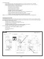 9
9
-
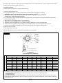 10
10
-
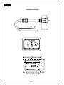 11
11
-
 12
12
-
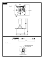 13
13
-
 14
14
-
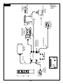 15
15
-
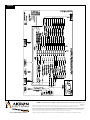 16
16
-
 17
17
-
 18
18
-
 19
19
-
 20
20
-
 21
21
-
 22
22
-
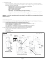 23
23
-
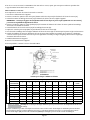 24
24
-
 25
25
-
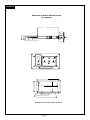 26
26
-
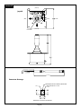 27
27
-
 28
28
-
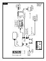 29
29
-
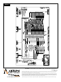 30
30
-
 31
31
-
 32
32
-
 33
33
-
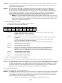 34
34
-
 35
35
-
 36
36
-
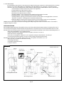 37
37
-
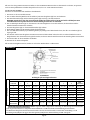 38
38
-
 39
39
-
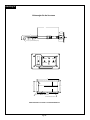 40
40
-
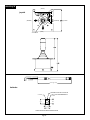 41
41
-
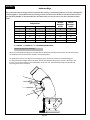 42
42
-
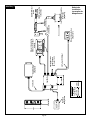 43
43
-
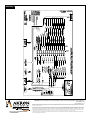 44
44
-
 45
45
-
 46
46
-
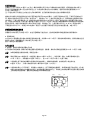 47
47
-
 48
48
-
 49
49
-
 50
50
-
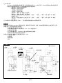 51
51
-
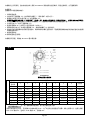 52
52
-
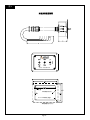 53
53
-
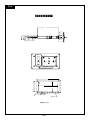 54
54
-
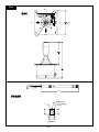 55
55
-
 56
56
-
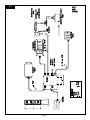 57
57
-
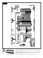 58
58
-
 59
59
-
 60
60
-
 61
61
-
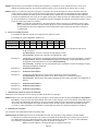 62
62
-
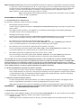 63
63
-
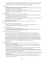 64
64
-
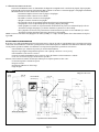 65
65
-
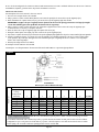 66
66
-
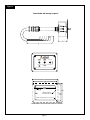 67
67
-
 68
68
-
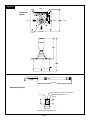 69
69
-
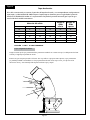 70
70
-
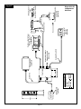 71
71
-
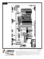 72
72


Akron 3578 STREAMMASTER Installation, Operating And Maintenance Instructions
- Tipo
- Installation, Operating And Maintenance Instructions
En otros idiomas
- français: Akron 3578 STREAMMASTER
- English: Akron 3578 STREAMMASTER
- Deutsch: Akron 3578 STREAMMASTER
Otros documentos
-
Land Rover L322 Range Rover Workshop Manual
-
 Kreg ACS Manual de usuario
-
Human Touch HT-9200 Manual de usuario
-
Lincoln 2008 Navigator Manual de usuario
-
Ford 2008 Explorer Sport Trac Manual de usuario
-
Allmand PORTABLE LIGHT TOWER, NIGHT-LITE E-SERIES (MANUAL WINCH) Manual de usuario
-
Sharper Image Human Touch Zero Gravity® 5.0 Massage Chair El manual del propietario
-
Bush Hog RMB Boom Mower El manual del propietario
-
-
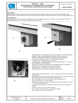 Duerkopp Adler 510 Manual de usuario

