Sanus F215 Manual de usuario
- Categoría
- Soportes de pared para panel plano
- Tipo
- Manual de usuario

Our US-based
install experts
are standing
by to help.
Call us at:
888-333-9952
Or, chat at:
SANUS.com/chatSV
Get it right the
first time.
HeightFinder™
shows you
where to drill.
Check it out at:
SANUS.com/1171
Want to watch
a video that
shows how
easy this DIY
project will be?
Watch it now at:
SANUS.com/2773
Recommended placement
WE’RE HERE TO HELP
F
215
INSTRUCTION MANUAL
Para Español ver página 22
BONUS!
+
Two 10"
Cable
Tunnels
4K HDMI
Cable

2
IMPORTANT SAFETY INSTRUCTIONS – SAVE THESE INSTRUCTIONS – PLEASE READ ENTIRE MANUAL PRIOR TO USE
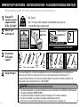
Before getting started, let’s make sure this mount is perfect for you!
No
—
Perfect!
Yes
—
This mount is NOT compatible. Visit MountFinder.sanus.com or call
1-888-333-9952 to find a compatible mount.
Do you have
all the tools
needed?
1
2
3
4
What is your
wall made of?
50 lbs.
(22.6 kg)
Ready to begin?
Does your TV
(including accessories)
weigh more than
50 lbs. (22.6 kg)?
Drywall with
wood studs?
Solid concrete or
concrete block?
Perfect!
Wood Stud Install
Concrete Install
Awl
Pencil Level
Stud Finder
Screwdriver
Tape
Measure
7/32 in.
(5.5 mm)
Wood
Drill Bit
Electric
Drill
Hammer
1/2 in.
(13 mm)
Socket
Wrench Drill Bit
3/8 in.
(10 mm)
Concrete
Unsure?
Call Customer Service: 1-888-333-9952
Concrete kit CMK1 (not included)
CAUTION:
DO NOT
install into
drywall alone
Please read through these instructions completely to be sure you’re comfortable with this easy install process.
Also check your TV owner’s manual to see if there are any special requirements for mounting your TV.
If you do not understand these instructions or have doubts about the safety of the installation, assembly or use
of this product, contact Customer Service at 1-888-333-9952.
CAUTION: Avoid potential personal injury or property damage!
● This product is designed for use in wood stud, solid concrete, and concrete block walls - DO NOT install into drywall alone
● This product is designed for INDOOR USE ONLY
● The wall must be capable of supporting five times the weight of the TV and mount combined
● Do not use this product for any purpose not explicitly specified by manufacturer
● Manufacturer is not responsible for damage or injury caused by incorrect assembly or use

3
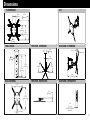
Dimensions
7.87in
200mm
3.94in
100mm
15.75in
400mm
11.81in
300mm
.34in
8.7mm
4.02in
102mm
.99in
25.2mm
45deg
45deg
5deg
15deg
15.0in
381mm
9.06in
230mm
8.27in
210mm
2.91in
74mm
.33in
8.4mm
3.1in
78mm
2.8in
71mm
WITHOUT EXTENSION
BRACKETS
17.07in
433.7mm
17.07in
433.7mm
6deg
TV INTERFACE
WALL PLATE
ROLL CONTROL
TOP VIEW - EXTENDED
TOP VIEW - RETRACTED
SIDE VIEW - EXTENDED
SIDE VIEW - RETRACTED
3-D
Before getting started, let’s make sure this mount is perfect for you!

4
M4 x 12mm
M6 x 12mm M6 x 35mm
M4 x 35mm
M6 x 20mm
M8 x 16mm
M8 x 12mm
M8 x 35mm
5/16 x 2¾ in.
2.5mm
22mm
M8 x 25mm M8 x 50mm
WELCOME! THANKS FOR
CHOOSING SANUS VUEPOINT.
THIS IS GOING TO BE EASY!
LET’S GET STARTED.
STEP 1
Attach TV brackets to back of TV.
STEP 2
Attach wall plate to wall using
provided hardware.
STEP 3
Hang TV on arm.
Our live, US-based install
experts are standing by to help.
Call us at:
Or, chat at:
Get it right the rst time!
HeightFinder
™
shows you
where to drill.
Use it now at:
Want to watch a video that
shows how easy this is?
Watch it now at:
M5 x 6mm
M
4
/
M
5
M
6
/
M
8
5/16 x 2¾ in.
Fischer UX10 x 60R Anchor
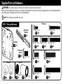
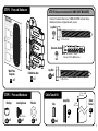
NOTE: Not all hardware included will be used.
WARNING: This product contains small items that could be a choking hazard if swallowed.
Before starting assembly, verify all parts are included and undamaged. If any parts are missing or damaged, do not return the damaged item to
your dealer; contact Customer Service. Never use damaged parts!
Supplied Parts and Hardware
STEP 1 Parts and Hardware
01
Faceplate
TV Screws
Washers Spacers
TV Bracket
Extender
TV Bracket
Screw
08
x4
09
x4
12
x4
11
x4
10
x4
13
x4
14
x4
16
x4
15
x4
04
x4
05
x4
06
x4
07
x4
03
x8
x1
02
x4

5
M4 x 12mm
M6 x 12mm M6 x 35mm
M4 x 35mm
M6 x 20mm
M8 x 16mm
M8 x 12mm
M8 x 35mm
5/16 x 2¾ in.
2.5mm
22mm
M8 x 25mm M8 x 50mm
WELCOME! THANKS FOR
CHOOSING SANUS VUEPOINT.
THIS IS GOING TO BE EASY!
LET’S GET STARTED.
STEP 1
Attach TV brackets to back of TV.
STEP 2
Attach wall plate to wall using
provided hardware.
STEP 3
Hang TV on arm.
Our live, US-based install
experts are standing by to help.
Call us at:
Or, chat at:
Get it right the rst time!
HeightFinder
™
shows you
where to drill.
Use it now at:
Want to watch a video that
shows how easy this is?
Watch it now at:
M5 x 6mm
M
4
/
M
5
M
6
/
M
8
5/16 x 2¾ in.
Fischer UX10 x 60R Anchor
STEP 2B: Concrete Installation Kit CMK1 [NOT INCLUDED]
STEP 2 Parts and Hardware
STEP 3 Parts and Hardware
Nut Cap
17
x1
18
x1
Full Motion Arm
Wall Plate
Template
Lag Bolt
Lag Bolt
Concrete Anchor
C1
x2
C2
x2
19
x2
21
x1
20
x1
22
x1
Washer
Clip
Long Clip
Cabel
Tunnel
Contact Customer Service at 1-888-333-9952 to have these
additional pieces shipped directly to you.
Locking Screw
Cable Tunnel Kit
x4
23
x1
24
x2
25
10 in.
(25.4 cm)
2.5 in.
(6.3 cm)

6
cm
inches
cm
inches
inch dimensions are approximate
inches cm mm
3 7.5 75
4 10 100
7 ⅞ 20 200
11 ¾ 30 300
15 ¾ 40 400
W
H
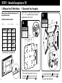
STEP 1 Attach Faceplate to TV
1.1 Measure Your TV Hole Pattern 1.2 Assemble Your Faceplate
Measure the width and height of your TV
hole pattern in mm.
Record your measurements:
Width_______mm x Height_______mm
Based on your TV hole pattern measurements
(W mm x H mm), determine your Faceplate
configuration: A, B, C, D or E.
A
200
[7 ⅞ in.]
200
[7 ⅞ in.]
400
[15¾ in.]
400
[15¾ in.]
B
These smaller hole patterns only use
Faceplate
01
. Do not use the four TV
brackets
02
and eight screws
03
.
02
100
[4 in.]
100
[4 in.]
03
Assemble TV brackets
02
onto Faceplate
01
and secure using eight screws
03
in
the corner holes indicated.
02
01
01
03
300
[11 ¾ in.]
300
[11 ¾ in.]
02
100 x 100
200 x 100
200 x 200
For TV Hole Pattern
Measurements
(Dimensions in mm)
300 x 300
400 x 400
For TV Hole Pattern
Measurements
(Dimensions in mm)

7
03
D E
03
200
[7 ⅞ in.]
200
[7 ⅞ in.]
01
Assemble TV brackets
02
onto Faceplate
01
and secure using eight screws
03
in
the corner holes indicated.
Assemble TV brackets
02
onto Faceplate
01
and secure using eight screws
03
in
the corner holes indicated.
01
02
02
02
02
C
03
Assemble TV brackets
02
onto Faceplate
01
and secure using eight screws
03
in
the corner holes indicated.
02
02
01
400
[15¾ in.]
400
[15 ¾ in.]
400
[15¾ in.]
300
[11 ¾ in.]
300
[11 ¾ in.]
300
[11 ¾ in.]
400 x 300
For TV Hole Pattern
Measurements
(Dimensions in mm)
300 x 200
400 x 200
For TV Hole Pattern
Measurements
(Dimensions in mm)
200 x 300
200 x 400
For TV Hole Pattern
Measurements
(Dimensions in mm)

8
Too Long
Too Short
Correct
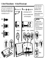
1.3 Select TV Screw Diameter
1.4 Select TV Screw Length
Standard configurations
are shown. For special
applications, or if you
are uncertain about your
hardware selection, contact
Customer Service.
CAUTION:
Verify adequate thread
engagement with your screw/
washer/spacer combination
AND TV bracket.
– Too short will not hold the TV.
– Too long will damage the TV.
M4
M6
M8
a
b
a
: For flat-back TVs,
no spacers
06
or
07
required.
b
: Spacers
06
or
07
supplied for:
● Round (irregular) back TVs
● Extra space needed (for cables
or inset mounting holes)
FLAT BACK ROUND BACK CABLES INSET HOLES
Test the four TV screw diameters (M4,
M6, and M8) in the threaded inserts on
the back of your TV to determine which
screw diameter fits your TV.
06 07

9
1.5 Attach TV Bracket
TV Bracket Configuration B
Illustrated (with spacers)
0406 0507
04 05
a: Flat Back
b: Round Back / Extra Space
TV Bracket Configuration A
Illustrated (with spacers)
Position your TV bracket configuration (A, B, C, D or E) onto your TV, making sure the bracket is both centered and level over your TV hole pattern.
NOTE: The hanging tab
H
on faceplate
01
must be oriented toward the top of the TV.
Secure the TV bracket using your selection: (a) screw/washer or (b) screw/washer/spacer.
CAUTION: Avoid potential personal injuries and property damage! DO NOT use power tools for this step. Tighten the screws only enough to
secure the TV bracket to the TV. DO NOT overtighten the screws.
H
01
16
16
08
08
01
01
02

10
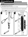
1. Locate your stud. Verify and mark the center of the stud by finding the stud edges using an awl, a thin nail, or an edge to edge stud finder.
2. Position the template
17
at your desired height and line up the holes with your stud center line. Level the template and tape in place.
WELCOME! THANKS FOR
CHOOSING SANUS VUEPOINT.
THIS IS GOING TO BE EASY!
LET’S GET STARTED.
STEP 1
Attach TV brackets to back of TV.
STEP 2
Attach wall plate to wall using
provided hardware.
STEP 3
Hang TV on arm.
Our live, US-based install
experts are standing by to help.
Call us at:
Or, chat at:
Get it right the rst time!
HeightFinder
™
shows you
where to drill.
Use it now at:
Want to watch a video that
shows how easy this is?
W
atch it now at:
WELCOME! THANKS FOR
CHOOSING SANUS VUEPOINT.
THIS IS GOING TO BE EASY!
LET’S GET STARTED.
STEP 1
Attach TV brackets to back of TV.
STEP 2
Attach wall plate to wall using
provided hardware.
STEP 3
Hang TV on arm.
Our live, US-based install
experts are standing by to help.
Call us at:
Or, chat at:
Get it right the rst time!
HeightFinder
™
shows you
where to drill.
Use it now at:
Want to watch a video that
shows how easy this is?
Watch it now at:
WELCOME! THANKS FOR
CHOOSING SANUS VUEPOINT.
THIS IS GOING TO BE EASY!
LET’S GET STARTED.
STEP 1
Attach TV brackets to back of TV.
STEP 2
Attach wall plate to wall using
provided hardware.
STEP 3
Hang TV on arm.
Our live, US-based install
experts are standing by to help.
Call us at:
Or, chat at:
Get it right the rst time!
HeightFinder
™
shows you
where to drill.
Use it now at:
Want to watch a video that
shows how easy this is?
W
atch it now at:
WELCOME! THANKS FOR
CHOOSING SANUS VUEPOINT.
THIS IS GOING TO BE EASY!
LET’S GET STARTED.
STEP 1
Attach TV brackets to back of TV.
STEP 2
Attach wall plate to wall using
provided hardware.
STEP 3
Hang TV on arm.
Our live, US-based install
experts are standing by to help.
Call us at:
Or, chat at:
Get it right the rst time!
HeightFinder
™
shows you
where to drill.
Use it now at:
Want to watch a video that
shows how easy this is?
Watch it now at:
≤ 5/8 in.
(16 mm)
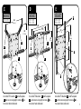
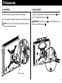
STEP 2A Attach Wall Plate to Wall
Wood Stud Installation
CAUTION: Avoid potential personal injury or property damage!
● Drywall covering the wall must not exceed 5/8 in. (16 mm)
● Minimum wood stud size: nominal 2 x 4 in. (51 x 102 mm) actual 1 ½ x 3 ½ in. (38 x 89 mm)
21
17

11
WELCOME! THANKS FOR
CHOOSING SANUS VUEPOINT.
THIS IS GOING TO BE EASY!
LET’S GET STARTED.
STEP 1
Attach TV brackets to back of TV.
STEP 2
Attach wall plate to wall using
provided hardware.
STEP 3
Hang TV on arm.
Our live, US-based install
experts are standing by to help.
Call us at:
Or, chat at:
Get it right the rst time!
HeightFinder
™
shows you
where to drill.
Use it now at:
Want to watch a video that
shows how easy this is?
W
atch it now at:
WELCOME! THANKS FOR
CHOOSING SANUS VUEPOINT.
THIS IS GOING TO BE EASY!
LET’S GET STARTED.
STEP 1
Attach TV brackets to back of TV.
STEP 2
Attach wall plate to wall using
provided hardware.
STEP 3
Hang TV on arm.
Our live, US-based install
experts are standing by to help.
Call us at:
Or, chat at:
Get it right the rst time!
HeightFinder
™
shows you
where to drill.
Use it now at:
Want to watch a video that
shows how easy this is?
Watch it now at:
WELCOME! THANKS FOR
CHOOSING SANUS VUEPOINT.
THIS IS GOING TO BE EASY!
LET’S GET STARTED.
STEP 1
Attach TV brackets to back of TV.
STEP 2
Attach wall plate to wall using
provided hardware.
STEP 3
Hang TV on arm.
Our live, US-based install
experts are standing by to help.
Call us at:
Or, chat at:
Get it right the rst time!
HeightFinder
™
shows you
where to drill.
Use it now at:
Want to watch a video that
shows how easy this is?
W
atch it now at:
WELCOME! THANKS FOR
CHOOSING SANUS VUEPOINT.
THIS IS GOING TO BE EASY!
LET’S GET STARTED.
STEP 1
Attach TV brackets to back of TV.
STEP 2
Attach wall plate to wall using
provided hardware.
STEP 3
Hang TV on arm.
Our live, US-based install
experts are standing by to help.
Call us at:
Or, chat at:
Get it right the rst time!
HeightFinder
™
shows you
where to drill.
Use it now at:
Want to watch a video that
shows how easy this is?
Watch it now at:
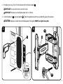
3. Drill pilot holes using a 7/32 in. (5.5 mm) diameter drill bit. Remove template
17
.
IMPORTANT: Be sure to drill into the center of the stud.
IMPORTANT: Pilot holes must be drilled to a depth of 2 ¾ in. (70 mm).
4. Install full motion arm
18
using two lag bolts
19
. Tighten the lag bolts only until they are pulled firmly against the wall plate.
CAUTION: Improper use could reduce the holding power of the lag bolt. DO NOT over-tighten the lag bolts.
Wood Stud Installation
7/32 in.
(5.5 mm)
2¾
in. (70 mm)
4
3
19
19
17
18

12
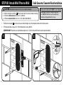
1. Position the template
17
on the wall at your desired height. Level the template and mark the hole locations.
2. Drill two pilot holes using a 3/8 in. (10 mm) diameter masonry drill bit.
IMPORTANT: Pilot holes must be drilled to a depth of 3 in. (75 mm). Never drill into the mortar between blocks.
WELCOME! THANKS FOR
CHOOSING SANUS VUEPOINT.
THIS IS GOING TO BE EASY!
LET’S GET STARTED.
STEP 1
Attach TV brackets to back of TV.
STEP 2
Attach wall plate to wall using
provided hardware.
STEP 3
Hang TV on arm.
Our live, US-based install
experts are standing by to help.
Call us at:
Or, chat at:
Get it right the rst time!
HeightFinder
™
shows you
where to drill.
Use it now at:
Want to watch a video that
shows how easy this is?
Watch it now at:
WELCOME! THANKS FOR
CHOOSING SA NUS VUEPOINT.
THIS IS GOING TO BE EASY!
LET’S GET STARTED.
STEP 1
Attach TV brackets to back of TV.
STEP 2
Attach wall plate to wall using
provided hardware.
STEP 3
Hang TV on arm.
Our live, US-based install
experts are standing by to help.
Call us at:
Or, chat at:
Get it right the rst time!
HeightFinder
™
shows you
where to drill.
Use it now at:
Want to watch a video that
shows how easy this is?
Watch it now at:
17
21
Concrete Installation Kit CMK1 is not included
(see page 5) Contact Customer Service
at 1-888-333-9952 to have the additional
hardware shipped directly to you.
STEP 2B Attach Wall Plate to Wall
Solid Concrete / Concrete Block Installation
3/8 in.
(10 mm)
3 in. (75 mm)
CAUTION: Avoid potential personal injury or property damage!
● Mount wall plate assembly
18
directly onto concrete surface (no wall covering)
● Minimum solid concrete thickness: 8 in. (203 mm)
● Minimum concrete block size: 8 x 8 x 16 in. (203 x 203 x 406 mm)
17

13
WELCOME! THANKS FOR
CHOOSING SANUS VUEPOINT.
THIS IS GOING TO BE EASY!
LET’S GET STARTED.
STEP 1
Attach TV brackets to back of TV.
STEP 2
Attach wall plate to wall using
provided hardware.
STEP 3
Hang TV on arm.
Our live, US-based install
experts are standing by to help.
Call us at:
Or, chat at:
Get it right the rst time!
HeightFinder
™
shows you
where to drill.
Use it now at:
Want to watch a video that
shows how easy this is?
Watch it now at:
WELCOME! THANKS FOR
CHOOSING SANUS VUEPOINT.
THIS IS GOING TO BE EASY!
LET’S GET STARTED.
STEP 1
Attach TV brackets to back of TV.
STEP 2
Attach wall plate to wall using
provided hardware.
STEP 3
Hang TV on arm.
Our live, US-based install
experts are standing by to help.
Call us at:
Or, chat at:
Get it right the rst time!
HeightFinder
™
shows you
where to drill.
Use it now at:
Want to watch a video that
shows how easy this is?
Watch it now at:
43
3. Remove the template
17
and insert two anchors
C2
(Fischer UX 10 x 60R - included in the Concrete Installation Kit CMK1*).
CAUTION: Be sure the anchors
C2
are seated flush with the concrete surface.
4. Install full motion arm
18
using two lag bolts
C1
. Tighten the lag bolts only until they are pulled firmly against the wall plate.
CAUTION: Improper use could reduce the holding power of the lag bolt. DO NOT over-tighten the lag bolts
C1
.
*
Contact Customer Service at 1-888-333-9952 to have the Concrete Installation Kit CMK1 shipped directly to you.
C2
C1
18

14
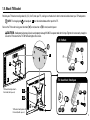
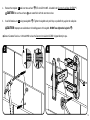
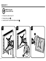
HEAVY! You may need assistance with this step.
STEP 3 Hang TV onto Wall Plate
1. Install the nut cap
20
on wall plate assembly
18
.
2. Fold first section of the arm of full motion arm
18
against the wall to provide stability.
1 2
18
18
20

15
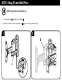
3 4
3. Hang the TV onto the arm of full motion arm
18
by first hooking the hanging tab
H
, then resting the TV into place.
4. Lock the TV to the full motion arm
18
with locking screw
21
and washer
22
.
IMPORTANT: This locking screw
21
must be installed to secure the TV onto the full motion arm
18
.
01
18
H
18
21
22
18
18
01

16
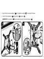
Manage Cables
Fully extend the arms before routing cables.
Route the cables through the channels on the top and bottom of the arm
18
for a cleaner look.
18

17
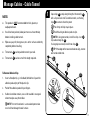
Manage Cables - Cable Tunnel
1
NOTES:
● This product is NOT recommended for brick, plaster, or
wallpapered walls.
● If wall has been painted, allow paint to cure at least 30 days
before installing cable tunnels.
● Wipe away any dirt, dust, grease, etc. on the surface and let dry
completely before installing.
● The tunnels
25
can be painted to match your wall.
● The tunnels
25
can be cut to fit the length required.
To Remove Adhesive Clips
1. Insert a flat object (e.g. - knife blade) behind the clip and the
adhesive pad and pry o the plastic clip.
2. Peel o the adhesive pad with your fingers.
3. If adhesive residue remains, use a cloth soaked in an organic
solvent to wipe away the residue.
NOTE: First test the solvent in a concealed spot to make
sure it will not damage the wall surface.
23
23
24
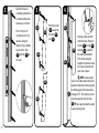
Space clips
23
evenly along the length of the tunnel(s)
25
with a clip near each end. To combine tunnels, use the long
clip
24
to connect where they meet.
A Press firmly until clips snap in place.
B Peel o backing of adhesive pads on clips.
NOTE: If using two tunnels, install five
clips - four
23
clips and one long clip
24
.
If using only one tunnel, install three
clips
23
.
TIP: If the edges of the two tunnels do not align, reverse
one tunnel end for end.
A
B

18
42 3
25
25
25
25
Arrange cables on either
side of the clips. Reattach
tunnels
25
to clips
23
and clip
24
, capturing
the cables behind them.
Press firmly along the
length of the tunnels where
the clips are located until
clips snap in place.
NOTE: Leave enough
slack in the cables above the tunnel
to prevent them from interfering with
or rubbing against the tunnel when
moving the TV. This could cause the
tunnel to separate from the clips.
TIP: Use tape the hold the cables
in place during install.
Carefully lift tunnel
assembly and position it
at the desired location
making sure it is level.
Press firmly for 10
seconds at each clip
location along the
length of the assembly
to secure the clips
23
and clip
24
to
the wall.
Peel the tunnels
25
away from
the clips
23
and
24
.
23
24
23
23
24

19
L
o
o
s
e
n
T
i
g
h
t
e
n
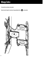
TV Adjustments
TILT ADJUSTMENT
Your TV should adjust easily when moved, then stay in place.
If your TV is too loose or too tight, adjust the tilt tension knob by hand.
NOTE: Once your TV is in place, tighten the tilt tension knob to
prevent unwanted movement.
LEVEL ADJUSTMENT
To adjust the leveling of your TV, loosen the locking screw
21
, level
your TV, then tighten locking screw
21
.
IMPORTANT: This locking screw
21
must be installed to secure
the TV onto the full motion arm
18
.
Tilt Tension Knob
21
18

20
18
HEAVY! You may need
assistance with this step.
1 2 3
REMOVING THE TV
1. Disconnect the cables from your TV.
2. Remove locking screw
21
.
3. Carefully lift your TV up and off of wall plate assembly
18
.
21

21

22
ESPAÑOL
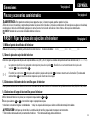
INSTRUCCIONES DE SEGURIDAD IMPORTANTES. CONSÉRVELAS. LEA TODO EL MANUAL ANTES DE UTILIZAR ESTE PRODUCTO.
Antes de comenzar, verifiquemos que este soporte sea el ideal para sus necesidades.
5,5 mm
(7/32'')
Madera
10 mm
(3/8'')
Hormigón
No
—
¡Perfecto!
Sí
—
Este soporte NO es compatible. Visite Mountfinder.Sanus.com o llame al 1-888-333-9952 para
encontrar un soporte compatible.
¿Su televisor pesa
más de 22.6 kg
(50 libras), incluidos
los accesorios?
Lea estas instrucciones en su totalidad para estar seguro de sentirse cómodo con este fácil proceso de instalación. Consulte
también el manual del usuario de su televisor para ver si existe algún requisito especial para instalar su televisor en la pared.
Si no entiende las instrucciones o si tiene dudas acerca de la seguridad de la instalación, del ensamblado o del uso del
producto, póngase en contacto con el servicio de atención al cliente al 1-888-333-9952.
¿Tiene
todas las
herramientas
necesarias?
1
2
3
4
¿De qué está
hecha su pared?
22.6 kg
(50 lb)
¿Listo para
comenzar?
13 mm
(1/2”)
¿Tabiques
de yeso con
montantes de
madera?
¡Perfecto!
DestornilladorCinta métrica Broca Broca
Taladro
eléctrico MartilloLlave de tubo PunzónLápiz Nivel
Localizador
de montantes
PRECAUCIÓN:
NO lo instale
en tabiques
únicamente
de yeso
Paredes con
montantes de madera
paredes con de
hormigón
¿Hormigón sólido
o bloques de
cemento?
Llame al 1-888-333-9952
Concrete kit CMK1 (not included)
¿No está
seguro?
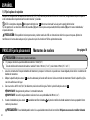
PRECAUCIÓN: Evite posibles lesiones personales y daños materiales.
● Este producto incluye instrucciones y elementos de sujeción para su instalación en paredes con montantes de madera,
en superficies de hormigón y sobre bloques de cemento. NO lo instale en tabiques únicamente de yeso.
● Este producto está diseñado para USO EN EL INTERIOR SOLAMENTE
● La pared debe soportar cinco veces el peso del televisor y del soporte juntos.
● No utilice este producto para ningún otro propósito que no sea el explícitamente especificado por el fabricante.
● El fabricante no se responsabiliza por ningún daño o lesión resultante del montaje incorrecto o de uso indebido.

23
NOTA: No todos los accesorios incluidos deberán utilizarse.
ADVERTENCIA: Este producto contiene piezas pequeñas que, si fuesen tragadas, podrían producir asfixia.
Antes de iniciar el ensamblaje, compruebe que todas las piezas estén incluidas y en buenas condiciones. Si faltan piezas o alguna está dañada,
no devuelva el artículo al distribuidor; póngase en contacto con el servicio de atención al cliente. Nunca utilice piezas deterioradas.
Piezas y accesorios suministrados
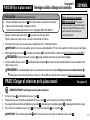
PASO 1 Fijar la placa de sujeción al televisor
1,1 Mida el patrón de orificios del televisor
1,2 Arme la placa de sujeción del televisor
Determine qué configuración de placa de sujeción debe usar (A, B, C, D o E) según las medidas del patrón de orificios del televisor (W mm x H mm).
Los patrones de orificios más pequeños solo requieren placa de sujeción
01
. No utilice las cuatro extensiones de la placa de
sujeción
02
ni los ocho tornillos
03
.
Ensamble las extensiones
02
de la placa de sujeción y la placa de sujeción
01
tal como se muestra en la ilustración. Fije colocando
ocho tornillos
03
en los orificios de las esquinas que se muestran en la imagen.
A
B–E
Mida en mm el ancho y el alto del patrón de orificios del televisor. Anote las medidas: Ancho________mm x Alto________mm
ESPAÑOL
Ver página 4
Ver página 6
Dimensiones
Ver página 3
1,3 Seleccione el diámetro de los tornillos para el televisor
Enrosque manualmente los tornillos en los encastres roscados del dorso del televisor a fin de determinar qué diámetro de tornillos (M4, M6 o M8) utilizar.
1,4 Seleccione el largo de los tornillos para el televisor
a: Si el dorso del televisor es plano, no se requieren espaciadores
06
o
07
.
b: Los espaciadores
06
o
07
y los tornillos largos se proporcionan para:
• televisores con dorso irregular o redondeado • dejar un espacio adicional para cables o orificios de montaje intercalados
PRECAUCIÓN: Verifique que el tornillo o la combinación de tornillo y espaciador enrosquen correctamente.
– Si el tornillo es demasiado corto, no sostendrá el televisor. – Si es demasiado largo, dañará el televisor.

24
PRECAUCIÓN: Evite lesiones y daños materiales.
● El yeso que recubre la pared no debe exceder los 16 mm (5/8'')
● Tamaño mínimo del montante de madera: nominal 51 mm x 102 mm (2'' x 4''); real 38 mm x 89 mm (1½'' x 3½'')
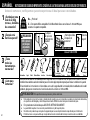
1. Localice un montante. Busque los bordes del montante y marque el centro con un punzón o un clavo delgado, o bien utilice un detector de
bordes de montantes.
2. Ubique la plantilla de placa mural
17
a la altura deseada y alinee los orificios con la línea central de los montantes. Nivele la plantilla y fíjela
con cinta adhesiva en el lugar.
3. Con una mecha de 5.5 mm (7/32'') de diámetro, realice los orificios guía. Retire la plantilla de placa mural
17
.
IMPORTANTE: Asegúrese de perforar el centro del montante.
IMPORTANTE: Los orificios guía deben realizarse hasta una profundidad de 70 mm (2 ¾ '').
4. Instale el módulo de la placa mural
18
usando dos tornillos tirafondo
19
. Ajuste los tornillos tirafondo solamente hasta que queden firmes
contra la placa mural.
PRECAUCIÓN: El uso indebido podría reducir la capacidad de retención de los tornillos. NO ajuste en exceso los tornillos tirafondo.
1,5 Fije la placa de sujeción
Coloque su configuración de soporte de televisor (A, B, C, D o E) sobre el patrón de orificios de su televisor, asegurándose de que el soporte
esté centrado sobre el patrón de orificios del televisor y nivelado.
NOTA: La lengüeta colgante
H
del soporte del televisor
01
debe estar orientada hacia la parte superior del televisor.
Fije el soporte con su selección de tornillo/arandela (a) parte trasera plana o espaciador/tornillo/arandela (b) parte trasera redondeada /
espacio adicional.
PRECAUCIÓN: Evite posibles lesiones personales y daños materiales. NO use herramientas eléctricas para este paso. Apriete los
tornillos con la fuerza adecuada para fijar la placa de sujeción al televisor. NO los apriete demasiado.
ESPAÑOL
PASO 2A Fijar la placa mural
Montantes de madera
Ver página 10

25
PRECAUCIÓN: Evite lesiones y daños materiales.
● Instale el módulo de la placa mural
18
directamente sobre la superficie de hormigón
● Espesor mínimo del hormigón: 8 pulgadas (203 mm)
● Tamaño mínimo del bloque de cemento: 8 x 8 x 16 pulgadas (203 x 203 x 406 mm)
1. Coloque la plantilla de la placa mural
17
en la pared a la altura que desee.
Nivele la plantilla de la placa mural y marque la ubicación de los orificios.
2. Realice los orificios guía con una mecha para mampostería de 3/8’’ (10 mm) de diámetro.
IMPORTANTE: Los orificios guía deben realizarse hasta una profundidad de 3’’ (75 mm). Nunca perfore el cemento que une los bloques.
3. Retire la plantilla de la placa mural
17
e introduzca dos anclajes
C2
(Fischer UX 10 x 60R - incluidos en el Kit de instalación en hormigón CMK1*).
PRECAUCIÓN: Cerciórese de que los anclajes
C2
queden nivelados respecto de la superficie de hormigón.
4. Instale el módulo de la placa mural
18
usando dos tornillos tirafondo
C1
. Ajuste los tornillos tirafondo solamente hasta que queden firmes
contra la placa mural.
PRECAUCIÓN: El uso indebido podría reducir la capacidad de retención de los tornillos. NO ajuste en exceso los tornillos tirafondo
C1
.
*
Comuníquese con el servicio de atención al cliente al 1-888-333-9952 para solicitar que le enviemos el Kit de instalación en hormigón.
El Kit de instalación en hormigón
CMK1 no está incluido (Ver página 5)
Comuníquese con el servicio de atención
al cliente al 1-888-333-9952 para solicitar
que le enviemos los elementos de
sujeción adicionales.
ESPAÑOL
PASO 2B Fijar la placa mural
Hormigón sólido o bloques de cemento
Ver página 12
¡ELEMENTO PESADO! Es posible que necesite ayuda en este paso.
PASO 3 Colgar el televisor en la placa mural
1. Instale la la tapa
20
en del módulo de la placa mural
18
.
2. Pliegue la primera sección del brazo del módulo de la placa mural
18
contra la pared para dar mayor estabilidad.
3. Para colgar el televisor en el brazo del módulo de la placa mural
18
, primero enganche la lengüeta colgante
H
y luego apoye el televisor en su lugar.
4. Fije el televisor al módulo de la placa mural
18
con el tornillo de seguridad
21
y la arandela
22
.
IMPORTANTE: Este tornillo de seguridad
21
debe instalarse para fijar el televisor al módulo de la placa mural
18
.
Ver página 14

26
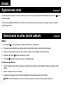
Organización de cables
Los cables pueden pasarse por los canales para cables que se encuentran en la parte superior del brazo del módulo de la placa mural
18
para un
aspecto más prolijo.
Pase los cables alrededor del poste del brazo y a través del área abierta del brazo, tal como se muestra en la imagen, para evitar aplastar los
cables al plegar el brazo.
ESPAÑOL
Ver página 16
NOTAS:
● Este producto NO está recomendado para paredes de ladrillo, de yeso o empapeladas.
● Si la pared ha sido pintada, deje secar la pintura durante al menos 30 días antes de instalar los túneles de cableado.
● Elimine la suciedad, el polvo, la grasa, etc. de la superficie y déjela secar por completo antes de la instalación.
● Puede pintar los túneles
25
para que coincidan con su pared.
● Los túneles
25
se pueden cortar para ajustarlos a la longitud requerida.
Para retirar los clips adhesivos
1. Inserte un objeto plano (por ejemplo, la hoja de un cuchillo) por detrás del tornillo y de las almohadillas adhesivas y destape el clip de
plástico.
2. Retire la almohadilla adhesiva con los dedos.
3. Si quedan restos de adhesivo, utilice un paño humedecido con un solvente orgánico para retirar los restos.
NOTA: Pruebe el solvente primero en una zona no visible para asegurarse de que no dañará la superficie de la pared.
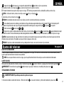
Administración de cables: túnel de cableado
Ver página 17

27
1 Separe los clips
23
de forma pareja a lo largo de la longitud del túnel
25
poniendo un clip en cada extremo.
Para combinar túneles, use el clip largo
24
para conectar los puntos en los que se encuentran.
A Presione firmemente hasta que los clips encajen en su lugar. B Retire la parte posterior de las almohadillas adhesivas de los clips.
NOTA: si utiliza dos túneles, instale cinco
clips o cuatro
23
clips y un clip largo
24
.
Si solo utiliza un túnel, instale tres
clips
23
.
TRUCO: Si los bordes de los dos túneles no se alinean, revertir un extremo del túnel para el extremo.
2
Con cuidado, levante el ensamblaje y posiciónelo en el lugar deseado asegurándose de que está nivelado. Presione firmemente por 10
segundos en la posición de cada clip a lo largo de la longitud del ensamblaje para asegurar los clips
23
y fijarlos
24
a la pared.
3
Retire los túneles
25
de los clips
23
y
24
.
4
Organice los cables a ambos lados de los clips. Vuelva a fijar los túneles
25
a los clips
23
e inmovilícelos
24
asegurándose de recoger
los cables tras ellos. Presione firmemente por toda la longitud de los túneles en donde los clips están ubicados, hasta que encajen en su lugar.
NOTA: Asegúrese de dejar el largo suficiente en los cables por encima del túnel para evitar que interfieran con el túnel o que rocen el túnel
cuando se mueva el televisor. Esto podría hacer que el túnel se separase de los clips.
TRUCO: Si sujeta los cables colocándolos encima y debajo de los túneles, será más fácil volver a fijar los túneles
ESPAÑOL
Ajustes del televisor
AJUSTE DE LA INCLINACIÓN
El televisor debe acomodarse fácilmente al moverlo, y luego quedar en su lugar. Si el televisor está demasiado suelto o demasiado ajustado,
ajuste la perilla de tensión de inclinación manualmente.
NOTA: Una vez que el televisor esté en su lugar, ajuste la perilla de tensión de inclinación para evitar movimientos indeseados.
AJUSTE DEL NIVEL
Para ajustar la nivelación de su televisor, afloje el tornillo de seguridad
21
, nivele el televisor, y luego ajuste el tornillo de seguridad
21
.
IMPORTANTE: Este tornillo de seguridad
21
debe instalarse para fijar el televisor al ensamblaje de la placa mural
18
.
EXTRACCIÓN DEL TELEVISOR
¡ELEMENTO PESADO! Es posible que necesite ayuda en este paso.
Ver página 19
1. Desconecte todos los cables del televisor. 2. Retire el tornillo
21
. 3. Levante el televisor y retírelo del módulo de la placa mural
18
.

Thank you for choosing SANUS Vuepoint! Please take a moment to let us know how we did:
Call us: 1-888-333-9952
6902-602032 00
Email us: [email protected]
Leave a review: vuepoint.sanus.com
Milestone AV Technologies and its aliated corporations and subsidiaries (collectively, “Milestone”), intend to make this manual accurate and complete.
However, Milestone makes no claim that the information contained herein covers all details, conditions, or variations. Nor does it provide for every possible
contingency in connection with the installation or use of this product. The information contained in this document is subject to change without notice or
obligation of any kind. Milestone makes no representation of warranty, expressed or implied, regarding the information contained herein. Milestone assumes
no responsibility for accuracy, completeness or suciency of the information contained in this document.
©2018 Milestone AV Technologies. All rights reserved. SANUS VuePoint, HeightFinder and the VuePoint logo are trademarks of Milestone.
All other brand names or marks are used for identification purposes and are trademarks of their respective owners.
Milestone Global Headquarters • 6436 City West Parkway • Eden Prairie, MN 55344 USA
-
 1
1
-
 2
2
-
 3
3
-
 4
4
-
 5
5
-
 6
6
-
 7
7
-
 8
8
-
 9
9
-
 10
10
-
 11
11
-
 12
12
-
 13
13
-
 14
14
-
 15
15
-
 16
16
-
 17
17
-
 18
18
-
 19
19
-
 20
20
-
 21
21
-
 22
22
-
 23
23
-
 24
24
-
 25
25
-
 26
26
-
 27
27
-
 28
28


Sanus F215 Manual de usuario
- Categoría
- Soportes de pared para panel plano
- Tipo
- Manual de usuario
En otros idiomas
- English: Sanus F215 User manual
Documentos relacionados
-
Sanus Simplicity SLF226 Manual de usuario
-
-
-
-
-
-
-
-
-

