
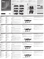
VE883 Package Contents
1 VE883T 4K HDMI Optical Transmitter
1 VE883R 4K HDMI Optical Receiver
2 Power Adapters
2 Terminal Block 3 Pole
2 Terminal Block 5 Pole
1 IR Receiver
B
Installation
9
(Optional) Connect an IR Transmitter/Receiver to the IR port on either
the VE883T or VE883R, depending on which device you wish to
control remotely.
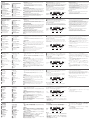
RS-232 Channel Transmission
The RS-232 signal transmission fl ow is illustrated below: From a source
device, the RS-232 signal is transmitted (Tx) to the VE883T receiving (Rx)
unit; the VE883R transmits (Tx) signals to the display device (Rx).
PIN
CONFIGURATION
(Captive screw
connectors)
Tx
Rx
Gnd
Tx
Rx
Gnd
Tx
Rx
Gnd
Tx
Rx
Gnd
Serial
Device
Fiber
Firmware Upgrades
1. Download the latest fi rmware package from the VE883 product page
at www.aten.com/download
2. From the downloaded package, execute the VE883.exe fi le. The
Firmware Upgrade Utility screen appears.
3. Read and agree to the License Agreement, and then click Next. The
utility automatically browses and lists the VE883 devices in Device List.
4. Click Next to start the upgrade. A confi rmation message, “Firmware
Upgrade: OK”, appears when the upgrade is complete.
Note:
1. The SFP modules can transmit signals up to 300 m (Black, VE883K1)
or 10 Km (Blue, VE883K2).
2. For supported resolutions, please refer to the VE883 User Manual.
A
Hardware Review
VE883T Front View
1
USB 2.0 Type-B
2
Audio In
3
RS-232 Port
4
HDMI In
VE883T Rear View
1
Optical Port
2
Ethernet Channel Port
3
IR Port
4
Firmware Upgrade Port
5
Power Jack
VE883T Top View
1
Link LED
2
Power LED
VE883R Front View
1
USB 2.0 Type-A
2
Audio Out
3
RS-232 Port
4
HDMI Out
VE883R Rear View
1
Optical Port
2
Ethernet Channel Port
3
IR Port
4
Firmware Upgrade Port
5
Power Jack
VE883R Top View
1
HDMI Out
2
Link LED
3
Power LED
Note:
• The Power LED lights green to indicate that the unit is receiving power.
• The Link LED lights orange to indicate that the fi ber is detected, and
communication between the transmitter and receiver is reliable.
B
Installation
1
Connect your video source to the HDMI In port on VE883T using an
HDMI cable.
2
Plug the SFP Modules to the Optical Ports on your VE883T and
VE883R, connect one end of the duplex fi ber optic cables to the
Optical Port on the VE883T, and the other end to the Optical Port on
the VE883R.
3
Use an HDMI cable to connect your video display to the HDMI Out
port on VE883R.
4
Plug the Power Adapter into the Power Jack.
5
(Optional) Connect your computer or control system to the RS-232
Port to perform serial commands.
6
(Optional) Connect a Cat 5e/6/6a cable to the Ethernet Channel Port.
7
(Optional) Connect a USB peripheral to the USB Type-A port.
8
(Optional) Connect the unit to an audio speaker.
Support and Documentation Notice
All information, documentation, fi rmware,
software utilities, and specifi cations
contained in this package are subject to
change without prior notifi cation by
the manufacturer.
To reduce the environmental impact of our
products, ATEN documentation and software
can be found online at
http://www.aten.com/download/
Technical Support
www.aten.com/support
이 기기는 업무용(A급) 전자파적합기기로서 판매자 또는
사용자는 이 점을 주의하시기 바라며, 가정외의 지역에
서 사용하는 것을 목적으로 합니다.
Scan for
more information
EMC Information
FEDERAL COMMUNICATIONS COMMISSION INTERFERENCE
STATEMENT:
This equipment has been tested and found to comply with the
limits for a Class A digital device, pursuant to Part 15 of the FCC
Rules. These limits are designed to provide reasonable protection
against harmful interference when the equipment is operated in
a commercial environment. This equipment generates, uses, and
can radiate radio frequency energy and, if not installed and used
in accordance with the instruction manual, may cause harmful
interference to radio communications. Operation of this equipment
in a residential area is likely to cause harmful interference in which
case the user will be required to correct the interference at his own
expense.
FCC Caution: Any changes or modifi cations not expressly approved
by the party responsible for compliance could void the user's
authority to operate this equipment.
Warning: Operation of this equipment in a residential environment
could cause radio interference.
This device complies with Part 15 of the FCC Rules. Operation is
subject to the following two conditions:(1) this device may not cause
harmful interference, and(2) this device must accept any interference
received, including interference that may cause undesired operation.
© Copyright 2020 ATEN
®
International Co., Ltd.
ATEN and the ATEN logo are trademarks of ATEN International Co., Ltd. All rights reserved. All
other trademarks are the property of their respective owners.
This product is RoHS compliant.
Part No. PAPE-1223-J30G Printing Date: 03/2020
4K HDMI Optical Extender
Quick Start Guide
VE883
ATEN VanCryst
™
1 2 3 4
1 2 3 54
1 2 3 4
1 2 3 54
1 2 1 2 3
VE883T Front View VE883R Front View
VE883T Rear View VE883R Rear View
VE883T Top View VE883R Top View
IR Port
IR Port
Serial Device
HDMI Display
VE883R
VE883T
6
7
8
5
3
4
4
9
9
1
2
Audio Speaker
USB Peripherals
HUB
Internet/
LAN
HDMI Source
1 IR Emitter
1 USB Cable
2 HDMI LockPro
2 SFP Modules
1 User Instructions
VE883T Package Contents
1 VE883T 4K HDMI Optical Transmitter
1 Power Adapter
1 Terminal Block 3 Pole
1 Terminal Block 5 Pole
1 IR Receiver
1 IR Emitter
1 USB Cable
1 HDMI LockPro
1 SFP Module
1 User Instructions
VE883R Package Contents
1 VE883R 4K HDMI Optical Receiver
1 Power Adapter
1 Terminal Block 3 Pole
1 Terminal Block 5 Pole
1 IR Receiver
1 IR Emitter
1 HDMI LockPro
1 SFP Module
1 User Instructions
9
(Opzionale) Collegare un trasmettitore/ricevitore IR alla porta IR su
VE883T o VE883R, a seconda del dispositivo da controllare in remoto.
Trasmissione canale RS-232
Il fl usso di trasmissione del segnale RS-232 è illustrato di seguito: Da un
dispositivo di origine, il segnale RS-232 viene trasmesso (Tx) all'unità di
ricezione VE883T (Rx) ; il VE883R trasmette segnali (Tx) al dispositivo di
visualizzazione (Rx).
CONFIGURAZIONE
PIN (connettori
prigionieri a vite)
Dispositivo
seriale
Tx Tx Tx Tx
Rx Rx Rx Rx
Gnd Gnd Gnd Gnd
Fibra
Aggionramenti del fi rmware
1. Scaricare l'ultimo pacchetto fi rmware dalla pagina del prodotto VE883
all'indirizzo www.aten.com/download
2. Dal pacchetto scaricato, eseguire il fi le VE883.exe. Viene visualizzata
la schermata Firmware Upgrade Utility.
3. Leggere il contratto di licenza e accettarne in termini, e quindi fare
clic su Avanti. L' utilità naviga automaticamente ed elenca i dispositivi
VE883 nell' elenco dispositivi.
4. Fare clic su Avanti per avviare l’aggiornamento. Un messaggio di
conferma, "Aggiornamento del fi rmware: OK", appare al termine dell'
aggiornamento.
Nota:
1. I moduli SFP possono trasmettere segnali fi no a 300 m (nero,
VE883K1) o 10 km (blu, VE883K2).
2. Per le risoluzioni supportate, fare riferimento al manuale utente
VE883.
A
Revisione Hardware
VE883T Vista frontale
1
USB 2.0 Tipo B
2
Audio In
3
Porta RS-232
4
HDMI In
VE883T Vista dal retro
1
Porta ottica
2
Porta canale Ethernet
3
Porta IR
4
Porta aggiornamento Firmware
5
Connettore d'alimentazione
VE883T Vista dall’alto
1
Link LED
2
LED accensione
VE883R Vista frontale
1
USB 2.0 Tipo A
2
Audio Out
3
Porta RS-232
4
HDMI Out
VE883R Vista dal retro
1
Porta ottica
2
Porta canale Ethernet
3
Porta IR
4
Porta aggiornamento Firmware
5
Connettore d'alimentazione
VE883R Vista dall’alto
1
HDMI Out
2
Link LED
3
LED alimentazione
Nota:
• Il LED di alimentazione lampeggia in verde per indicare che l'unità
riceve alimentazione.
• Il LED Link lampeggia in arancione per indicare che la fi bra viene rilevata
e la comunicazione tra il trasmettitore e il ricevitore è affi dabile.
B
Installazione
1
Collegare la sorgente video alla porta HDMI In su VE883T utilizzando
un cavo HDMI.
2
Collegare i moduli SFP alle porte ottiche del VE883T e del VE883R,
collegare un' estremità dei cavi in fi bra ottica duplex alla porta ottica
del VE883T e l' altra estremità alla porta ottica del VE883R.
3
Utilizzare un cavo HDMI per collegare il display video alla porta di
uscita HDMI su VE883R.
4
Collegare l' adattatore di alimentazione alla presa di alimentazione.
5
(Opzionale) Collegare il computer o il sistema di controllo alla porta
RS-232 per eseguire comandi seriali.
6
(Opzionale) Collegare un cavo Cat 5e/6/6a alla porta canale Ethernet.
7
(Opzionale) Collegare una periferica USB alla porta USB Tipo A.
8
(Opzionale) Collegare l'unità a un diffusore audio.
VE883K1 / VE883K2 4K HDMI Extender ottico
www.aten.com
9
(Opcional) Conecte un transmisor/receptor de IR al puerto IR del
VE883T o del VE883R, dependiendo del dispositivo que desee
controlar de forma remota.
Transmisión de canales RS-232
A continuación se ilustra el fl ujo de transmisión de la señal RS-232:
Desde un dispositivo fuente, la señal RS-232 se transmite (Tx) a la unidad
receptora VE883T (Rx); el VE883R transmite señales (Tx) al dispositivo de
visualización (Rx).
CONFIGURACIÓN
DE PINES
(conectores con
tornillo prisionero)
Dispositivo
serie
Tx Tx Tx Tx
Rx Rx Rx Rx
Gnd Gnd Gnd Gnd
Fibra
Actualizaciones del fi rmware
1. Descargue el último paquete de fi rmware de la página del producto
VE883 en www.aten.com/download
2. Desde el paquete descargado, ejecute el archivo VE883.exe.
Aparecerá la pantalla Firmware Upgrade Utility.
3. Lea y acepte el Acuerdo de licencia y a continuación haga clic en
Siguiente. La utilidad explora automáticamente y enumera los
dispositivos VE883 en la Lista de dispositivos.
4. Haga clic en Siguiente para iniciar la actualización. El mensaje
de confi rmación, “Firmware Upgrade: OK”, aparecerá cuando la
actualización se haya completado.
Nota:
1. Los módulos SFP pueden transmitir señales de hasta 300m (Negro,
VE883K1) o 10Km (Azul, VE883K2).
2. Para las resoluciones compatibles, consulte el Manual del usuario del
VE883.
A
Revisión del
hardware
Vista frontal del VE883T
1
USB 2.0 tipo B
2
Entrada de audio
3
Puerto RS-232
4
Entrada HDMI
Vista posterior del VE883T
1
Puerto óptico
2
Puerto del canal Ethernet
3
Puerto IR
4
Puerto de actualización del
fi rmware
5
Conector de alimentación
Vista superior del VE883T
1
LED de conexión
2
LED de alimentación
Vista frontal del VE883R
1
USB 2.0 tipo A
2
Salida de audio
3
Puerto RS-232
4
Salida HDMI
Vista posterior del VE883R
1
Puerto óptico
2
Puerto del canal Ethernet
3
Puerto IR
4
Puerto de actualización del
fi rmware
5
Conector de alimentación
Vista superior del VE883R
1
Salida HDMI
2
LED de conexión
3
LED de alimentación
Nota:
• El LED de alimentación se ilumina en verde para indicar que la unidad
está recibiendo alimentación.
• El LED Link (conexión) se ilumina en naranja para indicar que se detecta
la fi bra y que la comunicación entre el transmisor y el receptor es fi able.
B
Instalación
1
Conecte la fuente de vídeo al puerto de entrada HDMI del VE883T
con un cable HDMI.
2
Conecte los módulos SFP a los puertos ópticos del VE883T y VE883R,
conecte un extremo de los cables de fi bra óptica dúplex al puerto
óptico del VE883T y el otro extremo al puerto óptico del VE883R.
3
Utilice un cable HDMI para conectar la pantalla de vídeo al puerto de
salida HDMI del VE883R.
4
Conecte el adaptador de corriente a la toma de corriente.
5
(Opcional) Conecte su equipo o sistema de control al puerto RS-232
para ejecutar comandos en serie.
6
(Opcional) Conecte un cable Cat 5e/6/6a al puerto del canal Ethernet.
7
(Opcional) Conecte un periférico USB al puerto USB tipo A.
8
(Opcional) Conecte la unidad a un altavoz de audio.
Extensor óptico VE883K1 / VE883K2 4K HDMI
www.aten.com
7
(Optional) Schließen Sie ein USB-Peripheriegerät an den USB-Typ-A
Anschluss an.
8
(Optional) Schließen Sie das Gerät an einen Audio-Lautsprecher an.
9
(Optional) Schließen Sie einen IR-Sender/Empfänger an den IR-
Anschluss des VE883T oder VE883R an, je nachdem, welches Gerät
Sie fernsteuern möchten.
RS-232 Kanalübertragung
Der RS-232 Signalübertragungsfl uss ist unten abgebildet: Von einem
Quellgerät wird das RS-232-Signal (Tx) an die VE883T-Empfangseinheit
(Rx) übertragen; das VE883R sendet (Tx) Signale an das Anzeigegerät
(Rx).
PIN-
KONFIGURATION
(Kapselbare
Schraubklemmen)
Serielles
Gerät
Tx Tx Tx Tx
Rx Rx Rx Rx
Gnd Gnd Gnd Gnd
Faser
Firmware-Aktualisierungen
1. Laden Sie das neueste Firmware-Paket von der VE883-Produktseite
www.aten.com/download herunter
2. Führen Sie aus dem heruntergeladenen Paket die Datei VE883.exe
aus. Das Fenster Firmware-Aktualisierungsprogramm wird angezeigt.
3. Lesen Sie die Lizenzvereinbarung und stimmen Sie zu, und klicken
Sie dann auf Weiter. Das Dienstprogramm durchsucht und listet
automatisch die VE883 Geräte in der Geräteliste auf.
4. Klicken Sie auf Weiter, um die Aktualisierung zu starten. Eine
Bestätigungsmeldung,"Firmware-Aktualisierung: OK ", wird angezeigt,
wenn die Aktualisierung abgeschlossen ist.
Hinweis:
1. Die SFP-Module können Signale bis zu 300 m (Schwarz, VE883K1)
bzw. 10 Km (Blau, VE883K2) übertragen.
2. Die unterstützten Aufl ösungen entnehmen Sie bitte dem VE883
Benutzerhandbuch.
A
Hardware Übersicht
VE883T Vorderseite
1
USB 2.0 Typ-B
2
Audio-Eingang
3
RS-232 Anschluss
4
HDMI-Eingang
VE883T Rückseite
1
Optischer Anschluss
2
Ethernet-Kanalanschluss
3
IR-Anschluss
4
Anschluss für Firmware-
Aktualisierung
5
Netzbuchse
VE883T Oberseite
1
Link LED
2
Netz-LED
VE883R Frontansicht
1
USB 2.0 Typ-A
2
Audio-Ausgang
3
RS-232 Anschluss
4
HDMI-Ausgang
VE883R Rückseite
1
Optischer Anschluss
2
Ethernet-Kanalanschluss
3
IR-Anschluss
4
Anschluss für Firmware-
Aktualisierung
5
Netzbuchse
VE883R Oberseite
1
HDMI-Ausgang
2
Link LED
3
Netz LED
Hinweis:
• Die Netz-LED leuchtet grün, um anzuzeigen, dass das Gerät mit Strom
versorgt wird.
• Die Link-LED leuchtet orange, um anzuzeigen, dass die
Glasfaserverbindung erkannt wird, und die Kommunikation zwischen
Sender und Empfänger zuverlässig ist.
B
Installation
1
Verbinden Sie Ihre Videoquelle über ein HDMI-Kabel mit dem
HDMI-Eingang des VE883T.
2
Verbinden Sie die SFP-Module mit den optischen Anschlüssen Ihres
VE883T und VE883R, verbinden Sie ein Ende der Duplex-Lichtwellenleiter
mit dem optischen Anschluss des VE883T und das andere Ende mit dem
optischen Anschluss des VE883R.
3
Schließen Sie Ihren Videobildschirm mit einem HDMI-Kabel an den
HDMI-Ausgang des VE883R an.
4
Stecken Sie den Netzadapter in die Netzbuchse ein.
5
(Optional) Schließen Sie Ihren Computer oder Ihr Steuersystem an die
RS-232 Schnittstelle an, um serielle Befehle auszuführen.
6
(Optional) Schließen Sie ein Cat 5e/6/6a-Kabel an den
Ethernet-Kanalanschluss an.
VE883K1 / VE883K2 4K HDMI Optische Verlängerung
www.aten.com
9
(Facultatif) Connectez un émetteur/récepteur IR au port IR du VE883T ou
du VE883R, selon l'appareil que vous souhaitez contrôler à distance.
Transmission du canal RS-232
Le fl ux de transmission du signal RS-232 est illustré ci-dessous : À partir
d'un périphérique source, le signal RS-232 est transmis (Tx) à l'unité
de réception (Rx) VE883T ; le VE883R transmet (Tx) des signaux au
périphérique d'affi chage (Rx).
CONFIGURATION
DES BROCHES
(Connecteurs à
vis captives)
Périphérique
série
Tx Tx Tx Tx
Rx Rx Rx Rx
Gnd Gnd Gnd Gnd
Fibre
Mises à niveau du microprogramme
1. Téléchargez le dernier microprogramme depuis la page du VE883 à
www.aten.com/download
2. Dans le package téléchargé, exécutez le fi chier VE883.exe. L'écran de
l'utilitaire de mise à niveau du microprogramme apparaît.
3. Lisez et acceptez le contrat de licence, puis cliquez sur Suivant.
L'utilitaire parcourt et répertorie automatiquement les VE883 dans
Liste des périphériques.
4. Cliquez sur Suivant pour lancer la mise à niveau. Un message de
confi rmation, "Mise à niveau du microprogramme : OK " apparaît
lorsque la mise à niveau est terminée.
Remarque :
1. Les modules SFP peuvent transmettre des signaux jusqu'à 300 m (Noir,
VE883K1) ou 10 Km (Bleu, VE883K2).
2. Pour les résolutions prises en charge, reportez-vous au manuel
d'utilisation du VE883.
A
Présentation du
matériel
VE883T vue de face
1
USB 2.0 Type B
2
Entrée audio
3
Port RS-232
4
Entrée HDMI
VE883T vue de dos
1
Port optique
2
Port du canal Ethernet
3
Port IR
4
Port de mise à niveau du
microprogramme
5
Prise d'alimentation
VE883T vue de dessus
1
LED Link (Liaison)
2
LED d'alimentation
VE883R vue de face
1
USB 2.0 Type A
2
Sortie audio
3
Port RS-232
4
Sortie HDMI
VE883R vue de dos
1
Port optique
2
Port du canal Ethernet
3
Port IR
4
Port de mise à niveau du
microprogramme
5
Prise d'alimentation
VE883R vue de dessus
1
Sortie HDMI
2
LED Link (Liaison)
3
LED d'alimentation
Remarque :
• La LED d'alimentation s'allume en vert pour indiquer que l'appareil est
alimenté.
• La LED Link (Liaison) s'allume en orange pour indiquer que la fi bre est
détectée et que la communication entre l'émetteur et le récepteur est fi able.
B
Installation
1
Connectez votre source vidéo au port d'entrée HDMI du VE883T à
l'aide d'un câble HDMI.
2
Branchez les modules SFP aux ports optiques de votre VE883T et VE883R,
connectez une extrémité des câbles duplex en fi bre optique au port
optique du VE883T et l'autre extrémité du port optique au VE883R.
3
Utilisez un câble HDMI pour connecter votre affi chage vidéo au port
de sortie HDMI du VE883R.
4
Branchez l'adaptateur secteur à la prise d'alimentation.
5
(Facultatif) Connectez votre ordinateur ou votre système de contrôle
au port RS-232 pour effectuer des commandes en série.
6
(Facultatif) Connectez un câble Cat 5e/6/6a au port du canal Ethernet.
7
(Facultatif) Connectez un périphérique USB au port USB Type A.
8
(Facultatif) Connectez l'appareil à un haut-parleur audio.
Répéteur optique HDMI 4K VE883K1 / VE883K2
www.aten.com
A
Hardware Review
VE883K1 / VE883K2 4K HDMI Optical Extender
www.aten.com
La página se está cargando...
Transcripción de documentos
VE883 Package Contents A VE883T Package Contents 1 IR Emitter 1 USB Cable 2 HDMI LockPro 2 SFP Modules 1 User Instructions 1 VE883T 4K HDMI Optical Transmitter 1 VE883R 4K HDMI Optical Receiver 2 Power Adapters 2 Terminal Block 3 Pole 2 Terminal Block 5 Pole 1 IR Receiver VE883R Package Contents 1 USB Cable 1 HDMI LockPro 1 SFP Module 1 User Instructions 1 VE883T 4K HDMI Optical Transmitter 1 Power Adapter 1 Terminal Block 3 Pole 1 Terminal Block 5 Pole 1 IR Receiver 1 IR Emitter B Hardware Review VE883T Front View 1 HDMI LockPro 1 SFP Module 1 User Instructions 1 VE883R 4K HDMI Optical Receiver 1 Power Adapter 1 Terminal Block 3 Pole 1 Terminal Block 5 Pole 1 IR Receiver 1 IR Emitter Installation www.aten.com/support 8 Audio Speaker 7 Serial Device 5 ATEN VanCryst™ 2 3 4 VE883T Rear View 1 2 3 4 VE883R Rear View 2 3 4 VE883T Top View 5 1 2 3 3 4 EMC Information HUB 4 5 IR Port VE883R Top View VE883T 2 IR Port 9 9 4 © Copyright 2020 ATEN® International Co., Ltd. ATEN and the ATEN logo are trademarks of ATEN International Co., Ltd. All rights reserved. All other trademarks are the property of their respective owners. This product is RoHS compliant. Part No. PAPE-1223-J30G Scan for more information 6 VE883 1 HDMI Display USB Peripherals Internet/ LAN 4K HDMI Optical Extender Quick Start Guide All information, documentation, firmware, software utilities, and specifications contained in this package are subject to change without prior notification by the manufacturer. To reduce the environmental impact of our products, ATEN documentation and software can be found online at http://www.aten.com/download/ Technical Support VE883R Front View VE883R 1 Support and Documentation Notice 1 Printing Date: 03/2020 FEDERAL COMMUNICATIONS COMMISSION INTERFERENCE STATEMENT: This equipment has been tested and found to comply with the limits for a Class A digital device, pursuant to Part 15 of the FCC Rules. These limits are designed to provide reasonable protection against harmful interference when the equipment is operated in a commercial environment. This equipment generates, uses, and can radiate radio frequency energy and, if not installed and used in accordance with the instruction manual, may cause harmful interference to radio communications. Operation of this equipment in a residential area is likely to cause harmful interference in which case the user will be required to correct the interference at his own expense. FCC Caution: Any changes or modifications not expressly approved by the party responsible for compliance could void the user's authority to operate this equipment. Warning: Operation of this equipment in a residential environment could cause radio interference. This device complies with Part 15 of the FCC Rules. Operation is subject to the following two conditions:(1) this device may not cause harmful interference, and(2) this device must accept any interference received, including interference that may cause undesired operation. HDMI Source 1 2 이 기기는 업무용(A급) 전자파적합기기로서 판매자 또는 사용자는 이 점을 주의하시기 바라며, 가정외의 지역에 서 사용하는 것을 목적으로 합니다. 1 2 3 VE883K1 / VE883K2 4K HDMI Optical Extender A Hardware Review VE883T Front View USB 2.0 Type-B 2 Audio In 3 RS-232 Port 4 HDMI In 1 VE883T Rear View 1 2 3 4 5 Optical Port Ethernet Channel Port IR Port Firmware Upgrade Port Power Jack VE883T Top View Link LED 2 Power LED 1 VE883R Front View USB 2.0 Type-A Audio Out 3 RS-232 Port 4 HDMI Out 1 2 VE883R Rear View Optical Port Ethernet Channel Port 3 IR Port 4 Firmware Upgrade Port 5 Power Jack 1 www.aten.com Note: • The Power LED lights green to indicate that the unit is receiving power. • The Link LED lights orange to indicate that the fiber is detected, and communication between the transmitter and receiver is reliable. B 1 2 2 VE883R Top View HDMI Out 2 Link LED 3 Power LED 1 3 4 5 6 7 8 Installation Connect your video source to the HDMI In port on VE883T using an HDMI cable. Plug the SFP Modules to the Optical Ports on your VE883T and VE883R, connect one end of the duplex fiber optic cables to the Optical Port on the VE883T, and the other end to the Optical Port on the VE883R. Use an HDMI cable to connect your video display to the HDMI Out port on VE883R. Plug the Power Adapter into the Power Jack. (Optional) Connect your computer or control system to the RS-232 Port to perform serial commands. (Optional) Connect a Cat 5e/6/6a cable to the Ethernet Channel Port. (Optional) Connect a USB peripheral to the USB Type-A port. (Optional) Connect the unit to an audio speaker. 9 (Optional) Connect an IR Transmitter/Receiver to the IR port on either the VE883T or VE883R, depending on which device you wish to control remotely. RS-232 Channel Transmission The RS-232 signal transmission flow is illustrated below: From a source device, the RS-232 signal is transmitted (Tx) to the VE883T receiving (Rx) unit; the VE883R transmits (Tx) signals to the display device (Rx). Fiber Serial Device PIN CONFIGURATION (Captive screw connectors) Tx Tx Tx Tx Rx Rx Rx Rx Gnd Gnd Gnd Gnd Présentation du matériel VE883T vue de face USB 2.0 Type B 2 Entrée audio 3 Port RS-232 4 Entrée HDMI 1 VE883T vue de dos 1 2 3 4 5 Port optique Port du canal Ethernet Port IR Port de mise à niveau du microprogramme Prise d'alimentation VE883T vue de dessus LED Link (Liaison) 2 LED d'alimentation 1 VE883R vue de face USB 2.0 Type A Sortie audio 3 Port RS-232 4 Sortie HDMI 1 2 VE883R vue de dos Port optique Port du canal Ethernet 3 Port IR 4 Port de mise à niveau du microprogramme 5 Prise d'alimentation 1 2 VE883R vue de dessus Sortie HDMI LED Link (Liaison) 3 LED d'alimentation 1 2 www.aten.com Remarque : • La LED d'alimentation s'allume en vert pour indiquer que l'appareil est alimenté. • La LED Link (Liaison) s'allume en orange pour indiquer que la fibre est détectée et que la communication entre l'émetteur et le récepteur est fiable. B 1 2 3 4 5 6 7 8 Installation Connectez votre source vidéo au port d'entrée HDMI du VE883T à l'aide d'un câble HDMI. Branchez les modules SFP aux ports optiques de votre VE883T et VE883R, connectez une extrémité des câbles duplex en fibre optique au port optique du VE883T et l'autre extrémité du port optique au VE883R. Utilisez un câble HDMI pour connecter votre affichage vidéo au port de sortie HDMI du VE883R. Branchez l'adaptateur secteur à la prise d'alimentation. (Facultatif) Connectez votre ordinateur ou votre système de contrôle au port RS-232 pour effectuer des commandes en série. (Facultatif) Connectez un câble Cat 5e/6/6a au port du canal Ethernet. (Facultatif) Connectez un périphérique USB au port USB Type A. (Facultatif) Connectez l'appareil à un haut-parleur audio. 9 (Facultatif) Connectez un émetteur/récepteur IR au port IR du VE883T ou du VE883R, selon l'appareil que vous souhaitez contrôler à distance. Transmission du canal RS-232 Le flux de transmission du signal RS-232 est illustré ci-dessous : À partir d'un périphérique source, le signal RS-232 est transmis (Tx) à l'unité de réception (Rx) VE883T ; le VE883R transmet (Tx) des signaux au périphérique d'affichage (Rx). Fibre CONFIGURATION DES BROCHES (Connecteurs à vis captives) Périphérique série Tx Tx Tx Tx Rx Rx Rx Rx Gnd Gnd Gnd Gnd Hardware Übersicht VE883T Vorderseite USB 2.0 Typ-B 2 Audio-Eingang 3 RS-232 Anschluss 4 HDMI-Eingang 1 VE883T Rückseite 1 2 3 4 5 Optischer Anschluss Ethernet-Kanalanschluss IR-Anschluss Anschluss für FirmwareAktualisierung Netzbuchse VE883T Oberseite Link LED 2 Netz-LED 1 VE883R Frontansicht USB 2.0 Typ-A Audio-Ausgang 3 RS-232 Anschluss 4 HDMI-Ausgang 1 2 VE883R Rückseite 1 2 3 4 5 Optischer Anschluss Ethernet-Kanalanschluss IR-Anschluss Anschluss für FirmwareAktualisierung Netzbuchse VE883R Oberseite HDMI-Ausgang Link LED 3 Netz LED 1 2 Revisión del hardware Vista frontal del VE883T USB 2.0 tipo B Entrada de audio 3 Puerto RS-232 4 Entrada HDMI 1 2 Vista posterior del VE883T 1 2 3 4 5 Puerto óptico Puerto del canal Ethernet Puerto IR Puerto de actualización del firmware Conector de alimentación Vista superior del VE883T LED de conexión 2 LED de alimentación 1 Vista frontal del VE883R USB 2.0 tipo A Salida de audio 3 Puerto RS-232 4 Salida HDMI 1 2 Vista posterior del VE883R Puerto óptico Puerto del canal Ethernet 3 Puerto IR 4 Puerto de actualización del firmware 5 Conector de alimentación 1 2 Vista superior del VE883R Salida HDMI LED de conexión 3 LED de alimentación 1 2 Hinweis: • Die Netz-LED leuchtet grün, um anzuzeigen, dass das Gerät mit Strom versorgt wird. • Die Link-LED leuchtet orange, um anzuzeigen, dass die Glasfaserverbindung erkannt wird, und die Kommunikation zwischen Sender und Empfänger zuverlässig ist. B 1 2 3 4 5 6 Installation Verbinden Sie Ihre Videoquelle über ein HDMI-Kabel mit dem HDMI-Eingang des VE883T. Verbinden Sie die SFP-Module mit den optischen Anschlüssen Ihres VE883T und VE883R, verbinden Sie ein Ende der Duplex-Lichtwellenleiter mit dem optischen Anschluss des VE883T und das andere Ende mit dem optischen Anschluss des VE883R. Schließen Sie Ihren Videobildschirm mit einem HDMI-Kabel an den HDMI-Ausgang des VE883R an. Stecken Sie den Netzadapter in die Netzbuchse ein. (Optional) Schließen Sie Ihren Computer oder Ihr Steuersystem an die RS-232 Schnittstelle an, um serielle Befehle auszuführen. (Optional) Schließen Sie ein Cat 5e/6/6a-Kabel an den Ethernet-Kanalanschluss an. (Optional) Schließen Sie ein USB-Peripheriegerät an den USB-Typ-A Anschluss an. 8 (Optional) Schließen Sie das Gerät an einen Audio-Lautsprecher an. 9 (Optional) Schließen Sie einen IR-Sender/Empfänger an den IRAnschluss des VE883T oder VE883R an, je nachdem, welches Gerät Sie fernsteuern möchten. 7 RS-232 Kanalübertragung Der RS-232 Signalübertragungsfluss ist unten abgebildet: Von einem Quellgerät wird das RS-232-Signal (Tx) an die VE883T-Empfangseinheit (Rx) übertragen; das VE883R sendet (Tx) Signale an das Anzeigegerät (Rx). Faser PINKONFIGURATION (Kapselbare Schraubklemmen) Serielles Gerät Tx Tx Tx Tx Rx Rx Rx Rx Gnd Gnd Gnd Gnd Revisione Hardware VE883T Vista frontale USB 2.0 Tipo B 2 Audio In 3 Porta RS-232 4 HDMI In 1 VE883T Vista dal retro 1 2 3 4 5 Porta ottica Porta canale Ethernet Porta IR Porta aggiornamento Firmware Connettore d'alimentazione VE883T Vista dall’alto Link LED 2 LED accensione 1 VE883R Vista frontale USB 2.0 Tipo A Audio Out 3 Porta RS-232 4 HDMI Out 1 2 VE883R Vista dal retro Porta ottica Porta canale Ethernet 3 Porta IR 4 Porta aggiornamento Firmware 5 Connettore d'alimentazione 1 2 VE883R Vista dall’alto HDMI Out 2 Link LED 3 LED alimentazione 1 Firmware-Aktualisierungen 1. Laden Sie das neueste Firmware-Paket von der VE883-Produktseite www.aten.com/download herunter 2. Führen Sie aus dem heruntergeladenen Paket die Datei VE883.exe aus. Das Fenster Firmware-Aktualisierungsprogramm wird angezeigt. 3. Lesen Sie die Lizenzvereinbarung und stimmen Sie zu, und klicken Sie dann auf Weiter. Das Dienstprogramm durchsucht und listet automatisch die VE883 Geräte in der Geräteliste auf. 4. Klicken Sie auf Weiter, um die Aktualisierung zu starten. Eine Bestätigungsmeldung,"Firmware-Aktualisierung: OK ", wird angezeigt, wenn die Aktualisierung abgeschlossen ist. Hinweis: 1. Die SFP-Module können Signale bis zu 300 m (Schwarz, VE883K1) bzw. 10 Km (Blau, VE883K2) übertragen. 2. Die unterstützten Auflösungen entnehmen Sie bitte dem VE883 Benutzerhandbuch. www.aten.com Nota: • El LED de alimentación se ilumina en verde para indicar que la unidad está recibiendo alimentación. • El LED Link (conexión) se ilumina en naranja para indicar que se detecta la fibra y que la comunicación entre el transmisor y el receptor es fiable. B 1 2 3 4 5 6 7 8 Instalación Conecte la fuente de vídeo al puerto de entrada HDMI del VE883T con un cable HDMI. Conecte los módulos SFP a los puertos ópticos del VE883T y VE883R, conecte un extremo de los cables de fibra óptica dúplex al puerto óptico del VE883T y el otro extremo al puerto óptico del VE883R. Utilice un cable HDMI para conectar la pantalla de vídeo al puerto de salida HDMI del VE883R. Conecte el adaptador de corriente a la toma de corriente. (Opcional) Conecte su equipo o sistema de control al puerto RS-232 para ejecutar comandos en serie. (Opcional) Conecte un cable Cat 5e/6/6a al puerto del canal Ethernet. (Opcional) Conecte un periférico USB al puerto USB tipo A. (Opcional) Conecte la unidad a un altavoz de audio. 9 (Opcional) Conecte un transmisor/receptor de IR al puerto IR del VE883T o del VE883R, dependiendo del dispositivo que desee controlar de forma remota. Transmisión de canales RS-232 A continuación se ilustra el flujo de transmisión de la señal RS-232: Desde un dispositivo fuente, la señal RS-232 se transmite (Tx) a la unidad receptora VE883T (Rx); el VE883R transmite señales (Tx) al dispositivo de visualización (Rx). Fibra CONFIGURACIÓN DE PINES (conectores con tornillo prisionero) Dispositivo serie Tx Tx Tx Tx Rx Rx Rx Rx Gnd Gnd Gnd Gnd 2. Desde el paquete descargado, ejecute el archivo VE883.exe. Aparecerá la pantalla Firmware Upgrade Utility. 3. Lea y acepte el Acuerdo de licencia y a continuación haga clic en Siguiente. La utilidad explora automáticamente y enumera los dispositivos VE883 en la Lista de dispositivos. 4. Haga clic en Siguiente para iniciar la actualización. El mensaje de confirmación, “Firmware Upgrade: OK”, aparecerá cuando la actualización se haya completado. Nota: 1. Los módulos SFP pueden transmitir señales de hasta 300m (Negro, VE883K1) o 10Km (Azul, VE883K2). 2. Para las resoluciones compatibles, consulte el Manual del usuario del VE883. Actualizaciones del firmware 1. Descargue el último paquete de firmware de la página del producto VE883 en www.aten.com/download VE883K1 / VE883K2 4K HDMI Extender ottico A Remarque : 1. Les modules SFP peuvent transmettre des signaux jusqu'à 300 m (Noir, VE883K1) ou 10 Km (Bleu, VE883K2). 2. Pour les résolutions prises en charge, reportez-vous au manuel d'utilisation du VE883. www.aten.com Extensor óptico VE883K1 / VE883K2 4K HDMI A 2. Dans le package téléchargé, exécutez le fichier VE883.exe. L'écran de l'utilitaire de mise à niveau du microprogramme apparaît. 3. Lisez et acceptez le contrat de licence, puis cliquez sur Suivant. L'utilitaire parcourt et répertorie automatiquement les VE883 dans Liste des périphériques. 4. Cliquez sur Suivant pour lancer la mise à niveau. Un message de confirmation, "Mise à niveau du microprogramme : OK " apparaît lorsque la mise à niveau est terminée. Mises à niveau du microprogramme 1. Téléchargez le dernier microprogramme depuis la page du VE883 à www.aten.com/download VE883K1 / VE883K2 4K HDMI Optische Verlängerung A Note: 1. The SFP modules can transmit signals up to 300 m (Black, VE883K1) or 10 Km (Blue, VE883K2). 2. For supported resolutions, please refer to the VE883 User Manual. Firmware Upgrades 1. Download the latest firmware package from the VE883 product page at www.aten.com/download Répéteur optique HDMI 4K VE883K1 / VE883K2 A 2. From the downloaded package, execute the VE883.exe file. The Firmware Upgrade Utility screen appears. 3. Read and agree to the License Agreement, and then click Next. The utility automatically browses and lists the VE883 devices in Device List. 4. Click Next to start the upgrade. A confirmation message, “Firmware Upgrade: OK”, appears when the upgrade is complete. www.aten.com Nota: • Il LED di alimentazione lampeggia in verde per indicare che l'unità riceve alimentazione. • Il LED Link lampeggia in arancione per indicare che la fibra viene rilevata e la comunicazione tra il trasmettitore e il ricevitore è affidabile. B 1 2 3 4 5 6 7 8 Installazione Collegare la sorgente video alla porta HDMI In su VE883T utilizzando un cavo HDMI. Collegare i moduli SFP alle porte ottiche del VE883T e del VE883R, collegare un' estremità dei cavi in fibra ottica duplex alla porta ottica del VE883T e l' altra estremità alla porta ottica del VE883R. Utilizzare un cavo HDMI per collegare il display video alla porta di uscita HDMI su VE883R. Collegare l' adattatore di alimentazione alla presa di alimentazione. (Opzionale) Collegare il computer o il sistema di controllo alla porta RS-232 per eseguire comandi seriali. (Opzionale) Collegare un cavo Cat 5e/6/6a alla porta canale Ethernet. (Opzionale) Collegare una periferica USB alla porta USB Tipo A. (Opzionale) Collegare l'unità a un diffusore audio. 9 (Opzionale) Collegare un trasmettitore/ricevitore IR alla porta IR su VE883T o VE883R, a seconda del dispositivo da controllare in remoto. Trasmissione canale RS-232 Il flusso di trasmissione del segnale RS-232 è illustrato di seguito: Da un dispositivo di origine, il segnale RS-232 viene trasmesso (Tx) all'unità di ricezione VE883T (Rx) ; il VE883R trasmette segnali (Tx) al dispositivo di visualizzazione (Rx). Fibra CONFIGURAZIONE PIN (connettori prigionieri a vite) Dispositivo seriale Tx Tx Tx Tx Rx Rx Rx Rx Gnd Gnd Gnd Gnd Aggionramenti del firmware 1. Scaricare l'ultimo pacchetto firmware dalla pagina del prodotto VE883 all'indirizzo www.aten.com/download 2. Dal pacchetto scaricato, eseguire il file VE883.exe. Viene visualizzata la schermata Firmware Upgrade Utility. 3. Leggere il contratto di licenza e accettarne in termini, e quindi fare clic su Avanti. L' utilità naviga automaticamente ed elenca i dispositivi VE883 nell' elenco dispositivi. 4. Fare clic su Avanti per avviare l’aggiornamento. Un messaggio di conferma, "Aggiornamento del firmware: OK", appare al termine dell' aggiornamento. Nota: 1. I moduli SFP possono trasmettere segnali fino a 300 m (nero, VE883K1) o 10 km (blu, VE883K2). 2. Per le risoluzioni supportate, fare riferimento al manuale utente VE883.-
 1
1
-
 2
2


ATEN VE883T Guía de inicio rápido
- Tipo
- Guía de inicio rápido
en otros idiomas
- français: ATEN VE883T Guide de démarrage rapide
- italiano: ATEN VE883T Guida Rapida
- English: ATEN VE883T Quick start guide
- Deutsch: ATEN VE883T Schnellstartanleitung
- русский: ATEN VE883T Инструкция по началу работы
- português: ATEN VE883T Guia rápido
- 日本語: ATEN VE883T クイックスタートガイド
Artículos relacionados
-
ATEN VE883K2-AT-U Technical Manual
-
-
-
ATEN VE882 Guía de inicio rápido
-
ATEN VS381B 3-Port True 4K HDMI Switch Guía de inicio rápido
-
ATEN CE820-AT-U Guía de inicio rápido
-
ATEN CE611-AT-U Guía de inicio rápido
-
ATEN KE8950 Guía de inicio rápido
-
ATEN US221A Guía de inicio rápido
-
ATEN VE1801AEUT Guía de inicio rápido