Pepperl+Fuchs MLV12-54-2563/49/124 Instrucciones de operación
- Tipo
- Instrucciones de operación

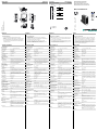
Abmessungen: Dimensions:
Construzione: Dimensiones:
alle Maße in mm
All dimensions are in mm
Tutte le dimensioni sono indicate in mm
Todas las dimensiones son en mm
Anschluss: Connection type:
Allacciamento elettrico: Conexión:
Deutsch English ItaliaEspañol
Sicherheitshinweise:
• Vor der Inbetriebnahme Betriebsanleitung lesen
• Anschluss, Montage und Einstellung nur durch Fachper-
sonal
• Kein Sicherheitsbauteil gemäß EU-Maschinenrichtlinie,
darf nicht für Personenschutz oder NOT-AUS-Funktion
verwendet werden.
Technical data
Technische Daten Dati tecniciDatos técnicos
Security Instructions:
• Read the operating instructions before attempting
commissioning
• Installation, connection and adjustments should only be
undertaken by specialist personnel
• No safety component in accordance with the EU
Machinery Directive. May not be used for protection of
personnel or EMERGENCY-STOP functions.
Avvertenze di sicurezza
• "Prima della messa in funzione, leggere le istruzioni per
l'uso.
• "Gli interventi di collegamento, montaggio e regolazione
devono essere effettuati solo da personale specializzato.
• "Non si tratta di un componente di sicurezza conforme
alla Direttiva UE "Macchine", pertanto non è consentito il
suo utilizzo per la protezione delle persone o per la
funzione di arresto d'emergenza.
Indicación de seguridad:
• Antes de la puesta en marcha leer las indicaciones de
uso.
• La conexión, el montaje y los ajustes deben realizarse
sólo por personal cualificado.
• No es ningún elemento de seguridad según las normas
CE que pueda utilizarse para protección de personas o
como función de paro de emergencia.
Option:
3
2
1
4
5
+UB
0 V
Q2
n.c.
Q1
/49
M12 x 1
15
10
M12 x 1
7.5
41.5
5.3
65
5.5
19.5
7
24
ø4.5
11.5
49
21.3
31.8
2
M4 / 4
Brandschutz-Reflexionslichtschranke
Fire protection retroreflective sensor
Barrera óptica de reflexión contra incendios
Barriera fotoelettrica a riflessione antincendio
MLV12-54-2563/49/124
Allgemeine Daten
Betriebsreichweite 0 ... 2,1 m (mit Reflektor H60)
Reflektorabstand 0,2 ... 2,1 m
Referenzobjekt Reflektor H60
Lichtsender LED 645 nm
Lichtart rot, Wechsellicht
Lichtfleckdurchmesser ca. 70 mm
Öffnungswinkel 1,5 °
Fremdlichtgrenze 50000 Lux
Anzeigen/Bedienele-
mente
Betriebsanzeige LED grün, blinkend im Kurzschlussfall
Funktionsanzeige 2 LEDs gelb, leuchten bei freiem Lichtstrahl,
blinken bei Unterschreiten der Funktionsres-
erve, aus bei Strahlunterbrechung.
Bedienelemente Drehschalter für hell/dunkel
Elektrische Daten
Betriebsspannung UB10 ... 30 V DC
Welligkeit max. 10 %
Leerlaufstrom I0max. 40 mA
Schutzklasse II, Bemessungsspannung
≤
300 V AC bei
Verschmutzungsgrad 1-2 nach IEC 60664-1
Ausgang
Schaltungsart hell-/dunkelschaltend umschaltbar
Signalausgang 1 NPN- und 1 PNP-Ausgang, gleichschaltend,
kurzschlussfest, verpolsicher, offener Kollek-
tor
Schaltspannung max. 30 V DC
Schaltstrom max. 0,2 A
Spannungsfall Ud
≤
2,5 V DC
Schaltfrequenz f
≤
40 Hz
Ansprechzeit 10 ms
Normenkonformität
Normen EN 60947-5-2
rauchunempfindlich bis 2 dB/m ( EN 54-12 )
Umgebungsbedingungen
Umgebungstemperatur -40 ... 60 °C (-40 ... 140 °F)
Lagertemperatur -40 ... 75 °C (-40 ... 167 °F)
Relative Luftfeuchtigkeit 30% ... 85% nicht kondensierend ; nicht ver-
eisend
Mechanische Daten
Schutzart IP67
Anschluss Steckeranschluss, 5-polig mit Metallgewinde
M12 x 1, drehbar 90°
Material
Gehäuse Rahmen: Zink-Druckguss, vernickelt
Seitenteile: Kunststoff PC, glasfaserverstärkt
Lichtaustritt Kunststoffscheibe
Masse 60 g
Zulassungen und Zertifi-
kate
UL-Zulassung cULus Listed, Class 2 Power Source, Type 1
enclosure
CCC-Zulassung Produkte, deren max. Betriebsspannung
≤
36
V ist, sind nicht zulassungspflichtig und daher
nicht mit einer CCC-Kennzeichnung verse-
hen.
Zulassungen VdS/DIBt Übereinstimmungszertifikat Nr.
25020
General specifications
Effective detection range 0 ... 2.1 m (with H60 reflector)
Reflector distance 0.2 ... 2.1 m
Reference target H60 reflector
Light source LED 645 nm
Light type modulated visible red light
Diameter of the light spot approx. 70 mm
Angle of divergence 1.5 °
Ambient light limit 50000 Lux
Indicators/operating
means
Operation indicator LED green, flashes in case of short-circuit
Function indicator 2 LEDs yellow, light up when light beam is
free, flash when falling short of the stability
control, off when light beam is interrupted
Control elements rotary switch for light/dark
Electrical specifications
Operating voltage UB10 ... 30 V DC
Ripple max. 10 %
No-load supply current I0max. 40 mA
Protection class II, rated voltage
≤
300 V AC with pollution
degree 1-2 according to IEC 60664-1
Output
Switching type light/dark on switchable
Signal output 1 NPN and 1 PNP output, direct switching,
short-circuit protected, reverse polarity protec-
ted, open collector
Switching voltage max. 30 V DC
Switching current max. 0.2 A
Voltage drop Ud
≤
2.5 V DC
Switching frequency f
≤
40 Hz
Response time 10 ms
Standard conformity
Standards EN 60947-5-2
smoke insensitive up to 2 dB/m ( EN 54-12 )
Ambient conditions
Ambient temperature -40 ... 60 °C (-40 ... 140 °F)
Storage temperature -40 ... 75 °C (-40 ... 167 °F)
Relative humidity 30% ... 85% non-condensing ; Non-icing
Mechanical specifications
Degree of protection IP67
Connection 5-pin M12 x 1 connector with metal thread,
90° rotatable
Material
Housing Frame: nickel plated, die cast zinc,
Laterals: glass-fiber reinforced plastic PC
Optical face Plastic pane
Mass 60 g
Approvals and certifica-
tes
UL approval cULus Listed, Class 2 Power Source, Type 1
enclosure
CCC approval CCC approval / marking not required for pro-
ducts rated
≤
36 V
Approvals VdS/DIBt certificate of compliance No. 25020
Dati generali
Distanza della portata 0 ... 2,1 m (con riflettore H60)
Distanza del riflettore 0,2 ... 2,1 m
Oggetto di riferimento Riflettore H60
Trasmettitore fotoelettrico LED 645 nm
Tipo di luce rossa modulata
Diametro spot circa. 70 mm
Angolo di apertura 1,5 °
Limite luce estranea 50000 Lux
Indicatori / Elementi di
comando
Visualizzatore di stato LED verde lampeggiante in caso di corto cir-
cuito
Visualizzatore funzioni 2 LED gialli, sono accesi a fascio luminoso
libero, lampeggerà alla diminuzione oltre la
riserva funzionale, spenti a fascio luminoso
interrotto.
Elementi di comando Interruttore rotante per presenza/assenza di
luce
Dati elettrici
Tensione di esercizio UB10 ... 30 V DC
Oscillazione max. 10 %
Corrente in assenza di carico
I0
max. 40 mA
Classe di protezione II, Tensione nominale
≤
300 V AC con grado
d'inquinamento 1-2 secondo IEC 60664-1
Uscita
Tipo di circuito Commutazione light on/dark on, invertibile
Uscita del segnale 1 uscita NPN e 1 uscita PNP, con commutazi-
one sincrona, a prova di corto circuito, pro-
tette contro le inversioni di polarità, collettore
aperto
Tensione di uscita max. 30 V DC
Corrente di uscita max. 0,2 A
Caduta di tensione Ud
≤
2,5 V DC
Frequenza di commutazione f
≤
40 Hz
Tempo di reazione 10 ms
Standard di conformità
Norme EN 60947-5-2
Insensibile al fumo fino a 2 dB/m ( EN 54-12 )
Condizioni ambientali
Temperatura ambiente -40 ... 60 °C (-40 ... 140 °F)
Temperatura di stoccaggio -40 ... 75 °C (-40 ... 167 °F)
Umidità relativa dell'aria 30% ... 85% senza condensa ; Senza forma-
zione di ghiaccio
Dati meccanici
Grado di protezione IP67
Collegamento Attacco connettore, a 5 poli con filettatura in
metallo M12 x 1, girevole 90°
Materiale
Custodia Telaio: zinco pressofuso, nichelato
Parti laterali: plastica PC, rinforzata con fibra
di vetro
Superficie dell'ottica Disco di plastica
Peso 60 g
Omologazioni e certificati
omologazione UL cULus Listed, Class 2 Power Source, Type 1
enclosure
Omologazione CCC I prodotti con tensione di esercizio
≤
36 V non
sono soggetti al regime di autorizzazione e
pertanto non sono provvisti di marcatura
CCC.
Omologazioni Certificato di conformità VdS/DIBt No. 25020
Datos generales
Distancia útil operativa 0 ... 2,1 m (con reflector H60)
Distancia del reflector 0,2 ... 2,1 m
Objeto de referencia Reflector H60
Emisor de luz LED 645 nm
Tipo de luz Luz alterna, roja
Diámetro del haz de luz aprox. 70 mm
Angulo de apertura 1,5 °
Límite de luz extraña 50000 Lux
Elementos de indicación
y manejo
Indicación de trabajo LED verde, parpadeo en cortocircuito
Indicación de la función 2 LEDs amarillos, se ilumina con haz de luz
libre, parpadea por debajo de reserva de fun-
ción, off con interrupción del haz.
Elementos de mando Conmutador giratorio para claro/oscuro
Datos eléctricos
Tensión de trabajo UB10 ... 30 V CC
Rizado máx. 10 %
Corriente en vacío I0máx. 40 mA
Clase de protección II, Tensión de medición
≤
300 V CA en grado
de ensuciamiento 1-2 según IEC 60664-1
Salida
Tipo de conmutación conmutación claro/oscuro, seleccionable
Señal de salida 1 salida NPN- y 1 salida PNP, conmutación
continua, prot. ctra. cortocircuito, prot. ctra.
inversión de polaridad, colector abierto
Tensión de conmutación máx. 30 V CC
Corriente de conmutación máx. 0,2 A
Caída de tensión Ud
≤
2,5 V CC
Frecuencia de conmutación f
≤
40 Hz
Tiempo de respuesta 10 ms
Conformidad con la nor-
mativa
Estándares EN 60947-5-2
insensible al humo hasta 2 dB/m ( EN 54-12 )
Condiciones ambientales
Temperatura ambiente -40 ... 60 °C (-40 ... 140 °F)
Temperatura de almacenaje -40 ... 75 °C (-40 ... 167 °F)
Humedad del aire relativa 30% ... 85% no condensado ; Anticongela-
ción
Datos mecánicos
Grado de protección IP67
Conexión Conexión enchufable, con rosca metálica de
5 polos, M12 x 1, giratorio 90°
Material
Carcasa Marco: fundición inyectada de cinc, niquelado
Partes laterales: plástico PC, reforzado con
fibra de vidrio
Salida de luz Luneta de plástico
Masa 60 g
Autorizaciones y Certifi-
cados
Autorización UL cULus Listed, Class 2 Power Source, Type 1
enclosure
Autorización CCC Los productos cuya tensión de trabajo máx.
≤
36 V no llevan el marcado CCC, ya que no
requieren aprobación.
Certificados Certificado de conformidad VdS/DIBt núm.
25020
03/04/2019
Date: DIN A3 -> DIN A7
Part. No.: 118147 45-0647J
Doc. No.:
= Light on
= Dark on
1
3
4
5
2

Adressen / Addresses / Adresses / Direcciónes / Indirizzi Adressen / Addresses / Adresses / Direcciónes / Indirizzi
Contact Pepperl+Fuchs GmbH · 68301 Mannheim · Germany · Tel. +49 621 776-1111 · Fax +49 621 776-27-1111 · E-mail: fa-info@de.pepperl-fuchs.com USA Headquarters: Pepperl+Fuchs Inc. · Twinsburg · USA · E-mail: fa-info@us.pepperl-fuchs.com
Worldwide Headquarters: Pepperl+Fuchs GmbH · Mannheim · Germany · E-mail: fa-info@pepperl-fuchs.com Asia Pacific Headquarters: Pepperl+Fuchs Pte Ltd · Singapore · E-mail: fa-info@sg.pepperl-fuchs.com
For more contact-adresses refer to the catalogue or internet: http://www.pepperl-fuchs.com
Zusätzliche Informationen, Kennlinien, Hinweise
Informazioni, caratteristiche, avvertenze aggiuntive
Additional information; characteristic curves, notes
Información adicional, lineas caracteristicas, notas
Im Brandfall darf sich das Feuer in Gebäuden nicht ausbreiten. Die Brandschutzverordnungen schreiben
deshalb sogenannte Feuerschutzabschlüsse vor. Dazu zählen Feuerschutztüren, -tore und -klappen, die
normalerweise dauerhaft geschlossen sind. Damit solche Türen bei stark frequentierten Durchgängen oder
Durchfahrten ausnahmsweise stets geöffnet sein dürfen, muss bei Feuer der Selbstschließmechanismus
automatisch ausgelöst werden. Allerdings darf die Tür nicht in dem Moment zufallen, wenn sich gerade Per-
sonen oder Gegenstände im Schließbereich befinden. Der Gesetzgeber fordert daher die Überwachung mit
entsprechenden Sicherheitseinrichtungen. Die technische Herausforderung besteht darin, die eventuelle
Rauchentwicklung zu ignorieren und gleichzeitig Objekte im Rauch sicher zu erfassen. Diese Funktion kön-
nen diese zertifizierten Lichtschranken übernehmen.
Montage und Inbetriebnahme
1. MLV12-54-2563 und Reflektor H60 quer zur Durchlass- bzw. Bewegungsrichtung eines Objektes montieren. Dabei müs-
sen sich die reflektierende Fläche des Reflektors und die Optikfläche der MLV12-54-2563, sowohl in der Höhe als auch
im Versatz in der x-Richtung, gegenüberstehen. Hierzu bitte die charakteristische Ansprechkurve beachten. Die minima-
len und maximalen Reflektorabstände sind unbedingt zu beachten.
2. MLV12-54-2563 gemäß Anschlussbild anschließen. Die frontseitige grüne LED leuchtet und zeigt somit die Betriebsbe-
reitschaft an. Blinkt die grüne LED, liegt ein Kurzschluss vor. Leuchtet sie überhaupt nicht, muss der Anschluss überprüft
werden. Ggf. muss das Gerät ausgetauscht werden.
3. Das Gerät ist funktionsbereit, wenn die front- und rückseitige gelbe LED bei freiem Lichtstrahl zum Reflektor hin leuchtet.
Trifft der Senderstrahl den Reflektor H60 nicht präzise blinkt die gelbe LED. Durch leichte seitliche und/oder Höhenjusta-
ge der MLV12-54-2563 ist eine stabil leuchtende gelbe LED zu erwirken. Leuchtet die gelbe LED gar nicht, so können
zwei Gründe vorliegen:
• Der Sendestrahl trifft den Reflektor überhaupt nicht. Bitte mittels Justage den Sendestrahl auf den
Reflektor richten.
• Das Gerät ist defekt und muss ausgetauscht werden.
4. Zum Überprüfen der Funktion, muss ein Objekt zwischen MLV12-54-2563 und Reflektor H60 eingebracht werden. Es
bietet sich an, dass eine Person sich zwischen Lichtschranke und Reflektor stellt. Nun muss die gelbe LED verlöschen
und der Ausgang schalten.
Der Hell-/Dunkelumschalter dient zur Bestimmung des Ausgangssignals. Hier kann gewählt werden, ob der Ausgang bei
freiem oder unterbrochenem Lichtstrahl zum Reflektor schaltet.
Mounting and commissioning
1. Mount the MLV12-54-2563 and H60 reflector perpendicular to the pass-through direction or the direction of motion of an
object. The reflecting surface of the reflector and the optical surface of the MLV12-54-2563 must face each other both in
terms of height and offset in the x direction. Please note the response curve in this respect. It is essential to observe the
minimum and maximum reflector distances.
2. Connect the MLV12-54-2563 according to the connection diagram. The green LED on the front side lights up, thus indi-
cating the device is ready for operation. If the green LED flashes, a short circuit is present. If it does not light up at all, the
connection must be checked. It may be necessary to replace the device.
3. The device is ready for operation when the yellow LED on the front and rear side lights up with a free beam of light exten-
ding to the reflector. If the transmitted beam is not striking the H60 reflector precisely, the yellow LED lights up. Making
slight lateral and/or height adjustments to the MLV12-54-2563 will cause the yellow LED to stay lit continuously. If the yel-
low LED does not light up at all, this may be for one of two reasons:
• The transmitted beam is not hitting the reflector at all. Please align the reflector beam to the reflector
using the adjustment mechanism.
• The device is defective and must be replaced.
4. To check functionality, an object must be placed between the MLV12-54-2563 and the H60 reflector. Preferably, a person
should be positioned between the optical barrier and reflector. Then the yellow light should go out and the output should
switch.
The light/dark switch is used to determine the output signal. It is possible to select whether the output switches when the light
beam to the reflector is free or interrupted.
Montaje y puesta en funcionamiento
1. Monte el MLV12-54-2563 y el reflector H60 transversalmente a la dirección de paso o movimiento de un objeto. Asimis-
mo, las superficies reflectantes del reflector y la superficie óptica del MLV12-54-2563 deben situarse una enfrente de la
otra, tanto en altura como en desplazamiento de la dirección correspondiente. Por este motivo, preste especial atención
a la curva de respuesta típica. Las distancias máximas y mínimas del reflector se deben respetar siempre.
2. Conecte el MLV12-54-2563 conforme al cuadro de conexiones. El indicador LED verde frontal se encenderá e indicará
por tanto la disponibilidad de funcionamiento. Si parpadea el indicador LED verde significa que se ha producido un corto-
circuito.Si nada se enciende, se deberá comprobar la conexión y, si fuera necesario, reemplazar el dispositivo.
3. El dispositivo está listo para funcionar cuando los indicadores LED amarillos frontales y traseros se iluminan hacia el re-
flector en caso de que existan rayos luminosos libres. Si el rayo emisor no incide en el reflector H60 directamente, se
encenderá el indicador LED amarillo. Se debe conseguir una luz amarilla fija en el indicador LED mediante un ligero aju-
ste lateral o el ajuste de la altura del MLV12-54-2563. Si no se enciende el indicador LED amarillo en ningún momento,
esto puede deberse a dos motivos:
• El rayo emisor no incide en el reflector en ningún momento. Dirija, mediante la opción de ajuste, el rayo
emisor hacia el reflector.
• El dispositivo está averiado y debe ser reemplazado.
4. Para comprobar el funcionamiento del mismo, se debe colocar un objeto entre el MLV12-54-2563 y el reflector H60. Es
recomendable que una persona se sitúe entre la barrera de luz y el reflector. En este momento, el indicador LED amarillo
se apaga y se conecta la entrada.
El conmutador en presencia/ausencia de luz sirve para fijar las señales de entrada. Aquí se puede seleccionar si la entrada
se conecta con el reflector en caso de rayos de luz libres o interrumpidos.
Montaggio e messa in Servizio
1. Montare la barriera MLV12-54-2563 ed il riflettore H60 trasversalmente rispetto alla direzione di passaggio o di movimen-
to di un oggetto. Così facendo devono contrapporsi le superfici riflettenti del riflettore e della superficie ottica della barriera
MLV12-54-2563, sia in altezza che nello spostamento in direzione x. Osservare la curva di risposta caratteristica. Osser-
vare assolutamente le distanze minime e massime dei riflettori.
2. Allacciare la barriera MLV12-54-2563 secondo lo schema di connessione. Il led verde frontale si accende indicando che
l'apparecchio è pronto a funzionare. Se il led verde lampeggia, è presente un cortocircuito. Se non si accende per niente
è necessario verificare il collegamento. Eventualmente sostituire l'apparecchio.
3. L'apparecchio è pronto a funzionare se il led giallo sul lato frontale o sul lato posteriore si illumina in caso di raggio lumi-
noso libero al riflettore. Se il raggio dell'emettitore incontra il riflettore H60 in modo non preciso, il led giallo lampeggia.
Con dei leggeri aggiustamenti laterali e/o in altezza la barriera MLV12-54-2563 avrà un led giallo acceso in modo stabile.
Se il led giallo non si accende per niente, possono esserci due motivi:
• Il raggio emettitore non incontra il riflettore per niente. Allinearlo regolando il fascio dell'emettitore sul rif-
lettore.
• L'apparecchio è difettoso e deve essere sostituito.
4. Per verificare il funzionamento inserire un oggetto tra la MLV12-54-2563 ed il riflettore H60. Preferibilmente, una persona
dovrebbe collocarsi tra la barriera fotoelettrica ed il riflettore. A questo punto il led giallo dovrebbe spegnersi e l'uscita
attivarsi.
Il commutatore unblanking/blanking serve a determinare il segnale di uscita. Qui si può scegliere se l'uscita si attiva quando
il fascio di luce verso il riflettore è libero o interrotto.
Beschreibung
Desciption
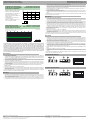
0
10
20
30
40
01234
X [m]
Y [mm] MLV12-54-2563
x
y
Charakteristische Ansprechkurve
Courbe de response caractéristique
Curve di risposta caratteristica
Characteristic response curve
Curva de respuesta característica
Möglicher Abstand (Versatz) zwischen
optischer Achse und Referenzobjekt.
Permissible distance (offset) between
optical axis and reference target.
Ecart possible entre l'axe optique et la
cible de référence.
Desplazamiento entre el eje óptico y
objeto de referencia.
Distanza possibile (sfalsato) tra l'asse
ottico e l'ogetto di riferimento.
0123
1
3
5
7
9
11
13
15
17
19
4567
Funktionsreserve, Stability control, Réserve de fonctionnement,
Reserva de función, Funzione riserva
MLV12-54-2563
x
X [m]
Relative Empfangslichtstärke
Intensité relative de la lumière reçue
Intensità relativa luce in ricezione
Relative received light strength
Potencia relativa de recepción lumínica
Descripción
Descrizione
Anzeigen/Bedienelemente
Indicators/operating means
1 Betriebsanzeige grün
2 Schaltanzeige gelb
3 Hell-/Dunkel-Schalter
4 Optische Achse Sender
5 Optische Achse Empfänger
1234
5
L
D
1 Operating display green
2 Switch state yellow
3 Light/dark switch
4 Optical axis emitter
5 Optical axis receiver
1234
5
L
D
-
 1
1
-
 2
2


Pepperl+Fuchs MLV12-54-2563/49/124 Instrucciones de operación
- Tipo
- Instrucciones de operación
en otros idiomas
Artículos relacionados
-
Pepperl+Fuchs RL80-54/25/31/76b/115 SET Instrucciones de operación
-
-
-
-
-
-
-
-
-