Truper CANT-6X El manual del propietario
- Categoría
- Herramientas eléctricas
- Tipo
- El manual del propietario

Code Model
16282
Applies for
CANT-6X
CANT-6X
IMPORTANT NOTE: This product should not be
exposed to dripping or splashing liquids.
Manual
6” Jointer
Power
1 Hp
CAUTION
ENGLISH
ESPAÑOL
Read this manual thoroughly
before using the tool.

KEEP THIS MANUAL
You will need the manual to check safety and caution rules,
assembly instructions, maintenance and operating procedures.
SAFETY INSTRUCTIONS
NOTICE: When using your tool, basic safety precautions
should always be followed to reduce the risk of personal
injury and equipment damage.
Read all instructions before using your tool.
1. Keep the work area in order. Benched and cluttered areas
are accident prone.
2. Observe the conditions of the work area. Do not use
machines or power tools in wet or damp areas. Do
not expose your tool to rain. Keep the work area well
lit. Do not use power tools in the presence of
flammable gases or liquids.
3. Protect yourself against electric shocks. Prevent
body contact with grounded surfaces such as pipes,
radiators, and refrigerators.
4. Keep children away. The machine must not be used by children
or persons with reduced physical, sensory or mental
capabilities, nor by persons with no experience or knowledge
in its use, unless they are supervised by a person responsible
for their safety or have received prior instructions on the use
of the machine. Children must be supervised to ensure that
they do not play with the machine. Close supervision should
be maintained if children or handicapped persons come near
or use any type of electrical appliance.
5. Keep the equipment stored when not in use. When not in
use, the tool should be stored in a dry, dust-free place. Always
keep your tool locked away so that it is out of the reach of
children.
6. Do not force the tool. It will do its job better and be safer
within the range for which it was designed. Do not use
improper attachments in an attempt to exceed the tool's
capacity.
7. Use the appropriate power tool. Do not use tools that are
too weak for heavy work. Do not use power tools for heavy
work for which they are not designed.
8. Wear appropriate clothing. Do not wear loose clothing,
gloves, neckties or jewelry that can get caught in moving
parts. Do not wear slippery footwear. Use a hair guard to
retain long hair.
9. Wear eye protection. Always use appropriate safety
accessories according to the Mexican Official
Standard (NOM), such as goggles, face shields and
dust masks, when working with materials that release
metal parts, chips or chemical dusts.
10. Do not use the power cable for purposes for which it is not
intended. Do not carry the tool by the cord and do not pull
on the cord to disconnect the plug from the socket base.
Protect the cord from heat, oil and sharp machinery.
11. Maintain proper balance on your feet at all times. Do not
reach over the machine or cross over when it is in operation.
12. Do not extend your radius of action. Avoid any posture that
causes fatigue. Make sure that your position is safe and that
you keep your balance.
13. Keep tools in the best condition. Keep tools clean for best
performance and safety. Follow instructions for lubrication
and change of accessories. Check tool cables periodically
and if damaged, take them to a Truper Authorized Service
Center for repair. Handles should always be kept clean, dry
and free of oil and grease.
14. Disconnect the tool. Disconnect the tool when
not in use before servicing.
15. Reduce the risk of accidental start-up. Do not
carry any tools with your finger on the switch while it
is connected to the power supply. Make sure the switch
is in the "OFF" position before connecting the power
cord.
16. Outdoor extensions. Use only approved and
properly marked outdoors extension cords.
17. Be alert. Watch what you are doing, use common sense. Do
not operate any tool when you are tired.
18. Check for damaged parts. Before continuing to use the
machine, guards or other moving parts that may be damaged
should be carefully checked to make sure they operate
properly and will work as intended. Check also the alignment
of the moving parts, if they are jammed or if there is any
probable breakage of the parts, check also the mounting, as
well as any other condition that may affect the operation of
the tool. All components must be properly assembled and
meet the requirements to ensure proper operation of the tool.
A guard or other part that is damaged should be properly
repaired or replaced. Any damaged control switch should be
replaced by a Truper Authorized Service Center. Do not use
any power tool on which the switch has no contact.
19. Replacement of parts and accessories. When
replacement parts are required, use only genuine
Truper replacement parts intended for use with this
tool.
20. CAUTION!! For your personal safety use only
accessories or additional equipment specified in the
operating instructions or recommended by the tool
manufacturer. The use of accessories other than those
specified in the operating instructions may result in
personal risk.
21. Hearing protection. Use ear protectors when
performing services that make noises above 85 dB.
If dust extraction and collection devices are connected to the tool,
check their connections and use them correctly.
The use of these devices reduces the risks related to dust.
2

3
ADDITIONAL SAFETY RULES FOR THE JOINTER
Working with wood can be dangerous if safety rules and operating
procedures are not followed. As with all tools, there are certain
risks involved in the operation of this product. Using the machine
with respect and caution will greatly reduce the chances of personal
injury. However, if normal safety precautions are overlooked or
ignored, personal injury to the operator could result. Safety
equipment such as guards, safety signs, safety glasses, dust masks
and ear protectors can reduce the risk of personal injury accidents.
But even the best guarding will not compensate for poor judgment
of risks, in CAUTION! or carelessness. Always use common sense
and take all necessary precautions in the workshop. If a procedure
seems dangerous, don't try it. Look for an alternative process that
is safe. REMEMBER: Your personal safety is your responsibility.
This machine was designed for certain applications only. Truper®
recommends that this machine not be modified and/or used in
applications for which it was not designed. If you have any questions
regarding a particular application, DO NOT use the machine until
you have made contact with us to determine if that application
can or should be performed by the machine.
1.- WARNING: Do not operate the jointer until it is completely
assembled and installed according to the instructions.
2.- IF YOU ARE NOT thoroughly familiar with the operation of
the jointer, obtain advice from a supervisor, instructor or
other qualified person.
3.- KEEP the cutting head sharp and free of rust and resins.
4.- BEFORE turning on the machine, check that the cutting head
guard is not damaged and that it operates freely.
5.- ALWAYS make sure that the exposed part of the cutting head
behind the fence is covered, especially when working close
to the edge.
6.- NEVER perform edging or planning operations with the
cutting head guard out of place.
7.- MAKE SURE that the feed and ejector tables are tight before
turning the tool on.
8.- NEVER turn on the jointer with the workpiece in contact
with the cutting head.
9.- ALWAYS hold the workpiece firmly against the work tables
and fence.
10.- NEVER perform a hands-free operation, i.e., using your hands
to support and guide the workpiece. ALWAYS use the backup
fence to position and guide the workpiece.
11.- AVOID awkward operations and hand positions where sudden
carelessness can cause your hands to pass over the
cutterhead.
12.- ALWAYS use push blocks for edging materials less than 75
mm (3") high or planning materials less than 75 mm (3")
thick.
13.- DO NOT edge materials less than 10" (25 cm) long, 3/4" (19
mm) narrow or 1/2" (13 mm) thick.
14.- DO NOT plane or level materials shorter than 10" (25 cm)
long, narrower than 3/4" (19 mm), wider than 6" (15 cm), or
thinner than 1/2" (13 mm).
15.- NEVER edge or plane cuts deeper than 3 mm (1/8"). On cuts
greater than 38 mm (1 1/2") wide, adjust the depth of cut to
1.5 mm (1/16") or less to avoid overheating the machine and
to minimize the possibility of kickback.
16.- MAINTAIN a proper relationship of the infeed and eject table
surface to the cutting head track.
17.- SUPPORT the workpiece adequately at all times during
operation; maintain control of the work at all times.
18.- DO NOT feed the workpiece back through the infeed table.
19.- DO NOT attempt to perform an abnormal or small operation
without studying it and using a suitable support block.
20.- TURN OFF the power supply before servicing or when making
any adjustments to the jointer.
21.- DISCONNECT the jointer from the power source and clean
it before leaving it.
22.- BE SURE to clean the work area before leaving the machine.
23.- IF any part of your jointer is lost, damaged or fails in any
way or any electrical component fails or does not work
properly, turn off the power switch and disconnect the plug
from the outlet. Have a Truper® Authorized Service Center
replace the missing, damaged or failed part before using it
again.
24.- SAVE THESE INSTRUCTIONS. Refer to them frequently and
use them to instruct others.

TECHNICAL CHARACTERISTICS:
Voltage: 115 V~ / 230 V~
Frequency: 60 Hz
Current: 12.4 A / 6.2 A
Motor rating power: 1 Hp
No-load engine speed: 3 450 r/min (RPM)
Cutting head speed: 5 000 r/min (RPM)
Work cycle: 120 minutes work per 30 minutes rest. Maximum six
hours daily.
Power cords grips: Type Y
All conductors are: 16 AWG x 3 C with insulation temperature of
221 ºF
Tool Build Quality: Basic insulation
Insulation class: Class I
Thermal insulation on motor winding: Class B
IMPORTANT NOTE: If the power cord is damaged, it must be
replaced by the manufacturer or Truper® Authorized Service Center
in order to avoid any risk of shock or major accident.
The construction of this product is designed so that its electrical
insulation is impaired by splashing or spillage of liquids during
operation.
WARNING: Before gaining access to the terminals, all power
circuits must be disconnected.
SPECIFICATIONS
Cutting head:
- Speed: 5 000 RPM
- Number of blades: 3
– Diameter: 2 1 /2”
Cutting capacity:
- Width: 6"
- Depth: 1/2"
- Grooving: 1/2" x 6"
Table:
- Length: 46"
- Height from floor: 32 1/2"
Support Guide:
- Size: 5” x 35”
- Inward and outward tilt of 45° and 90°
USE OF EXTENSION CORDS
When using extension cord, be sure to use sufficient gauge to carry
the current your product will draw. An undersized cord will cause
voltage drops in the line, resulting in loss of power and motor
overheating. The following table shows the correct size to use
depending on the length of the wire and the ampere rating indicated
on the tool nameplate. If in doubt use the next higher gauge.
Remember that the smaller the gauge number, the heavier the
wire. Make sure the extension cord is in good condition and has a
grounding conductor.
The power cables are color-coded as follows:
GREEN GROUND
WHITE NEUTRAL
BLACK CURRENT
Fig. 1
(1) It is allowed to be used as long as the extensions themselves
are provided with an overcurrent protection device.
(2) One of the conductors must be a grounding conductor. All
conductors are of the same designation (gauge) including the
grounding conductor.
Reference: NMX-J-195-ANCE
Make sure your extension cord is properly wired and in good
condition. Always replace a damaged extension cord, or have it
repaired by a qualified person before using it. Protect your
extension cords from sharp objects, excessive heat, and damp or
wet areas.
When operating a power tool outdoors, use an outdoor extension
cord marked "W-A" or "W". These cords are rated for outdoor use
and reduce the risk of electric shock.
Use a separate electrical circuit for your tools. This circuit should
have no conductors smaller than #12 gauge, and should be
protected with a 20 A time delay fuse. Before connecting the motor
to the power line, make sure the circuit breaker is in the OFF
position and that the electrical voltage is equal to the voltage
indicated on the motor nameplate. Operating at a lower voltage
will damage the motor.
CAUTION
Minimum gauge for extension cords (AWG)
(When using 127 V~ only)
Ampere capacity (2)
Higher
than
0 A
10 A
13 A
15 A
Up to
10 A
13 A
15 A
20 A
No. of
conductors
3
3
3
3
From 1.8 m
Up to 15 m
18 AWG (1)
16 AWG
14 AWG
8 AWG
Higher than
15 m
16 AWG
14 AWG
12 AWG
6 AWG
Extension cord
Minimum gauge for extension cords (AWG)
(When using 220 V~ only)
Ampere capacity (2)
Higher
than
0 A
11 A
15 A
17 A
Up to
11 A
15 A
17 A
23 A
No. of
conductors
3
3
3
3
From 1.8 m
Up to 15 m
18 AWG (1)
16 AWG
14 AWG
10 AWG
Higher than
15 m
16 AWG
14 AWG
12 AWG
8 AWG
Extension cord
4

1
2
3
4
5
6
13
7
89
11
12
10
14
15
INSTRUCTIONS FOR UNPACKING AND ASSEMBLY
Unpacking and cleaning the jointer.
Your new jointer and cabinet are shipped in two packages.
Carefully unpack the jointer, cabinet and all small parts from each
of the packages. Fig. 2 and 3 illustrate all parts shipped in the
jointer packages.
WARNING: The jointer is extremely heavy. It is suggested that
lifting or carrying the jointer or the jointer mechanism be done
by at least two people.
Remove the protective coating from the table surface and all
unpainted parts. This coating can be removed with a soft cloth
dampened with kerosene (do not use acetone, gasoline, or
thinner).
After cleaning, coat the table surface with a good quality wax
paste. Spread the wax perfectly on the worktable to avoid friction
with the workpiece.
Fig. 2
1. Jointer
2. Table lifting handle
3. Tilting handle of support guide
4. Cutting head guard
5. Cutting head pulley guard
6. Guide support assembly
7. 8 mm Allen wrench
8. 6 mm Allen wrench
9. 4 mm Allen wrench
10. 3 mm Allen wrench
11. 2.5 mm Allen wrench
12. 8 mm – 10 mm wrenches
13. 12 mm – 14 mm wrenches
14. Support blocks (2)
15. Support guide
16. Switch
17. Blade calibrator assembled set
16
17
5

ASSEMBLY INSTRUCTIONS
WARNING: For your own safety do not connect the jointer to the
power source until the jointer is completely assembled and you
have read and fully understand the owner's manual.
ELECTRICAL CABINET AND WIRING
Your jointer cabinet (A) Fig. 4 is shipped with the motor and switch
fully wired and the motor is factory assembled.
ASSEMBLING THE JOINTER TO THE CABINET
1. The jointer outfeed table should be installed on the same side
of the cabinet as the dust extractor hood (B) Fig. 5.
2. Remove the three screws (C) Fig. 5 and loosen the three screws
(D). Remove the rear panel (E) from the cabinet by lifting the
panel upwards.
3. Align the three holes (F) and (L) Fig. 6 on the top of the cabinet
with the three holes located on the base of the jointer and
attach the jointer to the cabinet with three M 10 Allen screws
(G) Fig. 7, three flat washers (H), three lock washers (J) and
three hex nuts (K).
Fig. 5
Fig. 6
Fig. 7
Fig. 4
Fig. 3
18
19
20
21
A
B
C
D
E
F
L
G
H
J
K
18. Cabinet with pre-wired switch
19. "V" band
20. Pulley
21. Wedge
22. Connector for dust extraction system
23. Safety pedal
24. Mounting screws
22
23
24
6

CAUTION: The jointer is extremely heavy. It is suggested that lifting
or carrying the jointer or the jointer mechanism be done by at
least two people.
IMPORTANT: The mounting screws for attaching the jointer to the
cabinet through the holes (F) must be installed from the bottom
up to the base of the jointer. The screw for mounting the jointer
to the cabinet through the hole (L) should be installed from the
bottom up to the base of the jointer.
FEED TABLE ADJUSTMENT HANDLE ASSEMBLY
1. Screw the lock nut (A) Fig. 9 clockwise onto the end of the
adjusting handle (B) Fig. 8 as far in as it will go.
2. Screw the handle (B) Fig. 8 into the block (C) Fig. 9 located
under the feed table (D) Fig. 8. Tighten the lock nut (A) against
the block (C) Fig. 9 as shown.
MOTOR PULLEY ASSEMBLY
Assemble the motor sheave (A) Fig. 10, to the motor shaft (B) with
the center of the pulley on the outside as shown. Make sure that
the shim (C) is inserted into the shim channel of the motor pulley
and motor shaft. Tighten the set screw (located in the center of
the pulley) against the motor shaft (B).
BELT ASSEMBLY AND PULLEY ALIGNMENT
1. Place the belt (A) Fig. 11, inside the grooves of the cutterhead
pulley (B) and motor pulley (C).
2. Ensure that the motor pulley (C), is aligned with the cutterhead
pulley (B) Fig. 11, by installing a square (D) on the face of each
pulley as shown in Fig. 12.
3. If adjustment is necessary, the motor pulley (C) Fig. 12 can be
moved on or off the motor shaft, or the motor can be moved
by loosening the four mounting screws, two of which are shown
(E) in Fig. 12. After adjustment has been completed, tighten
the four motor mounting screws or the set screw in the center
of the motor pulley, depending on which adjustment you have
made.
BELT TENSION ADJUSTMENT
Correct belt tension is obtained when there is a deflection of
approximately 1" at the center of the belt by applying light finger
pressure. If adjustment is necessary, the motor can be raised or
lowered by loosening the four mounting bolts, two of which are
shown in Fig. 12. (F),
Tighten the motor mounting hardware after belt tension has been
obtained.
NOTE: Make sure the motor pulley is aligned with the cutterhead
pulley. Reassemble the rear panel on the cabinet, which had been
removed in STEP 2 of the "ASSEMBLING THE CANTER TO THE
CABINET" section.
Fig. 10
Fig. 10
A
B
C
Fig. 11
A
B
C
Fig. 8
Fig. 8
B
C
D
Fig. 9
A
C
D
Fig. 12
E
D
C
F
B
7

CUTTER HEAD PULLEY GUARD ASSEMBLY
1. Install the pulley guard (C) Fig. 13, aligning the four holes (A)
with the four holes (B) at the rear of the jointer.
2. Using the wrench provided, attach the pulley guard (C) Fig.
14 to the jointer with four M 8 Allen screws, thrust washers
and flat washers (D) as shown in Fig. 14.
GUIDE BRACKET ASSEMBLY INSTALLATION
1. Attach the guide bracket assembly (A) Fig. 15 to the pulley
guard (B) using two M 8 socket head cap screws, thrust
washers and flat washers through the holes in the guide
bracket assembly, one of which is shown in Fig. 15 (C).
2. Fig. 16 illustrates the guide support assembly properly
mounted on the jointer.
SUPPORT RAIL ASSEMBLY
1. Align the two threaded holes (G) Fig. 17 in the guide support
(A) with the two holes (C) in the guide support assembly (B)
and fasten the guide support to the guide support assembly
with two M8 Allen screws, thrust washers and flat washers
(D).
2. Fig. 18 illustrates the support rail (A) properly mounted to the
rail bracket assembly (B).
3. Screw the two support rail adjustment handles (E) Fig. 18 into
the back of the support rail (A) as shown.
CUTTERHEAD GUARD ASSEMBLY
1. Remove the grub screw (not shown) from the post (A) Fig. 19
of the cutterhead guard (B).
2. Insert the post (A) Fig. 19 through the hole (C) in the feed
table.
NOTE: A spring is provided in the knob assembly (D) Fig. 20, which
returns the guard (B) onto the cutting head after the cut has been
made.
Fig. 14
C
D
Fig. 15 A
B
C
Fig. 16
Fig. 18
EA
B
Fig. 13
C
B
A
Fig. 17
G
A
C
D
B
8

3. Turn knob (D) to tension the spring inside the knob assembly
(D) Fig. 20 and engage into the slot in the post. If the spring
tension is too much or too little to return the cutting head
guard over the cutting head, adjust the spring tension as
necessary by removing the guard and turning the knob (D).
4. Thread the set screw (E) Fig. 20, which was removed in STEP
1, through the post (A) to hold the cutting head guard (B) in
its operating position.
5. Fig. 20 illustrates the cutting head guard (B) assembled to
the jointer.
CONNECTOR ASSEMBLY FOR A DUST EXTRACTOR SYSTEM
The jointer is equipped with a dust exhaust duct (A) Fig. 21, to
efficiently eject dust during the cutting operation. If you wish to
connect a dust extraction system to your jointer, the jointer is
equipped with a dust extraction system connector (B) Fig. 21 which
can be attached to the jointer cabinet (C) with four screws (D) as
shown.
CONNECTION OF THE JOINTER TO THE POWER SUPPLY
ELECTRICAL CONNECTIONS
A separate electrical circuit should be used for your tool. This
circuit should have a power cord no smaller than 12 gauge and
should be protected with a 20 A fuse. Have a Truper® Authorized
Service Center repair or replace any damaged cord immediately.
Before connecting the motor to the power source, make sure the
switch is in the off position and make sure the electrical current
of the circuit is equal to that of the machine shown on its
nameplate. Operating the motor at a lower voltage will damage
the motor.
WARNING: Do not expose the tool to rain or operate it in locations
where it may be exposed to rain.
GROUNDING INSTRUCTIONS
CAUTION: This tool must be grounded while in use to protect the
operator from electrical shock.
In the event of a malfunction or voltage drop, grounding provides
a path of least resistance to electric current to reduce the risk of
electric shock. This tool is equipped with a power cord that has a
grounding conductor and 2 current lines. The plug must be plugged
into an outlet that is properly installed and grounded in accordance
with local codes.
Improper connection of the equipment or grounding conductor
can cause a short circuit. If repair or replacement of the power
cord is necessary, do not connect the grounding conductor to a
live terminal.
Check with qualified electrician or service personnel if you do not
understand the grounding instructions or if you are in doubt as
to how to ground your tool.
The plug on the tool must match the receptacle. Never modify a
plug. Do not use any type of adapter for grounded tool plugs.
Modified plugs and different plugs increase the risk of electric
shock.
Have a damaged power cord repaired or replaced immediately by
a Truper Authorized Service Center.
This tool is designed for use on a normal 115 V~ or 230 V~ single
phase circuit.
Fig. 21
A
B
C
D
Fig. 19
A
B
C
Fig. 20
Fig. 20
EA
B
D
9

CAUTION: In all cases make sure that the outlet in question is
properly grounded. If you are not sure, have a qualified electrician
check the outlet.
VOLTAGE CHANGE
The motor included with your professional jointer is a dual
single-phase motor, i.e., it can operate on 115 V~ or 230 V~. The
single-phase motor is originally wired to operate at 115 V~, if you
wish to operate the machine at 230 V~, you will need to follow the
instructions below:
1. Unplug the machine from the electrical outlet.
2. The motor included with the jointer comes with six terminal
leads that are wired to operate at 115 V~. Reconnect these
terminal leads as indicated on the motor identification label
to 230 V~.
3. The on/off switch included with the jointer is a two-pole
switch that does not need to be changed to operate at
115 V~ or 230 V~.
ADJUSTING THE INFEED TABLE
1. To raise or lower the feed table, loosen the table locking
handle (A) Fig. 22, which is located behind the feed table and
loosen the table locking handle (B) Fig. 23, which is mounted
on the adjusting lever (C)
2. Raise or lower the infeed table with the adjustment lever (C)
Fig. 23.
3. IMPORTANT: When the infeed table is being lowered, the depth
stop (D) Fig. 24 will automatically stop the table at 3 mm (1/8")
depth of cut. To move the table beyond this point, the depth
stop must be raised at the same time the infeed table is being
lowered. Always make sure that the locking handles (A) Fig.
22 and (B) Fig. 23 are tightened before operating the jointer.
The locking handles are spring action and can be repositioned
by pulling out the handle and repositioning it on the knurled
nut located under the center of the handle.
4. The depth of cut on the infeed table (position of the table in
relation to the cutting circle) is indicated on the scale (E) Fig.
23.
NOTE: The maximum cutting depth of this jointer is 13 mm (1/2"),
which must be completed in several cuts in 3 mm (1/8") depth
increments.
10
Fig. 22
A
D
Fig. 24
B
C
Fig. 23
E
1 3 5 2 4 8
115 V230 V
WIRING DIAGRAM DIAGRAMA DE CONEXION DE CABLES
842531

Fig. 29
D
E
Fig. 30
F
PRESET STOPS ON THE FEEDING TABLE
Preset stops are provided to limit the height and depth of the
infeed table. To adjust the stops, follow the steps below:
1. Make sure the machine is disconnected from the power source.
2. Loosen the two lock nuts (A) and (B) Fig. 25 and turn the
adjusting screws (C) and (D) on the back of the feed table as
necessary. A good suggestion is to install the height stop
against the pin (E) for the final cut. This means you can quickly
install the feed table for a finish or end cut without needing
to check the scale and pointer. Also, the bottom stop (C) can
be installed against the pin (E) at the maximum depth of cut
if desired.
3. Tighten the lock nuts (A) and (B) Fig. 25 after adjustment has
been made.
SETTING THE OUTFEED TABLE
To perform accurate edging operations, the outfeed table must
be exactly level with the cutterhead blades at their highest point
in their revolution. This means that the blades should be parallel
to the outfeed table and equally projected from the cutting head.
To adjust the outfeed table, proceed as follows:
1. Make sure that the machine is disconnected from the power
source.
2. Loosen the locking screws (A) Fig. 26 and turn the knob (B),
when the outfeed table is exactly level with the cutting head
blades at the highest point in its revolution, tighten the screws
(A).
BLADE ADJUSTMENT
For accurate work, the blades must be level with the outfeed table.
If adjustment is necessary, proceed as follows:
1. Make sure that the machine is disconnected from the power
source.
2. Remove the set screw that holds the cutting head guard (A)
Fig. 27 in position and remove the cutting head guard.
3. Loosen the table locking handle and lower the feed table as
described in the "ADJUSTING THE FEED TABLE" section.
4. Place a steel straightedge on the outfeed table and extend it
over the cutting head as shown in Fig. 28.
5. Carefully rotate the cutting head by hand. The blades should
lightly touch the ruler.
6. If the blade is too high or too low at either end, slightly turn
the screws located on the counter blade (D) Fig. 29 clockwise
to loosen them, using the wrench (E) provided. Then adjust
the height of the blade by turning the lifting screws (F) Fig.
31 counterclockwise to lower the blade or clockwise to raise
the blade.
A
B
C
D
E
Fig. 25
Fig. 26
A
B
Fig. 25
Fig. 27
A
Fig. 28
BLADE
RULER
FEED TABLE
OUTPUT
TABLE
11

Fig. 38
Fig. 34
A
Fig. 38
Fig. 35
A
B
D
C
B
D
NOTE: If the blade is to be lowered, it will be necessary to push it
down with a piece of wood after turning the screws (F).
WARNING: Be very careful that your hands do not come into contact
with the blade as it is sharp.
IMPORTANT: Tighten the safety screws (D) Fig. 29, after the
adjustment has been made.
7. Repeat the procedure to adjust the remaining two blades if
necessary.
8. If the blades are installed too low, the edging result will be as
shown in Fig. 31 and the surface will be curved.
9. If the knives are installed too high, the workpiece will be
nibbled at the end of the cut as shown in Fig. 32.
10. It is recommended that a final check be made by running a 6"
(15 cm) to 8" (20 cm) workpiece over the blades. The
workpiece will rest firmly on the two tables as shown in Fig.
33 and with no open spaces under the final cut.
11. Reinstall the cutting head guard that was removed in STEP 2.
TABLE PIN SETTING
Pins are provided to eliminate any play that may be created
between the base dovetail assembly and the infeed and outfeed
tables of your jointer due to excessive use. The feeder table pin
(A) is shown in Fig. 34. Proper pin adjustment is necessary for
jointer operation. The jointer pins were adjusted from the factory
and should not need any further adjustment, however if it is ever
necessary to adjust them due to excessive wear, proceed as
follows:
1. To adjust the feed table pin, loosen the locking handles (C)
Fig. 35 and (F) Fig. 36. Loosen the three lock nuts (B) Fig. 35
and tighten or loosen the three set screws (D) as required.
NOTE: Adjust the lower screw first and as soon as this is done
adjust the upper screw and carefully raise the outer edge of the
table. This will compensate for any tendency of the table to become
uneven and will allow the pin to fit properly into the upper adjusting
screw. Tighten the three lock nuts (B) Fig. 35 and the two table
locking handles.
2. To adjust the outfeed table pin, loosen the safety handle (H)
Fig. 37. Loosen the two lock nuts (E) and tighten or loosen the
two adjusting screws (G) as required.
NOTE: Adjust the lower screw first and as soon as you have done
so, adjust the upper screw and carefully raise the outer edge of
the table. This will compensate for any tendency of the table to
become unlevel and allow the pin to properly fit the upper adjusting
screw. Tighten the two lock nuts (E) and the locking handle (H).
IMPORTANT: Do not leave the screws too loose or slack. It should
take some work to move the tables up or down. Your jointer is a
finishing machine and cannot be expected to do a good edging job
if the table is installed loosely, wobbly or has play.
Fig. 31
Fig. 32
Fig. 33
WORK
OUTFEED
TABLE FEED TABLE
BLADE
BLADE TOO LOW
BLADE TOO HIGH
BLADE IN THE RIGHT HEIGHT
WORK
OUTFEED
TABLE FEED TABLE
BLADE
WORK
OUTFEED
TABLE FEED TABLE
BLADE
12

OPERATION OF THE SUPPORT SLIDE
The support slide can be moved across the table and can be tilted
45° inward or outward, to adjust either slide position proceed as
follows:
NOTE: The switch has been removed from the illustration for clarity
of explanation only.
1. To move the fence across the table, loosen the safety handle
(A) Fig. 38 and turn the knob (B) until the fence is in the desired
position; tighten the safety handle (A). As the support fence
is moved across the work table, the cutting head rear guard
(C) Fig. 38 extends over the blades at the rear of the fence to
protect the operator.
NOTE: The safety handle (A) is spring-loaded and can be
repositioned by pulling out the handle and repositioning it on the
knurled nut located under the center of the handle
2. To tilt the support rail in or out, loosen the safety handle (D)
Fig. 38 While holding the rail tilt handle (E) Fig. 40 turn the
bump stop (F) Fig. 41, and tilt the support rail in or out to the
desired angle and tighten the safety handle (D) Fig. 38.
IMPORTANT: When bevel cutting and the angle is small, there is
little difference between whether the fence is turned in or out,
however, at large angles approaching 45°, there is increased
difficulty in holding the workpiece properly and securely against
the fence when the fence is tilted out. In these cases, it is
suggested that whenever possible, the support fence (G) be tilted
toward the table as shown in Fig. 40. The support fence will then
form a "V" with the tables and the workpiece will be easily pressed
into
t he
receptacle as it passes through the blades.
ADJUSTING THE SUPPORT GUIDE PRESET STOP
NOTE: The switch has been removed from the illustration for clarity
of explanation only.
The support slide has been equipped with preset stops that allow
quick tilting of the support slide to angles of 90° and 45°, inward
and outward from the table. To check and adjust the preset stops
proceed as follows:
1. Make sure the machine is disconnected from the power source.
2. Position the support fence at 90° in relation to the table. Make
sure the bump stop (F) Fig. 39 and 44 is lowered as shown and
tighten the screw (H) Fig. 39, contacting the bump stop (F);
then tighten the safety handle (D).
3. Place a square (K) Fig. 41 on the table against the support rail
as shown, to check if the support rail is at 90° in relation to
the table.
Fig. 36
F
Fig. 40
Fig. 37
H
E
G
Fig. 38
A
B
CD
D
E
G
Fig. 39
Fig. 40
F H
13

4. If adjustment is necessary, loosen the locking handle (D) Fig.
41 and the lock nut (L). Turn the adjusting screw (F) until you
are sure that the support guide is at 90° in relation to the
table and tighten the lock nut (L).
5. Rotate the bump stop (F) Fig. 41 and tilt the support slide out
as far as it will go and tighten the safety handle (D) Fig. 43.
Place a square (K) Fig. 43 on the table and against the support
slide to check if the support slide is 45° outwards in relation
to the table.
6. If adjustment to the preset stop is necessary, loosen the
locking handle (D) Fig. 42 and the lock nut (M) until you are
sure that the support rail is 45° out in relation to the table
and tighten the lock nut (M).
7. Tilt the support rail (G) Fig. 43 inward as far as it will go and
tighten the locking handle (D) Fig. 43. Using a square (K) on
the table and against the support rail, check if the support
rail is 45° inward in relation to the table.
8. If adjustment is necessary, loosen the lock nut (P) Fig. 43.
Turn the screw (R) until you are sure that the support rail is
45° inward and tighten the lock nut (P) and safety handle (D)
Fig. 42.
BLADE REPLACEMENT
If the blades are removed from the cutterhead to be replaced or
resharpened, be careful to follow the following steps to remove
them:
1. Disconnect the machine from the power source.
2. Move the support guide to the rear and remove the cutterhead
guard. Be extremely careful that your hands do not come in
contact with the cutting head blades.
3. Using the wrench (A) Fig. 44, slightly loosen the locking screws
(B) Fig. 44 in each blade slot to release the tension on the
cutting head by turning the screws (B) clockwise.
4. Loosen the screws again and remove the blade (C) Fig. 45 and
the counter blade (D).
5. Fig. 45 shows the blade (C) and counter blade (D) removed
from the cutting head. Remove the two remaining blades and
counter blades in the same manner.
6. Using the wrench provided, lower the two blade adjustment
blocks by turning the screws (F) Fig. 45, counterclockwise in
the three slots of the cutterhead.
7. Before replacing the blades, make sure that the counter blades
are completely clean and free of rubber and resin.
8. Place the counter blades (D) Fig. 45 and blades (C) into each
slot in the cutting head.
WARNING: Be very careful to touch the blades when inserting them
as they are very sharp.
Fig. 41
D
K
L
F
Fig. 42
D
M
Fig. 43
G
K
P R
Fig. 44
B
A
Fig. 45
Fig. 45
C
D
F
F
E
14

Push the blades down with a piece of wood as far as possible and
tighten the bolts (B)
Fig. 44 by turning each one counterclockwise just enough to hold
the blade in position. Replace the remaining two blades in the
same manner.
NOTE: The blades will be properly installed as shown in Fig. 46.
9. The blades are set correctly when the cutting edge of the
blade extends 1.52 mm (0.060") beyond the diameter of the
cutting head.
10. Carefully rotate the cutting head (G) Fig. 48 manually until
the round part of the cutting head is in the upper position as
shown.
11. Place a 1.52 mm (0.060") gauge (H) Fig. 47 on the cutterhead
and using a straight edge (J) on the outfeed table, adjust the
height of the outfeed table until it is 1.52 mm (0.060") above
the cutterhead diameter as shown.
12. Secure the outfeed table in position and remove the caliper
(H).
13. Lower the infeed table and place a ruler (J) Fig. 47 on the
outfeed table extending it over the cutting head as shown.
14. Rotate the cutting head by hand until the blade is at its highest
point on each side of the cutting head. To raise the blade, use
the wrench (E) Fig. 48 and turn the screw clockwise until the
blade touches the ruler (J) on each side and the center of the
cutting head when the blade is at its highest point. When you
are sure that the blade is properly adjusted, tighten the screws
(B) Fig. 44.
15. Adjust the remaining two blades in the same manner.
WARNING: Make sure all blades are securely fastened before
turning on the machine.
16. Replace the cutterhead guard after the adjustments are made.
MAINTENANCE AND REPAIRS
After considerable use, the blades may become worn, dull and not
perform an accurate edging job. However, if they are damaged by
working with hard materials, they can be sharpened as follows:
SHARPENING BLADES
Disconnect the machine from the power source. Use a fine
carborundum (silicon carbide) stone, cover one side with paper
as shown in Fig. 49, to avoid marking the table. Place the stone on
the feed table, lower the table and rotate the cutting head forward
until the stone rests flat on the bevel of the blades as shown. Hold
the cutting head and sharpen the beveled edge of the blades, doing
the same all along it by sliding the stone across the table. Do the
same operation on each of the three blades
OPERATION
The following instructions will tell the novice operator how to
begin jointer operations. Use scrap parts to check calibrations
and make final adjustments to the operation before attempting
regular work.
WARNING: Always use the cutterhead guard and keep hands away
from the cutterhead blades. WHENEVER POSSIBLE USE SUPPORT
BLOCKS TO PUSH THE WORK MATERIAL
DEFINITION OF EDGING AND PLANNING OPERATIONS
EDGING OPERATION
Edging is the simplest and most common of the operations that
can be performed with the jointer and is done to square and edge
a workpiece. The fence is framed with the table and the depth of
cut is installed at approximately 1/8". The workpiece is installed
on the jointer with the narrow edge of the workpiece on the infeed
table and the part of the workpiece with the largest surface area
against the support fence, as shown in Figures 50 and 51. The
workpiece is passed from the infeed table through the cutting
head to the ejector or outfeed table.
Fig. 47
J
G
H
Fig. 48
E
J
PAPEL
OUTFEED
TABLE FEEDING
TABLE
BLADE
CARBORUNDUM STONE
Fig. 49
15
Keep the surface of the cutter head parallel to the
blade and the blade parallel to the bar at its highest
point.
The face of the screw and the face of the cutting head
must be parallel.
WARNING: Make sure that the blades are installed correctly.

CAUTION: Never pass your hands directly over the cutting head
and always use support blocks to feed the workpiece when
possible. The hand on the outfeed table presses the workpiece
down so that the new edged surface makes perfect contact with
the table.
The hand on the infeed table (usually the right hand) should not
exert pressure on the workpiece, but simply advance it toward
the cutting head. Both hands should exert pressure to keep the
workpiece in contact with the fence.
IMPORTANT: Do not perform edging operations on material less
than 10" long, 3/4" narrow or 1/2" thick, Fig. 52.
PLANNING OPERATION
Planning or smoothing is identical to the edging operation except
for the position of the workpiece on the jointer. For planning the
largest flat surface of the workpiece is installed on the jointer
infeed table with the narrow edge of the workpiece against the
support fence, as shown in Fig. 58. The workpiece is passed from
the infeed table through the cutting head to the outfeed table
producing a smooth surface on the workpiece. Always use support
blocks when performing a planning operation and never pass your
hands directly over the cutterhead.
BEVELING
To make a bevel cut, secure the support fence at the required
angle and slide the workpiece through the blades while holding it
firmly against the support fence and tables. Several passes may
be necessary to obtain the desired result. When the angle is small,
there is little difference between whether the fence is turned in
or out, however, at large angles approaching 45°, there is increased
difficulty in holding the workpiece properly when the fence is
turned out. The advantage of the support slide being able to rotate
in both directions is appreciated under these conditions.
When turned inward, the fence forms a "V" figure with the tables
and the workpiece slides more easily through the pocket and blades
as shown in Fig. 53. If the bevel is taken out of the workpiece in a
direction that involves cutting against the grain of the wood, it
will be better to turn the fence outward.
NARROWING CUTS
One of the most useful applications of the jointer is to cut an edge
to narrow it. The method that can be used varies according to the
job. Narrow furniture legs are a common example of this
application.
Instead of putting the workpiece on the infeed table, slide the end
of the workpiece onto the outfeed table, do this carefully, as the
workpiece contacts the blades, they will make a small cut to the
workpiece with the tendency to kickback unless the workpiece is
held firmly. Now push the workpiece forward as in ordinary edging.
The effect is to flatten all the material in front of the blades to
increase the depth, leaving a narrow surface.
The left edge caused by the knives when starting the narrowing
cut can be eliminated by making a slight cut according to the
regular method for edging, with the feed table raised to its usual
position or by sanding it down.
Practice is required to perform this operation and it is advisable
for the beginner to make trial cuts in scrap material before
performing the work. Taper cuts along a workpiece and numerous
other special operations can be easily performed by an experienced
worker.
SLOT CUTTING
When cutting a slot, as shown in Fig. 54, the cutting head guard
must be removed. AFTER THE SLOT CUTTING IS COMPLETED, MAKE
SURE THE GUARD IS INSTALLED BACK IN PLACE.
Fig. 50
WORK
OUTFEED
TABLE FEEDING TABLE
BLADE
Fig. 51
Fig. 52
10” MINIMUM
1/2”
MINIMUM
3/8” MAXIMUM
Fig. 53
16

Fig. 57
BLADE
OUTFEED
TABLE FEEDING TABLE
WRONG FEED
Fig. 58
BLADE
OUTFEED
TABLE FEEDING TABLE
RIGHT FEED
WARNING: Use support blocks whenever possible.
1. Adjust the support fence so that the distance between the
end of the blades and the support fence is equal to the width
of the groove to be made.
2. Lower the feed table by an amount equal to the depth of the
slot to be made. If the groove is very deep, it may be necessary
to make the cut in two or more passes. In that case, the table
is lowered by an amount equal to about half the depth of the
slot for the first pass and then the table is lowered again to
the correct depth to finish the cut.
EDGING OR PLANNING WARPED WOOD
If the wood to be edged is uneven or curved, make light cuts until
the surface is flat. Avoid forcing the wood against the table as
excessive pressure may increase its speed as it passes over the
blades and slow it down, causing the board to remain curved or
misaligned even after the cut is completed.
EDGING SHORT OR THIN WOOD
When edging short or thin pieces, always use support blocks to
eliminate hand hazards. Fig. 55 illustrates the proper use of support
blocks while edging a board.
IMPORTANT: Do not perform planning operations on material less
than 10" (25 cm) long, narrower than 3/4" (19 mm), wider than 6"
(15 cm) or thinner than 1/2" (13 mm). See Fig. 56.
DIRECTION OF WOOD GRAIN
Avoid feeding the work stock into the jointer against the grain of
the wood as shown in Fig. 57. This will result in popping and chipped
edges.
Feed the work material into the jointer with the grain of the wood
as shown in Fig. 58 to obtain a smooth, soft surface.
Fig. 54
Fig. 55
Fig. 56
10” MINIMUM
1/2”
MINIMUM
3/8”
MAXIMUM
17

CONSTRUCTION OF A PUSH BAR
Narrow workpieces, less than 10” long should be handled
with a push bar and a push block. Fig. 59 is a pattern for
making a push bar.
Fig. 59
18
PUSH BAR
Made of 1/2" or 3/4" lumber less than the
thickness of the board to be cut.
Cut here to push 1/4" wood.
Cut here to push 1/2" wood.
1/2" squares
To help prevent hands
from slipping.

19
Authorized Service Centers
In the event of any problem contacting a Truper Authorized Service Center, please see our webpage
www.truper.com to get an updated list, or call our toll-free numbers 800 690-6990 or 800 018 7873 to get
information about the nearest Service Center.
AGUASCALIENTES
BAJA
CALIFORNIA
BAJA
CALIFORNIA SUR
CAMPECHE
CHIAPAS
CHIHUAHUA
MEXICO CITY
COAHUILA
COLIMA
DURANGO
ESTADO DE
MÉXICO
GUANAJUATO
GUERRERO
HIDALGO
JALISCO
MICHOACÁN
MORELOS
NAYARIT
NUEVO LEÓN
OAXACA
PUEBLA
QUERÉTARO
QUINTANA ROO
SAN LUIS
POTOSÍ
SINALOA
SONORA
TABASCO
TAMAULIPAS
TLAXCALA
VERACRUZ
YUCATÁN
DE TODO PARA LA CONSTRUCCIÓN
GRAL. BARRAGÁN #1201, COL. GREMIAL, C.P. 20030,
AGUASCALIENTES, AGS. TEL.: 449 994 0537
SUCURSAL TIJUANA
AV. LA ENCANTADA, LOTE #5, PARQUE INDUSTRIAL EL
FLORIDO II, C.P 22244, TIJUANA, B.C.
TEL.: 664 969 5100
FIX FERRETERÍAS
FELIPE ÁNGELES ESQ. RUIZ CORTÍNEZ S/N, COL. PUEBLO
NUEVO, C.P. 23670, CD. CONSTITUCIÓN, B.C.S.
TEL.: 613 132 1115
TORNILLERÍA Y FERRETERÍA AAA
AV. ÁLVARO OBREGÓN #324, COL. ESPERANZA
C.P. 24080 CAMPECHE, CAMP. TEL.: 981 815 2808
FIX FERRETERÍAS
AV. CENTRAL SUR #27, COL. CENTRO, C.P. 30700,
TAPACHULA, CHIS. TEL.: 962 118 4083
SUCURSAL CHIHUAHUA
AV. SILVESTRE TERRAZAS #128-11, PARQUE INDUSTRIAL
BAFAR, CARRETERA MÉXICO CUAUHTÉMOC, C.P. 31415,
CHIHUAHUA, CHIH. TEL. 614 434 0052
FIX FERRETERÍAS
EL MONSTRUO DE CORREGIDORA, CORREGIDORA # 22,
COL. CENTRO, C.P. 06060, CUAUHTÉMOC, CDMX.
TEL: 55 5522 5031 / 5522 4861
SUCURSAL TORREÓN
CALLE METAL MECÁNICA #280, PARQUE INDUSTRIAL
ORIENTE, C.P. 27278, TORREÓN, COAH.
TEL.: 871 209 68 23
BOMBAS Y MOTORES BYMTESA DE MANZANILLO
BLVD. MIGUEL DE LA MADRID #190, COL. 16 DE
SEPTIEMBRE, C.P. 28239, MANZANILLO, COL.
TEL.: 314 332 1986 / 332 8013
TORNILLOS ÁGUILA, S.A. DE C.V.
MAZURIO #200, COL. LUIS ECHEVERRÍA, DURANGO,
DGO.TEL.: 618 817 1946 / 618 818 2844
SUCURSAL CENTRO JILOTEPEC
AV. PARQUE INDUSTRIAL 1, PARQUE INDUSTRIAL
JILOTEPEC, JILOTEPEC, EDO. DE MÉX. C.P. 54257,
TEL: 761 782 9101 EXT. 5728 Y 5102
CÍA. FERRETERA NUEVO MUNDO S.A. DE C.V.
AV. MÉXICO - JAPÓN #225, CD. INDUSTRIAL, C.P. 38010,
CELAYA, GTO. TEL.: 461 617 7578 / 79 / 80 / 88
CENTRO DE SERVICIO ECLIPSE
CALLE PRINCIPAL MZ.1 LT. 1, COL. SANTA FE, C.P. 39010,
CHILPANCINGO, GRO. TEL.: 747 478 5793
FERREPRECIOS S.A. DE C.V.
LIBERTAD ORIENTE #304 LOCAL 30, INTERIOR DE PASAJE
ROBLEDO, COL. CENTRO, C.P. 43600, TULANCINGO,
HGO. TEL.: 775 753 6615 / 775 753 6616
SUCURSAL GUADALAJARA
AV. ADOLFO B. HORN # 6800, COL: SANTA CRUZ DEL
VALLE, C.P.: 45655, TLAJOMULCO DE ZUÑIGA, JAL.
TEL.: 33 3606 5285 AL 90
FIX FERRETERÍAS
AV. PASEO DE LA REPÚBLICA #3140-A, COL.
EX-HACIENDA DE LA HUERTA, C.P. 58050, MORELIA,
MICH. TEL.: 443 334 6858
FIX FERRETERÍAS
CAPITÁN ANZURES #95, ESQ. JOSÉ PERDIZ, COL.
CENTRO, C.P. 62740, CUAUTLA, MOR.
TEL.: 735 352 8931
HERRAMIENTAS DE TEPIC
MAZATLAN #117, COL. CENTRO, C.P. 63000, TEPIC, NAY.
TEL.: 311 258 0540
SUCURSAL MONTERREY
CARRETERA LAREDO #300, 1B MONTERREY PARKS,
COLONIA PUERTA DE ANÁHUAC, C.P. 66052, ESCOBEDO,
NUEVO LEÓN, TEL.: 81 8352 8791 / 81 8352 8790
FIX FERRETERÍAS
AV. 20 DE NOVIEMBRE #910, COL. CENTRO, C.P. 68300,
TUXTEPEC, OAX. TEL.: 287 106 3092
SUCURSAL PUEBLA
AV PERIFÉRICO #2-A, SAN LORENZO ALMECATLA,
C.P. 72710, CUAUTLACINGO, PUE.
TEL.: 222 282 8282 / 84 / 85 / 86
ARU HERRAMIENTAS S.A DE C.V.
AV. PUERTO DE VERACRUZ #110, COL. RANCHO DE
ENMEDIO, C.P. 76842, SAN JUAN DEL RÍO, QRO.
TEL.: 427 268 4544
FIX FERRETERÍAS
CARRETERA FEDERAL MZ. 46 LT. 3 LOCAL 2, COL EJIDAL,
C.P. 77710 PLAYA DEL CARMEN, Q.R.
TEL.: 984 267 3140
FIX FERRETERÍAS
AV. UNIVERSIDAD #1850, COL. EL PASEO, C.P. 78320,
SAN LUIS POTOSÍ, S.L.P. TEL.: 444 822 4341
SUCURSAL CULIACÁN
AV. JESÚS KUMATE SUR #4301, COL. HACIENDA DE LA
MORA, C.P. 80143, CULIACÁN, SIN.
TEL.: 667 173 9139 / 173 8400
FIX FERRETERÍAS
CALLE 5 DE FEBRERO #517, SUR LT. 25 MZ. 10, COL.
CENTRO, C.P. 85000, CD. OBREGÓN, SON.
TEL.: 644 413 2392
SUCURSAL VILLAHERMOSA
CALLE HELIO LOTES 1, 2 Y 3 MZ. #1, COL. INDUSTRIAL,
2A ETAPA, C.P. 86010, VILLAHERMOSA, TAB.
TEL.: 993 353 7244
VM ORINGS Y REFACCIONES
CALLE ROSITA #527 ENTRE 20 DE NOVIEMBRE Y GRAL.
RODRÍGUEZ, FRACC. REYNOSA, C.P. 88780, REYNOSA,
TAMS. TEL.: 899 926 7552
SERVICIOS Y HERRAMIENTAS INDUSTRIALES
PABLO SIDAR #132, COL . BARRIO DE SAN BARTOLOMÉ,
C.P. 90970, SAN PABLO DEL MONTE, TLAX.
TEL.: 222 271 7502
LA CASA DISTRIBUIDORA TRUPER
BLVD. PRIMAVERA. ESQ. HORTENSIA S/N, COL.
PRIMAVERA C.P. 93308, POZA RICA, VER.
TEL.: 782 823 8100 / 826 8484
SUCURSAL MÉRIDA
CALLE 33 #600 Y 602, LOCALIDAD ITZINCAB Y MULSAY,
MPIO. UMÁN, C.P. 97390, MÉRIDA, YUC.
TEL.: 999 912 2451

www.truper.com
05-2022
20
Warranty
policy
1
YEAR
16282
Warranty
policy
Code
CANT-6X
Model Brand
Stamp of the business. Delivery date:
Warranty. Duration: 1 year. Coverage: parts, components and workmanship against manufacturing or
operating defects, except if used under conditions other than normal; when it was not operated in accordance
with the instructive; was altered or repaired by personnel not authorized by Truper®. To make the warranty
valid, present the product, stamped policy or invoice or receipt or voucher, in the establishment where you
bought it or in Corregidora 22, Centro, Cuauhtémoc, CDMX, 06060, where you can also purchase parts,
components, consumables and accessories. It includes the costs of transportation of the product that derive
from its fulfillment of its service network. . Phone number 800-018-7873. Made in China. Imported by Truper,
S.A. de C.V. Parque Industrial 1, Parque Industrial Jilotepec, Jilotepec, Edo. de Méx. C.P. 54257, Phone number
761 782 9100.

Código Modelo
16282
Este instructivo es para:
CANT-6X
CANT-6X
NOTA IMPORTANTE: Este producto no debe quedar
expuesto a goteo o salpicaduras por líquidos.
Instructivo para
Canteadora de 6”
15 cm
Lea este instructivo por completo
antes de usar la herramienta.
ATENCIÓN
Potencia
750 W
ESPAÑOL

CONSERVE ESTE INSTRUCTIVO
Usted necesitará el instructivo para checar las reglas de seguridad
y precaución, instrucciones de ensamble, procedimientos de
mantenimiento y operación.
INSTRUCCIONES DE SEGURIDAD
AVISO: Cuando utilice su herramienta, siempre deben
seguirse algunas precauciones básicas de seguridad para
reducir riesgos de daños personales y daños al equipo.
Lea todas las instrucciones antes de usar su herramienta.
1. Mantenga el área de trabajo en orden. Las áreas y bancos
desordenados propician accidentes.
2. Observe las condiciones del área de trabajo. No utilice
máquinas o herramientas eléctricas en áreas mojadas o
húmedas. No exponga su herramienta a la lluvia. Mantenga
el área de trabajo bien iluminada. No utilice herramientas
eléctricas en presencia de gases o líquidos inflamables.
3. Prevéngase contra los choques eléctricos. Prevenga
el contacto del cuerpo con superficies conectadas a tierra
tales como tuberías, radiadores, y refrigeradores.
4. Mantenga a los niños alejados. La máquina no debe de ser
utilizada por niños ni por personas con capacidades físicas,
sensoriales o mentales reducidas; tampoco por personas sin
experiencia o conocimientos en su uso, a menos que estén
supervisadas por una persona responsable de su seguridad o
reciban instrucciones previas sobre el uso de la máquina.
Los niños deben de estar bajo supervisión para asegurarse de
que no jueguen con la máquina. Se debe de mantener una estricta
supervisión si niños o personas discapacitadas llegan a utilizar
cualquier tipo de aparato electrodoméstico o estén cerca de él.
5. Mantenga guardado el equipo mientras no esté en uso. Cuando
no esté en uso, la herramienta debe guardarse en un lugar seco
y libre de polvo. Siempre guarde su herramienta bajo llave para
que no esté al alcance de los niños.
6. No fuerce la herramienta. Esta hará mejor su trabajo y será
más segura dentro del rango para la cual fue diseñada. No utilice
aditamentos inapropiados para intentar exceder la capacidad
de la herramienta.
7. Utilice la herramienta eléctrica adecuada. No utilice
herramientas demasiado débiles para ejecutar trabajos pesados.
No utilice herramientas eléctricas para trabajos pesados para
los cuales no ha sido diseñada.
8. Utilice la indumentaria apropiada. No utilice ropa suelta,
guantes, corbatas o joyería que pueda ser atrapada en las partes
móviles. No utilice calzado resbaloso. Utilice algún protector de
cabello para retener el cabello largo.
9. Utilice protección para ojos. Siempre utilice
accesorios de seguridad apropiados por la Norma Oficial
Mexicana (NOM), como es el caso de gogles, caretas y
mascarillas contra polvo, cuando trabaje con materiales
que despidan partes metálicas, virutas o polvos químicos.
10. No use el cable de alimentación para fines para los cuales no
está dispuesto. No lleve la herramienta colgada del cable y no
tire de éste para desconectar la clavija de la base de enchufe.
Proteja el cable contra el calor, el aceite y las esquinas afiladas.
11. Mantenga el balance adecuado todo el tiempo sobre sus pies.
No trate de alcanzar algo sobre la máquina o se cruce cuando
esté en funcionamiento.
12. No extienda su radio de acción. Evite toda postura que cause
cansancio. Cuide de que su posición sea segura y de que conserve
el equilibrio.
13. Mantenga las herramientas en las mejores condiciones.
Mantenga las herramientas limpias para tener la mejor ejecución
y seguridad. Siga las instrucciones para la lubricación y cambio
de accesorios. Verifique los cables de la herramienta
periódicamente y si se encuentran dañados, llévelos a reparar
a un Centro de Servicio Autorizado Truper®. Los mangos o manijas
deben siempre permanecer limpios, secos y libres de aceite y
grasas.
14. Desconecte la herramienta. Desconecte la
herramienta cuando no esté en uso, antes de proceder
al mantenimiento.
15. Reduzca el riesgo de arranques accidentales. No
lleve ninguna herramienta con el dedo puesto sobre el
interruptor mientras esté conectado a la red eléctrica.
Asegúrese de que el interruptor esté en la posición
“apagado” (OFF) antes de conectar el cable de
alimentación.
16. Extensiones para exterior. En el exterior, utilice solamente cables
de extensión homologados y convenientemente marcados.
17. Manténgase alerta. Fíjese en lo que está haciendo, utilice su
sentido común. No opere ninguna herramienta cuando esté
cansado.
18. Cheque las partes dañadas. Antes de continuar utilizando la
máquina, los protectores u otras partes móviles que pudieran
estar dañadas deben ser cuidadosamente revisadas, para
asegurarse que operan apropiadamente y trabajarán como debe
ser. Revise también la alineación de las partes móviles, si están
atascadas, o si hay alguna probable ruptura de las partes, cheque
también el montaje, así como cualquier otra condición que pueda
afectar la operación de la herramienta. Todos los componentes
deben estar montados adecuadamente y cumplir los requisitos
para garantizar el correcto funcionamiento del aparato. Un
protector u otra parte que estén dañadas deberán ser
apropiadamente reparadas o cambiadas. Todo interruptor de
mando deteriorado, deberá ser reemplazado por un Centro de
Servicio Autorizado Truper®. No utilice ninguna herramienta
eléctrica en la cual el interruptor no tenga contacto.
19. Reemplazo de partes y accesorios. Cuando necesite
remplazar las piezas, utilice solamente refacciones
originales Truper®, destinados para usarse con está
herramienta.
20. ¡¡ ATENCIÓN !! Para su seguridad personal utilice
únicamente los accesorios o aparatos adicionales
indicados en las instrucciones de manejo o recomendados
por el fabricante de la herramienta. La utilización de
accesorios diferentes a los indicados en las instrucciones
de manejo, puede acarrear riesgo personal.
21. Protección para oídos. Utilice protectores auriculares,
cuando ejecute servicios que hagan ruidos superiores a
85 dB.
En caso de contar con dispositivos de extracción y recolección de
polvo conectados a la herramienta, verifique sus conexiones y úselos
correctamente.
El uso de estos dispositivos reduce los riesgos relacionados con el
polvo.
2

REGLAS DE SEGURIDAD ADICIONALES PARA LA CANTEADORA
Trabajar con madera puede ser peligroso si las reglas de seguridad
y los procedimientos de operación no se siguen. Como en el caso de
todas las herramientas, se corren ciertos riesgos con la operación
de este producto. Usando la máquina con respeto y precaución se
reducirán considerablemente las posibilidades de que se presenten
daños personales. Sin embargo, si las precauciones normales de
seguridad se pasan por alto o son ignoradas se podrían causar lesiones
personales al operador. El equipamiento de seguridad como las
guardas, las señales de seguridad, los lentes de seguridad, las
mascarillas anti polvo y los protectores para los oídos, pueden
disminuir el riesgo de que sucedan accidentes que provoquen daños
personales. Pero incluso la mejor guarda no compensará un juicio
pobre de los riesgos, la desatención ni un descuido. Siempre use el
sentido común y tome en cuenta todas las precauciones necesarias
en el taller. Si un procedimiento parece peligroso no lo intente. Busque
un proceso alternativo que sea seguro. RECUERDE : Su seguridad
personal es su responsabilidad.
Esta máquina fue diseñada solo para ciertas aplicaciones. Truper®
recomienda que esta máquina no sea modificada y / o usada en
aplicaciones para las cuales no fue diseñada. Si usted tiene alguna
pregunta relativa a una aplicación en particular, NO use la máquina
hasta que haya hecho contacto con nosotros para determinar si dicha
aplicación puede o debe ser realizada por la máquina.
1.- ADVERTENCIA: No opere la canteadora hasta que este
completamente ensamblada e instalada de acuerdo a las
instrucciones.
2.- SI NO ESTA perfectamente familiarizado con el funcionamiento
de la canteadora, obtenga asesoría de un supervisor, instructor
u otra persona calificada.
3.- MANTENGA el cabezal de corte afilado y libre de óxido y
resinas.
4.- ANTES de encender la máquina, revise que la guarda del
cabezal de corte no esté dañada y que opere libremente.
5.- SIEMPRE asegúrese de que la parte expuesta del cabezal de
corte que se encuentra detrás de la guía esté cubierta,
especialmente cuando trabaje cerca de la orilla.
6.- NUNCA realice operaciones de canteado o cepillado con la
guarda protectora del cabezal de corte fuera de su lugar.
7.- ASEGÚRESE de que las mesas de alimentación y expulsión
estén apretadas antes de encender la herramienta.
8.- NUNCA encienda la canteadora con la pieza de trabajo haciendo
contacto con el cabezal de corte.
9.- SIEMPRE sostenga firmemente la pieza de trabajo contra las
mesas de trabajo y la guía.
10.- NUNCA realice una operación a manos libres, es decir usando
sus manos para soportar y guiar la pieza de trabajo. SIEMPRE
use la guía de respaldo para posicionar y guiar la pieza de
trabajo.
11.- EVITE operaciones extrañas y posiciones de las manos donde
repentinamente un descuido pueda causar que sus manos
pasen sobre el cabezal de corte.
12.- SIEMPRE use bloques de empuje para cantear materiales
menores a 75 mm (3”) de alto o cepillar materiales menores
a 75 mm (3”) de grueso.
13.- NO CANTEE en materiales menores a 25 cm (10”) de largo,
19 mm (3/4”) de angosto o 13 mm (1/2”) de grueso.
14.- NO realice operaciones de cepillado o nivelado en materiales
menores a 25 cm (10”) de largo, menos angosto que 19 mm
(3/4”), más ancho que 15 cm (6”) o más delgado que 13 mm
(1/2”)
15.- NUNCA cantee o cepille cortes más profundos a 3 mm (1/8”)
En cortes mayores a 38 mm (1 1/2”) de ancho, ajuste la
profundidad de corte en 1.5 mm (1/16”) o menos para evitar
un sobrecalentamiento en la máquina y para minimizar la
posibilidad de un contragolpe, (que la pieza de trabajo se
revierta contra el operador).
16.- MANTENGA una apropiada relación de la superficie de la mesa
de alimentación y de expulsión con la vía del cabezal de corte.
17.- APOYE la pieza de trabajo adecuadamente todo el tiempo
durante la operación; mantenga el control del trabajo en todo
momento.
18.- NO regrese la pieza de trabajo a través de la mesa de
alimentación.
19.- NO intente realizar una operación anormal o pequeña sin
estudiarla y usar un bloque de apoyo adecuado.
20.- CORTE el suministro de energía antes de darle servicio o
cuando se le haga un ajuste a la canteadora.
21.- DESCONECTE la canteadora de la fuente de energía y límpiela
antes de dejarla.
22.- ASEGÚRESE de limpiar el área de trabajo antes de dejar la
máquina.
23.- SI una parte de su canteadora se pierde, daña o falla de alguna
forma o cualquier componente eléctrico falla o no trabaja
adecuadamente, apague el interruptor y desconecte la clavija
del tomacorriente. Haga que un Centro de Servicio Autorizado
Truper® reemplace la pieza perdida, dañada o que falló, antes
de volver a utilizarla.
24.- GUARDE ESTAS INSTRUCCIONES. Refiérase a ellas
frecuentemente y úselas para instruir a otros.
3

CARACTERíSTICAS TÉCNICAS:
Tensión: 115 V~ / 230 V~
Frecuencia: 60 Hz
Corriente: 12.4 A / 6.2 A
Potencia nominal del motor: 750 W (1 Hp)
Velocidad del motor sin carga: 3 450 r/min
Velocidad del cabezal de corte: 5 000 r/min
Ciclo de trabajo: 120 minutos de trabajo por 30 minutos de descanso.
Máximo diario 6 horas.
El cable de alimentación tiene sujeta-cables tipo: Y
Todos los conductores son: 16 AWG x 3C con temperatura de
aislamiento de 105 ˚C
La clase de construcción de la herramienta es: Aislamiento básico.
Clase de aislamiento: Clase I
La clase de aislamiento térmico de los devanados del motor:
Clase B
NOTA IMPORTANTE: Si el cable de alimentación se daña, éste debe
ser reemplazado por el fabricante o Centro de Servicio Autorizado
Truper®, con el fin de evitar algún riesgo de descarga o accidente
considerable.
La construcción de este producto esta diseñada de manera que su
aislamiento eléctrico es alterado por salpicaduras o derramamiento
de líquidos durante su operación.
ADVERTENCIA: Antes de obtener acceso a las terminales,
todos los circuitos de alimentación deben ser desconectados.
ESPECIFICACIONES:
Cabezal de corte:
• Velocidad: 5 000 r/min
• Número de cuchillas: 3
• Diámetro: 65 mm (2 1/2")
Capacidad de corte:
• Ancho: 15 cm (6”)
• Profundidad: 13 mm (1/2”)
• Ranurado: 13 mm x 15 cm (1/2” x 6”)
Mesa:
• Largo: 115 cm (46”)
• Altura desde el suelo: 83 cm (32 1/2”)
Guía de apoyo:
• Tamaño: 12.5 cm x 89 cm (5” x 35”)
• Inclinación: hacia adentro y hacia afuera de 45˚ y 90˚
USO DE EXTENSIONES
Al usar un cable de extensión, asegúrese de usar el calibre suficiente
para transportar la corriente que consumirá su producto. Un cable
de un calibre inferior ocasionará caídas de tensión en la línea, teniendo
como resultado pérdida de potencia y sobrecalentamiento del motor.
La siguiente tabla muestra el tamaño correcto que debe usarse
dependiendo de la longitud del cable y de la capacidad de amperes
indicada en la placa de datos de la herramienta. Si tiene dudas use
el siguiente calibre más alto. Recuerde que mientras más pequeño
sea el número del calibre, más pesado será el cable. Asegúrese de
que el cable de extensión esté en buen estado y que cuente con un
conductor de puesta a tierra.
Asegúrese de que su cable de extensión esté correctamente cableado
y en buen estado. Siempre reemplace un cable de extensión dañado,
o haga que sea reparado por una persona calificada antes de usarlo.
Proteja sus cables de extensión de objetos cortantes, calor excesivo
y áreas húmedas o mojadas.
Cuando opere una herramienta eléctrica en exteriores, use un cable
de extensión para exteriores marcado “W-A” o “W”. Estos cables
tienen capacidad de uso en exteriores y reducen el riesgo de una
descarga eléctrica.
Use un circuito eléctrico separado para sus herramientas. Este circuito
no debe tener conductores con un calibre inferior al #12, y debe
estar protegido con un fusible con demora de tiempo de 20 A Antes
de conectar el motor a la línea de corriente, asegúrese de que el
interruptor esté en la posición OFF y que la tensión eléctrica sea
igual a la indicada en la placa de datos del motor. Si se opera con una
tensión menor, se dañará el motor.
(1) Se permite utilizarlo siempre y cuando las extensiones mismas
cuenten con un artefacto de protección contra sobrecorriente.
(2) Uno de los conductores debe ser conductor para puesta a tierra.
Todos los conductores son de la misma designación (calibre)
incluyendo el de puesta a tierra.
Referencia: NMX-J-195-ANCE
Calibre mínimo para cables de extensión (AWG)
(cuando se usan 127 V~ solamente)
Capacidad en Amperes
(2)
Mayor de
0 A
10 A
13 A
15 A
Hasta
10 A
13 A
15 A
20 A
No. de
conductores
3
3
3
3
De 1.8 m
hasta 15 m
18 AWG (1)
16 AWG
14 AWG
8 AWG
Mayor de 15 m
16 AWG
14 AWG
12 AWG
6 AWG
Calibre de extensión
Calibre mínimo para cables de extensión (AWG)
(Cuando se usan 220 V~ solamente)
Capacidad en Amperes (2)
Mayor de
0 A
11 A
15 A
17 A
Hasta
11 A
15 A
17 A
23 A
No. de
conductores
3
3
3
3
De 1.8 m
hasta 15 m
18 AWG (1)
16 AWG
14 AWG
10 AWG
Mayor de 15 m
16 AWG
14 AWG
12 AWG
8 AWG
Calibre de extensión
4
VERDE TIERRA
BLANCO NEUTRAL
NEGRO CORRIENTE
ATENCIÓN Los cables de energía están codificados con los siguientes colores:

1
2
3
4
5
6
13
7
89
11
12
10
14
15
INSTRUCCIONES DE DESEMPACADO Y ENSAMBLE
Desempacado y limpieza de la canteadora.
Su nueva canteadora y gabinete son embarcados en dos empaques.
Cuidadosamente desempaque la canteadora, el gabinete y todas
las piezas pequeñas de cada uno de los empaques. Las Fig. 2 y 3
ilustran, todas las partes embarcadas en los empaques de la
canteadora.
ADVERTENCIA: La canteadora es extremadamente pesada. Se
sugiere que para levantar o transportar la canteadora o el
mecanismo de la canteadora se haga entre dos personas mínimo.
Retire la capa protectora de la superficie de la mesa y de todas las
partes sin pintura. Esta capa puede ser retirada con un paño suave
humedecido con keroseno (no use acetona, gasolina o tinner para
este propósito).
Después de limpiarla, cubra la superficie de la mesa con una pasta
de cera de buena calidad. Extienda la cera perfectamente sobre la
mesa de trabajo para evitar la fricción con la pieza de trabajo.
Fig. 2
1. Canteadora
2. Manija de elevación de la mesa
3. Manija de inclinación de la guía de apoyo
4. Guarda de la cabeza de corte
5. Guarda de la polea de la cabeza cortadora
6. Ensamble soporte de la guía
7. Llave allen de 8 mm
8. Llave allen de 6 mm
9. Llave allen de 4 mm
10. Llave allen de 3 mm
11. Llave allen de 2.5 mm
12. Llave de 8 mm - 10 mm
13. Llave de 12 mm - 14 mm
14. Bloques de apoyo (2)
15. Guía de apoyo
16. Interruptor
17. Calibrador de cuchillas
16
17
5

INSTRUCCIONES DE ENSAMBLADO
ADVERTENCIA: Por su propia seguridad no conecte la canteadora a
la fuente de poder hasta que la canteadora esté completamente
ensamblada y usted haya leído y entendido por completo el instructivo
del propietario.
GABINETE Y CABLEADO ELÉCTRICO
El gabinete de su canteadora (A) Fig. 4 es embarcado con el motor
y el interruptor completamente cableado y el motor viene montado
desde la fábrica.
ENSAMBLE DE LA CANTEADORA AL GABINETE
1. La mesa de salida de la canteadora se debe colocar en el mismo
lado del gabinete donde se encuentra la campana extractora de
polvo (B) Fig. 5.
2. Retire los dos tornillos (C) Fig. 5 y afloje los dos tornillos (D).
Retire el panel trasero (E) del gabinete levantando el panel hacia
arriba.
3. Alinee los tres orificios (F) y (L) Fig. 6 en la parte superior del
gabinete con los tres orificios localizados en la base de la
canteadora y fije la canteadora al gabinete con tres tornillos tipo
allen M10 (G) Fig. 7, tres rondanas planas (H), tres rondanas de
presión (J) y tres tuercas hexagonales (K).
Fig. 5
Fig. 6
Fig. 7
Fig. 4
Fig. 3
18
19
20
21
A
B
C
D
E
F
L
G
H
J
K
18. Gabinete con interruptor precableado
19. Banda en “V”
20. Polea
21. Cuña
22. Conector para sistema de extracción de polvo
23. Pedal de seguridad
24. Tornillería de montaje
22
23
24
6

PRECAUCIÓN: La canteadora es extremadamente pesada. Se sugiere
que para levantar o transportar la canteadora o el mecanismo de la
canteadora se haga entre dos personas mínimo.
IMPORTANTE: Los tornillos de montaje para fijar la canteadora al
gabinete a través de los orificios (F) se deben colocar de abajo hacia
arriba a la base de la canteadora. El tornillo para montar la canteadora
al gabinete a través del orificio (L) se deberá colocar de abajo hacia
arriba a la base de la canteadora.
ENSAMBLE DE LA MANIJA DE AJUSTE DE LA MESA DE ALIMENTACIÓN
1. Enrosque la tuerca de seguridad (A) Fig.9 en sentido de las
manecillas del reloj sobre la parte final de la manija de ajuste
(B) Fig.8 tan adentro como se pueda.
2. Enrosque la manija (B) Fig. 8 dentro del bloque (C) Fig.9 que se
localiza debajo de la mesa de alimentación (D) Fig.8. Apriete la
tuerca de seguridad (A) contra el bloque (C) Fig. 9 como se
muestra.
ENSAMBLE DE LA POLEA DEL MOTOR
Ensamble la polea del motor (A) Fig. 10, a la flecha del motor (B) con
el centro de la polea en la parte exterior como se muestra. Asegúrese
de que la cuña (C) esté insertada en el canal para la cuña que tienen
la polea y la flecha del motor. Apriete el tornillo prisionero (que se
encuentra en el centro de la polea) contra la flecha del motor (B).
ENSAMBLE DE LA BANDA Y ALINEACIÓN DE LAS POLEAS
1. Colóque la banda (A) Fig. 11, dentro de los surcos de la polea de
la cabeza de corte (B) y la polea del motor (C).
2. Asegúrese de que la polea del motor (C), esté alineada con la
polea de la cabeza de corte (B) Fig. 11, colocando una escuadra
(D) sobre la cara de cada polea como se muestra en la Fig. 12.
3. Si es necesario un ajuste, la polea del motor (C) Fig. 12 puede
ser movida dentro o fuera de la flecha del motor, o el motor
puede ser movido aflojando los cuatro tornillos de montaje, dos
de los cuales están mostrados (E) Fig. 12. Después de que se ha
terminado el ajuste, apriete los cuatro tornillos de montaje del
motor o el tornillo prisionero del centro de la polea del motor,
dependiendo de cual ajuste haya realizado.
AJUSTE DE LA TENSIÓN DE LA BANDA
La correcta tensión de la banda es obtenida cuando se tiene una
deflexión de aproximadamente 25 mm (1”) en el centro de la banda,
haciendo una ligera presión con los dedos. Si es necesario un ajuste,
el motor puede ser subido o bajado aflojando los cuatro tornillos de
montaje, dos de los cuales se muestran en la Fig. 12 (F).
Apriete la tornillería de montaje del motor después de que la tensión
de la banda haya sido obtenida.
NOTA: Asegúrese de que la polea del motor esté alineada con la polea
de la cabeza de corte. Reensamble el panel trasero en el gabinete,
el cual había sido retirado en el PASO 2 de la sección “ENSAMBLE
DE LA CANTEADORA AL GABINETE”.
Fig. 9
Fig. 8
Fig. 8
Fig. 10
Fig. 10
Fig. 11
A
C
A
B
C
A
B
C
B
C
D
D
Fig. 12
E
D
C
F
B
7

ENSAMBLE DE LA GUARDA DE LA POLEA DE LA CABEZA CORTADORA
1. Coloque en posición la guarda de la polea (C) Fig. 13, Alineando
los cuatro orificios (A) con los cuatro orificios (B) en la parte
trasera de la canteadora.
2. Usando la llave provista, fije la guarda de la polea (C) Fig. 14 a
la canteadora con cuatro tornillos de cabeza hexagonal tipo
allen M8, rondanas de presión y rondanas planas (D) como se
muestra en la Fig. 14.
INSTALACION DEL ENSAMBLE DEL SOPORTE DE LA GUÍA
1. Fije el ensamble del soporte de la guía (A) Fig. 15 a la guarda de
la polea (B) usando dos tornillos de cabeza hexagonal tipo allen
M8, rondanas de presión y rondanas planas a través de los
orificios en el ensamble soporte de la guía, uno de los cuales es
mostrado en la Fig. 15 (C).
2. La Fig. 16 ilustra el ensamble soporte de la guía apropiadamente
montado en la canteadora.
ENSAMBLE DE LA GUÍA DE APOYO
1. Alinee los dos orificios roscados (G) Fig. 17 en la guía de apoyo
(A) con los dos orificios (C) en el ensamble soporte de la guía
(B) y fije la guía de apoyo al ensamble del soporte de la guía con
dos tornillos de cabeza hexagonal tipo allen M8, rondanas de
presión y rondanas planas (D).
2. La Fig. 18 ilustra la guía de apoyo (A) apropiadamente montada
al ensamble soporte de la guía (B).
3. Enrosque las dos manijas de ajuste (E) de la guía de apoyo
Fig. 18 dentro de la parte trasera de la guía de apoyo (A) como
se muestra.
ENSAMBLE DE LA GUARDA DE LA CABEZA DE CORTE
1. Retire el tornillo prisionero (no mostrado) del poste (A) Fig. 19
de la guarda de la cabeza de corte (B).
2. Inserte el poste (A) Fig. 19 a través del orificio (C) en la mesa
de alimentación.
NOTA: Un resorte es provisto en el ensamble de perilla (D) Fig. 20,
el cual hace regresar la guarda (B) sobre la cabeza de corte después
de que el corte ha sido realizado.
Fig. 13
Fig. 14
Fig. 15
Fig. 17
C
B
C
D
A
B
C
Fig. 16
G
A
C
D
Fig. 18
EA
B
A
B
8

3. Gire la perilla (D) para dar tensión en el resorte dentro del
ensamble de perilla (D) Fig. 20 y se enganche dentro de la ranura
del poste. Si la tensión del resorte es demasiada o tan poca
que no hace regresar la guarda del cabezal de corte sobre el
cabezal de corte, ajuste la tensión del resorte tanto como sea
necesario retirando la guarda y girando la perilla (D).
4. Enrosque el tornillo prisionero (E) Fig. 20, el cual fue retirado
en el PASO 1, atravesando el poste (A) para mantener la guarda
del cabezal de corte (B) en su posición de operación.
5. La Fig. 20 ilustra la guarda del cabezal de corte (B) ensamblada
a la canteadora.
ENSAMBLE DEL CONECTOR PARA UN SISTEMA EXTRACTOR DE POLVO
La canteadora viene equipada con un conducto de salida de polvo
(A) Fig. 21, para expulsar eficientemente el polvo durante la operación
de corte. Si usted desea conectar un sistema extractor de polvo a
su canteadora, ésta viene equipada con un conector para un sistema
de extracción de polvo (B) Fig. 21 el cual puede ser fijado al gabinete
de la canteadora (C) con cuatro tornillos (D) como se muestra.
CONEXIÓN DE LA CANTEADORA A LA FUENTE DE PODER
CONEXIONES ELÉCTRICAS
Un circuito eléctrico separado debe ser usado para su herramienta.
Este circuito deberá tener un cable de alimentación no menor a un
calibre 12 y deberá estar protegido con un fusible de 20 A Haga que
un Centro de Servicio Autorizado Truper® repare o reemplace
cualquier cable dañado de inmediato. Antes de conectar el motor a
la fuente de poder, asegúrese de que el interruptor esté en la posición
de apagado y asegúrese de que la corriente eléctrica del circuito
sea igual a la de la máquina que se muestra en su placa de
identificación. Poner a trabajar el motor a una tensión inferior lo
dañará.
ADVERTENCIA: No exponga la herramienta a la lluvia o la opere en
lugares
INSTRUCCIONES DE CONEXIÓN A TIERRA
PRECAUCIÓN: Esta herramienta debe conectarse a tierra mientras
esté en uso para proteger al operador de un choque eléctrico.
En el caso de un mal funcionamiento o caída de la tensión, la conexión
a tierra provee una guía de menor resistencia a la corriente eléctrica
para reducir el riesgo de un choque eléctrico. Esta herramienta está
equipada con un cable de alimentación que tiene un conductor a
tierra y 2 líneas de corriente. La clavija que se le ponga debe de
conectarse a un tomacorriente que esté apropiadamente instalado
y aterrizado de acuerdo con los códigos locales.
Una conexión inapropiada del equipo o el conductor de tierra puede
provocar un corto circuito. Si es necesario reparar o reemplazar el
cable de alimentación, no conecte el conductor de conexión a tierra
en una terminal viva.
Cheque con un electricista calificado o personal de servicio si no
entiende las instrucciones de conexión a tierra o si tiene dudas de
como debe conectar a tierra su herramienta.
La clavija de la herramienta debe coincidir con el tomacorriente.
Nunca modifique una clavija. No use ningún tipo de adaptador para
clavijas de herramientas puestas a tierra.
Clavijas modificadas y enchufes diferentes aumentan el riesgo de
choque eléctrico.
Haga reparar o reemplazar un cable de alimentación dañado
inmediatamente por un Centro de Servicio Autorizado Truper.
Esta herramienta está diseñada para ser usada en un circuito normal
de 115 V~ o 230 V~ y debe usarse con una clavija aterrizada.
Fig. 21
A
B
C
D
Fig. 19
A
B
C
Fig. 20
Fig. 20
EA
B
D
9

PRECAUCIÓN: En todos los casos asegúrese de que el tomacorriente
en cuestión esté apropiadamente aterrizado. Si usted no está seguro,
haga que un electricista calificado cheque el tomacorriente.
CAMBIO DE TENSIÓN
El motor incluido con su canteadora profesional es un motor
monofásico dual, es decir, que puede trabajar con 115 V~ o 230 V~.
El motor monofásico viene cableado de origen para trabajar a 115
V~, si usted desea operar la máquina a una tensión de 230 V~, deberá
seguir las siguientes instrucciones:
1. Desconecte la máquina del tomacorriente.
2. El motor incluido con la canteadora viene con seis conductores
terminales que están conectados para trabajar a 115 V~. Reconecte
estos conductores terminales como se indica en la etiqueta de
identificación del motor para ponerlos a 230 V~.
3. El interruptor de encendido y apagado que viene incluido con
la canteadora es un interruptor de dos polos que no necesita ningún
cambio para trabajar a 115 V~ o 230 V~.
AJUSTE DE LA MESA DE ALIMENTACIÓN
1. Para subir o bajar la mesa de alimentación, afloje la manija
seguro de la mesa (A) Fig. 22, la cual se encuentra atrás de la mesa
de alimentación y presione la manija seguro (B) Fig. 23 que se
encuentra montada en la palanca de ajuste (C) Fig. 23
2. Suba o baje la mesa de alimentación con la palanca de ajuste
(C) Fig. 23.
3. IMPORTANTE: Cuando se esté bajando la mesa de alimentación,
el tope de profundidad (D) Fig. 24 detendrá automáticamente la
mesa a 3 mm (1/8”) de profundidad de corte. Para mover la mesa
mas allá de este punto, el tope de profundidad debe ser elevado al
mismo tiempo que la mesa de alimentación se está bajando. Siempre
asegúrese de que la manija seguro (A) Fig. 22 y (B) Fig. 23 estén
apretadas antes de operar la canteadora. Las manijas seguro tienen
acción de resorte y pueden ser reposicionadas jalando hacia fuera
la manija y reposicionándola en la tuerca estriada localizada bajo el
centro de la manija.
4. La profundidad de corte en la mesa de alimentación (posición
de la mesa en relación con el círculo de corte) es indicada en la
escala (E) Fig. 23.
NOTA: La máxima profundidad de corte de esta canteadora es de 13
mm (1/2”), la cual debe ser completada en varios cortes con
incrementos de profundidad de 3 mm (1/8”)
TOPES PREESTABLECIDOS EN LA MESA DE ALIMENTACIÓN
Topes preestablecidos son provistos para limitar la altura y
profundidad de la mesa de alimentación. Para ajustar los topes siga
los siguientes pasos:
Fig. 22
A
D
Fig. 24
B
C
Fig. 23
E
10
1 3 5 2 4 8
115 V230 V
WIRING DIAGRAM DIAGRAMA DE CONEXION DE CABLES
842531

Fig. 29
D
E
Fig. 30
F
1. Asegúrese de que la máquina esté desconectada de la fuente
de poder.
2. Afloje las dos tuercas de seguridad (A) y (B) Fig. 25 y gire los
tornillos de ajuste (C) y (D) que se encuentran atrás de la mesa
de alimentación lo que sea necesario. Una buena sugerencia es
colocar el tope de altura contra el pasador (E) para el corte
final. Esto significa que podrá colocar rápidamente la mesa de
alimentación para un terminado o corte final sin necesidad de
checar la escala y el puntero. También el tope inferior (C) puede
ser colocado contra el pasador (E) a la máxima profundidad de
corte si así lo desea.
3. Apriete las tuercas de seguridad (A) y (B) Fig. 25 después de
haber hecho el ajuste.
AJUSTE DE LA MESA DE SALIDA
Para desarrollar operaciones de canteado exactas, la mesa de salida
debe de estar exactamente nivelada con las cuchillas de la cabeza
de corte en su punto más alto en su revolución. Esto significa que
las cuchillas deberán estar paralelas a la mesa de salida e igualmente
proyectadas desde el cabezal de corte. Para ajustar la mesa de salida
proceda de la siguiente manera:
1. Asegúrese de que la máquina esté desconectada de la fuente de
poder.
2. Afloje los tornillos de seguridad (A) Fig. 26 y gire la perilla (B),
cuando la mesa de salida esté exactamente al nivel de la cuchillas
del cabezal de corte en el punto más alto en su revolución, apriete
los tornillos (A).
AJUSTE DE LAS CUCHILLAS
Para realizar un trabajo exacto, las cuchillas deben de nivelarse con
la mesa de salida. Si es necesario hacer un ajuste proceda de la
siguiente forma:
1. Asegúrese de que la máquina esté desconectada de la fuente de
poder.
2. Retire el tornillo prisionero que sostiene la guarda del cabezal
de corte (A) Fig. 27 en su posición y retire la guarda del cabezal
de corte.
3. Afloje la manija seguro de la mesa y baje la mesa de alimentación
como se describe en la sección “AJUSTE DE LA MESA DE
ALIMENTACIÓN”.
4. Colóque una regla de acero en la mesa de salida y extiéndala
sobre el cabezal de corte como se muestra en la Fig. 28.
5. Gire cuidadosamente el cabezal de corte con la mano. Las
cuchillas deberán tocar ligeramente la regla.
6. Si la cuchilla está muy arriba o muy abajo en alguno de sus
extremos, gire ligeramente los tornillos ubicados en la contra
cuchilla (D) Fig. 29 en sentido de las manecillas del reloj para
aflojarlos, usando la llave (E) que se suministra. Entonces ajuste
la altura de la cuchilla girando los tornillos de elevación (F) Fig.
30 en sentido contrario a las manecillas del reloj para bajar la
cuchilla o en sentido de las manecillas del reloj para elevar la
cuchilla.
A
B
C
D
E
Fig. 25
Fig. 26
A
B
Fig. 25
Fig. 27
A
Fig. 28
CUCHILLA
REGLA
MESA DE
ALIMENTACIÓN
MESA
DE SALIDA
11

Fig. 38
Fig. 34
A
Fig. 38
Fig. 35
A
B
D
C
B
D
NOTA: Si la cuchilla debe ser bajada, será necesario empujarla hacia
abajo con un pedazo de madera después de haber girado los
tornillos(F).
ADVERTENCIA: Sea muy cuidadoso en que sus manos no hagan
contacto con la cuchilla ya que están afiladas.
IMPORTANTE: Apriete los tornillos de seguridad (D) Fig. 29, después
de que el ajuste se haya realizado.
7. Repita el procedimiento para ajustar las dos cuchillas restantes
si es necesario.
8. Si las cuchillas están colocadas muy abajo, el resultado del
canteado será como el que se muestra en la Fig. 31 y la superficie
quedará curveada.
9. Si las cuchillas están colocadas muy arriba, la pieza de trabajo
será mordida en la parte final del corte como se muestra en la
Fig. 32.
10. Se recomienda realizar una revisión final corriendo una pieza
de trabajo de 15 cm(6") a 20 cm (8") sobre las cuchillas. La
pieza de trabajo descansará firmemente en las dos mesas como
se muestra en la Fig. 33 y sin espacios abiertos bajo el corte
final.
11. Vuelva a colocar la guarda del cabezal de corte que fue retirada
en el PASO 2.
AJUSTE DE LAS CHAVETAS DE LA MESA
Las chavetas se suministran para eliminar cualquier juego que pueda
crearse entre el ensamblado tipo cola de milano de la base y las
mesas de alimentación y de salida de su canteadora debido al uso
excesivo. La chaveta para la mesa de alimentación (A) es mostrada
en la Fig. 34. Un ajuste apropiado de la chaveta es necesario para el
funcionamiento de la canteadora. Las chavetas de la canteadora
fueron ajustadas desde la fábrica y no deberían necesitar ningún
ajuste posterior, sin embargo si alguna vez es necesario ajustarlas
por un desgaste excesivo, proceda de la siguiente manera:
1. Para ajustar la chaveta de la mesa de alimentación, afloje las
manijas de seguridad (C) Fig. 35 y (F) Fig. 36. Afloje las tres
tuercas de seguridad (B) Fig. 35 y apriete o afloje los tres tornillos
de ajuste (D) como sea necesario.
NOTA: Ajuste primero el tornillo inferior y en cuanto lo haya hecho
ajuste el tornillo superior y eleve cuidadosamente la orilla exterior
de la mesa. Esto compensara cualquier tendencia de la mesa a
desnivelarse y permitirá que la chaveta se ajuste adecuadamente al
tornillo de ajuste superior. Apriete las tres tuercas de seguridad (B)
Fig. 35 y las dos manijas seguro de la mesa.
2. Para ajustar la chaveta de la mesa de salida, afloje la manija de
seguridad (H) Fig. 37. Afloje las dos tuercas de seguridad (E) y
apriete o afloje los dos tornillos de ajuste (G) como sea necesario.
NOTA: Ajuste primero el tornillo inferior y en cuanto lo haya hecho,
ajuste el tornillo superior y eleve cuidadosamente la orilla exterior
de la mesa. Esto compensará cualquier tendencia de la mesa a
desnivelarse y permitirá que la chaveta se ajuste adecuadamente al
tornillo de ajuste superior. Apriete las dos tuercas de seguridad (E)
y la manija de seguridad (H).
IMPORTANTE: No deje los tornillos demasiado sueltos o flojos. Deberá
costar un poco de trabajo el mover las mesas hacia arriba o hacia
abajo. Su canteadora es una máquina de acabados y no se puede
esperar tener un buen trabajo de canteado si la mesa se encuentra
colocada de manera floja o movible.
Fig. 31
Fig. 32
Fig. 33
TRABAJO
MESA
DE SALIDA
MESA DE
ALIMENTACIÓN
CUCHILLA
CUCHILLA DEMASIADO ABAJO
CUCHILLA DEMASIADO ARRIBA
CUCHILLA A LA ALTURA CORRECTA
TRABAJO
MESA
DE SALIDA MESA DE
ALIMENTACIÓN
CUCHILLA
TRABAJO
MESA
DE SALIDA MESA DE
ALIMENTACIÓN
CUCHILLA
12

OPERACIÓN DE LA GUÍA DE APOYO
La guía de apoyo se puede mover a través de la mesa y puede ser
inclinada a 45˚ hacia adentro o hacia afuera, para ajustar cualquier
posición de la guía proceda de la siguiente manera:
NOTA: El interruptor se ha retirado de la ilustración solamente para
mayor claridad de la explicación.
1. Para mover la guía de apoyo a través de la mesa, afloje la manija
de seguridad (A) Fig. 38 y gire la perilla (B) hasta que la guía de
apoyo esté en la posición deseada; apriete la manija de seguridad
(A). Mientras la guía de apoyo es movida a través de la mesa de
trabajo, la guarda posterior de la cabeza de corte (C) Fig. 38 se
extiende sobre las cuchillas en la parte posterior de la guía para
proteger al operador.
NOTA: La manija de seguridad (A) tiene acción de resorte y puede
ser reposicionada jalando hacia fuera la manija y reposicionándola
en la tuerca estriada localizada bajo el centro de la manija.
2. Para inclinar la guía de apoyo hacia adentro o hacia fuera, afloje
la manija de seguridad (D) Fig. 38 Mientras sostiene la manija
de inclinación de la guía (E) Fig. 40 gire el tope de golpe (F) Fig.
39, e incline la guía de apoyo hacia adentro o hacia fuera al
ángulo deseado y apriete la manija de seguridad (D) Fig. 38.
IMPORTANTE: Cuando se corta a bisel y el ángulo es pequeño, existe
una pequeña diferencia entre si la guía de apoyo se gira hacia dentro
o hacia afuera, sin embargo, en ángulos grandes acercándose a los
45˚, se incrementa la dificultad para sostener la pieza de trabajo
apropiadamente y con seguridad contra la guía de apoyo cuando
ésta se inclina hacia afuera. En estos casos, se sugiere que siempre
que sea posible, la guía de apoyo (G) sea inclinada hacia la mesa
como se muestra en la Fig. 40. La guía de apoyo entonces formara
una “V” con las mesas y la pieza de trabajo será fácilmente
presionada dentro del receptáculo mientras pasa a través de las
cuchillas.
AJUSTE DE LOS TOPES PREESTABLECIDOS DE LA GUÍA DE APOYO
NOTA: El interruptor se ha retirado de la ilustración solamente para
mayor claridad de la explicación.
La guía de apoyo ha sido equipada con topes preestablecidos que
permiten una rápida inclinación de la guía de apoyo a ángulos de 90˚
y 45˚, hacia adentro y hacia fuera de la mesa. Para checar y ajustar
los topes preestablecidos proceda de la siguiente manera:
1. Asegúrese de que la máquina esté desconectada de la fuente de
poder.
2. Colóque la guía de apoyo a 90˚ con relación a la mesa. Asegúrese
de que el tope de golpe (F) Fig. 39 y 44 esté bajado como se
muestra y ajuste el tornillo (H) Fig. 39, contactando el tope de
golpe (F); entonces apriete la manija de seguridad (D)
3. Colóque una escuadra (K) Fig. 41 en la mesa contra la guía de
apoyo como se muestra, para checar si la guía de apoyo está a
90˚ con relación a la mesa.
Fig. 36
F
Fig. 40
Fig. 37
H
E
G
Fig. 38
A
B
CD
D
E
G
Fig. 39
Fig. 40
F H
13

4. Si es necesario un ajuste, afloje la manija de seguridad (D) Fig.
41 y la tuerca de seguridad (L). Gire el tornillo de ajuste (F) hasta
que este seguro de que la guía de apoyo está a 90˚ con relación
a la mesa y apriete la tuerca de seguridad (L).
5. Gire el tope de golpe (F) Fig. 41 e incline la guía de apoyo hacia
afuera hasta donde se pueda y apriete la manija de seguridad
(D) Fig.45. Colóque una escuadra (K) Fig.45 en la mesa y en
contra de la guía de apoyo para checar si la guía de apoyo está
a 45˚ hacia afuera con relación a la mesa.
6. Si es necesario un ajuste al tope preestablecido, afloje la manija
la seguridad (D) Fig. 42 y la tuerca de seguridad (M) hasta que
este seguro de que la guía de apoyo esté a 45˚ hacia afuera con
relación a la mesa y apriete la tuerca de seguridad (M).
7. Incline la guía de apoyo (G) Fig. 43 hacia adentro hasta donde
se pueda y apriete la manija de seguridad (D) Fig.45. Usando
una escuadra (K) en la mesa y contra la guía de apoyo, cheque
si la guía de apoyo está a 45˚ hacia adentro con relación a la
mesa.
8. Si es necesario un ajuste, afloje la tuerca de seguridad (P) Fig.
43. Gire el tornillo (R) hasta que este seguro de que la guía de
apoyo esté a 45˚ hacia adentro y apriete la tuerca de seguridad
(P) y la manija de seguridad (D) Fig. 42.
REEMPLAZO DE LAS CUCHILLAS
Si las cuchillas son retiradas de la cabeza de corte para ser
reemplazadas o reafiladas, tenga cuidado de seguir los siguientes
pasos para retirarlas:
1. Desconecte la máquina de la fuente de poder.
2. Mueva la guía de apoyo hacia la parte trasera y retire la guarda
de la cabeza cortadora. Sea extremadamente cuidadoso en que
sus manos no entren en contacto con las cuchillas del cabezal
de corte.
3. Usando la llave (A) Fig. 44, afloje ligeramente los tornillos de
seguridad (B) Fig. 44 en cada ranura de las cuchillas para liberar
la tensión en la cabeza de corte girando los tornillos (B) en
sentido de las manecillas del reloj.
4. Afloje los tornillos nuevamente y retire la cuchilla (C) Fig. 45 y
la contra cuchilla (D).
5. La Fig. 45 muestra la cuchilla (C) y la contra cuchilla (D) retiradas
del cabezal de corte. Retire las dos cuchillas y contra cuchillas
restantes en la misma forma.
6. Usando la llave suministrada baje los dos bloques de ajuste de
la cuchilla girando los tornillos (F) Fig. 45, en sentido contrario
a las manecillas del reloj en las tres ranuras del cabezal de corte.
7. Antes de reemplazar las cuchillas, asegúrese de que las contra
cuchillas estén completamente limpias y libres de goma y resina.
8. Colóque las contra cuchillas (D) Fig. 45 y cuchillas (C) dentro de
cada ranura en el cabezal de corte.
ADVERTENCIA: Tenga mucho cuidado al tocar las cuchillas cuando
las inserte ya que están muy afiladas.
Fig. 41
D
K
L
F
Fig. 42
D
M
Fig. 43
G
K
P R
Fig. 44
B
A
Fig. 45
Fig. 45
C
D
F
F
E
14

Empuje las cuchillas hacia abajo con un pedazo de madera tanto como
sea posible y apriete los tornillos (B)
Fig. 44 girando cada uno de ellos en sentido contrario a las manecillas
del reloj justo lo suficiente para sostener la cuchilla en su posición.
Reemplace las dos cuchillas restantes en la misma forma.
NOTA: Las cuchillas quedarán instaladas correctamente como se
muestra en la Fig. 46.
9. Las cuchillas son ajustadas correctamente cuando la orilla de
corte de la cuchilla sale 1.52 mm (0.060”) del diámetro del
cabezal de corte.
10. Gire cuidadosamente el cabezal de corte (G) Fig.50 manualmente
hasta que la parte redonda del cabezal de corte esté en la
posición superior como se muestra.
11. Colóque un calibrador de 1.52 mm (0.060”) (H) Fig. 47 sobre el
cabezal de corte y usando un regla (J) sobre la mesa de salida,
ajuste la altura de la mesa de salida hasta que esté a 1.52 mm
(0.060”) arriba del diámetro del cabezal de corte como se
muestra.
12. Asegure la mesa de salida en su posición y retire el calibrador
(H).
13. Baje la mesa de alimentación y colóque una regla (J) Fig. 47
sobre la mesa de salida extendiéndola sobre el cabezal de corte
como se muestra.
14. Gire el cabezal de corte manualmente hasta que la cuchilla esté
en su punto más alto en cada lado del cabezal de corte. Para
elevar la cuchilla use la llave (E) Fig. 48 y gire el tornillo en
sentido de las manecillas del reloj hasta que la cuchilla toque la
regla (J) en cada lado y el centro del cabezal de corte cuando
la cuchilla esté en su punto más alto. Cuando este seguro de que
la cuchilla esta ajustada apropiadamente, apriete los tornillos
(B) Fig. 44.
15. Ajuste las dos cuchillas restantes de la misma manera.
ADVERTENCIA: Asegúrese que todas las cuchillas estén aseguradas
firmemente antes de encender la máquina.
16. Colóque nuevamente la guarda del cabezal de corte después de
que los ajustes estén hechos.
MANTENIMIENTO Y REPARACIONES
Después de un considerable uso, las cuchillas pueden desgastarse,
perder filo y no realizar un trabajo de canteado exacto. De cualquier
manera si se dañan por trabajar con materiales duros, se pueden
afilar de la siguiente manera:
AFILADO DE CUCHILLAS
Desconecte la máquina de la fuente de poder. Use una piedra fina de
carborundo (carburo de silicio), cubra una parte con papel como se
indica en la Fig. 49, para evitar marcar la mesa. Ponga la piedra en
la mesa de alimentación, baje la mesa y gire la cabeza de corte hacia
adelante hasta que la piedra descanse de forma plana sobre el bisel
de las cuchillas, como se muestra. Sostenga la cabeza cortadora y
afile el borde biselado de las cuchillas, haciendo lo mismo a todo lo
largo de ella deslizando la piedra a través de la mesa. Haga la misma
operación en cada una de las tres cuchillas.
OPERACIÓN
Las siguientes instrucciones le dirán al operador principiante como
comenzar las operaciones de la canteadora. Use piezas de desecho
para checar las calibraciones y dar los ajustes finales a la operación
antes de intentar el trabajo regular.
ADVERTENCIA: Siempre use la guarda del cabezal de corte y mantenga
las manos lejos de las cuchillas del cabezal de corte. SIEMPRE QUE
SEA POSIBLE USE BLOQUES DE APOYO PARA EMPUJAR EL MATERIAL
DE TRABAJO.
DEFINICIÓN DE LAS OPERACIONES DE CANTEADO Y CEPILLADO
OPERACIÓN DE CANTEADO.
El canteado u orillado es la más simple y
común de las operaciones que se pueden realizar con la canteadora y esta
operación se hace para cuadrar y bordear una pieza de trabajo. La guía se
encuadra con la mesa y la profundidad de corte se coloca en 3 mm (1/8”)
aproximadamente. La pieza de trabajo es colocada en la cantadora con el
borde angosto de la pieza de trabajo sobre la mesa de alimentación y la
parte de la pieza de trabajo con mayor superficie contra la guía de apoyo,
como se muestra en las figuras 50 y 51. La pieza de trabajo se pasa de la
mesa de alimentación a través de la cabeza de corte hacia la mesa de
expulsión o de salida.
Fig. 47
J
G
H
Fig. 48
E
J
PAPEL
MESA
DE SALIDA MESA DE
ALIMENTACIÓN
CUCHILLA
PIEDRA DE CARBORUNDO
Fig. 49
15

PRECAUCIÓN: Nunca pase sus manos directamente sobre la cabeza
de corte y use siempre bloques de apoyo para alimentar la pieza de
trabajo cuando sea posible. La mano sobre la mesa de salida presionan
la pieza de trabajo hacia abajo, de tal manera que la nueva superficie
canteada haga perfecto contacto con la mesa.
La mano sobre la mesa de alimentación (normalmente la mano
derecha) no debe ejercer presión sobre la pieza de trabajo,
simplemente debe de avanzarla hacia la cabeza de corte. Ambas
manos deben de ejercer presión para mantener la pieza de trabajo
en contacto con la guía de apoyo.
IMPORTANTE: No desarrolle operaciones de canteado en materiales
menores a 25 cm (10”) de largo, 19 mm (3/4”) de angosto o 13 mm
(1/2”) de grueso, Fig. 52.
OPERACIÓN DE CEPILLADO
El cepillado o alisamiento es idéntico a la operación de canteado
excepto por la posición de la pieza de trabajo en la canteadora. Para
el cepillado la mayor superficie plana de la pieza de trabajo es
colocada sobre la mesa de alimentación de la canteadora con el borde
angosto de la pieza de trabajo contra la guía de apoyo, como se
muestra en la figura 58. La pieza de trabajo se pasa de la mesa de
alimentación a través del cabezal de corte hacia la mesa de salida
produciendo una superficie lisa en la pieza de trabajo. Siempre use
bloques de apoyo cuando realice una operación de cepillado y nunca
pase sus manos directamente sobre el cabezal de corte.
BISELADO
Para hacer un corte de bisel, asegure la guía de apoyo en el ángulo
requerido y deslice la pieza de trabajo a través de las cuchillas
mientras la sostiene firmemente contra la guía de apoyo y las mesas.
Para obtener el resultado deseado puede ser necesario hacer varias
pasadas. Cuando el ángulo es pequeño, existe una pequeña diferencia
entre si la guía de apoyo se gira de adentro hacia afuera, sin embargo,
en ángulos grandes acercándose a los 45˚, se incrementa la dificultad
para sostener la pieza de trabajo apropiadamente cuando la guía de
apoyo se gira hacia afuera. La ventaja de que la guía de apoyo pueda
girar en ambas direcciones se aprecia bajo estas condiciones.
Cuando se gira hacia adentro, la guía de apoyo forma una figura en
“V” con las mesas y la pieza de trabajo se desliza más fácilmente
por la cavidad y las cuchillas como se muestra en la Fig. 53 Si el
biselado es sacado de la pieza en una dirección que involucre cortar
en sentido contrario a la veta de la madera, será mejor girar la guía
de apoyo hacia afuera.
CORTES DE ESTRECHAMIENTO
Una de las más útiles aplicaciones de la canteadora es cortar una
orilla para estrecharla. El método que se puede usar varía de acuerdo
con el trabajo. Las patas estrechas de los muebles son un ejemplo
común de esta aplicación.
En lugar de poner la pieza de trabajo en la mesa de alimentación,
deslice el final de la pieza de trabajo en la mesa de salida, haga esto
cuidadosamente, al contacto de la pieza con las cuchillas, ellas harán
un pequeño corte a la pieza de trabajo con la tendencia a un
contragolpe a menos que la pieza de trabajo sea sostenida
firmemente. Ahora empuje la pieza de trabajo hacia adelante como
en un canteado ordinario. El efecto es el de aplanar todo el material
que se encuentre frente a las cuchillas, para incrementar la
profundidad, dejando una superficie estrechada.
La arista izquierda provocada por las cuchillas cuando se inicia el
corte de estrechamiento puede eliminarse efectuando un ligero corte
de acuerdo al método regular para cantear, con la mesa de
alimentación levantada a su posición usual o lijándola.
Se requiere tener práctica para efectuar esta operación y se aconseja
que el principiante haga cortes de ensayo en material de desecho
antes de realizar el trabajo. Los cortes de estrechamiento a lo largo
de una pieza de trabajo y otras numerosas operaciones especiales
pueden ser realizadas fácilmente por un trabajador experimentado.
CORTE DE RANURAS
Cuando se corta una ranura, como se muestra en la Fig. 54, la guarda
del cabezal de corte debe ser retirada. DESPUÉS DE QUE EL CORTE
DE LA RANURA SE TERMINE, ASEGÚRESE DE QUE LA GUARDA SE VUELVA
A COLOCAR EN SU LUGAR.
Fig. 50
TRABAJO
MESA
DE SALIDA MESA DE
ALIMENTACIÓN
CUCHILLA
Fig. 51
Fig. 52
25 cm (10”) MÍNIMO
13 mm
(1/2”)
MÍNIMO 19 mm (3/8”)
MÍNIMO
Fig. 53
16

Fig. 57
CUCHILLA
MESA DE
ALIMENTACIÓN
MESA
DE SALIDA
ALIMENTACIÓN INCORRECTA
Fig. 58
CUCHILLA
MESA DE
ALIMENTACIÓN
MESA
DE SALIDA
ALIMENTACIÓN CORRECTA
ADVERTENCIA: Use bloques de apoyo siempre que sea posible.
1. Ajuste la guía de apoyo para que la distancia entre el extremo
de las cuchillas y la guía de apoyo sea igual al ancho de la
ranura que se va a hacer.
2. Baje la mesa de alimentación en una cantidad igual a la
profundidad de la ranura que se hará. Si la ranura es muy
profunda, puede ser necesario hacer el corte en dos o más
pasadas. En ese caso, la mesa se baja en una cantidad igual
a aproximadamente la mitad de la profundidad de la ranura
para la primera pasada y después se baja nuevamente la mesa
a la profundidad correcta para terminar el corte.
CANTEADO O CEPILLADO DE UNA MADERA ENCORVADA
Si la madera que se va a cantear está desnivelada o encorvada, haga
cortes ligeros hasta que la superficie esté plana. Evite forzar la
madera contra la mesa ya que una presión excesiva puede
incrementar su velocidad mientras pasa sobre las cuchillas y
desacelerar, lo que provocaría que la tabla permanezca encorvada
o desalineada aún después de que se termine el corte.
CANTEADO DE MADERAS CORTAS O DELGADAS
Cuando cantée piezas cortas o delgadas, siempre use bloques de
apoyo para eliminar el peligro en las manos. La Fig. 55 ilustra el uso
apropiado de bloques de apoyo mientras se cantea una tabla.
IMPORTANTE: No desarrolle operaciones de cepillado en materiales
menores a 25 cm (10”) de largo, menos angosto que 19 mm (3/4”),
más ancho que 15 cm (6”) o más delgado que 13 mm (1/2”). Vea la
Fig. 56
DIRECCIÓN DE LA VETA DE LA MADERA
Evite alimentar el material de trabajo en la canteadora en contra de
la veta de la madera como se muestra en la Fig. 57. El resultado será
que salte y que los bordes se astillen.
Alimente el material de trabajo a favor de la veta de la madera como
se muestra en la Fig. 58 para obtener una superficie lisa y suave.
Fig. 54
Fig. 55
Fig. 56
25 cm (10”) MÍNIMO
13 mm
(1/2”)
MÍNIMO
19 mm (3/8”)
MÁXIMO
17

CONSTRUCCION DE UNA BARRA DE EMPUJE
Las piezas de trabajo estrechas, menores a
25 cm (10”) de largo deben ser manejadas con una barra de empuje
y un bloque de empuje. La Fig. 59
es un patrón para fabricar una barra de empuje.
Fig. 59
18
BARRA DE EMPUJE
Hecha con madera de 13 mm (1/2”)
o 19 mm (3/4”) de grueso menor a la
tabla que se va a cortar.
Corte aquí para empujar
maderas de 6.5 mm (1/4”)
Corte aquí para empujar
maderas de 13 mm (1/2”)
Cuadros de 13 mm (1/2”)
Para ayudar a prevenir
que las manos
se deslicen.

Centros de Servicio Autorizados
En caso de tener algún problema para contactar un Centro de Servicio Autorizado Truper
®
consulte nuestra página
www.truper.com donde obtendrá un listado actualizado, o llame al: 800 690-6990 ó 800 018-7873 donde le
informarán cuál es el Centro de Servicio más cercano.
19
AGUASCALIENTES
BAJA
CALIFORNIA
BAJA
CALIFORNIA SUR
CAMPECHE
CHIAPAS
CHIHUAHUA
CIUDAD DE
MÉXICO
COAHUILA
COLIMA
DURANGO
ESTADO DE
MÉXICO
GUANAJUATO
GUERRERO
HIDALGO
JALISCO
MICHOACÁN
MORELOS
NAYARIT
NUEVO LEÓN
OAXACA
PUEBLA
QUERÉTARO
QUINTANA ROO
SAN LUIS
POTOSÍ
SINALOA
SONORA
TABASCO
TAMAULIPAS
TLAXCALA
VERACRUZ
YUCATÁN
DE TODO PARA LA CONSTRUCCIÓN
GRAL. BARRAGÁN #1201, COL. GREMIAL, C.P. 20030,
AGUASCALIENTES, AGS. TEL.: 449 994 0537
SUCURSAL TIJUANA
AV. LA ENCANTADA, LOTE #5, PARQUE INDUSTRIAL EL
FLORIDO II, C.P 22244, TIJUANA, B.C.
TEL.: 664 969 5100
FIX FERRETERÍAS
FELIPE ÁNGELES ESQ. RUIZ CORTÍNEZ S/N, COL. PUEBLO
NUEVO, C.P. 23670, CD. CONSTITUCIÓN, B.C.S.
TEL.: 613 132 1115
TORNILLERÍA Y FERRETERÍA AAA
AV. ÁLVARO OBREGÓN #324, COL. ESPERANZA
C.P. 24080 CAMPECHE, CAMP. TEL.: 981 815 2808
FIX FERRETERÍAS
AV. CENTRAL SUR #27, COL. CENTRO, C.P. 30700,
TAPACHULA, CHIS. TEL.: 962 118 4083
SUCURSAL CHIHUAHUA
AV. SILVESTRE TERRAZAS #128-11, PARQUE INDUSTRIAL
BAFAR, CARRETERA MÉXICO CUAUHTÉMOC, C.P. 31415,
CHIHUAHUA, CHIH. TEL. 614 434 0052
FIX FERRETERÍAS
EL MONSTRUO DE CORREGIDORA, CORREGIDORA # 22,
COL. CENTRO, C.P. 06060, CUAUHTÉMOC, CDMX.
TEL: 55 5522 5031 / 5522 4861
SUCURSAL TORREÓN
CALLE METAL MECÁNICA #280, PARQUE INDUSTRIAL
ORIENTE, C.P. 27278, TORREÓN, COAH.
TEL.: 871 209 68 23
BOMBAS Y MOTORES BYMTESA DE MANZANILLO
BLVD. MIGUEL DE LA MADRID #190, COL. 16 DE
SEPTIEMBRE, C.P. 28239, MANZANILLO, COL.
TEL.: 314 332 1986 / 332 8013
TORNILLOS ÁGUILA, S.A. DE C.V.
MAZURIO #200, COL. LUIS ECHEVERRÍA, DURANGO,
DGO.TEL.: 618 817 1946 / 618 818 2844
SUCURSAL CENTRO JILOTEPEC
AV. PARQUE INDUSTRIAL 1, PARQUE INDUSTRIAL
JILOTEPEC, JILOTEPEC, EDO. DE MÉX. C.P. 54257,
TEL: 761 782 9101 EXT. 5728 Y 5102
CÍA. FERRETERA NUEVO MUNDO S.A. DE C.V.
AV. MÉXICO - JAPÓN #225, CD. INDUSTRIAL, C.P. 38010,
CELAYA, GTO. TEL.: 461 617 7578 / 79 / 80 / 88
CENTRO DE SERVICIO ECLIPSE
CALLE PRINCIPAL MZ.1 LT. 1, COL. SANTA FE, C.P. 39010,
CHILPANCINGO, GRO. TEL.: 747 478 5793
FERREPRECIOS S.A. DE C.V.
LIBERTAD ORIENTE #304 LOCAL 30, INTERIOR DE PASAJE
ROBLEDO, COL. CENTRO, C.P. 43600, TULANCINGO,
HGO. TEL.: 775 753 6615 / 775 753 6616
SUCURSAL GUADALAJARA
AV. ADOLFO B. HORN # 6800, COL: SANTA CRUZ DEL
VALLE, C.P.: 45655, TLAJOMULCO DE ZUÑIGA, JAL.
TEL.: 33 3606 5285 AL 90
FIX FERRETERÍAS
AV. PASEO DE LA REPÚBLICA #3140-A, COL.
EX-HACIENDA DE LA HUERTA, C.P. 58050, MORELIA,
MICH. TEL.: 443 334 6858
FIX FERRETERÍAS
CAPITÁN ANZURES #95, ESQ. JOSÉ PERDIZ, COL.
CENTRO, C.P. 62740, CUAUTLA, MOR.
TEL.: 735 352 8931
HERRAMIENTAS DE TEPIC
MAZATLAN #117, COL. CENTRO, C.P. 63000, TEPIC, NAY.
TEL.: 311 258 0540
SUCURSAL MONTERREY
CARRETERA LAREDO #300, 1B MONTERREY PARKS,
COLONIA PUERTA DE ANÁHUAC, C.P. 66052, ESCOBEDO,
NUEVO LEÓN, TEL.: 81 8352 8791 / 81 8352 8790
FIX FERRETERÍAS
AV. 20 DE NOVIEMBRE #910, COL. CENTRO, C.P. 68300,
TUXTEPEC, OAX. TEL.: 287 106 3092
SUCURSAL PUEBLA
AV PERIFÉRICO #2-A, SAN LORENZO ALMECATLA,
C.P. 72710, CUAUTLACINGO, PUE.
TEL.: 222 282 8282 / 84 / 85 / 86
ARU HERRAMIENTAS S.A DE C.V.
AV. PUERTO DE VERACRUZ #110, COL. RANCHO DE
ENMEDIO, C.P. 76842, SAN JUAN DEL RÍO, QRO.
TEL.: 427 268 4544
FIX FERRETERÍAS
CARRETERA FEDERAL MZ. 46 LT. 3 LOCAL 2, COL EJIDAL,
C.P. 77710 PLAYA DEL CARMEN, Q.R.
TEL.: 984 267 3140
FIX FERRETERÍAS
AV. UNIVERSIDAD #1850, COL. EL PASEO, C.P. 78320,
SAN LUIS POTOSÍ, S.L.P. TEL.: 444 822 4341
SUCURSAL CULIACÁN
AV. JESÚS KUMATE SUR #4301, COL. HACIENDA DE LA
MORA, C.P. 80143, CULIACÁN, SIN.
TEL.: 667 173 9139 / 173 8400
FIX FERRETERÍAS
CALLE 5 DE FEBRERO #517, SUR LT. 25 MZ. 10, COL.
CENTRO, C.P. 85000, CD. OBREGÓN, SON.
TEL.: 644 413 2392
SUCURSAL VILLAHERMOSA
CALLE HELIO LOTES 1, 2 Y 3 MZ. #1, COL. INDUSTRIAL,
2A ETAPA, C.P. 86010, VILLAHERMOSA, TAB.
TEL.: 993 353 7244
VM ORINGS Y REFACCIONES
CALLE ROSITA #527 ENTRE 20 DE NOVIEMBRE Y GRAL.
RODRÍGUEZ, FRACC. REYNOSA, C.P. 88780, REYNOSA,
TAMS. TEL.: 899 926 7552
SERVICIOS Y HERRAMIENTAS INDUSTRIALES
PABLO SIDAR #132, COL . BARRIO DE SAN BARTOLOMÉ,
C.P. 90970, SAN PABLO DEL MONTE, TLAX.
TEL.: 222 271 7502
LA CASA DISTRIBUIDORA TRUPER
BLVD. PRIMAVERA. ESQ. HORTENSIA S/N, COL.
PRIMAVERA C.P. 93308, POZA RICA, VER.
TEL.: 782 823 8100 / 826 8484
SUCURSAL MÉRIDA
CALLE 33 #600 Y 602, LOCALIDAD ITZINCAB Y MULSAY,
MPIO. UMÁN, C.P. 97390, MÉRIDA, YUC.
TEL.: 999 912 2451

www.truper.com
05-2022
CANT-6X
Póliza de
Garantía
Modelo
16282
Código Marca
1
AÑO
20
Sello del establecimiento comercial. Fecha de entrega:
Garantía. Duración: 1 año. Cobertura: piezas, componentes y mano de obra contra defectos de fabricación o
funcionamiento, excepto si se usó en condiciones distintas a las normales; cuando no fue operado conforme
instructivo; fue alterado o reparado por personal no autorizado por Truper®. Para hacer efectiva la garantía
presente el producto, póliza sellada o factura o recibo o comprobante, en el establecimiento donde lo compró
o en Corregidora 22, Centro, Cuauhtémoc, CDMX, 06060, donde también podrá adquirir partes, componentes,
consumibles y accesorios. Incluye los gastos de transportación del producto que deriven de su cumplimiento
de su red de servicio. Tel. 800-018-7873. Made in/Hecho en China. Importador Truper, S.A. de C.V. Parque
Industrial 1, Parque Industrial Jilotepec, Jilotepec, Edo. de Méx. C.P. 54257, Tel. 761 782 9100.
-
 1
1
-
 2
2
-
 3
3
-
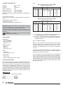 4
4
-
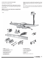 5
5
-
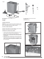 6
6
-
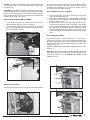 7
7
-
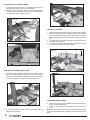 8
8
-
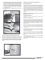 9
9
-
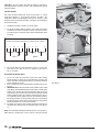 10
10
-
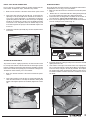 11
11
-
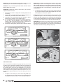 12
12
-
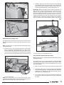 13
13
-
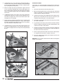 14
14
-
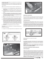 15
15
-
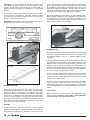 16
16
-
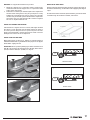 17
17
-
 18
18
-
 19
19
-
 20
20
-
 21
21
-
 22
22
-
 23
23
-
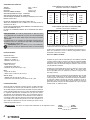 24
24
-
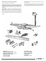 25
25
-
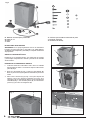 26
26
-
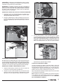 27
27
-
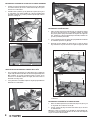 28
28
-
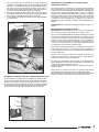 29
29
-
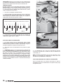 30
30
-
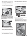 31
31
-
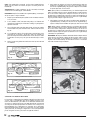 32
32
-
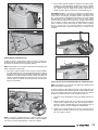 33
33
-
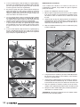 34
34
-
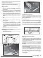 35
35
-
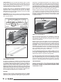 36
36
-
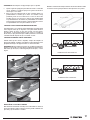 37
37
-
 38
38
-
 39
39
-
 40
40


Truper CANT-6X El manual del propietario
- Categoría
- Herramientas eléctricas
- Tipo
- El manual del propietario
Otros documentos
-
Craftsman 152.217050 El manual del propietario
-
-
DeWalt JT360 Manual de usuario
-
Powermatic 60C 8" Jointer, 2HP 1PH 230V Manual de usuario
-
Delta JT160 Manual de usuario
-
Porter-Cable PC160JT Manual de usuario
-
Craftsman CMEW020 El manual del propietario
-
Powermatic 54HH Jointer, 1HP 1PH 115/230V Manual de usuario
-
Powermatic PJ-882HH Manual de usuario
-