
ENCODER LINEAL MODELO: L3 MODULAR
LINEAR ENCODER MODEL: L3 MODULAR
MANUAL DE INSTALACION / INSTALLATION MANUAL
Manual Code: 14460290
Manual Version: 2001


L3 modular - v2001 - página / page 1 / 34
Precaución / Caution

L3 modular - v2001 - página / page 2 / 34
IG P FG FR
ML MR ID K
Instrucciones de montaje generales
General mounting instructions
Perfil cierre boca
Sealing lip
Fleje grabado
Scale tape
Flejes de rodadura (3x)
Bearing strips (3x)
Módulo izquierdo
Left module
Módulo derecho
Right module
Etiqueta de identificación
ID label
Conjunto de piezas pequeñas
Small parts set
DEFGFKG
LA
AL T J
Distanciador
Spacer
Empujador de flejes
Strips puller
Gancho para fleje de rodadura (3x)
Rolling strips hook (3x)
Kit para grasa
Grease kit
Montador de labios
Lip assembler
Pieza de amarre de labios (2x)
Lip securing piece (2x)
Dispositivo tensor
Tensioning device
Junta (recambio)
Seal (replacement)
* 25g de grasa
por bote / 25g
of grease per
tube
ELEMENTOS SUMINISTRADOS / SUPPLIED PARTS
En el KIT / in the KIT
En el conjunto de piezas pequeñas / in the small parts set
RA
Racor recto
Straight fitting

L3 modular - v2001 - página / page 3 / 34
MI
Módulo intermedio
Intermediate module
En la cabeza lectora / in the reader head
IC SC C EC
Instrucciones de montaje de cabeza
Head mounting instructions
Soporte de cabeza
Head support
Cabeza
Head
Soporte para embalaje de cabeza
Support for head packing
ACCESORIOS SUMINISTRADOS POR SEPARADO / ACCESSORIES SUPPLIED SEPARATELY
GFACAMA
Galga de montaje
Mounting gauge
Cod.: 82620204
Filtro de aire y accesorios
Compressed air filter and accesories
Cod.: 02200004
Cable y accesorios
Cable and accesories
Accesorio de montaje de cabeza
Head mounting accesory
Cod.: 82620203
Elementos suministrados por separado / Parts supplied separately
En el módulo intermedio / in the intermediate module
RA
Racor recto
Straight fitting
PG R
Protector fleje grabado
Scale tape protection
Cod.: 15m=82620205
30m=82620206
Protector fleje de rodadura
Rolling tape protection
Cod.: 82620207

L3 modular - v2001 - página / page 4 / 34
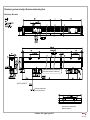
ABSOLUTA / ABSOLUTE
Dirección de contaje positiva
Positive counting direction
Modelo estándar / Standard model
Dimensiones de la unidad de módulo
Module unit dimensions
2 x M8 Cabeza ESTÁNDAR / STANDARD head
2 x M6 Cabeza OPCIONAL / OPTIONAL head
Dimensiones y opciones de montaje / Dimensions and mounting options

L3 modular - v2001 - página / page 5 / 34
1
* DIN 912 M5 DIN 912 M6
DIN 125 D5.3 & DIN 125 D6.4
Pa = 5 Nm Pa = 8 Nm
Tornillo M6 especial
Special M6 screw
Cod.: 82620163
SW 5 / Pa = 6 Nm
Nota: Resto de medidas como con la cabeza estándar
Note: Other ways, such as with a standard head
Opción cabeza con rosca M6 / Head option with M6 thread
M = Dimensión de montaje por parte del cliente
Assembly sizing set by customer
S = Dimensión de montaje alternativa por parte del cliente
Alternative assembly sizing set by the customer
C = Posibilidad de conectar a ambos lados
Can be connected to both sides
R = Posibilidad de conectar entrada de aire en ambos extremos
Can connect air intake at both ends
T = Tensor del fleje
Tape tensor
I = Comienzo de curso de medición
Beginning of measuring length
= Opciones de montaje / Mounting options
CM= Curso de medición / Measuring length
L = Longitud del módulo / Length of module
G = Guía máquina / Machine guide
Pa = Par de apriete / Tightening torque
SW= Tamaño de la llave hexagonal / Size of the hex wrench
2 3
1 2 3
1 2 3

L3 modular - v2001 - página / page 6 / 34
Con pasadores SUPERIORES / With TOP pins Con pasadores INFERIORES / With BOTTOM pins
Evitar zonas conflictivas como / Avoid problematic areas, such as:
- Uniones entre módulos / Connections between modules
- Alrededor de tornillos / Areas around bolts or screws
Montaje contra pasadores / Mounting on pins

L3 modular - v2001 - página / page 7 / 34
Las marcas triangulares del perfil definen el inicio y final del curso de medición.
Seleccionar el montaje de manera que el recorrido máximo del desplazamiento se encuentre dentro del curso de medición CM del encoder lineal.
The triangular profile marks define the start and end of the measuring length.
Select the assembly, so that the maximum travel movement is within the CM measuring length of the encoder.
Tolerancias de montaje / Mounting tolerances

L3 modular - v2001 - página / page 8 / 34
Montar con los labios de estanqueidad no orientados a posibles fuentes de contaminación.
Assemble using sealing lips that do not face any possible source of contamination.
En ambientes muy contaminantes conviene proteger el encoder lineal.
Utilizar juntas de estanqueidad para evitar filtraciones.
In very contaminated environments, it is advisable to protect the encoder.
Use sealing joints to prevent leaks.
La superficie de montaje estará libre de pintura.
The mounting surface must be paint free.
Junta
Sealing
Joint
Condiciones de montaje / Mounting conditions

L3 modular - v2001 - página / page 9 / 34
Información para el montaje y desmontaje / Information on assembly and dismantling
Guarde las protecciones, el kit de piezas pequeñas y componentes de embalado para
cuando se desmonte la máquina.
En el caso de que se desmonte recuerde que todos los elementos se utilizarán de nuevo
Store the protective covers, the small parts kit and packaging components in a safe place.
Remember that all these elements will be used again when dismantling the machine.
Retirar las protecciones / Removing the protective covers
Retirar tapas y cintas protectoras de los módulos según se montan.
Remove the protective covers and straps from the modules in the manner in which they were
mounted.
PG
Agujeros de amarre (mecanizado manual) / Fixture holes (manual machining)
Hacer los agujeros para amarrar el encoder lineal (en el caso de que no vengan mecanizados).
Drill holes to fasten the linear encoder (if they are not pre-mechanized).
Montaje / Mounting
R
K
EC
SC

L3 modular - v2001 - página / page 10 / 34
Montar el módulo ML, alinear según el dibujo y atornillar / Mount the ML module and align in accordance with the diagram and tighten the screws.
Seguir los mismos pasos con los módulos MI y MR / Follow the same steps for the MI and MR modules.
Mantener la distancia entre módulos / Ensure there is sufficient space between the modules.
* En caso de no poder montar algún módulo (paso Nº3) aflojar los últimos tornillos del módulo anterior y seguir el proceso / If a module cannot to be mounted (step No.3), then loosen the last
screws of the previous module and continue with the process.
Se recomienda utilizar el distanciador (D). Si es necesario y dentro de las tolerancias de taladro definidas, se permite una tolerancia de hasta ± 1 mm.
It is recommended that a separator (D) is used. If necessary, and within the specified drilling tolerances, a tolerance of up to ± 1 mm is allowed.
Pa = Par de apriete / Tightening torque.
* Para más opciones de montaje consultar el apartado “Dimensiones y opciones de montaje” / For other mounting options, refer to the section “Assembly sizing and options”.
D
D
Montaje de los módulos / Installation of the modules
MI
ML
MR
MI

L3 modular - v2001 - página / page 11 / 34
Insertar los flejes de rodadura / Insert the running gear straps
Insertar los ganchos (GF) en el empujador (EF) en la posición requerida.
(Los ganchos pueden ser montados los 3 a la vez o de uno en uno).
Insert the hooks (GF) into the pusher (EF) in the required position.
(Hooks can be mounted either three at a time or one at a time).
Insertar el accesorio EF por el extremo izquierdo hasta que la pestaña de referencia se sitúe
dentro del perfil.
Insert the EF accessory from the left side until the reference tab is inside the profile.
Retirar ambas tapas (tapas que vienen montadas en los módulos ML y MR).
Remove both caps (caps that come on the ML and MR modules).
EF
EF
GF x3
EF
EF
Pestaña de re-
ferencia / Ref-
erence Tab
SW 2.5
Retirar las tapas / Remove the caps

L3 modular - v2001 - página / page 12 / 34
1. Sacar el accesorio (EF) del perfil hasta que pueda ser extraído.
2. Retirar el accesorio (EF).
3. Empujar el fleje hasta introducirlo por completo dentro del perfil.
4. Después de introducir el fleje quitar el gancho (GF) utilizado.
1. Sacar el extremo del fleje de rodadura del rodete.
Pull the end of the running gear strap from the wheel.
2. Introducir el fleje en el gancho GF. Ambas caras del fleje son válidas para el montaje. (Los
flejes de rodadura pueden ser montados simultáneamente o de uno en uno).
Insert the strap into the GF hook. Either side of the strap can be used during assembly. (The
running gear strap can be mounted at the same time or one at a time).
1. Empujar el accesorio (EF) hacia el interior del encoder lineal para introducir el fleje en el perfil.
Push accessory (EF) inside the linear encoder to insert the strap into the profile.
2. Empujar el accesorio (EF) de un extremo al otro del encoder lineal.
Push the accessory (EF) from one end of the linear encoder to the other.
EF
GF
Asegurarse de que el fleje
queda dentro de la ranura.
Ensure that the strap is inside
the groove.
EF
EF
EF
EF
EF
GF
1. Remove the accessory (EF) from the profile until it can be pulled out.
2. Remove the accessory (EF).
3. Push the strip until it is fully inserted inside the profile.
4. After the strip has been inserted, remove the puller (GF).

L3 modular - v2001 - página / page 13 / 34
Insertar el accesorio EF por el extremo izquierdo hasta que la pestaña de referencia se sitúe
dentro del perfil.
Insert the EF accessory from the left side until the reference tab is inside the profile.
1. Sacar el extremo del fleje grabado del embalaje.
Observar que la posición es correcta, las pestañas tienen que estar mirando hacia arriba.
Pull the end of the scale tape from the packing.
Check that it is put the right in, the tabs have to be facing up.
2. Introducir el fleje en el empujador EF.
Insert the strip into the EF puller.
No tocar la parte grabada del fleje. No doblar el fleje.
En caso de suciedad limpiar con cuidado con un trapo que no suelte pelusa y ahcohol
isopropilico.
Do not touch the recorded scaled side of the strip. Do not bend the strip.
Carefully clean any dirt or grime using a lint-free cloth and isopropyl alcohol.
EF
EF
EF
Asegurarse de elegir el tro-
quelado correcto / Be sure to
choose the correct stamp
Insertar fleje grabado / Insert scale tape
Pestaña de re-
ferencia / Ref-
erence Tab

L3 modular - v2001 - página / page 14 / 34
Insertar el conjunto tensor / Insert the tensioning device
1. Empujar el accesorio EF hacia el interior del encoder lineal para introducir el fleje en el perfil.
2. Empujar el EF de un extremo a otro del encoder lineal hasta hacer tope con el gatillo
del lado izquierdo.
3. Empujar la pestaña hacia el exterior para desbloquear el accesorio EF.
4. Retirar el accesorio EF.
1. Introducir el conjunto tensor (T) en el extremo derecho.
2. Introducir el tensor (T) hasta que se enganche en el alojamiento del fleje.
- Si es necesario, aflojar el tornillo mientras se empuja el tensor hacia dentro hasta que
se enganche.
3. Apretar el tornillo hasta eliminar la holgura. En ese momento apretar el tornillo 5 vueltas más.
Asegurarse de que el fleje queda dentro de la ranura.
Ensure that the strap is inside the groove.
T
T
EF
EF
EF
EF
T
Tensar 5 vueltas
Tighten 5 turns
SW 3
1. Push accessory EF inside the linear encoder to insert the strap into the profile.
2. Push the EF from one end of the linear encoder to the other until it pushes against the
trigger on the left side.
3. Push the tab to the outside to unlock the EF accessory.
4. Remove the EF accessory.
1. Insert the tensioning device (T) inside the right end.
2. Insert the tensioner (T) until it locks onto the strip housing.
- If necessary, loosen the screw while pushing the tensioner in until it locks on.
3. Tighten the screw until there is no looseness. Now, tighten the screw with another 5 turns.

L3 modular - v2001 - página / page 15 / 34
1. Insertar el labio en el montador LA.
2. Insertar el labio en la ranura correcta del perfil utilizando el montador.
3. Empujar LA hasta el extremo contrario del perfil.
4. Retirar el montador LA.
A. Elegir el labio que mejor se adecue por su posición al montaje. (Uno está embalado en el
interior y el otro en el exterior). / Choose the lip best suited for its position when mounting.
(One is packed towards the inside and the other to the outside).
B. Para desembalar los labios se recomienda mover el embalaje y no tirar del labio, ya que se
puede crear una especie de espiral. / When unpacking the lips, it is recommended to move
the packing and not to pull the lip, otherwise it could cause it to spiral.
A. Cómo insertar y posicionar el montador de labios (LA) en el perfil.
How to insert and position the lip assembler (LA) into the profile.
B. Cómo colocar la cánula en el labio para aplicar grasa.
How to slide the nozzle along the lip when applying grease.
IMPORTANTE PARA LA MANIPULACIÓN DE LOS LABIOS
IMPORTANT INFORMATION WHEN HANDLING LIPS
Labio embalado
en el exterior / In-
ward packed lip
Labio embalado
en el interior / Out-
ward packed lip
A
B
CÓMO USAR LOS ACCESORIOS
HOW TO USE THE ACCESSORIES
B
A
LA
LA
Insertar 1º labio / Insert the first lip
LA
LA
LA
LA
Insertar labios / Insert lips
1. Insert the lip into the LA assembler.
2. Insert the lip into the corresponding groove along the profile using the assembler.
3. Slide the LA to the opposite end of the profile.
4. Remove the assembler LA.

L3 modular - v2001 - página / page 16 / 34
1. Insertar el labio en el montador LA.
2. Insertar el labio en la ranura del perfil utilizando el montador. (Cuidado con la posición
del primer labio insertado)
3. Empujar hasta el extremo contrario del perfil. Aplicar la grasa en el labio mientras se
introduce el labio.
1. Cortar los labios del extremo izquierdo del encoder lineal a medida.
2. Levantar los labios utilizando el montador LA. Introducir el montador por el extremo izquierdo
y mover hacia el otro extremo hasta que falten unos 200 mm para llegar al extremo derecho.
3. Cortar los labios del extremo derecho del encoder lineal a medida.
4. Terminar de levantar los labios con el accesorio LA.
Insertar 2º labio / Insert the second lip
Aplicar entre 1g y 2g de grasa
por metro / For every meter, ap-
ply between 1g and 2g of grease
KG
LA
LA
LA
LA
LA
LA
LA
1. Insert the lip into the LA assembler.
2. Insert the lip into the groove along the profile using the assembler. (Pay attention to the
position of the first inserted lip)
3. Slide to the opposite end of the profile. Apply grease to the lip as the lip is being inserted.
1. Cut the lips to size on the left side of the linear encoder.
2. Lift the lips using the LA assembler. Insert the assembler from the left side and slide it towards
the opposite side and stop around 200 mm from the right end.
3. Cut the lips to size on the right side of the linear encoder.
4. Finish lifting the lips with the LA accessory.

El montaje de la cabeza se puede llevar a cabo por ambos extremos
The mounting of the head can be done from either end.
1. Colocar el soporte (SC) en el perfil / Place the support (SC) on the profile.
2. Introducir la cabeza en el perfil / Insert the head into the profile.
1. Colocar los soportes (EC) entre cabeza y perfil. Si es posible colocar también la abrazadera
(puede ser colocada a ambos lados de la cabeza) / Place the supports (EC) between the head
and profile. If possible, also attach the clamp (it can be placed on either side of the head).
2. Atornillar los tornillos de las piezas (EC) hasta quitar la holgura (los soportes deben poder mo-
verse) / Tighten the pieces (EC) until their is no looseness (the supports must be able to move).
Quitar los soportes (EC).
Remove the supports (EC).
* Para más opciones de montaje consultar el apartado “Dimensiones y opciones de montaje”.
For other mounting options, refer to the section “Assembly sizing and options”.
Fijar la cabeza. Garantizar la distancia de 1 ± 0.3 mm en toda la longitud de medición.
Attach the head. Ensure there is a 1 ± 0.3 mm clearance along the entire length.
- Opciones / Options:
a. Con las piezas de embalaje (EC) suministradas con sus tornillos apretados.
With the supplied packing pieces (EC) and their tightened screws.
b. Con la galga de montaje (G) / With the mounting gauge (G).
c. Con el accesorio de montaje (MA) / With the assembly accessory (MA).
L3 modular - v2001 - página / page 17 / 34
SC
SC
C
C
EC
EC
EC
EC
EC
EC
Plano / Phillips
Montaje de la cabeza / Mounting the head

Colocar tapas / Put on caps
Colocar las tapas en los extremos correspondientes / Place the caps on their corresponding ends.
1. Fijar la tapa con los tornillos / Use screws to attach the cap.
2. Insertar el amarre de labios (AL) hasta el tope / Insert the lip securing piece (AL) all the way in.
3. Atornillar el prisionero hasta dejarlo al ras del perfil / Insert the set screw until it is flush with the profile.
L3 modular - v2001 - página / page 18 / 34
CONECTOR A AMBOS LADOS / TWO-SIDED CONNECTOR
Nota: Sólo conectar a un lado / Note: Only connect to one side
1. Soltar el tornillo.
2. Quitar la tapa del lado del conector: tirando (A) o haciendo palanca (B).
No quitar la tapa del lado no conectado.
Do not remove the cover on the non-connector side.
SW2.5 / Pa = 0.8 Nm
dejarlo al ras (SW2)
leave it flush (SW2)
AL
philips T10
1. Remove the screw.
2. Remove the cover on the connector side: by pulling (A) or levering (B).

L3 modular - v2001 - página / page 19 / 34
1. Realizar una comprobación de la correcta deriva a tierra del encoder lineal. El valor nominal
es: 1
max.
2. En caso de > 1
conectar el perfil a tierra. (No utilizar el tornillo de amarre de la placa de
temperatura).
Etiqueta de identificación / Identification label
Pegar la etiqueta de identificación (ID) junto a la identificación del módulo extremo izquierdo (ML).
Stick the ID label (ID) alongside the identification of the left module (ML).
ML
ID
Conexión a tierra / Ground connection
1. Verify that the ground path is correct for the linear encoder. The nominal value is: 1
max.
2. If > 1
ground the profile. (Do not use the clamping screw on the temperature plate).

L3 modular - v2001 - página / page 20 / 34
Existe la posibilidad de presurizar la cabeza lectora y el encoder lineal para minimizar la entrada
de contaminación desde el exterior. (Fagor suministra unidades de aire especificas a tal efecto).
1. Entrada de aire por ambos lados de la cabeza (extraer únicamente el tornillo del lado donde se
va a meter el aire).
2. En montajes verticales no hay que meter el aire por la parte inferior.
3. En instalaciones verticales conviene quitar el tapón de aire inferior para favorecer el drenaje.
* Material exclusivo suministrado por Fagor.
Unidades de Filtro de Aire Fagor
Fagor Air Filter Units
Cod.: 02200004
Para IP-64
For IP-64
1 bar
10 l/min.
DIN ISO 8573-1
Tamaño de particula
Particle size - (Class 1) - Max.0.1 m
Punto de rocío
Dewpoint - (Class 4) - (7 bar) 3 ºC
Contenido residual de aceite
Residual oil content - (Class 1) - 0.01 mg/m
3
SW 2.5
SW 2.5
Conexión equipo de aire / Connecting air equipment
You can pressurize the reader head and the linear encoder to reduce any contamination from en-
tering from the outside. (Fagor supplies specific air units for this purpose).
1. Air intake on both sides of the head (remove only the screw on the side where the air is going
to enter).
2. For vertical assemblies, do not run air through the bottom.
3. For vertical installations, it is advisable to remove the lower air cap to allow for drainage.
* Exclusive material supplied by Fagor.
Cod.: 82620172 *

Comportamiento térmico del encoder lineal / Thermal performance of the linear encoder
TORNILLO DE BLOQUEO = determina el tipo de comportamiento térmico del encoder lineal.
LOCK SCREW = determines the type of thermal performance of the linear encoder.
a. CLAMPED = El comportamiento térmico del encoder lineal viene definido por la bancada de la máquina / The thermal performance of the linear encoder is determined by the
machine bench.
El encoder lineal tiene el mismo coeficiente de dilatación que la bancada / The linear encoder has the same expansion coefficient as the bench.
b. UNCLAMPED = El comportamiento térmico del encoder lineal es independiente al de la máquina / The thermal performance of the linear encoder is independent of the machine
bench.
El coeficiente de dilatación lo define el fleje. [
(10
-6
ºC
-1
) = 12] / The expansion coefficient is defined by the strip. [
(10-6 ºC-1) = 12].
El punto fijo térmico se define en el extremo contrario al tornillo de bloqueo, en el punto W / The thermal fixed point is defined at the opposite end of the lock screw,
at point W.
La diferencia que se da en cuanto a las dilataciones entre el encoder lineal y la máquina debe ser compensada / The difference in dilation between the linear encoder
and the machine must be offset.
Dependiendo del tipo de comportamiento deseado elegir CLAMPED (bloqueado) o UNCLAMPED (no bloqueado, libre).
Depending on the type of desired performance, choose CLAMPED (locked) or UNCLAMPED (unlocked, free).
L3 modular - v2001 - página / page 21 / 34
W
ML
MR
Tornillo de bloqueo
Locking screw
CLAMPED
- Fleje bloqueado / Strip locked.
- Comportamiento térmico igual al de la
bancada / Thermal performance same as
bench.
UNCLAMPED
- Fleje no-bloqueado / Strip unlocked.
- Comportamiento térmico definido solo por el fleje.
Thermal performance determined only by the strip.
- Punto fijo térmico en el punto W / Thermal fixed
point at point W.
Ajuste y bloqueo de la regla / Setting and locking the encoder

Método manual: Opción 1 / Manual method: Option 1
Válido para encóderes lineales INCREMENTALES y ABSOLUTOS
1. Quitar el tapón que da acceso al tensor del fleje.
2. Situar la cabeza al final del curso de medición o lo más cerca posible.
3. Medir la distancia L (distancia entre el extremo izquierdo y el triángulo de la cabeza).
4. Calcular el valor a tensar (T) con la siguiente fórmula: T = (L - 30) x 0.00012
5. Quitar holgura al tensor. Aflojar el tornillo hasta que el indicador del visualizador se pare.
En este momento el fleje grabado está destensado, no mover más el tornillo.
6. Preseleccionar esta posición de la cabeza con el valor 0.
7. Tensar el valor T obtenido con la fórmula.
8. Definir el comportamiento térmico deseado para el encoder lineal:
a. CLAMPED: Bloquear el tornillo (Pa = 5 Nm).
b. UNCLAMPED: Tornillo desbloqueado.
9. Poner el tapón.
NOTAS:
- Los valores L y T se deben expresar en milímetros.
- Al ser un método manual puede haber errores.
L3 modular - v2001 - página / page 22 / 34
SW 3
SW 3
SW 4
Tensar valor T
Tighten to the T value
Valid for INCREMENTAL and ABSOLUTE linear encoders
1. Remove the cap to access the tape tensor.
2. Place the head at the end of the measuring length or as close as possible to it.
3. Measure the distance L (distance between the left end and the head triangle).
4. Calculate the tension value (T) by using the following formula: T = (L - 30) x 0.00012
5. Eliminate any looseness on the tensioner. Loosen the screw until the display indicator stops.
Now that the scale tape has been slackened do not turn the screw anymore.
6. Preset this head position as 0.
7. Tighten to the T value resulting from the formula.
8. Define the desired thermal performance for the linear encoder:
a. CLAMPED: Lock the screw (Pa = 5 Nm).
b. UNCLAMPED: Unlocked screw.
9. Replace the cap.
NOTES:
- The L and T values must be expressed in millimeters.
- Since this is a manual method there could be errors.

Método manual: Opción 2 / Manual method: Option 2
Válido solamente para encóderes lineales ABSOLUTOS.
(Leer el valor de la posición en el visualizador sin introducir ningún offset)
1. Quitar el tapón que da acceso al tensor del fleje.
2. Situar la cabeza al final del curso de medición o lo más cerca posible.
3. Calcular la posición V de la cabeza. (Leer en el visualizador la posición del captador sin
introducir ningún offset).
4. Calcular el valor a tensar (T) con la siguiente fórmula: T = (V - 40) x 0.00012
5. Quitar holgura al tensor. Aflojar el tornillo hasta que el indicador del visualizador se pare.
En este momento el fleje grabado está destensado, no mover más el tornillo.
6. Preseleccionar esta posición de la cabeza con el valor 0.
7. Tensar el valor T obtenido con la fórmula.
8. Definir el comportamiento térmico deseado para el encoder lineal:
a. CLAMPED: Bloquear el tornillo (Pa = 5 Nm).
b. UNCLAMPED: Tornillo desbloqueado.
9. Poner el tapón.
NOTAS:
- Los valores V y T se deben expresar en milímetros.
- Al ser un método manual puede haber errores.
L3 modular - v2001 - página / page 23 / 34
SW 3
SW 3
SW 4
Tensar valor T
Tighten to the T value
Valid only for ABSOLUTE linear encoders.
(Read the position value on the display without any offset)
1. Remove the cap to access the tape tensor.
2. Place the head at the end of the measuring length or as close as possible to it.
3. Calculate position V of the head. (Read the position of the feedback device on the display
without any offset).
4. Calculate the tension value (T) by using the following formula: T = (V - 40) x 0.00012
5. Eliminate any looseness on the tensioner. Loosen the screw until the display indicator stops.
Now that the scale tape has been slackened do not turn the screw anymore.
6. Preset this head position as 0.
7. Tighten to the T value resulting from the formula.
8. Define the desired thermal performance for the linear encoder:
a. CLAMPED: Lock the screw (Pa = 5 Nm).
b. UNCLAMPED: Unlocked screw.
9. Replace the cap.
NOTES:
- V and T values must be expressed in millimeters.
- Since this is a manual method there could be errors.

L3 modular - v2001 - página / page 24 / 34
Ajuste del encoder lineal mediante interferómetro láser / Linear encoder adjustment using laser interferometer
1. Quitar el tapón que da acceso al tensor del fleje.
2. Ajustar mediante el interferómetro láser. (El láser debe estar colocado en la zona a controlar).
Ajustar la tensión del fleje: comparar la medida que marca la cabeza con la medida que marca
el inferómetro láser y ajustar hasta que ambos coincidan.
3. Definir el comportamiento térmico deseado para el encoder lineal:
a. CLAMPED: Bloquear el tornillo (Pa = 5 Nm).
b. UNCLAMPED: Tornillo desbloqueado.
4. Poner el tapón.
Se puede realizar en toda la longitud de medición una CORRECCIÓN LINEAL DE ERRORES
hasta ±50
m/m mediante el dispositivo tensor del encoder lineal.
SW 3
SW 3
SW 4
Tensar / Tighten
Control
1. Remove the cap to access the tape tensor.
2. Adjust it using the laser interferometer. (The laser must be located in the monitoring area).
Adjust the strip tension: compare the measurement marking the head with the measurement
marking the laser interferometer and adjust until they coincide with each other.
3. Define the desired thermal performance for the linear encoder:
a. CLAMPED: Lock the screw (Pa = 5 Nm).
b. UNCLAMPED: Unlocked screw.
4. Replace the cap.
A LINEAR ERROR CORRECTION of up to ± 50 mm/m can be achieved over the entire mea-
suring length by using the linear encoder tensioning device.

Retirar el fleje grabado / Remove the scale tape
L3 modular - v2001 - página / page 25 / 34
MR
T
MR
T
ML
Gatillo
Trigger
FG
ML
FG
Gatillo
Trigger
MR
FG
T
SW 3
No dañar el fleje durante el proceso y utilizar los medios adecuados a la hora de manipular y
guardar.
1. Aflojar el tornillo del tensor (T) hasta notar holgura.
2. Empujar el tensor (T) hacia el interior del perfil (MR) para empujar el fleje grabado. (Empujar
hasta que el gatillo de sujeción del extremo contrario (ML) se pueda sacar del alojamiento
del fleje grabado (FL).
3. Mientras se empuja el gatillo del extremo izquierdo (ML), empujar el fleje (FG) hasta que el
alojamiento libre el gatillo de sujeción.
4. Tirar del tensor (T) hacia fuera y sacar el fleje grabado (FG).
Desmontaje / Dismounting
Extremar la precaución y
guardar en los embalajes
suministrados
Take extreme caution and
store in the provided
packaging
Make sure you do not damage the strip during this process and use the appropriate tools and
materials when handling and storing.
1. Loosen the tensioner (T) screw until there is some looseness.
2. Insert the tensioner (T) into the profile (MR) to push the scale tape. (Push until the holding
trigger of the opposite end (ML) can be removed from the housing of the scale tape (FL).
3. While pushing the trigger on the left end (ML), push the strip (FG) until the housing releases
the holding trigger.
4. Pull the tensioner (T) out and remove the scale tape (FG).

Modelo espejo / Mirror model
L3 modular - v2001 - página / page 26 / 34
ABSOLUTA / ABSOLUTE
2 x M8 Cabeza ESTÁNDAR / STANDARD head
2 x M6 Cabeza OPCIONAL / OPTIONAL head
Dirección de contaje positiva
Positive counting direction
Dimensiones de la unidad de módulo
Module unit dimensions
Dimensiones y opciones de montaje / Dimensions and mounting options

L3 modular - v2001 - página / page 27 / 34
Las marcas triangulares del perfil definen el inicio y final del curso de medición.
Seleccionar el montaje de manera que el recorrido máximo del desplazamiento se encuentre dentro del curso de medición CM del encoder lineal.
The triangular profile marks define the start and end of the measuring length.
Select the assembly, so that the maximum travel movement is within the CM measuring length of the encoder.
Tolerancias de montaje / Mounting tolerances

L3 modular - v2001 - página / page 28 / 34
Insertar el fleje grabado en el modelo espejo / Insert the scale tape into the mirror model
Insertar el accesorio EF por el extremo derecho del perfil hasta que la pestaña de referencia
se sitúe dentro del perfil.
Insert the EF accessory from the right side of the profile until the reference tab moves inside it.
1. Sacar el extremo del fleje grabado del embalaje.
Observar que la posición es correcta, las pestañas tienen que estar mirando hacia arriba.
Pull the end of the scale tape from the packing.
Check that it is put the right in, the tabs have to be facing up.
2. Introducir el fleje en empujador (EF).
Insert the strip into the puller (EF).
Información para el montaje del modelo espejo:
En los siguientes puntos se describen los pasos a seguir para el montaje y tensado del fleje
grabado en el modelo del encoder lineal espejo.
Para las instrucciones generales, manipulación de las tapas, montaje de módulos, montaje de
los flejes de rodadura, montaje de labios, montaje de cabeza y trabajos finales, consultar las
secciones correspondientes del montaje del encoder lineal estándar.
MR
EF
EF
Pestaña de referencia
Reference Tab
EF
Asegurarse de
elegir el troquelado
correcto / Be sure
to choose the
correct stamp
Montaje / Mounting
Information on mounting the mirror model:
The steps below must be followed for mounting and tensioning the scale tape on the mirror
linear encoder model.
For general instructions, cap handling, module mounting, bearing strip mounting, lip mounting,
head mounting and completing the installation, refer to the corresponding sections for
standard linear encoder mounting.

L3 modular - v2001 - página / page 29 / 34
1. Empujar el accesorio de montaje (EF) hacia el interior del encoder lineal para introducir el
fleje en el perfil.
2. Empujar de un extremo a otro del encoder lineal hasta hacer tope con el gatillo del lado de-
recho.
3. Empujar la pestaña hacia el exterior para desbloquear el accesorio.
4. Retirar el accesorio.
1. Introducir el conjunto tensor (T) en el extremo izquierdo.
2. Introducir el tensor (T) hasta que se enganche en el alojamiento del fleje.
Si es necesario aflojar el tornillo mientras se empuja el tensor hacia dentro hasta que se
enganche.
3. Apretar el tornillo hasta eliminar la holgura. En ese momento apretar el tornillo 5 vueltas más.
EF
EF
EF
EF
Insertar el conjunto tensor en el modelo espejo / Insert the tensioning device into the mirror model
T
T
T
SW 3
Tensar 5 vueltas
Tighten 5 turns
Asegurarse de que el fleje queda dentro de la ranura.
Ensure that the strap is inside the groove.
1. Push mounting accessory (EF) inside the linear encoder to insert the strip into the profile.
2. Push from one end of the linear encoder to the other until it pushes against the trigger on
the right side.
3. Push the tab to the outside to unlock the accessory.
4. Remove the accessory.
1. Insert the tensioning device (T) inside the left end.
2. Insert the tensioner (T) until it locks onto the strip housing.
If necessary, loosen the screw while pushing the tensioner in until it locks on.
3. Tighten the screw until there is no looseness. Now, tighten the screw with another 5 turns.

Comportamiento térmico del encoder lineal / Thermal performance of the linear encoder
L3 modular - v2001 - página / page 30 / 34
W
CLAMPED
- Fleje bloqueado / Strip locked
- Comportamiento térmico igual al de la bancada
Thermal performance same as bench
UNCLAMPED
- Fleje no-bloqueado / Strip unlocked
- Comportamiento térmico definido por el fleje
Thermal performance determined by the strip
- Punto fijo térmico en el punto W
Thermal fixed point at point W
TORNILLO DE BLOQUEO = determina el tipo de comportamiento térmico del encoder lineal.
LOCK SCREW = determines the type of thermal performance of the linear encoder.
a. CLAMPED = El comportamiento térmico del encoder lineal viene definido por la bancada de la máquina / The thermal performance of the linear encoder is determined by the
machine bench.
El encoder lineal tiene el mismo coeficiente de dilatación que la bancada / The linear encoder has the same expansion coefficient as the bench.
b. UNCLAMPED = El comportamiento térmico del encoder lineal es independiente al de la máquina / The thermal performance of the linear encoder is independent of the machine
bench.
El coeficiente de dilatación lo define el fleje. [
(10
-6
ºC
-1
) = 12] / The expansion coefficient is defined by the strip. [a (10-6 ºC-1) = 12].
El punto fijo térmico se define en el extremo contrario al tornillo de bloqueo, en el punto W / The thermal fixed point is defined at the opposite end of the lock screw,
at point W.
La diferencia que se da en cuanto a las dilataciones entre el encoder lineal y la máquina debe ser compensada / The difference in dilation between the linear encoder
and the machine must be offset.
Dependiendo del tipo de comportamiento deseado elegir CLAMPED (bloqueado) o UNCLAMPED (no bloqueado, libre).
Depending on the type of desired performance, choose CLAMPED (locked) or UNCLAMPED (unlocked, free).
Ajuste y bloqueo de la regla / Setting and locking the encoder
Tornillo de bloqueo
Locking screw

Método manual: Opción 1 / Manual method: Option 1
Válido para encóderes lineales INCREMENTALES y ABSOLUTOS
1. Quitar el tapón que da acceso al tensor del fleje.
2. Situar la cabeza al inicio del curso de medición o lo más cerca posible.
3. Medir la distancia L (distancia entre el extremo derecho del encoder lineal y el triángulo de
la cabeza).
4. Calcular el valor a tensar (T) con la siguiente fórmula: T = (L - 30) x 0.00012
5. Quitar holgura al tensor. Aflojar el tornillo hasta que el indicador del visualizador se pare.
En este momento el fleje grabado está destensado, no mover más el tornillo.
6. Preseleccionar esta posición de la cabeza con el valor 0.
7. Tensar el valor T obtenido con la fórmula.
8. Definir el comportamiento térmico deseado para el encoder lineal:
a. CLAMPED: Bloquear el tornillo (Pa = 5 Nm).
b. UNCLAMPED: Tornillo desbloqueado.
9. Poner el tapón.
NOTAS:
- Los valores L y T se deben expresar en milímetros.
- Al ser un método manual puede haber errores.
L3 modular - v2001 - página / page 31 / 34
SW 3
Tensar valor T
Tighten to the T
value
SW 3
SW 4
Valid for INCREMENTAL and ABSOLUTE linear encoders
1. Remove the cap to access the tape tensor.
2. Place the head at the start of the measuring length or as close as possible to it.
3. Measure the distance L (distance between the far right end of the linear encoder and the
head triangle).
4. Calculate the tension value (T) by using the following formula: T = (L - 30) x 0.00012
5. Eliminate any looseness on the tensioner. Loosen the screw until the display indicator stops.
Now that the scale tape has been slackened do not turn the screw anymore.
6. Preset this head position as 0.
7. Tighten to the T value resulting from the formula.
8. Define the desired thermal performance for the linear encoder:
a. CLAMPED: Lock the screw (Pa = 5 Nm).
b. UNCLAMPED: Unlocked screw.
9. Replace the cap.
NOTES:
- The L and T values must be expressed in millimeters.
- Since this is a manual method there could be errors.

Método manual: Opción 2 / Manual method: Option 2
Válido solamente para encóderes lineales ABSOLUTOS.
1. Quitar el tapón que da acceso al tensor del fleje.
2. Situar la cabeza al inicio del curso de medición o lo más cerca posible.
3. Calcular la posición V de la cabeza. (Leer en el visualizador la posición del captador sin
introducir ningún offset).
4. Calcular el valor a tensar (T) con la siguiente fórmula: T = (CM - V + 160) x 0.00012
5. Quitar holgura al tensor. Aflojar el tornillo hasta que el indicador del visualizador se pare.
En este momento el fleje grabado está destensado, no mover más el tornillo.
6. Preseleccionar esta posición de la cabeza con el valor 0.
7. Tensar el valor T obtenido con la fórmula.
8. Definir el comportamiento térmico deseado para el encoder lineal:
a. CLAMPED: Bloquear el tornillo (Pa = 5 Nm).
b. UNCLAMPED: Tornillo desbloqueado.
9. Poner el tapón.
NOTAS:
- Los valores V y T se deben expresar en milímetros.
- Al ser un método manual puede haber errores.
L3 modular - v2001 - página / page 32 / 34
SW 3
SW 3
SW 4
Tensar valor T
Tighten to the
T value
Valid only for ABSOLUTE linear encoders.
1. Remove the cap to access the tape tensor.
2. Place the head at the start of the measuring length or as close as possible to it.
3. Calculate position V of the head. (Read the position of the feedback device on the display
without any offset).
4. Calculate the tension value (T) by using the following formula: T = (CM - V + 160) x 0.00012
5. Eliminate any looseness on the tensioner. Loosen the screw until the display indicator stops.
Now that the scale tape has been slackened do not turn the screw anymore.
6. Preset this head position as 0.
7. Tighten to the T value resulting from the formula.
8. Define the desired thermal performance for the linear encoder:
a. CLAMPED: Lock the screw (Pa = 5 Nm).
b. UNCLAMPED: Unlocked screw.
9. Replace the cap.
NOTES:
- V and T values must be expressed in millimeters.
- Since this is a manual method there could be errors.

L3 modular - v2001 - página / page 33 / 34
Ajuste del encoder lineal mediante interferómetro láser / Linear encoder adjustment using laser interferometer
1. Quitar el tapón que da acceso al tensor del fleje.
2. Ajustar mediante el interferómetro láser. (El láser debe estar colocado en la zona a controlar).
Ajustar la tensión del fleje: comparar la medida que marca la cabeza con la medida que mar-
ca el interferómetro láser y ajustar hasta que ambos coincidan.
3. Definir el comportamiento térmico deseado para el encoder lineal:
a. CLAMPED: Bloquear el tornillo (Pa = 5 Nm).
b. UNCLAMPED: Tornillo desbloqueado.
4. Poner el tapón.
Se puede realizar en toda la longitud de medición una CORRECCIÓN LINEAL DE ERRORES
hasta ±50
m/m mediante el dispositivo tensor del encoder lineal.
SW 3
SW 3
SW 4
Control
Tensar
Tighten
1. Remove the cap to access the tape tensor.
2. Adjust it using the laser interferometer. (The laser must be located in the monitoring area).
Adjust the strip tension: compare the measurement marking the head with the measurement
marking the laser interferometer and adjust until they coincide with each other.
3. Define the desired thermal performance for the linear encoder:
a. CLAMPED: Lock the screw (Pa = 5 Nm).
b. UNCLAMPED: Unlocked screw.
4. Replace the cap.
A LINEAR ERROR CORRECTION of up to ± 50
m/m can be achieved over the entire mea-
suring length by using the linear encoder tensioning device.

Condiciones de garantía / Warranty terms
Declaración de conformidad / Declaration of conformity
Las condiciones de garantía de este producto están disponibles en la zona de descargas del sitio web corporativo de FAGOR.
http://www.fagorautomation.com. (Tipo de fichero: Condiciones generales de venta-Garantía).
The warranty conditions for this product are available in the downloads section of FAGOR’s corporate website at http://www.fagorautomation.com.
(Type of file: General Terms and Conditions of Purchase - Warranty).
La declaración de conformidad de este producto está disponible en la zona de descargas del sitio web corporativo de FAGOR.
http://www.fagorautomation.com. (Tipo de fichero: Declaración de conformidad).
The declaration of conformity for this product is available in the downloads section of FAGOR’S corporate website at http://www.fagorautomation.com.
(Type of file: Declaration of conformity).
L3 modular - v2001 - página / page 34 / 34


FAGOR AUTOMATION S. COOP.
Bº San Andrés Nº 19
Apdo de correos 144
20500 Arrasate/Mondragón
- Spain -
Web: www.fagorautomation.com
Email: [email protected]
Tel.: (34) 943 039 800
Fax: (34) 943 791 712
-
 1
1
-
 2
2
-
 3
3
-
 4
4
-
 5
5
-
 6
6
-
 7
7
-
 8
8
-
 9
9
-
 10
10
-
 11
11
-
 12
12
-
 13
13
-
 14
14
-
 15
15
-
 16
16
-
 17
17
-
 18
18
-
 19
19
-
 20
20
-
 21
21
-
 22
22
-
 23
23
-
 24
24
-
 25
25
-
 26
26
-
 27
27
-
 28
28
-
 29
29
-
 30
30
-
 31
31
-
 32
32
-
 33
33
-
 34
34
-
 35
35
-
 36
36
-
 37
37
-
 38
38
-
 39
39
-
 40
40


en otros idiomas
- English: Fagor L3B series User manual
Artículos relacionados
-
Fagor L3B series Manual de usuario
-
Fagor S3B series El manual del propietario
-
-
-
Fagor LA Series Manual de usuario
-
-
-
-
Fagor S2A Series El manual del propietario
-