Paslode tG100CSN Manual de usuario
- Categoría
- Herramientas eléctricas
- Tipo
- Manual de usuario

1
IMPORTANT!
DO NOT DESTROY
It is the customerʼs responsibility to have all
operators and service personnel read and
understand this manual.
OPERATING MANUAL AND
SCHEMATIC
© 2022 Illinois Tool Works Inc.
515448-1
11/22
MODEL tG100CSN
0º Coil Siding Nailer
Part# 515400

2
INTRODUCTION
®
TOOL AND FASTENER SPECIFICATIONS ................................................................. 3
SAFETY INSTRUCTIONS ............................................................................................. 4
TOOL INSTALLATION AND OPERATION ................................................................ 5-6
AIR SYSTEMS ............................................................................................................. 7-8
FEATURES AND BENEFITS .......................................................................................... 9
EXPLODED VIEW AND SPARE PARTS LIST ....................................................... 10-11
MAINTENANCE ....................................................................................................... 12-13
TROUBLESHOOTING .................................................................................................. 14
WARRANTY .................................................................................................................. 15
ACCESSORIES ........................................................................................................... 16
The Paslode tetraGRIP™ 0º
coil siding nailer is a quality-built tool designed for use
in residential siding
.
This tool will deliver
efficient, dependable performance when
used according to the
manufacturerʼs guide lines.
Please study this manual, including
the safety instructions,
to fully understand
the operation of this tool.

3
TOOL SPECIFICATIONS
MODEL NO. tG100SCN (Part# 515400)
HEIGHT 11.5”
WIDTH
LENGTH 12.25"
WEIGHT 4.9 lbs.
OPERATING PRESSURE 80 to 120 psi (5.5 to 8.3 bar)
FASTENER SPECIFICATIONS
TOOL AIR FITTINGS:
This tool uses a 3/8” N.P.T. male plug. The fitting must be capable of discharging
tool air pressure when disconnected from the air supply.
OPERATING AIR PRESSURE:
80 to120 psi (5.5 to 8.3 bar). Select the operating air pressure within this range
for best tool performance.
DO NOT EXCEED THIS RECOMMENDED OPERATING PRESSURE.
NAIL LENGTH 1.125”
SHANK DIAMETER .117 Shank
TOOL AND FASTENER SPECIFICATIONS
NAIL COATINGS Galvanized Steel, tetraGRIP™
MAGAZINE TYPE 0 Degree, Plastic Coil
6”

4
WARNING
Failure to follow any of the above instructions could result in severe personal
injury to tool user and bystanders or cause damage to tool and property.
SAFETY INSTRUCTIONS
SAFETY FIRST
These safety instructions provide information necessary
for safe operation of Paslode tools. DO NOT
ATTEMPT
TO OPERATE
THE
TOOL UNTIL
YOU READ AND
UNDERSTAND ALL SAFETY PRECAUTIONS AND
MANUAL INSTRUCTIONS.
WEAR EYE AND HEARING PROTECTION
Always wear hearing and eye protection devices, that
conform to ANSI Z87.1 requirements, when operating
or working in the vicinity of a tool. As an employer you
are responsible for enforcing the use of eye protection.
Wear hard hats in environments that require their use.
THE TOOL MUST BE USED ONLY FOR THE PUR-
POSE FOR WHICH IT WAS DESIGNED
Do not throw the tool on the floor, strike the housing in
any way or use the tool as a hammer to knock material
into place.
NEVER ENGAGE IN HORSEPLAY WITH THE TOOL
The tool is not a toy so do not use it like one. Never
engage in horseplay with the tool or point it at yourself
or any other person, even if you think it is not loaded.
NEVER ASSUME THE
TOOL IS EMPTY
Check the magazine for fasteners that may be left in the
tool. Even if you think the tool is empty or disconnected,
never point it at anyone or yourself. Unseen fasteners
could fire from the tool.
NEVER CLAMP THE TRIGGER IN A LOCKED OR
OPERATING POSITION
The trigger of the tool must never be tampered with,
disabled or clamped in a locked or operating position
since this will cause the tool to drive a fastener any
time
the work contacting element depressed.
DO NOT LOAD FASTENERS WITH THE AIR LINE
CONNECTED, OR WITH THE TOOL TRIGGER OR
WORK CONTACTING ELEMENT DEPRESSED
When loading fasteners into the tool be sure you
disconnect the air line and that you do not depress
the trigger or work contacting element.
OPERATE THE TOOL ONLY ON A WORKPIECE
The tool should be operated only when it is in contact
with the workpiece. Even then you should be careful
when fastening thin material or working near the edges
and corners of the workpiece since the fasteners may
drive through or away from the workpiece.
DO NOT DISABLE OR REMOVE THE WORK
CONTACTING ELEMENT
This tool is equipped with a safety mechanism, called a
a work contacting element, to help prevent accidental
firing. Never tamper with, disable or remove the work
contacting element. Do not use the tool unless the work
contacting element is working properly.The tool could
fire unexpectedly.
®
DISCONNECT THE TOOL WHEN NOT IN USE
Always disconnect the tool from the air line when it
is not in use, when you leave the work area or when
moving the tool to a new location. The tool must
never be left unattended because people who are
not familiar with the tool might handle it and injure
themselves or others.
CARRY THE TOOL ONLY BY THE HANDLE
Always carry the tool by the handle only. Never carry
the tool by the air hose or with the trigger depressed
since you could drive a fastener unintentionally and
injure yourself or someone else.
DO NOT WEAKEN THE TOOL HOUSING
The tool housing is a pressure vessel and should never
be weakened by having your companyʼs name, area of
work or anything else stamped or engraved into its
surface.
DISCONNECT THE TOOL WHEN PERFORMING
REPAIRS AND CLEARING JAMS
Never attempt to clear a jam or repair a tool unless you
have disconnected the tool from the air line and
removed all remaining fasteners from the tool.
ALWAYS USE THE PROPER FITTING FOR THE
TOOL
Only MALE pneumatic type air connectors should be
fitted to the tool, so that high pressure air in the tool is
vented to atmosphere as soon as the air line is dis-
connected.
NEVER install FEMALE quick disconnect couplings on
the tool. Female couplings will trap high pressure air in
the tool when the air line is disconnected, leaving the
tool charged and able to drive at least one fastener.
DO NOT EXCEED THE MAXIMUM RECOMMENDED
AIR PRESSURE
.erusserp ria dednemmocer eht ta ylno loot eht etarepO
Do not exceed the maximum air pressure marked on
the tool. Be sure the air pressure gauge is operating
properly and check it at least twice a day.
Never use any bottled air or gases such as oxygen to
operate the tool since they could cause the tool to
explode. Do not operate in explosive atmospheres such
INSPECT TOOL FOR PROPER OPERATION
.deriuqer sa etacirbul dna yliad tsael ta loot eht naelC
Never operate a dirty or malfunctioning tool.
USE ONLY PASLODE RECOMMENDED PARTS AND
FASTENERS
Use only parts and fasteners specifically designed and
recommended by Paslode
for use in the tool and for
work to be done. Using unauthorized parts and fasteners
or modifying the tool in any way creates dangerous
situations. Replace all missing warning labels---refer
to tool schematic for correct placement and part Number.
as in the presents of flammable liquids, gases, or com-
bustible dust.
®
®

5
TOOL INSTALLATION
Your Paslode tool comes ready for immediate
use and can be installed by following these steps:
1. SAFETY - All tool operators and their immediate
supervisors must become familiar with the operator
safety instructions before operating the tool. The
instructions are on page 4 of this manual.
2. Included with each tool is a copy of the operation
manual and schematic.
Keep this publication for
future reference. An ownership registration card is
also included. This card must be completed and
returned to
Paslode
immediately to register your
ownership.
3. The plastic cap in the air inlet of the tool must be
removed before the male fitting is installed. The fit-
ting must be a male pneumatic type that discharges
the air from the tool when the air line is disconnected.
4. Install a filter/regulator/lubricator unit, with a
gauge as close as practical to the tool, preferably
within ten feet. Refer to the Air Systems section of
this manual for air hose requirements and lengths.
In general, no other special installation is required.
5. If the operator is working at a bench or table,
it is usually best to run the air line underneath the
bench. A small tray under the benchtop can hold
the fastener supply and the tool when not in use.
6. If this tool does not work when it is first connect-
ed, do not try to make repairs. Call your Paslode
representative immediately.
TOOL OPERATION
Step No. 1- Grasp the nailer handle firmly with
one hand and with the other hand depress the
door latch. Swing the magazine and door open.
Loading of Nails
Step No. 2-
Remove the retaining tape from the
nail coil and place the nail coil in the magazine with
the tips of the nails against the loading tray and about
4 inches of coil unwound.
Step No. 3- Slide the free strip of nails along the
top of the feeder body assembly and feed the nails
over the feed pawls until the first nail is in the nose
raceway.
®
®
Step No. 4-
Close the magazine cover and then
the gate making sure the gate is latched securely.
®
W A R N I N G
1. Read and understand tool labels and manual.
Failure to follow warnings could result in DEATH or SERIOUS INJURY.
2. Operators and others in work area MUST wear safety glasses with side shields.
3. Keep fingers AWAY from the trigger when not driving fasteners to avoid accidental firing.
4. Know and understand what trigger system you are using. Check manual for triggering options.
5. Never point tool at yourself or others in work area.
6. Never use oxygen or other bottled gases. Explosion may occur.
TG100CSN
Coil Siding Nailer
Paslode, 155 Harlem Ave., Glenview, IL 60025
Use Paslode tetraGRIP
Studless Siding
Nails only
#650964
0.300" (7.6mm)
PATENTED tetraGRIP thread
1.125"
(29mm)
™

6
Successive (Bounce) Driving - (Orange Trigger)
■
Grasp the handle firmly.
■
Squeeze the trigger and move the tool along the work-
piece with a bouncing motion, depressing the work con-
tacting element at the points where you want to insert a
fastener.
■Keep the trigger depressed and continue to bounce the
work contacing element against the workpiece, positioning
the tool above as carefully as possible.
■When the desired number of fasteners have been driven,
release the tool trigger to avoid unintentional fastener dis-
charge.
Sequential Operation - (Gray Trigger)
The sequential operating kit prevents successive or
“bounce” driving.
■
Depress the work contacting element and hold it against
the work surface before pulling the trigger.
■
After each fastener is driven, completely release the trig-
ger and lift the tool from the work surface.
TOOL OPERATION -
continued
Use only fasteners that meet Paslode specifications.
Use of fasteners that do not meet Paslode specifica-
tions can result in damage to the tool or injury to the
operator or bystanders.
WARNING
Note:
Follow the siding manufacturerʼs instructions
when installing the nails. Always use the nail
size specified by the siding manufacturer and/
or the local building codes.
®
®
Precision Placement Driving - (Orange Trigger)
■
Grasp the tool handle firmly and hold the bottom of the
work contacting element firmly against the workpiece until
it is completely depressed.
■Squeeze the trigger to drive the fastener.
■Lift the tool from the workpiece.
■Repeat the procedure for the next fastener.
Driving of Nails
■
A
B
C
CHANGING THE TRIGGER
1. Disconnect the tool from air source.
2. Remove trigger step pin rubber retaining rings (
A ).
3. Remove trigger step pins (B).
4. Remove sequential trigger assembly
C (Gray) and spring.
5. Install Trip trigger D (Orange)
with spring and align hole and
reinsert trigger step pins.
6. Reinstall rubber retaining rings and
check for correct operation.
D
DUAL MODE
TRIGGER ACTUATION SYSTEM
FOR CONTACT ACTUATION
USE ORANGE TRIGGER.
IN THIS MODE THE TOOL WILL
CYCLE BY DEPRESSING THE
SAFETY YOKE AND THE TRIGGER.
NO SEQUENCE IS NECESSARY.
FOR SINGLE SEQUENTIAL
ACTUATION USE GREY TRIGGER.
IN THIS MODE THE TOOL WILL ONLY CYCLE
WHEN THE SAFETY YOKE IS DEPRESSED
FOLLOWED BY TRIGGER ACTUATION.
THE TOOL WILL CONTINUE TO CYCLE BY REPEATED
TRIGGER ACTUATION PROVIDED THE SAFETY YOKE
REMAINS DEPRESSED.
USE ONLY AFTER RECEIVING INSTRUCTIONS ON SAFE OPERATION.

7
AIR SYSTEMS
For air-powered tools to work their best, the air
supply system must be properly installed and
maintained regularly. A drawing in this section
shows a properly installed air supply system.
Handy checklists for installing and maintaining
air supply systems follow.
Indoor Air System Installation
-Be certain that:
•
All pipes supplying air have a large enough
inside diameter to ensure adequate air supply.
•The main supply pipe slopes down, away
from the compressor (1/16 inch per foot).
•Air storage is provided along lengthy air lines.
•Pipe line branch outlets are at the top of the
main pipe line.
•
Cutoff valves are provided at each branch
pipe line throughout the system.
•
Water legs extend from the bottom of each
branch line.
•
A refrigerant-type dryer is installed on the
system.
•
Air hoses are kept as short as practical.
•A regular maintenance program is followed.
Outdoor Air System Installation
-Be certain that:
•
A moisture trap and a filter/regulator/lubricator
are installed at the compressor.
•
Air hoses and fittings are large enough so that
air flow is not restricted. Minimum hose size is
3/8 inch ID with 1/2 inch ID hose used for any
application over 25 feet.
•Air hoses are not longer than 150 feet.
•The air system is lubricated regularly.
•A regular maintenance program is followed.
Filter/Regulator/Lubricator Units
Filter/regulator/lubricator units that can supply
enough air and protection for Paslode tools
must meet the following specifications:
•Minimum 3/8 inch NPT port size .
•50 micron or fine filters.
•Regulated pressure from zero to 120 psi.
•Lubricators designed for low or changing
airflow.
®

8
AIR SYSTEMS - Continued
Calculating Compressor Size
Use the air consumption chart in the tool
schematic for each tool when calculating
the operating requirements for the tools.
Paslode tools are designed to operate
efficiently between 80 and 120 psi and
than 120 psi.
The air consumption chart will help you find
the correct compressor size for your appli-
cation that will quickly replenish tool air
pressure.
To use the chart you will need to know how
many tools will be used and approximately
how many fasteners will be driven each
minute by each tool on the line.
Number of tools X average fasteners/minute/
tool X 1.2 (safety factor) X air consumption
(scfm) @ pressure* (psi) = scfm required.
We can use the following example:
10 tools X 30 fasteners/minute/tool X 1.2 X
0.051scfm* (@100psi) = 18.36 scfm.
*This number is found in the Air Consumption
Chart
In this example, using the air consumption
chart we find that a compressor providing
at least 19 scfm of air is required. Because
in compressors approximately 1 hp is re-
quired produce 4 scfm, a compressor of at
least 5 hp is required.
Calculated Required Piping
For example, given a 20 hp electric compressor
supplying approximately 80 cfm of air at 120 psi
and a main supply pipe length of 350 feet, we see
by the table the minimum main pipe inside diam-
eter required for this application is 1-1/4 inch.
Pneumatic System Maintenance
- Be certain that:
•Pneumatic fittings are tight and do not leak.
and ensure that automatic draining systems are
operating correctly.
• Air lines are cleared to prevent freezing,
especially in winter.
• Lubricator operation is checked regularly and
ensure it has an adequate supply of lubricant.
(Part No. 403720)
• Only regulated air is being used and that each
regulator is operating properly.
Using the equation:
®
VOLUME
OF AIR
(CFM)
LENGTH OF RUN (FT.)
NOMINAL PIPE DIAMETER (IN.)
50-200 290-500 500-1000 1000-2500 2500-5000
30-60
60-100
100-200
200-500
500-1000
1 1 1¼ 1½ 1½
1 1¼ 1¼ 2 2
1¼ 1½ 2 2¼ 2½
2 2½ 3 3½ 3½
2½ 3 3½ 4 4½
should never be operated at pressure greater
60 70 80 90 100 110 120
AIR CONSUMPTION-SCFM/FASTENER
.060
.055
.050
.040
.035
AIR PRESSURE-PSIG
.030
REFER
TO CHART
IN TOOL
SCHEMATIC

9
tG100SCN FEATURES AND BENEFITS
Comfort Grip
Ergonomic design provides
greater comfort.
Adjustable Exhaust Cap
Deflects air away
from user.
Clear View, High Capacity Magazine
Sequential Trigger
(Gray)
Lightweight
Design
4.9 Lbs.
Metal Belt Hook
No-Mar
Work Contact
Adjustable Depth of Drive

10
PARTS LEGEND tG100CSN
515400
1 502996 1 BHCS M5 x 10mm-P30 Precoat
2 502997 1 Flat Washer
3 502969 1 Air Deflector
4 511065 2
5
515447 1 Cap Casting
6
503236 1 Collar
7
502971 1 Piston Stop
8
502972 1 Main Valve Spring
* 9
503021 1 O-Ring 36.2 x 2.6mm NBR
10
515402 1 Piston, Head Valve
*11
503218 2 O-Ring 46.0 x 3.5mm NBR
12
13
502974 1 Sleeve Retainer
14
502975 1 Gasket, Top Cap
15
515404 1 O-Ring, Piston 37.7 x 3.5mm NBR
16
17
18
503220 1
*20
*21
22
24 503224 1 Roll Pin 3 x 30mm
26 1 Gasket, End Cap
27
515408 1 End Cap
30 502985 1 Spring, Trigger
28
503235 1
29
32
515411 1 Bumper
33 515413 1
34 515414 1 HEX.SOC.HD.Bolt, M4 x 8mm
35 515415 1 Flat Washer
37
515418 1 Stop Lever
515419 1
38 515420 1 Spring, Actuator
40 515422 1 Indicator
41 515423 1 Spring
42 515424 1 Pin
43
515425 1
Set Screw
503027 1
Spring Collar
47
48 515427 1 Torsion Spring
49 503240 1 O-Ring, 3.7 x 1.8mm, NBR
50 515428 1 Spring, Lever
51 515429 1 Lever
52 503251 1
53 515430 1 Feed Pawl
54 503207 2 Rolled Pin
55 515431 1 Feed Piston
56 515432
1
57 515433 1
58 503210 1
Torsion Spring, Door
59 503212 1
Lower Work Contact Element
61 515434 1 PU Ring
62 515435 1 Tail Pawl
63 502989 1 Rubber Washer
64 515436 1 Spring
65 515437 1 Door
66 515438 1 Stepped Pin
67
68 502999 1
69 503203 1 Straight Pin
70 503241 4 Hex.SOC.HD.Bolt M6 x 20mm
19 502978 1 Sleeve Bulkhead Seal
72 515441 1
Rubber No Mar Contact Tip
73
515440 1 Magazine Assembly
74
60 503243 1
C Ring, 24mm
23
502981
* Denotes Normal Wear Items
**
Make sure Warning Label (Part No.515441)
is properly affixed. Replace if necessary.
▲ Apply Loctite 242 (Blue) Part N o. 093500
Denotes New Change
WARNING
All parts must be periodically inspected and replaced if
worn or broken. Failure to do this can affect the toolʼs
operation and present a safety hazard.
AIR CONSUMPTION CHART
AIR CONSUMPTION-CFM FASTENER
AIR PRESSURE-PSIG
25
31
36
515416 1 Contact Arm Cover
71
515443 2
.090
.080
.050
.060
.070
120
.030
.040
11010090807060
➔
**
.048
515409 1
Lock Nut, M5
S.H.C.S. M5 x 12mm
Hex.S0C.HD.Bolt, M5 x 10mm
Stopper, Flat Spring
Flat Washer, 4.0 x 10mm
O-Ring, 9.0 x 2.0mm,MBR
O-Ring, 17.9 x 2.5mm, NBR
Compression Spring
Feed Piston Stop
Warning Label
515442 1
515439 1 Sleeve
tetraGRIP™ 0º Coil Siding Nailer
▲
▲
®
.
*
*
*
*
45
515426 1
Stopper
*
*
515446 1 Lock Washer
*
46
Wave washer, 41 x 52mm
503252 1 O-Ring 39.7 x 3.5mm NBR
*
502998 8 Hex.SOC.HD.Bolt, M5 x 20mm
*
*
503246 1
O-Ring 47.3 x 2.6mm NBR
*
503222 2 O-Ring 1.9 x 1.9mm NBR
502980 2 Pin, Trigger
503233 1 Roll Pin 3 x 20mm
*
515406 1 O-Ring 72 x 3.0 NBR
502983 1 Belt Hook
▲
44
515445 1 Hex.SOC.HD.Bolt, M4 x 10
*
*
39 515421
1 Actuator
O-Ring 45.7 x 2.6mm NBR
75 515551 1
Label, Magazine
76 515550 1
Label, Trigger Operation

MODEL tG100CSN
Part# 515400
tetraGRIP™
Coil Siding Nailer
CAP ASSEMBLY
515401
DRIVER
ASSEMBLY
515403
BODY
W/THREAD
INSERTS
515407
CYLINDER
ASSEMBLY
515405
TRIGGER
VALVE
ASSEMBLY
515410
DEPTH OF DRIVE
ASSEMBLY
502993
NOSE
ASSEMBLY
515417
UPPER WORK
CONTACT ASSY.
515412
ADJ. SAFETY
TIP ASSY.
515444
SEQUENTIAL
TRIGGER
ASSY.
503055
OPTIONAL
TRIP FIRE
TRIGGER
ASSEMBLY
(ORANGE)
502986
(GRAY)
10
1
2
3
4
5
9
8
7
6
10
21
22
25
26
24
23
19
18
17
16
15
14
13
12
11
20
5 27
28
29
72
74
71
30
3334
35
36 3738 39 40 41
42
43
44
45
46 47
48
54
49
56
31
57
58 59 60
66
61
62
51
70
32
73
69
64
55
53
52
65
63
26
67
68
74
50
75
DUAL MODE
TRIGGER ACTUATION SYSTEM
FOR CONTACT ACTUATION
USE ORANGE TRIGGER.
IN THIS MODE THE TOOL WILL
CYCLE BY DEPRESSING THE
SAFETY YOKE AND THE TRIGGER.
NO SEQUENCE IS NECESSARY.
FOR SINGLE SEQUENTIAL
ACTUATION USE GREY TRIGGER.
IN THIS MODE THE TOOL WILL ONLY CYCLE
WHEN THE SAFETY YOKE IS DEPRESSED
FOLLOWED BY TRIGGER ACTUATION.
THE TOOL WILL CONTINUE TO CYCLE BY REPEATED
TRIGGER ACTUATION PROVIDED THE SAFETY YOKE
REMAINS DEPRESSED.
USE ONLY AFTER RECEIVING INSTRUCTIONS ON SAFE OPERATION.
76

12
MAINTENANCE
Paslode® tools are built for ease of maintenance. A few
simple details will assure trouble-free operation and long
tool life. Anyone who uses or maintains the tool must read
the safety and maintenance instructions. Study the sche-
matic drawing before starting any repairs on the tool.
Air-operated tools must be inspected periodically, and worn
or broken parts must be replaced to keep the tool operating
safely and efficiently. Also the items on the maintenance
chart must be checked often.
Cold Weather Care
When temperatures are below freezing, tools should be
kept warm by any convenient, safe method. If this is not
possible, the following procedure should be used to warm
up the tools.
❑ Reduce the regulated air pressure to 30 psi.
❑ Remove all fasteners from the tool.
❑
Collect an air line and blank fire the tool. The reduced
air pressure will be enough to free-
fi
re the tool. Slow speed
operation tends to warm up the moving parts. Slowing up
the piston helps the bumper and the O-rings to become
springy.
❑ Once the tool is warmed up, readjust the regulator to
the proper working pressure and reload the tool.
❑
Tool operators working outdoors or in unheated areas
in extremely cold temperatures should also:
Use Paslode pneumatic oil with antifreeze in the
lubricator, Part No. 219090 (8oz.)
Once a week, depending on the amount of tool
use, take the tool apart and wash away any sludge
with tool cleaner (Paslode Part No. 219348) to
keep the tool operating efficiently.
Cleaning the air-operated tools with solvents removes the
thin coating of grease applied to the cylinder wall and
O-rings at the factory. To replace this coating of grease,
use Chemplex grease (Paslode Part No. 403734).
❑
Open the drain on the air compressor tank to drain any
moisture at least daily in extremely cold or humid weather.
A few ounces of anti-freeze in the tank will keep the air
free of frost.
Testing the Tool After Servicing
After replacing any part or parts, it is important to check
the tool for proper operation. This ensures that the tool
was put together correctly, is safe to use, and will perform
the job properly.
❑ Ensure that all hardware is tight.
❑
Ensure that the work contacting element is installed
correctly in relation to the trigger, and that both parts move
freely.
❑ Ensure that the magazine is properly attached.
❑
Ensure that the required safety information on the tool
is legible.
❑
Use only Paslode approved fasteners in the tool, and
ensure that they are correct for the application.
❑
Ensure that a male air fitting is securely connected to
the tool.
❑
Test the tool by driving fasteners into a workpiece iden-
tical to the tool's application.
❑
Check the tool for air leaks during testing and for the
proper sequence of operation.
❑
Ensure that all fasteners are driven to the same depth
and that the crown of the fastener is flush with the work-
piece.
Tool Lubrication
It is most important that the tool be properly lubricated by
keeping the air line lubricator filled and correctly adjusted.
Without proper lubrication the tool will not work properly
and parts will wear prematurely.
Use the proper lubricant in the air line lubricator. The
lubricator should be of low air
flow or changing air flow
type, and should be kept
filled to the correct level. Use
only Paslode recommended lubricants. Substitutes may
harm the rubber compounds in the tools O-rings and other
rubber parts. Paslode Part No. 403720 is a pneumatic
lubricating oil specially made for pneumatic applications.
If a filter/regulator/lubricator is not installed on the air sys-
tem, air operated tools should be lubricated at least once
a day with 6 to 20 drops of oil, depending on the work
environment, directly through the male fitting in the tool
housing.
Most minor problems can be resolved quickly and easily
using the maintenance table that follows. If problems per-
sist, contact your Paslode dealer for assistance.

13
MAINTENANCE - Continued
Drain air line filter(daily).
Keep lubricator filled.
Clean filter element-then blow
air through filter in direction
opposite to normal flow.
Check that all screws on tool
are tight.
Keep work contacting element
working properly.
Keep magazine and feeder
mechanism clean.
Lubricate "O" rings that are
replaced.
Use only Paslode replacement
parts.
ACTION
WHY
HOW
MAINTENANCE TABLE
Prevent accumulation of
moisture and dirt.
Keep tool lubricated.
Prevent clogging of filter with
dirt.
Prevent air leakage and pro-
mote efficient operation.
Promote operator safety and
efficient tool operation.
Prevent jamming of fasteners.
Assure long life and proper
operation of tool.
Keep tool operating efficiently
and maintain Paslode tool
warranty.
Open manual petcock (most
air supply systems have such
a valve).
Fill with pneumatic tool
lubricant. Part No. 403720.
Wash with soap and water or
follow manufacturers instruc-
tions.
Check screws daily.
Blow clean daily.
Blow clean daily.
Use Chemplex grease, Part
No. 403734.
Order any repacement parts
needed from Paslode Dealer.
Check the driver blade regularly
and replace when worn.
Ensure proper operation of the
tool.
Remove piston and driver
assembly from tool and com-
pare with new driver blade.
Replace when worn.
®
®
®®
CAUTION
Disconnect the tool when performing
repairs or clearing jams.

14
OPERATOR TROUBLESHOOTING
PROBLEM CORRECTIVE ACTION
Fasteners will not drive completely into wood.
Fasteners penetrate properly during normal
operation, but won't drive fully at faster speeds.
Fasteners drive too deeply into wood.
Tools skips during operation - no fasteners are
driven from time to time.
Tool operates, but no fasteners are driven.
Air leaks at cap when tool is connected to air.
Increase air pressure (do not exceed 120 psi).
Increase air flow to tool -- use larger air lines
(3/8 inch ID minimum).
Reduce air pressure.
Inspect check and feed claw for wear and proper
operation.
Clean as needed to remove debris.
Make sure correct fasteners are being used.
Use fasteners that meet Paslode
only.
®specifications
Increase air flow to tool -- use larger air lines
(3/8 ID minimum).
Check magazine for proper fasteners.
Increase air pressure (do not exceed 120psi).
Tighten capscrews.
CAUTION
Disconnect the tool when performing
repairs or clearing jams.
14

15
An Illinois Tool Works Company
155 Harlem Avenue
Glenview, IL 60025
TOOL WARRANTY AND LIMITATIONS
TOOL WARRANTY
P
WARRANTY STATEMENT
This warranty is limited to tools sold and service requested
in the United States. To obtain information on warranty
service in the United States, refer to the Service Center
listing that was provided with your tool.
Paslode's sole liability hereunder will be to replace any part
or accessory which proves to be defective within the specific
time period. Any replacement part or accessory provided in
accordance with this warranty will carry a warranty for the
balance of the period of warranty applicable to the part it
replaces. This warranty does not apply to part replacement
required due to normal wear.
This warranty is void as to any tool which has been subjected
to misuse, abuse, accidental or intentional damage, use with
fasteners,not meeting Paslode specification, size, or quality,
repaired with other than genuine
damaged in transit or handling, or
has been altered or repaired in a
from the performance of the tool.
PASLODE MAKES NO WARRANTY, EXPRESSED OR
IMPLIED, RELATING TO MERCHANTABILITY, FITNESS, OR
OTHERWISE, EXCEPT AS STATED ABOVE, and Paslode's
liability AS STATED ABOVE AND AS ASSUMED ABOVE is
in lieu of all other warranties arising out of, or in connection
with, the use and performance of the tool, except to the extent
other wise provided by applicable law. PASLODE SHALL IN
NO EVENT BE LIABLE FOR ANY DIRECT, INDIRECT, OR
CONSEQUENTIAL DAMAGES, INCLUDING, BUT NOT
LIMITED TO, DAMAGES WHICH MAY ARISE FROM LOSS
OF ANTICIPATED PROFITS OR PRODUCTION, SPOILAGE
OF MATERIALS, INCREASED COST OF OPERATION, OR
OTHERWISE.
improperly maintained,
Paslode replacement parts,
which, in Paslode's opinion,
way that affects or detracts
MODEL tG100SCN
tetraGRIP™Coil Siding Nailer
Paslode reserves the right to change specifications, equipment, or
designs at any time without notice and without incurring obligation.
Paslode warrants that newly purchased power
fastening tools, parts and accessories will be free
from defects in material and workmanship for the
period shown below, after the date of delivery to
the original user.
ONE-YEAR FULL WARRANTY
A one-year warranty will apply to all parts.
FIVE-YEAR EXTENDED LIMITED WARRANTY
A five-year warranty will apply to all housing and
cap assembly castings.

Lubricants and Loctite
Loctite 242 (Blue) Part No. 093500
Lubricating Oil 16 oz. Part No. 403720
Lubricaing Oil with Antifreeze 8 oz. Part No. 219090
Chemplex 710 Lubricant 1lb. Part No. 403734
Tool Cleaner
Ideal cleaner for all Paslode tools. Part No. 219348
Safety Glasses
Clear Part No. 401382
ACCESSORIES
®
®
Lubricant 5 gram tube
Part No. 219188
PASLODE is a registered trademarks of ITW. tetraGrip™ is a trademark of ITW.
All other trademarks are property of their respective owners.
®
®
®
P
An Illinois Tool Works Company
155 Harlem Avenue
Glenview, IL 60025
For additional information on Paslode products, visit our website at
www.paslode.com.
For technical support call 1-800-222-6990.
To purchase parts and accessories, visit www.itwconstructionparts.com.
®

17
¡IMPORTANTE!
NO DESTRUYE ESTE MANUAL
El cliente tiene la responsibilidad de que todo
el personal de operaciones y servicio lea y
entienda este manual.
Manual de Funcionamiento y
Esquema
0 º
Bobina Siding Clavadora
Pieza# 515400
MODELO TG100CSN

18
INTRODUCCIÓN
CONTENIDO
SPECIFICACIONES DEL LA HERRAMINETA Y SUS SUJETADORES.............................3
INSTRUCCIONES DE SEGURIDAD................................................................................... 4
INSTALACION Y OPERACION DE LA HERRAMINETA..................................................5-6
SISTEMAS DE AIRES.......................................................................................................7-8
BENEFICIOS DE LA HERRAMIENTA................................................................................ 9
VISTA EXPANDIDA CON LISTADO DE PIEZAS..........................................................10-11
MANTENIMIENTO.........................................................................................................12-13
DETECCION Y CORRECION DE FALLAS........................................................................14
GARANTIA.........................................................................................................................15
ACCESORIOS....................................................................................................................16
2
El Paslode tetraGRIP ™ 0º clavadora bobina de revestimiento es una herramienta integrada de
calidad diseñado para su uso en el revestimiento residencial. Esta herramienta entrega eficiente,
confiable desempeño cuando se utiliza de acuerdo con las directivas del fabricante.
Por favor este manual de estudio, incluyendo las instrucciones de seguridad, para comprender el
funcionamiento de esta herramienta.

19
ESPECIFICACIONES DE LA HERRAMIENTA
NO. de MODELO tG100SCN (Part# 515400)
ALTURA 11.5”
ANCHO 6"
LONGITUD 12.25"
PESO 4.9 lbs.
PRESIÓN de OPERACIÓN 80 hasta 120 psi (6.2 hasta 8.3 bar)
TIPO de CARGADOR 0 Grados, en Coil, de plástico
ESPECIFICACIONES de los SUJETADORES
ACOPLAMIENTO DE AIRE:
Esta herramienta utiliza un tapón macho de 3/8" N.P.T. El acoplamiento debe ser
capaz de
descargar la presión de aire en la herramienta cuando sea desconectada
del suministro de aire.
OPERACION de PRESIÓN de AIRE:
90 hasta120 psi (6.2 hasta 8.3 bar). Seleccione una presión de aire dentro de esta
gama para obtener el mejor rendimiento.
NO EXCEDA LA PRESIÓN DE AIRE RECOMENDADA.
LONGITUD DEL CLAVO 1.125”
DIAMETRO DEL TALLO .117
ESPECIFICACIONES DE LA HERRAMIENTA Y LOS SUJETADORES
3
ACABADOS DEL CLAVO acero galvanizado, tetraGRIP™

20
PELIGRO
La falta de observación de cualquiera de estas instrucciones puede ser causa de graves
lesiones personales, tanto al operador de la herramienta comoa quienes estén cerca de
ella o de daños materiales o a la herramienta.
LA SEGURIDAD ESTA PRIMERO
Estas instrucciones proporcionan la información necesatia para el
funcionamiento sin peligrode las herramientas Paslode .
NO trate
de usar su herramienta hasta que no haya léido y entendido
todas las precauciones de seguridad y las instrucciones de
este manual.
PROTEJASE LOS OJOS Y LOS OIDOS
Use siempre el equipo adecuado para protegerse los ojos y los
oídos que sea conforme con ANSI Z87, meintras usa una her-
ramienta o trabaja cerca de una herramienta en uso. Como em-
pleador usted es responsable de imponer el usp del la porteccion
de ojo. Lleve sombreros duros en los ambientes que requieren
su uso.
USE SU HERRAMIENTA SOLAMENTE PARA EL
PROPOSITO CON QUE FUE DISEÑADA
No arroje la herramienta al suelo; no golpee el armazón ni la use
como un martillo.
NUNCA USE LA HERRAMIENTA PARA JUGUETEAR
Esta herramienta no es un juguete; por lo tanto no la trate como
tal. Nunca juguetee con ella, ni se apunte a usted mismo ni a otra
persona, aun cuando crea que no está cargada.
NUNCA ASUMAQUE LA HERRAMIENTA ESTA VACIA
Verfique que ho haya sujetadores en elcargador. Aun cuando crea
que está vacía o desconectada, nunca se apunte ni apunte a otra
persona con la herramienta, porque podría dispararse un sujetador
que no esté a la vista.
NUNCA SUJETE EL GATILLO EN LA POSICION DE
CIERRE O DE FUNCIONAMIENTO
Nunca se debe manipular indebidamente o dejar inoperante el
gatillo, o sujetarlo en la posición de cierre o defuncionamiento,
porque se podría disparar un sujetador al oprimirse el elemento
de contacto.
NO CARGUE SUJETADORES CUANDO LA LINEA DE
AIRE COMPRIMIDO ESTE CONECTADA, O CUANDO
EL GATILLO O EL ELEMENTO DE CONTACTO ESTE
OPRIMIDO.
Antes de cargar sujetadores en la herramienta, verifique que la
línea de aire comprimido esté desconectada y que ni el gatillo ni
el elemento de contacto estén oprimidos.
USE LA HERRAMIENTA SOLAMENTE SOBRE UN MA-
TERIAL DE TRABAJO
La herramienta debe funcionar sólo cuando esté en contacto con el
material de trabajo. Debe tener mucho cuidado cuando el material
sea delagado o trabaje cerca de las aristas del mismo, porque los
sujetadores podrían atravesar o salirse del material.
NO DEJE INOPERANTE NI QUITE EL ELEMENTO DE
CONTACTO
Esta herramienta está equipada con un mecanismo de seguridad,
llamado elemento de contacto, para prevenir cualquier disparo
accidental. Nunca manipule indebidamente, deje inoperante, ni
quite el elemento de contacto. No use la herramienta a menos que
dicho elemento funcione correctamente, porque podría producirse
un disparo imprevisto.
DESCONECTE LA HERRAMIENTA CUANDO NO LA
ESTE USANDO
Siempre desconecte la herramienta de la línea de aire comprimdo
cuando no la esté usando o al dejar su lugar de trabajo. Nunca la
descuide, porque cualquier persona que no esté familiarizada con
ella podría lastimarse o lastimar otros.
TOME LA HERRAMIENTA SOLAMENTE POR EL
MANGO
Siempre tome la herramienta sólo por el mango. Nunca la tome
por la manguera o con el gatillo oprimido, porque se podría
disparar un sujetador y herirlo o herir a otra persona.
NO ALTERE EL ARMAZON DE LA HERRAMIENTA
El armazón de la herramienta es un recipiente a presión y nunca se
debe grabar en su superficie el nombre de su compañia, el del área
de trabajo, ni ningún otro detalle.
DESCONECTE LA HERRAMIENTA PARA HACER
REPARACIONES O ELIMINAR OBSTRUCCIONES
Nunca trate de eliminar obstrucciones o reparar una herramienta
sin haberla desconectado de la línea de aire compromido y quitado
todos los sujetadores.
USE SIEMPRE LOS ADAPTADORES APROPIADOS
PARA SU HERRAMIENTA
Se debe conectar a la herramienta solamente conectores neumáticos
MACHOS, para permitir que el aire de alta presíon salga tan pronto
como se desconecte la línea de aire comprimido.
NUNCA coloque enlaces HEMBRAS de desconexíon rápida en la
herramienta, porque atrapan el aire a alta presíon al desconectar
la línea de aire comprimido, dejándola cargada y lista para disparar
por lo menos un sujetador.
NO EXCEDA LA PRESION NEUMATICA MAXIMA
RECOMENDADA
La herramienta debe funcionar sólo con la presíon neumática
recomendada. No exceda la presíon neumática máxima marcada
en la herramienta. Verifique por lo menos dos veces al día que el
calibre de la presíon neumática funcione correctamente.
Nuna use aire o gases envasado, como el oxígeno, para hacer
inflamables, gases o polvo combustible.
INSPECCIONE LA HERRAMIENTA PARA LA
OPERACION APROPIADA
Limpie diariamente la herramienta y lubríquela como se recom-
ienda. Nunca trate de hacer funcionar una herramienta sucia o
defectuosa.
USE SOLAMENTE PIEZAS Y SUJETADORES
RECOMENDADOS POR PASLODE
Use sólo piezas y sujetadores específicamente diseñados y
recomendados por Paslode para usar con esa herramienta y para
la tarea requerida. Si se usan piezas o sujetadores no autorizados
o se modifica de alguna forma la herramienta, se pueden crear
situaciones peligrosas. Vuelva a colocar todas las etiquetas de
precaucíon que flaten. Consulte el diagrama de la herramienta sobre
el número de cada parte y su ubligación correcta.
®
opere en atmósferas explosivas como en presencia de líquidos
funcionar la herramienta porque podrían hacer que explotara. No
INSTRUCCIONES DE SEGURIDAD
4
®
®

5
INSTALACION DE LA
HERRAMIENTA
Su herramienta Paslode está lista para usarse y
se puede unstalar siguiendo estos pasos:
1. SEGURIDAD:
Antes de usar la herramienta, todos
los operadores y sus supervisores inmediatos deben
familiarizarse con las instrucciobnes de seguridad de
la página 4 de este manual.
2. Con cada herramienta se entrega una copia de este
manual. Conserve este manual para cualquiera
consulta
futura. Además, se incluye una targeta de rehistro, que
debe llenarse y devolverse inmediatamente a Paslode
para que su herramienta quede registrada.
3. Quite la cubierta plástica en la entrada del aire de la
herrmienta antes de instalar el adaptador macho. Se
requiere un adaptador neumático tipo macho, que desc-
argue el aire de la herramienta cuando se desconecte
la línea de aire comprimido.
4. Instale una unidad de filtro/regulador/lubricador con
un calibre, tan cercano al de la herramienta como sea
posible, de preferencia a menos de tres metros. Con-
sulte le sección Sustemas Neumáticos de este manual
sobre la longitud y los requisitos de las mangueras de
aire comprimido. En general, no se exige ninguna otra
instalación especial.
5. Si el operador usa una mesa para trabajar. se acon-
seja colocar la línea de aire comprimido debajo de la
misma. Se puede colocar una pequeña bandeja en la
parte inferior de la mesa para quardar los sujetadores
y la herramienta cuando no están un uso.
6. Si la herramienta no funciona cuando se conecta por
primera vez, no trate de repararla; llame de inmediato
al representate de Paslode.
PELIGRO
La presión de aire en la herramienta nunca
debe exceder 120 psi.
FUNCIONAMIENTO DE LA
HERRAMIENTA
®
®
®
Clavadora de Rollo de clavos
Paso 1:
Sujete firmemente la clavadora manejar con
una mano y con la otra mano bajar el pestillo de la
puerta. Swing, la revista y la puerta abierta.
Paso 2:
rollo en el cargador, de modo que la punta de los clavos
se
apoye en la bandeja, teniendo unos 10 cm de clavos
desen rollados.
Paso 3:
superior del cuerpo del alimentador de reunión y el
primer lugar entre las uñas y garra la alimentación
en la nariz raceway.
Quite el retén de un rollo de clavos y coloque el
Deslice la banda libre de clavos en la parte
W A R N I N G
1. Read and understand tool labels and manual.
Failure to follow warnings could result in DEATH or SERIOUS INJURY.
2. Operators and others in work area MUST wear safety glasses with side shields.
3. Keep fingers AWAY from the trigger when not driving fasteners to avoid accidental firing.
4. Know and understand what trigger system you are using. Check manual for triggering options.
5. Never point tool at yourself or others in work area.
6. Never use oxygen or other bottled gases. Explosion may occur.
TG100CSN
Coil Siding Nailer
Paslode, 155 Harlem Ave., Glenview, IL 60025
Use Paslode tetraGRIP
Studless Siding
Nails only
#650964
0.300" (7.6mm)
PATENTED tetraGRIP thread
1.125"
(29mm)
™
Solo use clavos que reunan las especificaciones de
Paslode.
El uso de clavos que no reunan las especificaciones de
Paslode puede resultar en daños a la herramienta o
causar lesiones personales al operador o a quienes
estén cerca de ella.
No mezcla diferentes tamaños de clavos dentro del
cargador a la misma ves.
Quite todos los clavos antes de cambiar a clavos de otro
tamaño.
ADVERTENCIA
®
®

6
FUNCIONAMIENTO DE LA HERRAMIENTA
(Continuación)
El uso de clavos que no reunan las especificaciones de
estén cerca de ella.
cargador a la misma ves.
tamaño.
ADVERTENCIA
NOTA:
locales.
®
®
Impulsos sucesivos (de robote) (Gatillo Naranjado)
en los lugares donde quiera colocar un sujetador.
Manteniendo apretado el gatillo, continúe hacien-
herramienta, como se indica más arriba.
que salgan más.
Impulsó de Clavos
Colocación precisa (Naranjado)
Tome firmemente la herramienta por el mango y
de trabajo.
Apriete el gatillo para disparar el sujetador.
Separe la herramienta del material de trabajo.
sujetador.
PELIGRO
No sujete ni sostenga el gatillo con ninguna
otra cosa que no sea la mano.
Funcionamiento en secuencia (Gatillo Gris)
Con el gatillo gris elfuncionamiento en secuencia evita
los impulsos sucesivos o “de rebote”
Oprima el elemento de contacto y manténgalo
apoyado contra el material de trabajo antes de
apretar el gatillo.
Después de haber impulsado cada clavo, suetar
completamente el gatillo y levante la herramienta
del material de trabajo.
CAMBIO DEL GATILLO
1. Desconecte la herramienta de la fuente de aire.
2. Retirar el anillos de retención de goma del pasador
del gatillo ( A).
3. Retire el pasador de paso gatillo (B).
4. Retire el ensamble del gatillo secuencial
(gris) y el resorte ( C ).
5. Instale el disparador de disparo (D)
(naranja) con resorte y alinee el orificio
y vuelva a insertar el pasador del paso del
gatillo.
6.
Vuelva a instalar el anillos de retenión de caucho
y compruebe su correcto funcionarniento.
Siga las instrucciones del fabricante de conectores
metálicos cuando instale los clavos. Siempre use el
tamaño de clavo especificado por el fabricante de
conectores metálicos y/o los códigos de edificación
Solo use clavos que reunan las especificaciones de
Paslode .
Paslode puede resultar en daños a la herramienta o
causar lesiones personales al operador o a quienes
No mezcla diferentes tamaños de clavos dentro del
Quite todos los clavos antes de cambiar a clavos de otro
Apriete el gatillo y mueva la herramienta a lo
Tome la herramienta firmemente por el mango.
largo del material de trabajo con un movimiento
de robote, oprimiendo el elemento de contacto
do rebotar el elemento de contacto contra el ma-
terial de trabajo, colocando cuidadosamente la
Una vez que haya colocado todos los sujetadores
necesarios, deje de oprimir el gatillo para evitar
sosténgala de modo que la base del elemento
de contacto quede bienapoyada en el material
Repita el mismo procedimiento con el próximo
A
B
C
D
DUAL MODE
TRIGGER ACTUATION SYSTEM
FOR CONTACT ACTUATION
USE ORANGE TRIGGER.
IN THIS MODE THE TOOL WILL
CYCLE BY DEPRESSING THE
SAFETY YOKE AND THE TRIGGER.
NO SEQUENCE IS NECESSARY.
FOR SINGLE SEQUENTIAL
ACTUATION USE GREY TRIGGER.
IN THIS MODE THE TOOL WILL ONLY CYCLE
WHEN THE SAFETY YOKE IS DEPRESSED
FOLLOWED BY TRIGGER ACTUATION.
THE TOOL WILL CONTINUE TO CYCLE BY REPEATED
TRIGGER ACTUATION PROVIDED THE SAFETY YOKE
REMAINS DEPRESSED.
USE ONLY AFTER RECEIVING INSTRUCTIONS ON SAFE OPERATION.

23
7
SISTEMAS NEUMÁTICOS
El sistema neumático debe estar correctamente
instalado y recibir mantenimiento periódicamente para
que todas las herramientas de potencia neumática
funcionen bien. El diagrama de más abajo muestra
un sistema neumático correctamente instalado. A
continuación se detallan las revisiones necesarias
para la instalación y el mantenimiento de los sistemas
neumáticos.
Instalación de Un Sistema Neumático
para Interiores
- Asegure Que:
■
El diámetro interior de todas las líneas que
suministran aire sea bastante grande como para
garantizar un suministro de aire adecuado.
■ La línea principal tenga una inclinación de (1/16
de pulgada por pie) a partir del compressor.
■
Existen almacenamientos de aire a lo largo de las
líneas muy largas.
■
Las salidas de aire en las líneas secundarias
estén en la parte superior de la línea principal.
■
Existen válvulas de cierre en cada una de las
líneas secundarias de todo el sistema.
■
Las columnas de agua se extiendan desde el
extremo inferior de cada línea secundaria.
■ Se haya instalado en el sistema un secador tipo
refrigerante.
■
Las mangueras de aire sean tan cortas como sea
posible.
■
Se siga un programa regular de mantenimiento.
Instalación de Un Sistema Neumático
para Exteriores
- Asegure Que:
■ Se hayan instalado en el compresor un colector
de humedad y un filtro/regulador/lubricador.
■
Las mangueras de aire y los adaptadores tengan
la longitud suficiente para que el aire circule sin
problemas. El diámetro mínimo de una manguera
de aire es de 3/8 de pulgada y de 1/2 pulgada
para cualquier aplicación de más de 7.60 m.
■ Las mangueras de aire no midan más de 45.70 m
de longitud.
■ El sistema neumático sea lubricado
periódicamente.
■
Se siga un programa regular de mantenimiento.
Unidades de Filtro/Regulador/Lubricador
Las unidades de filtro/regulador/lubricador capaces
de proporcionar aire y protección suficientes a las
herramientas Paslode deben tener las siguientes
características:
■
Tamaño mínimo del orificio a presión y tempera
tura normales de 3/8 de pulgada
■ Filtros de 50 micrones o más finos
■ Presión regulada de 0 a 120 psi
■
Lubricadores diseñados para corriente de aire
baja o variable
SISTEMAS NEUMATICOS
Duo-Fast
®

24
SISTEMAS NEUMATICOS (continuación)
8
Cómo Calcular el Tamaño del Compresor
Use la tabla de consumo de aire en el esquema de
cada herramienta para calcular los requisitos de fun-
cionamiento de las herramientas. Las herramientas
Paslode han sido diseñadas para funcionar eficiente-
mente entre 80 y 120 psi, y nunca se deben usar a
presiones superiores a 120 psi. La tabla de consumo
de aire le permitirá encontrar el tamaño correcto del
compresor para reponer rápidamente la presión del
aire en su herramienta.
Para usar la tabla necesita saber cuántas herramien-
tas se usarán y aproximadamente cuántos sujetado
-
res aplicará, por minuto, cada herramienta de la línea.
Use esta ecuación:
Número de herramientas X promedio de
sujetadores/minuto/herramienta X 1.2 (factor
de seguridad) X consumo de aire (pies³/min./
estándar) @ presión* (psi) = pies³/min./
estándar requeridos
Por ejemplo:
10 herramientas X 30 sujetadores/minuto/
herramienta X 1.2 X 0.051 pies³/min./
estándar* (@ 100 psi) = 18.36 pies³/min./
estándar.
* Esta cifra aparece en la tabla de Consumo de Aire.
Usando la tabla de consumo de aire, este ejemplo
demuestra que se necesita un compresor que propor
-
cione 19 pies³/min./estándar de aire, por lo menos.
Como en compresores se necesita aproximadamente
1 hp para proporcionar 4 pies³/min./estándar, se requi-
ere, por lo menos, un compresor de 5 hp.
Cómo Calcular la Tubería Necesaria
Por ejemplo, si un compresor eléctrico de 20 hp
proporciona aproximadamente 80 pies³/min. de aire a
120 psi y la longitud de la línea principal es de 106.70
m, la tabla indica que el diámetro interior de la línea
principal necesario para esta aplicación debe ser de
1-1/4 pulgadas como mínimo.
Importante: Presión de Aire (80-100 psi)
Mantenimiento del Sistema Neumático
- Asegure Que:
■
Los adaptadores neumáticos estén apretados y
no haya pérdidas.
■
Las columnas de agua, o los filtros y las líneas
de aire se drenen diariamente, y que los sistemas
de drenaje automáticos funcionen correctamente.
■
Las líneas de aire estén limpias para evitar que
se congelen, especialmente en invierno.
■
El funcionamineto del lubricador se examine
periódicamente y que el suministro de lubricante
sea adecuado (Pieza N° 403720).
■ Se limpie el filtro cada seis meses.
■
Sólo se use aire regulado y que cada regulador
funcione correctamente.
Duo-Fast®
).
Duo-Fast®
).

25
9
Tapa De Escape
Ajustable Sin Uso
De Herramientas
Agarradera Comoda
Diseño ergonómico promueve
mayor comodidad.
CARACTERÍSTICAS Y BENEFICIOS DE LA tG100SCN
Desvia el aire del
usuario.
Vista Transparente, Cargador De Alta Capcidad
Ajuste De Profundidad Sin Uso
De Herramientas
Activación Secuencial
(Gatillo Gris)
Diseño De Peso Ligero
4.9 Lbs.
Gancho De Cinturón De Metal
Contacto De No-Marzo

10
* Indica piezas de desgaste normal.
Asegure que la Etiqueta de Advertencia (515441)
este bien pegada. Reemplaze si es necesario.
▲ Aplique Loctite 242 (Azul) No. de Pieza 093500
ADVERTENCIA
Todas las piezas deben ser inspeccionadas periódicamente
y ser reemplazadas si estan gastadas o rotas. Falta de hacer
esto puede afectar el funcionamiento de la herramienta y
presentar un riesgo de seguridad.
TABLA DE CONSUMO DE AIRE
CONSUMO DE AIRE -SCFM SUJETADOR
PRESIÓN DE AIRE
LISTA DE PIEZAS,
**
tetraGrip™0º Bobina Siding Clavadora, tG100SCN 515400
®
.090
.080
.050
.060
.070
120
.030
.040
11010090807060
.048
.
1 502996 1 BHCS M5 x 10mm-P30 Precoat
2 502997 1 Flat Washer
3 502969 1 Air Deflector
4 511065 2
5
515447 1 Cap Casting
6
503236 1 Collar
7
502971 1 Piston Stop
8
502972 1 Main Valve Spring
* 9
503021 1 O-Ring 36.2 x 2.6mm NBR
10
515402 1 Piston, Head Valve
*11
503218 2 O-Ring 46.0 x 3.5mm NBR
12
13
502974 1 Sleeve Retainer
14
502975 1 Gasket, Top Cap
15
515404 1 O-Ring, Piston 37.7 x 3.5mm NBR
16
17
18
503220 1
*20
*21
22
24 503224 1 Roll Pin 3 x 30mm
26 1 Gasket, End Cap
27
515408 1 End Cap
30 502985 1 Spring, Trigger
28
503235 1
29
32
515411 1 Bumper
33 515413 1
34 515414 1 HEX.SOC.HD.Bolt, M4 x 8mm
35 515415 1 Flat Washer
37
515418 1 Stop Lever
515419 1
38 515420 1 Spring, Actuator
40 515422 1 Indicator
41 515423 1 Spring
42 515424 1 Pin
43
515425 1
Set Screw
503027 1
Spring Collar
47
48 515427 1 Torsion Spring
49 503240 1 O-Ring, 3.7 x 1.8mm, NBR
50 515428 1 Spring, Lever
51 515429 1 Lever
52 503251 1
53 515430 1 Feed Pawl
54 503207 2 Rolled Pin
55 515431 1 Feed Piston
56 515432
1
57 515433 1
58 503210 1
Torsion Spring, Door
59 503212 1
61 515434 1 PU Ring
62 515435 1 Tail Pawl
63 502989 1 Rubber Washer
64 515436 1 Spring
65 515437 1 Door
66 515438 1 Stepped Pin
67
68 502999 1
69 503203 1 Straight Pin
70 503241 4 Hex.SOC.HD.Bolt M6 x 20mm
19 502978 1 Sleeve Bulkhead Seal
60 503243 1
C Ring, 24mm
23
502981
25
31
36
515416 1 Contact Arm Cover
515409 1
Lock Nut, M5
S.H.C.S. M5 x 12mm
Hex.S0C.HD.Bolt, M5 x 10mm
Stopper, Flat Spring
Flat Washer, 4.0 x 10mm
O-Ring, 9.0 x 2.0mm,MBR
O-Ring, 17.9 x 2.5mm, NBR
Compression Spring
Feed Piston Stop
515439 1 Sleeve
▲
▲
*
*
*
*
45
515426 1
Stopper
*
*
515446 1 Lock Washer
*
46
Wave washer, 41 x 52mm
503252 1 O-Ring 39.7 x 3.5mm NBR
*
502998 8 Hex.SOC.HD.Bolt, M5 x 20mm
*
*
503246 1
O-Ring 47.3 x 2.6mm NBR
*
503222 2 O-Ring 1.9 x 1.9mm NBR
502980 2 Pin, Trigger
503233 1 Roll Pin 3 x 20mm
*
515406 1 O-Ring 72 x 3.0 NBR
502983 1 Belt Hook
▲
44
515445 1 Hex.SOC.HD.Bolt, M4 x 10
*
*
39 515421
1Actuator
O-Ring 45.7 x 2.6mm NBR
Lower Work Contact Element
72 515441 1
Rubber No Mar Contact Tip
73
515440 1 Magazine Assembly
74
**
71
515443 2
Warning Label
515442 1
75 515551 1
Label, Magazine
76 515550 1
Label, Trigger Operation

MODEL tG100CSN
Part# 515400
tetraGRIP™ 0º
BOBINA CLAVADORA
para SIDING
CAP Y PRINCIPALES
CONJUNTO DE LA VÁLVULA
515401
MONTAJE DEL
CONDUCTOR
515403
VIVIENDA CON
INSERCIONE HILOS
515407
CILINDRO
ASAMBLEA
515405
GATILLO
VÁLVULA
ASAMBLEA
515410
PROFUNDIDAD
DE CLAVADO
ASAMBLEA
502993
ENSAMBLE DE
LA NARIZ
515417
TRABAJO
SUPERIOR
CONTACTO
ASSY.
515412
ADJ. LA
SEGURIDAD
TIP ASSY.
515444
SECUENCIAL
GATILLO
ASSY.
503055
OPCIONAL
CONTACTO
ACTIVACIÓN
GATILLO
ASAMBLEA
(NARANJA)
502986
(GRIS)
11
1
2
3
4
5
9
8
7
6
10
21
22
25
26
24
23
19
18
17
16
15
14
13
12
11
20
527
28
29
30
3334
35
36 3738 39 40 41
42
43
44
45
46 47
48
54
49
56
31
57
58 59 60
66
61
62
51
70
32
73
69
64
55
53
52
65
63
26
67
68
74
50
72
74
71
75
DUAL MODE
TRIGGER ACTUATION SYSTEM
FOR CONTACT ACTUATION
USE ORANGE TRIGGER.
IN THIS MODE THE TOOL WILL
CYCLE BY DEPRESSING THE
SAFETY YOKE AND THE TRIGGER.
NO SEQUENCE IS NECESSARY.
FOR SINGLE SEQUENTIAL
ACTUATION USE GREY TRIGGER.
IN THIS MODE THE TOOL WILL ONLY CYCLE
WHEN THE SAFETY YOKE IS DEPRESSED
FOLLOWED BY TRIGGER ACTUATION.
THE TOOL WILL CONTINUE TO CYCLE BY REPEATED
TRIGGER ACTUATION PROVIDED THE SAFETY YOKE
REMAINS DEPRESSED.
USE ONLY AFTER RECEIVING INSTRUCTIONS ON SAFE OPERATION.
76

28
MANTENIMIENTO
12
El mantenimiento de cualquier herramienta Paslode es
simple. Su funcionamiento sin problemas y la prolongación
de la vida de la herramienta se logran siguiendo un sencil-
lo procedimiento. Las personas encargadas de usar y
mantener la herramienta deben leer las instrucciones de
seguridad y mantenemiento. Estudie los diagramas antes
de hacer cualquier reparación.
Las herramientas neumáticas deben revisarse periódica-
mente, y se deben cambiar las piezas gastadas o dete
-
rioradas para que la herramienta siga funcionando con
eficiencia y sin peligro. Además, se debe revisar la tabla
de mantenimiento frecuentemente.
Cuando Hace Mucho Frio
Cuando la temperatura es inferior a la de congelamiento,
las herramientas deben mantenerse a la temperatura
ambiente por el método más seguro y conveniente. De lo
contrario, aconsejamos seguir el siguiente procedimiento
para calentar las piezas de la herramienta.
■ Disminuya la presión regulada del aire a 30 psi.
■ Quite todos los sujetadores de la herramienta.
■
Conecte una línea de aire y dispare la herramienta
sin clavos. La presión reducida del aire será suficiente
para lograrlo. El funionamiento a poca velocidad
tiene la tendencia de calentar las partes movibles.
Disminuyendo la velocidad del pistón le da cierta
elasticidad al amortiguador y los anillos-o.
■
Una vez que la herramienta se haya calentado, ajuste
nuevamente el regulador a la presión apropiada para
trabajar y cargue de nuevo la herramienta.
■ Los operadores que trabajen al aire libre o en áreas
sin calefacción con temperaturas extremadamente
frías también tienen que usar en el lubricador el
aceite neumático con anticongelante N° 219090
(8 oz.).
■
Una vez por semana, según el uso que le dé a su
herramienta, desármela y lávela con el solvente N°
219348, para eliminar cualquier suciedad y asegurar
que la herramienta siga funcionando bien.
Al usar solventes para limpiar herramientas neumáticas
se destruye la delgada capa de grasa lubricante, que se
aplica en la fábrica, de la pared del cilindro y de los anil-
los-o. Use grasa Chemplex N° 403734 para reemplazar
la capa de grasa lubricante.
PRECAUCIÓN
Nunca dispare la herramienta sin clavos a
alta presión.
PRECAUCIÓN
Nunca use queroseno ni ningún solvente
inflamable par limpiar la herramienta.
■ Abra, por lo menos diariamente, el drenaje del tan-
que del compresor del aire para eliminar cualquier
humedad, cuando haga mucho frío o el grado de
humedad sea muy alto. Poniendo una pequeña
cantidad de descongelante en el tanque evitará que
la humedad se congele.
Probar la Herramienta Después de Darle
Servicio
Después de reemplazar una o más piezas, es importante
comprobar si la herramienta funciona como es debido.
Esto asegura que todas las piezas estén puestas cor-
rectamente, que la herramienta esté segura y que fun
-
cione correctamente.
■ Verifique que ninguna pieza esté floja.
■
Compruebe que el elemento de contacto haya sido
correctamente instalado en relación con el gatillo y
que ambas piezas se muevan libremente.
■ Verifique que el cargador esté colocado
correctamente.
■
Verifique que la información sobre seguridad, que
está en la herramienta, sea legible.
■
Use solamente sujetadores aprobados por Paslode
y compruebe que sean los apropiados para su
aplicación.
■
Verifique que se haya conectado firmemente un
adaptador macho a la herramienta.
■ Pruebe la herramienta impulsando sujetadores en
unmaterial de trabajo idéntico al de la aplicación.
■ Verifique que no haya pérdidas de aire en la her-
ramienta durante las pruebas y revise la secuencia
apropiada de funcionamiento.
■
Asegure que todos los sujetadores sean impulsados
a la misma profundidad y que la cabeza del sujta-
dor esté al ras con el material de trabajo.
Lubricación de la Herramienta
Es muy importante lubricar la herramienta correctamente,
manteniendo lleno el lubricador de la línea de aire y
correctamente regulado. Sin la lubricación apropiada, la
herramienta no funcionará como es debido y sus piezas
se gastarán prematuramente.
Use el lubricante apropiado en el lubricador de la línea de
aire. El lubricador debe ser para corriente de aire baja o
variable, y tiene que estar lleno hasta el nivel apropiado
por Paslode porque otros lubricantes podrian dañar el
caucho de los anillos-o y otras piezas de caucho. El lubri
-
cante N° 403720 (474 ml) es un aceite lubricante espe
-
cialmente diseñado para aplicaciones neumáticas.
Si no se instala un filtro/regulador/lubricador en el siste-
ma neumático, las herramientas neumáticas deben ser
lubricadas, por lo menos, diariamente, poniendo entre 6
y 20 gotas de aceite, según sea el tipo de trabajo que se
realice, directamente a través del adaptador macho.
Usando la siguiente tabla de mantenimiento es posible
resolver rápidamente y fácilmente la mayoría de los pe
-
queños problemas. Si un determinado problema persiste,
comuniquese con el representante de Paslode.
®
®
®
®
®

29
13
MANTENIMIENTO (continuación)
ACTIVIDAD POR QUE COMO
Purgar el filtro de la línea de aire a
diario.
Mantenga lleno el lubricador.
Limpie el elemento del filtro;
luego, sople aire a través del filtro
en la dirección opuesta a la
corriente normal.
Verifique que todos los tornillos de
la herramienta estén apretados.
Revise si el elemento de contacto
funciona correctamente.
Mantenga limpios los mecanismos
del cargador y del alimentador.
Lubrique los anillos-o que se
hayan reemplazado.
Use solamente piezas de repuesto
Paslode.
Para evitar que se acumulen la
humedad y la suciedad.
Para mantener lubricada la
herramienta.
Para evitar que la suciedad ob-
struya el filtro.
Para evitar pérdidas de aire y
asegurar el buen funcionamiento
de la herramienta.
Para promover la seguridad del
operador y el buen funcionamiento
de la herramienta.
Par prevenir que se obstruyan los
sujetadores.
Para prolongar la vida de la
herramienta y su funcionamiento
adecuado.
Para que la herramienta continúe
funcionando eficientemente y
mantener vigente la garantía de
Paslode.
Abra la llave de escape.
(La mayoría de los sistemas
neumáticos la tienen.)
Llene con lubricante neumático
N° 403720 (474 ml).
Lave con agua y jabón, o siga las
instrucciones del fabricante.
Revise los tornillos a diario.
Límpielo con aire a diario.
Límpielos con aire a diario.
Use grasa lubricante Chemplex
N° 403734.
Solicite al representante de
Paslode cualquier pieza de
repuesto que necesite.
PRECAUCIÓN
Desconecte la herramienta al hacer cualquier
reparación o eliminar cualquier obstrucción.
TABLA DE MANTENIMIENTO
Revise la hoja de impulso
periódicamente y reemplaze si
esta desgastada.
Asegure el funcionamiento apropiado
de la herramienta.
La punta de la hoja de impulso se
debe inspeccionar periódicamente
por desgastes.
Reemplaze cuando este
desgastada.
®
®

30
DETECCION Y CORRECCION DE FALLAS
14
PROBLEMA SOLUCIÓN
Los sujetadores no penetran completamente en la
madera.
Los sujetadores penetran bien durante las operaciones
normales, pero fallan a velocidades más altas.
Los sujetadores penetran demasiado en la madera.
Los sujetadores se acumulan en la punta de la her-
ramienta.
La herramienta “salta” mientras está funcionando; de
vez en cuando no impulsa sujetadores.
La herramienta funciona, pero no dispara sujetadores.
Hay pérdidas de aire en la cubierta cuando la herra-
mienta está conectada a la línea de aire.
Aumente la presión de aire (no debe exceder 120 psi).
Aumente el flujo de aire a la herramienta; use líneas
de aire más grandes (3/8” de diámetro como mínimo).
Reduzca la presión de aire.
Abra el seguro delantero, quite el sujetador obstruido y
cierre bien el segurro.
Compruebe si el cargador tiene los sujetadores apro-
piados. El transportador debe deslizarse sin dificultad.
Límpielo para quitar cualquier suciedad.
Verifique que se usen los sujetadores apropiados.
Use solamente sujetadores que reúnan las especifica-
ciones de Paslode.
Aumente el flujo de aire a la herramienta; use líneas
de aire más grandes (3/8” de diámetro como mínimo).
Compruebe si el cargador tiene los sujetadores apro-
piados. Los sujetadores deben deslizarse libremente
sin presión del transportador.
Abra el seguro delantero o afloje el botón del cargador
y revise si hay suciedad o alguna obstrucción en el
área de la punta. Límpiela si es necesario.
Aumente la presión de aire (no debe exceder 120 psi).
Apriete los tornillos.
PRECAUCIÓN
Desconecte la herramienta al hacer cualquier
reparación o eliminar cualquier obstrucción.
®

31
GARANTÍA
TERMINOS DE LA GARANTÍA
DECLARACIÓN DE LA GARANTÍA
Esta garantía esta limitada a las herramientas vendi-
das y revisadas en los Estados Unidos. Para obtener
más información sobre el servicio de garantía en los
Estados Unidos, véa la lista de Centros de Servicio
que fue proporcionada con su herramienta.
PASLODE NO OTORGA NINGUNA GARANTÍA EX -
PLÍCITA O IMPLÍCITA CON RESPECTO A LA COMER-
CIALIZACIÓN O ADAPTACIÓN AL USO PREVISTO, O DE
CUALQUIER OTRA NATURALEZA, CON EXCEPCIÓN DE
LO DECLARADO ANTERIORMENTE, y la responsabilidad
de Paslode TAL COMO SE INDICA Y SE ASUME MÁS
ARRIBA reemplaza a todas las otras garantías que resulten
o estén relacionadas con el uso y funcionamiento de la
herramienta, excepto según lo estipulen las leyes pertinen-
tes. PASLODE NO SERÁ RESPONSABLE EN NINGÚN
CASO POR NINGÚN DAÑO DIRECTO, INDIRECTO O
CONSECUENTE INCLUYENDO, PERO SIN LIMITARSE,
CUALQUIER DAÑO RESULTADO DE LA PÉRDIDA DE
PRODUCCIÓN O GANANCIAS ANTICIPADAS, EL DETE-
RIORO DE MATERIALES, AUMENTOS EN EL COSTO DE
OPERACIÓN O CUALQUIER OTRO.
15
Paslode se reserva el derecho de cambiar las especificacionnes, el equipo o los
diseños en cualaquier momento, sin aviso previo y sin incurrir en obligación alguna.
®
Paslode garantiza que sus herramientas mecánicas,
sus
piezas y accesorios, que hayan sido comprados
nuevos,
están libres de defectos de material y fabri-
cación por el
período indicado más abajo, a partir de
la fecha de
compra del comprador original.
GARANTÍA COMPLETA DE UN AÑO
Se aplicará una garantía de un año a todas las piezas.
GARANTÍA LIMITADA EXTENDIDA DE CINCO AÑOS
Se aplicará una garantía de cinco años a todas las
piezas fundidas del ensamblaje de la carcasa y la tapa.
®
®
®
®
An Illinois Tool Works Company
155 Harlem Avenue
Glenview, IL 60025
P
®
®
®
Paslode asume únicamente la responsabilidad de re-
poner cualquier pieza o accesorio que se compruebe
como defectuoso dentro del período especificado.
Cualquier pieza o accesorio de repuesto, entregado de
conformidad con esta garantía, gozará de la garantía por
el período restante de la garantía que cubría a la pieza o
al accesorio originales. Esta garantía no cubre las piezas
que necesitan ser repuestas como consecuencia de su
desgaste normal.
Se cancelará esta garantía a cualquier herramienta que
haya sido usada incorrectamente, dañada accidental o
intencionalmente,usada con sujetadores
o a la que no se le haya dado el mantenimiento o el uso
adecuado, o que haya sido reparada con
sean marca Paslode, o que en opinión de
sido modificadas o reparadas de manera
contraria al funcionamiento de la herra
que no reúnan
las especificaciones, el tamaño o la calidad de Paslode,
piezas que no
Paslode hayan
que afecte o sea
mienta.
MODEL tG100SCN
tetraGRIP™ 0º Bobina Siding Clavadora

Lubricantes Y Loctite
Loctite 242 (Azul) Pieza No. 093500
Aceite Lubricante 16 oz. Pieza No. 403720
Aceite Lubricante con Anticongelante 8 oz. Pieza No. 219090
Lubricante Chemplex® 710 1lb. Pieza No. 403734
Desengrasador
Pieza No. 219348
Lentes de Seguridad
Claros Pieza No. 401382
ACCESORIOS
®
El limpiador ideal para todas las herramientas Paslode.
Lubricante en Tubo de 5 gramos
Pieza No. 219188
®
16
PRINTED IN U.S.A.
© 2022, Illinois Tool Works, Inc.
P
An Illinois Tool Works Company
155 Harlem Avenue
Glenview, IL 60025
Para la información adicional en los productos Paslode :
Visitan nuestro sitio web en www.paslode.com.
Para llamada técnica de apoyo, 1-800-222-6990.
Para comprar las partes y los accesorios, la visita www.itwconstructionparts.com.
®
®
-
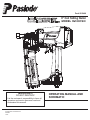 1
1
-
 2
2
-
 3
3
-
 4
4
-
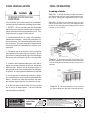 5
5
-
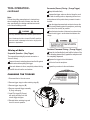 6
6
-
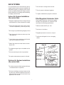 7
7
-
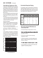 8
8
-
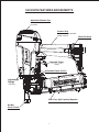 9
9
-
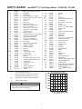 10
10
-
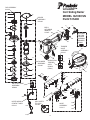 11
11
-
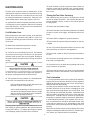 12
12
-
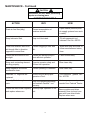 13
13
-
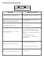 14
14
-
 15
15
-
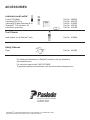 16
16
-
 17
17
-
 18
18
-
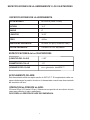 19
19
-
 20
20
-
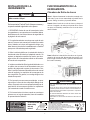 21
21
-
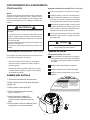 22
22
-
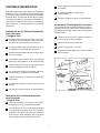 23
23
-
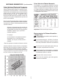 24
24
-
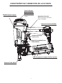 25
25
-
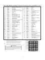 26
26
-
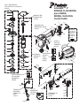 27
27
-
 28
28
-
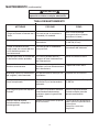 29
29
-
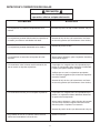 30
30
-
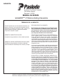 31
31
-
 32
32


Paslode tG100CSN Manual de usuario
- Categoría
- Herramientas eléctricas
- Tipo
- Manual de usuario
en otros idiomas
- English: Paslode tG100CSN User manual

