
Walk-In Installation Manual
Norlake® Kold Locker™, Fast-Trak®, Fineline™,
Enviro-Line & Mini Rooms
Master-Bilt® QS Series, Quick Ship, Bilt2Spec™
& Ready-Bilt™

2
2/23 Rev. S 132617 ©2023 Refrigerated Solutions Group. All rights reserved.
Table of Contents
Introduction 3
Product Safety Policy 4
Tools Required 5
General Information 6-10
Unpacking / Inspection 6
Foam Panel Storage 8
Construction Diagram 9
Section Latches 10
Walk-in Installation 11-34
Floor Installation 12
Site Selection, Base Preparation 14
Wall and Ceiling Panel Construction 22
Panel Installation Order 25
Door / Door Section 26
Exterior Ramp 30
Interior Ramp 31
Membrane Roof 32
Electrical Connections 33
Wiring 33
Walk-in Maintenance 38-48
Door Parts 38
Electrical Connection 47
Final Checklist for Installation 49-50

3
2/23 Rev. S 132617 ©2023 Refrigerated Solutions Group. All rights reserved.
Introduction
Your Refrigerated Solutions Group (RSG) Walk-In Cooler or Freezer was quality engineered and produced
under rigid factory controls. It features the very latest in manufacturing technology plus innovative design
techniques that will provide the ultimate in user convenience.
Please maintain this service-reference material in a handy file for an immediate answer to any questions
you may have concerning your RSG Walk-In. This manual was designed not only to provide guidance
during the installation phase, but to serve its owner as a reference source for years to come. It contains
information pertaining to the operation of its various components, electrical wiring details, maintenance
procedures and adjustment techniques or replacement methods for certain parts.
Please take time to read all sections of this manual. You will be rewarded with a better understanding
of your equipment and will gain product knowledge that will assist you in obtaining the performance that
you should expect from your RSG Walk-In.
Sincerely,
Refrigerated Solutions Group
ANY CORRESPONDENCE PERTAINING TO THIS EQUIPMENT MUST CONTAIN THE MODEL
NUMBER AND THE SERIAL NUMBER AS THEY APPEAR ON THE DATA PLATE LOCATED ON THE
INSIDE OF THE DOOR SECTION.
Refrigerated Solutions Group
891 County Road U
Hudson, WI 54016
800-955-5253 Norlake Foodservice Sales
800-477-5253 Norlake Scientific Sales
800-388-5253 Norlake Parts/Service
800-647-1284 Master-Bilt Sales
800-684-8988 Master-Bilt Parts/Service

4
2/23 Rev. S 132617 ©2023 Refrigerated Solutions Group. All rights reserved.
PRODUCT SAFETY POLICY
We strive to provide those who buy product with equipment which is:
1.
Developed by applying professional engineering principles in product research, development and user safety.
2.
Designed to comply with or exceed industry performance and safety regulations.
3.
Thoroughly reviewed and professionally tested for function, reliability and product safety.
4.
Manufactured according to our professional purchasing, production and quality control standards designed to
assure continued product reliability and safety.
5.
Represented in our advertising and/or product literature in an informational and factual manner created to aid
our customer in their product selection.
6.
Accompanied by clear, complete installation, operation and maintenance instructions designed to assure many
years of satisfactory product performance.
7.
It is only through you, our satisfied customer, that we can continue our past successes in the design,
development and manufacture of refrigeration equipment.
8.
RSG reserves the right to improve upon our products without notice and without imposing on ourselves,
any obligation to make such changes on products previously manufactured.
Warning: Walk-in floor must be kept free of any items that could cause a slip hazard. Spilled liquids, food particles
or any moisture on the walk-in floor can cause the floor to become slippery. Keep the floor surface clean and
dry at all times.
•
Inspect non-skid floor strips on ramps and floor surfaces and replace if worn.
•
Inspect refrigeration system, door gaskets and hardware for proper operation to prevent moisture on walk-
in floor, ceiling or walls.
•
Avoid leaving entry doors open for more than five minutes, which can cause a film of ice or moisture to form
on floor, ceiling and wall surfaces due to the excessive condensation of warm moist air entering the walk-
in. Vinyl strip curtains can be used to reduce the amount of warm moist air entering the walk-in.

5
2/23 Rev. S 132617 ©2023 Refrigerated Solutions Group. All rights reserved.
TOOLS REQUIRED FOR UNCRATING AND INSTALLATION OF YOUR RSG WALK-IN
• LEVEL
• CAULK GUN
• TAPE MEASURE
• SAFETY GLASSES
• HAMMER
• METAL SNIPS
• PRY BAR
• PHILLIPS SCREWDRIVER
• ALLEN WRENCH
• UTILITY KNIFE
• SQUARE
• DRILL DRIVER

6
2/23 Rev. S 132617 ©2023 Refrigerated Solutions Group. All rights reserved.
GENERAL INFORMATION
WALK-IN INSTALLATION GENERAL INFORMATION
This walk-in cooler or freezer was produced utilizing the latest in
manufacturing technology, the highest quality materials available, along
with innovations that make it a distinctive product in its field. Despite rigid
controls in the production of the product, there is no substitute for
thoroughly reading and UNDERSTANDING the instructions that follow.
The result will be an orderly and efficient installation. Take the time to
follow the steps explicitly! NOTE: The most important step is to start
with a level surface.
NOTE: Indoor walk-in(s) must be in an environmentally controlled space.
Relative humidity should be kept between 30% - 60%, maintaining a dew
point of 50°F or less.
UNPACKING / INSPECTION
Delivery Receipt
Check the Delivery Receipt for the number of pieces that made up the shipment and make sure that the number of
pallets, boxes or crates agrees with that number. Each piece should be clearly marked with the same order number
that appears on the Delivery Receipt as the shipper's number. Each individual walk-in is color coded.
Examine the general condition of the shipment and, as soon as unpacking is completed, carefully inspect all parts
for possible shipping damage. If damaged parts are discovered, contact RSG immediately.
Standard Walk-in panels Refrigeration System with
Control Panel

7
2/23 Rev. S 132617 ©2023 Refrigerated Solutions Group. All rights reserved.
GENERAL INFORMATION
Remove protective packaging and locate the
hardware bag.
The hardware bag contains accessory parts for this walk-in together with
a construction diagram, a layout of the walk- in chamber including a
screed assembly for floorless walk-ins, and a detailed packing list of all
parts furnished for this individual walk-in. All parts should be compared to
the packing list.
If discrepancies are found, contact RSG immediately. Some walk-ins
come with an additional orange hardware box.
Locate packing list and use as a reference during uncrating.

8
2/23 Rev. S 132617 ©2023 Refrigerated Solutions Group. All rights reserved.
GENERAL INFORMATION
FOAM PANEL STORAGE
If foam walk-in panels require storage at the job site prior to installation, the following steps must be taken to protect
the panels against both staining from moisture and sunlight and denting by workers and traffic.
Whenever possible, the panels should be stored indoors, and should remain in the crating pallet they were originally
shipped in. If the panels were uncrated as they were unloaded from the delivery truck, and they are being stored
indoors, they should be stored vertically on skids with spacers between the panels.
When storing panels in a vertical position, always place the female rail (grooved) edge down (see illustration below.)
This method of storing panels will provide proper ventilation, permit drain-off of condensation moisture and protect
panels against the formation of white rust stains.
If the panels must be stored outdoors, follow the same procedure as indicated for indoor storage WITH THIS
ADDITION: Cover the panels completely with an opaque polyethylene water-proof material to protect against rain,
snow, heat and sunlight.
The illustration below shows the method for storage outdoors when panels are not left in palletized crates.
Note: RSG always recommends equipment to be installed once received but understands storage may be required.
RSG does not guarantee issues related to storage, such as handling damage, storage damage, panel aging, etc.
We would recommend the locks be oiled and the panels be wiped down with a white oil.

9
2/23 Rev. S 132617 ©2023 Refrigerated Solutions Group. All rights reserved.
GENERAL INFORMATION
CONSTRUCTION DIAGRAM
The construction diagram, as furnished with
each walk- in, is a detailed plan that illustrates
the placement of every wall, corner, ceiling and
floor panel that comprises a complete, individual
walk-in.
The construction diagram for all installations clearly
shows the direction of the male and female formed
profile of every wall panel and every corner panel.
All sections used to construct your walk-in are
marked with a specific part number on the
section, corresponding with its location on
the construction diagram.
If the walk-in is floorless, then a diagram showing
the vinyl screed (floor sealer) arrangement is
provided.
The vinyl screed combines the capability of
retaining the wall panels in place while
providing the inner and outer cove at the junction
of the walls and the building floor (a
requirement of Standard No. 7 of the National
Sanitation Foundation (NSF).
IMPORTANT! Do not attempt to erect a floorless
walk-in FREEZER on an existing building floor that
has not been specially prepared and adequately
insulated for below freezing storage temperatures!
Construction Diagram
RSG Inspection Label and Panel
Specific Part Number

10
2/23 Rev. S 132617 ©2023 Refrigerated Solutions Group. All rights reserved.
GENERAL INFORMATION
SECTION LATCHES
All wall, corner, ceiling and floor panels are joined and locked together by the
mechanical action of section latches which are integrally foamed into the panels
near the perimeter edges. A section latch consists of two halves – a lock housing
which contains a cam actuated locking arm, or hook, and a strike housing which
contains the engagement pin. Both housing halves are securely anchored in the
foam core of the panel. The lock housing is always located in the male-formed edge
and the strike housing will be found in the female-formed edge of the panel.
TO OPERATE LATCHES Fully Extended Cam Lock
Hex wrench provided in
hardware bag
1.
Insert the hex wrench
(packed in the hardware
bag) through the access
hole in the interior
panel metal into the hex
opening of the section
latch. Turn wrench in
a counterclockwise
direction to ensure
that the lock is fully
unlatched
2.
Push the sections
tightly together and turn
the wrench 1/4 turn in a
clockwise direction. This
will engage the locking
arm (hook) over the pin in
the strike housing.
3.
Continue turning the
wrench to a full stop
(approximately 3/4 of a
complete turn from the
unlatched position) to
complete the locking
operation.
Latches on some panels
will have to be turned
counterclockwise to
activate the locking cam.
These latches will be
designated by a "TURN"
sticker.

11
2/23 Rev. S 132617 ©2023 Refrigerated Solutions Group. All rights reserved.
WALK-IN INSTALLATION
SITE SELECTION, BASE PREPARATION AND LEVELING THE FLOOR
WALK-IN COOLER OR FREEZER WITH A FLOOR
One of the most important considerations in the construction of a walk-in cooler or freezer is the building floor or the
surface upon which the walk-in will rest. As with any structure, a firm and level foundation is essential to achieve a
perfect result. If the surface is not perfectly level and smooth, appropriate steps must be taken to provide the proper
base. The positive action of self-closing doors, proper door gasket seal and condensate removal all depend directly
upon the level and plumb installation of all panels.
If the walk-in is to be
installed next to an
existing building
wall(s), make sure
that a MINIMUM OF 2"
REMAINS BETWEEN
THE WALK-IN AND
THE BUILDING
WALL(S) to allow for
irregularities of the
building wall(s) and to
permit a free flow of
air between the two surfaces.
NOTE: Indoor walk-in(s) must be in an environmentally controlled
space. Relative humidity should be kept between 30% - 60%,
maintaining a dew point of 50°F or less.
In some cases, the surface upon which the walk-in is to be
installed was especially prepared for installation and it is perfectly
level and smooth. The walk-in floor, in this case, may be installed
without further preparation. Before beginning, however, an
appropriate vapor barrier must be placed over the surface that the
walk-in will occupy. Asphalt felt paper (50#) or a 6-mil polyethylene
film, are suggested materials. These are provided by the
installing contractor. A vapor barrier is required on both
indoor and outdoor applications.

12
2/23 Rev. S 132617 ©2023 Refrigerated Solutions Group. All rights reserved.
WALK-IN INSTALLATION
FLOOR INSTALLATION (Shim Leveling Method)
FOR WALK-INS SUBJECT TO LIGHT TO MODERATE LOADS
Locate the highest point within the perimeter lines. A transit or
surveyor’s level or rotary laser level is an ideal instrument to use for
locating this point. When the highest point is located, mark it directly
on the floor and refer to the construction diagram to determine where
the high point is located with respect to the walk-in floor plan.
One of the most important procedures that will be encountered in the
construction of a walk-in with a floor is LEVELING THE FLOOR. It
must be PERFECTLY LEVEL! If it is not, the wall panel will follow the
irregularities of the walk-in floor which will directly affect subsequent
procedures such as latching, panel gasket seal, ceiling panel
assembly among others.
Using the construction diagram as a guide, select the floor panel that will be located directly over the highest point
and place it in that position while observing the drawn outline on the building floor.
After the first floor
panel is positioned, it
must be properly
leveled. To achieve
this, shimming
material of varying
thicknesses must be
used. Cedar building
shingles are ideally
suited for this
procedure.
HOWEVER, OTHER
MATERIALS THAT
ARE RESISTANT TO
ROTTING OR
COMPRESSION ARE
ALSO ACCEPTABLE.
IMPORTANT! EVERY
FLOOR PANEL MUST
BE SUPPORTED ON
ALL FOUR SIDES
AND THE ENTIRE
UNDERSIDE, AT LEAST EVERY 12" BY EITHER THE BUILDING FLOOR OR BY SHIMMING.
After the first floor panel has been leveled perfectly, trim away the excess shim material so that none projects from
the panel at any of the four edges.
From the construction diagram, determine which floor panel will be installed next and where it will be situated on
the floor plan. Prepare shimming material for the second panel at each point where shimming material was used
beneath the first floor panel. The shimming material thickness must be such that it will support the second floor
panel at the same height as the first panel along the entire length of the joint. NOTE: In many cases, the shimming
material will be the same thickness as the adjacent shimming under the first panel.

13
2/23 Rev. S 132617 ©2023 Refrigerated Solutions Group. All rights reserved.
WALK-IN INSTALLATION
Place the second panel in position next to the first floor panel but
DO NOT LOCK!
Shim the second panel, where necessary, using the same procedure
as was used on the first panel. When all four edges of the second
floor panel are properly shimmed, lock the two panels securely
together. Using the same technique for leveling, check the levelness
of the two sections in all directions by placing the level across the
joint at several points and, again, check the levelness of the floor
panels in the direction of the panel joint.
Refer to the construction diagram and install the remainder of the
floor panels using the same procedure as was used for the first and
second floor panels. When all the floor panels are installed and
leveled perfectly, check the section latches for full and complete
locking.
Trim excess vapor barrier.

14
2/23 Rev. S 132617 ©2023 Refrigerated Solutions Group. All rights reserved.
WALK-IN INSTALLATION
SITE SELECTION, BASE PREPARATION
WALK-IN COOLER WITHOUT A FLOOR INSTALLED ON 1” VINYL SCREED
IMPORTANT! Do not attempt to construct a floorless walk-in FREEZER on an existing building floor that has not
been specially prepared and adequately insulated for below freezing storage temperatures. Note: All thermal
breaks in floor slab must be exposed, including the partition wall.
To install a vinyl screed assembly on an existing floor, proceed as follows:
Locate the screed (floor sealer) diagram, which was packed in the hardware box and, using it as a guide, draw an
outline of the outside dimensions of the installed screed directly onto the building floor where the walk-in will be
situated. These dimensions will be 1 1/2” larger than the overall dimensions of the walk-in in both directions.
If the walk-in is to be installed next to an existing building wall(s), make sure that a MINIMUM OF 2” REMAINS
BETWEEN THE DRAWN OUTLINE AND THE BUILDING WALL(S) to allow for irregularities of the building wall
(s) and to permit a free flow of air between the two surfaces. CAREFULLY CHECK FOR SQUARENESS by confirming
that the two dimensions between opposite corners are equal (Figure 1).
One of the most important procedures that will be encountered in the base preparation is LEVELING THE SCREED.
It must be PERFECTLY LEVEL! If it is not, the wall panels will follow the irregularities of the building floor which will
directly affect subsequent procedures such as panel latching, panel gasket seal, ceiling panel assembly and others.
After the outline of the screed assembly is completed, locate the highest point within the outline on the floor where
the screed will be installed. Screed sections are 5 1/2” wide. A transit or surveyor’s level is an ideal instrument for
this purpose. Mark the highest point on the floor (Figure 2) and, referring to the screed diagram, identify and locate
the appropriate screed section and position it directly over the highest point.
Figure 1

15
2/23 Rev. S 132617 ©2023 Refrigerated Solutions Group. All rights reserved.
5
WALK-IN INSTALLATION
After the first screed section is positioned, it must be LEVELED PERFECTLY not only over its length but, across
its width, as well. To achieve this, shimming material will most likely be required. Vinyl floor tile is ideally suited for
this purpose. However, other materials that are resistant to rotting or compression are acceptable. IMPORTANT!
EVERY SECTION OF SCREED MUST BE SUPPORTED AT LEAST EVERY 12’’ BY EITHER THE BUILDING
FLOOR OR BY SHIMMING (Figure 3).
Assuming that the first screed section has been perfectly leveled, refer to the screed diagram and select an
adjoining screed section and level it perfectly in both directions, shimming wherever necessary. Continue leveling
the remainder of the screed sections until the entire assembly is in position. Check the assembly to make sure that
the outer edges are located exactly on the drawn outline on the building floor.

16
2/23 Rev. S 132617 ©2023 Refrigerated Solutions Group. All rights reserved.
WALK-IN INSTALLATION
When the entire screed assembly is leveled and supported by shimming, as required, CAREFULLY AND
WITHOUT DISTURBING THE SHIMMING MATERIAL, lift the screed sections, tip them upside-down and apply a
heavy bead of construction sealant to the bottom of the screed section along both of the edges that contact the
building floor surface. The diameter of the sealant bead should be larger than the thickest shimming material to
ensure a complete, air-tight seal along the entire length of the screed (Figure 4). NSF approved sealant is provided
and will be found in the hardware box.
Immediately after applying the construction sealant to a screed section, replace the screed section to its original
location on the building floor WITHOUT DISTURBING THE SHIMMING MATERIAL and place a sealer splice every
joint in the screed assembly (Figure 4). Since the sealer splice is intended to keep adjacent screed sections in
alignment, approximately one-half of the sealer splice should lap each section. It need not be fastened in place
(Figure 4). NOTE: Seal all screed joints with sealant. Make a final check for squareness, levelness and whether
the screed assembly is located properly with respect to the drawn outline on the building floor.
Follow by securing the screed assembly to the building floor with fasteners that are appropriate for the building
floor. These fasteners are not provided and must be obtained by others.
Fasteners should be applied down the center line of the inside of the screed at intervals of approximately 36’’;
however, where shimming is used, apply the fasteners through the shimming material, NOT BETWEEN the
shimming. When the entire assembly is secured in position, trim away all excess construction sealant and shimming
on both edges of the screed. Trim sealant flush with the edge of the screed and touch up any areas where the
construction sealant is not making a perfect seal (Figure 4).
NOTE: If the building floor was specially prepared for the installation and no low or high points are detectable, it is
possible that no shimming will be necessary. It will then only be necessary to apply construction sealant to the
bottom of the screed and secure the screed directly to the building floor. The entire procedure, as described, must
be followed explicitly, however, except for the details that pertain to the shimming.

17
2/23 Rev. S 132617 ©2023 Refrigerated Solutions Group. All rights reserved.
WALK-IN INSTALLATION
ALTERNATE SHIMMING METHOD FOR 1’’ VINYL SCREED
If the surface that the vinyl screed will occupy is level, except for an occasional low point, the screed may be
secured directly to the building floor and compensation for the low points may be achieved by shimming the support
shoulders on the inside of the screed.
When employing this method, the low points should be marked on the building floor in the vicinity of the drawn
outline for reference. After the screed has been sealed and secured, leveling may proceed with special attention
being focused in the areas marked as being low points.
Vinyl floor tile is often chosen as shimming material and strips (5/8’’ wide maximum) are cut and placed on top the
supporting shoulders of the screed to provide a level surface for the wall sections to rest upon. Strips of tape should
be applied to hold the shimming material in place (Figure 5).
IMPORTANT! Shimming the support shoulders on the inside of the screed is ideally suited for minor irregularities
on the building floor and has the advantage of complete screed-to-floor contact over the entire perimeter of the
assembly. IT IS NOT RECOMMENDED, HOWEVER, FOR EXTREMELY IRREGULAR BUILDING FLOORS.
Excessively thick shimming material on the support shoulders may elevate the wall panels to a point where the
effectiveness of the uppermost screed sealing flanges would be compromised. Shimming thickness of more than
3/4’’ should be avoided! If shimming the support shoulders of the screed is selected, the entire procedure, as
described, must be followed explicitly to ensure squareness and levelness over the entire screed assembly.

18
2/23 Rev. S 132617 ©2023 Refrigerated Solutions Group. All rights reserved.
WALK-IN INSTALLATION
SITE SELECTION, BASE PREPARATION
WALK-IN COOLER OR FREEZER WITHOUT A FLOOR INSTALLED ON FOAMED SEALERS
IMPORTANT! Do not attempt to erect a floorless walk-in FREEZER on an existing building floor that has not been
specially prepared and adequately insulated for below freezing storage temperatures. Note: All thermal breaks
in floor slab must be exposed, including the partition wall. To install a foamed sealer (screed) assembly on an
existing floor, or on a properly prepared floor for freezers, proceed as follows:
Locate the floor sealer (screed) diagram that was packed in the hardware box and, using it as a guide, draw a properly
dimensioned outline of the sealer (screed) assembly directly onto the building floor precisely where the walk-in will
be situated. These lines will be the same dimensions as the dimensions of the walk-in in both directions. If the walk-
in is to be installed next to an existing building wall(s), make sure that a MINIMUM OF 2” REMAINS BETWEEN
THE DRAWN OUTLINE AND THE BUILDING WALL(S). This space will allow for irregularities in the building wall(s)
and will permit a free flow of air between the two surfaces. CAREFULLY CHECK FOR SQUARENESS by confirming
that the dimensions between opposite corners are equal (Figure 1).
Since the foamed sealer (screed) is retained in position by a 3/8” thick plywood sealer guide, which will be secured
to the building floor, it is imperative that the sealer guide be accurately located, as well, on the building floor. Refer
to the sealer guide diagram which was also packed in the hardware box. On the diagram, you will notice that the
sealer guide is located 7/8” INSIDE the drawn outline which represents the outside dimensions of the sealer (screed)
assembly. Further, Fig. 1 illustrates that the sealer guide is 2 1/4” wide centered beneath a 4” wide sealer leaving a
border of 7/8” along each edge. Draw another outline of the outside dimensions of the sealer guide directly onto
the floor. There should be exactly 7/8” between the new sealer guide outline and the previously drawn sealer (screed)
outline (Figure 2, on next page).
Figure 1

19
2/23 Rev. S 132617 ©2023 Refrigerated Solutions Group. All rights reserved.
2” MINIMUM
WALK-IN INSTALLATION
Figure 2
One of the most important procedures that will be encountered in the base preparation is LEVELING THE SEALER
(SCREED). It must be PERFECTLY LEVEL! If it is not, the wall panels will follow the irregularities of the building
floor which will directly affect subsequent procedures such as panel latching, panel gasket seal, ceiling panel
assembly and other.
After the outline of the sealer (screed) and the sealer guide is completed, as shown in Figure 2, locate the highest
point within the outline on the floor where the screed (sealer) will be installed. (Sealer sections are 4” wide). A
transit or surveyor’s level is an ideal instrument for this purpose. Mark the highest point on the floor as illustrated
on Figure 3.
2” MINIMUM
2” MINIMUM

20
2/23 Rev. S 132617 ©2023 Refrigerated Solutions Group. All rights reserved.
WALK-IN INSTALLATION
SEALER GUIDE INSTALLATION
Locate the SEALER GUIDES. They are bundled together and packed along with the walk-in corner or wall panels
and are labeled accordingly. Sealer guides are strips of 3/8” plywood 2-1/4” wide and 8’ long as shown in Fig. 1.
Refer to the SEALER GUIDE DIAGRAM. Position them according to the diagram and cut the guides to fit.
Each sealer guide, when positioned properly, will have its outer edge precisely over the INSIDE OUTLINE drawn
on the building floor, Figure 2, and its outer edge will be exactly 7/8” from the outline which represents the foamed
sealer outer edge. The quality of workmanship performed in locating and securing the sealer guides will be
transmitted directly to the location of the foamed sealers (screeds) and, subsequently, to the overall construction
of the complete walk-in. BE EXACT! Refer to Figure 1 and Figure 2.
When all sealer guides are in position, make a final CHECK FOR SQUARENESS and secure them to the building
floor with fasteners that are appropriate for the surface. NOTE: This can either be a mechanical fastener or
construction grade adhesive. If the sealer guide is positioned over a polystyrene or polyurethane thermal breaker,
a compatible construction adhesive may be used.
FOAMED SEALER (Screed) INSTALLATION
Refer to the FOAMED SEALER DIAGRAM. Identify and locate the sealer section that will be positioned directly
over the highest point which was determined earlier and marked on the building floor (Figure 3).
NOTE: All foamed sealers are male formed on one end and female formed on the opposite end. The configuration
of the ends is clearly indicated on the diagram. Also, make certain that the strike housing portion of the section
latches is visible on the upper edge of the sealer when it is in position (see Figure 1 and Figure 2).

21
2/23 Rev. S 132617 ©2023 Refrigerated Solutions Group. All rights reserved.
WALK-IN INSTALLATION
Figure 5
After the first sealer (screed) section is positioned over the sealer guide and over the highest point, it must be
LEVELED PERFECTLY not only over its length but, across its width, as well. To achieve this, shimming material
will probably be required. Vinyl floor tile cut in strips 7/8” wide by 6” long make ideal shimming strips that can be
placed beneath the sealer, wherever necessary, to achieve levelness.
IMPORTANT: EVERY SECTION OF SEALER (SCREED) MUST BE SUPPORTED AT LEAST EVERY 24” BY
EITHER THE BUILDING FLOOR OR BY SHIMMING. Avoid using shimming strips less than 6” long whenever
possible (see Figure 4).
Assuming that the first sealer (screed) section has been perfectly leveled, refer to the sealer diagram and select an
adjoining sealer section and level it perfectly in both directions, shimming wherever necessary. NOTE: Sealer
(screed) sections 8” high or more employ section latches for end-to-end locking. CAREFULLY flush the upper edges
and the inner or outer surfaces of adjoining sealer sections while locking them together (Figure 5). Continue leveling
the remainder of the sealer sections until the entire assembly is in position.
When the entire sealer assembly is leveled, apply NSF approved sealant to achieve a vapor seal between the
bottom edge of the sealer and the building floor. This sealant is provided and is packed in the hardware box. The
sealant must be applied to the inner and outer surfaces of the sealer (screed) assembly. Make certain that the
sealant produces a complete, air-tight seal, without gaps, and that special care is taken to seal the shimming
material appropriately.
After the sealant has had an opportunity to set up, trim away all excess material flush with the edges of the sealer
(screed) assembly and touch up any areas where the sealant is not making a perfect seal (Figure 5.).

22
2/23 Rev. S 132617 ©2023 Refrigerated Solutions Group. All rights reserved.
WALK-IN INSTALLATION
WALK-IN INSTALLATION
WALL AND CEILING PANEL CONSTRUCTION
The installation instructions that follow apply to any walk-in cooler or
freezer where the wall panels are supported either by foamed walk-in
floor panels or by a floor sealer (screed) assembly which has been
accurately located and properly leveled. NOTE: The procedure for
constructing wall and ceiling panels will be identical in all cases. NOTE:
The walls do not lock to vinyl sealers but will lock to foam sealers when
used.
To aid in the construction process, the floor plan furnished with your
walk-in has part numbers listed for each wall, corner, ceiling and floor
section. Match the part number on the floor plan to the label on the
interior of each panel to determine the current placement for each panel.
Notice, also, that the section latch access holes on the vertical edge of
the panel are always on the interior of the panel.
Select the first panel to be installed, typically beginning with a CORNER
PANEL. Notice that the panel is labeled "Top" along with a part number
indicating that when the panel is in its proper position, the labeled end will
be up.
Position the corner panel in the proper location on the walk-in floor or vinyl
screed assembly and, IF THE WALK-IN HAS A FLOOR, flush the corner
panel with the corner of the floor panel in both directions and lock it
securely to the floor panel.

23
2/23 Rev. S 132617 ©2023 Refrigerated Solutions Group. All rights reserved.
WALK-IN INSTALLATION
If the first corner panel is supported by a 1" vinyl
sealer (screed), seek assistance to support the
corner panel in a vertical position until succeeding
wall panels are installed. Wall and corner panels
do not lock to the vinyl sealer (screed).
Select the next panel as indicated on the floor
plan and position it on the floor or sealer (screed)
close enough to the first panel installed so that
section latch engagement is possible.
Making sure that the two panels are perfectly aligned at the TOP EDGE and
that the VERTICAL JOINT of the two panels are perfectly flush, turn the
section latches on the vertical edge of the panel until they are completely
engaged.
IMPORTANT! Confirm that the top edges of the adjoining panels are aligned
perfectly.
Correct
If misalignment is encountered, merely lift the lowest panel edge while
locking to achieve alignment and, when all latches are engaged, permit the
locked panels to resume their normal position on the walk-in floor or sealer
(screed).
DO NOT SHORT-CUT! TAKE ENOUGH TIME TO PROPERLY ALIGN ALL
SECTIONS.
Misalignment

24
2/23 Rev. S 132617 ©2023 Refrigerated Solutions Group. All rights reserved.
WALK-IN INSTALLATION
As each wall panel or corner panel is constructed and locked in an
adjoining panel along the vertical joint, engage the section latches to
the floor panels by turning the hex locking wrench ONLY ABOUT 1/4
TURN CLOCKWISE.
Make certain that the wall or corner panel is perfectly aligned with the
floor panel or foamed sealer before engaging the section latches.
Continue constructing panels
according to the part numbers shown
on the floor plan, and follow, explicitly,
the technique described for panel
alignment.
CEILING PANELS will be constructed
at specific intervals to facilitate the
installation. The intermittent ceiling
panel construction is scheduled to
allow the ceiling panels to serve as
supporting ties between opposite
walls as the installation progresses.
CAUTION! DO NOT SLIDE CEILING PANELS
INTO POSITION! To avoid gasket damage,
elevate the ceiling section clear of the wall
section while bringing it into position.
When adjoining ceiling panels are in position,
adjust the exterior edges so that they are
perfectly flush with one another and with the wall
panels directly below them. Lock the ceiling
panels securely to each other. DO NOT LOCK
ceiling panels to wall panels at this time.
NOTE: If local conditions, such as existing
building walls, make it difficult to align ceiling
panels with each other from the exterior, locate
a step ladder near the interior walls to visually
inspect the alignment and adjust as necessary.

25
2/23 Rev. S 132617 ©2023 Refrigerated Solutions Group. All rights reserved.
WALK-IN INSTALLATION
PANEL INSTALLATION ORDER

26
2/23 Rev. S 132617 ©2023 Refrigerated Solutions Group. All rights reserved.
WALK-IN INSTALLATION
DOOR/DOOR SECTION
A standard door/door section consists basically of a single wall panel that
contains an entrance door and several accessories. The electrical
components contained in this panel were prewired at the factory. They
include the anti-condensate door opening heater, the pilot light, and switch
and a vapor proof interior light.
The door was factory installed on the door panel framing fixture, checked for
squareness and for proper operation under controlled conditions.
CAUTION! While installing the door/door section, extreme care must be
taken to avoid twisting the panel or handling the assembly in such a manner
that it is not square when it is installed. The self-closing feature, door closure
operation and a perfect gasket seal all depend a great deal upon a SQUARE
and PLUMB door/door section.
After all the wall and door panels have been constructed and locked securely
together and all the ceiling panels have been positioned above the wall
panels, the ceiling panels have been locked securely to each other, re-check
the position of the ceiling panels with respect to the wall panels.
Now lock all ceiling panels securely to the wall panels.
Recheck the position of the wall panels with respect to the floor panels and
lock them securely together.
NOTE: When a 1" vinyl floor sealer (screed) is used, no attachment to the
wall panels is required.
Completed
Walk-in with floor Completed Walk-in floorless- shown
with vinyl floor sealer

27
2/23 Rev. S 132617 ©2023 Refrigerated Solutions Group. All rights reserved.
WALK-IN INSTALLATION
NOTE: If, for some reason, conditions on the site prohibit the
installation of the walls and ceilings in the recommended order,
install the wall and ceiling panels in a logical sequence that will
permit accessibility for installation of the last panel. Remember
to schedule ceiling panel installation at the proper intervals to
serve as supporting ties between installed wall panels.
Locate the plug buttons which were packed in the hardware bag
and, after checking to make sure that the hex wrench comes to
a full stop on each section latch, insert a plug button into every
latch access hole.
SLAM BRACES
The door/door section frame on most floorless walk-ins will be
fitted with slam braces, one on each of the interior, vertical frame
members. These braces will require attachment to the building
floor.
Their purpose is to positively locate the lower extremities of the
door frames and prevent any movement that might occur at the
point where the door frame rests on the floor sealer (screed).
When 1" vinyl floor sealers are furnished, they will be notched to
accommodate the slam brace location.
The slotted holes in the vertical leg of the slam brace permit adjustment in either direction to allow the slam brace
to contact the building floor properly. Fasteners suitable for securing the slam braces to a concrete building floor
are packed in a bag and attached to one of the slam braces. For other types of building floors, the appropriate
fastener must be provided by others.
IMPORTANT! Make sure that the door/door section is PERFECTLY PLUMB before attaching the braces to the
building floor. The holes in the slam brace for attachment to the building floor are intentionally round so that no
shifting can occur after they are secured. Make sure the slam braces have been secured to the building floor.
The recommended hole
size for PARABOLT
ANCHOR is 3/8” X 2-1/4”
Install anchor Attach slam brace with
fastener provided

28
2/23 Rev. S 132617 ©2023 Refrigerated Solutions Group. All rights reserved.
WALK-IN INSTALLATION
Figure 11
Figure 12
THRESHOLD ATTACHMENT
The threshold was attached at the factory to the lower portion of the door section and it is positioned in such
a manner that no adjustment is required. It must, however, be attached to the building floor to complete the
installation.
IMPORTANT! Make sure that the slam braces are securely fastened to the door section and to the building
floor before attaching the threshold to the building floor. Both edges of the threshold should be attached with
fasteners that are appropriate for the building floor and, since the floor surfaces vary so greatly in composition,
no fasteners are provided and should be obtained by others (Figure 12).
Apply sealant under threshold
Note: Add sealant between
threshold and floor to seal.
IMPORTANT!
MAKE SURE THAT THE DOOR/DOOR
SECTION IS PERFECTLY PLUMB
BEFORE ATTACHING THE SLAM
BRACES TO THE FLOOR.

29
2/23 Rev. S 132617 ©2023 Refrigerated Solutions Group. All rights reserved.
WALK-IN INSTALLATION
Figure 13
SEALING THE JUNCTURE OF WALLS TO BUILDING FLOOR
Apply a generous amount of NSF approved sealant to achieve a vapor seal between the bottom edge of all wall,
corner, door and partition panels and the building floor. The sealant must be applied to both inner and outer edges
of all perimeter walls and to both edges of partition walls where they meet the building floor. Make certain that the
sealant produces a continuous, air-tight seal, without gaps, and that special care is taken to seal around the
shimming material.
After the sealant has had an opportunity to set up, trim away all excess sealant flush with the edges of the walls.
Touch up any areas where the sealant is not making a perfect seal (Figure 8).
COVE MOLDING
To comply with the requirements of Standard No. 7, National Sanitation Foundation, a cove molding with a minimum
radius of 1/4” must be applied to cover the juncture of the walk-in walls and the building floor. For with floor models
cove molding is required on exterior walls only.
Cove molding and adhesive for application are not normally provided. They are readily available at most building
materials suppliers.
Before applying cove molding, make final inspection of the area that will be covered with the molding to make sure
that the sealant is intact and making perfect vapor seal. If not, add sealant as required. Read and follow the
instructions prepared by the manufacturer of the cove molding and the adhesive before proceeding with the
installation (Figure 13).
If tile and grout are employed as floor material and, if base title is intended to produce the cove required, make sure
that the inside radius of the base tile is at least 1/4”.

30
2/23 Rev. S 132617 ©2023 Refrigerated Solutions Group. All rights reserved.
WALK-IN INSTALLATION
EXTERIOR RAMP INSTALLATION INSTRUCTIONS
Center ramp in front of door opening. Then using the 1-1/2” x 1-1/2” x 3-1/2” angle and screws provided, attach the
ramp to the walk-in, as in the illustration below.
If the exterior ramp is located outdoors, an appropriate vapor barrier must be placed over the surface that the
walk-in will occupy. Asphalt felt paper (50#) or a 6-mil polyethylene film, are suggested materials. These are
provided by the installation contractor.

31
2/23 Rev. S 132617 ©2023 Refrigerated Solutions Group. All rights reserved.
WALK-IN INSTALLATION
INTERIOR RAMP INSTALLATION INSTRUCTIONS
Step 1
After floor sections are in place and fully
locked together, apply approximately 1/8”
bead of sealant to the interior metal, 3/8” in
from the ramp cut out. Also apply
approximately 1/8” bead of sealant to the
center of the exterior metal lip.
Step 2
Place ramp into position by lining up the pre- drilled
holes in the ramp with those pre-drilled in the interior
floor then secure the ramp into the floor with the #8 x
1/2” screws provided.
Step 3
Install the non-skid floor fabric. 6” x 24” non-
skid tape strips are applied to cover the ramp
and back seam of the ramp to
the floor panels. 3” x 24” non-skid tape strips
are applied to cover the side seams of the
ramp to the floor panels.
Apply sealant where the door section meets
the interior and exterior of the floor panel and
ramp. Also, apply sealant under the door
threshold.

32
2/23 Rev. S 132617 ©2023 Refrigerated Solutions Group. All rights reserved.
WALK-IN INSTALLATION
MEMBRANE ROOF INSTALLATION INSTRUCTIONS
IMPORTANT NOTE:
IF THIS WALK- IN INCLUDES CEILING MOUNT CAPSULE-PAK™ REFRIGERATION SYSTEMS, PLEASE
REFER TO CAPSULE-PAK™ REFRIGERATION INSTALLATION MANUAL. ALSO, BE SURE THE INTERIOR
COIL IS HUNG CORRECTLY PER THE REFRIGERATION MANUAL INSTRUCTIONS BEFORE INSTALLING
THE MEMBRANE.
To help prevent future leaks from membrane punctures, cuts, or tears, apply a bead of silicone to all
ceiling seams and ceiling-to-wall horizontal seams.
Step #1
After walk-in is completely assembled, lay E.P.D.M. over ceiling topside and trim to a 6" overlap on all four sides.
Step #2
Fold all four corners as shown below.
Step #3
Attach trim, refrigeration hood and door hood with sheet metal screws provided. On some models the trim
may have to be cut to fit.

33
2/23 Rev. S 132617 ©2023 Refrigerated Solutions Group. All rights reserved.
WALK-IN INSTALLATION
Step #4
Trim off all excess rubber membrane from under aluminum trim and hoods with utility knife. Be careful not to
scratch the surface of the panels with the knife.
ELECTRICAL CONNECTIONS
For walk-in cooler or freezer with a single interior light mounted on the door section.
CAUTION: ELECTRICAL CONNECTIONS TO THE WALK-IN MUST COMPLY WITH APPLICABLE
PORTIONS OF THE NATIONAL ELECTRICAL CODE AND ANY OTHER ELECTRICAL CODES THAT
MAY HAVE JURISDICTION OVER THE INSTALLATION!
A dedicated electrical power supply circuit for the walk-in is recommended.
WARNING! DISCONNECT THE SELECTED POWER SUPPLY CIRCUIT AND ATTACH A TAG TO THE
DISCONNECT SWITCH INDICATING THAT THE CIRCUIT MUST NOT BE ENERGIZED WHILE
SOMEONE IS WORKING ON THE LINE.
WIRING
The cooler or freezer door panel contains several electrical
components that were prewired at the factory. They include
the anticondensation door opening heater, the pilot
light/switch and LED interior light mounted on the door panel.
NOTE: It is the electrical contractor's responsibility to
provide the necessary wiring, connections, conduit and
fittings to complete the hook-up.
The junction box adjacent to the light fixture contains the electrical leads that are prewired to the electrical
components in the door section. Make your electrical connections here.
Affixed to the interior of the door section is a label which describes the electrical characteristics and the
energy consumption described in watts and amperes.

34
2/23 Rev. S 132617 ©2023 Refrigerated Solutions Group. All rights reserved.
WALK-IN INSTALLATION
IMPORTANT! When all field wired connections are completed in the junction box located on top of the ceiling
section, be sure to THOROUGHLY SEAL the conduit fitting through which the wiring projects into the junction box.
The silicone sealant provided is well suited for this purpose. Failure to do so will permit moisture to form within the
junction box and electrical fixture(s) and potentially cause a short.
POSITIONING THE THERMOMETER SENSING BULB
For convenient monitoring of the temperature of the storage compartment of this walk-in, a remote reading
thermometer has been installed in the door section at about eye level. It is a flush panel mount with an LED readout.
For optimum accuracy, the sensing bulb must be exposed to the air that is being
monitored. Make certain that the sensing bulb is not positioned near the interior light
or any other heat producing device, nor should it be located where stored products
shield the sensing bulb from the circulating air
pattern within the walk-in. The long sensing lead is more than adequate to provide an
ideal sensing bulb placement on the inside surface of the door section or an adjacent
wall or corner panel. When the location is finalized, an adhesive backed, plastic clip is
used to secure the sensing bulb to that surface.
To prevent possible damage to the door opening heater and/or to the protective globe
over the interior light, DO NOT energize the door/door section until the interior
temperature has been reduced to the normal operating range by refrigeration. A
caution label is affixed to the door section near the vapor proof light to serve as a
reminder.
PRESSURE RELIEF PORT
If a pressure relief port is supplied, connect it to a 115/60/1 VAC power supply.
WIRING DIAGRAM: A wiring diagram showing the electrical components contained in
the door/door section circuitry involved as shown. Always refer to the wiring diagram if
it becomes necessary to replace any of the components.

35
2/23 Rev. S 132617 ©2023 Refrigerated Solutions Group. All rights reserved.
WALK-IN INSTALLATION

36
2/23 Rev. S 132617 ©2023 Refrigerated Solutions Group. All rights reserved.
WALK-IN INSTALLATION
WALK-IN DOOR WITH NL508 LIGHT SWITCH WIRING DIAGRAM

37
2/23 Rev. S 132617 ©2023 Refrigerated Solutions Group. All rights reserved.
WALK-IN INSTALLATION
WALK-IN DOOR WITH NL708 OR MBWA-1 LIGHT SWITCH WIRING DIAGRAM

38
2/23 Rev. S 132617 ©2023 Refrigerated Solutions Group. All rights reserved.
WALK-IN MAINTENANCE
ADJUSTING DOOR HINGE ON NORLAKE WALK-INS
RSG 26”, 30”, & 36” wide walk-in doors are provided with an adjustable hinge. The adjustable hinge provides the
ability to square a door within the door jamb.
If a door requires adjustment:
Open the door and you will find a small chrome plug button, on the edge of the door behind the upper hinge. Before
any adjustment you must first slightly loosen the screws on the hinge strap on the door. Then pop off the chrome
plug button. Now you can access the adjustment screw. You should only make minor adjustments and then close
the door to view if the adjustment rectified the situation. When complete replace the chrome plug and re-tighten the
screws on the hinge strap.
NOTE: On doors with a kick plate you may have a center (3rd) hinge. In this case there is a 2nd adjustable hinge.
You will need to loosen the screws on both the top and center hinge(s) and make minor adjustments in both areas.
ADJUSTING DOOR HINGE ON MASTER-BILT WALK-INS
• Place shims under door (see figure 1 below).
• If adjusting the door, loosen but do not remove the screws that attach the hinge blade to the door (see
figure 2 below for location of screws).
• If replacing hinges, remove the hinge blade screws.
• Shim under door as necessary to provide a 1/4" space between top of door and the door frame to ensure
square fit (see figure 1).
• Tighten or reinstall screws attaching the hinge blade to the door.
• After adjusting or replacing the hinges, remove shims and check the space at the top of the door periodically
for proper alignment.
Figure 1
Figure 2

39
2/23 Rev. S 132617 ©2023 Refrigerated Solutions Group. All rights reserved.
WALK-IN MAINTENANCE
REPLACEMENT OF THE MAGNETIC DOOR GASKET ASSEMBLY
For your convenience and safety, it is advisable to remove the entire door assembly
from the walk-in cooler or freezer before attempting to replace the door gasket.
Prepare a smooth, clean surface on which the exterior surface
of the door assembly can be placed without marring or scratching the finish.
DOOR ASSEMBLY REMOVAL - ALL FOAMED WALK-IN COOLER OR
FREEZERS WITH CAM LIFT HINGES
NOTE: For doors equipped with a spring hinge, see the door removal instructions label on the interior of the door
near the top hinge. When removing the door assembly from any walk-in, solicit the aid of an assistant during the
door removal and replacement procedures.
1.
Open door to dwell position, stopping at approximately 120°.
2.
Put mark on floor to indicate position of door, see sketch.
3.
Lift door off frame.
4.
To replace door, line up door with mark on floor.
5.
Place hex hole in hinge straps over hex rods and lower door.
RESETTING SPRING HINGES
For the top spring-loaded hinge, you will need to reset the spring/hexagon pin. With the door installed, closed and
locked, remove the screws from the spring-loaded hinge strap on the door only. You will need to hold the hinge strap
against the door to prevent the strap from springing out towards you after the screws are removed. Remove the
strap portion from the door by pulling upward. Hold the strap portion above the remainder of the hinge so that the
strap is flat against the door. Bring the strap portion back down towards the door so that it meets the hexagon pin.
You have now reset the spring. Insert the screws back into the strap and door. Note: Under normal conditions, the
spring has no tension when the door is closed.

40
2/23 Rev. S 132617 ©2023 Refrigerated Solutions Group. All rights reserved.
WALK-IN MAINTENANCE
DOOR GASKET REPLACEMENT
1.
Place the door, exterior face down, gasket up, on a clean, smooth surface
that will not mar or scratch the finish.
2.
The magnetic door gasket consists of a cavity containing the magnetic strip,
a bellows cavity that permits the gasket to conform to irregular surfaces, and
a base section that features a dart- shaped projection that serves as the
attachment means when it is forced into the slot in the door breaker.
3.
To remove the original magnetic gasket assembly, grasp the gasket at one
of the corners and pull the dart-shaped projection out of the retainer slot in
the door breaker. Pull slowly and examine your progress to avoid tearing the
projection which will then remain in the retainer slot.
4.
Remove the entire gasket assembly and examine the retainer slot to make
sure that it is free of gasket material or other debris.
5.
Starting at one corner, insert the dart-shaped projection of the replacement
gasket into the retainer slot and, using a rubber mallet, drive the dart into the
retainer slot. HINT: Cover the face of the rubber mallet with masking tape to
prevent smudging the gasket. Attach only about wo inches (2") of the gasket
in each direction away from the corner.
6.
Use the same procedure as in Step 4 at the remaining corners and midway
between the corners on the long sides of the door.
7.
Using the rubber mallet, drive the dart into the retainer slot working from
the center of each side toward the corners.
8.
Lift the gasket base on the outer edge of the gasket and examine the gasket
to determine if the dart is engaged by the retainer slot around the entire
perimeter of the door, except where the sweep gasket is attached. If the dart
has failed to engage in some areas, a small, slotted screwdriver blade can be
used to tuck the dart into the slot.
9.
Replace the door assembly. Simply reverse the instructions in the "Door
Assembly Removal" section.

41
2/23 Rev. S 132617 ©2023 Refrigerated Solutions Group. All rights reserved.
WALK-IN MAINTENANCE
SWEEP GASKET
The sweep gasket was factory installed and tested for proper
operation before shipment. It features a unique cross-section
designed to not only seal the gap between the bottom of the
walk- in door and the threshold or building floor, but its off-set
configuration closes an opening that is normally created at both
ends of a conventional sweep gasket. It is attached to the lower
edge of a walk-in door assembly with 3/4" pan head sheet
metal screws and flat washers.
The sweep gasket extrusion consists of three distinct
durometers (hardness) of vinyl extruded in a one-piece profile.
The rigid area forms the attachment section. The flexible
portion forms the sweep projection and provides the end seal
and an extremely flexible lip that contacts the threshold or
building floor, depending upon the installation.
OPERATION
As soon as the door opening sequence begins, the cam-lift
hinges begin raising the door and the sweep gasket releases
its contact with the threshold or building floor. At approximately
90° from the face of the walk-in, the door will reach the "hold
open" position and will no longer rise by cam action. The sweep
gasket will be lifted about 3/8" above the threshold or
building floor.
When in the closed position, the extremely flexible lip of the sweep gasket should merely brush the threshold or
building floor along its entire length.
ADJUSTING THE SWEEP GASKET
(Initial Installation)
With the door COMPLETELY CLOSED, the proper distance between the bottom of the rigid attachment
area of the sweep gasket and the threshold or building floor MUST BE 1/2".
If this dimension is less than 1/2", the sweep gasket will wear prematurely and will produce excess friction
for the door closer to act against during the door closing sequence.
If this dimension is greater than 1/2", the lower lip will not contact the threshold or building floor and the
seal will be compromised, permitting air infiltration to occur in this area. Measure both ends of the sweep
gasket with the door closed and adjust until exactly 1/2" is attained.
ADJUSTING THE SWEEP GASKET
(Normal Wear)
After considerable usage, if examination reveals that the lower lip of the sweep gasket has worn to a point where
noticeable air infiltration is occurring, merely loosen the attachment screws and the lower the gasket only enough
to permit the lower lip to brush the threshold or building floor while the DOOR IS IN THE CLOSED POSITION. Do
not lower the gasket more than is necessary! Tighten the attachment screws and check the operation.

2/23 Rev. S 132617 ©2023 Refrigerated Solutions Group. All rights reserved.
42
WALK-IN MAINTENANCE
DOOR CLOSER
The door closer was factory-installed and tested for proper operation
before shipment. This small, but powerful device provides smooth and
positive closing with only a minimum of attention. No lubrication of any
kind is required. It is recommended that, at least once each month, the
relationship of the hook and roller to each other be examined.
To become familiar with the various components of the closer, see photo
of a closer properly engaged when the walk-in door is closed.
Since the door closer is non-adjustable, any adjustment that becomes
necessary must be accomplished at the closer hook.
CAUTION: DO NOT ATTEMPT TO BEND THE HOOK as a means of
adjustment. The hook is formed and tempered to resist deformation
during normal use.
ROLLER IS TOO LOW: Loosen all hook bracket screws and add flat
washer(s) between the bracket and the header where the TOP two
screws will keep them in place. Tighten the screws and check the hook
position.
ROLLER IS TOO HIGH: Loosen all hook bracket screws and add
washer(s) between the bracket and the header where the BOTTOM two
screws will keep them in place. Tighten the screws and check the hook
position.
If, for any reason, the roller arm is accidentally bumped into a vertical
position while the door is open, IT MUST BE MANUALLY MOVED TO THE
HORIZONTAL POSITION before the door is closed. Failure to do so may
cause serious damage to the door and/or the door closer.
Roller Too Low
Roller Too High
Correct with Door Closed
A warning label is affixed to the
door section as a reminder.
Correct with Door Open

43
2/23 Rev. S 132617 ©2023 Refrigerated Solutions Group. All rights reserved.
WALK-IN MAINTENANCE
ANTI-CONDENSATE DOOR OPENING HEATER
To prevent condensate from forming around the outer edges of the door opening, an anti-condensate heater has
been installed around the perimeter of the door opening. This constant-energy, low wattage, electric heater wire
elevates the temperature of the door jambs and threshold sufficiently to maintain these surfaces above the dewpoint
temperature of the surrounding air preventing condensation.
Failure of the heater wire is usually suspected when condensation forms around the perimeter of the door opening.
Moisture accumulates to a point where it causes a problem on the building floor, or when the condensate freezes
around the door opening, as will be the case when a walk-in freezer is involved. There is no cause for alarm,
however, if occasionally a few drops of moisture form during a period of EXCEPTIONALLY HIGH HUMIDITY.
NOTE: The heater wire is designed to provide the proper amount of heat to the surfaces around the door opening
WHILE THE WALK-IN IS AT DESIGN TEMPERATURE! Premature failure will result if the heater wire is energized
over an extended period while no refrigeration is occurring within the walk-in cooler or freezer.
HEATER WIRE REPLACEMENT
There are two potential frames that will need three pieces of trim and the threshold removed before you can gain
access to the heater wire. The trim serves as the cover of the heater raceway at the side jambs and the head jamb.
The threshold covers the heater channel in the bottom plate of the door section.
Option 1
Option 2

2/23 Rev. S 132617 ©2023 Refrigerated Solutions Group. All rights reserved.
44
WALK-IN MAINTENANCE
THRESHOLD REMOVAL
WARNING! Make sure that the electric power to the walk-in is disconnected before attempting to replace door heater.
To remove the threshold, remove all visible screws that attach the threshold to the walk-in floor or to the building floor.
Three screws attach the threshold to the bottom plate of the door section. When all screws are removed, pry the
threshold up until it is free and remove it from the floor section.
STAINLESS STEEL TRIM REMOVAL
Use a screwdriver to remove four screws on each of the three trim pieces. Remove each trim piece in turn. This will
expose the heater wire and hardboard spacer strip.

45
2/23 Rev. S 132617 ©2023 Refrigerated Solutions Group. All rights reserved.
WALK-IN MAINTENANCE
Again, MAKE SURE THAT THE POWER IS DISCONNECTED and
remove the cover plate from the pilot light and switch on the front of the
door section. Remove the two screws that attach the pilot light and
switch assembly to the switch box and pull the pilot light and switch
assembly out of the switch box enough to expose the terminal screws
on the device.
Examine the wiring in the switch box and identify the two black leads
from the heater wire that are connected either to two switch terminals
or to one switch terminal and to a wire connector. Refer to the wiring
diagram of the walk-in cooler in the "Electrical Connections" section of
this manual. HINT: After positively identifying the two leads to the heater
wire, cut the leads off, but leave an inch or two remaining on the switch
terminal(s) and/or wire connector. In so doing, these short lengths of
lead will positively identify the proper points of connection
when the replacement heater is installed. Remove the original heater
wire from the jambs and threshold and discard it.
INSTALLATION OF THE REPLACEMENT HEATER
Insert the two lead wires of the replacement heater into the access hole in the heater wire raceway that leads to the
pilot light and switch junction box. NOTE: The section where the lead connects to the heater wire SHOULD NOT
BE BENT! Locate the connector sections as close as possible to the access hole but KEEP THEM STRAIGHT!
Secure the connector sections in place with a short piece of electrical tape.
Temporarily arrange the heater wire assembly.

2/23 Rev. S 132617 ©2023 Refrigerated Solutions Group. All rights reserved.
46
WALK-IN MAINTENANCE
Using small pieces of electrical tape, fasten the heater wire in place. Lift the heater wire at each corner and apply three
thicknesses of electrical tape around the insulation over a length of approximately 3".
Follow by forming a small loop at each corner to permit expansion and
contraction of the heater wire without strain at these points. After the loops
are formed, tape them in place with a short strip of electrical tape.
The heater wire should be relatively straight in the head jamb and in the
side jambs, but all excess heater wire must be taken up in the
THRESHOLD AREA ONLY by forming a "zig-zag" configuration. Make
sure that this configuration will be accommodated by the width of the
raceway in the bottom plate or threshold. The extra length of heater wire
concentrated in the threshold will produce more heat per foot in the
threshold than in the jambs.
After the heater wire is in place, tape it down where necessary with short
strips of electrical tape to prevent the heater wire from interfering with the
replacement of the chrome trim.
STAINLESS STEEL TRIM REPLACEMENT
Start replacing the stainless steel trim
with the head trim section. Hold in
place while replacing the three
screws. Install the right and left trim
in a similar manner. The trim should
easily be replaced by hand.
THRESHOLD REPLACEMENT
Place the threshold in its original location and replace all the screws in their original locations. Reminder:
The hardboard needs to be in place before replacing the threshold. After the threshold is secured, apply a
3/16" bead of silicone sealant at both ends of the threshold where they meet the side jambs. With a wet
finger, smooth out the silicone fillet for a neat, professional looking job.

47
2/23 Rev. S 132617 ©2023 Refrigerated Solutions Group. All rights reserved.
WALK-IN MAINTENANCE
ELECTRICAL CONNECTION
Referring to the wiring diagram in the "Electrical Connections" section of this manual, connect the heater wire leads
as shown. If short lengths of the lead wires were left as indicators, connect the replacement heater leads to those
points of connection and discard the short indicator lengths.
NOTE: If one of the heater leads connects to another wire through a wire connector, obtain a properly sized, twist-
on wire connector for this purpose.
Replace the pilot light and switch in the switch box and attach the switch cover to complete the job. Energize the
walk-in cooler to resume operation.
PANEL CLEANING AND MAINTENANCE RECOMMENDATIONS
During uncrating, handling and installation, the panel surfaces of your walk-in cooler or freezer may have become
stained or dirty. Cleaning all metal type surfaces, door trim and gaskets can be performed with a mild detergent and
hot water. It is important that you remove all excess soap and dry the surfaces
thoroughly. Never, under any circumstances, use an abrasive or alkaline solution.
Occasionally it may become necessary to clean the interior surface for sanitary purposes. A mild solution of baking
soda and warm water will tend to impart a clean, sweet smell to the interior should odors occur from spillage or
container breakage. Never leave standing water inside the walk-in cooler or freezer.
Warning: Walk-in floor must be kept free of any liquids, food particles or any items that could cause a slip hazard.
Spilled liquids, food particles or any moisture on the walk-in floor can cause the floor to become slippery. Always
keep the floor surface clean and dry.
•Inspect non-skid floor strips on ramps and floor surfaces and replace if worn.
•Inspect refrigeration system, door gaskets and hardware for proper operation to prevent moisture on walk-in
floor, ceiling or walls.
•Avoid leaving entry doors open for more than five minutes, which can cause a film of ice or moisture to form on
floor, ceiling and wall surfaces due to the excessive condensation of warm moist air entering the walk-in. Vinyl strip
curtains can be used to reduce the amount of warm moist air entering the walk-in.

48
2/23 Rev. S 132617 ©2023 Refrigerated Solutions Group. All rights reserved.
WALK-IN MAINTENANCE
RECOMMENDED PREVENTATIVE MAINTENANCE FOR WALK-INS & REFRIGERATION SYSTEMS
This preventative maintenance is recommended to be executed on a quarterly schedule by a certified
technician from an Authorized Service Provider.
Walk-In Coolers & Freezers:
•Check door alignment, door closer and hinges.
•Check door gasket for any tears or damage.
•Check and adjust door sweep.
•Inspect heated vent ports for proper operations.
•Check lighting is in working order.
•Inspect door control, alarm and/or thermometer.
Refrigeration Systems:
•Cycle unit and check operations of refrigeration and defrost modes.
•Clean and inspect evaporator and condenser coils.
•Inspect and secure all electrical connections.
•Check relays and contactors for wear or pitting.
•Check start components.
•Inspect and clean motors, especially around rear air vents.
•Inspect fan blades, shafts, and bearings.
•Check and tighten any flair, quick connect, and roto lock fittings.
•Ensure sight glass is clear.
•Blow out and flush condensate drains/lines.
•Ensure drain pans are free of debris.
•Inspect drier for restrictions by ensuring there is no temperature drop across it.
•Ensure all covers and panels are securely fastened when completed.

49
2/23 Rev. S 132617 ©2023 Refrigerated Solutions Group. All rights reserved.
FINAL CHECKLIST FOR INSTALLATION OF WALK-IN AND
REFRIGERATION
Location# Sales Order #
Dear Refrigeration Contractor:
Our goal is to supply our customers with the best equipment available. This is accomplished by combining
the highest quality commercial refrigeration equipment with a craftsman like installation that meets all
factory requirements. This document will help you understand and verify the installation meets these
requirements.
This document is to be used in conjunction with the Installation and Operation Instruction Manual and the
floor plan drawings provided with the product.
When the job is complete and equipment is running to factory specifications, the attached inspection report
must be filled out completely and returned.
If there are any questions, concerns, service or parts needs, please contact Norlake at 800-388-5253 or
Master-Bilt at 800-647-1284. Please have the equipment model number and serial number at the time of
your call.
Things to Verify When Inspecting an Installation:
(Shaded areas to be filled out by the installing refrigeration contractor)
Walk-In
1. Were any components that were to be supplied by RSG missing from the
delivery? Verify all the components delivered to the job site match the packing
list.
2. Is the surface that the walk-in is to be installed upon smooth and level to within
plus or minus 1/2” over the length of the slab? (It is recommended a string level or
laser level be used to verify the slab meets these requirements.) The walk-in shall
not be installed if the levelness of the slab does not meet these requirements.
3. Was the 6 ml polyethylene film vapor barrier installed prior to the floor panels
being installed?
4. Is the walk-in centered in the space provided with a minimum of 2” clearance
between the walk-in and building walls on each side?
5. Are the cavities between the building envelope and walk-in external walls free of
debris and remain unobstructed?
6. Are there any damaged panels or other components, dents or unsightly scratches
in the supplied walk-in floor, wall or ceiling panels?
7. Is the base of the walk-in caulked around the perimeter?
8. Are all the wall panels level across the top? Are walls plumb and ceiling level?
9. Are there any gaps identified between wall panels following engagement of the lock
and strike? The panel gasket must be in contact with the metal edges of both panels.
10. Is the door section and door plug plumb and level? Does the door close properly?
(Verify door closing by opening the door to 90°. Door must close and seal without any
assist).
Yes No Repairs Made GC Review *

50
2/23 Rev. S 132617 ©2023 Refrigerated Solutions Group. All rights reserved.
FINAL CHECKLIST FOR INSTALLATION OF RSG WALK-IN
AND REFRIGERATION
11.
Are the lights installed, connected to the light switch and operating correctly?
12.
Have all electrical and other penetrations been
properly sealed as recommended?
13.
Is the temperature sensor extended away from door and mounted on the wall?
14.
Is the strip curtain mounted in place and secured?
15.
Are the refrigerant piping and electrical cable supported and strain free?
16.
Is the serial tag correctly installed?
17.
Has the surplus construction material been removed from the top of the walk-
in?
18.
Does the installation look professional?
Note: RSG recommends pictures be taken after the installation is complete.
1). Exterior door section (full view)
2). Evaporator section (after installation)
3). Condensing Unit (after installation)
Final Inspection of the Walk-in and Refrigeration
Systems
Have the installation and maintenance manuals, wiring diagrams
and other walk-in documents been turned over to the end user?
Yes No Repairs Made GC
Review *
Walk-In Model Number(s)
Walk-In Serial Number (s)
By signing below the installer hereby certifies that the installation has been completed in
compliance with RSG standards and specifications. Items found not in compliance will be
corrected by the installing contractor at no charge.
Refrigeration / Installation Contractor Name:
Refrigeration / Installation Contractor Signature: Date:
General Contractor Name:
General Contractor Signature: Date:
Contact Technical Department:
Norlake: 800-388-5253
Master-Bilt: 800-684-8988

51
2/23 Rev. S 132617 ©2023 Refrigerated Solutions Group. All rights reserved.

52
2/23 Rev. S 132617 ©2023 Refrigerated Solutions Group. All rights reserved.
Refrigerated Solutions Group
891 County Road U
Hudson, WI 54016
800-955-5253 Norlake Foodservice Sales
800-477-5253 Norlake Scientific Sales
800-388-5253 Norlake Parts/Service
877-503-5253 Norlake Walk-In Installation
800-647-1284 Master-Bilt Sales
800-684-8988 Master-Bilt Parts/Service

Instalación de la cámara frigorífica
Norlake® Kold Locker™, Fast-Trak®, Fineline™,
Enviro-Line y Mini Rooms
Master-Bilt® QS Series, Quick Ship, Bilt2Spec™
y Ready-Bilt™

2
2/23 Mod. S 132617 ©2023 Refrigerated Solutions Group. Todos los derechos reservados.
Tabla de contenido
Introducción 3
Política de seguridad del producto 4
Herramientas necesarias 5
Información general 6-10
Desembalaje e inspección 6
Almacenamiento del panel de espuma 8
Diagrama de montaje 9
Cerrojos de sección 10
Instalación de la cámara frigorífica 11-34
Instalación del piso 12
Selección del lugar, preparación de la base 14
Construcción de los paneles de paredes y techo 22
Orden de instalación del panel 25
Puerta y sección de la puerta 26
Rampa exterior 30
Rampa interior 31
Tejado de membrana 32
Conexiones eléctricas 33
Cableado 33
Mantenimiento de la cámara frigorífica 38-48
Piezas de la puerta 38
Conexión eléctrica 47
Lista de verificación final para la instalación 49-50

3
2/23 Mod. S 132617 ©2023 Refrigerated Solutions Group. Todos los derechos reservados.
Introducción
Su cámara frigorífica o cámara congeladora Refrigerated Solutions Group (RSG) tiene un diseño de
calidad y se elaboró conforme a estrictos controles de producción. Cuenta con la más avanzada tecnología
de fabricación, así como técnicas de diseño innovadoras que proporcionan máxima conveniencia para el
usuario.
Guarde este material de consulta sobre mantenimiento en un archivo a mano para poder responder
inmediatamente cualquier pregunta que pudiera tener con respecto a su cámara frigorífica RSG. Este
manual se diseñó no solo para proporcionar orientación durante la fase de instalación, sino para servir
como material de consulta para el usuario en años venideros. Contiene información sobre el
funcionamiento de diversos componentes, detalles de cableados eléctricos, procedimientos de
mantenimiento y técnicas de ajuste o métodos de reemplazo de ciertas piezas.
Tómese el tiempo de leer todas las secciones de este manual. Con ello logrará entender mejor su
equipo y tendrá un mejor conocimiento del producto que lo ayudará a obtener el rendimiento que espera
de su cámara frigorífica RSG.
Atentamente,
Refrigerated Solutions Group
CUALQUIER CORRESPONDENCIA QUE SE ENVÍE EN RELACIÓN CON ESTE EQUIPO DEBE
INDICAR EL NÚMERO DE MODELO Y EL NÚMERO DE SERIE QUE APARECEN EN LA PLACA DE
DATOS UBICADA EN LA PARTE INTERIOR DE LA SECCIÓN DE LA PUERTA.
Refrigerated Solutions Group
891 County Road U
Hudson, WI 54016
800-955-5253 Ventas de Servicios Alimentarios de Norlake
800-477-5253 Ventas de Productos Científicos de Norlake
800-388-5253 Repuestos y Mantenimiento de Norlake
800-647-1284 Ventas de Master-Bilt
800-684-8988 Repuestos y Mantenimiento de Master-Bilt

4
2/23 Mod. S 132617 ©2023 Refrigerated Solutions Group. Todos los derechos reservados.
POLÍTICA DE SEGURIDAD DEL PRODUCTO
Nos esforzamos por proporcionar a nuestros clientes un equipo que cuenta con las siguientes características:
1.
Se ha desarrollado mediante la aplicación de principios de ingeniería profesional en la investigación,
desarrollo y seguridad del usuario del producto.
2.
Se ha diseñado para cumplir o superar las normas de rendimiento y seguridad de la industria.
3.
Se ha revisado a cabalidad y comprobado profesionalmente el funcionamiento, fiabilidad y seguridad del
producto.
4.
Se ha fabricado de acuerdo con nuestros estándares profesionales de compra, producción y control de
calidad diseñados para asegurar la fiabilidad y seguridad continuas del producto.
5.
Se ha representado en nuestra publicidad o material promocional de productos de una manera informativa y
factual creada para ayudar a nuestro cliente en su selección de productos.
6.
Va acompañado de instrucciones claras y completas de instalación, operación y mantenimiento diseñadas
para asegurar muchos años de rendimiento satisfactorio del producto.
7.
Es sólo mediante usted, nuestro cliente satisfecho, que podemos seguir liderando el diseño, desarrollo y
fabricación de equipos de refrigeración como antaño.
8.
RSG se reserva el derecho de mejorar nuestros productos sin previo aviso y sin imponernos ninguna
obligación de realizar tales cambios en productos fabricados anteriormente.
Advertencia: El piso de la cámara frigorífica debe mantenerse libre de cualquier elemento que pueda causar
un peligro de resbalones. Los líquidos derramados, partículas de comida o cualquier humedad en el piso de la
cámara frigorífica pueden causar que el piso se vuelva resbaladizo. Mantenga la superficie del piso limpia y
seca en todo momento.
•
Inspeccione las tiras antideslizantes del piso en las rampas y las superficies del piso y reemplácelas si
están desgastadas.
•
Inspeccione el sistema de refrigeración, las juntas de las puertas y los herrajes para que funcionen
correctamente y así evitar que haya humedad en el piso, el techo o las paredes.
•
Evite dejar las puertas de entrada abiertas durante más de cinco minutos, ya que esto puede provocar la
formación de una película de hielo o humedad en las superficies del piso, el techo y las paredes debido a
la excesiva condensación de aire caliente y húmedo que entra a la cámara frigorífica. Se pueden utilizar
cortinas de tiras de vinilo para reducir la cantidad de aire húmedo y caliente que entra a la cámara
frigorífica.

5
2/23 Mod. S 132617 ©2023 Refrigerated Solutions Group. Todos los derechos reservados.
HERRAMIENTAS NECESARIAS PARA DESEMBALAR E INSTALAR SU CÁMARA FRIGORÍFICA RSG
• NIVEL
• PISTOLA DE CALAFATEO
• CINTA MÉTRICA
• GAFAS DE SEGURIDAD
• MARTILLO
• TIJERAS PARA CORTAR METAL
• PALANQUETA
• DESTORNILLADOR PHILLIPS
• LLAVE ALLEN
• CUCHILLO MULTIUSO
• ESCUADRA
• TALADRO

6
2/23 Mod. S 132617 ©2023 Refrigerated Solutions Group. Todos los derechos reservados.
INFORMACIÓN GENERAL
INFORMACIÓN GENERAL DE INSTALACIÓN DE LA CÁMARA FRIGORÍFICA
Esta cámara frigorífica o cámara congeladora fue producida con lo más
avanzado en tecnología de fabricación, los materiales de mayor calidad
disponibles, junto con innovaciones que la convierten en un producto
distintivo en su campo. A pesar de los estrictos controles en la
elaboración del producto, no se debe pasar por alto leer y
COMPRENDER a fondo las siguientes instrucciones. El resultado será
una instalación ordenada y eficaz. ¡Tómese el tiempo de seguir los pasos
tal como se indican! NOTA: El paso más importante es comenzar con
una superficie nivelada.
NOTA: Las cámaras frigoríficas para interiores deben estar en un
espacio con control ambiental. Se debe mantener una humedad relativa
de entre 30 % y 60 %, así como conservar un punto de condensación de
10 °C o menos.
DESEMBALAJE E INSPECCIÓN Recibo de entrega
Revise el recibo de entrega para ver el número de piezas que conforman el envío y asegúrese de que el número
de pallets, cajas o cajones concuerde con ese número. Cada pieza debe estar claramente marcada con el mismo
número de orden que aparece en el recibo de entrega como el número del remitente. Cada cámara frigorífica está
codificada por colores.
Examine el estado general del envío y, tan pronto como termine de desembalar, inspeccione cuidadosamente
todas las piezas para detectar posibles daños durante el envío. Si se descubren piezas dañadas, comuníquese
con RSG inmediatamente.
Paneles de cámaras frigoríficas estándar Sistema de refrigeración con panel de control

7
2/23 Mod. S 132617 ©2023 Refrigerated Solutions Group. Todos los derechos reservados.
INFORMACIÓN GENERAL
Retire el embalaje protector y busque la bolsa de herrajes.
La bolsa de herrajes contiene piezas de accesorios para esta cámara
frigorífica, junto con un diagrama de montaje, una disposición de la
cámara frigorífica que incluye un montaje de enrase para las cámaras
frigoríficas sin piso y una lista de embalaje detallada de todas las piezas
suministradas para esta cámara frigorífica individual. Todas las piezas se
deben comparar con la lista de embalaje.
Si se encuentran discrepancias, comuníquese con RSG inmediatamente.
Algunas cámaras frigoríficas vienen con una caja naranja adicional de
herrajes.
Localice la lista de embalaje y úsela como referencia cuando desempaque.

8
2/23 Mod. S 132617 ©2023 Refrigerated Solutions Group. Todos los derechos reservados.
INFORMACIÓN GENERAL
ALMACENAMIENTO DEL PANEL DE ESPUMA
Si los paneles de espuma que se colocan en el lugar de trabajo se deben almacenar antes de su instalación, se
deben tomar las siguientes medidas para proteger los paneles tanto contra las manchas de la humedad y la luz
solar como contra las abolladuras que pueden producir los trabajadores y el tráfico.
Siempre que sea posible, los paneles deben almacenarse en el interior y deben permanecer en el pallet de
embalaje en el que se enviaron originalmente. Si los paneles se desempacaron cuando se descargaron del camión
de reparto y se almacenan en el interior, deben guardarse verticalmente sobre polines con espaciadores entre los
paneles.
Cuando se almacenan los paneles en posición vertical, siempre se debe colocar el borde del riel hembra (ranurado)
hacia abajo (ver ilustración abajo). Este método de almacenamiento de paneles proporcionará una ventilación
adecuada, permitirá el drenaje de la humedad de condensación y protegerá los paneles contra la formación de
manchas blancas de óxido.
Si los paneles deben ser almacenados en el exterior, siga el mismo procedimiento que se indica para el
almacenamiento en el interior CON ESTA INSTRUCCIÓN ADICIONAL: Cubra los paneles completamente con un
material de polietileno opaco a prueba de agua para protegerlos de la lluvia, la nieve, el calor y la luz solar.
La siguiente ilustración muestra el método de almacenamiento en el exterior cuando los paneles no se dejan en
cajas en pallets.
Nota: RSG siempre recomienda que el equipo se instale una vez recibido, pero entiende que puede ser necesario
almacenarlo. RSG no garantiza los problemas relacionados con el almacenamiento, tales como daños por
manipulación, daños por almacenamiento, envejecimiento de los paneles, etc. Recomendamos que se aceiten las
cerraduras y se limpien los paneles con un aceite blanco.
LA ENVOLTURA DE
POLIETILENO OPACO NO
DEBE TOCAR EL SUELO DE
MODO QUE EL AIRE PUEDA
CIRCULAR LIBREMENTE
ALREDEDOR DE LOS PANELES
PANELES APILADOS VERTICALMENTE
CON ESPACIADORES ENTRE LOS
MISMOS

9
2/23 Mod. S 132617 ©2023 Refrigerated Solutions Group. Todos los derechos reservados.
INFORMACIÓN GENERAL
DIAGRAMA DE MONTAJE
El diagrama de montaje, tal como se suministra con
cada cámara frigorífica, es un plan detallado que ilustra
la colocación de cada panel de pared, esquina, techo y
piso que comprende una cámara frigorífica completa e
individual.
El diagrama de montaje de todas las instalaciones
muestra claramente la dirección del perfil formado
por el macho y la hembra de cada panel de pared y
cada panel de esquina.
Todas las secciones utilizadas para construir su cámara
frigorífica están marcadas con un número de pieza
específico en la sección, que corresponde con su
ubicación en el diagrama de montaje.
Si la cámara frigorífica no tiene piso, entonces se
proporciona un diagrama que muestra la disposición
del enrase de vinilo (sellador de piso).
El enrase de vinilo combina la capacidad de sostener
los paneles de las paredes en su lugar, al tiempo que
proporciona la cala interior y exterior en la unión de las
paredes y el piso del edificio (requisito de la Norma
N.º 7 de la National Sanitation Foundation (NSF).
¡IMPORTANTE! No intente montar una cámara
CONGELADORA sin piso en el piso existente de
un edificio que no haya sido especialmente
preparado y aislado para temperaturas de
almacenamiento por debajo del punto de
congelación.
Diagrama de montaje
Etiqueta de inspección de RSG y
número de pieza específico del panel
Cámara frigorífica (4 °C)
271,8
cm de alto con piso de
5,1 cm de grosor (Sala 227B)
Cámara frigorífica (4 °C)
271,8
cm de alto con piso de
5,1 cm de grosor (Sala 227A)
Panel de
control
Panel de
control
264,2 cm
264,2 cm
86,4 cm
86,4 cm
86,4 cm
86,4 cm
528,3 c
91,4
91,4 cm
350,5 c
91,4 cm

10
2/23 Mod. S 132617 ©2023 Refrigerated Solutions Group. Todos los derechos reservados.
INFORMACIÓN GENERAL
CERROJOS DE SECCIÓN
Todos los paneles de las paredes, esquinas, techos y pisos están unidos y
bloqueados por la acción mecánica de los cerrojos de sección que están insertados
de manera integral con espuma en los paneles cerca de los bordes perimetrales.
Un cerrojo de sección consiste en dos mitades: un alojamiento de cierre que
contiene un brazo de cierre accionado por leva, o gancho, y un alojamiento de la
cerradura hembra que contiene el pasador de enganche. Ambas mitades del
alojamiento están firmemente ancladas en el núcleo de espuma del panel. El
alojamiento de cierre siempre se encontrará en el borde macho y el alojamiento de
la cerradura hembra se encontrará en el borde hembra del panel.
PARA OPERAR LOS CERROJOS Cerradura de leva totalmente extendida
La llave hexagonal está
en la bolsa de herrajes
provista
1.
Inserte la llave
hexagonal (incluida en
la bolsa de herrajes) a
través del orificio de
acceso en el metal del
panel interior en la
abertura hexagonal
del cerrojo de
sección. Gire la llave
en sentido contrario a
las agujas del reloj
para asegurarse de
que la cerradura está
totalmente
desbloqueada
2.
Empuje las
secciones juntas y gire
la llave 1/4 de vuelta
en el sentido de las
agujas del reloj. Esto
enganchará el brazo de
cierre (gancho) sobre el
pasador en el
alojamiento de la
cerradura hembra.
3. Continúe girando la
llave hasta el tope
(aproximadamente 3/4
de vuelta completa
desde la posición de
desenganche) para
finalizar la operación
de bloqueo.
Los cerrojos de algunos
paneles deberán girarse
en sentido contrario a
las agujas del reloj para
activar la leva de
bloqueo. Estos cerrojos
se designarán con una
etiqueta autoadhesiva
que tiene la inscripción
“TURN” (Girar).

11
2/23 Mod. S 132617 ©2023 Refrigerated Solutions Group. Todos los derechos reservados.
INSTALACIÓN DE LA CÁMARA FRIGORÍFICA
SELECCIÓN DEL LUGAR, PREPARACIÓN DE LA BASE Y LA NIVELACIÓN DEL PISO CÁMARA
FRIGORÍFICA O CÁMARA CONGELADORA CON PISO
Una de las consideraciones más importantes en la construcción de una cámara frigorífica o una cámara
congeladora es el piso del edificio o la superficie sobre la que se apoyará la cámara. Como en cualquier estructura,
una base firme y nivelada es esencial para lograr un resultado perfecto. Si la superficie no está perfectamente
nivelada y lisa, deben tomarse las medidas adecuadas para proporcionar la base apropiada. La acción positiva de
las puertas de autocierre, el sellado adecuado de las juntas de las puertas y la eliminación de la condensación
dependen directamente del nivel y la instalación a plomo de todos los paneles.
Si la cámara frigorífica
se va a instalar junto a
una pared o paredes
existentes del edificio,
asegúrese de que
QUEDE UN
ESPACIO MÍNIMO
DE 5,1 CM ENTRE
LA CÁMARA
FRIGORÍFICA Y LA
PARED O PAREDES
DEL EDIFICIO para
considerar las
irregularidades de la
pared o paredes del
edificio y para permitir
un flujo libre de aire
entre las dos
superficies.
NOTA: Las cámaras frigoríficas para interiores deben estar en un
espacio con control ambiental. Se debe mantener una humedad
relativa de entre 30 % y 60 %, así como conservar un punto de
condensación de 10 °C o menos.
En algunos casos, la superficie sobre la que se va a instalar la
cámara frigorífica se preparó especialmente para la instalación y
está perfectamente nivelada y lisa. El piso de la cámara frigorífica,
en este caso, se puede instalar sin más preparación. Sin
embargo, antes de comenzar, debe colocarse una barrera de
vapor apropiada sobre la superficie que ocupará la cámara
frigorífica. Se recomiendan materiales como el papel de fieltro
asfáltico (N.º 50) o una película de polietileno de 0,15 mm. El
contratista debe encargarse de proveer estos materiales.
Se requiere una barrera de vapor tanto en aplicaciones
interiores como exteriores.

12
2/23 Mod. S 132617 ©2023 Refrigerated Solutions Group. Todos los derechos reservados.
INSTALACIÓN DE LA CÁMARA FRIGORÍFICA
INSTALACIÓN DEL PISO (Método de nivelación por calce)
PARA CÁMARAS FRIGORÍFICAS SUJETAS A CARGAS DE LIVIANAS A MODERADAS
Ubique el punto más alto dentro de las líneas del perímetro. Un
teodolito, un nivel de topógrafo o un nivel láser son instrumentos
ideales para ubicar este punto Cuando se localice el punto más alto,
márquelo directamente en el piso y consulte el diagrama de montaje
para determinar dónde se encuentra el punto más alto con respecto
al plano de piso.
Uno de los procedimientos más importantes que se encontrarán en
la construcción de una cámara frigorífica con piso es NIVELAR EL
PISO. ¡Debe estar PERFECTAMENTE NIVELADO! Si no lo está, el
panel de la pared seguirá las irregularidades del piso de la cámara
frigorífica, lo que afectará directamente a los procedimientos
subsiguientes como el cierre, el sellado de la junta del panel, el
ensamblaje del panel del techo, entre otros.
Usando el diagrama de montaje como guía, seleccione el panel de piso que se ubicará directamente sobre el punto
más alto y colóquelo en esa posición mientras observa el contorno dibujado en el piso del edificio.
Una vez que el panel
del primer piso esté
posicionado, debe
estar correctamente
nivelado. Para ello, se
debe utilizar material
de calce de diferentes
espesores. Las tejas
de madera de cedro
para construcción son
ideales para este
procedimiento. SIN
EMBARGO,
TAMBIÉN SE
ACEPTAN OTROS
MATERIALES
RESISTENTES A LA
PUTREFACCIÓN O A
LA COMPRESIÓN.
¡IMPORTANTE! CADA
PANEL DE PISO DEBE
ESTAR SOSTENIDO
EN SUS CUATRO COSTADOS Y ENTERAMENTE POR DEBAJO, POR LO MENOS CADA 30,5 CM, YA SEA
POR EL PISO DEL EDIFICIO O POR CALCES.
Luego de haber nivelado perfectamente el primer panel de piso, corte el exceso de material de calce de modo que
no se proyecte fuera del panel en ninguno de los cuatro costados.
Consultando el diagrama de montaje, determine qué panel de piso se instalará a continuación y donde estará
situado en el plano de piso. Prepare el material de calce para el segundo panel en cada punto donde se haya
usado este material, debajo del primer panel de piso. El espesor del material de calce debe ser tal que pueda
soportar el segundo panel de piso a la misma altura que el primer panel a lo largo de la unión. NOTA: En muchos
casos, el material de calce tiene el mismo espesor que los calces adyacentes debajo del primer panel.

13
2/23 Mod. S 132617 ©2023 Refrigerated Solutions Group. Todos los derechos reservados.
INSTALACIÓN DE LA CÁMARA FRIGORÍFICA
Coloque el segundo panel en posición junto al primer panel de piso,
pero ¡NO LO TRABE!
Calce el segundo panel donde sea necesario, con el mismo
procedimiento empleado en el primer panel. Cuando los cuatro
bordes del segundo panel de piso estén adecuadamente calzados,
fije los paneles entre sí para trabarlos. Usando la misma técnica para
nivelar, compruebe el nivelado de las dos secciones en todas las
direcciones. Para ello, coloque el nivel a través de la junta en varios
puntos y nuevamente compruebe la nivelación de los paneles de
piso en la dirección de la junta de los paneles.
Consulte el diagrama de montaje e instale los paneles de piso
restantes con el mismo procedimiento empleado para el primer y
segundo panel de piso. Cuando todos los paneles de piso estén
instalados y perfectamente nivelados, compruebe que los cerrojos
de sección queden trabados de modo total y completo.
Elimine los excesos en la barrera de vapor.

14
2/23 Mod. S 132617 ©2023 Refrigerated Solutions Group. Todos los derechos reservados.
PARED EXISTENTE
PARED EXISTENTE
5,1 CM COMO
MÍNIMO
DIMENSIONES EXACTAS
DEL CONJUNTO DE
ENRASE (CONSULTE EL
DIAGRAMA DEL ENRASE)
5,1 CM COMO
MÍNIMO
NOTA: ¡LAS DIMENSIONES
“X-X” DEBEN SER
IGUALES!
SELLADOR DE VINILO
DE 2,5 CM
10,2 CM
14,0 CM
INSTALACIÓN DE LA CÁMARA FRIGORÍFICA
SELECCIÓN DEL LUGAR, PREPARACIÓN DE LA BASE
CÁMARA FRIGORÍFICA Y CONGELADOR SIN PISO INSTALADO EN UN ENRASE DE VINILO DE 2,5 CM
¡IMPORTANTE! No intente montar una cámara CONGELADORA sin piso en un edificio existente que no haya
sido especialmente preparado y aislado para temperaturas de almacenamiento por debajo del punto de
congelación. Nota: Todas las roturas térmicas en la placa de piso deben estar expuestas, incluido el tabique.
Para instalar un enrase de vinilo sobre un piso ya existente, proceda de la siguiente manera:
Ubique el diagrama de ensamblaje del enrase (sellador de piso), el cual lo hallará en la caja de herrajes. Usando
este diagrama como guía, trace un esquema de las dimensiones externas del enrase directamente sobre el piso
del edificio donde se ubicará la cámara frigorífica. Las dimensiones serán 3,81 cm más grandes que todas las
dimensiones de la cámara frigorífica en ambas direcciones.
Si la cámara frigorífica se va a instalar junto a una pared o paredes existentes del edificio, asegúrese de que
QUEDE UN ESPACIO MÍNIMO DE 5,08 CM ENTRE EL CONTORNO DIBUJADO Y LA PARED O PAREDES DEL
EDIFICIO para considerar las irregularidades de la pared
o paredes del edificio y para permitir un flujo libre de aire entre las dos superficies. CONTROLE
CUIDADOSAMENTE LA CUADRATURA y confirme que las dos dimensiones entre las esquinas opuestas sean
iguales (Figura 1).
Uno de los procedimientos más importantes que se encontrarán en la preparación de la base es NIVELAR EL
ENRASE. ¡Debe estar PERFECTAMENTE NIVELADO! Si no lo está, los paneles de la pared seguirán las
irregularidades del piso del edificio, lo que afectará directamente a los procedimientos subsiguientes como el cierre
de paneles, el sellado de la junta del panel, el ensamblaje del panel del techo, entre otros.
Después de realizar el contorno del montaje de enrase, localice el punto más alto dentro del contorno en el piso
donde se instalará el enrase. Las secciones de enrase tienen un ancho de 140 mm. Un teodolito o nivel de
topógrafo es el instrumento ideal para este propósito. Marque el punto más alto del piso (Figura 2) y, según el
diagrama de enrase, identifique y localice la sección apropiada del enrase y colóquela directamente sobre el punto
más alto.
Figura 1

15
2/23 Mod. S 132617 ©2023 Refrigerated Solutions Group. Todos los derechos reservados.
INSTALACIÓN DE LA CÁMARA FRIGORÍFICA
Después de colocar la primera sección de enrase, esta debe estar PERFECTAMENTE NIVELADA no solo a lo
largo, sino también a lo ancho. Para lograrlo, probablemente se requerirá material de calce. Una baldosa de vinilo
es ideal para este propósito. Sin embargo, se aceptan otros materiales resistentes a la descomposición o a la
compresión. ¡IMPORTANTE! CADA SECCIÓN DE ENRASE DEBE APOYARSE AL MENOS CADA 30,5 CM EN
EL PISO DEL EDIFICIO O MEDIANTE CALCES (Figura 3).
Suponiendo que la primera sección de enrase se niveló perfectamente, consulte el diagrama de enrase, seleccione
una sección adyacente del enrase y nivélela con precisión en ambas direcciones, agregue calces siempre que sea
necesario. Siga nivelando el resto de las secciones del enrase hasta que todo el montaje esté en posición. Revise
el montaje y asegúrese de que los bordes exteriores estén ubicados exactamente en el contorno dibujado en el
piso del edificio.
PARED EXISTENTE
PARED EXISTENTE
5,1 CM COMO
MÍNIMO
DIMENSIONES EXACTAS
DEL CONJUNTO DE
ENRASE (CONSULTE EL
DIAGRAMA DEL ENRASE)
5,1 CM COMO
MÍNIMO
PUNTO MÁS ALTO
(SOLO EJEMPLO)
EL ANCHO TOTAL DEL
ENRASE QUE ENTRA EN
CONTACTO CON EL PISO
ES DE 14,0
CM
Nota: Todos los selladores
con la misma letra son
intercambiables
PUNTO MÁS ALTO
(SOLO EJEMPLO)
Los selladores también
pueden estar
enumerados por número
de pieza
(Diagrama de enrase)
Nota: Las esquinas se envían en dos piezas. El instalador
aplicará silicona para
pegarlas durante la instalación.
14,0 CM
247,7 CM
100,3 CM
Figura 2
NIVEL
NIVELAR ESTOS REBORDES EN AMBAS DIRECCIONES
MATERIAL DE CALCE
Figura 3
100,3 CM

16
2/23 Mod. S 132617 ©2023 Refrigerated Solutions Group. Todos los derechos reservados.
INSTALACIÓN DE LA CÁMARA FRIGORÍFICA
Cuando todo el montaje de enrase esté nivelado y apoyado por calces, según sea necesario, CUIDADOSAMENTE
Y SIN ALTERAR EL MATERIAL DE CALCE, levante las secciones del enrase, póngalas boca abajo y aplique un
cordón grueso de obturador de construcción en la parte inferior de estas, a lo largo de los dos bordes que están
en contacto con la superficie del piso del edificio. El diámetro del cordón de obturador debe ser mayor que el del
material de calce más grueso, para garantizar un sellado completo y hermético a lo largo de toda la longitud del
enrase (Figura 4). Se proporciona un obturador con aprobación de NSF, que se encuentra en la caja de herrajes.
Inmediatamente después de aplicar el obturador de construcción en una sección de enrase, vuelva a colocar la
sección de enrase en su ubicación original en el piso del edificio SIN ALTERAR EL MATERIAL DE CALCE y
coloque un empalme sellador en cada unión del montaje de enrase (Figura 4). Debido a que el empalme sellador
está diseñado para mantener alineadas las secciones adyacentes del enrase, aproximadamente la mitad del
empalme sellador debe cubrir cada sección. No es necesario fijarlo en su lugar (Figura 4). NOTA: Selle todas las
uniones del enrase con obturador. Realice una comprobación final de la cuadratura y nivelación, y verifique si
el montaje de enrase está bien ubicado con respecto al contorno dibujado en el piso del edificio.
A continuación, asegure el montaje de enrase al piso del edificio con sujetadores adecuados para dicho piso. Estos
sujetadores no se proporcionan y se deben obtener mediante terceros.
Los sujetadores se deben instalar a lo largo de la línea central del interior del enrase, en intervalos de
aproximadamente 91,4 cm; sin embargo, cuando use calces, instale los sujetadores a través del material de calce,
NO ENTRE los calces. Cuando todo el conjunto esté asegurado en su posición, recorte todo el exceso de obturador
de construcción y calces en ambos bordes del enrase. Recorte el sellador a ras con el reborde del enrase y retoque
las áreas donde el obturador de construcción no logre un sellado perfecto (Figura 4).
NOTA: Si el piso del edificio se preparó especialmente para la instalación y no se detectan puntos bajos o altos,
es posible que no se necesiten calces. Entonces solo habrá que aplicar obturador de construcción en la parte
inferior del enrase y fijar el enrase directamente al piso del edificio. Sin embargo, se debe seguir explícitamente
todo el procedimiento, tal como se describe, salvo los detalles que se refieren al calce.
Figura 4
EMPALME SELLADOR
EN CADA UNIÓN
CORTE EL OBTURADOR PARA
QUE ESTÉ NIVELADO CON EL
BORDE DEL ENRASE
CORTE EL MATERIAL DE
CALCE SOBRANTE PARA
QUE ESTÉ NIVELADO CON
EL BORDE DEL ENRASE

17
2/23 Mod. S 132617 ©2023 Refrigerated Solutions Group. Todos los derechos reservados.
INSTALACIÓN DE LA CÁMARA FRIGORÍFICA
MÉTODO DE CALCE ALTERNATIVO PARA ENRASE DE VINILO DE 2,5 CM
Si la superficie que ocupará el enrase de vinilo está nivelada, a excepción de algún punto bajo ocasional, el enrase
se puede fijar directamente al piso del edificio y los puntos bajos se pueden compensar con la instalación de calces
en los rebordes de soporte en el interior del enrase.
Si usa este método, los puntos bajos se deben marcar en el piso del edificio en los alrededores del contorno
dibujado para referencia. Después de sellar y fijar el enrase, se puede continuar con la nivelación con especial
atención en las áreas marcadas como puntos bajos.
Frecuentemente se eligen baldosas de vinilo como material de calce y se cortan tiras (de 1,6 cm de ancho máximo),
las que se colocan sobre los rebordes de soporte del enrase para proporcionar una superficie nivelada sobre la
cual apoyar las secciones de las paredes. Se deben aplicar tiras de cinta adhesiva para mantener el material de
calce en su lugar (Figura 5).
¡IMPORTANTE! La instalación de calces en los rebordes de soporte en el interior del enrase es ideal para
irregularidades mínimas en el piso del edificio y tiene la ventaja de lograr un contacto completo entre el enrase y
el piso en todo el perímetro del montaje. SIN EMBARGO, NO SE RECOMIENDA PARA PISOS DE EDIFICIOS
QUE SON EXTREMADAMENTE IRREGULARES.
Un material de calce excesivamente grueso en los rebordes de soporte puede elevar los paneles de pared y llegar
al punto de comprometer la eficacia de los rebordes de sellado del enrase superior. ¡Se debe evitar el uso de
grosores de calces de más de 1,9 cm! Si elige instalar calces en los rebordes de soporte del enrase, debe seguir
explícitamente todo el procedimiento, tal como se describe, para garantizar la cuadratura y nivelación de todo el
montaje de enrase.
Figura 5
CINTA Z
OBTURADOR
MATERIAL DE CALCE

18
2/23 Mod. S 132617 ©2023 Refrigerated Solutions Group. Todos los derechos reservados.
INSTALACIÓN DE LA CÁMARA FRIGORÍFICA
SELECCIÓN DEL LUGAR, PREPARACIÓN DE LA BASE
CÁMARA FRIGORÍFICA O CONGELADORA SIN UN PISO INSTALADO EN SELLADORES DE ESPUMA
¡IMPORTANTE! No intente montar una cámara CONGELADORA sin piso en el piso existente de un edificio que
no se haya preparado especialmente y aislado de manera adecuada para temperaturas de almacenamiento bajo
cero. Nota: Todas las roturas térmicas en la placa de piso deben estar expuestas, incluido el tabique. Para
instalar un montaje de sellador de espuma (enrase) en un piso existente o en uno debidamente preparado para
congeladores, realice lo siguiente:
Ubique el diagrama de sellador de piso (enrase) incluido en la caja de herrajes y úselo como guía para dibujar un
contorno de dimensiones correctas del sellador (enrase) instalado directamente en el piso del edificio,
precisamente en el lugar donde se ubicará la cámara frigorífica. Estas líneas serán de las mismas dimensiones
que las de la cámara frigorífica en ambas direcciones. Si la cámara frigorífica se va a instalar junto a las paredes
existentes de un edificio, asegúrese de que QUEDE UN MÍNIMO DE 5,08 CM ENTRE EL CONTORNO DIBUJADO
Y LAS PAREDES DEL EDIFICIO. Este espacio dejará un margen para las irregularidades en las paredes del
edificio y permitirá que el aire fluya libremente entre las dos superficies. CONTROLE CUIDADOSAMENTE LA
CUADRATURA y confirme que las dimensiones entre las esquinas opuestas sean iguales (Figura 1).
Debido a que el sellador de espuma (enrase) se mantiene en su posición mediante una guía para sellador de
madera contrachapada de 9,5 mm de espesor, que se fijará en el piso del edificio, es fundamental que la guía para
sellador también se coloque con precisión en el piso del edificio. Consulte el diagrama de guía para sellador que
también se incluye en la caja de herrajes. En el diagrama, notará que la guía para sellador se ubica a 2,2 cm
HACIA DENTRO del contorno dibujado que representa las dimensiones exteriores del montaje del sellador
(enrase). Además, la Figura 1 ilustra que la guía para sellador tiene un ancho de 5,72 cm centrado debajo de un
sellador de 10,16 cm de ancho y deja un borde de 2,2 cm a lo largo de cada borde. Dibuje otro contorno de las
dimensiones exteriores de la guía para sellador directamente en el piso. Debe haber exactamente 2,2 cm entre el
nuevo contorno de la guía para sellador y el contorno del sellador (enrase) previamente dibujado (Figura 2, en la
siguiente página).
Figura 1
PARED EXISTENTE
PARED EXISTENTE
5,1 CM COMO
MÍNIMO
DIMENSIONES
EXACTAS DEL
CONJUNTO DE
ENRASE (CONSULTE
EL DIAGRAMA DEL
ENRASE)
5,1 CM COMO
MÍNIMO
NOTA: ¡LAS DIMENSIONES
“X-X” DEBEN SER
IGUALES!
CERRADURA HEMBRA
GUÍA DE MADERA
CONTRACHAPADA
PARA SELLADOR DE
9,5 MM
5,7 CM
10,16 CM

19
2/23 Mod. S 132617 ©2023 Refrigerated Solutions Group. Todos los derechos reservados.
5,1 CM COMO
MÍNIMO
2,5 CM COMO
MÍNIMO
INSTALACIÓN DE LA CÁMARA FRIGORÍFICA
Figura 2
Figura 3
Uno de los procedimientos más importantes en la preparación de la base es la NIVELACIÓN DEL SELLADOR
(ENRASE). ¡Debe estar PERFECTAMENTE NIVELADO! De lo contrario, los paneles de pared seguirán las
irregularidades del piso del edificio, lo que afectará directamente en los procedimientos posteriores como el
enganche de los paneles, sellado de las juntas de los paneles, montaje de los paneles del techo, entre otros.
Después de completar el contorno del sellador (enrase) y la guía para sellador, como se muestra en la Figura 2,
localice el punto más alto dentro del contorno en el piso donde se instalará el enrase (sellador). (Las secciones
del sellador tienen un ancho de 10,16 cm). Un teodolito o nivel de topógrafo es el instrumento ideal para este
propósito. Marque el punto más alto en el piso, como se ilustra en la Figura 3.
5,1 CM COMO MÍNIMO
5,1 CM COMO
MÍNIMO
PARED EXISTENTE
PARED
EXISTENTE
DIMENSIONES EXACTAS
DEL CONJUNTO DE
ENRASE (CONSULTE EL
DIAGRAMA DEL ENRASE)
NOTA: ¡LAS DIMENSIONES
“X-X” DEBEN SER
IGUALES!
BORDE EXTERIOR DE LA
GUÍA PARA SELLADOR
MEDIDA A 64
MM DESDE EL
CONTORNO DIBUJADO
CONTORNO DEL SELLADOR DE ESPUMA Y POSICIÓN DE LA GUÍA
PARA SELLADOR
FUERA DEL MONTAJE DEL SELLADOR DE ESPUMA (ENRASE)
DIAGRAMA DE GUÍA PARA
SELLADOR
LAS LÍNEAS DISCONTINUAS
REPRESENTAN LA
UBICACIÓN DEL SELLADOR
DE ESPUMA (CONJUNTO DE
ENRASE)
DIMENSIÓN EXTERNA DEL MONTAJE DEL
SELLADOR DE ESPUMA
GUÍA DE SELLADOR
(LÍNEAS CONTINUAS)
PARED
EXISTENTE
PARED
EXISTENTE
DIMENSIONES EXACTAS DEL
CONJUNTO DE ENRASE
(CONSULTE EL DIAGRAMA
DEL ENRASE)
PUNTO MÁS ALTO (SOLO
EJEMPLO)
PUNTO MÁS ALTO (SOLO
EJEMPLO)
UBICACIÓN DE LOS
CERROJOS DE SECCIÓN
EL ANCHO TOTAL DEL ENRASE QUE ENTRA
EN CONTACTO CON EL PISO ES DE
10,16 CM
DIAGRAMA DEL SELLADOR DE ESPUMA
(ENRASE)
20,3 CM
100,3 CM
25,4 CM
25,4 CM
15,2 CM
100,3 CM
10,16 CM

20
2/23 Mod. S 132617 ©2023 Refrigerated Solutions Group. Todos los derechos reservados.
INSTALACIÓN DE LA CÁMARA FRIGORÍFICA
Figura 4
INSTALACIÓN DE GUÍA PARA SELLADOR
Ubique las GUÍAS PARA SELLADOR. Están agrupadas y embaladas junto con los paneles de esquina o de pared
de la cámara frigorífica, con sus correspondientes etiquetas. Las guías para sellador son tiras de madera
contrachapada de 9,5 mm, de 5,71 cm de ancho y 2,4 m de largo, como se muestra en la Fig. 1.
Consulte el DIAGRAMA DE GUÍA PARA SELLADOR. Ubíquelas de acuerdo al diagrama y corte las guías para
que calcen.
Cuando cada guía para sellador se coloque correctamente, tendrá su borde exterior precisamente sobre el
CONTORNO INTERIOR dibujado en el piso del edificio, Figura 2, y su borde exterior estará exactamente a 2,2 cm
del contorno que representa el borde exterior del sellador de espuma. La calidad de la mano de obra ejecutada en
la colocación y fijación de las guías para sellador se transmitirá directamente a la ubicación de los selladores de
espuma (enrases) y, después, al montaje general de la cámara frigorífica completa. ¡SEA PRECISO! Consulte las
Figuras 1 y 2.
Cuando todas las guías para sellador estén en su posición, realice una COMPROBACIÓN FINAL DE LA
CUADRATURA y fíjelas al piso del edificio con sujetadores adecuados para la superficie. NOTA: Este puede ser
un sujetador mecánico o un adhesivo apto para uso en construcción. Si la guía para sellador se coloca sobre un
interruptor térmico de poliestireno o poliuretano, se puede utilizar un adhesivo para construcción compatible.
INSTALACIÓN DEL SELLADOR DE ESPUMA (enrase)
Consulte el DIAGRAMA DE SELLADOR DE ESPUMA. Identifique y ubique la sección de sellador que se colocará
directamente sobre el punto más alto que se determinó anteriormente y que se marcó en el piso del edificio (Figura 3).
NOTA: Todos los selladores de espuma son machos formados en un extremo y hembras formadas en el extremo
opuesto. La configuración de los extremos se indica claramente en el diagrama. Asimismo, asegúrese de que la
parte del alojamiento de la cerradura hembra de los cerrojos de sección sea visible en el borde superior del sellador
cuando esté en su posición (consulte las Figuras 1 y 2).
ALOJAMIENTO DE LA
CERRADURA HEMBRA
NIVEL
EXTREMO PERFILADO
HEMBRA
GUÍA PARA SELLADOR
OBTURADOR APROBADO
POR N. S. F.
CALCE
CALCE, NIVELACIÓN Y SELLADO
TODOS LOS SELLADORES DE ESPUMA (ENRASE)

21
2/23 Mod. S 132617 ©2023 Refrigerated Solutions Group. Todos los derechos reservados.
INSTALACIÓN DE LA CÁMARA FRIGORÍFICA
Figura 5
Después de colocar la primera sección de sellador (enrase) sobre la guía para sellador y sobre el punto más alto,
se debe NIVELAR PERFECTAMENTE no solo a lo largo sino también a lo ancho. Es probable que para lograrlo
se requiera material de calce. Las baldosas de vinilo cortadas en tiras de 2,2 cm de ancho por 15,2 cm de largo
son calces ideales que se pueden colocar debajo del sellador siempre que sea necesario para obtener la
nivelación.
IMPORTANTE: CADA SECCIÓN DE SELLADOR (ENRASE) DEBE APOYARSE AL MENOS CADA 70 CM EN
EL PISO DEL EDIFICIO O MEDIANTE CALCES. Evite usar tiras de calce de menos de 15,2 cm de largo en lo
posible (consulte la Figura 4).
Suponiendo que la primera sección de sellador (enrase) se niveló perfectamente, consulte el diagrama de sellador,
seleccione una sección adyacente del sellador y nivélela con precisión en ambas direcciones, agregue calces
siempre que sea necesario. NOTA: Las secciones de sellador (enrase) de 20,32 cm de alto o más utilizan cerrojos
de sección para el bloqueo de extremo a extremo. Nivele CUIDADOSAMENTE los bordes superiores y las
superficies interiores o exteriores de las secciones de sellador adyacentes, mientras las bloquea conjuntamente
(Figura 5). Siga nivelando el resto de las secciones de sellador hasta que todo el montaje esté en posición.
Cuando todo el montaje de sellador esté nivelado, aplique un obturador con aprobación de NSF para obtener una
obturación al paso de gases entre el borde inferior del sellador y el piso del edificio. Este obturador se proporciona
en la caja de herrajes. El obturador se debe aplicar en las superficies interiores y exteriores del montaje de sellador
(enrase). Asegúrese de que el obturador produzca un sellado completo, hermético y sin separaciones, y de que
se tenga un cuidado especial para sellar adecuadamente el material de calce.
Después de que el obturador se haya endurecido, recorte todo el material sobrante a ras con los bordes del
montaje de sellador (enrase) y retoque las áreas en las que el obturador no logre un sellado perfecto (Figura 5).
20,3 CM Y
MÁS ALTO
JUNTA DE SECCIÓN
OBTURADOR
CALCE (CUANDO ES NECESARIO)
NOTA: ES MUY IMPORTANTE UNA ALINEACIÓN
CUIDADOSA DE LAS UNIONES CUANDO SE
ESTÁN BLOQUEANDO LOS SELLADORES QUE
USAN BLOQUEO EN LOS EXTREMOS.

22
2/23 Mod. S 132617 ©2023 Refrigerated Solutions Group. Todos los derechos reservados.
INSTALACIÓN DE LA CÁMARA FRIGORÍFICA
INSTALACIÓN DE LA CÁMARA FRIGORÍFICA
MONTAJE DE LOS PANELES DE PARED Y TECHO
Las siguientes instrucciones de instalación se aplican a cualquier
cámara frigorífica o cámara congeladora donde los paneles de pared se
apoyen en paneles de piso de espuma de la cámara o en un montaje
de sellador de piso (enrase), que se hayan colocado con precisión y
estén debidamente nivelados. NOTA: El procedimiento para montar los
paneles de pared y techo es idéntico en todos los casos. NOTA: Las
paredes no se fijan en selladores de vinilo, pero si se fijarán en
selladores de espuma cuando se usen.
Para facilitar el proceso de montaje, el plano de piso proporcionado con
su cámara frigorífica tiene números de pieza indicados para cada
sección de pared, esquina, techo y piso. Haga coincidir el número de
pieza del plano de piso con la etiqueta en el interior de cada panel para
determinar la ubicación de cada uno de estos.
Observe también que los orificios de acceso de los cerrojos de sección
en el borde vertical del panel siempre están en el interior del panel.
Seleccione el primer panel que se va a instalar; por lo general se
comienza con un PANEL DE ESQUINA. Observe que el panel tiene una
etiqueta que dice “Top” (Arriba) junto con el número de pieza, que indica
que cuando el panel esté en su posición correcta, el extremo etiquetado
quedará hacia arriba.
Coloque el panel de esquina en la ubicación adecuada en el montaje de
enrase de vinilo o piso de la cámara y, SI LA CÁMARA TIENE PISO,
nivele el panel de esquina con la esquina del panel de piso en ambas
direcciones y fíjelo firmemente al panel de piso

23
2/23 Mod. S 132617 ©2023 Refrigerated Solutions Group. Todos los derechos reservados.
INSTALACIÓN DE LA CÁMARA FRIGORÍFICA
Si el primer panel de esquina se apoya en un
sellador de vinilo de 25 mm (enrase), solicite
ayuda para sostener dicho panel en posición
vertical hasta instalar los siguientes paneles de
pared. Los paneles de esquina y pared no se fijan
en el sellador de vinilo (enrase).
Seleccione el siguiente panel como se indica en
el plano de piso y colóquelo en el piso o sellador
(enrase) lo más cerca posible del primer panel
instalado, para que se pueda enganchar el
cerrojo de sección.
Asegúrese de que los dos paneles estén correctamente alineados en el
BORDE SUPERIOR y que la UNIÓN VERTICAL de estos paneles esté bien
nivelada, y gire los cerrojos de sección en el borde vertical del panel hasta
que estén completamente enganchados.
¡IMPORTANTE! Confirme que los bordes superiores de los paneles
adyacentes estén perfectamente alineados.
Correcto
Si existe desalineación, basta con que levante el borde más bajo del panel
mientras se bloquea para alinearlo y, cuando todos los cerrojos estén
enganchados, deje que los paneles bloqueados vuelvan a su posición
normal en el piso de la cámara o sellador (enrase).
¡NO TOME ATAJOS! TÓMESE EL TIEMPO SUFICIENTE PARA ALINEAR
CORRECTAMENTE TODAS LAS SECCIONES.
Desalineación

24
2/23 Mod. S 132617 ©2023 Refrigerated Solutions Group. Todos los derechos reservados.
INSTALACIÓN DE LA CÁMARA FRIGORÍFICA
A medida que monta cada panel de pared o de esquina y que estos se
fijan en un panel adyacente a lo largo de la unión vertical, enganche
los cerrojos de sección en los paneles de piso con la llave hexagonal
de bloqueo SOLO 1/4 DE VUELTA HACIA LA DERECHA.
Asegúrese de que el panel de pared o de esquina esté correctamente
alineado con el panel de piso o con el sellador de espuma antes de
enganchar los cerrojos de sección.
Continúe el montaje de los paneles de
acuerdo con los números de pieza
que se muestran en el plano de piso y
siga explícitamente la técnica descrita
para la alineación de los paneles.
Los PANELES DE TECHO se
montarán en intervalos específicos
para facilitar la instalación. El montaje
intermitente de los paneles de techo
se programa para permitir que estos
sirvan como elementos de soporte
entre paredes opuestas a medida que
avanza la instalación.
¡PRECAUCIÓN! ¡NO DESLICE LOS PANELES
DE TECHO A SU POSICIÓN! Levante la
sección de techo de la sección de pared
mientras la coloca en su posición para evitar
daños en la junta.
Cuando los paneles de techo adyacentes estén
en su posición, ajuste los bordes exteriores para
que estén perfectamente a ras con los demás y
con los paneles de pared que están justo debajo
de ellos. Fije firmemente los paneles de techo
entre sí. NO FIJE los paneles de techo en los
paneles de pared en este momento.
NOTA: Si las condiciones locales, como las
paredes existentes del edificio, dificultan la
alineación entre sí de los paneles de techo
desde el exterior, coloque una escalera de mano
cerca de las paredes interiores para
inspeccionar visualmente la alineación y ajustar
según sea necesario.

25
2/23 Mod. S 132617 ©2023 Refrigerated Solutions Group. Todos los derechos reservados.
INSTALACIÓN DE LA CÁMARA FRIGORÍFICA
ORDEN DE INSTALACIÓN DEL PANEL

26
2/23 Mod. S 132617 ©2023 Refrigerated Solutions Group. Todos los derechos reservados.
INSTALACIÓN DE LA CÁMARA FRIGORÍFICA
PUERTA Y SECCIÓN DE LA PUERTA
Una puerta o sección de la puerta estándar consta básicamente de un
único panel de pared que contiene una puerta de entrada y distintos
accesorios. Los componentes eléctricos incluidos en este panel vienen
precableados de fábrica. Estos incluyen el calentador de apertura de la
puerta anticondensación, la luz piloto y el interruptor y una luz interior a
prueba de vapor.
La puerta fue instalada en fábrica sobre el marco del panel de la puerta, y
su cuadratura y su correcta operación se verificaron en condiciones
controladas.
¡PRECAUCIÓN! Cuando instale la puerta o la sección de la puerta, debe
tener extremo cuidado de no torcer el panel o manipular el conjunto de tal
modo que pierda la cuadratura cuando se vaya a instalar. La característica
autocerrante, la operación de cerrado de la puerta y un sellado perfecto de
las juntas: todo esto depende en gran medida de la CUADRATURA y la
VERTICALIDAD de la puerta o la sección de la puerta.
Una vez que todos los paneles de paredes y puerta estén montados y
trabados firmemente entre sí, los paneles de techo estén colocados sobre
los paneles de paredes y los paneles de paredes estén trabados
firmemente entre sí, vuelva a verificar la posición de los paneles de techo
con respecto a los paneles de paredes.
Ahora trabe firmemente todos los paneles de techo a los paneles de
paredes.
Vuelva a comprobar la posición de los paneles de paredes con respecto a
los paneles de piso y trábelos juntos firmemente.
NOTA: Cuando se use un sellador de piso (enrase) de vinilo de 2,5 cm, no
se necesita adherir a los paneles de paredes.
Cámara frigorífica con piso armada Cámara frigorífica con piso armada; se
muestra con sellador de piso vinilo

27
2/23 Mod. S 132617 ©2023 Refrigerated Solutions Group. Todos los derechos reservados.
INSTALACIÓN DE LA CÁMARA FRIGORÍFICA
NOTA: Si por alguna razón, las condiciones en el lugar no permiten
la instalación de las paredes y techo en el orden recomendado,
instale los paneles de paredes y de techo en una secuencia lógica
que permita la accesibilidad para la instalación del último panel.
Recuerde programar la instalación de los paneles de techo en los
intervalos correctos para que sirvan como tirantes de sostén entre
los paneles de paredes ya instalados.
Coloque los botones obturadores que están en la bolsa de herrajes
y, después de haber comprobado que la llave hexagonal llegó a un
punto final en cada cerrojo de sección, inserte un botón obturador
en cada agujero de acceso al cerrojo.
RIOSTRAS DE SOSTÉN
En la mayoría de las cámaras frigoríficas sin piso, la puerta o la
sección de la puerta estarán equipadas con riostras de sostén, una
en cada miembro del marco vertical interior. Estas riostras
requerirán anclaje al piso del edificio.
Su propósito es colocar positivamente las extremidades inferiores
de los marcos de puerta y prevenir cualquier movimiento que pueda
ocurrir en el punto donde el marco de la puerta descansa sobre el
sellador de piso (enrase). Cuando se provean selladores de piso de
vinilo de 2,5 cm, se les hará una muesca para acomodar la
ubicación de la riostra de sostén.
Los agujeros oblongos en la pata vertical de la riostra de sostén permiten el ajuste en cualquier dirección
para facilitar que la riostra de sostén entre en contacto con el piso del edificio de manera adecuada. Los
sujetadores adecuados para asegurar las riostras de sostén al piso de hormigón de un edificio están en
una bolsa y adheridos a una de las riostras de sostén. Para otros tipos de pisos de edificios, los
mecanismos de sujeción adecuados deben proveerlos otros distribuidores.
¡IMPORTANTE! Asegúrese de que la puerta o la sección de la puerta esté PERFECTAMENTE VERTICAL
antes de fijar las riostras de sostén al piso. Los agujeros en la riostra de sostén para adherir al piso del
edificio se han redondeado a propósito, para que no se corra ninguna pieza después de haberse fijado.
Asegúrese de que las riostras de sostén se hayan fijado al piso del edificio.
El tamaño de agujero
recomendado para el
sistema PARABOLT
ANCHOR es de 9,5 mm X
5,7 cm.
Instale el anclaje Fije la riostra de sostén
con el sujetador provisto

28
2/23 Mod. S 132617 ©2023 Refrigerated Solutions Group. Todos los derechos reservados.
INSTALACIÓN DE LA CÁMARA FRIGORÍFICA
Figura 11
Nota: Añada un obturador
entre el umbral y el piso
para sellarlo.
Aplicar obturador debajo del umbral
Figura 12
FIJACIÓN DEL UMBRAL
El umbral se fijó en fábrica a la parte inferior de la sección de la puerta y está ubicado de tal modo que no necesita
ajustes. Sin embargo, debe fijarse al piso del edificio para finalizar la instalación.
¡IMPORTANTE! Asegúrese de que las riostras de sostén se hayan instalado firmemente a la sección de la puerta
y al piso del edificio antes de fijar el umbral al piso del edificio. Ambos bordes del umbral deben fijarse con los
sujetadores adecuados para el piso del edificio y, dado que las superficies de los pisos varían tanto en su
composición, no se proporcionan sujetadores, los que deben obtener otros proveedores (Figura 12).
SECCIÓN DE LA PUERTA (NO SE
MUESTRA LA PUERTA)
UMBRAL
UNIÓN DEL UMBRAL (VISTA
EXTERIOR)
¡IMPORTANTE!
ASEGÚRESE DE QUE LA PUERTA
O LA SECCIÓN DE LA PUERTA
ESTÉ PERFECTAMENTE
VERTICAL ANTES DE F
IJAR LAS
RIOSTRAS DE SOSTÉN AL PISO.
APLICAR OBTURADOR
DEBAJO DEL UMBRAL
SELLADOR DE PARED
SECCIÓN DE LA PUERTA
RIOSTRA DE SOSTÉN
UMBRAL
INTERIOR DEL PANEL DE
VISTA INTERIOR
INSTALACIÓN DE LAS RIOSTRAS DE SOSTÉN

29
2/23 Mod. S 132617 ©2023 Refrigerated Solutions Group. Todos los derechos reservados.
INSTALACIÓN DE LA CÁMARA FRIGORÍFICA
Figura 13
SELLADO DE LAS UNIONES DE LAS PAREDES AL PISO DEL EDIFICIO
Aplique una abundante cantidad de obturador aprobado por NSF para obtener una obturación al paso de gases
entre el borde inferior de todos los paneles de paredes, de esquinas, de puerta y de tabiques y el piso del edificio.
El obturador debe aplicarse tanto en los bordes interiores como en los exteriores de todas las paredes del perímetro
y a ambos bordes de los tabiques donde estas se topan con el piso del edificio. Asegúrese de que el obturador
produzca un sellado continuo y hermético sin espacios y tenga especial cuidado para sellar alrededor del material
de calce.
Después de que el obturador haya fraguado, quite todo el exceso de obturador hasta dejarlo al ras con los bordes
de las paredes. Retoque cualquiera de las áreas donde el obturador no haga un sellado perfecto (Figura 8).
MOLDURA CÓNCAVA
Para cumplir con los requisitos de la Norma N.º 7 de National Sanitation Foundation (NSF), se debe aplicar una
moldura cóncava con un radio mínimo de 6,4 mm para cubrir la unión de las paredes de la cámara frigorífica y el
piso del edificio. Para los modelos con piso, se requieren molduras cóncavas solo en las paredes exteriores.
La moldura cóncava y el adhesivo para la aplicación no se proporcionan normalmente. Se pueden conseguir
fácilmente en la mayoría de los proveedores de materiales de construcción.
Antes de aplicar la moldura cóncava, haga una inspección final del área que se cubrirá con la moldura para
asegurarse de que el obturador esté intacto y haga una perfecta obturación al paso de gases. Si no es así, agregue
obturador según sea necesario. Lea y siga las instrucciones preparadas por el fabricante de la moldura cóncava y
el adhesivo antes de proceder con la instalación (Figura 13).
Si usa mortero y baldosas como material de piso y si proyecta que la base de las baldosas producirá la cala
requerida, asegúrese de que el radio interior de las baldosas de base sea de por lo menos 6,4 mm.
MOLDURA CÓNCAVA APLICADA A UN PANEL DE PARED CON EXTREMO INFERIOR HEMBRA

30
2/23 Mod. S 132617 ©2023 Refrigerated Solutions Group. Todos los derechos reservados.
INSTALACIÓN DE LA CÁMARA FRIGORÍFICA
INSTRUCCIONES DE INSTALACIÓN DE LA RAMPA EXTERIOR
Rampa central frente a la apertura de la puerta. Luego, con el ángulo de 3,8 cm x 3,8 cm x 8,9 cm y los tornillos
provistos, fije la rampa a la cámara frigorífica, como muestra la siguiente ilustración.
Si la rampa exterior está ubicada al aire libre, se debe colocar una barrera de vapor adecuada sobre la superficie que
ocupará la entrada. Los materiales sugeridos son papel de fieltro de asfalto (50#) o una película de polietileno de 6
milésimas de pulgada. Estos son proporcionados por el contratista de instalación.
ABRAZADERA (TÍPICA)

31
2/23 Mod. S 132617 ©2023 Refrigerated Solutions Group. Todos los derechos reservados.
INSTALACIÓN DE LA CÁMARA FRIGORÍFICA
INSTRUCCIONES DE INSTALACIÓN DE LA RAMPA INTERIOR
Paso 1
Después de que las secciones de piso estén en
su lugar y totalmente trabadas entre sí, aplique
un reborde de aproximadamente 3,2 mm de
obturador al metal interior, 9,5 mm desde el corte
de la rampa. También aplique un reborde de
aproximadamente 3,2 mm de obturador al centro
del borde exterior de metal.
Paso 2
Coloque la rampa en posición, alinee los
agujeros previamente taladrados en la rampa
con los agujeros previamente taladrados en el
piso interior y luego fije la rampa al piso con los
tornillos N.º 8 x 1/2" provistos.
Paso 3
Instale el material antideslizante para
pisos. Se aplican tiras de cinta
antideslizante de 15,2 cm x 61,0 cm
para cubrir la rampa y el borde
posterior de la rampa hacia los
paneles de piso. Se aplican tiras de
cinta antideslizante de 7,6 cm x
61,0 cm para cubrir los bordes
laterales de la rampa hacia los paneles
de piso.
Aplique obturador donde la sección de
la puerta se une con el interior y el
exterior del panel de piso y la rampa.
También aplique obturador debajo del
umbral de la puerta.
PISO INTERIOR DE METAL
OBTURADO
R
REBORDE DE
METAL DEL
PISO
EXTERIOR
OBTURADOR
MATERIAL ANTIDESLIZANTE PARA PISOS
DE 15,2 CM X 61,0 CM
MATERIAL ANTIDESLIZANTE PARA
PISOS DE 7,6 CM X 61,0 CM

32
2/23 Mod. S 132617 ©2023 Refrigerated Solutions Group. Todos los derechos reservados.
INSTALACIÓN DE LA CÁMARA FRIGORÍFICA
INSTRUCCIONES DE INSTALACIÓN DE TEJADO DE MEMBRANA
NOTA IMPORTANTE:
SI ESTA CÁMARA FRIGORÍFICA INCLUYE SISTEMAS DE REFRIGERACIÓN CAPSULE-PAK™ DE MONTAJE EN
TECHO, CONSULTE EL MANUAL DE INSTALACIÓN DEL SISTEMA DE REFRIGERACIÓN CAPSULE-PAK™.
ASIMISMO, ASEGÚRESE DE QUE LA SERPENTINA SE CUELGUE CORRECTAMENTE SEGÚN LAS
INSTRUCCIONES DEL MANUAL DE REFRIGERACIÓN ANTES DE INSTALAR LA MEMBRANA.
Para ayudar a prevenir futuras fugas por perforaciones, cortes o rasgaduras de la membrana, aplique una gota de
silicona en todas las uniones del techo y en las uniones horizontales del techo a la pared.
Paso 1
Después de que la cámara frigorífica está completamente instalada, coloque goma E.P.D.M. sobre el lado
superior del techo y ajústela hasta que se superpongan 15,2 cm en los cuatro costados.
Paso 2
Pliegue las cuatro esquinas, tal como se muestra a continuación.
Paso 3
Fije la guarnición, campana de refrigeración y campana de puerta con los tornillos para láminas de metal que se
incluyen. En algunos modelos, quizás se tenga que cortar la guarnición para que calce.
SUPERPOSICIÓN
DE 15,2 CM
(4) COSTADOS
E.P.D.M.
MEMBRANA
DE GOMA
LADO
SUPERIOR
DEL TECHO
CORTAR EL
EXCEDENTE
PLEGAR
TODAS LAS (4)
ESQUINAS
GUARNICIÓN EN “L” DE
5,1 CM X 15,2 CM DE RSG
MATERIAL DEL TEJADO DE
MEMBRANA
GUARNICIÓN EN “L” DE 5,1 CM X 15,2 CM DE RSG A RAS
CON EL EDIFICIO EXISTENTE, DONDE CORRESPONDA
PANEL DE TECHO
ESPACIO DE
AIRE MÁXIMO
DE 7,6 CM
CÁMARA FRIGORÍFICA/CÁMARA
CONGELADORA
PANEL DE PARED
EDIFICIO EXISTENTE
15,2 CM

33
2/23 Mod. S 132617 ©2023 Refrigerated Solutions Group. Todos los derechos reservados.
INSTALACIÓN DE LA CÁMARA FRIGORÍFICA
Paso 4
Corte todo el excedente de la membrana de goma desde debajo de la guarnición de aluminio y las cubiertas con
un cuchillo multiuso. Tenga cuidado de no rayar la superficie de los paneles con el cuchillo.
CONEXIONES ELÉCTRICAS
CÁMARA FRIGORÍFICA O CÁMARA CONGELADORA CON UNA SOLA LUZ INTERIOR MONTADA EN LA SECCIÓN
DE LA PUERTA
PRECAUCIÓN: ¡LAS CONEXIONES ELÉCTRICAS DE LA CÁMARA DEBEN CUMPLIR CON LAS SECCIONES
APLICABLES DEL CÓDIGO NACIONAL ELÉCTRICO Y DE OTROS CÓDIGOS ELÉCTRICOS QUE PUEDAN TENER
JURISDICCIÓN SOBRE LA INSTALACIÓN!
Se recomienda un circuito de suministro de electricidad exclusivo para la cámara.
¡ADVERTENCIA! DESCONECTE EL CIRCUITO DE SUMINISTRO DE ELECTRICIDAD SELECCIONADO PARA
AGREGAR UNA ETIQUETA AL INTERRUPTOR DE DESCONEXIÓN QUE INDIQUE QUE EL CIRCUITO NO SE DEBE
ACTIVAR MIENTRAS ALGUIEN SE ENCUENTRE TRABAJANDO EN LA LÍNEA.
CABLEADO
El panel de la puerta de la cámara frigorífica o la cámara congeladora,
contiene varios componentes eléctricos que fueron precableados en
fábrica. Estos incluyen el calentador anticondensación de apertura de la
puerta, la luz piloto e interruptor y la luz LED interior montada sobre el
panel de la puerta. NOTA:
Es responsabilidad del contratista eléctrico proveer el material de
cableado necesario, conexiones, conductos y accesorios para
realizar el acoplamiento.
La caja de empalmes adyacente a la lámpara contiene los cables conductores que se están precableados a los
componentes eléctricos en la sección de la puerta. Haga sus conexiones eléctricas aquí.
Pegada en el interior de la sección de la puerta se halla una etiqueta que describe las características eléctricas y el
consumo de energía expresado en vatios y amperios.

34
2/23 Mod. S 132617 ©2023 Refrigerated Solutions Group. Todos los derechos reservados.
INSTALACIÓN DE LA CÁMARA FRIGORÍFICA
¡IMPORTANTE! Cuando se hayan realizado todas las conexiones de cables en la caja de empalmes ubicada en
la parte superior de la sección del techo, asegúrese de SELLAR TOTALMENTE los accesorios de conductos a
través de los cuales el cableado llega a la caja de empalmes. El obturador de silicona provisto es adecuado para
este propósito. Si no lo hace correctamente, se podrá acumular humedad dentro de la caja de empalmes y los
dispositivos eléctricos, lo que crea riesgo de un cortocircuito.
UBICACIÓN DEL BULBO SENSOR DEL TERMÓMETRO
Para controlar convenientemente la temperatura del compartimiento de almacenamiento de esta cámara frigorífica,
se instaló un termómetro de lectura remota en la sección de la puerta a nivel de la vista. Es un montaje de panel a
ras con pantalla de luz LED.
Para una precisión óptima, el bulbo sensor debe estar expuesto al aire que se está
controlando. Asegúrese de que el bulbo sensor no esté ubicado cerca de la luz interior
ni de ningún otro dispositivo que produzca calor; tampoco debe estar ubicado donde
haya productos almacenados que se interpongan entre el bulbo sensor y el patrón de
circulación de aire de la cámara. El conductor sensor largo ofrece un lugar ideal para
ubicar el bulbo sensor en la superficie interior de la sección de la puerta o un panel de
pared o esquina adyacente. Cuando la ubicación haya finalizado, se usa una grapa
adhesiva plástica para asegurar el bulbo sensor a esa superficie.
Para evitar un posible daño al calentador de apertura de puerta o al globo protector
de la luz interior, NO CONECTE ENERGÍA a la puerta o a la sección de la puerta hasta
que la temperatura interior se haya reducido al rango normal operativo por
refrigeración. En la sección de la puerta hay una etiqueta de precaución cerca de la
luz a prueba de vapor a modo de recordatorio.
PUERTO DE ALIVIO DE PRESIÓN
Si se suministra un puerto de alivio de presión, conéctelo a un suministro eléctrico de
115/60/1 V CA.
DIAGRAMA DE CABLEADO: Diagrama de cableado que muestra los componentes
eléctricos contenidos en los circuitos de la puerta o la sección de la puerta como se
muestra. Siempre consulte el diagrama de cableado si es necesario reemplazar
alguno de los componentes.

35
2/23 Mod. S 132617 ©2023 Refrigerated Solutions Group. Todos los derechos reservados.
INSTALACIÓN DE LA CÁMARA FRIGORÍFICA
SECCIÓN DE LA
PUERTA
SECCIÓN DE LA PUERTA
SECCIÓN DE LA PUERTA
SECCIÓN DE LA PUERTA
PUERTA SIMPLE ESTÁNDAR
(SOLO INTERRUPTOR
EXTERIOR)
2 PUERTAS ESTÁNDAR (SOLO
INTERRUPTORES EXTERIORES)
PUERTA SIMPLE ESTÁNDAR CON
INTERRUPTORES EXTERIORES E
INTERIORES
CABLEADO DE LA SECCIÓN DE PUERTA
CIENTÍFICA
PUNTO DE CONEXIÓN
PARA ILUMINACIÓN
PUNTO DE CONEXIÓN
PARA ILUMINACIÓN
PUNTO DE CONEXIÓN
PARA ILUMINACIÓN
CALENTADOR DE
MARCO DE PUERTA
CALENTADOR DE MARCO
DE PUERTA
CALENTADOR DE MARCO DE
PUERTA
CALENTADOR DE MARCO
DE PUERTA
CALENTADOR DE MARCO
VIEWPORT
CALENTADOR DE MARCO
VIEWPORT
CALENTADOR DE MARCO
VIEWPORT
CALENTADOR DE MARCO
VIEWPORT
CALENTADOR DE VIDRIO
VIEWPORT
CALENTADOR DE VIDRIO
VIEWPORT
CALENTADOR DE VIDRIO
VIEWPORT
CALENTADOR DE VIDRIO
VIEWPORT
VERDE
VERDE
VERDE
VERDE
VERDE
NARANJA
NARANJA
AMARILLO
AMARILLO
BLANCO
GRIS
GRIS
GRIS
GRIS
NEGRO
NEGRO
NEGRO
BLANCO
BLANCO
BLANCO
ROJO
ROJO
ROJO

36
2/23 Mod. S 132617 ©2023 Refrigerated Solutions Group. Todos los derechos reservados.
INSTALACIÓN DE LA CÁMARA FRIGORÍFICA
DIAGRAMA DE CABLEADO DE INTERRUPTOR DE LUZ NL508

37
2/23 Mod. S 132617 ©2023 Refrigerated Solutions Group. Todos los derechos reservados.
INSTALACIÓN DE LA CÁMARA FRIGORÍFICA
DIAGRAMA DE CABLEADO DE INTERRUPTOR DE LUZ NL708 O MBWA-1

38
2/23 Mod. S 132617 ©2023 Refrigerated Solutions Group. Todos los derechos reservados.
MANTENIMIENTO DE LA CÁMARA FRIGORÍFICA
AJUSTE DE LA BISAGRA DE LA PUERTA EN CÁMARAS FRIGORÍFICAS NORLAKE
Las puertas de la cámara frigorífica RSG de 66,0 cm, 76,2 cm y 91,4 cm de ancho se entregan con bisagra
ajustable. La bisagra ajustable permite encuadrar una puerta dentro de la jamba.
Si necesita ajustar una puerta:
Abra la puerta y encontrará un pequeño botón obturador de cromo, al borde de la puerta detrás de la bisagra
superior. Antes de cualquier ajuste, debe aflojar ligeramente los tornillos en la bisagra de la puerta. Luego quite el
botón obturador de cromo. Ahora puede acceder al tornillo de ajuste. Haga solo ajustes menores y luego cierre la
puerta y vea si el ajuste rectificó la situación. Cuando haya terminado, reemplace el tapón de cromo y vuelva a
ajustar los tornillos en la bisagra.
NOTA: En puertas con placa metálica en la parte inferior es probable que tenga que recurrir a una (tercera) bisagra
central. En este caso, hay una segunda bisagra ajustable. Necesitará aflojar los tornillos tanto en las bisagras de
arriba como en las del centro y hacer ajustes menores en ambas áreas.
AJUSTE DE LA BISAGRA DE LA PUERTA EN CÁMARAS FRIGORÍFICAS MASTER-BILT
• Coloque cuñas bajo la puerta (consulte la figura 1 a continuación).
• Si ajustará la puerta, suelte, pero no retire, los tornillos que fijan la hoja de la bisagra a la puerta (consulte la
figura 2 a continuación para conocer la ubicación de los tornillos).
• Si reemplazará las bisagras, retire los tornillos de la hoja de la bisagra.
• Coloque cuñas bajo la puerta según sea necesario para crear un espacio de 6,4 mm entre la parte superior de
la puerta y el marco de la puerta para garantizar un encaje cuadrado (consulte la figura 1).
• Apriete o vuelva a instalar los tornillos que fijan la hoja de la bisagra a la puerta.
• Después de ajustar o reemplazar las bisagras, retire las cuñas y revise periódicamente el espacio en la parte
superior de la puerta para verificar la alineación adecuada.
Figura 1
Figura 2
Espacio de
6,4 mm
Panel de techo
Panel de piso
Cuñas
Soltar los pernos de la
bisagra permite el ajuste de
la placa 9,5
mm en cualquier
dirección
Exterior
de la
puerta
Placa de apoyo de
bisagra ajustable
fijada en el lugar
con espuma
Placa
interior
Sección transversal a
través de la puerta
Pernos pasantes de la bisagra
hacia la placa de apoyo

39
2/23 Mod. S 132617 ©2023 Refrigerated Solutions Group. Todos los derechos reservados.
MANTENIMIENTO DE LA CÁMARA FRIGORÍFICA
REEMPLAZO DEL CONJUNTO DE JUNTAS MAGNÉTICAS DE LA PUERTA
Para su conveniencia y seguridad, es aconsejable quitar el conjunto completo de
la puerta de la cámara frigorífica o cámara congeladora antes de intentar
reemplazar la junta de la puerta. Prepare una superficie lisa y limpia sobre la que
se pueda colocar
la superficie exterior del conjunto de la puerta sin estropear ni raspar el acabado.
EXTRACCIÓN DEL CONJUNTO DE LA PUERTA: TODAS LAS CÁMARAS
FRIGORÍFICAS Y CONGELADORAS CON ESPUMA PLÁSTICA Y BISAGRAS
ACCIONADAS POR LEVAS DE ALZAMIENTO
NOTA: Para puertas equipadas con una bisagra con resorte, vea la etiqueta con instrucciones para quitar
la puerta en la cara interna de esta, cerca de la bisagra superior. Cuando quite el conjunto de la puerta de
una cámara frigorífica, solicite la ayuda de una persona durante los procedimientos de extracción y
reinstalación.
1.
Abra la puerta hasta la posición de reposo; deténgase aproximadamente
a los 120°.
2.
Haga una marca en el piso para indicar la posición de la puerta
(ver diagrama).
3.
Levante la puerta y quítela del marco.
4.
Para volver a instalar la puerta, alinéela con la marca en el piso.
5.
Coloque los orificios hexagonales de las bisagras sobre los
vástagos hexagonales y baje la puerta.
RESTABLECIMIENTO DE LAS BISAGRAS CON RESORTE
Para la bisagra con resorte superior, tendrá que restablecer el resorte o vástago hexagonal. Con la puerta instalada
y cerrada con llave, quite los tornillos de la bisagra con resorte de la puerta únicamente. Tendrá que sostener la
bisagra contra la puerta para evitar que el resorte salte hacia usted cuando quite los tornillos. Tire hacia arriba la
pieza de la bisagra para quitarla de la puerta. Sostenga esa pieza sobre el resto de la bisagra de manera que esa
parte quede al ras de la puerta. Vuelva a bajar la pieza de la bisagra hacia la puerta de manera que encaje en el
vástago hexagonal. Ahora ha restablecido el resorte. Vuelva a insertar los tornillos en la bisagra y la puerta. Nota:
En condiciones normales, el resorte no tiene tensión cuando la puerta está cerrada.
Puerta
Marca
Bisagra

40
2/23 Mod. S 132617 ©2023 Refrigerated Solutions Group. Todos los derechos reservados.
MANTENIMIENTO DE LA CÁMARA FRIGORÍFICA
REEMPLAZO DE LA JUNTA DE LA PUERTA
1.
Coloque la cara exterior de la puerta hacia abajo con la junta hacia
arriba sobre una superficie limpia y pareja que no estropee ni raspe el
acabado.
2.
La junta magnética de la puerta consiste en una cavidad que contiene una
franja magnética, una cavidad ondulada que le permite a la junta adaptarse
a las superficies irregulares y una sección de base que cuenta con una
proyección en forma de dardo que funciona como medio de sujeción cuando
se la coloca por presión en la ranura del interruptor de la puerta.
3.
Para quitar la junta magnética original, tome la junta en uno de sus
ángulos y tire de la proyección en forma de dardo para sacarla de la ranura
de retención en el interruptor de la puerta. Tire lentamente y controle su
avance para evitar rasgar la proyección, que de ser así quedaría en la
ranura de retención.
4.
Quite todo el conjunto de juntas y examine la ranura de retención para
asegurarse de que esté libre de material de juntas u otros residuos.
5.
Empezando en una esquina, inserte la proyección en forma de dardo de
la junta de reemplazo en la ranura de retención y, con un martillo de goma,
lleve esta proyección hacia dentro de la ranura de retención. SUGERENCIA:
Cubra la superficie del martillo de goma con cinta de enmascarar para no
ensuciar la junta. Sujete solo 5,08 cm de la junta en cada dirección
alejándose de la esquina.
6.
Utilice el mismo procedimiento que en el Paso 4 en las esquinas que faltan
y en la mitad del tramo entre las esquinas en los lados largos de la puerta.
7.
Con el martillo de goma, lleve la pieza en forma de dardo dentro de la
ranura de retención, y trabaje desde el centro de cada lado hacia las
esquinas.
8.
Levante la base de la junta sobre el borde externo de la junta y examínela
para determinar si la parte en forma de dardo está retenida por la ranura en
todo el perímetro de la puerta, excepto donde está sujetada la junta de
barrido. Si la pieza en forma de dardo no ha quedado en posición en algunas
áreas, se puede usar la hoja de un destornillador pequeño para llevar esta
parte hacia dentro de la ranura.
9.
Reemplace el conjunto de la puerta. Simplemente siga las instrucciones
de la sección “Extracción del conjunto de puerta” en sentido inverso.

41
2/23 Mod. S 132617 ©2023 Refrigerated Solutions Group. Todos los derechos reservados.
MANTENIMIENTO DE LA CÁMARA FRIGORÍFICA
JUNTA DE BARRIDO
La junta de barrido se instaló en fábrica y se probó su correcto
funcionamiento antes del envío. Presenta una sección
transversal única diseñada no solo para sellar el espacio entre
la parte inferior de la puerta de la cámara frigorífica y el umbral
o el piso del edificio, sino que su configuración descentrada
cierra una abertura que normalmente se crea en ambos
extremos de una junta de barrido convencional. Se sujeta al
borde inferior del conjunto de la puerta de una cámara
frigorífica con tornillos de cabeza cilíndrica de 3/4" para
láminas de metal y arandelas planas.
La extrusión de la junta de barrido consta de tres durómetros
(dureza) distintos de vinilo extruido en un perfil de una sola
pieza. El área rígida forma la sección de fijación. La parte
flexible forma la proyección de barrido y proporciona el sello
final y un reborde ultraflexible que hace contacto con el umbral
o piso del edificio, según la instalación.
FUNCIONAMIENTO
Apenas comienza la secuencia de apertura de la puerta, las
bisagras de leva comienzan a levantar la puerta y la junta de
barrido libera su contacto con el umbral o el piso del edificio. A
aproximadamente 90° de la parte delantera de la cámara
frigorífica, la puerta llegará a la posición de “mantenimiento de
apertura” y dejará de elevarse por la acción de la leva. La junta
de barrido se levantará unos 9,5 mm por sobre el umbral o el
piso del edificio.
En posición cerrada, el reborde ultraflexible de la junta de
barrido debe rozar ligeramente el umbral o el piso del edificio
a lo largo de toda su longitud.
AJUSTE DE LA JUNTA DE BARRIDO
(Instalación inicial)
Con la puerta COMPLETAMENTE CERRADA, la distancia adecuada entre la parte inferior del área de
fijación rígida de la junta de barrido y el umbral o el piso del edificio DEBE SER DE 13 mm.
Si esta dimensión es inferior a 12,7 mm, la junta de barrido se desgastará prematuramente y producirá
un exceso de fricción contra la que actuará el cierrapuerta durante la secuencia de cierre de la puerta.
Si esta dimensión es superior a 12,7 mm, el reborde inferior no hará contacto con el umbral o el piso del
edificio, el sello se verá afectado y permitirá que se produzca una filtración de aire en esta área. Mida
ambos extremos de la junta de barrido con la puerta cerrada y realice ajustes hasta obtener exactamente
12,7 mm.
AJUSTE DE LA JUNTA DE BARRIDO
(Desgaste normal)
Si después de un uso considerable, una inspección revela que el reborde inferior de la junta de barrido se
desgastó hasta un punto en que se produce una notable filtración de aire, basta con soltar los tornillos de
sujeción y bajar la junta solo lo suficiente para permitir que el reborde inferior roce el umbral o el piso del
edificio mientras la PUERTA ESTÁ EN POSICIÓN CERRADA. ¡No baje la junta más de lo que sea
necesario! Apriete los tornillos de sujeción y revise el funcionamiento.

2/23 Mod. S 132617 ©2023 Refrigerated Solutions Group. Todos los derechos reservados.
42
MANTENIMIENTO DE LA CÁMARA FRIGORÍFICA
CIERRAPUERTA
El cierrapuerta viene instalado y probado de fábrica para su correcto
funcionamiento antes del envío. Este pequeño y potente dispositivo
proporciona un cierre suave y eficaz con solo un mínimo de atención. No
se requiere ningún tipo de lubricación. Se recomienda examinar al
menos una vez al mes la relación entre el gancho y el rodillo.
Observe la fotografía de un cierrapuerta correctamente acoplado cuando
la puerta de la cámara frigorífica está cerrada, para familiarizarse con
sus distintos componentes.
Debido a que el cierrapuertas no es ajustable, cualquier ajuste necesario
se debe realizar en el gancho del mismo.
PRECAUCIÓN: NO INTENTE DOBLAR EL GANCHO como método de
ajuste. El gancho fue moldeado y templado para resistir la deformación
durante el uso normal.
EL RODILLO ESTÁ DEMASIADO BAJO: Suelte todos los tornillos del
soporte del gancho y agregue arandelas planas entre el soporte y el
cabezal donde los dos tornillos SUPERIORES las mantendrán en su
lugar. Apriete los tornillos y revise la posición del gancho.
EL RODILLO ESTÁ DEMASIADO ALTO: Suelte todos los tornillos del
soporte del gancho y agregue arandelas entre el soporte y el cabezal
donde los dos tornillos INFERIORES las mantendrán en su lugar.
Apriete los tornillos y revise la posición del gancho.
Si por cualquier motivo, el brazo del rodillo choca accidentalmente en
posición vertical mientras la puerta está abierta, SE DEBE MOVER
MANUALMENTE A LA POSICIÓN HORIZONTAL antes de cerrar la
puerta. De lo contrario, puede causar daños graves en la puerta o el
cierrapuerta.
Rodillo demasiado bajo
Rodillo demasiado alto
Correcto con la puerta cerrada
En la sección de la puerta hay una
etiqueta de advertencia como
recordatorio.
Correcto con la puerta abierta

43
2/23 Mod. S 132617 ©2023 Refrigerated Solutions Group. Todos los derechos reservados.
MANTENIMIENTO DE LA CÁMARA FRIGORÍFICA
CALENTADOR ANTICONDENSACIÓN DE ABERTURA DE LA PUERTA
Alrededor del perímetro de la abertura de la puerta se encuentra instalado un calentador anticondensación para
evitar la formación de condensación en los bordes exteriores de la misma. Este alambre calefactor eléctrico de
energía constante y bajo voltaje eleva la temperatura de las jambas y el umbral de la puerta lo suficiente como
para mantener estas superficies por sobre la temperatura del punto de condensación del aire alrededor, lo que
evita la condensación.
Cuando se forma condensación alrededor del perímetro de la abertura de la puerta, normalmente se sospecha de
una falla del alambre calefactor. La humedad se acumula hasta provocar un problema en el piso del edificio o
cuando la condensación se congela alrededor de la abertura de la puerta, como ocurrirá cuando se trate de una
cámara congeladora. Sin embargo, no existe motivo de alarma si ocasionalmente se forman unas pocas gotas de
humedad durante un periodo de HUMEDAD EXCEPCIONALMENTE ALTA.
NOTA: El alambre calefactor está diseñado para proporcionar la cantidad adecuada de calor en las superficies
alrededor de la abertura de la puerta MIENTRAS LA CÁMARA FRIGORÍFICA ESTÁ EN LA TEMPERATURA DE
DISEÑO. Se producirá una falla prematura si el alambre calefactor se energiza durante un período prolongado
mientras no haya refrigeración en la cámara frigorífica o congeladora.
REEMPLAZO DEL ALAMBRE CALEFACTOR
Existen dos marcos de los que posiblemente se deben retirar tres piezas de la guarnición y el umbral antes de
poder acceder al alambre calefactor. La guarnición actúa como cubierta del conducto del calentador en las jambas
laterales y la jamba superior. El umbral cubre el canal del calentador en la placa inferior de la sección de puerta.
Opción 1
Opción 2

2/23 Mod. S 132617 ©2023 Refrigerated Solutions Group. Todos los derechos reservados.
44
MANTENIMIENTO DE LA CÁMARA FRIGORÍFICA
RETIRO DEL UMBRAL
¡ADVERTENCIA! Asegúrese de que la energía eléctrica hacia la cámara frigorífica esté desconectada antes de intentar
reemplazar el calentador de la puerta.
Para retirar el umbral, retire todos los tornillos visibles que fijan el umbral al piso de la cámara frigorífica o al piso del
edificio. Tres tornillos fijan el umbral a la placa inferior de la sección de puerta. Después de retirar todos los tornillos,
levante el umbral hasta liberarlo y quítelo de la sección de piso.
RETIRO DE LA GUARNICIÓN DE ACERO INOXIDABLE
Use un destornillador para retirar cuatro tornillos en cada una de las tres piezas de la guarnición. Retire una pieza de la
guarnición a la vez. Esto dejará expuesto el alambre calefactor y la tira de separación del tablero de aglomerado.

45
2/23 Mod. S 132617 ©2023 Refrigerated Solutions Group. Todos los derechos reservados.
MANTENIMIENTO DE LA CÁMARA FRIGORÍFICA
Nuevamente, ASEGÚRESE DE QUE LA ENERGÍA ESTÉ
DESCONECTADA y retire la placa de cubierta de la luz piloto y el
interruptor de la parte delantera de la sección de puerta. Retire los
dos tornillos que fijan el conjunto de luz piloto e interruptor a la caja
del interruptor y quite el conjunto de esta caja lo suficiente como
para que queden expuestos los tornillos terminales en el dispositivo.
Examine el cableado en la caja del interruptor e identifique los dos
conductores negros del alambre calefactor que están conectados a
dos terminales del interruptor o a un terminal del interruptor y a un
conector de cables. Consulte el diagrama de cableado de la cámara
frigorífica en la sección “Conexiones eléctricas” de este manual.
SUGERENCIA: Después de identificar correctamente los dos
conductores hacia el alambre calefactor, corte los conductores,
pero deje 25 o 51 mm restantes en el conector de cables o los
terminales del interruptor. De este modo, estos tramos cortos de
conductor identificarán correctamente los puntos de conexión
adecuados
cuando se instale el calentador de reemplazo. Retire el alambre
calefactor original de las jambas y el umbral y deséchelo.
INSTALACIÓN DEL CALENTADOR DE REEMPLAZO
Inserte los dos hilos conductores del calentador de reemplazo en el orificio de acceso del conducto de cables del
calentador que lleva a la luz piloto y a la caja de empalmes del interruptor. NOTA: La sección donde el conductor
se conecta al alambre calefactor ¡NO SE DEBE DOBLAR! Ubique las secciones del conector lo más cerca posible
del orificio de acceso, pero ¡MANTÉNGALAS DERECHAS! Asegure las secciones del conector en su posición con
un trozo pequeño de cinta aislante.
Ordene provisoriamente el conjunto de alambre calefactor.

2/23 Mod. S 132617 ©2023 Refrigerated Solutions Group. Todos los derechos reservados.
46
MANTENIMIENTO DE LA CÁMARA FRIGORÍFICA
Asegure el alambre calefactor en su posición con trozos pequeños de cinta aislante. Levante el alambre calefactor en
cada esquina y aplique tres capas de cinta aislante alrededor del aislamiento en una longitud de aproximadamente
76 mm.
Continúe formando un pequeño lazo en cada esquina para permitir la
expansión y la contracción del alambre calefactor sin que haya tensión en
esos puntos. Luego de formar los lazos, colóquelos en posición con un
trozo de cinta aislante.
El alambre calefactor debe estar relativamente derecho en la jamba
superior y las jambas laterales, pero el alambre calefactor que sobre debe
permanecer enrollado SOLO EN EL ÁREA DEL UMBRAL en forma de
“zigzag”. Asegúrese de que esté así enrollado a lo ancho del canal de
conducción en la placa inferior o el umbral. El largo extra de alambre
calefactor concentrado en el umbral producirá más calor por pie en este
lugar que en las jambas.
Luego que el alambre calefactor se haya ubicado, asegúrelo con trozos
pequeños de cinta aislante donde sea necesario para evitar que el
alambre calefactor interfiera con el reemplazo de la guarnición de cromo.
REEMPLAZO DE LA GUARNICIÓN DE ACERO INOXIDABLE
Comience el reemplazo de la
guarnición de acero inoxidable con la
sección de la guarnición superior.
Sostenga la guarnición en su lugar
mientras está reemplazando los tres
tornillos. Instale las guarniciones de
la izquierda y de la derecha de un
modo similar. La guarnición se
debería reemplazar fácilmente a
mano.
REEMPLAZO DEL UMBRAL
Coloque el umbral en su ubicación original y reemplace todos los tornillos en su ubicación original.
Recordatorio: El tablero de aglomerado debe estar en su lugar antes de reemplazar el umbral. Una vez
que haya fijado el umbral, aplique un cordón de 4,8 mm de obturador de silicona en ambos extremos del
umbral donde se encuentran las jambas laterales. Con un dedo húmedo, alise el cordón en ángulo de
silicona para un trabajo limpio y profesional.

47
2/23 Mod. S 132617 ©2023 Refrigerated Solutions Group. Todos los derechos reservados.
MANTENIMIENTO DE LA CÁMARA FRIGORÍFICA
CONEXIÓN ELÉCTRICA
Para conectar el alambre calefactor como se muestra, consulte el diagrama de cableado en la sección “Conexiones
eléctricas” de este manual. Si se dejaran tramos cortos de los cables conductores como indicadores, conecte el
cable conductor calefactor de repuesto a aquellos puntos de conexión y descarte los tramos indicadores cortos.
NOTA: Si uno de los cables conductores del calentador se conecta con otro a través de un conector de alambre,
consiga un cable conector en espiral de un tamaño adecuado, para este propósito.
Reemplace la luz piloto y el interruptor en la caja de distribución y vuelva a poner la cubierta de la caja para finalizar
el trabajo. Restituya la corriente eléctrica en la cámara frigorífica para continuar la operación.
LIMPIEZA DE LOS PANELES Y RECOMENDACIONES DE MANTENIMIENTO
Durante el desempaque, la manipulación y la instalación, las superficies de los paneles de su cámara frigorífica o
cámara congeladora pueden mancharse o ensuciarse. La limpieza de todo tipo de superficie de metal, de las
guarniciones de las puertas y de las juntas puede realizarse con un detergente suave y agua tibia. Es importante
quitar todo exceso de jabón y secar las superficies por completo. Nunca, bajo ninguna circunstancia, use una
solución abrasiva o alcalina.
Ocasionalmente puede necesitar limpiar la superficie interior por razones de higiene. Una solución suave de
bicarbonato de sodio y agua tibia puede usarse para limpiar y lograr un olor agradable en el interior, si es que
hubiere algún olor desagradable, producto de salpicaduras o roturas de algún contenedor. Nunca deje agua
estancada dentro de la cámara frigorífica o cámara congeladora.
Advertencia: El piso de la cámara frigorífica debe mantenerse libre de cualquier líquido, partículas de comida u
otro elemento que pueda causar un peligro de resbalones. Los líquidos derramados, partículas de comida o
cualquier humedad en el piso de la cámara frigorífica pueden causar que el piso se vuelva resbaladizo. Siempre
mantenga la superficie del piso limpia y seca.
•Inspeccione las tiras antideslizantes del piso en las rampas y las superficies del piso y reemplácelas si están
desgastadas.
•Inspeccione el sistema de refrigeración, las juntas de las puertas y los herrajes para que funcionen correctamente
y así evitar que haya humedad en el piso, el techo o las paredes.
•Evite dejar las puertas de entrada abiertas durante más de cinco minutos, ya que esto puede provocar la
formación de una película de hielo o humedad en las superficies del piso, el techo y las paredes debido a la
excesiva condensación de aire caliente y húmedo que entra a la cámara frigorífica. Se pueden utilizar cortinas
de tiras de vinilo para reducir la cantidad de aire húmedo y caliente que entra a la cámara frigorífica.

48
2/23 Mod. S 132617 ©2023 Refrigerated Solutions Group. Todos los derechos reservados.
MANTENIMIENTO DE LA CÁMARA FRIGORÍFICA
MANTENIMIENTO PREVENTIVO RECOMENDADO PARA SISTEMAS DE REFRIGERACIÓN Y WALK-INS
Se recomienda que este mantenimiento preventivo sea ejecutado en un programa trimestral por un técnico
certificado de un proveedor de servicio autorizado.
Cámaras frigoríficas y congeladores:
•Verifique la alineación de la puerta, el cierrapuertas y las bisagras.
•Revise la junta de la puerta para ver si está rasgada o dañada.
•Revisar y ajustar el barrido de la puerta.
•Inspeccione los puertos de ventilación calentados para ver si funcionan correctamente.
•Verifique que la iluminación funcione correctamente.
•Inspeccione el control de la puerta, la alarma y/o el termómetro.
Sistemas de refrigeración:
•Cicle la unidad y verifique las operaciones de los modos de refrigeración y descongelación.
•Limpie e inspeccione los serpentines del evaporador y del condensador.
•Inspeccione y asegure todas las conexiones eléctricas.
•Revise los relés y contactores por desgaste o picaduras.
•Comprobar los componentes de arranque.
•Inspeccione y limpie los motores, especialmente alrededor de las salidas de aire traseras.
•Inspeccione las aspas, los ejes y los cojinetes del ventilador.
•Verifique y apriete los accesorios Flair, Quick Connect y Roto Lock.
•Asegúrese de que la mirilla esté despejada.
•Sople y lave los desagües/líneas de condensación.
•Asegúrese de que las bandejas de drenaje estén libres de residuos.
•Inspeccione la secadora en busca de restricciones asegurándose de que no haya una caída de temperatura
en ella.
•Asegúrese de que todas las cubiertas y paneles estén bien sujetos cuando estén terminados.

49
2/23 Mod. S 132617 ©2023 Refrigerated Solutions Group. Todos los derechos reservados.
LISTA DE VERIFICACIÓN FINAL PARA LA INSTALACIÓN DE CÁMARAS
FRIGORÍFICAS Y REFRIGERACIÓN
N.° de ubicación N.° de orden de ventas
Estimado contratista de refrigeración:
Nuestro objetivo es suministrar a nuestros clientes los mejores equipos disponibles. Esto se logra mediante la
combinación de los equipos comerciales de refrigeración de mayor calidad con una instalación artesanal que
cumpla con todos los requisitos de la fábrica. Este documento lo ayudará a comprender y verificar si la instalación
cumple con dichos requisitos.
Este documento debe utilizarse junto con el Manual de instrucciones de instalación y operación y con los planos
de piso provistos con el producto.
Cuando el trabajo esté finalizado y el equipo esté funcionando según las especificaciones de la fábrica, debe
llenarse el informe de inspección adjunto en su totalidad y devolverse.
Si tiene alguna pregunta o inquietud, o necesita mantenimiento o piezas de repuesto, comuníquese con Norlake al
800-388-5253 o Master-Bilt al 800-647-1284. Tenga a mano el número de modelo y el número de serie del equipo
al momento de llamar
Factores que debe verificar cuando inspecciona una instalación:
(El contratista de refrigeración que realiza la instalación debe llenar las áreas sombreadas)
Cámara frigorífica
1. ¿Faltó algún componente en la entrega que debió haber sido suministrado
por RSG? Verifique que todos los componentes entregados en el lugar de
trabajo coincidan con la lista de embalaje.
2. ¿Está la superficie sobre la que debe instalarse la cámara frigorífica lisa y
nivelada a más o menos 12,7 mm más allá del largo de la placa de piso? (Se
recomienda utilizar un nivel de cadena o de láser para verificar que la placa de piso
cumpla con estos requisitos). La cámara frigorífica no debe instalarse si el nivel
de la placa de piso no cumple con estos requisitos.
3. ¿Se instaló la barrera de vapor de película de polietileno de 0,15 mm antes
de instalar los paneles del piso?
4. ¿Está la cámara frigorífica centrada en el espacio provisto con un mínimo
de 5,1 cm de espacio entre la cámara frigorífica y las paredes del edificio en
cada lado?
5. ¿Están las cavidades entre el cerramiento exterior y las paredes externas de la
cámara frigorífica libres de desechos y sin obstrucciones?
6. ¿Existe algún panel u otro componente dañado, o abolladuras o rayones
antiestéticos en los paneles del piso, paredes o techo de la cámara frigorífica
suministrada?
7. ¿Se aplicó masilla a la base de la cámara frigorífica alrededor del perímetro?
8. ¿Están todos los paneles de la pared nivelados en la parte superior? ¿Están las
paredes verticales y niveladas con el techo?
9. ¿Existe algún espacio vacío identificado entre los paneles de la pared luego del
enganche del cerrojo macho y la cerradura hembra? La junta del panel debe estar en
contacto con los bordes de metal de ambos paneles.
10. ¿Están la sección y el cobertor de la puerta verticales y nivelados? ¿La puerta se
cierra correctamente? (Para verificar si la puerta se cierra correctamente, ábrala a 90°.
La puerta debe cerrarse y sellarse sin ningún tipo de ayuda).
Sí No Reparaciones
realizadas Revisión de
GC *
LISTA DE VERIFICACIÓN FINAL PARA LA INSTALACIÓN DE

50
2/23 Mod. S 132617 ©2023 Refrigerated Solutions Group. Todos los derechos reservados.
CÁMARAS FRIGORÍFICAS Y REFRIGERACIÓN RSG
11.
¿Están las luces instaladas, conectadas al interruptor de luces y funcionando
correctamente?
12.
¿Se han sellado correctamente todas las penetraciones eléctricas y de otro
tipo según lo recomendado por Nor-Lake?
13.
¿Está el sensor de temperatura extendido lejos de la puerta y montado en la
pared?
14.
¿Está la cortina de cintas de polietileno instalada y fijada?
15.
¿Están la tubería de refrigerante y el cable eléctrico bien afirmados y sin
tensiones?
16.
¿Está correctamente instalada la etiqueta del número de serie?
17.
¿Se ha eliminado el material de construcción excedente de la parte superior
de la cámara frigorífica?
18.
¿Es profesional el aspecto de la instalación?
Nota: RSG recomienda tomar fotos después de terminada la instalación.
1). Sección de la puerta exterior (vista general)
2). Sección del evaporador (después de la instalación)
3). Unidad de condensación (después de la instalación)
Inspección final de la cámara frigorífica y los
sistemas de refrigeración
¿Se han entregado al usuario final los manuales de instalación y
mantenimiento, los diagramas de cableado y demás documentos
de la cámara frigorífica?
Sí No Reparaciones
realizadas Revisión de GC *
Número(s) de modelo de la cámara frigorífica:
Número(s) de serie de la cámara frigorífica:
Con su firma a continuación, el instalador certifica por este medio que la instalación se ha
realizado según los estándares y especificaciones de RSG. El contratista de la instalación
corregirá los elementos que no cumplan con dichas disposiciones sin costo alguno.
Nombre del contratista a cargo de refrigeración e instalación:
Firma del contratista a cargo de refrigeración e instalación: Fecha:
Nombre del contratista general:
Firma del contratista general: Fecha:
Comuníquese con el Departamento Técnico:
Norlake: 800-388-5253
Master-Bilt: 800-684-8988

51
2/23 Mod. S 132617 ©2023 Refrigerated Solutions Group. Todos los derechos reservados.

52
2/23 Mod. S 132617 ©2023 Refrigerated Solutions Group. Todos los derechos reservados.
Refrigerated Solutions Group
891 County Road U
Hudson, WI 54016
800-955-5253 Ventas de Servicios Alimentarios de Norlake
800-477-5253 Ventas de Productos Científicos de Norlake
800-388-5253 Repuestos y Mantenimiento de Norlake
877-503-5253 Instalación de la cámara frigorífica Norlake
800-647-1284 Ventas de Master-Bilt
800-684-8988 Repuestos y Mantenimiento de Master-Bilt
-
 1
1
-
 2
2
-
 3
3
-
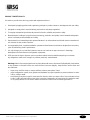 4
4
-
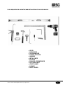 5
5
-
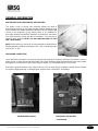 6
6
-
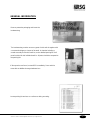 7
7
-
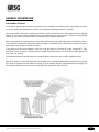 8
8
-
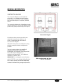 9
9
-
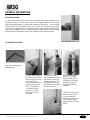 10
10
-
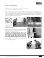 11
11
-
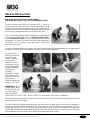 12
12
-
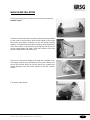 13
13
-
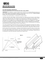 14
14
-
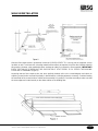 15
15
-
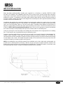 16
16
-
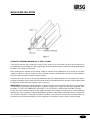 17
17
-
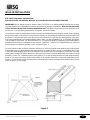 18
18
-
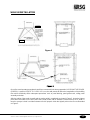 19
19
-
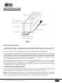 20
20
-
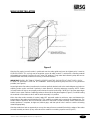 21
21
-
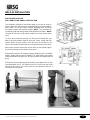 22
22
-
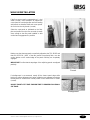 23
23
-
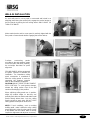 24
24
-
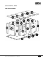 25
25
-
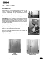 26
26
-
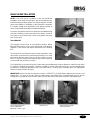 27
27
-
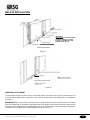 28
28
-
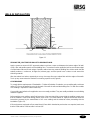 29
29
-
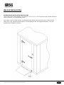 30
30
-
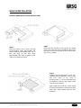 31
31
-
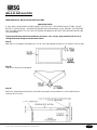 32
32
-
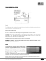 33
33
-
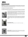 34
34
-
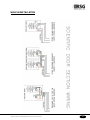 35
35
-
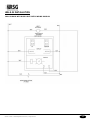 36
36
-
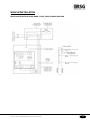 37
37
-
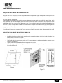 38
38
-
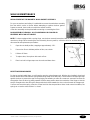 39
39
-
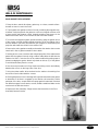 40
40
-
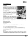 41
41
-
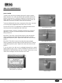 42
42
-
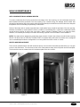 43
43
-
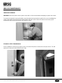 44
44
-
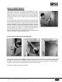 45
45
-
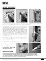 46
46
-
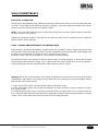 47
47
-
 48
48
-
 49
49
-
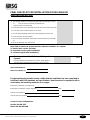 50
50
-
 51
51
-
 52
52
-
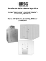 53
53
-
 54
54
-
 55
55
-
 56
56
-
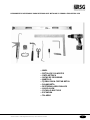 57
57
-
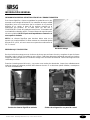 58
58
-
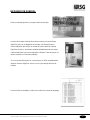 59
59
-
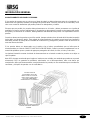 60
60
-
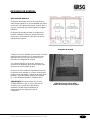 61
61
-
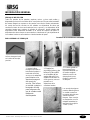 62
62
-
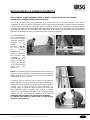 63
63
-
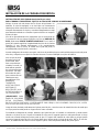 64
64
-
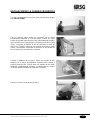 65
65
-
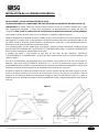 66
66
-
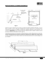 67
67
-
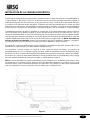 68
68
-
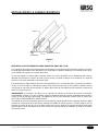 69
69
-
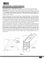 70
70
-
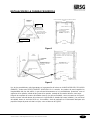 71
71
-
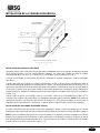 72
72
-
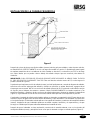 73
73
-
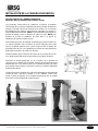 74
74
-
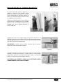 75
75
-
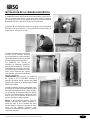 76
76
-
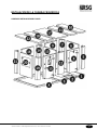 77
77
-
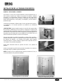 78
78
-
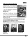 79
79
-
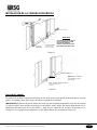 80
80
-
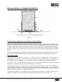 81
81
-
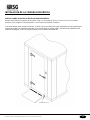 82
82
-
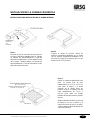 83
83
-
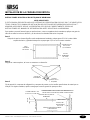 84
84
-
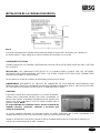 85
85
-
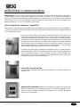 86
86
-
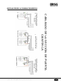 87
87
-
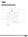 88
88
-
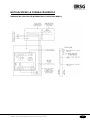 89
89
-
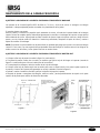 90
90
-
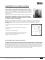 91
91
-
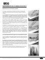 92
92
-
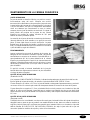 93
93
-
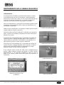 94
94
-
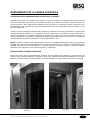 95
95
-
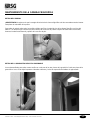 96
96
-
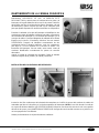 97
97
-
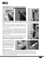 98
98
-
 99
99
-
 100
100
-
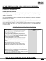 101
101
-
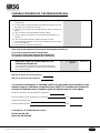 102
102
-
 103
103
-
 104
104


en otros idiomas
- English: Norlake Walk-in Installation guide
Artículos relacionados
Otros documentos
-
ESS EDM2 1600-50 Guía de instalación
-
 ESS XS-Z4M-P-1000 Guía de instalación
-
-
 IGNIA LIGHT STARRY SKY Installation and Maintenance Manual
-
 ESS EDCLEANCOMTAF-1900 Guía de instalación
-
 ESS EDMTAF900 Guía de instalación
-
 ESS R-LINE-900-P Guía de instalación
-
 ESS SEAL-BOX-LR Guía de instalación
-
Laserliner MoistureMaster Compact Plus El manual del propietario
-
Dimplex HMSF El manual del propietario


