koban KCM-RJ El manual del propietario
- Categoría
- Probadores de redes de cable
- Tipo
- El manual del propietario

Comprobador cables VDV
Instrucciones de Operación
Comprobador de cables VDV
KCM-RJ-0767493
Lea este manual antes de encender la unidad.
Información de seguridad importante en el interior.


3
Comprobador cables VDV
Contenido
1. Introducción ··································································································· 4
2. Especificaciones generales ············································································· 5
3. Descripción ···································································································· 6
3-1. Descripción del medidor ·································································· 6
3-2. Mando a distancia & ID ···································································· 7
3-3. Símbolos utilizados en la pantalla LCD ············································· 7
4. Operación······································································································· 9
4-1. Voz ································································································· 9
4-1-1. Uso del generador de tonos para rastrear una línea telefónica
······································································································· 10
4-1-2. Uso del generador de tonos para rastrear un conector de la
línea telefónica ·············································································· 11
4-1-3. Ejemplos de cableado y visualización para cable de voz ······ 11
4-2. Datos ······························································································ 13
4-2-1. Prueba de un cable de empalme de datos terminado con
conectores RJ45 ············································································· 13
4-2-2. Prueba de un cable de datos instalado ································ 14
4-3. Prueba de cable con blindaje ························································· 15
4-3-1. Uso del generador de tonos para rastrear un cable de datos···
······································································································· 15
4-3-2. Uso del generador de tonos para rastrear un conector del
cable de datos ················································································ 16
4-3-3. Identificación del cable en el cable de datos instalado ········ 17
4-3-4. Ejemplos de cableado y visualización para cable de datos ··· 18
4-4. Video ······························································································ 21
4-4-1. Prueba de cableado en el cable coaxial instalado ················ 21
4-4-2. Rastreo de tono en el cable coaxial ····································· 22
4-4-3. Rastreo de tono en el conector del cable coaxial ················· 23
4-4-4. Identificación del cable en el cable de video instalado ········ 24
4-4-5. Ejemplos de cableado y visualización para cable coaxial ····· 25
4-5. Reemplazo de batería ···································································· 25

4
Comprobador cables VDV
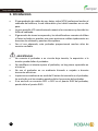
1. Introducción
• El comprobador de cables de voz, datos, video (VDV) profesional analiza el
cableado del teléfono, la red informática y los cables coaxiales en un solo
paso.
• La gran pantalla LCD retroiluminada muestra las conexiones y describe las
fallas de cableado.
• El generador de tonos incorporado y los identificadores remotos de Video
y Datos incluidos se pueden usar para posicionar cables rápidamente en
armarios de cableado y paneles de empalme.
• Con el uso adecuado, este probador proporcionará muchos años de
servicio confiable.
ADVERTENCIAS
• No conecte el probador a un circuito bajo tensión, la exposición a la
tensión puede dañar el probador.
• No modifique ni intente reparar el probador, no hay piezas reparables en
el interior.
• No use el probador en un ambiente húmedo o mojado o durante
tormentas eléctricas.
• Inspeccione visualmente un enchufe RJ antes de insertarlo en el probador,
los enchufes mal terminados pueden dañar los puertos del probador.
• Si se enchufa un conector RJ11 o RJ12 en el puerto RJ45 del probador,
puede dañar el puerto RJ45.

5
Comprobador cables VDV
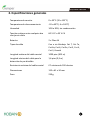
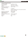
2. Especificaciones generales
Temperatura de servicio
0 a 50°C (32 a 122°F)
Temperatura de almacenamiento
-20 a 60°C (-4 a 140°F)
Humedad
10% a 90%, sin condensación
Tensión máxima entre cualquier dos
clavijas sin daño
60 V CC o 55 V CA
Baterías
2 x Pilas AA
Tipos de cable
Con o sin blindaje: Cat 7, Cat 7a,
Cat 6a, Cat 6, Cat 5e, Cat 5, Cat 4,
Cat 3, Coaxial
Longitud máxima del cable coaxial
1000 pies (305 m)
Longitud mínima del cable para la
detección de par dividido
1,6 pies (0,5 m)
Resistencia máxima del cable coaxial
CC máxima de 100 ohmios
Dimensiones
152 x 61 x 34 mm
Peso
230 g

6
Comprobador cables VDV
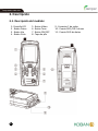
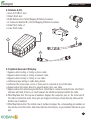
3. Descripción
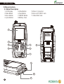
3-1. Descripción del medidor
1- Pantalla LCD
5 - Botón Video
9 - Conector F de video
2 - Botón Datos
6 - Botón Tono
10 - Puerto RJ11/RJ12 de voz
3 - Botón Voz
7 - Botón ON/OFF
11 - Puerto RJ45 de datos
4 - Botón Ciclo
8 - Tapa de pila

7
Comprobador cables VDV
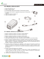
3-2. Mando a distancia & ID
1 - Puerto RJ11/RJ12 de voz
2 - Puerto 1-RJ45 de datos
3 - ID remoto RJ45, que permite mapear 5 ubicaciones remotas
4 - ID remoto del conector F, asignación de permisos 5 ubicaciones
remotas
5 - Cable de empalme de datos x 2
6 - Cable de empalme coaxial
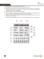
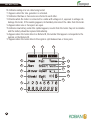
3-3. Símbolos utilizados en la pantalla LCD
1 - Aparece cuando se prueba o se entona un cable telefónico.
2 - Aparece cuando se prueba o se entona un cable de red.
3 - Aparece cuando se prueba o se entona un cable coaxial.
4 - Indica el cableado adecuado en el cable que se está probando.
5 - Indica que las conexiones en uno o más pares están invertidas en uno de los cables.
6 - Aparece cuando el probador detecta un alambre cruzado correctamente cableado.
7 - Aparece cuando el cable que se está probando tiene un blindaje que está conectado en
ambos extremos, el indicador de Blindaje parpadeará si hay un cortocircuito entre el
blindaje y cualquier alambre dentro del cable.
8 - Extremo cercano del diagrama de cableado: La fila superior de números muestra las
clavijas del conector en el extremo del probador del cable en orden numérico, estas
clavijas se mapean a las clavijas que se muestran directamente debajo de la fila inferior
de números.
9 - Extremo remoto del diagrama de cableado:
La fila inferior de números muestra el número de la clavija correspondiente en el
extremo remoto del cable, las líneas de puntos indican las clavijas en cortocircuito,
ningún número de la clavija indica un par abierto.
10 - Indica error de cableado en el cable que se está probando.

8
Comprobador cables VDV
11 - Aparece cuando se activa el generador de tonos.
12 - Indica que dos o más alambres están en cortocircuito entre sí.
13 - Parpadea cuando el probador está conectado a un cable bajo tensión, la exposición a la
tensión puede dañar el probador, si aparece esta advertencia, desconecte
inmediatamente el cable del probador.
14 - Aparece cuando uno o más pares están abiertos.
15 - Indica batería baja, cuando aparece este símbolo, los resultados del probador pueden
no ser confiables y la batería debe reemplazarse inmediatamente.
16 - Aparece cuando el probador detecta un ID remoto, el número que aparece corresponde
al número en el ID remoto.
17 - Aparece cuando el probador detecta que la señal está dividida entre dos o más pares.

9
Comprobador cables VDV
4. Operación
4-1. Voz
ADVERTENCIA: La exposición a la tensión puede dañar el probador, desconecte
inmediatamente el cable bajo prueba si la advertencia de Tensión aparece en la
pantalla. Asegúrese de que el cable no esté conectado a ningún dispositivo que
pueda suministrar tensión antes de reprobar. No conecte dos cables diferentes
en los puertos de prueba de Voz (RJ11/12) y de Datos (RJ45) al mismo tiempo.
Los cables interactuarán entre sí y alterarán los resultados de prueba.
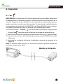
1. Presione el botón ON/OFF para encender el probador y luego presione
el botón Voz para seleccionar la función de prueba de alambre de voz.
2. Conecte un extremo del cable bajo prueba al puerto RJ11/RJ12 del probador.
3. Conecte el otro extremo del cable bajo prueba al puerto RJ11/RJ12 del mando
a distancia.
4. Interprete los resultados utilizando el cableado y muestre los ejemplos en la
Página 13.
Nota: La división puede aparecer en la pantalla cuando se prueban cables que
no tienen torsión en los pares.
Mando a distancia

10
Comprobador cables VDV
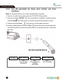
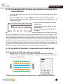
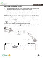
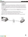
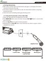
4-1-1. Uso del generador de tonos para rastrear una línea
telefónica
Nota: Es necesario utilizar una sonda amplificadora separada.
1. Conecte el cable bajo prueba al puerto RJ11/RJ12 del probador.
2. Presione el botón ON/OFF para encender el probador y luego presione
el botón Voz para seleccionar la función de prueba de alambre de voz.
3. Presione el botón Tono para activar el Generador de tonos.
4. Presione repetidamente el botón Tono para seleccionar el tono deseado.
Consulte la gráfica de secuencia para obtener una explicación de la selección
de tonos.
Sonda amplificadora
Modo
PRUEBA
Modo TONO Lo
Modo TONO HI 1
Modo TONO HI 2
Lo:
Tono de baja
frecuencia
HI 1:
Tono alterno de
alta/baja
frecuencia
HI 2:
Tono de gorjeo

11
Comprobador cables VDV
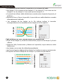
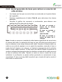
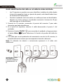
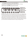
4-1-2. Uso del generador de tonos para rastrear un conector de la
línea telefónica
• Las clavijas del conector por las que se envía el tono se mostrarán en la parte inferior
de la pantalla.
• Presione repetidamente el botón Ciclo ► para seleccionar las clavijas deseadas.
• Consulte la gráfica de secuencia a continuación para obtener una explicación de la
selección de clavijas.
El tono se enviará a través de la clavija
seleccionada
El tono se enviará a través del par
seleccionado
El tono se enviará a través de todas las
6 clavijas
Nota: Cuando se rastrea un tendido de cable desde el generador de tonos hasta el extremo
del cable, la aplicación del tono en una sola clavija permitirá que el tono se detecte a una
mayor distancia del cable. Cuando se intenta ubicar un cable en una sala de equipos o en un
panel de empalme, enviando el tono a través de las 8 clavijas o un solo par, se limitará la
propagación de la señal de tonos a otros cables cercanos. El tono será más fuerte cuando la
punta de la sonda se coloque directamente sobre los alambres a través de los cuales se envía
el tono al extremo del cable. Cuando se envía un tono a través de un par individual, la
verificación se puede realizar poniendo en cortocircuito el par sospechoso. El tono será muy
débil cuando el par a través del cual se envía el tono esté en cortocircuito.
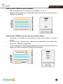
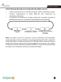
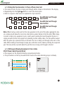
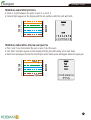
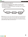
4-1-3. Ejemplos de cableado y visualización para cable de voz
Cable telefónico de USOC adecuadamente cableado
• Aparece Pasar en la pantalla, lo que indica un cable adecuadamente cableado.
• Los números de las clavijas en la fila superior e inferior son los mismos, lo que indica
una continuidad adecuada.
Cable telefónico con cableado cruzado de USOC adecuadamente cableado

12
Comprobador cables VDV
• Un alambre cruzado invierte la conexión en un extremo del cable.
• Las clavijas 1, 6 se cruzan con las clavijas 6, 1, las clavijas 2, 5 se cruzan con las
clavijas 5, 2 y las clavijas 3, 4 se cruzan con las clavijas 4, 3.
• A menudo se utilizan cables alámbricos cruzados entre el puerto de pared y el
teléfono.
• Aparecen Pasar y Rev en la pantalla, lo que indica un cable alámbrico cruzado
adecuadamente cableado.
• Los números de las clavijas en la fila inferior indican la inversión
correspondiente a los miembros de las clavijas en la fila superior.
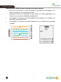
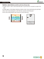
Cable telefónico de USOC con par abierto y en cortocircuito
• El par en las clavijas 3 y 4 está en cortocircuito y el par en las clavijas 1 y 6 está
abierto.
• Aparecen Falla, Cortocircuito y Abierto en la pantalla, lo que indica un cable
defectuoso.
• Las clavijas con errores de cableado parpadearán.
• Las líneas de puntos debajo de las clavijas 3 y 4 indican un par en cortocircuito.
• El espacio en blanco debajo de las clavijas 1 y 6 indica un par abierto.
Cortocircuito
PROBADOR
MANDO A DISTANCIA
PROBADOR
Abierto
MANDO A DISTANCIA

13
Comprobador cables VDV
4-2. Datos
ADVERTENCIA: La exposición a la tensión puede dañar el probador. Desconecte
inmediatamente el cable bajo prueba si la advertencia de Tensión aparece en la
pantalla. Asegúrese de que el cable no esté conectado a ningún dispositivo que
pueda suministrar tensión antes de reprobar. No conecte dos cables diferentes
en los puertos de prueba de Voz (RJ11/12) y de Datos (RJ45) al mismo tiempo.
Los cables interactuarán entre sí y alterarán los resultados de prueba.
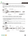
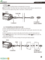
4-2-1. Prueba de un cable de empalme de datos terminado con
conectores RJ45
1. Presione el botón ON/OFF para encender el probador y luego presione
el botón Datos para seleccionar la función de prueba de alambre de
datos.
2. Conecte un extremo del cable bajo prueba al puerto RJ45 del probador.
3. Conecte el otro extremo del cable bajo prueba al puerto RJ45 del mando a
distancia.
4. Interprete los resultados utilizando los ejemplos de cableado y visualización
en la página 14.
Mando a distancia

14
Comprobador cables VDV
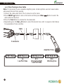
4-2-2. Prueba de un cable de datos instalado
1. Conecte un cable de empalme en buen estado a la pared o al panel de
empalme del cable que se está probando.
2. Conecte el otro extremo del cable de empalme al puerto RJ45 del probador.
3. Conecte otro cable de empalme en buen estado al puerto RJ45 del mando a
distancia.
4. Conecte el otro extremo del cable de empalme al puerto de pared o al panel
de empalme en el otro extremo del cable que se está probando.
5. Presione el botón ON/OFF para encender el probador y luego presione
el botón Datos para seleccionar la función de prueba de alambre
de datos.
6. Interprete los resultados de la prueba utilizando los ejemplos de visualización
y cableado que se muestran en las páginas 19 y 20.
Cable de empalme
Mando a distancia
Cable de
empalme

15
Comprobador cables VDV
4-3. Prueba de cable con blindaje
• Cuando se prueba un cable con blindaje, el indicador de Blindaje aparecerá en la
pantalla si el blindaje está conectado en ambos extremos del cable.
• Si el blindaje tiene un cortocircuito con un alambre dentro del cable, el indicador de
Blindaje y la clavija en cortocircuito correspondiente parpadearán.
• Aparecerá una marca de guión debajo de la clavija intermitente, lo que indica un
cortocircuito.
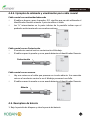
4-3-1. Uso del generador de tonos para rastrear un cable de datos
1. Conecte el cable bajo prueba al puerto RJ45 del probador.
2. Presione el botón ON/OFF para encender el probador, luego presione el botón Datos
para seleccionar la función de prueba de alambre de datos.
3. Presione el botón Tono para conmutar al generador de tonos.
4. Presione repetidamente el botón Tono para seleccionar el tono deseado. Consulte la
gráfica de secuencia para obtener la explicación de la selección de tonos.
Sonda amplificadora
Modo
PRUEBA
Modo TONO
Lo
Modo TONO HI
1
Modo TONO HI 2
Lo:
Tono de baja
frecuencia
HI 1:
Tono alterno de
alta/baja
frecuencia
HI 2:
Tono de gorjeo

16
Comprobador cables VDV
4-3-2. Uso del generador de tonos para rastrear un conector del
cable de datos
• Las clavijas por las que se envía el tono se mostrarán en la parte inferior
de la pantalla.
• Presione repetidamente el botón Ciclo ► para seleccionar las clavijas
deseadas.
• Consulte la gráfica de secuencia a continuación para obtener una
explicación de la selección de clavijas.
El tono se enviará a
través de la clavija
seleccionada
El tono se enviará a
través del par
seleccionado
El tono se enviará a
través de todas las 8
clavijas
Nota: Cuando se rastrea un tendido de cable desde el generador de tonos hasta
el extremo del cable, la aplicación del tono en una sola clavija permitirá que el
tono se detecte a una mayor distancia del cable. Cuando se intenta ubicar un
cable en una sala de equipos o en un panel de empalme, enviando el tono a
través de las 8 clavijas o un solo par, se limitará la propagación de la señal de
tonos a otros cables cercanos. El tono será más fuerte cuando la punta de la
sonda se coloque directamente sobre los alambres a través de los cuales se envía
el tono al extremo del cable. Cuando se envía un tono a través de un par
individual, la verificación se puede realizar poniendo en cortocircuito el par
sospechoso. El tono será muy débil cuando el par a través del cual se envía el
tono esté en cortocircuito.

17
Comprobador cables VDV
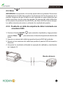
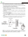
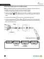
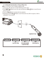
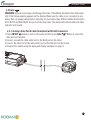
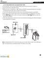
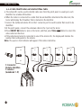
4-3-3. Identificación del cable en el cable de datos instalado
• Los ID remotos se pueden utilizar para identificar los tendidos de cables desde
el panel de empalme hasta un puerto de pared.
• Cada identificador tiene un número de ID etiquetado.
• Cuando el probador está conectado a un cable que tiene un identificador
adjunto en el otro extremo, el probador mostrará el número de ID que está
marcado en el identificador.
1. Conecte los ID remotos numerados al puerto de cada cable que deba
identificarse.
2. En el armario de cableado o panel de empalme, conecte el cable desconocido
al puerto RJ45 del probador.
3. Presione el botón ON/OFF para encender el probador y luego presione
el botón Datos para seleccionar la función de prueba de alambre de
datos.
4. Si el cable que se está probando está conectado a uno de los ID remotos, la
pantalla indicará el número que corresponde al mando a distancia
Nota: Los ID remotos RJ45 no prueban el cableado del cable. Solo el mando a
distancia puede identificar fallas de cableado. Es posible que el mando a
distancia no identifique el cable si el cable está mal cableado.
Placa de pared
Panel de empalme
ID remoto
ID remoto RJ45:
5 mandos a distancia
(Numerados del 1 al 5)
Probador

18
Comprobador cables VDV
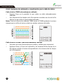
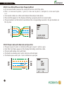
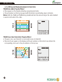
4-3-4. Ejemplos de cableado y visualización para cable de datos
Cable de datos T568B adecuadamente cableado
• Aparece Pasar en la pantalla, lo que indica un cable adecuadamente
cableado.
• Los números de las clavijas en la fila superior coinciden con los de la fila
inferior, lo que indica la continuidad adecuada.
Notas: Tanto el criterio de cableado T568A como el T568B probarán lo mismo
siempre que se utilice el mismo criterio en ambos extremos del cable.
Cable de datos cruzado T568B adecuadamente cableado
• Los pares se cruzan (transmiten para recibir y reciben para transmitir).
• Aparecen Pasar y X-over en la pantalla y los números de las clavijas en la
fila inferior indican el cruce correspondiente a los números de las clavijas
en la fila superior.
PROBADOR
MANDO A DISTANCIA
PROBADOR
MANDO A DISTANCIA

19
Comprobador cables VDV
Cable de datos T568B con pares divididos
• Hay una división entre los pares en las clavijas 3, 4 y 5, 6.
• Aparecen Falla y División en la pantalla y los números de las clavijas con la
división parpadearán.
Cable de datos T568B con un par en cortocircuito y abierto
• Las clavijas 1 y 2 están en cortocircuito y el par de las clavijas 7 y 8 está
abierto.
• Aparecen Falla, Cortocircuito y Abierto en la pantalla y las clavijas con
errores de cableado parpadearán.
• Las líneas de puntos aparecerán debajo de las clavijas en cortocircuito y el
espacio en blanco aparecerá debajo del par abierto.
Abierto
Cortocircuito
PROBADOR
MANDO A DISTANCIA
PROBADOR
MANDO A DISTANCIA

20
Comprobador cables VDV
Cable de datos T568B con par invertido y conexión cruzada
• El par en las clavijas 1 y 2 está invertido y los cables en las clavijas 5 y 6
están cruzados en un extremo del cable.
• Aparecerá Falla en la pantalla, lo que indica un cable defectuoso, las
clavijas con errores de cableado parpadearán.
• Las clavijas 2 y 1 que se muestran debajo de las clavijas 1 y 2 indican una
inversión en el par Naranja.
• Las clavijas 6 y 5 que se muestran debajo de 5 y 6 indican una conexión
cruzada.
PROBADOR
MANDO A DISTANCIA

21
Comprobador cables VDV
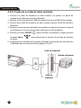
4-4. Video
Prueba de cableado en los cables de empalme coaxiales terminados con conectores F.
Nota: Es posible que las señales de prueba en el modo Video no pasen por un divisor. Solo
se puede conectar un ID remoto a la vez cuando se prueban cables conectados a un divisor
común.
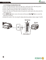
4-4-1. Prueba de cableado en el cable coaxial instalado
1. Conecte un cable de empalme en buen estado al conector F del probador.
2. Conecte el otro extremo del cable de empalme al puerto de pared o al panel de empalme
conectado al cable bajo prueba.
3. Conecte un mando a distancia coaxial numerado al puerto de pared en el otro extremo
del cable bajo prueba.
4. Presione el botón ON/OFF para encender el probador y luego presione el botón
Video para seleccionar la función de prueba del cable de video.
5. Interprete los resultados de la prueba a través de observar los ejemplos de cableado y
visualización.
Probador
Probador
Conector F
Conector F
Identificador remoto
del conector F
Identificador remoto
del conector F
Cable coaxial
Cable

22
Comprobador cables VDV
4-4-2. Rastreo de tono en el cable coaxial
Nota: Es necesario utilizar una sonda amplificadora separada. Algunos divisores
utilizados en los cables coaxiales evitarán que pase el tono.
1. Conecte el cable bajo prueba al conector F del probador.
2. Presione el botón ON/OFF para encender el probador y luego presione
el botón Video para seleccionar la función de prueba del cable de
video.
3. Presione el botón Tono para activar el generador de tonos.
4. Presione repetidamente el botón Tono para seleccionar el tono deseado,
consulte la gráfica de secuencia a continuación para obtener una explicación
de la selección de tonos.
Sonda amplificadora
Cable
Conector F
Modo
PRUEBA
Modo TONO Lo
Modo TONO HI 1
Modo TONO HI 2
Lo:
Tono de baja
frecuencia
HI 1:
Tono alterno de
alta/baja
frecuencia
HI 2:
Tono de gorjeo

23
Comprobador cables VDV
4-4-3. Rastreo de tono en el conector del cable coaxial
• El tono se puede enviar a través del conductor central, el blindaje o ambos.
• Presione repetidamente el botón Ciclo ► para seleccionar los
conductores deseados.
• La selección se mostrará en la parte inferior de la pantalla; consulte la
gráfica de secuencia a continuación para obtener una explicación.
Nota: Si se aplica el tono en el conductor central y el blindaje o solo el blindaje,
se permitirá que el tono se detecte a una mayor distancia del cable. Cuando se
intenta identificar un cable en presencia de múltiples cables, enviando el tono a
través del conductor central, limitará la propagación de la señal a otros cables.
El cable que se está entonando se puede identificar a través de tocar la punta de
la sonda con el conductor central en el extremo del cable.
Blindaje
Conductor central
Conductor central y
blindaje

24
Comprobador cables VDV
4-4-4. Identificación del cable en el cable de video instalado
• Los ID remotos se pueden usar para identificar tendidos de cables desde
el panel de empalme hasta un puerto de pared, cada identificador tiene
un número de ID etiquetado.
• Cuando el probador está conectado a un cable que tiene un identificador
adjunto en el otro extremo, el probador mostrará el número de ID que
está marcado en el identificador.
1. Conecte los ID remotos numerados al puerto del conector F para cada
ubicación que deba identificarse.
2. En el panel de empalme, conecte el cable desconocido al puerto F del
probador.
3. Presione el botón ON/OFF para encender el probador y luego presione
el botón Video para seleccionar la función de prueba del cable de
video.
4. Si el cable que se está probando está conectado a uno de los ID remotos, la
pantalla indicará el número que corresponde al mando a distancia.
Nota: El indicador de abierto o cortocircuito aparecerá si el cable está
defectuoso.
Identificador remoto
del conector F:
5 mandos a distancia
(numerados del 1 al
5)

25
Comprobador cables VDV
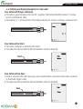
4-4-5. Ejemplos de cableado y visualización para cable coaxial
Cable coaxial con continuidad adecuada
• El cable es bueno y pasa la prueba, ID 1 significa que se está utilizando el
Identificador Remoto número 1 para terminar el cable.
• Las "o" intermitentes en la parte inferior de la pantalla indican que el
probador está ejecutando una prueba continua.
Cable coaxial con un Cortocircuito
• El conductor central está en cortocircuito al blindaje.
• El cable no pasa la prueba y no se puede detectar el identificador Remoto.
Cable coaxial con un Abierto
• Hay una rotura en el cable que provoca un circuito abierto. Una conexión
rota en el conductor central o en el blindaje provocará una falla.
• El cable no pasa la prueba y no se puede detectar el identificador Remoto.
4-5. Reemplazo de batería
1. Baje la pestaña de bloqueo y abra la puerta de batería.
Cortocircuito
Abierto

26
Comprobador cables VDV
2. Reemplace las 2 x pilas AA.
3. Remonte el medidor.
Nota: No opere el probador con la tapa de batería retirada.

Operating Instruction for
VDV Wire Tester
Please read this manual before switching the unit on.
Important safety information inside.
KCM-RJ - 0767493


3
VDV Wire Tester
Page
4
5
6
6
7
7
9
9
10
11
11
13
13
14
15
15
16
17
18
21
21
22
23
24
25
26
Content
1.Introduction..............................................................................................
2.General Specifications..............................................................................
3.Description...............................................................................................
3-1.Meter Description................................................................................
3-2.Remote & ID’s......................................................................................
3-3.Symbols Used on LCD Display...............................................................
4. ..................................................................................................Operation
4-1. ...................................................................................................Voice
4-1-1.Using the Tone Generator to Trace a Phone Line...............................
4-1-2.Using the Tone Generator to Trace a Phone Line Cont.......................
4-1-3.Wiring and Display Examples for Voice Cable...................................
4-2.Data....................................................................................................
4-2-1.Testing a Data Patch Cable Terminated with RJ45 Connectors..........
4-2-2.Testing an Installed Data Cable.......................................................
4-3.Testing Shielded Cable.........................................................................
4-3-1.Using the Tone Generator to Trace a Data Cable...............................
4-3-2.Using the Tone Generator to Trace a Data Cable Cont.......................
4-3-3.Cable Identification on Installed Data Cable....................................
4-3-4.Wiring and Display Examples for Data Cable....................................
4-4.Video...................................................................................................
4-4-1.Testing Wiring on Installed Coax Cable............................................
4-4-2.Tone Tracing on Coax Cable.............................................................
4-4-3.Tone Tracing on Coax Cable Cont.....................................................
4-4-4.Cable Identification on Installed Video Cable...................................
4-4-5.Wiring and Display Examples for Coax Cable....................................
4-5.Battery Replacement...........................................................................

4
VDV Wire Tester
1.Introduction
• The Professional VDV Wire Tester analyzes wiring on phone, computer network and coax cables
in one easy step.
• The large backlit LCD display maps out connections and describes wiring faults.
• The built-in tone generator and the included Video and Data remote identifiers can be used to
quickly locate cables in wiring closets and patch panels.
• With proper use, this tester will provide many years of reliable service.
WARNINGS
• Do not connect the tester to a live circuit, exposure to voltage can damage the tester.
• Do not modify or try to repair the tester, no serviceable parts are inside.
• Do not use the tester in a wet or damp environment or during electrical storms.
• Visually inspect an RJ plug before inserting it into the tester, poorly terminated plugs may damage
the jacks on the tester.
• Plugging an RJ11 or RJ12 connector into the RJ45 jack on the tester may damage the RJ45 jack.

5
VDV Wire Tester
2.General Specifications
Operating Temperature
Storage Temperature
Humidity
Maximum Voltage Between any
two Pins Without Damage
Batteries
Cable Types
Maximum Coax Cable Length
Minimum Cable Length for
Split Pair Detection
Maximum Coax Cable Resistance
Dimensions
Weight
0 to 50°C (32 to 122°F)
-20 to 60°C (-4 to 140°F)
10% to 90%, non-condensing
60V DC or 55V AC
2 x AA Battery
Shielded or Unshielded: Cat 7, Cat 7a, Cat 6a, Cat 6, Cat 5e,
Cat 5, Cat 4, Cat 3, Coax
1000 feet (305m)
1.6 feet (0.5m)
100 ohms maximum DC
152 x 61 x 34 mm
230g

6
VDV Wire Tester
3.Description
3-1.Meter Description
1-LCD Display
2-DataButton
3-VoiceButton
4-Cycle uttonB
1
2
3
4
5
6
7
8
9
10
11
9-Video-F-Connector
10-Voice-RJ11/RJ12 Jack
11-Data-RJ45 Jack
5-Video uttonB
6-Tone uttonB
7-ON/OFF uttonB
8-Battery Cover

1
2
7
VDV Wire Tester
3-2.Remote & ID’s
1-Voice-RJ11/RJ12 Jack
2-Data1-RJ45 Jack
3-RJ45 Remote ID’s, Permit Mapping 5 Remote Locations
4-F-Connector Remote ID’s, Permit Mapping 5 Remote Locations
5-Data Patch Cable x 2
6-Coax Patch Cable
3-3.Symbols Used on LCD Display
1- .Appears when testing or toning a phone cable
2- .Appears when testing or toning a network cable
3- .Appears when testing or toning a coax cable
4-Indicates proper wiring on cable being tested.
5-Indicates the connections on one or more pairs is reversed at one of the cable.
6-Appears when the tester detects a properly wired cross over cable.
7-Appears when the cable being tested has a shield that is connected at both ends, the Shield
indicator will flash if there is a short between the shield and any wire within the cable.
8-Wire Map Near End: The top row of numbers displays the connector pins on the tester end of
the cable in numerical order, these pins are mapped to the pins shown directly below on the
bottom row of numbers.
9-Wire Map Remote End: The bottom row of numbers displays the corresponding pin numbers on
the remote end of the cable, dash lines indicate shorted pins, no pin numbers indicate an open
pair.
3
4
5
6

8
VDV Wire Tester
10-Indicates wiring error on cable being tested.
11- .Appears when the tone generator is activated
12-Indicates that two or more wires are shorted to each other.
13-Flashes when the tester is connected to a cable with voltage on it, exposure to voltage can
damage the tester, if this warning appears, immediately disconnect the cable from the tester.
14-Appears when one or more pairs are open.
15-Indicates low battery, when this symbol appears, results from the tester may not be reliable
and the battery should be replaced immediately.
16-Appears when the tester detects a Remote ID, the number that appears corresponds to the
number on the Remote ID.
17-Appears when the tester detects the signal is split between two or more pairs.
1 2 3
4
5
6
10
7
8
9
11
12
13
14
15
16
17

9
VDV Wire Tester
4.Operation
4-1.Voice
WARNING: Exposure to voltage can damage the tester, immediately disconnect the cable under
test if the Voltage warning appears on the display. Make sure the cable is not connected to any
device that can supply voltage before retesting. Do not connect two different cables into the Voice
(RJ11/12) and Data (RJ45) test ports at the same time. The cables will interact with each other and
alter test results.
1.Press ON/OFF Button to turn on the tester and then press Voice Button to select the voice
wire test function.
2.Connect one end the cable under test to the RJ11/RJ12 port on the tester.
3.Connect the other end of the cable under test to the RJ11/RJ12 port on the remote.
4.Interpret the results using the wiring and display examples on Page 13.
Note: Split may appear on the display when testing cables that have no twisting on the pairs.
Remote

10
VDV Wire Tester
4-1-1.Using the Tone Generator to Trace a Phone Line
Note: It is necessary to use a separate amplifier probe.
1.Connect the cable under test to the RJ11/RJ12 port on the tester.
2.Press ON/OFF Button to turn on the tester and then press Voice Button to select the voice
wire test function.
3.Press the Tone Button to activate the Tone Generator.
4.Repeatedly press the Tone Button to select the desired tone, Refer to sequence chart for
explanation of tone selection.
Lo:
Low Pitch Tone
HI 1:
Alternating High/
Low Pitch Tone
HI 2:
Warbling Tone
TEST Mode TONE Mode Lo TONE Mode HI 1 TONE Mode HI 2
Amplifier Probe

1 6 2 5 3 4
1
1
2
2
3
3
4
4
5
5
6
6
Tone Will Be Sent Through
Selected Pin
Tone Will Be Sent Through
Selected Pair
Tone Will Be Sent Through
All 6 Pins
11
VDV Wire Tester
4-1-2.Using the Tone Generator to Trace a Phone Line Cont
• The connector pins the tone is being sent through will be shown on the bottom of the display.
• Repeatedly press the Cycle Button to select the desired pins.
• Refer to sequence chart below for explanation of pin selection.
Note: When tracing a cable run from the tone generator to the end of the cable, applying the tone
on a single pin will allow the tone to be detected at a greater distance from the cable. When trying
to locate a cable in an equipment room or patch panel, sending the tone through all 8 pins or a
single pair will limit the tone signal from spreading to other nearby cables. The tone will be loudest
when the probe tip is placed directly on the wires the tone is being sent through at the end of the
cable. When sending a tone through a single pair, verification can be made by shorting the suspected
pair. The tone will be very faint when the pair the tone is being sent through is shorted.
4-1-3.Wiring and Display Examples for Voice Cable
USOC Phone Cable Properly Wired
• Pass appears on the display indicating a properly wired cable.
• The pin numbers on the top row and bottom row are the same indicating proper continuity.
TESTER
REMOTE
1
2
3
4
5
6
1
2
3
4
5
6

12
VDV Wire Tester
USOC Cross Wired Phone Cable Properly Wired
• A cross wired cable reverses the connection at one end of the cable.
• Pins 1, 6 cross over to pins 6, 1, pins 2, 5 cross over to pins 5, 2, and pins 3, 4 cross over to pins
4, 3.
• Cross wired cables are often used between the wall port and phone.
• Pass and Rev appear on the display indicating a properly wired cross wired cable.
• The pin numbers on the bottom row indicate the corresponding reversal to the pin members on
the top row.
USOC Phone Cable with Shorted and Open Pair
• The pair on pins 3 and 4 is shorted and the pair on pins 1 and 6 is open.
• Fail, Short and Open appear on the display indicating a defective cable.
• The pins with wiring errors will flash.
• The dash lines below pins 3 and 4 indicate a shorted pair.
• The blank space under pins 1 and 6 indicate an open pair.
TESTER
REMOTE
1
2
3
4
5
6
1
2
3
4
5
6
Open
Short
TESTER
1
2
3
4
5
6
REMOTE
1
2
3
4
5
6

13
VDV Wire Tester
4-2.Data
WARNING: Exposure to voltage can damage the tester. Immediately disconnect the cable under
test if the Voltage warning appears on the display. Make sure the cable is not connected to any
device that can supply voltage before retesting. Do not connect two different cables into the Voice
(RJ11/RJ12) and Data (Rj45) test ports at the same time. The cables will interact with each other
and alter test results.
4-2-1.Testing a Data Patch Cable Terminated with RJ45 Connectors
1.Press ON/OFF Button to turn on the tester and then press Data Button to select the
data wire test function.
2.Connect one end the cable under test to the RJ45 port on the tester.
3.Connect the other end of the cable under test to the RJ45 port on the remote.
4.Interpret the results using the wiring and display examples on page 14.
Remote

14
VDV Wire Tester
4-2-2.Testing an Installed Data Cable
1.Connect a known good patch cable to the wall port or patch panel of the cable being tested.
2.Connect the other end of the patch cable to the RJ45 port on the tester.
3.Connect another known good patch cable to the RJ45 port on the remote.
4.Connect the other end of the patch cable to the wall port or patch panel at the other end of the
cable being tested.
5.Press ON/OFF Button to turn on the tester and then press Data Button to select the
data wire test function.
6.Interpret the results of the test using the display and wiring examples shown on page 19 and 20.
Patch Cable
Remote
Patch Panel

15
VDV Wire Tester
4-3.Testing Shielded Cable
• When testing a shielded cable, the Shield indicator will appear on the display if the shield is
connected at both ends of the cable.
• If the shield is shorted to a wire within the cable, the Shield indicator and the corresponding
shorted pin will flash.
• A dash mark under the flashing pin will appear indicating a short.
4-3-1.Using the Tone Generator to Trace a Data Cable
1.Connect the cable under test to the RJ45 port on the tester.
2.Press ON/OFF Button to turn on the tester, then press Data Button to select the data
wire test function.
3.Press the Tone Button to switch to the Tone Generator.
4.Repeatedly press the Tone Button to select the desired tone, Refer to sequence chart for
explanation tone selection.
Amplifier Probe
Lo:
Low Pitch Tone
HI 1:
Alternating High/
Low Pitch Tone
HI 2:
Warbling Tone
TEST Mode TONE Mode Lo TONE Mode HI 1 TONE Mode HI 2

16
VDV Wire Tester
4-3-2.Using the Tone Generator to Trace a Data Cable Cont
• The pins the tone is being sent through will be shown on the bottom of the display.
• Repeatedly press the Cycle Button to select the desired pins.
• Refer to sequence chart below for explanation of pin selection.
Note: When tracing a cable run from the tone generator to the end of the cable, applying the tone
on a single pin will allow the tone to be detected at a greater distance from the cable. When trying
to locate a cable in an equipment room or patch panel, sending the tone through all 8 pins or a
single pair will limit the tone signal from spreading to other nearby cables. The tone will be loudest
when the probe tip is placed directly on the wires the tone is being sent through at the end of the
cable. When sending a tone through a single pair, verification can be made by shorting the suspected
pair. The tone will be very faint when the pair the tone is being sent through is shorted.
1
1
2
2
3
3
4
4
5
5
678
678
1 2 3 6 4 5 7 8
Tone Will Be Sent
Through Selected Pin
Tone Will Be Sent
Through Selected Pair
Tone Will Be Sent
Through All 8 Pins

17
VDV Wire Tester
4-3-3.Cable Identification on Installed Data Cable
• The remote ID’s can be used to identify cable runs from the patch panel to a wall port.
• Each identifier has a labeled ID number.
• When the tester is connected to a cable that has an identifier attached at the other end, the tester
will display the ID number that is marked on the identifier.
1.Connect the numbered remote ID’s to the port for each cable that needs to be identified.
2.At the wiring closet or patch panel, connect the unknown cable to the RJ45 port on the tester.
3.Press ON/OFF Button to turn on the tester and then press Data Button to select the
data wire test function.
4.If the cable being tested is connected to one of the remote ID’s,the display will indicate the number
that corresponds to the remote.
Note: The RJ45 remote ID’s do not test the wiring on the cable. Only the remote can identify wiring
faults. The remote may not identify the cable if the cable is miss-wired.
Tester
Patch Panel
Remote ID
3
Wall Plate
RJ45 Remote ID:
5 remotes
(Numbered 1- 5)

18
VDV Wire Tester
4-3-4.Wiring and Display Examples for Data Cable
T568B Data Cable Properly Wired
• Pass appears on the display indicating a properly wired cable.
• The pin numbers on the top row agree with the bottom row indicating proper continuity.
Notes: Both the T568A and T568B wiring standard will test the same as long as the same standard
is used on both ends of the cable.
T568B Cross Over Data Cable Properly Wired
• The pairs cross over (transmit to receive and receive to transmit).
• Pass and X-over appear on the display and the pin numbers on the bottom row indicate the
corresponding cross over to the pin numbers on the top row.
1
2
3
4
5
6
7
8
1
2
3
4
5
6
7
8
TESTER
REMOTE
1
2
3
4
5
6
7
8
1
2
3
4
5
6
7
8
TESTER
REMOTE

1
2
3
4
5
6
7
8
1
2
3
4
5
6
7
8
TESTER
REMOTE
Open
Short
19
VDV Wire Tester
T568B Data Cable With Split Pairs
• There is a split between the pairs on pins 3, 4 and 5, 6.
• Fail and Split appear on the display and the pin numbers with the split will flash.
T568B Data Cable With a Shorted and Open Pair
• Pins 1 and 2 are shorted and the pair on pins 7 and 8 is open.
• Fail, Short and Open appear on the display and the pins with wiring errors will flash.
• Dash lines will appear below the shorted pins and a blank space will appear below the open pair.
1
2
3
4
5
6
7
8
1
2
3
4
5
6
7
8
TESTER
REMOTE

20
VDV Wire Tester
T568B Data Cable With Reversed Pair and Crossed Connection
• The pair on pins 1 and 2 is reversed and the wires on pins 5 and 6 are crossed at one end of the
cable.
• Fail will appear on the display indicating a defective cable, the pins with wiring errors will flash.
• Pins 2 and 1 shown below pins 1 and 2 indicate a reversal on the Orange pair.
• Pins 6 and 5 shown below 5 and 6 indicate a crossed connection.
1
2
3
4
5
6
7
8
1
2
3
4
5
6
7
8
TESTER
REMOTE

21
VDV Wire Tester
4-4.Video
Testing Wiring on Coax Patch Cables Terminated with F Connectors.
Note: Test signals in the Video mode may not pass through a splitter. Only one remote ID can be
connected at a time when testing cables connected to a common splitter.
4-4-1.Testing Wiring on Installed Coax Cable
1.Connect a known good patch cable to the F connector on the tester.
2.Connect the other end of the patch cable to the wall port or patch panel connected to the cable
under test.
3.Connect a numbered coax remote to the wall port at the other end of the cable under test.
4.Press ON/OFF Button to turn on the tester and then press Video Button to select the
video cable test function.
5.Interpret the results of the test by looking at the wiring and display example.
Cable
Tester
F-Connector
Remote Identifier
F-Connector
Coax Cable
Tester
F-Connector
Remote Identifier
F-Connector

22
VDV Wire Tester
4-4-2.Tone Tracing on Coax Cable
Note: It is necessary to use a separate amplifier probe. Certain splitters used on Coaxial cables
will prevent the tone from passing.
1.Connect the cable under test to the F connector on the tester.
2.Press ON/OFF Button to turn on the tester and then press Video Button to select the
video cable test function.
3.Press the Tone Button to activate the Tone Generator.
4.Repeatedly press the Tone Button to select the desired tone, refer to sequence chart below
for explanation of tone selection.
Cable
F-Connector
Amplifier Probe
Lo:
Low Pitch Tone
HI 1:
Alternating High/
Low Pitch Tone
HI 2:
Warbling Tone
TEST Mode TONE Mode Lo TONE Mode HI 1 TONE Mode HI 2

23
VDV Wire Tester
4-4-3.Tone Tracing on Coax Cable Cont
• The tone can be sent through the center conductor, the shield or both.
• Repeatedly press the Cycle Button to select the desired conductors.
• The selection will be shown on the bottom of the display, refer to sequence
chart below for explanation.
Note: Applying the tone on the center conductor and the shield or just the shield will allow the
tone to be detected at a greater distance from the cable. When trying to identify a cable in the
presence of multiple cables, sending the tone through just the center conductor will limit the
signal spreading to other cables. The cable that is being toned can be identified by touching the
probe tip to the center conductor at the end of the cable.
S
Shield
C
Center Conductor
CS
Center Conductor
and Shield

24
VDV Wire Tester
4-4-4.Cable Identification on Installed Video Cable
• The remote ID’s can be used to identify cable runs from the patch panel to a wall port, each
identifier has a labeled ID number.
• When the tester is connected to a cable that has an identifier attached at the other end, the
tester will display the ID number that is marked on the identifier.
1.Connect the numbered remote ID’s to the F connector port for each location that needs to be
identified.
2.At the patch panel, connect the unknown cable to the F port on the tester.
3.Press ON/OFF Button to turn on the tester, and then press Video Button to select the
video cable test function.
4.If the cable being tested is connected to one of the remote Id’s, the display will indicate the
number that corresponds to the remote.
Note: The open or short indicator will appear if the cable is defective.
1
1
2
3
4
5
F-Connector
Remote Identifier:
5 remotes
(numbered 1- 5)

25
VDV Wire Tester
4-4-5.Wiring and Display Examples for Coax Cable
Coax Cable with Proper Continuity
• The cable is good and passes the test, ID 1 signifies that Remote Identifier number 1 is being
used to terminate the cable.
• The flashing “o” s on the bottom of the display indicate the tester is running a continuous test.
Coax Cable with a Short
• The center conductor is shorted to the shield.
• The cable fails the test and the Remote Identifier cannot be detected.
Coax Cable with an Open
• There is a break in the cable causing an open circuit A broken connection in the center conductor
or shield will trigger a fault.
• The cable fails the test and the Remote Identifier cannot be detected.
Short
Open

26
VDV Wire Tester
4-5.Battery Replacement
1.Pull down locking tab, and open the battery door.
2.Replace the 2 x AA battery.
3.Re-assemble the meter.
Note: Do not operate the tester with the battery door removed.


Rev.200513
VDV Wire Tester
-
 1
1
-
 2
2
-
 3
3
-
 4
4
-
 5
5
-
 6
6
-
 7
7
-
 8
8
-
 9
9
-
 10
10
-
 11
11
-
 12
12
-
 13
13
-
 14
14
-
 15
15
-
 16
16
-
 17
17
-
 18
18
-
 19
19
-
 20
20
-
 21
21
-
 22
22
-
 23
23
-
 24
24
-
 25
25
-
 26
26
-
 27
27
-
 28
28
-
 29
29
-
 30
30
-
 31
31
-
 32
32
-
 33
33
-
 34
34
-
 35
35
-
 36
36
-
 37
37
-
 38
38
-
 39
39
-
 40
40
-
 41
41
-
 42
42
-
 43
43
-
 44
44
-
 45
45
-
 46
46
-
 47
47
-
 48
48
-
 49
49
-
 50
50
-
 51
51
-
 52
52
-
 53
53
-
 54
54


koban KCM-RJ El manual del propietario
- Categoría
- Probadores de redes de cable
- Tipo
- El manual del propietario
en otros idiomas
- English: koban KCM-RJ Owner's manual
Otros documentos
-
Klein Tools VDV501-809 Guía del usuario
-
Klein Tools VDV501-824 Instrucciones de operación
-
Klein Tools VDV501-222 Manual de usuario
-
Klein Tools VDV501-222 Manual de usuario
-
-
Ideal VDV PRO 33-770 Instructions Manual
-
-
-
Trendnet TC-NT3 Ficha de datos
-
Klein Tools M2O41038KIT Manual de usuario