LG LSUD1866HM Guía de instalación
- Tipo
- Guía de instalación

ENGLISH
ESPAÑOL
P/No. : 3828AR7142U
Le modŁl e "Froid et
chauffage" est ØquipÈ d'un
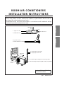
ROOM AIR CONDITIONERS
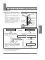
INSTALLATION INSTRUCTIONS
• Please read this instruction sheet completely before installing the product.
• When the power cord is wanted to replace, replacement work shall be
performed by authorized personnel only.
• Installation work must be performed in accordance with national wiring
standards by authorized personnel only.
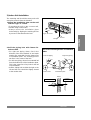
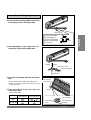
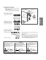
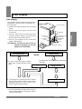
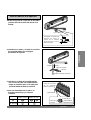
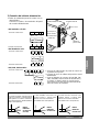
1. Type "A" screw
3. Type "B" screw
4. Holder Remote-Controller
2. Installation Plate
more than 5cm
1cm
5. Copper pipe (Liquid side)
6. Copper pipe (Gas side)
7. Power supply cord(power connecting cable)
8. Connecting cable(except 18K cooling only model)
more than
10cm
more than
10cm
more than
70cm
Cooling & Heating Model has
included Drain Elbow
more than
5cm

2 ENGLISH
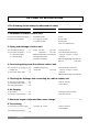
OUT-LINE OF INSTALLATION
Installation works
Installation Parts
Required Tools
2. Installation of indoor, outdoor Unit
1.The following should always be observed for safety
...................................................
3
1) Selection of the best location
...
4
2) Indoor unit Installation
..............
5
• Installation plate
• Four type "A" screws
• Connecting cable
• Level
• Screw driver
• Electric drill
• Hole core drill(ø70mm)
3. Piping and drainage of indoor unit
1) Preparation of pipings
............
6
2) Connection of pipings ......7~11
• For right rear piping
• For the left piping
• Pipes: Gas side
.............
1
/2",
5
/8"
Liquid side
.........
1
/4",
3
/8"
(different depending on model No.)
• Insulated drain hose
• Insulation materials
• Flaring tools set
• Specified torque wrenches
1.8 kg
.
m, 4.2 kg
.
m, 5.5 kg
.
m,
6.6 kg
.
m
(different depending on model No.)
Spanner
.........................
Half union
4. Connecting pipings and the cable to outdoor unit
1) Connection of pipings to the
outdoor unit
............................
12
2) Connection of the cable
.........
13
• Additional drain hose
(Outer Dia
.....................
15.5 mm)
• Specified torque wrenches
1.8 kg
.
m, 4.2 kg
.
m, 5.5 kg
.
m,
6.6 kg
.
m
(different depending on model No.)
5. Checking the drainage and connecting the cable to Indoor unit
1) Checking the drainage
..........
14
2) Connecting of the cable
.........
15
3) Forming the pipings
...............
16
• A glass of water
• Screw driver
6. Air Purging
7. Maximum length of pipe and freon extra change
...........................................................
19
1) Air Purging
............................
17
2) Checking a gas-leakage
........
18
• Hexagonal wrench (4mm)
• Gas-leak detector
8. Test running
1) Connection of power supply
...............................................
20
2) Evaluation performance
..............................................
20
• Tow type "B" screws • Owner's manual
• Thermometer

ENGLISH 3
ENGLISH
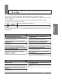
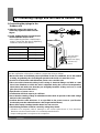
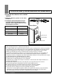
1. The following should be always be observed
for safety
• Please report to or take consent by the supply authority before connection to the system.
• Be sure to read "THE FOLLOWING SHOULD ALWAYS BE OBSERVED FOR SAFETY" before installing
the air conditioner.
• Be sure to observe the cautions specified here as they include important items related to safety.
• The indications and meanings are as follows.
• After reading this manual, be sure to keep it together with the instruction manual in a handy place on the
customer's site.
Could lead to death, serious injury, etc.
Do not install it yourself (customer).
Perform the installation securely referring to the
installation manual.
Install the unit securely in a place which can bear the
weight of the unit.
Perform electrical work according to the installation
manual and be sure to use an exclusive circuit.
Attach the electrical part cover to the indoor unit and the
service panel to the outdoor unit securely.
Be sure to use the part provided or specified parts for
the installation work.
Check that the refrigerant gas due not leak after
installation is completed.
Perform grounding
Do not install the unit in a place where an inflammable
gas leaks.
Perform the drainage/piping work securely according to
the installation manual.
Use the specified wires to connect the indoor and
outdoor units securely and attach the wires firmly to the
terminal board connecting sections so the stress of the
wires is not applied to the sections.
• Incomplete installation could cause injury due to fire, electric shock, the
unit falling or a leakage of water. Consult the dealer from whom you
purchased the unit or special installer.
• Incomplete installation could cause a personal injury due to fire,
electric shock, the unit falling or a leakage of water.
• When installed in an insufficient strong place, the unit could fall
causing injured.
• Incomplete connecting and fixing could cause fire.
• If the capacity of the power circuit is insufficient or there is incomplete
electrical work, it could result in a fire or an electric shock.
• The use of defective parts could cause an injury or leakage of water
due to a fire, electric shock, the unit falling, etc.
• If gas leaks and accumulates in the area surrounding the unit, it could
cause an explosion.
• If there is a defect in the drainage/piping work, water could
drop from the unit and household goods could be wet and
damaged.
• Do not connect the ground wire to a gas pipe, water pipe arrester or
telephone ground wire. Defective grounding could cause an electric shock.
• If the electrical part cover if the indoor unit and/or the service panel if
the outdoor unit are not attached securely, it could result in a fire or
electric shock due to dust, water, etc.
Could lead to serious injury in particular environments when operated incorrectly.
WARNING
WARNING
CAUTION
CAUTION

4 ENGLISH
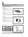
2. Installation of Indoor, Outdoor unit
A
B
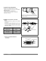
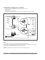
1) Selection of the best location
1. Indoor unit
2. Outdoor unit
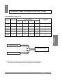
3.Piping length and the elevation
• There should not be any heat source or
steam near the unit.
• There should not be any obstacles to prevent
the air circulation.
• A place where air circulation in the room will
be good.
• A place where drainage can be easily
obtained.
• A place where noise prevention is taken into
consideration.
• Do not install the unit near the door way.
• Ensure the spaces indicated by arrows from
the wall, ceiling, fence, or other obstacles.
• If an awning is built over the unit to prevent
direct sunlight or rain exposure, be careful
that heat radiation from the condenser is not
restricted.
• There should not be any animals or plants
which could be affected by hot air
discharged.
• Ensure the spaces indicated by arrows from
the wall, ceiling, fence, or other obstacles.
More than
5 cm
More than 5 cm
More than
5 cm
More than eye-level
More than 10 cm
More than 10 cm
More than 70 cm
Indoor unit
Outdoor
unit
Pipe Size
MODEL
GAS LIQUID
Max.
length
A (m)
Max.
Elevation
B (m)
18K 1/2" 1/4" 30 15
24K, 26K 5/8" 1/4" 30 15
28K 5/8" 3/8" 30 15

ENGLISH 5
ENGLISH
A,B
A,B,C
C
D
D
5-7mm
A,B,D
C
A
B,D
C
ø70mm
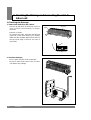
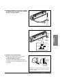
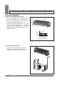
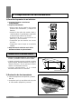
2) Indoor Unit Installation
The mounting wall should be strong and solid
enough to protect it from the vibration.
1.Mount the installation plate on the wall
with four Type "A" screws.
(if mounting the unit on the concrete wall,
consider using anchor bolts.)
• Always mount the Installation plate
horizontally by aligning the marking-off line
by means of the thread and a level.
2. Drill the piping hole with 70mm dia.
holecore drill.
• For right rear piping, draw a line in the
direction of the arrow marked "A" and make
another line extended from the bottom line
of installation plate. The meeting point of
two lines is the center of the hole.
• For left rear piping, draw a line extented left
from the bottom line of the installation plate.
This is the center line of any hole for the left
rear installation.
• Drill the Piping hole at either the right or the
left and the hole should be slightly slanted
to the outdoor side.
Type "A" screw
Installation Plate
marking-off line
Thread
Weight
The lower left and right side of Installation
Plate
Left rear piping
Right rear piping
Indoor
Hole Center
Installation plate
Outdoor
WALL

6 ENGLISH
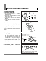
3. Piping and Drainage of Indoor Unit
1) Preperation of Pipings
1. Cut the pipes and the cable.
• Use the accessory piping kit or the pipes
purchased locally.
• Measure the distance between the indoor
and the outdoor unit.
• Cut the pipes a little longer than measured
distance.
• Cut the cable 1.5m longer than the length of
the pipe.
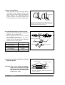
2. Remove burrs.
• Remove burrs from cut edges of pipes.
• Turn the pipe end toward down to avoid the
metal powder entering the pipe.
Caution:
If burrs are not removed, they may cause a gas
leakage.
3. Flaring the pipes.
• Insert the flare nuts, mounted on the
connection ports of both indoor and outdoor
unit, onto the copper pipes. Some gas may
leak, when the flare nuts are removed from
the indoor unit, as some gas is charged to
prevent the inside of the pipe from rusting.
• Fit the copper pipe end into the Bar of flare
tool about 0.5~1.0mm higher. (See
illustration)
• Flare the pipe ends.
4. Tape the flaring portion to protect it from
the dust or damages.
"A"
When properly flared, the internal surface of the
flare will evenly shine and be of even thickness.
After the flare part comes into contact with the
connectors, carefully check the flare finish.
Pipe cutter
Slanted
Rough
Pipe
Point down
Reamer
Handle
"A"; ø15.88 mm (5/8") ¡ 0~1.0 mm
ø12.7 mm (1/2") ¡ 0~0.5 mm
ø9.52 mm (3/8") ¡ 0~0.5 mm
ø6.35 mm (1/4") ¡ 0~0.5 mm
Cone
Red arrow mark
Clamp handle
Yoke
Bar
Bar
Copper pipe
= Improper flaring =
Inclined
Surface
damaged
Cracked
Uneven
thickness

ENGLISH 7
ENGLISH
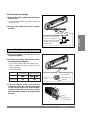
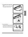
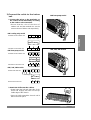
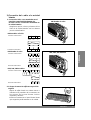
2) Connection of Pipings
1. Remove the indoor tubing with Drain hose
from the hole
• Remove tubing holder and pull the tubing out
of the chassis.
2. Replace the tubing holder into original
position.
For right rear piping
3. Route the tubing and the drain hose
straight backwards.
4. Insert the connecting cable into the indoor
unit through the piping hole.
• Do not connect the cable to the indoor unit.
• Make a small loop with the cable for easy
connection later.
• Connecting cable
5. Tape the tubing, drain hose and the
connecting cable. Be sure that drain hose
locates at the lowest side of the bundle.
Locating at the upper side can be a reason
that drain water overflows drain pan inside
the unit.
¤ŁPull
¤ Press
To remove the holder,
press the bottom of
chassis near the holder
upward and pull the tab
out of its hole.
Tubing holder
Connecting
cable
Gas side piping
Liquid side piping
Drain hose
Taping
Indoor/Outdoor
Connecting cable
18K
Cooling Model
Heat Pump Model
24K, 26K, 28K

8 ENGLISH
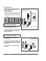
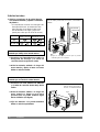
6. Indoor unit installation
• Hook the indoor unit onto the upper portion
of installation plate. (Engage the two hooks
of the rear top of the indoor unit with the
upper edge of the installation plate.)
Ensure the hooks are properly seated on the
installation plate by moving it left and right.
7. Connecting the pipings to the indoor unit.
• Align the center of the pipings and sufficiently
tighten the flare nut with fingers.
• Finally, tighten the flare nut with torque
wrench until the wrench clicks.
When tightening the flare nut with torque
wrench, ensure the direction for tightening
follows the arrow on the wrench.
8. Wrap the insulation material around the
connecting portion.
CAUTION: Take care to arrange the pipings,
drain hose and cables as the
picture on page 7 for inserting it
into the indoor unit and refixing
the tubing holder easily.
Connecting
cable
Drain hose
Press the lower left and right side of the unit
against the Installation Plate until the hooks
engage with their slots (sound click).
Flare nut
Pipings
Torque wrench
Spanner
Indoor unit tubing
Plastic Bands
Insulation material
Wrap the insulation material around the
connecting portion.
Pipe Size Torque
Liquid Side(1/4") 1.8kg
.
m
Liquid Side(3/8") 4.2kg
.
m
Gas Side(1/2") 5.5kg
.
m
Gas Side(5/8") 6.6kg
.
m

ENGLISH 9
ENGLISH
For the left pipings
3. Route the indoor tubing with the drain hose
to the piping hole as desired position.
4. Insert the pipings, power supply cord and
connecting cable into the piping hole.
5. Insert the connecting cable into the indoor
unit.
• Don't connect the cable to the indoor unit.
• Make a small loop with the cable for easy
connection later.
6. Tape the tubing, drain hose and the
connecting cable.
• Connecting cable
IndoorOutdoor
Drain pipe
Connecting cable
Connecting piping
¤ŁPull
To remove the holder,
press the bottom of
chassis near the holder
upward and pull the tab
out of its hole.
Tubing holder
¤ Press
Indoor/outdoor
connecting cable
Connecting
cable
Taping
Gas side piping
Liquid side piping
Drain hose
18K
Cooling Model
Heat Pump Model
24K, 26K, 28K

10 ENGLISH
7. Indoor unit installation
• Hook the indoor unit onto the upper portion
of installation plate. (Engage the two hooks
of the rear top of the indoor unit with the
upper edge of the installation plate.)
Ensure the hooks are properly seated on the
installation plate by moving it in left and right.
8. Connecting the pipings to the indoor unit.
• Align the center of the pipings and sufficiently
tighten the flare nut with fingers.
• Finally, tighten the flare nut with torque
wrench until the wrench clicks.
When tightening the flare nut with torque
wrench, ensure the direction for tightening
follows the arrow on the wrench.
Flare nut
Pipings
Torque wrench
Spanner
Indoor unit tubing
Plastic Bands
Insulation material
Wrap the insulation material around the
connecting portion.
9. Wrap the insulation material around the
connecting portion.
CAUTION: Take care to arrange the pipings,
drain hose and cables as the right
upper picture for inserting it into
the indoor unit and refixing the
tubing holder easily.
Connecting
cable
Drain hose
Press the lower left and right side of the unit
against the Installation Plate until the hooks
engage with their slots(sound click).
Pipe Size Torque
Liquid Side(1/4") 1.8kg
.
m
Liquid Side(3/8") 4.2kg
.
m
Gas Side(1/2") 5.5kg
.
m
Gas Side(5/8") 6.6kg
.
m

ENGLISH 11
ENGLISH
10. Set the pipings and the connecting cable
to the back of the chassis with the tubing
holder
• Hook the edge of tubing holder to tap on
chassis and push the bottom of tubing holder
to be engaged in the bottom of chassis.
11. Indoor unit installation
• Hook the indoor unit onto the upper portion
of installation plate. (Engage the two hooks
of the rear top of the indoor unit with the
upper edge of the installation plate.)
Ensure the hooks are properly seated on the
installation plate by moving it in left and right.
Piping
Taping
Drain hose
Tubing holder
¤ Hook
¤ŁPush
Connecting
cable
Drain hose
Press the lower left and right side of the unit
against the Installation Plate until the lower hooks
engage with their slots (sound click).

12 ENGLISH
4. Connecting Pipings and the cable to Outdoor unit
1) Connecting the pipings to the
Outdoor unit
1. Align the center of the pipings and
sufficiently tighten the flare nut with
fingers.
2. Finally, tighten the flare nut with torque
wrench until the wrench clicks.
• When tightening the flare nut with torque
wrench, ensure the direction for tightening
follows the arrow on the wrench.
Outdoor unit
Gas side piping
(Bigger Dia.)
Liquid side piping
(Smaller Dia.)
Torque wrench
CAUTION
After the confirmation of the above conditions, prepare the wiring as follows:
1) Never fail to have an individual power specialized for the air conditioner. As for the method
of wiring, be guided by the circuit diagram pasted on the inside of control box cover.
2) Provide a circuit breaker switch between power source and the unit.
3) The screw which fasten the wiring in the casing of electrical fittings are liable to come
loose from vibrations to which the unit is subjected during the course of transportation.
Check them and make sure that they are all tightly fastened. (If they are loose, it could
give rise to burn-out of the wires.)
4) Specification of power source.
5) Confirm that electrical capacity is sufficient.
6) See to that the starting voltage is maintained at more than 90 percent of the rated voltage
marked on the name plate.
7) Confirm that the cable thickness is as specified in the power sources specification.
(Particularly note the relation between cable length and thickness.)
8) Never fail to equip a leakage breaker where it is wet or moist.
9) The following troubles would be caused by voltage drop-down.
• Vibration of a magnetic switch, damage on the contact point there of, fuse breaking,
disturbance to the normal function of a overload protection device.
• Proper starting power is not given to the compressor.
Pipe Size Torque
Liquid Side(1/4") 1.8kg
.
m
Liquid Side(3/8") 4.2kg
.
m
Gas Side(1/2") 5.5kg
.
m
Gas Side(5/8") 6.6kg
.
m

1(L)
1(L)
1(L)
2(N)
2(N)
2(N)
3
3
3
4
5
1(L)
2(N)
3
4
5
1(L)
2(N)
ENGLISH 13
ENGLISH
2)
Connection of the cable
1. Remove the cover control from the unit by
loosening the screw.
Connect the wires to the terminals on the
control board individually as the following.
Outdoor unit
Terminal block
Connecting
cable
Power cord
(power connecting cable)
Cover control
Over 5mm
Power supply
2. Secure the cable onto the control board with the
holder (clamper).
3. Refix the cover control to the original position with
the screw.
4. Use a recongnized circuit breaker 20A(18K, 24K,
26K), 25A(28K) between the power source and the
unit. A disconnection device to adequately
disconnect all supply lines must be fitted.
Terminals on the outdoor unit
Terminals on the outdoor unit
Terminals on the outdoor unit
• 18K cooling only model
• 18K heat pump model
• 24K, 26K, 28K models
BROWN BLUE GN/YL BROWN
BROWN BLUE GN/YL BROWN
RED BLACK WHITE
RED BLACK WHITE
Terminals on the indoor unit
Terminals on the indoor unit
Terminals on the indoor unit
CAUTION
Ø10.0mm
(18K : Ø8.0mm)
Ø7.0mm
(18K : Ø5.0mm)
Ø8.0mm
The power cord connected to the
indoor unit should be complied with the
following specifications
(Type H05VV-F(Indoor), H07RN-F(Outdoor)
approved by HAR or SAA).
The connecting cable connected to
the indoor and outdoor unit should be
complied with the following
specifications
(Type H07RN-F approved by HAR or SAA).
The power connecting cable
(18K)connected to the indoor and
outdoor unit should be complied with
the following specifications
(Type H07RN-F approved by HAR or SAA).
NORMAL
CROSS-SECTIONAL
AREA 0.75mm
2
NORMAL
CROSS-SECTIONAL
AREA 2.5mm
2
(18K : 1.5mm
2
)
NORMAL
CROSS-SECTIONAL
AREA 1.5mm
2
BROWN BLUE GN/YL
BROWN BLUE GN/YL

14 ENGLISH
1) Checking the Drainage
1. Remove the Grille from the cabinet.
• Set the up-and-down air direction louver to
open position (horizontally) by finger
pressure.
• Remove 4 screws.
• To remove the Grille, pull lower the left and
right side of the grille toward you (slightly
tilted) and lift it straight upward (Four tabs on
the top inside edge of chassis are clear of
their slots).
2. Check the drainage.
• Pour a glass of water on the evaporator.
• Ensure if water flows drain hose of indoor
unit without any leakage.
5. Checking the Drainage and Connecting the cable to
Indoor unit
Grille
Chassis
Screw(3places)

ENGLISH 15
ENGLISH
2) Connect the cable to the indoor
unit
1. Connect the wires to the terminals on
the control board individually according
to the outdoor unit connection.
• Ensure that the color of the wires of
outdoor unit and the terminal No. are the
same as those of indoor unit respectively.
18K heat pump model
2. Attach the Grille onto the cabinet.
• Grasp lower the left and right side of the
Grille and engage four tabs on the top
inside edge of the chassis.
• Press the Grille toward the chassis until it
will be back into place.
24K, 26K, 28K models
1(L)
1(L)
1(L)
2(N)
2(N)
2(N)
3
3
3
4
5
1(L)
2(N)
3
4
5
1(L)
2(N)
Power supply
Terminals on the outdoor unit
Terminals on the outdoor unit
Terminals on the outdoor unit
• 18K cooling only model
• 18K heat pump model
• 24K, 26K, 28K models
BROWN BLUE GN/YL BROWN
BROWN BLUE GN/YL BROWN
RED BLACK WHITE
RED BLACK WHITE
Terminals on the indoor unit
Terminals on the indoor unit
Terminals on the indoor unit
BROWN BLUE GN/YL
BROWN BLUE GN/YL

16 ENGLISH
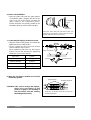
3) Form the pipings
1. Wrap the connecting portion of indoor unit
with the Insulation material and secure it
with two Plastic Bands.
(for the right pipings)
• If you want to connect an additional drain
hose, the end of the drain-outlet should keep
distance from the ground.(Do not dip it into
water, and fix it on the wall to avoid swinging
in the wind.)
• Connecting cable
2. Tape the Pipings, drain hose and
Connecting Cable from down to up.
3. Form the pipings gathered by taping along
the exterior wall and fix it onto the wall by
saddle or equivalent.
2. Tape the Pipings and Connecting cable
from down to up.
3. Form the pipings gathered by taping along
the exterior wall, make the Trap to be
required to prevent water from entering
into the room.
4. Fix the pipings onto the wall by saddle or
equivalent.
In case of the Outdoor unit being installed
below position of the Indoor unit.
In case of the Outdoor unit being installed
above position of the Indoor unit.
Seal a small opening
around the pipings with
gum type sealer.
Taping
Pipings
Connecting cable
Power supply cord
Plastic
band
• Trap is required to prevent water from entering
into electrical parts.
Seal a small opening
around the pipings
with gum type sealer.
Trap
Drain hose
18K
Cooling Model
Heat Pump Model
24K, 26K, 28K

ENGLISH 17
ENGLISH
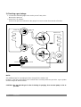
5. To open 2-way valve again, turn the
valve stem counter-clockwise until it
stops.
• Re-tighten the connecting portion with torque
wrenches.
No leakage found
Ieakage found
Outdoor unit
Cover control
Gas side
To indoor unit
Liquid side
Cap
Hexagonal
wrench
Service port cap
3-way valve
(Close)
2-way valve
(Open)
leakage ceased
leakage persists
Repair
leakage ceased
6. To purge the air, push the pin on the service
port of 3-way valve for three seconds with a
hexagonal wrench and set it free for one
minute. Repeat this three times.
Result
7. Set the both liquid and gas side valves to
open position with the Hexagonal wrench
for the unit operation.
6. Air Purging
1) Air purging
The air which contains moisture remaining in the
refrigeration cycle may cause a malfunction on
the compressor.
1. Remove the caps from the 2-way and 3-way
valves.
2. Remove the service-port cap from the
3-way valve.
3. Turn the valve stem of liquid side valve
counter-clockwise approx. 90¡˘and hold it
there for ten seconds, then close it.
4. Check a gas-leakage of the connecting
portion of the pipings.
CAUTION: Do not leak the gas in the air
during air purging. Use vacuum
pump as far as possible.

18 ENGLISH
2) Checking a gas leakage
1. Connect the manifold gauge to the service port of 3-way valve.
Measure the pressure.
2. Keep it for 5-10 minutes.
Ensure if the pressure indicated on the gauge is as same as that of measured at first time.
NOTE:
The additional gas for air purping has been charged in the outdoor unit.
However, if the flare connections have not been done correctly and there gas leaks, a gas cylinder
and the charge set will be needed.
CAUTION : Do not leak the gas in the air during air purging. Use vacuum pump as far as
possible.
Indoor unit
Liquid side
Closed
Outdoor unit
Gas side
Closed
CLOSE
CLOSE

ENGLISH 19
ENGLISH
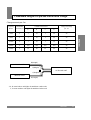
7. Maximum Length of Pipe and Freon Extra Charge
INDOOR UNIT
OUTDOOR UNIT
INDOOR UNIT
B(Length)
D(Length)
** A, B mean indoor unit higher located than outdoor unit.
C, D mean outdoor unit higher located than indoor unit.
A(Height)
C(Height)
Charge amount per 1m
Capacity STANDARD
CONNECTION TYPE
Charge amount(g)
(Btu/h) LENGTH(m)
A B C D
per 1m
~7000 4 7 15 7 15 20
~9000 4 7 15 7 15 20
~12000 4 7 15 7 15 20
~18000 5 40
~24000 5 15 30 15 30 40
15
(10)
15
(10)
30
(20)
30
(20)

20 ENGLISH
Discharge air
(Cooling)
2) Evaluation of the performance
1. Measure the temperature of the intake and
discharge air.
2. Ensure the difference between the intake
temperature and the discharge one is more
than 8¡˘C (Cooling) or reversely (Heating).
8. Test running
RESET
RESET
RESET
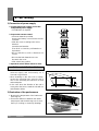
Settlement of Outdoor Unit
• Anchor the outdoor unit with a bolt and nut
(ø10cm) tightly and horizontally on a
concrete or rigid mount.
• When installing on the wall, roof or rooftop,
anchor the mounting base securely with a
nail or wire assuming the influence of wind
and earthquake.
• In the case when the vibration of the unit is
conveyed to the house, settle the unit with an
anti-vibration rubber.
Bolt
Tubing connection
1) Connection of power supply
1. Connect the power supply cord to the
independent power supply.
• Circuitbreaker is required.
2. Prepare the remote control.
• Insert two batteries provided.
Remove the battery cover from the remote
controller.
• Slide the cover according to the arrow
direction.
Insert the two batteries.
(Two "R03" or "AAA" dry-cell batteries or
equivalent.)
• Be sure that the (+) and (-) directions are
correct.
• Be sure that both batteries are new.
Re-attach the cover.
• Slide it back into position.
3. Operate the unit for fifteen minutes or more.

ESPAÑOL 21
ESPAÑOL
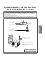
ACONDICIONADORES DE AIRE TIPO SPLIT
INSTRUCCIONES DE INSTALACION
• Por favor, lea atentamente estas instrucciones antes de instalar el equipo.
• Este Aire Acondcionado debe ser instalado por solamente persona autorizada
según la Norma.
• Nacional de la instalción eléctrica.
Cambio de cable elétrico ser realizado por persona autorizada solamente.
1. Tomillo tipo "A"
3. Tomillo tipo "B"
4. Soporte del telemando
2. Panel de Instalación
Más de 5cm
5. Tuber
ía de cobre (Liquido)
6. Tuber
ía de cobre (Gas)
7. Cable red(cable de alimentación)
8. Cable de conexión
(a exepcion del modelo solo frio 18K)
Más de
10cm
Más de
10cm
Más de
70 cm
Le mod
ŁŁll
e "Froid et
chauffage" est
ØØqq
uipÈ d'un
Los modelos de bomba de calor
incluyen accesorio de drenaje.
1cm
Más de
5cm

22 ESPAÑOL
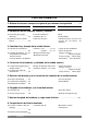
Perfil de Instalación
Trabajo de instalación
Accesorios para la instalación
Herramienta requerida
2. Instalación de las unidades interior y exterior
1. Debera observarse siempre lo siguiente por razones de seguridad
.............
23
1) Selección de la mejor
ubicación
...........................
24
2) Instalación de la unidad
interior
...............................
25
• Panel de instalación
• 4 tomillos tipo "A"
• Cable de conexión
• Nivel
• Destomillador
• Taladro eléctrico con broca de
corona de 60-70mm. de
diámetro.
3. Canalización y drenaje de la unidad interior
1) Preparación de tuberías
.........................................
26
2) Conexión de tuberías
..
27~31
• Para tuberías en la parte
derecha trasera
• Para las tuberias a la izquierda
• Tuberías: Gas
.............
1
/2",
5
/8"
Líquido
.......
1
/4",
3
/8"
• Manguera de drenage
• Materiales aislantes
• Juego de abocardadores
• Llaves de presión
1.8 kg
.
m, 4.2 kg
.
m
........................
.........................
Tubería de líquido
5.5 kg
.
m, 6.6 kg
.
m
.....
Tubería de gas
Llave inglesa
......
Unión de tuberías
4. Conexión de las tuberías y cableado de la unidad exterior
1) Conexión de tuberías de la
unidad exterior
..................
32
2) Conexión del cable de
alimentación
.....................
33
• Manga de drenage adiccional
(Diámetro exterior ...15.5 mm)
•
Llaves de presión
1
.8 kg
.
m, 4.2 kg
.
m
.........................
.........................
Tubería de líquido
5.5 kg
.
m, 6.6 kg
.
m
......
Tubería de gas
5. Revisión del drenaje y de la conexión del cableado de la unidad exterior
1) Revisión del drenaje
........
34
2) Conexión del cableado
.....
35
3) Aislamiento de las tuberías
.......
36
•
Un vaso de agua
•
Destomillador
6. Purgado de las tuberías y de la unidad interior
1) Purga del aire
..................
37
2)
Verificación fugas de gas
.......
38
• Llave fija (4mm)
• Detector de fugas de gas
8. Comprobación del funcionamiento
7. Maxima longitud de la tuberia y carga extra de fréon
...........................................
39
1) Enchufe el aprato a lad red
eléctrica
.........................................
40
2) Evaluación del funcionamiento
.........................................
40
• 2 tomillos tipo "B" • Manual de usuario
• Termómetro

ESPAÑOL 23
ESPAÑOL
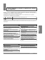
1. Debra observarse siempre lo siguiente por razones
de seguridad
• Informe o solicite el consentimiento de las autoridades de suministro antes de la conexióne al sistema.
• Asegúrese de leer "DEBERA OBSERVARSE SIEMPRE LO SIGUIENTE POR RAZONES DE
SEGUIRDAD" antes de instalar el acondicionador de aire.
• Asegúrese de tomar las precauciones siguientes porque son muy importantes para la seguridad.
• Las indicaciones y significados son los siguientes.
• Después de leer este manual, déselo al cliente con el manual de instrucciones para que lo guarde en un
lugar seguro.
Podría causar la muerte, lesiones graves, etc.
El cliente no debe instalar el acondicionador de aire.
Realice firmemente la instalación consultando el
manual de instrucciones.
Instale firmemente la unidad en un lugar que pueda
soportar su peso.
Realice el trabajo eléctrico siguiendo las instrucciones
del manual de instalación, y asegurándose de emplear
un circuito exclusivo.
Instale firmemente las cubiertas de las partes eléctricas de
la unidad interior y el panel de servicio de la unidad exterior.
Asegúrese de utilizar las piezas suministradas o las piezas
especificadas para realizar el trabajo de instalación.
Compruebe que el gas refrigerante no escape después
de finalizar el trabajo de instalación.
Haga la conexión a tierra.
No instale la unidad en un lugar donde haya fugas de
gas inflamable.
Realice con seguridad el trabajo de drenaje/instalación de
tuberías según las indicaciones del manual de instrucciones.
Utilice los cables especificados para conectar
firmemente las unidades interior y exterior, y coloque
bien los cables en las secciones de conexión del cuadro
de terminales para que el esfuerzo de los cables no se
aplique a las secciones de conexión.
• Una instalación incompleta podría causar lesiones debido a incendios,
sacudidas eléctricas, caídas de la unidad o escapes de agua. Para
hacer la instalación, consulte con el concesionario a quien adquirió esta
unidad o con un instalador especial.
• Una instalación incompleta podría causar lesiones personales
debido al fuego, sacudidas eléctricas, caídas de la unidad o
escapes de agua.
• Cuando instale la unidad en un lugar que no sea lo
suficientemente fuerte, ésta podría caerse y causar lesiones.
• Las conexiones u las fijaciones mal hechas podrían causar incendios.
• Si la capacidad del circuito de alimentación no es suficiente o el
trabajo eléctrico no está completo, podría producirse un incendio o
una sacudida eléctrica.
• El empleo de piezas defectuosas podría causar lesiones o escapes
de agua debido a un incendio, sacudidas eléctricas, caídas de la
unidad, etc.
• Si hay fugas de gas y éste se acumula en el área que rodea a la
unidad, podria producirse una explosión.
• Si el trabajo de drenaje/instalación de tuberías tiene defectos, el agua
podría escapar de la unidad y mojar o estropear los enseres del hogar.
• No conecte le cable de tierra a una tubería de gas, tuberia de agua,
pararrayos o cable de tierra de un teléfono. Una mala conexión a tierra
podría causar una sacudida eléctrica.
• Si no se colocan firmemente la cubierta de las partes eléctricas de la unidad
interior y/o el panel de servicio de la unidad exterior, podría producirse un
incendio o una sacudida eléctrica debido al polvo, al agua, etc.
Podría causar lesiones graves, en lugares particulares si no se opera correctamente.
ADVERTENCIA
ADVERTENCIA
CUIDADO
CUIDADO

24 ESPAÑOL
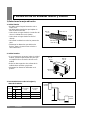
2. Instalación de las unidades interior y exterior
A
B
1) Seleccionar la mejor ubicación
1. Unidad interior
2. Unidad exterior
3. Recomendaciones sobre la longitud y
altura de la tubería.
• No debe existir ninguna fuente de calor o
vapor cerca.
• No debe haber obstáculos que impidan la
libre circulación del aire.
• Seleccionar un lugar donde la circulación del
aire en la habitación sea la óptima.
• Seleccionar un lugar donde sea fácil el
drenaje.
• No instale la unidad cerca de las puertas de
paso.
• Mantenga las distancias que indican las
flechas, tanto a la pared como al techo u
otros obstáculos.
• Si se construyera un parasol sobre la unidad
exterior, prestar especial atención para que
no impida la libre circulación del aire en la
unidad.
• Evitar las descargas de aire caliente de la
unidad sobre animales y/o plantas.
• Mantenga las distancias indicadas en el
gráfico.
Más de
5 cm
Más de 5 cm
Más de
5 cm
Más alto del
nivel del ojo
Más de
10 cm
Más de
10 cm
Más de
70 cm
Unidad
interior
Unidad
exterior
Tamaño de la
tubería
GAS LIQUIDO
Longitud máxima
en metros
A (m)
Altura máxima
en metros
B (m)
1/2" 1/4" 30 15
5/8" 1/4" 30 15
5/8" 3/8" 30 15
18K
Modelos
24K, 26K
28K

ESPAÑOL 25
ESPAÑOL
A,B
A,B,C
C
D
D
5-7mm
A,B,D
C
A
B,D
C
ø70mm
2) Instalación de la unidad interior
La pared debe ser lo suficientemente solida para
evitar vibraciones.
1. Asegure a la pared la placa de sujección
con 4 tornillos tipo "A".
• Utilice un nivel para asegurar la correcta
posición horizontal.
2. Taladrar la pared o el muro con una broca
de 70mm de diámetro.
• Las flechas de la parte inferior, tanto
izquierda como derecha, de la placa de
sujección indican el punto donde efectuar el
taladro.
• Tenga en cuenta que el efetuar el taladro,
ésta debe éstar inclinado hacia el exterior.
Tornillo tipo "A"
Panel de instalación
Línea de marca OFF
Cuerd
Peso
Parte inferior, izquierda y derecha de la
place de sujección.
Tubería de derecha
atrás
Tubería de izquierda
atrás
Interior
Exterior
Pared
Centro
Panel de instalaci
ó
n

26 ESPAÑOL
"A"
Tubería de cobre
Maneta
Marco de flecha roja
3. Canalización y drenaje de la unidad interior
1) Preparación de tuberías
1. El corte de tuberías y el cable eléctrico.
• Use las herramientas idóneas para trabajar
las tuberías de cobre.
• Mida la distancia entre las unidades interior y
exterior.
• Corte las tuberías un poco más largas que la
medida obtenida.
2. Limpiar la rebaba
• Limpie las rebabas producidas por el corte.
• Poner la tubería boca-abajo, para evitar la
entrada del polvo de metal en su interior.
Cuidado:
Si la tubería no está completamente limpia en
su interior, provocará una guga de gas.
3. Abocardar tuberías
• Introducir las tuercas de abocardar en las
conexiones, tanto de la unidad interior como
de la exterior, dentro de los tubos de cobre.
Puede gugarse algo de gas cuando las
tuercas se quitan de la unidad interior,
debiéndose cargar la parte equivalente que
se halla perdido, para evitar su
enmohecimiento.
• Introduzca la tubería de cobre en el
abocardador unos 0.5~1.0mm (Vea la
ilustración)
• Abocarde la tubería.
4. Abocarde lo preciso para protegerlo del
polvo y otros daños.
En un abocardado perfacto, la superficie interna
estará brillante y con un grosor uniforme.
Revise el abocardado una vez terminado.
Cortador de tubería
Inclinado
Aspero
Tubería
Punta hacia
abajo
Instrumento de pulido
Bar
Bar
Cone
Agarrador
"A"; ø15.88 mm (5/8") ¡ 0~1.0 mm
ø12.7 mm (1/2") ¡ 0~0.5 mm
ø9.52 mm (3/8") ¡ 0~0.5 mm
ø6.35 mm (1/4") ¡ 0~0.5 mm
Yunque
= Abocardados incorrectos =
Indlinado
Superficie
dañada
Roto
Desigual
espesor

ESPAÑOL 27
ESPAÑOL
2) Conexión de tuberías
1. Retire los tubos de la parte posterior de la
unidad, quitando el soporte que los
asegura a la misma.
• Remove tubing holder and pull the tubing out of
the chassis.
2. Reemplace el soporte de los tubos a
suposición original.
Para tuberías en la parte derecha trasera
3. Tire de los tubos hacia atrás.
4. Introduzca el cable de conexión de la
unidad inferior por el agiijero practicado en
la misma.
• No conecte el cable a la unidad interior.
• Haga un pequeño nudo en el cable para
posteriormente facilitar la conexión.
5. Fije con cinta adhesiva los tubos, la
manguera de drenaje y el cable de
conexión.
Tubo de liquido
Tubo de gas
Cable de
conexión
Manguera de drenaje
Soporte de los tubos
Para quitar el soporte
que asegura los tubos al
chasis de la unidad,
presion hacia arriba y
retire el soporte.
¤ Presionar
¤ŁTirar
Cinta adhesiva
Cable de conexi
ó
n unidades
interior y exterior
18K
Modelos sólo frio Bomba de calor
24K, 26K, 28K

28 ESPAÑOL
6. Instalación de la unidad interior
• Enganche la unidad interior por la parte
superior de la placa de sujección,
previamente fijada a la pared.
Asegúrese que está debidamente sujeta,
moviendo levemente la unidad de izquierda
a derecha.
7. Conexión de las tuberías a la unidad
interior.
• Alinear las tuberias y apretar con los dedos
las tuercas.
• Finalmente, apriee firmemente la tuerca con
la llave de presión hasta que ceda y suene
un "click", según la dirección de la flecha
impresa en la llave.
Tubería unidad interior
Bridas de plástico
Material aishante
Aisle las coneexiones
Llave fija
Llave de presión
Tuerca Tuberías
Presionar con ambas manos la parte inferior
derechae izquierda contra la placa de sujección
hasta oir un "click".
8.Rodee con material aislante las conexiones.
Cable de
conexi
ó
n
Manguera
de desagüe
Tamaño del tubo Presión
Liquido (1/4") 1.8kg
.
m
Liquido (3/8") 4.2kg
.
m
Gas (1/2") 5.5kg
.
m
Gas (5/8") 6.6kg
.
m

ESPAÑOL 29
ESPAÑOL
Para las tuberías a la izquierda
3. Retire el soporte de sujección de los tubos
y tire de ellos hacia fuera del chasis de la
unidad.
4. Introduzca los tubos y el cable de conexión
de la unidad interior por el agüjero
practicado en la pared.
5. Introduzca el cable de la unidad interior
• No conecte el cable a la unidad interior.
• Haga un pequeño nudo en el cable para
posteriormente facilitar la conexión.
6. Ate con cinta adheseve los tubos, la
manguera de drenaje y el cable de
conexión.
Extrior
Cable de
conexión
Cinta adhesiva
Tubo de gas
Tubo de liquido
Manguera de drenaje
Interior
Cable de conexi
ó
n
Cable de conexión
de las unidades
interior y exterior
Soporte de los tubos
Para quitar el soporte que
asegura los tubos al
chasis de la unidad,
presion hacia a rriba y
retire el soporte.
¤ Presionar
¤ŁTirar
18K
Modelos sólo frio
Bomba de calor
24K, 26K, 28K
Tuberías
Manga de drenage adiccional

30 ESPAÑOL
7. Instalación de la unidad interior
• Enganche la unidad interior por la parte
superior de la placa de sujección, previamente
fijada a la pared.
Asegúrese que está debidamente
sujeta,moviendo levemente la unidad de
izquierda a derecha.
8. Conexión de las tuberías a la unidad
interior
• Alinear kas tuberías y apretar con los dedos
las tuercas.
• Finalmente, apriee firmemente la tuerca con
la llave de presión hasta que ceda y suene
un "click", según la dirección de la flecha
impresa en la llave.
9. Rodee con material aislante las
conexiones
Tuberia unidad interior
Llave fija
Llave de presion
Tuerca Tuberias
Presionar con ambas manos la parte inferior
derechae izquierda contra la placa de sujección
hasta oir un "click".
Cable de
conexi
ó
n
Manguera
de desagüe
Bridas de plástico
Material aishante
Aisle las conexiónes
Tamaño del tubo Presión
Liquido (1/4") 1.8kg
.
m
Liquido (3/8") 4.2kg
.
m
Gas (1/2") 5.5kg
.
m
Gas (5/8") 6.6kg
.
m

ESPAÑOL 31
ESPAÑOL
10. Asegure las tuberías y el cable de conexión
a la parte trasera del chasis con el soporte
de sujección de las tuberías.
11. Instalación de la unidad interior
• Enganche la unidad interior por la parte
superior de la placa de sujección,
previamente fijada a la pared.
Asegúrese que eatá debidamante sujeta
moviendo levemente la unidad de izquierda
a derecha.
Presionar con ambas manos la parte inferior
derechae izquierda contra la placa de sujección
hasta oir un "click".
Cable de
conexión
Tuberia
Cinta
adhesiva
¤ Presilla
¤ŁPresione
Manguera
de desagüe
Manguera
de desagüe

32 ESPAÑOL
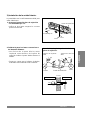
4. Conexión de tubos y cable de alimentación a la unidad exterior
1) Conexión de tuberías de la unidad
exterior
1. Alinee las tuberías y apriete con los dedos
las tuercas.
2. Finalmente apriete firmemente la tuerca
con la llave de presión hasta que ceda y
suene un "click", según la dirección de la
flecha impresa en la llave.
Unidad exterior
Tubo de gas
Tubo de liquido
Llave de presión
CUIDADO
INSTALACION DE HILOS Y CABLES ELECTRICOS
1) Es imprescindible que la instalación tanto electrica como la canalización la realice un instalador
especializado en aire acondicionado. Para el procedimiento de cableado(conexionado) debera
seguirse el diagrama de circuito impreso en el interior de la cubierta de la caja de control.
2) Instalar un interruptor de corte de corriente entre la torna de fuerza y la unidad.
3) Los tornillos que sujetan los cables en la caja de accesorios electricos, son susceptibles de
perdida, a causa de las vibraciones a que la unidad esta expuesta durante el periodo de
transporte. Revisar y asegurarse que estan fuertermente sujetas(si se han perdido, daria origen
a sobrecaleniamiento y prendimiento de los cables).
4) Especificación de la fuente de fuerza(torna de fuerza).
5) Confirmar que la capacidad electrica es la suficiente.
6) Comprobar que el voltaje de arranque se mantiene a más del 90% del voltaje indicado en la
placa de caracteristicas.
7) Confirmar que el grosor del cable es el indicado en las especificaciones de torna de
fuerza.(Particularmente compruebe la relación entre longitud y grsor.)
8) No dude en aplicar un corta fugas donde este mojado u observe humedad.
Compruebe posteriormente con un busca fugas que no existe ninguna.
9) Una fuerte caida de voltaje provocari los siguientes desajustes:
• Vibración de un interruptor magnetico, daños en los puntos de contacto, rotura de fusibles,
desajustes en el normal funcionamiento del disposibivo de protección de sobrecargas.
• No se transmitiria la fuerza necesaria al compresor para el arranque.
Tamaño del tubo Presión
Liquido (1/4") 1.8kg
.
m
Liquido (3/8") 4.2kg
.
m
Gas (1/2") 5.5kg
.
m
Gas (5/8") 6.6kg
.
m

ESPAÑOL 33
ESPAÑOL
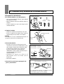
2)
Conexi
ó
n del cable de alimentaci
ó
n
1. Retire la cubierta del panel de control con un
destomillador.
Conecte los cables a los terminales del panel
de control individualmente.
Unidad exterior
Conextión terminal
Más de 5mm
Cubierta del
panel de control
Sujección para el
cable de conexión
Cable de alimentación
(Cable red)
CUIDADO
Ø10.0mm
(18K : Ø8.0mm)
Ø7.0mm
(18K : Ø5.0mm)
Ø8.0mm
El enchufe conectado sujección para el
cable de conexión a la unidad interior
debe aplicarse con 2.5mm
2
conductores.
(Tipo H05VV-F(Interior), H07RN-F(Exterior)
HAR o SAA Aprobacion)
El cable conexión conectado a las
lunidaes interior y exterior debe
aplicarse con 0.75mm
2
conductores.
(Tipo H07RN-F HAR o SAA Aprobacion)
El cable red(18K) conectado a las
lunidaes interior y exterior debe
aplicarse con 1.5mm
2
conductores.
(Tipo H07RN-F HAR o SAA Aprobacion)
DIAMETRO
NOMINALAREA
SECCIONAL 2.5mm
2
(18K : 1.5mm
2
)
DIAMETRO
NOMINALAREA
SECCIONAL 0.75mm
2
DIAMETRO
NOMINALAREA
SECCIONAL 1.5mm
2
2. Asegure el cable eléctrico al panel de control con
la presilla de sujección.
3.Coloque de nuevo la cubierta del panel de control
atonillándola.
4. Usar un limitador de consumo de 20A(18K, 24K,
26K), 25A(28K) entre la fuente de electricidad y
la unidad. Se debe instalar un mecanismo de
desconexion para desconectar adecuadamente
todas las lineas de suministro.
1(L)
1(L)
1(L)
2(N)
2(N)
2(N)
3
3
3
4
5
1(L)
2(N)
3
4
5
1(L)
2(N)
Cable de alimentación
Terminales unidad interior
Terminales unidad interior
Terminales unidad interior
• 18K modelos sólo frio
• 18K bomba de calor
• 24K, 26K, 28K modelos
MARRON
AZUL V/A
MARRON
AZUL V/A
MARRON AZUL V/A MARRON
MARRON AZUL V/A MARRON
RED NERGO BLANCO
RED NERGO BLANCO
Terminales unidad exterior
Terminales unidad exterior
Terminales unidad exterior

34 ESPAÑOL
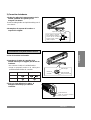
1) Revisión sel drenaje
1. Retire la rejilla frontal de la unidad
• Mueva con los dedos las lamas direccionales
del aire y colóquelas en posición horizontal.
• Quite los cubre tomillos y los tomillos en
ambos extremos del panel frontal.
• Para retirar la rejilla frontal tire de ella hacia
fuera y amba suavemente y quedará
levatada (dos pestañas en los bordes
superiores de la rejilla permiten que ésta se
mantenga abierta).
2. Comprobación del drenaje
• Vacíe un vaso de agua en el evaporador
• Asegúrese de que el agua fluye por la
manguera de drenaje hacia el exterior.
Grille
Chassis
Tornillo (ambos lados,
izquierdo y derecho)
5. Revisión del drenaje y conexión del cable a la unidad interior

ESPAÑOL 35
ESPAÑOL
2) Conexión del cable a la unidad
interior
1. Conecte los hilos a sus terminales en el
panel de control individualmente, de
acuerdo con las conexiones efectuadas en
la unidad exterior.
• Asegúrese que los colores y números de los
hilos de la unidad exterior son los mismos
para la unidad interior.
2. Coloque de nuevo la rejilla en su posición
original
• Agarre la rejilla frontal con ambas manos e
introduzca las pestañas de los extremos en
las ranuras de la parte frontae; inferior
izquierda y derecha.
• Presione suavemente el panel frontal hasta
que enganche perfectamente en la unidad.
18K bomba de calor
24K, 26K, 28K modelos
1(L)
1(L)
1(L)
2(N)
2(N)
2(N)
3
3
3
4
5
1(L)
2(N)
3
4
5
1(L)
2(N)
Cable de alimentación
Terminales unidad interior
Terminales unidad interior
Terminales unidad interior
• 18K modelos sólo frio
• 18K bomba de calor
• 24K, 26K, 28K modelos
MARRON
AZUL V/A
MARRON
AZUL V/A
MARRON AZUL V/A MARRON
MARRON AZUL V/A MARRON
RED NERGO BLANCO
RED NERGO BLANCO
Terminales unidad exterior
Terminales unidad exterior
Terminales unidad exterior

36 ESPAÑOL
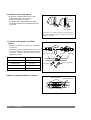
3) Asilar los tubos
1. Aisle las conexiones de la unidad interior
con material aislante y sujételo con bridas
de plástico.
• Si usted desea conectar una manguera de
desagüe adiccional, el extremo de éata
debe guardar cierta distancia del suelo.
(No la introduzca en agua, y fijela a la
pared para evitar que el viento la mueva)
2. Envuelva con cinta adhesiva os tubos, la
manguera de drenaje y el cable de
conexion desde avajo hacia arriba.
3. Aisle las tuberías unidad a lo largo del
muro exterior y fijelos al muro con unas
bridas o artículo similar.
2. Envuelva con cinta adhisiva las tuberías
y el cable de conexión desde abajo hacia
arriba.
3. Aisle las tuberías unidas a lo largo del
muro exterior y haga un codo para
prevenir que no pueda resbalar agua
hacia el interior (ver figura).
4. Fije las tuberías a la pared mediante
bridas o artículo equivalente.
En el caso de que la unidad exterior esté
instalada por debajo de la unidad interior
En el caso de que la unidad exterior esté
instalada por encima de la unidad interior
Selle el orificio practicado en el muro, con material
sellante.
• Haga un codo para prevenir que no pueda
resbalar agua hacia el interior.
Selle el orificio practicado en
el muro, con material sellante
Codo
Bandas de plástico
Cinta aislante
Manguera drenaje
Tuberías
Cable de conexión
Cable de
alimentación
18K
Modelos sólo frio Bomba de calor
24K, 26K, 28K

ESPAÑOL 37
ESPAÑOL
5. Para abrir otra vez la válvula de 2
vías, gire el vástago de la misma en
el sentido de las agujas del reloj
hasta hacer tope.
• Apriete de nuevo las tuercas de conexi
ó
n con
la llave de presi
ó
n
Si no se encuentra fuga
Si no encuentra fuga
Unidad exterior
Cubierta panel
de control
Tubería de gas
Tubería liquido
unidad interior
Llave
hexagonal
Tuercas
ciegas
Tuerca de servicio
Válvula de 3 vías
(cerrada)
Válvula de 2 vías
(abierta)
Case de la fuga
La fuga persiste
Localice y repare el escape
La fuga persiste
6. Para la purga del aire, oprima el obus de la
válvula de servicio de 3 vías durante tres
segundos, y posteriormente, con una llave
hexagonal manténgala abierta durante un
miunuto.
Resultado
7. Para el funcionamiento de la unidad, deje
abiertas las válvulas de 2 y 3 vías.
6. Purga del aire de las tuberías y de la unidad interior
1) Purga del aire
Si dentro del ciclo de refrigeración quedara aire
húmedo, podría dañar seriamente el compresor.
1. Retire los tapones de las válvulas de 2 y 3
vías.
2. Retire la tuerca de servicio de la válvula de
3 vías.
3. Para abrir la válvula de 2 vías, gire el
vastago en el sentido de las agujas del reloj
90° aprox. y manténgala así durante 10
segundos aprox. A continuación ciérrela.
4. Asegúrese que no haya fugas de gas en las
conexiones de las tuberías.

38 ESPAÑOL
2) Comprobación de fuga de gas en las tuberías
1. Conecte el puente de manómetros a la válvula de servicio de 3 vías.
Mida la presión.
2. Espere durante 5 ó 10 minutos .
Compruebe que la presión indicada es la misma que la obtenida en la medición anterior.
NOTA:
La unidad exterior lleva una carga adicional de gas para la purga del mismo.
Sin embargo, si el abocardado el las conexiones no se ha realizado correctamente, se necesitará
cargar la parte correspondiente de gas que se haya podido fugar.
Cuidado: No expulsar el gas a la atmósfera durante el procedimiento de purga.
Unidad interior
Tubo de liquido
Cerrado
Unidad exterior
Tubo de gas
Cerrado
CERRADO
CERRADO

ESPAÑOL 39
ESPAÑOL
7. Maximum Length of Pipe and Freon Extra Charge
** A, B media de la unidad interna localizada mas alta que la unidad externa.
C, D media de la unidad externa localizada mas alta que la unidad interna.
UNIDAD INTERIOR
UNIDAD EXTERIOR
UNIDAD INTERIOR
B(Longitud)
D(Longitud)
A(Altura)
C(Altura)
1) Cantidad de Carga for 1m
CAPACIDAD
LONGITUD
TIPO DE CONEXIÓN
CANT. CARGA
(Btu/h)
ESTANDAR(m)
A B C D
POR 1m
~7000 4 7 15 7 15 20
~9000 4 7 15 7 15 20
~12000 4 7 15 7 15 20
~18000 5 15 15 40
~24000 5 15 30 15 30 40
30
(20)
30
(20)

40 ESPAÑOL
Solo frío
2) Evaluación de funcionamiento
1. Mida la temperatura de impulsión y retorno
del aire.
2. Asegúrese que hay una diferencia mayor de
8° entre ambos (impulsión y retorno).
8. Comprobación de funcionamiento
RESET
RESET
RESET
Instalación de la unidad exterior
• Anclar la unidad exterior con tuercas,
tomillos y arandelas sobre una base sólida.
• Cuando se instale en muro o tejado, anclarla
fijamente igual, atándola además con flejes o
material similar a fin de prevenir fuertes
vientos o movimientos de tierra.
• Coloque antivibradores, si la unidad
transmite vibraciones a la vivienda.
Tuercas
Conexión de los tubos
1) Enchufe el aparato a la red eléctrica
1. Conecte el prarato a una fuente
independiente.
2. Prepare el telemando.
• Quite la tapa de las baterías de la parte
posterior del telemando y coloque las
baterías.
• Inserte las dos pilas del modelo "R03" o
"AAA"(alcalinas o equivalentes), siguiendo
la dirección que indican las flechas.
• Asegúrese de que la colocación de los
polos (+) y (-) es la correcta.
• Compruebe que las baterías son nuevas
(sin uso).
• Coloque de nuevo la tapa en su posición
original.
3. Haga funcionar la unidad en modo de frío
durante un mínimo de quince minutos.
-
 1
1
-
 2
2
-
 3
3
-
 4
4
-
 5
5
-
 6
6
-
 7
7
-
 8
8
-
 9
9
-
 10
10
-
 11
11
-
 12
12
-
 13
13
-
 14
14
-
 15
15
-
 16
16
-
 17
17
-
 18
18
-
 19
19
-
 20
20
-
 21
21
-
 22
22
-
 23
23
-
 24
24
-
 25
25
-
 26
26
-
 27
27
-
 28
28
-
 29
29
-
 30
30
-
 31
31
-
 32
32
-
 33
33
-
 34
34
-
 35
35
-
 36
36
-
 37
37
-
 38
38
-
 39
39
-
 40
40


LG LSUD1866HM Guía de instalación
- Tipo
- Guía de instalación
en otros idiomas
- English: LG LSUD1866HM Installation guide
Artículos relacionados
-
LG LS-D2422CL Guía de instalación
-
-
-
-
-
LG ARNU18GS5A1 Guía de instalación
-
LG A3UW36GFAB.AWGTLAR Manual de usuario
-
LG A3UW24GFAB El manual del propietario
-
-