Magic Chef MCSRE24S El manual del propietario
- Categoría
- Cocinas
- Tipo
- El manual del propietario

1
PLEASE READ THIS MANUAL CAREFULLY BEFORE USING YOUR
ELECTRIC RANGE AND KEEP IT FOR FUTURE REFERENCE.
Model MCSRE24S
24-Inch Freestanding
Electric Range
User’s Manual

2
PRODUCT REGISTRATION
Thank you for purchasing this Magic Chef® product. The first step to protect your new product is to complete the product
registration on our website: www.mcappliance.com/register. The benefits of registering your product include the following:
1. Registering your product will allow us to contact you regarding a safety notification or product update.
2. Registering your product will allow for more efficient warranty service processing when warranty service is required.
3. Registering your product could act as your proof of purchase in the event of insurance loss.
Once again, thank you for purchasing this Magic Chef product.

3
CONTENTS
PRODUCT REGISTRATION . . . . . . . . . . . . . . . . . . . . . . . . . . . . . . . . . . . . . . . . . . . . . . . . . . . . . 2
PRECAUTIONS . . . . . . . . . . . . . . . . . . . . . . . . . . . . . . . . . . . . . . . . . . . . . . . . . . . . . . . . . . . . . . . 4
IMPORTANT SAFETY INSTRUCTIONS . . . . . . . . . . . . . . . . . . . . . . . . . . . . . . . . . . . . . . . . . . . 5
SPECIFICATIONS. . . . . . . . . . . . . . . . . . . . . . . . . . . . . . . . . . . . . . . . . . . . . . . . . . . . . . . . . . . . . . 8
PARTS AND FEATURES . . . . . . . . . . . . . . . . . . . . . . . . . . . . . . . . . . . . . . . . . . . . . . . . . . . . . . . . 9
INSTALLATION REQUIREMENTS. . . . . . . . . . . . . . . . . . . . . . . . . . . . . . . . . . . . . . . . . . . . . . . .10
INSTALLATION INSTRUCTIONS . . . . . . . . . . . . . . . . . . . . . . . . . . . . . . . . . . . . . . . . . . . . . . . .12
BEFORE USE . . . . . . . . . . . . . . . . . . . . . . . . . . . . . . . . . . . . . . . . . . . . . . . . . . . . . . . . . . . . . . . . .16
OPERATION INSTRUCTIONS. . . . . . . . . . . . . . . . . . . . . . . . . . . . . . . . . . . . . . . . . . . . . . . . . . .17
CARE AND MAINTENANCE . . . . . . . . . . . . . . . . . . . . . . . . . . . . . . . . . . . . . . . . . . . . . . . . . . . 20
TROUBLESHOOTING. . . . . . . . . . . . . . . . . . . . . . . . . . . . . . . . . . . . . . . . . . . . . . . . . . . . . . . . . 22
LIMITED WARRANTY . . . . . . . . . . . . . . . . . . . . . . . . . . . . . . . . . . . . . . . . . . . . . . . . . . . . . . . . 23

4
PRECAUTIONS
EXPLANATION OF SYMBOLS
WARNING
Hazards or unsafe practices which COULD result in severe personal injury or death.
CAUTION
Hazards or unsafe practices which COULD result in minor personal injury.
THIS PRODUCT IS INTENDED FOR
HOUSEHOLD USE ONLY
WARNING: Read and understand all safety precautions. Failure to follow all instructions described in this user
manual may result in electric shock, fire and/or serious personal injury. The warnings, cautions and instructions
discussed in this user manual cannot cover all possible conditions and situations that may occur.
ELECTRIC POWER
If an electric circuit is overloaded with other appliances, the Electric Freestanding Range may not operate
properly. The Freestanding Electric Range should be operated on a separate electrical circuit from other operating
appliances.

5
IMPORTANT SAFETY INSTRUCTIONS
WARNING: To reduce the risk of fire, electric shock, or serious personal injury, please read and save all
instructions before using the Electric Freestanding Range.
When using this or any other electrical appliance, basic safety precautions should be observed, including the
following:
1. READ ALL INSTRUCTIONS BEFORE USE.
2. Have a qualified technician properly install and ground the appliance in accordance with the National
Fuel Gas Code ANSI Z223.1- latest edition in the United States, or in Canada CAN/CGA B149.1, and CAN/
CGA B149.2, and the National Electrical Code ANSI/NFPA No. 70- latest edition in the United States, or in
Canada CSA Standard C22.1, Canadian Electrical Code, Part 1, and local code requirements. Install only as per
installation instructions provided in this manual.
3. This appliance is intended for household use only. DO NOT use the appliance outdoors or for any other
purpose.
4. Remove all tape and packaging before using the appliance. DO NOT allow children to play with packaging
material. DO NOT remove the model/series plate attached to the appliance.
5. To avoid the risk of electric shock, ALWAYS ensure the appliance is off and completely cool before cleaning
or doing any sort of maintenance.
6. DO NOT store or use gasoline or other flammable vapors and liquids in the vicinity of this or any other
appliance.
7. Installation and service must be performed by a qualified technician. Know how to disconnect the electrical
power to the appliance at the circuit breaker or fuse box in case of emergency.
8. DO NOT repair or replace any part of the appliance unless specifically recommended in the manual. All
other servicing should be done only by a qualified technician. This may reduce the risk of personal injury
and damage to the appliance.
9. Disconnect power before servicing.
10. NEVER modify or alter the construction of the appliance by removing panels, wire covers or any other part
of the appliance.
11. Injuries may result from the misuse of the appliance doors or drawers such as stepping, leaning, or sitting on
the doors or drawers.
12. Flammable materials should NOT be stored on or in the appliance or near surface units. This includes paper,
plastic and cloth items, such as cookbooks, plastic ware and towels, as well as flammable liquids. DO NOT
store explosives, such as aerosol cans, on or near the appliance. Flammable materials may explode and
result in fire or property damage.
13. Keep range area clear and free from combustible materials, gasoline, and other flammable vapors and
liquids.
14. DO NOT store items of interest to children in the cabinets above the appliance or on the backsplash of the
range.
15. Children should NOT be left alone or unattended in the area when the appliance is in use. DO NOT allow
children to climb or play around the appliance. They should NEVER be allowed to sit or stand on any part of
the appliance. Children climbing on the appliance to reach items could be seriously injured.

6
16. DO NOT TOUCH THE COOKING SURFACE, THE BURNERS, GRATES OR ANY AREAS NEAR THEM. Surface
burners on appliance may be hot. Areas near surface burners or appliance may become hot enough to cause
burns. DO NOT touch or let clothing or other flammable materials touch these areas during or after use
until it has had sufficient time to cool.
17. DO NOT wear loose-fitting or hanging garments while using the appliance. DO NOT let clothing or other
flammable materials contact hot surfaces.
18. DO NOT use water on grease fires. NEVER pick up a flaming pan. Smother grease fires with a pan lid, baking
soda, a dry chemical or foam-type extinguisher.
19. If there is a fire in the oven while baking, smother the fire by closing the oven door and turning the oven off
or by using a dry chemical or foam-type extinguisher.
20. Use an extinguisher ONLY if:
a. You know you have a Class A, B, C extinguisher, and you already know how to operate it.
b. The fire is small and contained in the area where it is started.
c. The fire department is being called.
d. You can fight the fire with your back to an exit.
21. When heating fat or grease, watch it closely. Fat or grease may catch fire if allowed to become too hot. Use
a deep fat thermometer whenever possible to monitor oil temperature.
22. To avoid spillovers and fires, use minimal amounts of oil when pan-frying in a shallow pan and avoid
cooking frozen foods with excessive amounts of ice.
23. Use only dry potholders. Moist or damp potholders on hot surfaces may result in burns from steam. DO
NOT let potholders touch hot heating elements, the flame or burners. DO NOT use a towel or other bulky
cloth instead of a potholder.
24. DO NOT heat unopened food containers. Buildup of pressure may cause the container to burst and result in
injury.
25. Stepping, leaning or sitting on this appliance can result in serious injuries and also cause damage to the
appliance.
26. DO NOT use this appliance as a space heater to heat or warm the room.
27. Know which knob controls which surface burner. The burner will begin to turn red when it is on, indicating
it is heating up.
28. Clean the appliance regularly to keep all parts free of grease that could catch fire. Exhaust fan ventilation
hoods and grease filters should be kept clean. DO NOT allow grease to accumulate on hood or filter. Greasy
deposits in the fan could catch fire. When cooking food turn the hood fan on. Refer to hood manufacturer’s
instructions for cleaning.
29. To reduce the risk of burns, ignition of flammable materials, and spillage due to unintentional contact with
the utensil, the handle of the utensil should be positioned so that it is turned inward, and does not extend
over adjacent surface burners.
30. NEVER leave surface burners unattended at high heat settings. Boil overs cause smoke and greasy spillovers
that may ignite, or a pan that has boiled dry may melt.
31. DO NOT use aluminum foil to line any part of the appliance. Use aluminum foil only to cover food during
cooking. Improper installation of these liners may result in risk of electric shock or fire.
32. Only certain types of glass, glass/ceramic, ceramic, earthenware, or other glazed utensils are suitable for
appliance service without breaking due to the sudden change in temperature. Check the manufacturer’s
recommendations for appliance use.

7
33. DO NOT use decorative surface burner covers. If a burner is accidentally turned on, the decorative cover
will become hot and possibly melt. You will not be able to see that the burner is on. Burns will occur if the
hot covers are touched. Damage may also be done to the range or burners because the covers may cause
overheating. Air will be blocked from the burner and cause combustion problems.
34. Use the proper pan sizes. This appliance is equipped with surface units of different sizes. Select utensils
having flat bottoms large enough to cover the surface unit. The use of undersized utensils will expose
a portion of the surface heating unit to direct contact and may result in ignition of clothing. Proper
relationship of utensil to the surface unit will also improve efficiency.
35. Ensure the anti-tip bracket is installed properly and engaged.
36. Avoid scratching or hitting the glass door, range, or control panels. This may lead to glass breakage. DO NOT
cook on an appliance with broken glass. Shock, fire, or cuts may occur.
37. Have the fan hood on when preparing flaming foods.
SAVE THESE INSTRUCTIONS
FOR FUTURE REFERENCE

8
SPECIFICATIONS
Height 35.5” (900 mm)
Width 23.6” (600 mm)
Depth 23.6” (600 mm)
Depth with Backsplash 25.0” (635mm)
Net Weight 125 lbs. (56.5 kg)
Capacity 2.2 Cu. Ft.
Voltage Rating 240 V, 60 Hz
Power Rating Refer to “Electrical Specifications” on page 14.
35.5” (900 mm)
1.8’’ (46mm)
25.0” (635mm)
23.6” (600 mm)
Figure 1

9
Figure 2
h
c d e f g
a. Oven Racks (2)
b. Grill Set: Basin & Anti-Splash (1)
c. Knobs (6)
PARTS AND FEATURES
b
a
d. Anti-Tip Bracket (1)
e. Feet (4)
f. Screws (2)
g. Anchors (2)
h. Optional Backsplash (1)

10
INSTALLATION REqUIREMENTS
VENTILATION
WARNING: The range should have proper ventilation in order to keep the unit operating properly and maintain
the temperature of immediate surroundings within safe limits. Check your local building codes as they may vary
from the general rules outlined in this guide. It is recommended that a hood be installed above the range that
is rated no less than 400 CFM. This will provide adequate ventilation for this range. Mounting distance of your
ventilation is outlined by the manufacturer of your hood.
To avoid damage to your cabinets, check with your builder or cabinet supplier to make sure that the materials
used will not discolor, delaminate or sustain other damage. This oven has been designed in accordance with the
requirements of UL and CSA International and complies with the maximum allowable wood cabinet temperatures
of 200°F.
• Observe all governing codes and ordinances. DO NOT obstruct flow of combustion and ventilation air.
• It is the installer’s responsibility to comply with installation clearances specified on the model/serial rating
plate.
• The range should be located for convenient use in the kitchen.
• Recessed installations must provide complete enclosure of the sides and rear of the range.
• To eliminate the risk of burns or fire by reaching over heated surface units, cabinet storage space located
above the surface units should be avoided. If cabinet storage is to be provided, the risk can be reduced by
installing a range hood or microwave hood combination with minimum 400 CFM that projects horizontally
a minimum of 5” (127 mm) beyond the bottom of the cabinets.
• If a range hood is installed above the appliance, maintain a 30” minimum clearance between cooking
surface and bottom of range hood. The range hood must be connected directly to flues or to the outside.
• Avoid placing cabinetry directly above the appliance when possible. If cabinetry is used above the cooking
surface, use cabinets no more than 13” deep. Make sure the wall coverings, countertop and cabinets around
the appliance can withstand heat up to 200°F generated by the appliance.
13.0” (589 mm) Max
30.0” (762 mm)
18.0”
(457 mm)
Figure 3
• Cabinet opening dimensions that are shown in Figure 3
must be used. Given dimensions are minimum clearances.
• Working areas adjacent to the range should have 18”
(457 mm) minimum clearance between countertop and
cabinet bottom.
• All openings in the wall or floor where range is to be
installed must be sealed.
• Contact a qualified floor covering installer to check that the
floor covering can withstand at least 200°F.
• Use an insulated pad or ¼” (64 mm) plywood under
range if installing range over carpeting.
• The floor anti-tip bracket must be installed. To install
the anti-tip bracket shipped with the range, refer to
“Anti-Tip Bracket” section on page 12.
• Grounded electrical supply is required. Refer to
“Electrical Connection” section on page 13.

11
MOBILE HOME REQUIREMENTS
The installation of this range must conform to the Manufactured Home Construction and Safety Standard, Title
24 CFR, Part 3280 (formerly the Federal Standard for Mobile Home Construction and Safety, Title 24, HUD Part
280). When such standard is not applicable, use the Standard for Manufactured Home Installations, ANSI A225.1/
NFPA 501A or with local codes. In Canada, the installation of this range must conform with the current standards
CAN/CSA-A240-latest edition, or with local codes.
When this range is installed in a mobile home, it must be secured to the floor during transit. Any method of
securing the range is adequate as long as it conforms to the standards listed above.

12
Figure 4
INSTALLATION INSTRUCTIONS
UNPACKING & INSTALLING LEVELING FEET AND BACK PANEL
WARNING: Excessive Weight Hazard / Tip Over Hazard
• A child or adult can tip the range and be killed.
• Use two or more people to move and install range.
• Failure to follow these instructions can result in death or serious burns to children and adults.
1. Remove shipping materials from the range. DO NOT remove protective film covering the appliance. DO NOT
remove tape securing the drawer.
2. Remove oven racks and parts package from the inside oven.
3. Remove the four (4) L-shaped cardboard corners from the carton. Stack one cardboard corner on top of
another. Repeat with the other 2 corners.
4. Place the cardboard stacks on the floor behind the range to support the range when it is laid on its back.
5. Using 2 or more people firmly grasp the range and gently lay it on its back on the cardboard corners.
6. Install the leveling feet one at a time. The leveling feet can be found in a box that was inside the oven.
7. Place cardboard or hardboard in front of range. Using 2 or more people, stand range back up onto cardboard
or hardboard.
8. Remove the protective film covering the appliance. Remove tape securing the drawer.
9. The stainless steel back panel can now be installed. Place panel into the grooves on the top rear of the
range. Then affix the panel to the range using the screws provided.
ANTI-TIP BRACKET
WARNING: Tip Over Hazard
• A child or adult can tip the range and be killed.
• Connect anti-tip bracket to rear range foot.
• Reconnect the anti-tip bracket, if the range is moved.
• Failure to follow these instructions can result in death or serious burns to children and adults.
Contact a qualified floor covering installer for the procedure of drilling mounting holes through your type of
floor covering.
Assemble the required tools and parts before starting installation. Read and follow the instructions provided with
any tools listed here.
Tools Needed for Installation
• Hand or Electric Drill
• Drill Bit
• Concrete / Ceramic Floors: 3/16” (4.6 mm) Masonry Drill Bit
• Wood Floors: 1/8” (3.2 mm) Drill Bit
• Flat-Blade Screwdriver
• Hammer
• Measuring Tape
• Masking Tape
Parts Supplied for Installation
a. Anti-Tip Bracket (1)
b. Plastic Anchors (2)
c. Screws (2)
a cb

13
Figure 7 Figure 8
Figure 9
Figure 6Figure 5
25.0”
(635 mm)
Install the anti-tip bracket to hold the left rear leg of the slide-in range. Follow these steps to secure the range to
the floor before moving the range into final operating position.
25.0”
(635 mm)
1. Before moving range, slide range onto shipping base
cardboard or hardboard.
2. It is recommended to create a template out of paper
to help with installation. Place this template on floor
in the cabinet opening so that the left edge is against
cabinet and top edge is against rear wall, molding or
cabinet. (Refer to Figure 5.)
3. Tape template in place.
4. If countertop is deeper than 25” (635 mm), measure
and mark a distance of 25” (635 mm) in from front of
countertop and align template with mark. (Refer to
Figure 6.)
5. If countertop is not flush with cabinet opening edge,
align template with overhang.
6. If cabinet opening is wider than specified in
Installation Instructions, adjust template so range will
be centered in cabinet opening.
7. To mount anti-tip bracket to wood floor, drill two
1/8” (3.2 mm) holes at the positions marked on the
bracket template. (Refer to Figure 7.)
8. Remove template from floor.
9. Tap plastic anchors into holes with a hammer.
10. Align anti-tip bracket holes with holes in floor. Fasten anti-tip bracket with
screws provided. (Refer to Figure 8.)
11. Move range close to opening. Remove shipping base, cardboard or hardboard
from under range. Connect power supply cord as described in the “Electrical
Connection” section on page 13. Move range into final position, making sure rear
leveling leg slides into anti-tip bracket. (Refer to Figure 9.)
12. Continue installing your range following the installation Instructions.
ELECTRICAL CONNECTION
WARNING: Electrical Shock Hazard
• DO NOT use an adapter.
• DO NOT use an extension cord.
• Failure to follow these instructions can result in death, fire, or electrical shock.
• Electrical connection must be performed by a qualified service technician in accordance with the kit
instructions and all local codes and requirements.
This appliance is not supplied with a plug and needs to be connected directly to the electrical mains.
If you wish to install this appliance with a plug, it must installed by a qualified technician. The plug must be a
4-prong, 3-phase power plug that is designed specifically for ranges and ovens.
Template Template

14
Figure 11
Figure 10
Electrical Requirements: 220-240V/50-60Hz. With recommendation to connect to a 50 Amp power supply.
Electrical Specifications
System Wattage
Oven Light 25 W (2)
Upper Heating Element 2450 W / 1960 W
Bottom Heating Element 1361 W
Grill Heating Element 2560 W
Convection Heating Element 1960 W
Ventilator Motor 20 W
Cooling Fan 18 W
WARNING: BEFORE MAKING THE ELECTRICAL CONNECTION, MAKE SURE THAT
• The safety circuit-breaker and the electrical system are able to withstand the load of the appliance.
Refer to rating label on back of range.
• Rating plate is located on back of range should you need to verify any of the electrical requirements.
• The power supply system has a ground connection in good working order in accordance with the
regulations in force.
• The electrical socket is easily accessible with the appliance installed. In all cases, the power supply lead
must be positioned so that it does not reach a temperature of 122°F above the room temperature at any
point.
• The manufacturer is not liable for any direct or indirect damage caused by faulty installation or
connection. It is therefore necessary that all installation and connection operations are carried out by
qualified personnel complying with the local and general regulations in force.
Terminal
Block Cover
ELECTRICAL CONNECTION
Follow these steps for the 3-wire and 4-wire
installation process.
1. Remove the wire cover on the back of the
range by removing the two (2) screws using
a Phillips screw driver. (Refer to Figure 10.)
NOTE: DO NOT discard these screws.
2. Remove the knockout ring (1-3/8”)
located on bracket directly below the
terminal block. To remove the knockout,
use a pair of pliers to bend the knockout
ring away from the bracket and twist
until ring is removed. (Refer to Figure 11.)
3. Assemble the strain relief in the hole.
Insert the power cord through the strain
relief and tighten. Allow enough slack to
easily attach the cord terminals to the
terminal block. If tabs are present at the
end of the winged strain relief, they can be
removed for better fit. (Refer to Figure 11.)
Terminal
Block
Bracket
Strain Relief
Knockout
Ring

15
BracketGreen WireGround Screw
Figure 12
Figure 13
NOTE: DO NOT install the power cord without a strain relief. The strain relief bracket MUST be installed before
reinstalling the rear range wiring cover.
3- Wire
Installation (Ground is through the neutral wire)
1. Remove the 3 lower screws from the terminal
block. DO NOT cut or remove the ground
strap.
2. Insert the 3 screws through each power cord
terminal ring and back into the terminal block.
Be certain the white/neutral wire is in the
center. Securely tighten each screw (35 to 50
in-lbs.).
3. Replace wire cover on range back by sliding its
left edge under the retaining tabs and replace
the screws removed earlier. Make sure that no
wires are pinched between cover and range
back. (Refer to Figure 12.)
4-Wire Installation (Separate ground wire)
1. Remove the 3 lower screws from the terminal
block. Remove the ground screw and ground
plate and retain them.
2. Cut the ground strap below the terminal block
and discard the lower section.
3. Insert the ground screw through the ground
plate (removed earlier) and back into the range
frame. Tighten securely, but do not over-
tighten (15 to 20 in-lbs.)
4. Insert the 3 terminal screws through each
power cord terminal ring and back into the
terminal block. Be certain the white/neutral
wire is in the center. Securely tighten each
screw (35 to 50 in-lbs.).
5. Replace wire cover on range back by sliding its
left edge under the retaining tabs and replace
the screws removed earlier. Make sure that no
wires are pinched between cover and range
back. (Refer to Figure 13.)
Terminal Block
(appearance may vary)
Terminal Block
(appearance may vary)
Bracket
Red Wire
Red Wire
Black Wire
Black Wire
Ground
Strap
Ground
Strap
White/
Neutral
Wire
White/
Neutral
Wire

16
BEFORE USE
BEFORE FIRST USE
1. Before cooking for the first time the ceramic glass has to be cleaned. Remove any labels and protective
sheeting.
2. Place a saucepan of water on each of the front burners and switch them on the high for at least 30 minutes.
3. After 30 minutes switch the front burners off, place a saucepan of water on each of the rear and the center
burners. Switch them on high for at least 30 minutes.
4. This procedure is necessary in order to evaporate any protective oils and humidity that may have collected
during the manufacturing process and it will enable the electronic control circuits to operate properly.
RANGE COOKING UTENSILS
WARNING: DO NOT place plastic items such as salt and pepper shakers, spoon holders or plastic wrappings on
top of the appliance when it is in use. These items could melt or ignite. Potholders, towels or wood spoons could
catch fire if placed too close to the heat.
NOTE: ALWAYS use a utensil for its intended purpose. Follow manufacturer’s instructions. Some utensils were
not made to be used in the oven or on the range.
• For best results and energy savings, only use pans suitable for electric cooking.
• The bottom of the pan must be very thick and perfectly flat.
• Before placing on the burner, make sure that the pan and burner, are perfectly clean and dry.
• To avoid scratching of the ceramic glass surface, NEVER use cast-iron pans or pans with a rough bottom.
POT SIZES
• To avoid wasting energy, make sure that the diameter of the pan bottom is 0.8” (20mm) bigger than the
circle marked on the hotplate.
• The pot sizes stated in the table below are suitable for your ceramic surface. Solids pots and pans with flat
bottoms are recommended for efficient cooking.
Burner Zone Zone Diameter Minimum Diameter of Pan
Cooking Zone A 5-1/2 inches (230 mm) 8-1/4 inches (210 mm)
Cooking Zone B 8-5/8 inches (165 mm) 5-3/4 inches (145 mm)
Cooking Zone C 7-1/8 inches (200 mm) 7-1/8 inches (180 mm)

17
OPERATION INSTRUCTIONS
OVEN CONTROLLER
COOKING MODES
• Oven Light: Turns the oven light on when selected.
• Bake: Used for traditional baking. The top and bottom heating elements are used along with natural thermal
convection currents to distribute the heat. It is best to bake on only one shelf at a time using this function
to ensure the best result.
• Pastry Bake: Similar to Bake but this setting also has a fan to circulate hot air around the oven. This is ideal
for food items that need a strong heat source on the bottom but still require some heat on the top, like
pies, cakes, and tarts.
• Low Broil: Perfect for browning dishes at the end of cooking. For optimal results, use in conjunction with
the Broil temperature setting.
• High Broil: Best for melting cheese, toasting and browning. This function should only be used for 5 minutes
or less. For optimal results, use in conjunction with the Broil temperature setting.
• Fan Grill: Utilizes a high heat grilling element and fan to circulate hot air throughout the oven. Ideal for
cooking large cuts of meats so that they are moist inside and crisp on the outside. Use a thermometer to
check the internal temperature.
NOTE: It is recommended to set the temperature no higher than 400°F.
• Convection Cooking: Utilizes the powerful heating element surrounding the fan to evenly distribute heat
throughout the oven. This is great for multi-shelf cooking because the fan ensures each rack is heated.
• Defrost: Circulates air at room temperature to defrost food.
DIGITAL CLOCK
1. Once the oven is connected to electrical power, the clock display will show “12:00” with the “ ” symbol
above “ ”.
2. Press the “ + ” or “ - ” button to increase or decrease the number until it reaches the right time.
Figure 14
OFF
DEFROST OVEN LIGHT
BAKE
PASTRY BAKE
LOW BROILHIGH BROIL
FAN GRILL
CONVECTION
COOKING
OFF
°F
OFF
150
250450
300400
350
200Broil
OFF OFF OFF
Timer End Cooking Time Set
Start Cooking Time Set Clock
Cooking Mode
Selection Knob
Function Buttons to Select
Cooking Time and Set Timer
Surface Cooking Temperature
Selection Knob
Oven Temperature
Selection Knob

18
3. After 5 seconds the clock will start automatically or you can press the “ ” button to make it work.
TIMER
Timer Setting
1. Press the “
” button repeatedly until the “ ” symbol above “ ” flashes.
2. Press “ + ” or “ - ” button until the time you wish shows on the display. The longest cooking time that can be
set is 23 hours and 59 minutes.
3. After setting the proper time (hour/minute), the “
” symbol above the “ ” begins to flash.
4. The time countdown begins.
5. When it reaches the set time, the “
” symbol above the “ ” flashes, and the alarm will ring.
6. To stop the alarm ringing, press any button.
IMPORTANT:
• The setting must be carried out in 5 seconds.
• If electricity fails suddenly, all the set procedure and the proper clock time (hour/minute) will disappear.
• After electrical power is on again, “12:00” and the square symbol above “
” will show on the display, you
will need to set it again.
Full Automatic Timer Setting
1. Press the “
” button repeatedly until the “ ” symbol above the “ ” flashes, and press “ + ” or “ - ”
button to set how long oven needs to cook.
2. Press the “
” button repeatedly until the “ ” symbol above the “ ” flashes, and press “ + ” or “ - ”
button to set the time for oven to stop cooking and switch off.
3. Adjust knobs to select cooking mode and temperature.
4. The “
” symbols above the “ ” and “ ” will flash. It indicates the cooking timer has been set. The
cooking will start and finish as per programmed into the timer.
For example, if the food is required to bake for 45 minutes, and it is supposed to stop at 2:00:
1. Press the “
” button repeatedly until the “ ” symbol above “ ” flashes, and set the time of baking to
45 minutes.
2. Press the function button repeatedly until the “
” symbol above “ ” flashed, and set the finish of
baking at “2:00”.
3. The proper time (hour/minute) and the “
” symbol will show on the display. It indicates the setting of
cooking timer has been set.
4. When the clock shows “1:15”, the oven will switch on automatically and cooking will start.
5. During the cooking time, the “
” symbol will keep flashing.
6. When the clock shows “2:00”, cooking will stop and the oven will switch off automatically, the alarm will
ring, and the “
” symbol will flash.
7. To stop the alarm ringing, press any button.
Semi-Automatic Timer Setting
A. Setting Timer for How Long to Cook
1. Longest time that can be set is 10 hours maximum.

19
2. Press the “ ” button repeatedly until the “ ” symbol above “ ” flashes. Press “ + ” or “ - ”
button and set the timer for how long the oven needs to cook.
3. Switch on the oven immediately, the “
” symbol above “ ” begins to flash.
4. Adjust knobs to select cooking mode and temperature.
5. When the full amount of time set has passed, the cooking will stop and the oven will switch off
automatically.
6. The “
” symbol above “ ” will flash and the alarm will ring.
7. To stop the alarm ringing, press any button.
B. Setting timer with the end time of cooking
1. Longest time that can be set is 23 hours and 59 minutes.
2. Press the “
” button repeatedly until the “ ” symbol above “ ” flashes. Press “ + ” or “ - ”
button and set the time for oven to stop cooking.
3. Switch on the oven immediately, the “
” symbol above “ ” begins to flash.
4. Adjust knobs to select cooking mode and temperature.
5. When it reaches the time set, cooking will stop and the oven will switch off automatically.
6. The “
” symbol above “ ” flashes, and the alarm will ring.
7. To stop the alarm ringing, press any button.
NOTE: The set timer procedure could be seen by pressing any function button repeatedly at any time.
NOTE: By adjusting the end time of cooking to the current time, the set timer procedure can be cancelled.
BURNER LOCATIONS
a. Single cooking zone - 2200W (1)
b. Single cooking zone - 1200W (2)
c. Single cooking zone - 1800W (1)
d. Power & Residual Heat Warning Lights (4)
DESCRIPTION OF WARNING LIGHTS
Refer to Figure 16.
SETTING RANGE CONTROLS
1. Turn the control knob to the desired position. Heat intensity goes from LOW on the right to HIGH on the left.
2. Adjustment is continuous so the cooking zone will operate at any intermediate setting between low and high.
3. Once the cooking zone is hot, the LED corresponding to the zone illuminates.
4. To switch off the cooking zone turn the knob in either direction to the “OFF” position.
5. The residual heat warning light remains illuminated when the temperature of the ceramic glass surface is
hot and will switch off once the surface temperature has cooled.
Figure 15
Figure 16
a
b b
c
d
Front Left
Back Left
Front Right
Back Right

20
CARE AND MAINTENANCE
WARNING: To avoid the risk of electric shock, ALWAYS ensure the appliance is off and completely cool before
cleaning or doing any sort of maintenance.
CAUTION:
• To avoid possible burns, use care when cleaning the appliance.
• DO NOT attempt to clean the appliance whenever the oven or burner heads are still hot.
• To avoid possible burns DO NOT attempt any of the following cleaning instructions before turning off all
of the surface burners and allowing them to cool.
NOTE: ALWAYS follow label instructions on cleaning products.
CONTROL KNOBS
• For general cleaning, use hot, soapy water and a cloth.
• For more difficult soils and built-up grease, apply a liquid detergent directly onto the soil. Rinse with a damp
cloth and dry.
• DO NOT use steel wool or acidic cleaners on the knobs as they can scratch.
STAINLESS STEEL
• Clean stainless steel with hot, soapy water and a dishcloth. Rinse with clean water and a cloth.
• DO NOT use cleaners with high concentrations of chlorides or chlorines. DO NOT use harsh scrubbing
cleaners. Only use kitchen cleaners that are especially made for cleaning stainless steel.
INSIDE OVEN
• This appliance DOES NOT have a self-cleaning feature.
• DO NOT attempt to clean the appliance whenever the oven is still hot.
• Use an appropriate cleaning product designed specifically to clean the inside of ovens.
NOTE: ALWAYS follow label instructions on cleaning products.
CLEANING INTERIOR LOWER GRILL ELEMENT
• To remove the element, support one side with your hand while removing the retainer with the other.
• When cleaning, make sure not to apply excessive force on the element as it is fragile.
• Reposition the element and secure the retainer back in place.
• DO NOT use the oven with the grill element hanging down – it must be repositioned after cleaning.
STORAGE DRAWER
• Make sure drawer is cool and empty before cleaning.
• Use a mild detergent.

21
OVEN DOOR EXTERIOR
• Use a glass cleaner and a soft cloth or sponge.
• Apply glass cleaner to soft cloth or sponge, not directly on panel.
REMOVING AND CLEANING OVEN DOOR
For normal range use, it is not suggested to remove the oven door. However, if removal is necessary, make sure the
oven is off and cool. The oven door is heavy. Follow these instructions.
1. Open the door fully. (Refer to Figure 17.)
2. Lift up and push the small levers located on the two hinges all the way back. (Refer to Figure 18.)
3. While holding the door on each side, shut the door until it touches the levers.
4. Then continue closing the door until it is about 4” (100 mm) from being fully closed.
5. Pull the door towards you, pulling it out of its seat. Door will gently come away from the oven. (Refer to
Figure 19.)
6. To replace the door, perform the reverse of the above procedure.
NOTE: If door does not come away from oven easily, DO NOT force it.
CHANGING THE INTERIOR OVEN LIGHT BULB
WARNING: To reduce the risk of electric shock, ensure that the
appliance is switched off before replacing the lamp.
1. Remove the glass cover by turning it counter-clockwise. (Refer
to Figure 20.)
2. Replace light with a high temperature bulb that meets the
following criteria:
• 240V •25W•Type:E-14
Figure 17 Figure 18 Figure 19
Figure 20

22
TROUBLESHOOTING
Problem Possible Causes Solutions
Will not operate or
turn on.
No power
Verify that the electrical wires are connected to the mains
properly. Refer to “Electrical Connection” section on page 13.
Household fuse is blown or
circuit breaker is tripped.
Replace the fuse or reset the circuit breaker.
Range burners will not
operate.
Control knob is set incorrectly.
Push in knob before turning to a setting. Ensure the correct
burner is being turned on.
Excess heat around
cookware on cooking
surface.
Cookware is an improper size.
Use cookware about the same size as the surface cooking area,
element or surface burner. Cookware should extend 20 mm.
Cooktop cooking
results are not what
was expected.
Improper cookware is being
used.
Refer to “Range Cooking Utensils” section on page 16.
Control knob is set to improper
heat level.
Refer to “Setting Range Controls” section on page 19.
Range is not level.
Level the range. Refer to “Unpacking & Installing Leveling Feet
and Back Panel” section on page 12.
Oven will not operate. Oven controls are set incorrectly. Make sure the oven is on and set on the correct cooking mode.
Cooling fan runs during
baking and broiling.
No problem
It is normal for the fan to automatically run while the oven is
in use and for some time after to cool.
Oven temperature too
high or too low.
Oven was not preheated.
Allow the oven to preheat so it is at the proper temperature
when your food goes in.
Racks are positioned incorrectly. Try changing the rack position.
Batter is not evenly distributed. Check that the batter is level in the pan.
Improper cook time was being
used.
Adjust the cook time.
Oven door was opened while
cooking.
Oven peeking releases oven heat and can result in longer cook
times.
Baked items are too
brown on the bottom.
Oven rack is placed too low. Move rack to a higher position in the oven.
Pie crust edges are
browning early.
Temperature is too hot.
Use aluminum foil to cover the edge of the crust and/or
reduce baking temperature.
Oven light does not
work.
Light bulb is loose or defective. Tighten or replace the bulb.
Switch operating light is broken. Contact a qualified technician.
Oven makes clicking
noise.
No problem
This is the sound of the heating element turning on and off
and is normal.
Display flashes. Power outage or surge Reset the clock. If the oven was in use, reset it.

23
LIMITED WARRANTY
MC Appliance Corporation warrants each new Electric Range to be free from defects in material and workmanship, and agrees
to remedy any such defect or to furnish a new part(s), at the company’s option, for any part(s) of the unit that has failed during
the warranty period. Parts and labor expenses are covered on this unit for a period of one year from the date of purchase. A
copy of the dated sales receipt/invoice is required to receive warranty service, replacement or refund.
This warranty covers appliances in use within the contiguous United States, Alaska, Hawaii and Puerto Rico. This warranty does not
cover the following:
• Damages due to shipping damage or improper installation.
• Damages due to misuse or abuse.
• Content losses due to failure of the unit.
• Repairs performed by unauthorized service agents.
• Service calls that do not involve defects in material and workmanship such as instructions on proper use of the
product or improper installation.
• Replacement or resetting of house fuses or circuit breakers.
• Failure of this product if used for other purposes than its intended purpose.
• Disposal costs for any failed unit not returned to our factory.
• Any delivery/installation costs incurred as the result of a unit that fails to perform as specified.
• Expenses for travel and transportation for product service if your appliance is located in a remote area where
service by an authorized service technician is not available.
• The removal and reinstallation of your appliance if it is installed in an inaccessible location or is not installed in
accordance with published installation instructions.
• Refunds for non repairable products are limited to the price paid for the unit per the sales receipt.
• This warranty is non transferable. This warranty applies only to the original purchaser and does not extend to any
subsequent owner(s).
Limitations of Remedies and Exclusions:
Product repair in accordance with the terms herein, is your sole and exclusive remedy under this limited warranty. Any and all
implied warranties including merchantability and fitness for a particular purpose are hereby limited to one year or the shortest
period allowed by law. MC Appliance Corporation is not liable for incidental or consequential damages and no representative or
person is authorized to assume for us any other liability in connection with the sale of this product. Under no circumstances is
the consumer permitted to return this unit to the factory without the prior written consent of MC Appliance Corporation.
Some states prohibit the exclusion or limitation of incidental or consequential damages, or limitations on implied warranties.
This warranty gives you specific legal rights, and you may also have other rights which vary from state to state.
Model Parts Labor Type of Service
MCSRE24S One Year One Year Carry In
For Service or Assistance please call 888-775-0202 or visit us on the web at www.mcappliance.com to request warranty service
or order parts.

24
CNA International, Inc. d/b/a MC Appliance Corporation. All rights reserved.
Magic Chef® logo is a registered trademark of CNA International, Inc.
www.mcappliance.com Printed in China

25
LEA ESTE MANUAL ANTES DE UTILIZAR SU ESTUFA ELÉCTRICA Y
GUÁRDELO PARA FUTURA REFERENCIA.
Modelo MCSRE24S
Estufa Eléctrica Independiente
de 24 pulgadas
Manual del usuario

26
REGISTRACIóN DEL PRODUCTO
Gracias por comprar el producto Magic Chef®. El primer paso para proteger su nuevo producto es completar la forma de
registración en nuestra pagina web: www.mcappliance.com/register. Los beneficios de registrar su producto incluyen lo siguiente:
1. Al registrar su producto nos permite contactarle para notificarle de un cambio de seguridad o actualización del
producto.
2. Si llegara a necesitar servicio bajo garantía, registrando su producto nos permite ser más eficiente en procesar el
servicio.
3. En el evento que usted tenga una perdida que esta cubierto por un seguro, registrando su producto puede servir
como prueba de su compra.
Una vez más gracias por comprar un producto marca Magic Chef.

27
íNDICE
REGISTRO DEL PRODUCTO . . . . . . . . . . . . . . . . . . . . . . . . . . . . . . . . . . . . . . . . . . . . . . . . . . . 26
PRECAUCIONES . . . . . . . . . . . . . . . . . . . . . . . . . . . . . . . . . . . . . . . . . . . . . . . . . . . . . . . . . . . . . 28
INSTRUCCIONES DE SEGURIDAD IMPORTANTES . . . . . . . . . . . . . . . . . . . . . . . . . . . . . . . . 29
ESPECIFICACIONES . . . . . . . . . . . . . . . . . . . . . . . . . . . . . . . . . . . . . . . . . . . . . . . . . . . . . . . . . . 32
PARTES Y FUNCIONES . . . . . . . . . . . . . . . . . . . . . . . . . . . . . . . . . . . . . . . . . . . . . . . . . . . . . . . 33
REQUISITOS DE INSTALACIÓN . . . . . . . . . . . . . . . . . . . . . . . . . . . . . . . . . . . . . . . . . . . . . . . . 34
INSTRUCCIONES DE INSTALACIÓN . . . . . . . . . . . . . . . . . . . . . . . . . . . . . . . . . . . . . . . . . . . . 36
ANTES DE USAR. . . . . . . . . . . . . . . . . . . . . . . . . . . . . . . . . . . . . . . . . . . . . . . . . . . . . . . . . . . . . 41
INSTRUCCIONES DE FUNCIONAMIENTO. . . . . . . . . . . . . . . . . . . . . . . . . . . . . . . . . . . . . . . 42
CUIDADO Y MANTENIMIENTO . . . . . . . . . . . . . . . . . . . . . . . . . . . . . . . . . . . . . . . . . . . . . . . 46
SOLUCIÓN DE PROBLEMAS. . . . . . . . . . . . . . . . . . . . . . . . . . . . . . . . . . . . . . . . . . . . . . . . . . . 48
GARANTÍA LIMITADA . . . . . . . . . . . . . . . . . . . . . . . . . . . . . . . . . . . . . . . . . . . . . . . . . . . . . . . . 49

28
PRECAUCIONES
SIGNIFICADO DE LOS SÍMBOLOS
ADVERTENCIA
Peligros o prácticas inseguras que PODRÍAN provocar lesiones graves o la muerte.
PRECAUCIóN
Peligros o prácticas inseguras que PODRÍAN provocar lesiones menores.
ESTE PRODUCTO ESTÁ DESTINADO
EXCLUSIVAMENTE PARA USO DOMÉSTICO
ADVERTENCIA: Lea con atención todas las advertencias de seguridad. Si no se siguen las instrucciones descritas
en este manual del usuario se pueden producir choques eléctricos, incendios y/o lesiones graves. Las advertencias,
precauciones e instrucciones detalladas en este manual del usuario no cubren todas las condiciones y situaciones
posibles que podrían suceder.
ALIMENTACIÓN ELÉCTRICA
Si se sobrecarga un circuito eléctrico con otros aparatos, es posible que el Estufa Eléctrica no funcione
correctamente. El Estufa Eléctrica se debe utilizar en un circuito eléctrico diferente al de otros aparatos en
funcionamiento.

29
INSTRUCCIONES DE SEGURIDAD IMPORTANTES
ADVERTENCIA: Para reducir el riego de incendio, descarga eléctrica o lesiones graves a personas, por favor lea
y guarde todas las instrucciones antes de utilizar la Estufa Independiente Eléctrica.
Cuando utilice éste o cualquier otro aparato eléctrico, las precauciones de seguridad básicas deben ser
observadas, incluyendo las siguientes:
1. LEA TODAS LAS INSTRUCCIONES ANTES DE UTILIZAR.
2. Haga que un técnico calificado instale correctamente y haga la conexión del aparato de acuerdo con el
Código Nacional de Gas Combustible ANSI Z223.1 - última edición en los Estados Unidos, o en Canadá CAN/
CGA B149.1, y CAN/CGA B149.2, y el Código Eléctrico Nacional ANSI/NFPA No. 70 - última edición en los
Estados Unidos, o en Canadá CSA Estándar C22.1, Código Eléctrico Canadiense, Parte 1, y los requisitos de los
códigos locales. Instale sólo conforme a las instrucciones de instalación previstas en este manual.
3. Este aparato es solo para uso doméstico. NO utilice el aparato al aire libre o para cualquier otro propósito.
4. Remueva todas las cintas adhesivas y embalaje antes de usar el aparato. NO permita que los niños jueguen
con el material de embalaje. NO remueva la placa de modelo / serie anexa al aparato.
5. Para evitar riesgo de descarga eléctrica, SIEMPRE asegúrese que el aparato está apagado y completamente
frío antes de limpiarlo o hacer cualquier clase de mantenimiento.
6. NO guarde, ni utilice gasolina, ni ningún otro vapor o líquido inflamable cerca de éste o de cualquier otro
aparato.
7. La instalación y servicio debe ser realizada por un técnico calificado. Conozca cómo desconectar la fuerza
eléctrica al aparato en el interruptor o caja de fusibles en caso de emergencia.
8. NO repare o cambie piezas del aparato a menos que esté específicamente recomendado en el manual.
Todos los otros servicios deben ser realizados sólo por un técnico calificado. Esto puede reducir el riego de
lesiones personales y daño al aparato.
9. Desconecte la electricidad antes de realizar el servicio.
10. NUNCA modifique o altere la construcción del aparato removiendo paneles, protectores de cables o
cualquier otra parte del aparato.
11. Pueden resultar lesiones por el uso indebido de las puertas del aparato o cajones tales como montarse,
recostarse o sentarse en las puertas o cajones.
12. Materiales inflamables NO deben ser almacenados sobre o en el aparato o cerca de la superficie de la
unidad. Esto incluye papel, artículos de plástico o tela, tales como libros de cocina, objetos de plástico y
paños, así como líquidos inflamables. NO guarde explosivos, tales como potes de aerosol en o cerca del
aparato. Los materiales inflamables pueden explotar y resultar en incendio o daños materiales.
13. Mantenga el área de la estufa libre de materiales combustibles, gasolina y otros vapores inflamables y
líquidos.
14. NO almacene artículos de interés para los niños en los gabinetes encima del aparato o en el protector
contra salpicaduras de la estufa.
15. Los niños NO deben quedarse solos o desatendidos en el área cuando el aparato esté en uso. NO permita
a los niños escalar o jugar alrededor del aparato. A ellosNUNCA se les debe permitir sentarse o pararse
en ninguna parte del aparato. Los niños que escalen en el aparato para alcanzar artículos pueden resultar
gravemente lesionados.

30
16. NO TOQUE LA SUPERFICIE PARA COCINAR, LOS QUEMADORES, PARRILLAS O CUALESQUIERA ÁREAS CERCA
DE ELLAS. Las superficies de los quemadores en el aparato pueden estar calientes. Las áreas cerca de los
quemadores o aparato puedan calentarse lo suficiente para causar quemaduras. NO toque o deje que la
ropa u otro material inflamable toque estás áreas durante y después del uso hasta que éstas hayan tenido
tiempo suficiente para enfriarse.
17. NO utilice ropa suelta o prendas que cuelguen mientras esté usando el aparato. NO permita que la ropa u
otros materiales inflamables hagan contacto con las superficies calientes.
18. NO utilice al agua en incendios de grasa. NUNCA agarre una sartén en llamas. Ahogue las llamas de grasa
con la tapa de una olla, bicarbonato de sodio, o un extinguidor de químico seco o tipo espuma.
19. Si hay un incendio en el horno mientras usted está cocinando, ahogue la llama cerrando la puerta del horno
y apagando el horno o empleando un extinguidor de químico seco o tipo espuma.
20. Use un extinguidor SOLO si:
a. Usted sabe que tiene un extinguidor Clase A, B, C y usted sabe cómo utilizarlo.
b. El incendio es pequeño y está contenido en el área donde comenzó.
c. El departamento de bomberos está siendo llamado.
d. Usted puede luchar contra el incendio con su espalda hacia una salida.
21. Cuando caliente manteca o grasa, vigílela de cerca. La manteca o la grasa podrían incendiarse si se permite
que llegue a temperaturas muy calientes. Utilice un termómetro para grasa profundo cuando sea posible
para supervisar la temperatura del aceite.
22. Para evitar derrames e incendios, utilice pequeñas cantidades de aceite cuando fría en una sartén para freír
poco profunda y evite cocinar comidas congeladas con cantidades excesivas de hielo.
23. Utilice sólo agarra ollas secos. Los agarra ollas húmedos o mojados en superficies calientes pueden resultar
en quemaduras de vapor. NO permita que los agarra ollas toquen los elementos de calentar, la llama o los
quemadores. NO utilice un paño u otra tela voluminosa en lugar de agarra ollas.
24. NO caliente en contenedores de alimentos que estén cerrados. La acumulación de presión puede causar que
el contenedor explote y resulte en lesiones.
25. Montarse, recostarse o sentarse en el aparato puede resultar en lesiones graves y también puede causar
daños al aparato.
26. No utilice este aparato como un calentador de espacio para calentar la habitación.
27. Sepa cuál perilla controla cuál superficie de quemador. El quemador comenzará a ponerse rojo cuando está
encendido, indicando que está calentando.
28. Limpie regularmente el aparato para mantener todas las partes libres de grasas que puedan incendiarse.
Las campanas de extracción y los filtros de grasa deben mantenerse limpios. No permita que se acumule
grasa en la campana o los filtros. Los depósitos de grasa en el ventilador podrían incendiarse. Cuando esté
cocinando alimentos encienda el ventilador de la campana. Consulte al fabricante de la campana sobre las
instrucciones de limpieza.
29. Para reducir el riesgo de quemaduras, ignición de materiales inflamables y derrames debido a contacto no
intencional con el utensilio, el mango del utensilio debe estar posicionado de manera que esté hacia dentro
y no se extienda sobre la superficie adyacente a los quemadores.
30. NUNCA deje las superficies de los quemadores desatendidas cuando estén puestos en fuego alto. Los botes
al hervir causan humo y derrames grasientos que pueden causar ignición, la olla que se ha hervido seco se
puede derretir.

31
31. NO utilice papel de aluminio para forrar cualquier parte del aparato. Utilice papel aluminio sólo para cubrir
alimentos durante la cocción. La instalación incorrecta de esos forros puede resultar en riesgo de descarga
eléctrica o incendio.
32. Solamente ciertos tipos de vidrio, vidrio / cerámica, cerámica, loza de barro cocido u otros utensilios
vidriados / esmaltados son adecuados para el servicio del aparato sin quebrarse debido al cambio
repentino de temperatura. Verifique las recomendaciones del fabricante para el uso del aparato.
33. NO utilice cobertores decorativos de las superficies de los quemadores. Si un quemador accidentalmente se
enciende, el cobertor decorativo se pondrá caliente y posiblemente se derretirá. Usted no será capaz de ver
que la hornilla está encendida. Quemaduras ocurrirán si se tocan los cobertores calientes. También se puede
hacer daño a la estufa o a los quemadores porque los cobertores pueden causar un sobrecalentamiento. El
aire será bloqueado del quemador y causará problemas de combustión.
34. Utilice el tamaño de sartenes adecuados. Este aparato está equipado con unidades de superficie de
diferentes tamaños. Seleccione los utensilios que tengan la parte inferior plana suficientemente grande para
cubrir la superficie de la unidad. El uso de utensilio de menor tamaño expondrá una porción de la superficie
de calor al contacto directo y podría resultar en la ignición de la ropa. La relación adecuada del utensilio
con la unidad de la superficie también mejorará la eficiencia.
35. Asegúrese que el soporte antivuelco esté correctamente instalado y en uso.
36. Evite rasguñar o golpear la puerta de vidrio, la estufa o los paneles de control. Esto puede conducir a la
rotura del vidrio. NO cocine en un aparato con el vidrio roto. Descarga, incendio, o cortes pueden ocurrir.
37. Tenga prendido el ventilador de la campana cuando prepare alimentos llameantes.
GUARDE ESTAS INTRUCCIONES
PARA FUTURAS REFERENCIAS

32
ESPECIFICACIONES
Altura 35,5” (900 mm)
Ancho 23,6” (600 mm)
Profundidad 23,6” (600 mm)
Profundidad con protector contra salpicaduras 25,0” (635mm)
Peso neto: 125 lbs. (56,5 kg)
Capacidad: 2,2 pies cúbicos
Rango de voltaje 240 V, 60 Hz
Rango de potencia Consulte «Especificaciones eléctricas» en la página 38.
35,5” (900 mm)
1,8’’ (46mm)
25,0” (635mm)
23,6” (600 mm)
Figura 1

33
Figura 2
h
c d e f g
a. Parrillas del horno (2)
b. Juego de parrilla: Cuenco & Anti salpicaduras (1)
c. Perillas (6)
d. Soporte antivuelco (1)
PARTES Y FUNCIONES
b
a
e. Patas (4)
f. Tornillos (2)
g. Anclajes (2)
h. Protector contra salpicaduras opcional (1)

34
REqUISITOS DE INSTALACIóN
VENTILACIÓN
ADVERTENCIA: La estufa debe tener ventilación propia a efectos de mantener la unidad funcionando correctamente
y mantener la temperatura de los alrededores inmediatos dentro de los límites seguros. Verifique los códigos locales de
su edificación dado que ellos pueden variar de las reglas generales indicadas en esta guía. Se recomienda que se instale
una campana sobre la estufa que sea clasificada no menos de 400 pies cúbicos por minuto (CFM, por sus siglas en inglés).
Esto proporcionará ventilación adecuada para esta estufa. La distancia de montaje de su ventilación está indicada por el
fabricante de su campana.
Para evitar daños a sus gabinetes, verifique con el constructor o el proveedor de los gabinetes para asegurarse que los
materiales empleados no se decolorarán, no se separarán las láminas, o sufrirá otro daño. Este horno ha sido diseñado
conforme a los requerimientos de UL y CSA International y cumple con las temperaturas máximas permitidas para
gabinetes de madera de 200°F.
• Observe todos los códigos y las ordenanzas vigentes. NO obstruya el flujo de combustión y el aire de ventilación.
• Es responsabilidad del instalador cumplir con los espacios de instalación especificados en la placa de clasificación
de modelo / serie.
• La estufa debe ser ubicada para uso conveniente en el cuarto de cocina.
• Las instalaciones empotradas deben suministrar anexos completos de los lados y parte posterior de la estufa.
• Para eliminar el riesgo de quemaduras o incendio por alcanzar excesivo calor las unidades de la superficie, se debe
evitar ubicar gabinetes de almacenaje encima de las unidades de la superficie. Si va a proporcionar gabinete de
almacenaje, el riesgo puede reducirse mediante la instalación de una campana extractora o la combinación de
microondas y campana con mínimo 400 CFM que se proyecte horizontalmente a un mínimo de 5» (127 mm) más
allá de la parte inferior de los gabinetes.
• Si se instala una campana extractora sobre el aparato, mantenga un espacio mínimo de 30” entre la superficie para
cocinar y la parte inferior de la campana extractora. La campana extractora debe estar conectada directamente al
ducto o a la parte exterior.
• Evite colocar ebanistería directamente sobre el aparato cuando sea posible. Si se utiliza ebanistería sobre la superficie
para cocinar, utilice gabinetes que no tengan una profundidad mayor de 13”. Asegúrese que las paredes que cubran, las
encimeras y los gabinetes alrededor del aparato puedan soportar calor de hasta 200ºF generado por el aparato.
13,0” (589 mm) Max
30,0” (762 mm)
18,0”
(457 mm)
Figura 3
• Las dimensiones de abertura de los gabinetes que
se muestran en la Figura 3 deben ser usadas. Las
dimensiones dadas son el mínimo de espacio.
• Las áreas de trabajo adyacentes a la estufa deben
tener un espacio mínimo de 18” (457 mm) entre la
encimera y la parte inferior del gabinete.
• Todas las aberturas en la pared o piso donde la
estufa se vaya a instalar deben ser selladas.
• Póngase en contacto con un instalador calificado
de revestimiento de piso para verificar que el
revestimiento puede soportar al menos 200°F.
• Utilice una almohadilla aislante o contrachapado
de ¼” (64 mm) debajo de la estufa, si se instala la
estufa sobre alfombra.

35
• El soporte antivuelco del piso debe ser instalado. Para instalar el soporte antivuelco enviado con la estufa,
consulte la sección «Soporte antivuelco» en la página 36.
• Se requiere suministro eléctrico conectado a tierra. Consulte la sección “Conexión eléctrica” en la página 38.
REQUISITOS PARA CASA RODANTE
La instalación de esta estufa debe estar conforme al Título 24 CFR, Parte 3280 de los Estándares de Construcción y
Seguridad de Casas Prefabricadas (antes los Estándares Federales de Construcción y Seguridad para Casas Móviles,
Título 24, HUD Parte 280). Cuando tales estándares no son aplicables, utilice los Estándares para Instalación de
Casas Prefabricadas, ANSI A225.1/NFPA 501A o los códigos locales. En Canadá, la instalación de esta estufa deberá
cumplir con la última edición de los estándares actuales CAN/CSA-A240, o con los códigos locales.
Cuando esta estufa se instale en una casa rodante, deberá estar asegurada al piso durante el tránsito. Cualquier
método para asegurar la estufa es adecuado siempre y cuando esté en cumplimiento con los estándares indicados
arriba.

36
INSTRUCCIONES DE INSTALACIóN
DESEMBALAJE E INSTALACIÓN DE LAS PATAS NIVELADORES Y EL PANEL POSTERIOR
ADVERTENCIA: Peligro de peso excesivo / Peligro de volcamiento
• Un niño o adulto puede inclinar la estufa y resultar muerto.
• Emplee dos o más personas para mover e instalar la estufa.
• No seguir estas instrucciones puede resultar en muerte o quemaduras graves para niños y adultos.
1. Quite el material de embalaje de la estufa. NO quite la película protectora que cubre el aparato. NO quite
la cinta adhesiva que asegura la gaveta.
2. Quite las parrillas del horno y el paquete de partes que están dentro del horno.
3. Quite las cuatro (4) esquinas de cartón con forma de L de la caja. Apile una esquina de cartón encima de la
otra. Repita con las otras 2 esquinas.
4. Coloque las pilas de cartón en el suelo detrás de la estufa para apoyar la estufa cuando esté recostada en su
parte posterior.
5. Empleando 2 o más personas agarre firmemente la estufa y déjela caer suavemente en su parte de atrás en
las esquinas de cartón.
6. Instale las patas niveladores una por una. Las patas niveladoras se pueden encontrar en la caja que estaba
adentro del horno.
7. Coloque el cartón o aglomerado en frente de la estufa. Empleando 2 o más personas, levante la parte de
atrás de la estufa en el cartón o aglomerado.
8. Quite la película protectora que cubre el aparato. Quite la cinta adhesiva que asegura la gaveta.
9. El panel trasero de acero inoxidable ahora puede ser instalado. Coloque el panel en las bisagras en la parte
superior trasera de la estufa. Luego fije el panel a la estufa utilizando los tornillos suministrados.
SOPORTE ANTIVUELCO
ADVERTENCIA: Peligro de volcamiento
• Un niño o adulto puede inclinar la estufa y resultar muerto.
• Conecte el soporte antivuelco a la pata trasera.
• Vuelva a conectar el soporte antivuelco, si se mueve la estufa.
• No seguir estas instrucciones puede resultar en muerte o quemaduras graves para niños y adultos.
Póngase en contacto con un instalador calificado de revestimiento de piso para el procedimiento de apertura de
huecos para el montaje a través de su tipo de revestimiento de piso.
Reúna las herramientas y las piezas necesarias antes de iniciar la instalación. Lea y siga las instrucciones
suministradas con cualesquiera de las herramientas listadas aquí.
Herramientas necesarias para la instalación
• Talado eléctrico o manual
• Broca
• Pisos de concreto / cerámica: Broca para mampostería de 3/16” (4,6 mm)
• Pisos de Madera: Broca de 1/8” (3,2 mm)
• Destornillador plano

37
Figura 7 Figura 8
Figura 9
Figura 6Figura 5
25,0”
(635 mm)
Instale el soporte antivuelco para agarrar la pata trasera izquierda de la estufa deslizante. Siga estos pasos para
asegurar la estufa al piso antes de mover al estufa a su posición final de funcionamiento.
25,0”
(635 mm)
1. Antes de mover la estufa, deslice la estufa sobre la
base de embalaje de cartón o aglomerado.
2. Se recomienda crear una plantilla de papel para
ayudar con la instalación. Coloque esta plantilla en
el suelo en la abertura del gabinete de modo que el
borde izquierdo esté contra el gabinete y el borde
superior esté contra la pared posterior, moldura o
gabinete. (Consulte la Figura 5).
3. Pegue con cinta adhesiva la plantilla en el lugar.
4. Si la encimera es más profunda que 25" (635 mm),
mida y marque una distancia de 25" (635 mm) adentro
desde la parte del frente de la encimera y alinee la
plantilla con la marca. (Consulte la Figura 6).
5. Si la encimera no está al ras con el borde de abertura
del gabinete, alinee la plantilla con el saliente.
6. Si la abertura del gabinete es mayor que la
especificada en las Instrucciones de instalación,
ajuste la plantilla de manera que la estufa quede
centrada en la abertura del gabinete.
7. Para colocar el soporte antivuelco al piso de
madera, perfore dos agujeros de 1/8"(3,2 mm) en
las posiciones marcadas en la plantilla de soporte.
(Consulte la Figura 7).
8. Remueva la plantilla del piso.
9. Inserte los anclajes de plástico en los agujeros con un martillo.
10. Alinee los huecos del soporte antivuelco con los huecos en el piso. Asegure el
soporte antivuelco con los tornillos suministrados. (Consulte la Figura 8).
11. Mueva la estufa cerca de la abertura. Remueva la base de embalaje, cartón o
aglomerado de la parte de abajo de la estufa. Conecte el cable al suministro
eléctrico según se describe en la sección «Conexión eléctrica» en la página 38.
Mueva la estufa a la posición final, asegurándose que la pata de nivelación
trasera se deslice sobre soporte antivuelco. (Consulte la Figura 9).
12. Continúe instalando su estufa siguiendo las Instrucciones de instalación.
Plantilla Plantilla
Figura 4
• Martillo
• Cinta métrica
• Cinta adhesiva
Partes suministradas para la instalación
a. Soporte antivuelco (1)
b. Anclajes plásticos (2)
c. Tornillos (2)
a cb

38
Figura 10
Requisitos eléctricos: 220-240 V/50-60 Hz. Con la recomendación para conectar a una fuente de alimentación de
50 amp.
Especificaciones eléctricas
Sistema Vatiaje
Luz del horno 25 W (2)
Elemento de calentamiento superior 2450 W / 1960 W
Elemento de calentamiento inferior 1361 W
Elemento de calentamiento de la parrilla 2560 W
Elemento de calentamiento convencional 1960 W
Motor de ventilación 20 W
Ventilador de refrigeración 18 W
ADVERTENCIA: ANTES DE HACER UNA CONEXIÓN ELÉCTRICA ASEGÚRESE QUE
• El interruptor de seguridad y el sistema eléctrico son capaces de soportar la carga del aparato. Consulte la
etiqueta de clasificación en la parte posterior de la estufa.
• La placa de clasificación está ubicada en la parte posterior de la estufa en caso de que usted necesite
verificar cualesquiera de los requerimientos eléctricos.
• El sistema de suministro eléctrico tiene una conexión a tierra en buenas condiciones de funcionamiento de
conformidad con los reglamentos vigentes.
• El toma corriente es fácilmente accesible con el aparato instalado. En todos los casos, el cable de
alimentación eléctrica debe estar posicionado de manera que no alcance una temperatura de 122ºF por
encima de la temperatura del cuarto en ningún punto.
• El fabricante no es responsable por ningún daño directo o indirecto causado por la instalación o conexión
defectuosa. Por lo tanto, es necesario que todas las operaciones de instalación y conexión sean llevadas a
cabo por personal calificado que cumpla con los reglamentos generales y locales vigentes.
Terminal Protector
del bloque
CONEXIÓN ELÉCTRICA
Siga estos pasos para el proceso de instalación de
3 cables y 4 cables.
1. Remueve al protector del cable en la parte
trasera de la estufa removiendo los dos
(2) tornillos utilizando del destornillador
Phillips. (Consulte la Figura 10).
CONEXIÓN ELÉCTRICA
ADVERTENCIA: Peligro de descarga eléctrica
• NO utilice un adaptador.
• NO utilice un cable de extensión.
• No seguir estas instrucciones puede resultar en muerte, incendio o descarga eléctrica.
• Las conexiones eléctricas deben ser llevadas a cabo por un técnico de servicio calificado de acuerdo al
juego de instrucciones y a todos los códigos y requerimientos locales.
Este aparato no está provisto con un enchufe y necesita ser conectado directamente a la red eléctrica.
Si usted desea instalar este aparato con un enchufe, debe ser instalado por un técnico calificado. El enchufe debe
ser de 4 puntas, conector de alimentación de 3 fases que está diseñado especialmente para cocinas y hornos.

39
Figura 12
Figura 13
NOTA: NO instale el cable de alimentación sin un liberador de tensión. El soporte del liberador de tensión
DEBE ser instalado antes de instalar nuevamente el protector del cable posterior de la estufa.
Instalación de 3 cables (Conexión a tierra es través del
cable neutro)
1. Remueva los 3 tornillos inferiores del bloque de
conexión. NO afloje los tornillos de arriba.
2. NO corte o retire la conexión a tierra.
3. Inserte los 3 tornillos a través de cada anillo terminal
del cable de alimentación y de vuelta al bloque de
conexión. Tenga la certeza de que el cable blanco /
neutro esté en el centro. Apriete firmemente cada
tornillo (35 a 50 pulg.- lb.).
4. Remplace el protector del cable en la parte
posterior de la estufa deslizando su borde izquierdo
debajo de las lengüetas de retención y reemplace los
tornillos que fueron removidos antes. Asegúrese de
que no hayan cables comprimidos entre el protector y
la parte posterior de la estufa. (Consulte la Figura 12).
Instalación de 4 cables (Conexión separada a tierra)
1. Remueva los 3 tornillos inferiores del bloque de
conexión. NO afloje los tornillos de arriba.
2. Remueva el tornillo de tierra y la placa de tierra y
guárdelos.
3. Corte la conexión a tierra debajo del bloque de
conexión y descarte la sección inferior.
4. Inserte el tornillo de tierra a través de la placa
de tierra (removido anteriormente) y de vuelta al
marco de la estufa. Apriete firmemente, pero no lo
sobre apriete (15 a 20 pulg.- lb.).
Bloque de Conexión
(la apariencia puede
variar)
Bloque de Conexión
(la apariencia puede
variar)
Soporte
Soporte
Cable rojo
Cable rojo
Cable negro
Cable negro
Placa para
aterrizar
Placa para
aterrizar
Cable
blanco /
neutro
Cable
blanco /
neutro
Cable verdeTornillo de conexión a tierra
NOTA: NO descarte esos tornillos.
2. Remueva el anillo (1-3/8”) ubicado
directamente en el soporte debajo del
bloque de conexión. Para remover el anillo,
use un par de alicates para doblar el anillo
fuera del soporte y gire hasta que el anillo
sea removido. (Consulte la Figura 11).
3. Ensamble el liberador de tensión en el
orificio. Inserte el cable de alimentación
a través del liberador de tensión y ajuste.
Permita suficiente soltura para adjuntar
fácilmente los terminales del cable al
bloque de conexión. Si hay lengüetas
presentes al final del alado de liberador
de tensión, se pueden remover para mejor
ajuste. (Consulte la Figura 11).
Figura 11
Terminal
Bloque
Soporte
Liberador de
tensión
Anillo

40
5. Inserte los 3 tornillos de los terminales a través de cada anillo del cable de alimentación eléctrica y de
vuelta al bloque de conexión. Tenga la certeza de que el cable blanco / neutro esté en el centro. Apriete
firmemente cada tornillo (35 a 50 pulg.- lb.).
6. Remplace el protector del cable en la parte posterior de la estufa deslizando su borde izquierdo debajo de
las lengüetas de retención y reemplace los tornillos que fueron removidos antes. Asegúrese de que no hayan
cables comprimidos entre el protector y la parte posterior de la estufa. (Consulte la Figura 13).

41
ANTES DE USAR
ANTES DE USAR POR PRIMERA VEZ
1. Antes de cocinar por primera vez el vidrio de cerámica tiene que ser limpiado. Remueva cualquier etiqueta
o laminado de protección.
2. Coloque una cacerola de agua en cada uno de los quemadores del frente y póngalos a fuego alto por los
menos 30 minutos.
3. Después de 30 minutos apague los controles de los quemadores del frente, coloque la cacerola con agua
en cada uno de lo quemadores posteriores y en los quemadores centrales. Ponga el control en alto por al
menos 30 minutos.
4. Este procedimiento es necesario con el objeto de evaporar cualesquiera aceites protectores y humedad que
hayan podido ser recogidos durante el proceso de manufactura y esto permitirá que los circuitos de control
electrónico funcionen correctamente.
UTENSILIOS PARA COCINAR EN LA ESTUFA
ADVERTENCIA: NO coloque artículos plásticos tales como saleros y pimenteros, posa cucharas o envoltorios
de plásticos en la parte superior del aparato cuando esté en uso. Estos artículos se pueden derretir o incendiar.
Los agarra ollas, paños o cucharas de madera pueden incendiarse si están colocados muy cerca del calor.
NOTA: SIEMPRE utilice los utensilios para el propósito previsto. Siga las instrucciones del fabricante. Algunos
utensilios no fueron hechos para ser usados en el horno o en la estufa.
• Para mejores resultados y ahorro de energía, utilice sólo sartenes adecuados para cocción eléctrica.
• La parte inferior de la sartén debe ser muy gruesa y perfectamente plana.
• Antes de colocar en el quemador, asegúrese de que la sartén y el quemador, estén perfectamente limpios y
secos.
• Para evitar rasguños en la superficie del vidrio de cerámica, NUNCA utilice sartenes de hierros fundido o
sartenes con fondo áspero.
TAMAÑO DE LAS CACEROLAS
• Para evitar pérdida de energía, asegúrese que el diámetro del fondo de la sartén es 0.8” (20 mm) más grande
que el círculo marcado en la hornilla.
• Los tamaños de las cacerolas indicados en el cuadro que aparece abajo son adecuados para su superficie de
cerámica. Cacerolas y sartenes sólidos con fondos planos son recomendados para cocinar eficientemente.
Área del quemador Diámetro del área Diámetro mínimo de la sartén
Área de cocción A 5-1/2 pulgadas (230 mm) 8-1/4 pulgadas (210 mm)
Área de cocción B 8-5/8 pulgadas (165 mm) 5-3/4 pulgadas (145 mm)
Área de cocción C 7-1/8 pulgadas (200 mm) 7-1/8 pulgadas (180 mm)

42
INSTRUCCIONES DE FUNCIONAMIENTO
CONTROL DEL HORNO
MODOS DE COCCIÓN
• Luz del horno (Oven light): Enciende las luces del horno cuando se selecciona.
• Hornear (Bake): Utilizado para cocción tradicional. Los elementos de calentamiento superiores e inferiores
se utilizan junto con las corrientes de convección térmica natural para distribuir el calor. Es mejor hornear
en una sola parrilla a la vez, utilizando esta función para garantizar el mejor resultado.
• Hornear masa (Pastry Bake): Similar a hornear pero esta función también tiene un ventilador para circular
aire caliente alrededor del horno. Esta es ideal para alimentos que necesitan una fuente de calor fuerte en
la parte inferior pero todavía requieren algún calor en la parte superior, tales como pays, pasteles y tartas.
• Asar bajo (Low broil): Perfecto para dorar platos al terminar la cocción. Para resultados óptimos, use en
conjunto con el ajuste de temperatura para asar.
• Asar alto (High broil): Mejor para fundir quesos, tostar o dorar. Esta función debe usarse solo por 5 minutos
o menos. Para resultados óptimos, use en conjunto con el ajuste de temperatura para asar.
• Parrilla de ventilación (Fan grill): Utiliza un elemento de parrilla de calor alto y ventilador para circular al
aire caliente en todo el horno. Ideal para cocinar cortes de carnes grandes de manera que queden jugosos
por dentro y crujientes por fuera. Use un termómetro para verificar la temperatura interna.
NOTA: Se recomienda no poner la temperatura a más de 400ºF.
• Cocción de convección (Convection cooking): Utiliza el elemento de calentamiento potente que rodea al
ventilador para distribuir uniformemente el calor en todo el horno. Esto es genial para cocción en múltiples
estantes porque el ventilador asegura que cada estante sea calentado.
• Descongelar (Defrost): Circula aire a temperatura ambiente para descongelar alimentos.
Figura 14
OFF
DEFROST OVEN LIGHT
BAKE
PASTRY BAKE
LOW BROILHIGH BROIL
FAN GRILL
CONVECTION
COOKING
OFF
°F
OFF
150
250450
300400
350
200Broil
OFF OFF OFF
Temporizador Tiempo ajustado
a cocción final
Tiempo ajustado
a inicio de cocción
Reloj
Modo de cocción
perilla de selección
Botones de funcionamiento para
seleccionar el tiempo de cocción y
configurar el temporizador
Temperatura de la superficie
de cocción
perilla de selección
Temperatura del horno
perilla de selección

43
RELOJ DIGITAL (DIGITAL CLOCK)
1. Una vez que el horno esté conectado a la corriente eléctrica, el reloj mostrará las «12:00» con el símbolo «
» arriba « ».
2. Presione el botón « + » o « - » para aumentar o disminuir el número hasta que llegue a la hora correcta.
3. Después de 5 segundos el reloj comenzará automáticamente o usted puede presionar el botón «
« para
hacerlo funcionar.
TEMPORIZADOR (TIMER)
Ajuste del temporizador (Timer setting)
1. Presione el «
» botón repetidamente hasta que el símbolo « » arriba « » parpadee.
2. Presione « + » o « - » hasta que la hora que usted desee se muestre en la pantalla. El tiempo de cocción más
largo que puede ser fijado es 23 horas y 59 minutos.
3. Luego de fijar el tiempo adecuado (hora / minutos), el símbolo «
» arriba de « » comienza a parpadear.
4. Comienza la cuenta regresiva.
5. Cuando llegue al tiempo fijado, el símbolo «
» arriba del « » parpadea, y la alarma sonará.
6. Para apagar el timbre de la alarma, presione cualquier botón.
IMPORTANTE:
• La fijación debe ser efectuada en 5 segundos.
• Si la electricidad falla repentinamente, todo el procedimiento de fijación y la propia hora del reloj (hora /
minutos) desaparecerán.
• Después de que la fuerza eléctrica vuelva nuevamente, «12:00» y el símbolo cuadrado arriba «
» se
mostrará en la pantalla, usted necesitará fijar la hora nuevamente.
Ajuste del temporizador totalmente automático (Full automatic timer setting)
1. Presione el botón «
» repetidamente hasta que el símbolo « » arriba de « » parpadee, y presione el
botón « + » o « - » para establecer cuanto tiempo necesita cocinar el horno.
2. Presione el botón «
» repetidamente hasta que el símbolo « » arriba de « » parpadee, y presione el
botón « + » o « - » para establecer el tiempo para que el horno pare de cocinar y se apague.
3. Ajuste las perillas para seleccionar modo de cocción y temperatura.
4. Los símbolos «
» arriba de « » y « » parpadearán. Esto indica que el temporizador de cocción ha
sido puesto. La cocción comenzará y finalizará conforme a lo programado en el temporizador.
Por ejemplo, si el alimento es requerido que sea horneado por 45 minutos y está supuesto a parar a las 2:00:
1. Presione el botón «
« repetidamente hasta que el símbolo « » arriba « » parpadee, y fije el tiempo
de cocción a 45 minutos.
2. Presione el botón de la función repetidamente hasta que el símbolo «
» arriba « » haya parpadeado, y
fije la terminación de la cocción a las «2:00».
3. El propio tiempo (hora / minuto) y el símbolo «
« se mostrará en la pantalla. Esto indica que la fijación
del temporizador de cocción ha sido puesto.
4. Cuando el reloj muestre «1:15», el horno se encenderá automáticamente y comenzará la cocción.
5. Durante el tiempo de cocción, el símbolo «
» se mantendrá parpadeando.
6. Cuando el reloj muestre las «2:00», se detendrá la cocción y el horno se apagará automáticamente, la
alarma sonará, y el símbolo «
» parpadeará.

44
7. Para apagar el timbre de la alarma, presione cualquier botón.
Ajuste del temporizador semiautomático (Semi-automatic timer setting)
A. Ajustando el temporizador a la duración del tiempo de cocción
1. El tiempo máximo que puede ser fijado es 10 horas.
2. Presione el botón «
« repetidamente hasta que el símbolo « » arriba « » parpadee. Presione el
botón « + « o « - » y fije el temporizador por cuanto tiempo el horno necesita cocinar.
3. Encienda el horno inmediatamente, el símbolo «
« arriba « » comienza a parpadear.
4. Ajuste las perillas para seleccionar modo de cocción y temperatura.
5. Cuando la cantidad total de tiempo fijado ha pasado, la cocción se detendrá y el horno se apagará
automáticamente.
6. El símbolo «
» arriba « » parpadeará y la alarma sonará.
7. Para apagar el timbre de la alarma, presione cualquier botón.
B. Ajustando el temporizador con la hora de terminación de cocción
1. El tiempo de cocción más largo que puede ser fijado es 23 horas y 59 minutos.
2. Presione el botón «
« repetidamente hasta que el símbolo « » arriba « » parpadee. Presione el
botón « + » o « - » y fije la hora para que el horno pare la cocción.
3. Encienda el horno de inmediato, el símbolo «
» arriba « » comienza a parpadear.
4. Ajuste las perillas para seleccionar modo de cocción y temperatura.
5. Cuando alcance la hora establecida, la cocción se detendrá y el horno se apagará automáticamente.
6. El símbolo «
» arriba « » parpadea, y la alarma sonará.
7. Para apagar el timbre de la alarma, presione cualquier botón.
NOTA: El procedimiento de ajuste de temporizador puede verse pulsando cualquier botón de función
repetidas veces en cualquier momento.
NOTA: Ajustando la hora final de la cocción al tiempo actual, el procedimiento de fijación del temporizador
puede ser cancelado.
UBICACIÓN DE LOS QUEMADORES
a. Área de cocción individual - 2200W (1)
b. Área de cocción individual - 1200W (2)
c. Área de cocción individual - 1800W (1)
d. Electricidad & Luces de advertencia de
calor residual (4)
DESCRIPCIÓN DE LAS LUCES DE
ADVERTENCIA
Consulte la Figura 16.
Figura 16
Figura 15
a
b b
c
d
Parte delantera
izquierda
Parte posterior
izquierda
Parte delantera
derecha
Parte posterior
derecha

45
FIJANDO LOS CONTROLES DE LA ESTUFA
1. Gire la perilla de control a la posición deseada. La intensidad del calor va de BAJA (LOW) a la derecha a
ALTA (HIGH) a la izquierda.
2. El ajuste es continuo de manera que el área de cocción funcionará a cualquier fijación intermedia entre baja
y alta.
3. Una vez que el área de cocción esté caliente, el (LED, por sus siglas en inglés) correspondiente al área se
iluminará.
4. Para apagar el área de cocción gire la perilla en cualquier dirección a la posición «OFF (APAGADO)».
5. La luz de advertencia de calor residual permanecerá iluminada cuando la temperatura de la superficie de
vidrio de cerámica esté caliente y se apagará una vez que la temperatura de la superficie se haya enfriado.

46
CUIDADO Y MANTENIMIENTO
ADVERTENCIA: Para evitar el riesgo de descarga eléctrica, SIEMPRE asegúrese de que el aparato esté apagado y
completamente frío antes de limpiarlo o realizar cualquier tipo de mantenimiento.
PRECAUCIóN:
• Para evitar posibles quemaduras, tenga cuidado cuando limpie el aparato.
• NO intente limpiar el aparato cuando el horno o los cabezales de los quemadores estén todavía
calientes.
• Para evitar posibles quemaduras NO intente realizar ninguna de las instrucciones de limpieza siguientes
antes de apagar todos los quemadores de la superficie permitiendo que se enfríen.
NOTA: SIEMPRE siga las instrucciones de la etiqueta en los productos de limpieza.
PERILLAS DE CONTROL
• Para la limpieza general, utilice agua caliente, jabonosa y un paño.
• Para sucios más difíciles y grasa acumulada, aplique detergente líquido directamente sobre el sucio.
Enjuague con un paño húmedo y seque.
• NO utilice lana de acero o limpiadores ácidos en las perillas ya que pueden rayar.
ACERO INOXIDABLE
• Limpie el acero inoxidable con agua caliente, jabonosa y una esponja. Enjuague con agua limpia y un paño.
• NO use limpiadores con altas concentraciones de cloruros o cloros. NO use limpiadores abrasivos. Utilice
sólo limpiadores de cocina que sean hechos especialmente para limpiar acero inoxidable.
DENTRO DEL HORNO
• Este aparato NO tiene función auto limpiante.
• NO intente limpiar el aparato cuando el horno esté todavía caliente.
• Utilice un producto de limpieza apropiado designado especialmente para limpiar la parte interior de los
hornos.
NOTA: SIEMPRE siga las instrucciones de la etiqueta en los productos de limpieza.
LIMPIEZA DEL ELEMENTO DE PARRILLA INFERIOR INTERIOR
• Para quitar el elemento, apoye un lado con su mano mientras retira el retenedor con la otra.
• Cuando limpie, asegúrese de no aplicar excesiva fuerza en el elemento dado que es frágil.
• Coloque de nuevo el elemento y asegure el retenedor de vuelta a su lugar.
• NO utilice el horno con el elemento de parrilla colgando hacia abajo – este debe ser colocado de nuevo en
su lugar después de la limpieza.
CAJÓN DE ALMACENAMIENTO
• Asegúrese de que el cajón este frío y vacío antes de limpiarlo.
• Utilice detergente suave.

47
CAMBIO DEL BOMBILLO DE LUZ INTERIOR DEL
HORNO
ADVERTENCIA: Para reducir el riesgo de descarga eléctrica,
asegúrese que el aparato esté apagado antes de reemplazar la lámpara.
1. Retire el protector de vidrio girándolo en sentido contrario al
de las agujas del reloj. (Consulte la Figura 20).
2. Reemplace la luz con un bombillo de alta temperatura que
cumpla con los criterios siguientes:
• 240V •25W•Tipo:E-14
Figura 17 Figura 18 Figura 19
Figura 20
EXTERIOR DE LA PUERTA DEL HORNO
• Utilice un limpiador de vidrio y un paño suave o esponja.
• Aplique limpiador de vidrio al paño suave o a la esponja, no directamente en el panel.
RETIRO Y LIMPIEZA DE LA PUERTA DEL HORNO
Para el uso normal de la estufa, no se aconseja quitar la puerta del horno. Sin embargo, si es necesario quitarla,
asegúrese de que el horno esté apagado y frío. La puerta del horno es pesada. Siga las instrucciones siguientes.
1. Abra la puerta completamente. (Consulte la Figura 17).
2. Levante y empuje las manijas pequeñas ubicadas en las dos ranuras hacia atrás. (Consulte la Figura 18).
3. Mientras sujeta la puerta por cada lado, cierre la puerta hasta que la unidad toque las manijas.
4. Luego continúe cerrado la puerta hasta que esté como a 4” (100 mm) de estar completamente cerrada.
5. Hale la puerta hacia usted, sacándola afuera de su puesto. La puerta saldrá suavemente del horno. (Consulte
la Figura 19).
6. Para colocar nuevamente la puerta, realice el procedimiento anterior a la inversa.
NOTA: Si la puerta no sale del horno con facilidad, NO la fuerce.

48
SOLUCIóN DE PROBLEMAS
Problema Causas posibles Soluciones
No funciona o no
enciende.
Sin electricidad
Verifique que los cables eléctricos estén conectados a la red eléctrica
correctamente. Consulte la sección «Conexión eléctrica» en la página 38.
El fusible del hogar se fundió o el
interruptor se disparó.
Reemplace el fusible o reestablezca el interruptor.
Los quemadores de la
estufa no funcionan.
La perilla de control está colocada
en forma incorrecta.
Presione la perilla antes de girarla a una configuración. Asegúrese de
que el quemador correcto se haya encendido.
Calor excesivo alrededor
del utensilio de cocina en
la superficie para cocinar.
El utensilio de cocina tiene un
tamaño que no es el adecuado.
Emplee utensilios de cocina del mismo tamaño que la superficie del
área de cocción, elemento o superficie del quemador. Los utensilios de
cocina deben extenderse 20 mm.
Los resultados de cocción
de la superficie de cocción
no son los esperados.
Se están empleando utensilios de
cocina inadecuados.
Consulte la sección «Utensilios para cocinar en la estufa» en la página 41.
La perilla de control se ha fijado a
un nivel de calor inadecuado.
Consulte la sección «Fijando los controles de la estufa» en la página 45.
La estufa no está nivelada.
Nivele la estufa. Consulte la sección «Desembalaje & instalación de las
patas niveladoras y el panel posterior» en la página 36.
El horno no funciona.
Los controles del horno no están
fijados correctamente.
Asegúrese que el horno esté prendido y fijado en el modo correcto de
cocción.
Los ventiladores de
enfriamiento funcionan
cuando se está horneando
o asando.
No hay problema
Es normal que el ventilador se encienda automáticamente cuando el
horno está en uso y por algún tiempo después para enfriar.
La temperatura del horno
es muy alta o muy baja.
El horno no fue precalentado.
Permita que el horno se precaliente de manera que llegue a la tempera-
tura adecuada cuando sus alimentos se lleven adentro.
Las parrillas están colocadas
incorrectamente.
Trate cambiando la posición de la parrilla.
La masa no esta distribuida de
manera uniforme.
Verifique que la masa esté nivelada en el recipiente.
Se ha utilizado un tiempo de cocción
incorrecto.
Ajuste el tiempo de cocción.
La puerta del horno estaba abierta
durante la cocción.
Abrir el horno para mirar los alimentos libera calor del horno y puede
resultar en mayor tiempo de cocción.
Los artículos horneados
están muy dorados en el
fondo.
La parrilla del horno está colocada
muy baja.
Mueva la parrilla a una posición más alta en el horno.
Los bordes de las cortezas
de los pays se están
dorando muy pronto.
La temperatura está muy caliente.
Utilice papel de aluminio para cubrir el borde de las cortezas y/o
reduzca la temperatura de cocción al horno.
La luz del horno no
funciona.
El bombillo de luz está flojo o
defectuoso.
Apriete o reemplace el bombillo.
El interruptor de funcionamiento de
la luz está roto.
Póngase en contacto con un técnico calificado.
El horno hace ruidos. No hay problema
Ese el sonido del elemento de calentamiento encendiéndose y apagán-
dose y es normal.
Parpadeos de la pantalla.
Corte de electricidad o sobrecarga
de tensión
Reajuste el reloj. Si el horno estaba en uso, reajústelo.

49
GARANTíA LIMITADA
MC Appliance Corporation garantiza que todas las Estufa Eléctrica carecen de defectos en el material y la mano de obra y acuerda
solucionar cualquiera de estos defectos o instalar la(s) parte(s) nueva(s) (a elección de la compañía) en caso de que la unidad haya
fallado durante el periodo de garantía. Las partes y gastos de reparación están cubiertos en esta unidad por un periodo de un año a
partir de la fecha de compra. Es necesario presentar una copia del recibo o factura de compra con fecha para obtener los servicios
de la garantía, el reemplazo o el reembolso.
Esta garantía cubre los aparatos que se usen dentro de los Estados Unidos contiguos, Alaska, Hawái y Puerto Rico. La garantía no
cubre lo siguiente:
• Daños debido al daño del envío o a la instalación incorrecta.
• Daños debido al mal uso o abuso.
• Pérdidas de contenido debido a falla de la unidad.
• Las reparaciones se realizaron por los agentes desautorizados del servicio.
• Llamadas de servicio que no implican defectos en material y la ejecución tal como instrucción en el uso apropiado
del producto o de la instalación incorrecta.
• Reemplazo o reajuste de los fusibles o de los interruptores de la casa.
• Falla de este producto si se usa con fines distintos a los que fue diseñado.
• Costes de la disposición de unidades falladas no vueltas a nuestra fábrica.
• Todos los gastos de entrega/instalación incurridos como resultado de una unidad que no cumple con lo especificado.
• Gastos de viajes y el transporte de los productos principales de servicio si su aparato está situado en una zona remota
donde el servicio por un técnico de servicio no está disponible.
• La remoción y reinstalación de su gran aparato, si está instalado en un lugar inaccesible o no está instalado de
conformidad con las instrucciones de instalación publicadas.
• Restituciones por productos no reparables se limita al precio pagado por la unidad por el recibo de compra.
• Esta garantía es intransferible. Esta garantía es válida exclusivamente para el comprador original y no se extiende a
ningún otro propietario o propietarios subsiguientes.
Limitaciones de remedios y exclusiones:
La reparación del producto de acuerdo con los términos de este documento, es el único y exclusivo remedio determinado en
esta garantía limitada. Todas y cada una de las garantías implicadas, incluyendo la calidad de comerciable y capacidad para un
propósito particular, se limitan mediante la presente a un año o el periodo más corto permitido por la ley. MC Appliance
Corporation no es responsable por daños incidentales ni resultantes y ningún representante o persona alguna están autorizados
para asumir de parte nuestra ninguna otra responsabilidad en relación con la venta de este producto. Bajo ninguna circunstancia
se le permite al consumidor regresar esta unidad a la fábrica sin consentimiento previo por escrito de MC Appliance Corporation.
Algunos estados prohíben la exclusión o limitación por daños incidentales o resultantes, o limitaciones en las garantías implícitas.
Esta garantía le otorga a usted derechos legales específicos, y usted puede también tener otros derechos que varían según la
entidad federa!va donde se encuentre.
Modelo Piezas Trabajo Tipo de servicio
MCSRE24S Uno año Uno año Lleve adentro
Para servicio o asistencia, llame por favor al 888-775-0202. O visítenos en www.mcappliance.com para solicitar el servicio de
garantía o repuestos.

50

51

52
CNA International, Inc. realiza negocios bajo el nombre de MC Appliance
Corporation. Derechos reservados.
El logotipo Magic Chef® es una marca registrada de CNA International, Inc.
www.mcappliance.com Impreso en China
-
 1
1
-
 2
2
-
 3
3
-
 4
4
-
 5
5
-
 6
6
-
 7
7
-
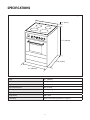 8
8
-
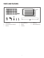 9
9
-
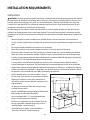 10
10
-
 11
11
-
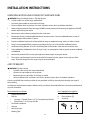 12
12
-
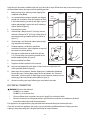 13
13
-
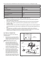 14
14
-
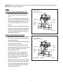 15
15
-
 16
16
-
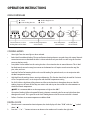 17
17
-
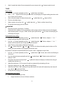 18
18
-
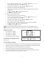 19
19
-
 20
20
-
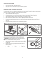 21
21
-
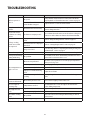 22
22
-
 23
23
-
 24
24
-
 25
25
-
 26
26
-
 27
27
-
 28
28
-
 29
29
-
 30
30
-
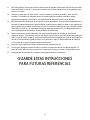 31
31
-
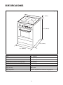 32
32
-
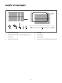 33
33
-
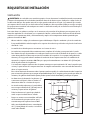 34
34
-
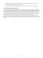 35
35
-
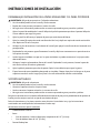 36
36
-
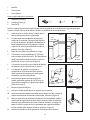 37
37
-
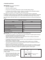 38
38
-
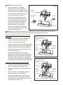 39
39
-
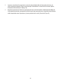 40
40
-
 41
41
-
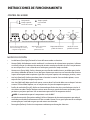 42
42
-
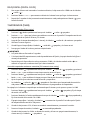 43
43
-
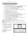 44
44
-
 45
45
-
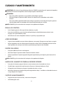 46
46
-
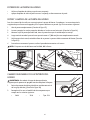 47
47
-
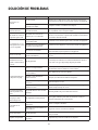 48
48
-
 49
49
-
 50
50
-
 51
51
-
 52
52


Magic Chef MCSRE24S El manual del propietario
- Categoría
- Cocinas
- Tipo
- El manual del propietario
En otros idiomas
- English: Magic Chef MCSRE24S Owner's manual
Documentos relacionados
Otros documentos
-
Avanti DER20P3S El manual del propietario
-
Avanti ER20P3SG Manual de usuario
-
Estate MGR5605W Manual de usuario
-
Whirlpool AGR4433XDW0 Guía de instalación
-
Maytag MGR5605WB Installation Instructions Manual
-
Avanti ER2402CSS Manual de usuario
-
Avanti ER2003CB Manual de usuario
-
-