Craftsman 572.530331 Instrucciones de operación
- Tipo
- Instrucciones de operación

[RAFTSMAN~
Flex-Shaft Attachment Instructions
Model 572.530331
Safety Rules for Flex-Shaft
f,i&"jWma
Read and understa.nd the ~ool
.__ - manual and
these
Instructions for
the
use
of
this accessory with
yow tool.
Fanure
to
follow
aI nstnJ:tilns
listed
below
may
result
in
serious
~rpy
e
Wear
ANSI
CGOJIiant
eye
protection.
The
aperattI1
of any
oower
tool
can
result in
faeIgn
objects
be
n9
thrown
into the eyes.
00
not
operate the flexible shaft with a sharp or
muftiple bends.
Over
bending the shaft can
generate excessive heat on
the jacket or hand piece and
may cause the flexible shaft
ID
(fsengage from tool. The
rnmimum recommended
oend
radius is
5"
Always
hold the hand piece firmly in your hands
during
start-up. Thereaction torque of the motor, as
it
accelerates
to
full
speed, can cause the shaft to
twist
Not
for
use
with
router bits or other large diameter
cutting bits. Large diameter cutting bits can cause
kickback and loss of control when used with the
flexible shaft.
Do not remove end ferrule while tool is running. The
•- cable will become loOSefrom the jacket and will
uncontrollably whip or lash around.
. For use with Craftsman Rotary Tools
572.610700,
572.610530,
5n.61
0830, 572.610960, 572.610950
572.610880
&
572.610520.
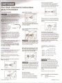
Installation Instructions
It is extremely important to carefully read and follow the
directions below for attaching the flex-shaft to your
rotary tool. This will ensure the tool will function
properly.
Toproperly attach the flex-shaft to the rotary tool,
THREEitems must be removed from the tool: housing
cap, collet nut and collet.
Step
1.
Press the Shaft lock button, unscrew and
remove the collet nut
Step
2.
Unscrew and remove housing cap from tool.
2610915100 11/02
Step
3.
Remove the
collet,
Note: If the collet nut and collet are not
removed from the motor shaft, the tool will
not function properly.
Step
4. lnstall
the driver cap on the motor
shaft and tighten.
".4'P[']~~
To prevenl d~mage t~
~0.!!L_
dO
nof overtIghten dnver
cap. Tighten the driver cap finger tight and then
tighten an additional
1/3
turn
with the wrench
(included with your
rotary
tool ).
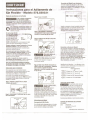
Step
5.
Attach by screwing the collar of the
flex-shaft to the rotary tool. Make sure the
square end of the center core engages the
square hole socket in the driver cap.
t!Ui'iit.l~'
Do not pull. out c~nter core
to engage IOtadrtver cap.
This could cause disengagement of center core
from handpiece. If tool stops when shaft is bent,
center core may be lodged in driver cap. Loosen
shaft and remove core from driver cap. Then
screw flexible shaft onto rotary tool housing
again.
Operating Instructions
Disengagement of the Flex-Shaft
The flexible shaft may become disengaged if
the motor of your rotary tool is not elevated
higher than the working end of the flex-shaft.
Collet and Accessory Assembly
Thecollet assembly consists of a collet nut and
collet. Usethe collet nut and collet that were
removed from your tool in step 2 and 3 and insert
them into the tip of the flex-shaft handpiece.
Insertan accessory or bit as deeply as possible to
avoid wobble during use. Withthe shaft lock button
engaged on the flex-shaft handpiece retighten the
collet nut.
Collet Removal and Replacement
Fourdifferent size collets (sold separately) to
accommodate different shank sizes are available for
your flex-shaft. Toinstall a different collet, remove
the collet nut and old collet. Insert the unslotted end
of the collet in the hole in the end of the flex-shaft,
Replacecollet nut on the shaft. Always use the
collet which matches the shank size of the
accesso'L't'Q.!!.Jllan to use. i'JelleLJoIce_alar.ger
diameter shank into a collet.
Collet Identification - Collet size can be
identified bythe ring(s) on the back end of
collet.
/ Identification rings
~ 1/32"
Collet has one
(1)
ring.
~ 1/16"
Collet has two
(2)
rings.
@dID
3/32"
Collet has three
(3)
rings.
~ 1/8"
Collet has no rings.
Flexible Shaft Lubrication
fil§4'iit.#'
Theflex-shaft should be
lubricated after every
25-30
hours of use.To lubricate, unscrew the flex-shaft
assembly from the motor housing. Pullthe center
core out of the flex-shaft assembly.Wipe a very
thin film of automotive wheel bearing grease on to
the center core and reinsert back into the shaft. To
prevent damage to tool do not over grease
shaft. Toomuch grease will cause the unit to
overheat.
Reattachthe flex-shaft to the rotary tool.
Contents of
572.530331
Flex-Shaft Attachment
Oty. Description
1 Flex-Shaft Assembly (42"
long)
1 Driver Cap
PRINTED IN U.S.A.

I:RAFTSMAN®
Instrucciones para el Aditamento de
Eje Flexible - Modelo 572.530331
Reglas de seguridad para el Eje Flexible
lea
y
entienda el manual de
la herramienta y estas
instrucciones para el uso de este accesorio en la
herramienta. Si no se siguen todas las instrucciones
indieadas a
continuacion
podrian oeasionarse
lesiones
personales serias.
Use protectores oculares que cumplan con
e::!1
las normas ANSI.
La
operaciOn de cualquier
~ herramienta
electrica
puede disparar objetos
extraiios a los ojos.
A
jADVERTENCIA!
No opere el eje flexible
con una flexion aguda ni
con multiples flexiones.
EI exceso de flexion del
eje puede generar calor
excesivo en el ferro
0
en el
mango y hacer que el eje .
flexible se desenganche de la herramienta. EI radio
minima de doblez recomendado es 127mm/5".
Siempre sostenga el mango firmemente en la mana
durante el arranque. EI eje pod ria torcerse por
reaccion al torque (par) del motor al acelerar para
aleanzar la veloeidad maxima.
No es para usar con brocas fresadoras u otras
brocas cortadoras de diametro grande. Las brocas
cortadoras de
diarnetro
grande pueden patear de
retroceso y hacer perder el control de la herramienta
cuando se usa el eje flexible.
No quite el casquillo del extremo cuando la
herramienta este funcionando. EI cable se
sonara
del
forro y
dara
latigazos ineontroladamente al rotar.
Para uso en Herramientas Rotativas Craftsman
572.610700, 572.610530, 572.610830, 572.610960,
572.610950,572.610880 Y572.610520.
Instrucciones para la Instalacion
Para asegurarse que el eje flexible funeione
adecuadamente en la herramienta rotativa, es muy
importante leer y seguir las instrucciones de
ensamblaje que se indican a
contnuacon.
Para instalar el eje flexible adecuadamente en la
herramienta rotativa, deben sacarse TRES piezas de la
herramienta: EI anillo tapa del casco, la tuerea del
mandril y el mandril.
Paso
1:
Presione el seguro del eje
y
saque
la tuerca del mandril.
Paso
2:
Desenrosque el anillo que tapa el casco
de la herramienta,
Paso
3:
Saque el mandril.
Nota:
La
herramienta no funcionara
adecuadamente si no
se saca
la tuerea del
mandril
y
el mandril del eje del motor.
Paso
4:
Instale la tapa del eje en
el
eje del
motor
y
ajustela.
Para evitar daiios a la
herramienta, no
sobreajuste la tapa. Ajustela con los dedos y
despues
1/3 de vuelta adieional con la lIave.
(La lIave viene ineluida en el juego de
herramienta rotative).
A
jCUIDADO!
Paso
5:
Instale el eje flexible enroscando su
collar en el eje de la herramienta. Asegurese
que el extremo cuadrado del nueteo
enganche en el orificio cuadrado del cubo en
la tapa del eje.
t!JGli1j.fu.:.a
No j.ale el
nucleo
del eje
flexible para
engancharlo en la tapa del eje porque el
nucleo
podria zafarse del mango. Si la
herramienta se detiene cuando el eje
esta
flexionado, el
nucleo
pod ria quedar atrapado en
la tapa del eje del motor. Afloje el eje y saque el
nucleo
de la tapa del eje del motor. luego
vue
Iva
a enrosear el eje flexible en el casco de la
herramienta rotativa.
Instrucciones para Ooerar
Desenganche del Eje Flexible
EI eje flexible pod
ria
desengancharse si el motor
de la herramienta rotativa no esta mas elevado
que el extremo de trabajo del eje flexible.
Ensamblaje del Mandril
y
sus Accesorios
EI mandril consiste de una tuerca y del mandril
propiamente. Tome el mandril
y
su tuerca que se
sacaron en los pasos 2 y 3 e msertelos en la punta
del mango del
eje
flexible.
Inserte un accesorio
0
broea tan adentro como sea
posible para evitar que bambolee durante el uso.
VueIva a ajustar el mandril enganehando el boton
del seguro en el mango del eje flexible.
Desmontaje
y
Montaje del Mandril
Para aeomodar
vastaqos
de diferentes tamaiios en
el eje flexible, se venden
por
separado
rnandrles
de
cuatro tamaiios. Para eambiar el mandril, saque la
tuerea del mandril existente y el mandril. Inserte el
extremo sin ranuras del mandril en el orifieio en el
extremo del eje flexible. Reinstale la tuerea del
mandril en el eje. Siempre use el mandril del
dlamefm
adecuado para el
vastaqo
del accesorio
que se va a usar. Nunca fuerce un
vastaqo
de
mayor diarnetro en un mandril
ldennticaclon de Mandriles: - Los oiarnetros de los
mandriles pueden identificarse por los anillos en el
extremo posterior del mandril.
Anillos Identificadores
/
@d:l
EI Mandril de 1/32" tiene un (1) anillo.
@dD
EI Mandril de
1/16"
tiene dos (2).
~ EIMandril de 3/32" tiene tres (3) anillos.
@bJ
EIMandril de
1/8"
no tiene anillos.
lubricacion del Eje Flexible
f!iliili.fli.f.D
EI eje flexible debe lubriearse
- ...... - cad a 25 a 30 horas de uso.
Para lubriearlo, desenrosque el eje flexible del
casco del motor. Saque el nucleo del eje flexible,
trotele grasa para cojnete de rueda de autornovil
para impregnarle una pelfeula fina de grasa y
reinsertelo en el eje. Para evitar danar el eje, no
eng rase el nucteo exeesivamente porque el
exeeso de grasa recalentara el eje.
Reinstale el eje flexible en la herramienta rotativa.
Contenido del Aditamento de Eje Flexible
572.530331
Cant.
1
1
Descripci6n
Eje flexible
(107cm/42")
Tapa para
eje
IMPRESO EN LOS EE.UU.

6
\
7
1
~
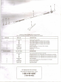
ORDER BY PART NUMBER, NOT CODE NUMBER
PIDA POR NUMERO DE PIEZA, NO POR NUMERO DE C6DIGO
CODE NO. PART NO. DESCRIPTION
1 2615297355
Collet Nut (Not included)
2
~
480
--
-
1/8" Collet available as Accessory (Not mcluded)
-
481
3/32" Collet available as Accessory (Not included)
482
1/16" Collet available as Accessory (Not included)
483
1/32" Collet available as Accessory (Not included)
3 2610914485
Handpiece Cap
4 90962
Wrench Available as Accessory (Not included)
5
2610914543
Flexible Shaft Core
6
2610915085
Overthrow Nut Assembly
7
529417870
Driver Cap
NO. DE CODIGO NO. DE PIEZA DESCRIPCION
1
2615297355
Tuerca del portaherramienta (no incluida)
2
480
Portaherramienta de 1/8" disponible como accesorio (no incluido)
481
Portaherramienta de 3/32" disponible como accesorio (no incluido)
482
Portaherramienta de 1/16" disponible como accesorio (no incluido)
483
Portaherramienta de 1/32" disponible como accesorio (no incluido)
3
2610914485
Tapa del Mango
4 90962
Llave de tuerca disponible como accesorio (no incluida)
5 2610914543
Nucleo del eje flexible
6 2610915085
Conjunto de tuerca
7 529417870
Tapa del impulsor
For Replacement Parts Call Sears.
Para piezas de repuesto lIame a Sears.
1-800-4-MY-HOME®
(1-800-469-4663)
-
 1
1
-
 2
2
-
 3
3


