
Installation and Operation Guide
Model #: LTS-3HP
3.5kW / 120V
Note: Restricted to sink applications only. Please read manual
completely prior to installing your unit to understand if this
unit is suitable for your application.

OVERVIEW
This manual must be read carefully before attempting to install the water heater. If you do not follow the safety rules or the
instructions outlined in this manual, the unit may not operate properly and it could cause property damage, serious bodily injury
or death.
Atmor will not be liable for any damages because of failure to comply with the installation and operating instructions
outlined in this manual or because of improper use. Improper use includes the use of this appliance to heat any liquid other than
water.
Failure to comply with the installation and operating instructions or improper use voids the warranty. Never
remove the unit’s cover unless the electricity is turned off.
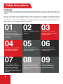
Safety Instructions
1
01
04
07
03
06
09
02
05
08
The water heater must
be installed by a licensed
electrician and in compliance with
all local electrical and building
regulations.
The heater must be installed
according to the installation
instructions (see figures).
The plumbing installation
requires metal or reinforced
pipes that can withstand a
minimum pressure of 8 bar.
(Other types of pipes will cause
damage.)
Caution: The appliance must be
grounded.
The plumbing installation
must be completed before the
electrical installation.
Do not install the heater where
it may be subjected to direct
sunlight, rain and/ or a constant
spray of water.
A dedicated circuit breaker
must be installed on the power
distribution panel.
The heater operates at a
minimum water flow rate of
0.5 gallon/minute.
Always contact your
local authorized licensed
proffessional for service.

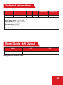
Technical Information
Model Guide - kW Output
2
Model Wattage Voltage Amperage
Phase
Circuit breaker
size
Required wire
size
LTS-3HP 3.5 kW 120 27 1 30 10 AWG
Minimum water flow to activate unit: 0.5 GPM
Nominal water volume: 0.11 gal (0.42l)
Working pressure: 0.5 -8 bar (7 -115 psi)
Tested pressure: 16 bar (230 psi)
Water connections: 1/2” NPT
Dimensions (in) (H x W x D): 7.2 x 11.8 x 4.3
Weight (Ib): 3.4
Model 120V 110V
LTS-3HP 3.5 kW 3.0 kW
Wattage based on maximum voltage.

01
05
06
02
04
03
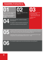
Remove the appliance covers
(Figure 2).
Connect the Pressure Relief Device
(PRD) to the unit (Fig1) Note:
IMPORTANT – do not discard
this step. A PRD must be
installed.
Connect the water inlet hose to the entry point of the heater (left side inlet), and connect
the outlet hose to the water outlet. Use a hose that can withstand a minimum pressure of
4 bars. Using any other type of hose will cause damage (Figure 5).
Residential plumbing systems with unstable pressure or pressure above 5 bar require
the application of a pressure stabilizer valve, set to 4 – 5 bars.
Do not install the appliance with water inlets and outlets at the top (Figure 6)
Mount unit to wall with 4 screws at the marked
points (Figure 4)
The appliance must be mounted horizontally, with
water inlets and outlets at the bottom (Figure 5)
1. Mount ground plate to wall.
2. Pull wires through.
3. Cut out hole in back of unit
(Right/Left back) and pass
wires through
(Figure 3)
Assembly Instructions
3

N
L1G
2
3 4
65
1
*
L1G
G
N
N
L1
4
G = Green or Yellow
N = White
L1 = Black
Rubber
Cold Hot
PRD
3
3.5kW

5
07
1009
13
08
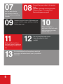
It is recommended that the appliance electrical
connections be tested once a year by a qualified
technician.
Run the water flow for
one minute to check for
leakage before connecting
to power.
Reattach the front cover of the heater and
secure it with 4 screws and then slide the
bottom gray cover
Connect the power cable to the terminal
block.
Caution: The heater must be grounded.
Reference figure *3 on page 4 and
Electrical diagram on page 6
When installed outdoors,
the heater must be placed in
sealed waterproof electrical
box.
Make sure that the
appliance is filled with water
before connecting power.
(Repeat step 7)
11 12
Do not install the heater where
it may be subject to direct
sunlight.

1
L1
E(G)
N
6
Electrical Diagram
1. Terminal block
2. Thermal cut-out with reset
3. Thermal cut-out
4. Light
5. Switch On / Off
6. Relay
7. Heating element
8. Read sensor
* 3.5kW/120V = 3.0kW/110V
3.5kW (120V)* - Install Line 1 (L1), E(G)-Ground, N (Neutral)

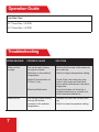
Operation Guide
Troubleshooting
7
PROBLEM ISSUE POSSIBLE CAUSE SOLUTION
Water not hot
enough.
Too much water flowing
through the heater.
Reduction in the ambient
temperature.
Water Pressure below of
0.5 bar (7 psi).
Electrical Malfunction.
Reduce the flow rate of the water via
the outlet tap.
Switch to higher temperature setting.
Check if the main water line stop
valve is fully open and that there
are no other restrictions in the water
supply line.
Have the Heater unit check by a
qualified eIectrician or contact your
local authorized distributor.
Flow Rate Chart
35º F Temp Rise - 0.6 GPM
45º F Temp Rise - 0.5 GPM
Water too hot. Not enough water flowing
through the heater.
Increase in the ambient
temperature.
Increase the flow rate via the outlet
tap.
Switch to lower temperature setting.

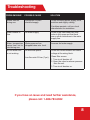
Troubleshooting
8
PROBLEM ISSUE POSSIBLE CAUSE SOLUTION
Heater shut off
during use.
Interruption of main
electrical supply.
Check incoming power supply, MCB,
switches and supply cabling.
If problem persists, call your local
manufacturer for assistance.
Water ceases to
flow.
No water supply. Check if the main water line stop
valve is fully open and that there
are no other restrictions in the water
supply line.
Water temperature
varies from hot to
cold during use.
Water pressure has
dropped below min. level.
Increase hot water supply.
No hot water/Unit
is not working.
No electrical power.
Low flow rate 0.5 bar (7 psi).
Check the circuit breaker and check
voltage at the wiring block.
Clean filter screen:
1. Turn circuit breaker off.
2. Open the valve to release pressure
from the unit.
3. Turn circuit breaker on.
If you have an issue and need further assistance,
please call: 1-888-783-6082

9
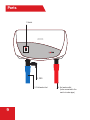
ON
OFF
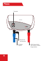
3. Cold water inlet
2. PRD
4. Hot water outlet
(to be connected to the
main hot water pipe)
1. Switch
9
Parts

10

LIMITED WARRANTY
Manufacturer warrants to the original owner that our instant water heaters will be free from
defects in workmanship and material for a period of TWO YEARS from the date of purchase,
and free from leakage for a period of SEVEN YEARS from the date of purchase. Should any
part(s) prove to be defective during this period, Manufacturer will be responsible for replacement
of the defective part(s) only. Manufacturer is not responsible for labor charges or any incidental
or consequential expenses.
Should the owner wish to return the water heater for repair, the owner must first secure a written
authorization from Manufacturer. The owner shall be required to show proof of purchase date
and to pay all transportation costs to return the defective part(s) or water heater for repair
or replacement. Warranty is void if: (i) water heater has been installed or used improperly;
(ii) design has been altered in any way; (iii) water heater has been installed and/or serviced by
someone other than a licensed electrician ; (iv) or if the water heater has been installed or used
in contradiction to installation instructions, applicable laws and/or ordinances.
Distributed by:
PARAGON GROUP USA LLC
Englewood, NJ 07631
1-888-783-6082
P.N. 196184
Call us rst and let our service team help!
DO NOT RETURN TO STORE
Have questions about your unit
or need service?
Please call:
1-888-783-6082
or mail:
Our staff is ready to provide
you with assistance.
Monday – Friday, 9AM – 5PM EST

Instalación y guía de funcionamiento
Modelo #: LTS-3HP
3,5 kW / 120V
Nota: Limitado solo para aplicaciones de lavabos. Lea el
manual completamente antes de instalar su unidad para
comprender si esta unidad es adecuada para su aplicación.

DESCRIPCIÓN GENERAL
Este manual se debe leer atentamente antes de intentar instalar el calentador de agua. Si usted no cumple las reglas de
seguridad o las instrucciones detalladas en este manual, la unidad puede no funcionar adecuadamente y puede causar daños a
la propiedad, lesiones corporales graves o la muerte.
Atmor no será responsable de los daños ocasionados por no cumplir las instrucciones de instalación y funcionamiento detallados
en este manual o por el uso inadecuado. El uso inadecuado incluye el uso de este artefacto para calentar cualquier líquido que no
sea agua. No cumplir las instrucciones de instalación y funcionamiento o usar el artefacto de manera
inadecuada anula la garantía. Nunca retire la cubierta de la unidad a menos que la electricidad esté
desconectada.
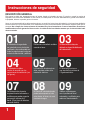
Instrucciones de seguridad
1
01
04
07
03
06
09
02
05
08
El calentador de agua debe
ser instalado por un electricista
certificado y en conformidad con
todas las regulaciones locales en
materia de electricidad y edificios.
El calentador se debe
instalar de acuerdo con las
instrucciones de instalación (ver
las figuras).
La instalación de plomería
requiere tuberías reforzadas o
metálicas que puedan soportar
una presión mínima de 8
bares. (Otros tipos de tuberías
causarán daños).
Precaución: el artefacto se debe
conectar a tierra.
La instalación de plomería se
debe completar antes de la
instalación eléctrica.
No instale el calentador donde
pueda estar expuesto a la luz
solar directa, la lluvia o el rocío
constante de agua.
Se debe instalar un disyuntor
dedicado en el panel de distribución
de la alimentación.
El calentador funciona a
una tasa de flujo mínima de
0.5 galones/minuto.
Siempre comuníquese
con su profesional local
autorizado y certificado para
realizar el mantenimiento.

Información técnica
2
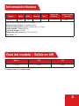
Guía del modelo – Salida en kW
Modelo Vataje Voltaje
Amperaje Fase
Tamaño del
disyuntor
Tamaño de cable
requerido
LTS-3HP 3,5 kW 120 27 1 30 10 AWG
Flujo mínimo de agua para activar la unidad: 0,5 GPM
Volumen de agua nominal: 0,11 galones (0,42 l)
Presión de funcionamiento: de 0,5 a 8 bares (de 7 a 115 psi)
Presión probada: 16 bares (230 psi)
Conexiones de agua: 1/2” NPT
Dimensiones (pulg.) (A x A x P): 7,2 x 11,8 x 3,55
Peso (libras): 3,4
Modelo 120V 110V
LTS-3HP 3,5 kW 3,0 kW
El vataje se basa en el voltaje máximo.

01
05
06
02
04
03
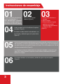
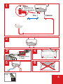
Retire las cubiertas del
artefacto (Figura 2).
Conecte el dispositivo de alivio de
presión a la unidad (Fig. 1).
Nota: IMPORTANTE – No omita
este paso. Se debe instalar un
dispositivo de alivio de presión.
Conecte la manguera de entrada de agua al punto de entrada del calentador (entrada del
lado izquierdo) y conecte la manguera de salida a la salida de agua. Use una manguera
que pueda soportar una presión mínima de 4 bares. El uso de cualquier otro tipo de
manguera causará daños (Figura 5).
Los sistemas de plomería residenciales con una presión inestable o una presión que
supere los 5 bares requieren la aplicación de una válvula estabilizadora de presión,
fijada en 4 a 5 bares.
No instale el artefacto con las entradas y salidas de agua en la parte superior
(Figura 6).
Instale la unidad con los 4 tornillos en los puntos
marcados (Figura 4).
El artefacto se debe instalar horizontalmente, con
las entradas y salidas de agua en la parte inferior
(Figura 5).
1. Instale la placa de tierra a
la pared.
2. Jale los cables.
3. Corte el orificio en la parte
posterior de la unidad
(Derecha/Izquierda posterior)
y pase los cables
(Figura 3).
Instrucciones de ensamblaje
3

N
L1G
2
3 4
65
1
*
L1G
G
N
N
L1
4
Goma
Dispositivo de
alivio de presión
3
3,5 kW
Frío Caliente
G = Verde o amarillo
N = Blanco
L1 = Negro

5
07
1009
13
08
Se recomienda que las conexiones eléctricas del artefacto
sean probadas una vez al año por un técnico certificado.
Deje correr el agua durante un
minuto para verificar si hay fugas
antes de conectar el artefacto al
suministro eléctrico.
Vuelva a colocar la cubierta frontal del
calentador y asegúrela con 4 tornillos, y luego
deslice la cubierta gris inferior.
Conecte el cable de alimentación al bloque
de terminales.
Precaución: el calentador debe estar
conectado a tierra.
Consulte la figura 3 en la página 4 y el
diagrama eléctrico en la página 6.
Cuando el sistema se instala al
aire libre, el calentador se debe
colocar en una caja eléctrica
sellada a prueba de agua.
Asegúrese de que el artefacto
esté lleno de agua antes de
conectar el suministro eléctrico.
(Repita el paso 7).
11 12
No instale el calentador donde
pueda estar expuesto a la luz
solar directa.

1
L1
E(G)
N
6
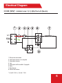
Electrical Diagram
1. Bloque de terminales
2. Interruptor térmico con reajuste
3. Interruptor térmico
4. Luz
5. Interruptor de Encendido / Apagado
6. Relé
7. Resistencia
8. Sensor de lectura
* 3,5 kW / 120V = 3,0 kW / 110V
3,5 kW (120V)* - Instalar Línea 1 (L1), E(G)-Tierra, N (Neutro)

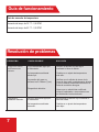
Guía de funcionamiento
7
Guía de aumento de temperature
Aumento de temp. de 35 °F - 0,6 GPM
Aumento de temp. de 45 °F - 0,5 GPM
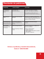
Resolución de problemas
PROBLEMA CAUSA POSIBLE SOLUCIÓN
El agua no está lo
suficientemente
caliente.
Fluye demasiada agua por
el calentador.
La temperatura ambiente
disminuyó.
La presión del agua no
alcanza los 0.5 bares (7 psi).
Desperfecto eléctrico.
Reducir la tasa de flujo del agua
mediante la llave de salida.
Cambiar a un ajuste de temperatura
más alto.
Verificar que la válvula de cierre de la
línea de agua esté completamente abierta
y que no existan otras restricciones en la
línea de suministro de agua.
Hacer que un electricista certificado
revise el calentador o comunicarse con
su distribuidor local autorizado.
El agua está No fluye suficiente agua por
demasiado caliente. el calentador.
La temperatura ambiente
aumentó.
Incrementar la tasa de flujo mediante la
llave de salida.
Cambiar a un ajuste de temperatura
más bajo.

Resolución de problemas
8
Si tiene un problema y necesita más asistencia,
llame al: 1-888-783-6082
PROBLEMA CAUSA POSIBLE SOLUCIÓN
El calentador se
apaga durante
el uso.
Interrupción del
suministro eléctrico.
Revisar el suministro de energía,
disyuntor, interruptores y cableado.
Si el problema persiste, llame a su
fabricante local para obtener asistencia.
El agua deja de
correr.
Interrupción del suministro
de agua.
Verificar que la válvula de cierre de la
línea de agua esté completamente abierta
y que no existan otras restricciones en la
línea de suministro de agua.
La temperatura del
agua varía de caliente
a fría durante el uso.
La presión del agua ha
caído por debajo del nivel
mínimo.
Aumentar el suministro de agua
caliente.
No sale agua
caliente/La unidad
no funciona.
Falta de energía eléctrica.
Tasa de flujo baja, 0.5 bares
(7 psi).
Verificar el disyuntor y el voltaje en el
bloque de cableado.
Limpiar la rejilla del filtro:
1. Apagar el disyuntor.
2. Abrir la válvula para liberar la presión
de la unidad.
3. Encender el disyuntor.

9
ON
OFF
3. Entrada de
agua fría
2. Dispositivo de
alivio de presión
4. Salida de agua caliente
(para conectar a la tubería
de agua caliente)
1. Interruptor
9
Piezas

10

GARANTÍA LIMITADA
Fabricante garantiza al propietario original de nuestros calentadores de agua instantáneos la ausencia
de defectos de fabricación y material durante un período de DOS AÑOS a partir de la fecha de compra,
y la ausencia de fugas durante un período de SIETE AÑOS a partir de la fecha de compra. Si alguna
pieza resultara defectuosa durante este período, Fabricante será responsable del reemplazo de la pieza
defectuosa únicamente. Fabricante no se responsabilizará por los costos de mano de obra o cualquier
gasto incidental o consecuente.
Si el propietario desea devolver el calentador para su reparación, el propietario primero debe obtener
una autorización escrita de Fabricante. Se requiere que el propietario muestre una prueba de la fecha
de compra y pague todos los costos de transporte para devolver la pieza defectuosa o el calentador para
su reparación o reemplazo. La garantía no será válida si: (i) el calentador de agua ha sido instalado o
usado de manera inadecuada; (ii) el diseño ha sido alterado de cualquier manera; (iii) la instalación o el
mantenimiento del calentador estuvo a cargo de una persona distinta de un electricista habilitado; (iv) o si
el calentador ha sido instalado o usado en contradicción con las instrucciones de instalación, las leyes u
ordenanzas aplicables.
Distribuido por:
PARAGON GROUP USA LLC
Englewood, NJ 07631
1-888-783-6082
P.N. 196184
¡ALTO!
¡Primero llámenos y deje que
nuestro equipo de asistencia lo ayude!
NO DEVUELVA EL CALENTADOR
A LA TIENDA
¿Tiene preguntas acerca de su unidad
o necesita asistencia?
Llame al:
1-888-783-6082
o envíe un correo electrónico a:
Nuestro personal está preparado para asistirlo.
De lunes a viernes, de
9 a.m. a 5 p.m. Hora Estándar del Este
-
 1
1
-
 2
2
-
 3
3
-
 4
4
-
 5
5
-
 6
6
-
 7
7
-
 8
8
-
 9
9
-
 10
10
-
 11
11
-
 12
12
-
 13
13
-
 14
14
-
 15
15
-
 16
16
-
 17
17
-
 18
18
-
 19
19
-
 20
20
-
 21
21
-
 22
22
-
 23
23
-
 24
24


