Hampton Bay 61393 Instrucciones de operación
- Categoría
- Ventiladores domésticos
- Tipo
- Instrucciones de operación


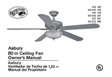
52” Clarington
Ceiling Fan by Hampton Bay
3-Speed Reverse Function for
Year-Round Comfort and Savings
Steeper Blade Pitch for Greater
Air Movement
Tri-Mount Installation
Handheld Remote Control
QUESTIONS, PROBLEMS, MISSING PARTS:
Before returning to your local Home Depot, please call our
Customer Service Team at 1-877-527-0313 or visit www.homedepot.com.
Please reference your SKU (503 837 gilded mahogany)
or UPC (082392 613938R gilded mahogany).
Thank you for purchasing this Hampton Bay ceiling
fan. This product has been manufactured with the
highest standards of safety and quality. The nish
of this fan is weather resistant, but over time will
naturally weather and fade.
Safety Rules ...............................................1
Unpacking Your Fan .................................2
Installing Your Fan ...................................3
Operating Your Fan .................................. 10
Operating Your Remote Control .............11
Care of Your Fan ....................................... 12
Troubleshooting .........................................12
Specications .............................................13
Warranty Information ..............................14
Table of Contents
UL model no. : 52-BGM

1. To reduce the risk of electric shock, insure electricity
has been turned off at the circuit breaker or fuse box
before beginning.
2. All wiring must be in accordance with the National
Electrical Code ANSI/NFPA 70-1999 and local electrical
codes. Electrical installation should be performed by a
qualied licensed electrician.
3. WARNING: To reduce the risk of re or electric shock, this fan
should only be used with fan speed control part no.: UC7067RK,
manufactured by Rhine Electronic Co., Ltd. or part no.: FAN-
18R manufactured by Chia Wei Electric Co., Ltd.
4. CAUTION: To reduce the risk of personal injury, use only
the screws provided with the outlet box.
5. The outlet box and support structure must be securely
mounted and capable of reliably supporting a minimum of
35 pounds. Use only UL Listed outlet boxes marked “FOR
FAN SUPPORT.”
6. The fan must be mounted with a minimum of 7 feet
clearance from the trailing edge of the blades to the oor.
7. Do not operate reversing switch while fan blades are in mo-
tion. Fan must be turned off and blades stopped before re-
versing blade direction.
8. Avoid placing objects in path of the blades.
9. To avoid personal injury or damage to the fan and
other items, be cautious when working around or
cleaning the fan.
10. Do not use water or detergents when cleaning the fan or fan
blades. A dry dust cloth or lightly dampened cloth will be
suitable for most cleaning.
11. After making electrical connections, spliced conductors
should be turned upward and pushed carefully up into
outlet box. The wires should be spread apart with the
grounded conductor and the equipment-grounding
conductor on one side of the outlet box.
12. Electrical diagrams are for reference only. Light kits that are
not packed with the fan must be UL Listed and marked suit-
able for use with the model fan you are installing. Switches
must be UL General Use Switches. Refer to the instructions
packaged with the light kits and switches for proper assembly.
13. All set screws must be checked and retightened where neces-
sary before installation.
Safety Rules 1.
READ AND SAVE THESE INSTRUCTIONS
TO REDUCE THE RISK OF FIRE, ELECTRIC SHOCK OR PERSONAL
INJURY, MOUNT TO OUTLET BOX MARKED ACCEPTABLE FOR FAN
SUPPORT AND USE SCREWS PROVIDED WITH THE OUTLET BOX.
TO REDUCE THE RISK OF SHOCK. THIS FAN MUST BE INSTALLED
WITH AN ISOLATION WALL CONTROL/SWITCH.
TO REDUCE THE RISK OF PERSONAL INJURY, DO NOT BEND THE
BLADE BRACKETS (ALSO REFERRED TO AS (“FLANGES”) DURING
ASSEMBLY OR AFTER INSTALLATION. DO NOT INSERT OBJECTS IN
THE PATH OF THE BLADES.

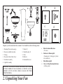
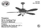
a. Blade Attachment Hardware
(15 screws)
b. Hardware & Balancing Kit
(1 hanging pin, 1 locking pin, 3 plastic
wire connectors)
c. Blade Balancing Kit
d. Close to Ceiling Mounting Hardware
(1 rubber gasket)
7. Blades (5)
8. Blade Brackets (5)
9. Glass
10. Bulbs(2)
11. Hand unit/Receiver
1. Mounting Plate (inside canopy)
2. Downrod and Ball Assembly
3. Canopy
4. Decorative Motor Collar Cover
5. Fan Motor Assembly
6. Light Kit Assembly
2. Unpacking Your Fan
IMPORTANT: THIS PRODUCT AND/OR COMPONENTS ARE COVERED
BY ONE OR MORE OF THE FOLLOWING U.S. PATENTS: 5,947,436;
5,988,580; 5,971,573; 6,010,306; 6,039,541; 6,046,416 AND OTHER
PATENTS PENDING.
Unpack your fan and check the contents. You should have the following items:
d
b
c
a

Installing Your Fan 3.
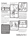
Tools Required
Phillips screw driver, straight slot screw
driver, adjustable wrench, step ladder, and
wire cutters.
Mounting Options
If there isn’t an existing outlet box, then read
the following instructions. Disconnect the
power by removing fuses or turning off
circuit breakers.
Secure the outlet box directly to the building
structure. Use appropriate fasteners and
building materials. The outlet box and its
support must be able to fully support the
moving weight of the fan (at least 35 lbs.)
Do not use plastic outlet boxes.
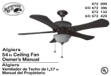
Figures 1, 2, and 3 are examples of different
ways to mount the outlet box.
Outlet Box
Note: You may need a longer downrod to
maintain proper blade clearance when install-
ing on a steep, sloped ceiling. The maximum
angle allowable is 30˚. If the canopy touches
downrod, remove the decorative canopy
bottom cover and turn the canopy 180˚ before
attaching the canopy to the mounting plate.
Outlet Box
To hang your fan where there is an existing
xture but no ceiling joist, you may need an
installation hanger bar as shown in Figure 4
(available at your Hampton Bay retailer).
TO REDUCE THE RISK OF FIRE, ELECTRIC
SHOCK OR PERSONAL INJURY, MOUNT
FAN ONLY TO AN OUTLET BOX MARKED
ACCEPTABLE FOR FAN SUPPORT AND
USE THE MOUNTING SCREWS PROVIDED
WITH THE OUTLET BOX. OUTLET BOXES
COMMONLY USED FOR THE SUPPORT OF
LIGHTING FIXTURES MAY NOT BE ACCEPT-
ABLE FOR FAN SUPPORT AND MAY NEED
TO BE REPLACED. CONSULT A QUALIFIED
ELECTRICIAN IF IN DOUBT.
Figure 1
Figure 2
Figure 4
Figure 3

2. Remove the mounting plate from the
canopy by loosening the four screws on
the top of the canopy. Remove the two
non-slotted screws and loosen the slotted
screws. This will enable you to remove the
mounting plate (Figure 6).
4.
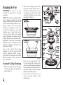
Hanging the Fan
REMEMBER to turn off the pow-
er. Follow the steps below to hang your
fan properly.
NOTE: This ceiling fan is supplied with two
types of hanging assemblies; the standard
ceiling installation using the downrod with
ball and socket mounting, and the “close-to-
ceiling” mounting. The “close-to-ceiling”
mounting is recommended in rooms with
less than 8-foot ceilings or in areas where
additional space is desired from the oor
to the fan blades. When using standard
downrod installation, the distance from the
ceiling to the bottom of the fan blades will be
approximately 15 inches. The “close-to-ceiling”
installation reduces the distance from the
ceiling to the bottom of the fan blades to
approximately 8 inches.
Once you have decided which ceiling
installation you will use, proceed with the
following instructions. Where necessary,
each section of the instructions will note the
different procedures to follow for the two
types of installation.
Standard Ceiling Mounting
1. Remove the canopy ring from the canopy
by turning the ring to the right until it
unlocks (Figure 5).
Figure 5
Figure 6
Figure 7
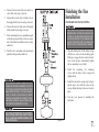
3. Route the wires exiting the top of the
fan motor through the decorative motor
collar cover then the canopy ring. Make sure
the slot openings are on top. Route the wires
through the canopy and then through the
ball/downrod assembly (Figure 7).
4. Loosen, but do not remove, the set
screw on the collar on the top of the
motor housing.

will enable you to remove the mounting
bracket (Figure 6).
3. Remove the decorative canopy bottom cov-
er from the canopy by depressing the three
studs (Figure 8).
4. Remove three of the six screws and lock-
washers (every other one) securing the mo-
tor collar to the top of the fan motor housing
(Figure 9).
5. Place the rubber gasket over the remain-
ing three screws, route the wires exiting
the top of the fan motor through the canopy
ring (make sure the slot openings are on
top), then proceed to place the ceiling can-
opy over the collar at the top of the motor
(Figure 10).
6. Align the mounting holes with the holes
in the motor and fasten, using the three
screws and lock-washers removed in step 4
(Figure 10). 5.
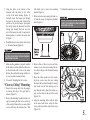
5. Align the holes at the bottom of the
downrod with the holes in the collar
on top of the motor housing (Figure 7).
Carefully insert the hanger pin through
the holes in the collar and downrod. Be
careful not to jam the hanger pin against
the wiring inside the downrod. Insert the
locking pin through the hole near the
end of the hanger pin until it snaps into its
locked position, as noted in the circle inset
of Figure 7.
6. Re-tighten the set screws on the collar on top
of the motor housing (Figure 8).
7. Make sure the grommet is properly installed
in the collar cover, then slide the collar cover
on the downrod until it rests on the motor
housing. Be sure that the canopy and the col-
lar cover are both oriented correctly.
8. Proceed to “Installing the Fan” section.
“Close-to-Ceiling” Mounting
1. Remove the canopy ring from the canopy
by turning the ring to the right until it
unlocks (Figure 5).
2. Remove the mounting bracket from the can-
opy by loosening the four screws on the top
of the canopy. Remove the two non-slotted
screws and loosen the slotted screws. This
FAILURE TO PROPERLY INSTALL SET SCREWS
IN STEP 7 COULD RESULT IN FAN LOOSENING
AND POSSIBLY FALLING.
FAILURE TO PROPERLY INSTALL SET SCREWS
IN STEP 6 COULD RESULT IN FAN LOOSENING
AND POSSIBLY FALLING. Figure 8 Figure 9
Figure 10
7. Tighten the mounting screws securely.

6.
WHEN USING THE STANDARD BALL/DOWN-
ROD MOUNTING, THE TAB IN THE RING AT THE
BOTTOM OF THE MOUNTING BRACKET MUST
REST IN THE GROOVE OF THE HANGER BALL.
FAILURE TO PROPERLY SEAT THE TAB IN THE
GROOVE COULD CAUSE DAMAGE TO WIRING.
Installing Fan to
the Outlet Box
WHEN MOUNTING THE FAN ON A SLOPED
CEILING, THE STANDARD BALL/DOWNROD
MOUNTING METHOD MUST BE USED. MAKE
SURE THE MOUNTING BRACKET SLOTS ARE
ON THE LOWER SIDE BY SLIDING THE MOUNT-
ING BRACKET FROM THE TOP DOWN.
1. Pass the 120-volt supply wires through the
center hole in the ceiling mounting bracket
as shown in Figure 7.
2. Install the ceiling mounting plate on the out-
let box by sliding the mounting plate over
the two screws provided with the outlet box
(Figure 11). When using close-to-ceiling
mounting, it is important that the mounting
bracket be level. If necessary, use leveling
washers (not included) between the mount-
ing plate and the outlet box. Note that the
at side of the mounting bracket is toward
the outlet box (Figure 11).
3. Securely tighten the two mounting screws.
4. For additional security, install two wood
screws with at washers (not included)
through outer slots in mounting plate and
into wooden joist. Note: Leave one wood
screw untightened to attach safety cable
from motor.
5. Carefully lift the fan assembly up to the ceil-
ing mounting plate. If using close-to-ceiling
mounting, hang the fan on the hook provid-
ed by utilizing one of the holes at the outer
rim of the ceiling canopy (Figure 11). If us-
Figure 11
THE HOOK AS SHOWN IN FIGURE 11 IS ONLY
TO BALANCE FAN WHILE ATTACHING WIRING.
FAILURE TO HANG AS SHOWN IN FIGURE 11
MAY RESULT IN HOOK BREAKING, CAUSING
THE FAN TO FALL. HOOK MUST PASS FROM
INSIDE TO OUTSIDE OF CANOPY.
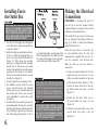
Making the Electrical
Connections
REMEMBER to disconnect the power. If
you feel you do not have enough electrical
wiring knowledge or experience, have your fan
installed by a licensed electrician.
Note: Install the receiver prior to wiring your
fan, see Operating Your Remote Control on
page 11 for details, or follow the instructions
packed with the receiver.
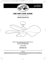
Follow the steps below to connect the fan
to your household wiring. Use the wire
connecting nuts supplied with your fan. Se-
cure the connectors with electrical tape.
Make sure there are no loose strands or
connections.
1. Connect the ground conductor of the 120v
supply (this may be a bare wire or a wire
with green colored insulation) to the green
ground lead(s) of the fan (Figure 12). Con-
nect the fan motor white wire to the sup-
ply white (neutral) wire using a wire nut
(Figure 12).
2. Connect the fan motor white wire to
the receiver white wire using a wire nut
(Figure 12).
3. Connect the fan motor black wire to the
receiver black wire using a wire nut
(Figure 12).
ing standard mounting, seat the hanger ball
in the mounting plate socket. Make sure the
tab on the mounting plate socket is properly
seated in the groove in the hanger ball.

7.
EACH WIRE NUT (WIRE CONNECTOR) SUP-
PLIED WITH THIS FAN IS DESIGNED TO ACCEPT
UP TO ONE 12 GAUGE HOUSE WIRE AND TWO
WIRES FROM THE FAN. IF YOU HAVE LARGER
THAN 12 GAUGE HOUSE WIRING OR MORE
THAN ONE HOUSE WIRE TO CONNECT TO THE
FAN WIRING, CONSULT AN ELECTRICIAN FOR
THE PROPER SIZE WIRE NUTS TO USE.
Figure 12
ELECTRICAL DIAGRAMS ARE FOR REFERENCE
ONLY. OPTIONAL USE OF ANY LIGHT KIT SHALL
BE UL LISTED AND MARKED SUITABLE FOR
USE WITH THIS FAN.
4. Connect the fan motor blue wire to the re-
ceiver blue wire using a wire nut.
5. Connect the receiver red (or black) wire to
the supply black (hot) wire using a wire nut.
6. Connect the receiver white wire to the supply
white (neutral) wire using a wire nut.
7. After connecting the wires, spread them apart
so that the green and white wires are on one
side of the outlet box and black wire is on the
other side.
8. Turn the wire connecting nuts upward and
push the wiring into the outlet box.
Finishing the Fan
Installation
STANDARD CEILING MOUNTING
1. Align the locking slots of the ceiling canopy
with the two screws in the mounting plate.
Push up to engage the slots and turn clock-
wise to lock in place. Immediately tighten
the two mounting screws rmly.
2. Install the remaining two mounting
screws into the holes in the canopy and
tighten rmly.
3. Install the decorative canopy ring by align-
ing the ring’s slots with the screws in the
canopy. Rotate the ring clockwise to lock in
place.
4. You may now proceed to attaching the
fan blades.
WHEN USING THE STANDARD BALL/DOWN-
ROD MOUNTING, THE TAB IN THE RING AT THE
BOTTOM OF THE MOUNTING BRACKET MUST
REST IN THE GROOVE OF THE HANGER BALL.
FAILURE TO PROPERLY SEAT THE TAB IN THE
GROOVE COULD CAUSE DAMAGE TO WIRING.

8.
CLOSE-TO-CEILING MOUNTING
1. Carefully unhook the fan from the mount-
ing bracket and align the locking slots of the
ceiling canopy with the two screws in the
mounting bracket. Push up to engage the
slots and turn clockwise to lock in place. Im-
mediately tighten the two mounting screws
rmly.
2. Install the remaining two mounting screws
into the holes in the canopy and tighten
rmly.
3. Install the decorative canopy ring by align-
ing the ring’s slots with the screws in the
canopy. Rotate the ring clockwise to lock in
place.
4. You may now proceed to attaching the fan
blades.
Attaching the
Fan Blades
NOTE: Your fan blades are reversible. Select
the blade side nish that best accentuates your
decor.
LOCKING SLOTS OF CEILING CANOPY ARE
PROVIDED ONLY AS AN AID TO MOUNTING. DO
NOT LEAVE FAN ASSEMBLY UNATTENDED UN-
TIL ALL FOUR CANOPY SCREWS ARE ENGAGED
AND FIRMLY TIGHTENED. FAILURE TO PROPERLY SEAT THE BLADES
ON THE BLADE BRACKETS AND ENGAGE THE
LOCKING MECHANISMS COULD RESULT IN
THE FAN BLADES LOOSENING AND POSSIBLY
FALLING.
1. Attach blade to bracket using the screws
as shown in gure 13. Start a screw into
the bracket. Repeat for the two remaining
screws.
2. Tighten each screw securely.
3. Fasten the blade assembly to the motor by
inserting the alignment post into the slot on
the bottom of the motor and tightening the
blade bracket screws. Please note that the
blade bracket screws are pre-installed into
the blade bracket (Figure 14).
4. Repeat steps 1-3 for the remaining blades.
Figure 13
Figure 14
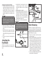
Blade Balancing
All blades are grouped by weight. Because nat-
ural woods vary in density, the fan may wobble
even though the blades are weight matched. The
following procedure should correct most fan
wobble. Check after each step.
1. Check that all blade and blade bracket
screws are secure.
2. Most fan wobble problems are caused when
blade levels are unequal. Check this level by
selecting a point on the ceiling above the tip
of one of the blades. Measure from a point
on the center of each blade to the point on the
ceiling. Measure this distance as shown in
Figure 15. Rotate the fan until the next blade
is positioned for measurement. Repeat for
each blade. Measurement deviations should
within 1/8”. Run the fan for 10 minutes.
3. Use the enclosed Blade Balancing Kit if the
blade wobble is still noticeable.

Figure 15
Figure 16
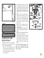
Installing the Light
Kit/Glass Bowl
CAUTION - To reduce the risk of electrical
shock, disconnect the electrical supply circuit
to the fan before installing light kit.
1. Remove two of four mounting screws and
lockwashers on the switch cup below the fan
motor assembly, loosen but do not remove
the other two mounting screws and lock-
washers (Figure 16).
TO REDUCE THE RISK OF PERSONAL INJURY,
DO NOT BEND THE BLADE HOLDERS WHILE
INSTALLING, BALANCING THE BLADES, OR
CLEANING THE FAN. DO NOT INSERT FOREIGN
OBJECTS BETWEEN ROTATING BLADES.
WAIT FOR FAN TO STOP BEFORE REVERSING
THE DIRECTION OF BLADE ROTATION.
2. Connect the blue and white wires exiting
the switch cup below the fan motor assem-
bly with the black and white wires from the
light kit assembly by connecting the polar-
ized plugs (blue to black; white to white).
Carefully push all wires back into the switch
cup.
3. Align the two key slots in the light kit as-
sembly with the two mounting screws and
lockwashers on the switch cup that were
loosened in step 1, place the light kit assem-
bly over the two screws, turn the light kit
assembly clockwise until it locks, tighten
the two screws.
4. Re-install the two mounting screws and
lockwashers that were removed in step 1
and tighten rmly.
5. Remove the nial, hex nut and rubber wash-
er from the threaded pipe of the light kit as-
sembly.
6. With power off, install the light bulbs (Max.
14w) into the sockets (Figure 16).
7. Position the glass bowl over the threaded
pipe of the light kit assembly, re-install the
rubber washer and hex nut that were pre-
viously removed to secure the glass bowl
properly. Re-install the nial and nger
tighten.
DO NOT OVERTIGHTEN THE HEX NUT
AND FINIAL, OVERTIGHTENING THE
HEX NUT OR FINIAL MAY CAUSE THE
GLASS TO BREAK.
9.
Hex Nut

Figure 17
Figure 18
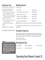
Remote Control - Your fan is equipped with a
remote control to operate the speed and lights of
your new ceiling fan. For more information on
how to install the remote control see the remote
control instruction included along with the re-
mote control components.
Speed settings for warm or cool weather depend
on factors such as the room size, ceiling height,
number of fans and so on.
The fan shipped from the factory with the re-
versing switch positioned to circulate down-
ward. If airow is desired in opposite direction,
turn your fan off and wait for the blades to stop
turning, then slide the reversing switch (located
at the top of the motor housing, refer to gure
7 on page 4) to opposite position, and turn fan
on again. The fan blades will turn in opposite
direction and reverse airow.
Speed - The remote features Low, Med, Hi and
Off buttons to select the desired speed of opera-
tion and turn the fan On or Off.
Lights - To control the light kit, the remote fea-
tures a light button.
10. Operating Your Fan
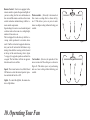
Warm weather - (Forward) A downward air
ow creates a cooling effect as shown in Fig-
ure 17. This allows you to set your air condi-
tioner on a higher setting without affecting your
comfort.
Cool weather - (Reverse) An upward air ow
moves warm air off the ceiling are as shown in
Figure 18. This allows you to set your heating
unit on a lower setting without affecting your
comfort.

Operating Your Remote Control 11.
Setting the Code
This unit has 16 different code combinations. To
set the code, perform the following steps:
A. Setting the code on the transmitter:
a. Remove the battery cover. Press rmly
below arrow and slide battery cover off.
b. Slide code switches to your choice of up
or down position. (Factory setting is all up).
B. Setting the code on the receiver.
a. Slide code switches to the same position
as set on your transmitter.
b. Replace battery cover on transmitter.
CAUTION:
Ceiling angle shall not exceed 30 degrees.
Controller Models: UC7067RK or FAN-18R Transmitter Operation
NOTE: This remote is equipped with 16 code combinations. To prevent possible interference
from or to other remote units such as garage door openers, car alarm or security system, simply
change the combination code but be sure that the code on both the hand held transmitter and
receiver in the fan are matched.
Install a 9 volt battery (not included).
Operating the Fan:
Hi Key - High Speed Med Key - Medium Speed Low Key - Low Speed
Off Key - Power Off Light Key - Light On/Off
Installing Receiver
A. Wire Connection:
Fan Green Wire ............................................................... Bare Supply Wire
Black (Or Red) Receiver Wire (AC IN L) ...................... Black Supply Wire
White Receiver Wire (AC IN N) ..................................... White Supply Wire
White Receiver Wire (TO MOTOR N) ........................... White Fan Wire
Black Receiver Wire (TO MOTOR L) ............................ Black Fan Wire
Blue Receiver Wire (FOR LIGHT) ................................. Blue Light Wire
NOTE: If other fan wires are a different color, have this unit installed by a licensed electrician.
B. Lay the black (or Brown) antenna wire on top of the receiver, and slide the receiver into the
mounting bracket.
TO REDUCE THE RISK OF FIRE OR ELECTRIC
SHOCK, REMEMBER TO DISCONNECT THE POW-
ER. THE ELECTRICAL WIRE MUST MEET ALL
LOCAL AND NATIONAL ELECTRICAL CODES RE-
QUIREMENTS. ELECTRICAL SOURCE AND FANS
MUST BE 110/120 VOLT, 60 HZ . MAXIMUM FAN MO-
TOR AMPS: 1.0. MAXIMUM TUNGSTEN 300 WATTS,
OR MAXIMUM BALLAST 300VA.

12. Care of Your Fan and Troubleshooting
Care of Your Fan
Here are some suggestions to help you
maintain your fan.
1. Because of the fan’s natural movement,
some connections may become loose.
Check the support connections, brackets,
and blade attachments twice a year. Make
sure they are secure. (It is not necessary to
remove fan from ceiling.)
2. Clean your fan periodically to help maintain
its new appearance over the years. Do not
use water when cleaning, this could damage
the motor, or the wood or possibly cause
an electrical shock. Use only a soft brush
or lint-free cloth to avoid scratching the
nish. The plating is sealed with a lacquer
to minimize discoloration or tarnishing.
Warning - Make sure the power is off
before cleaning your fan.
3. You can apply a light coat of furniture pol-
ish to the wood for additional protection
and enhanced beauty. Cover small scratches
with a light application of shoe polish.
4. There is no need to oil your fan.
The motor has permanently lubricated
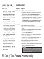
sealed ball bearings. MAKE SURE THE POWER IS OFF AT THE ELECTRICAL PANEL BOX BE-
FORE YOU ATTEMPT TO MAKE ANY REPAIRS. REFER TO THE SECTION,
“MAKING ELECTRICAL CONNECTIONS.”
Fan will not start
Fan sounds noisy
1. Check main and branch circuit fuses or breakers
2. Check line wire connections to the fan and switch wire connections in
the switch housing. CAUTION: Make sure main power is off.
3. Check batteries in the transmitter. Does the red LED light come on? Are
you standing close enough to the fan? (Normal range is 10-20 feet.) Are
the dip switch settings the same on the transmitter (hand unit) and re-
ceiver? REMEMBER TO TURN OFF POWER SUPPLY BEFORE
CHECKING THE DIP SWITCH SETTINGS IN RECEIVER.
1. Make sure all motor housing screws are snug.
2. Make sure the screws that attach the fan blade bracket to the motor hub
are tight.
3. Make sure wire nut connections are not rattling against each other or
the interior wall of the switch housing.
CAUTION: Make sure power is off.
4. Allow a 24-hour “breaking in” period. Most noises associated with a
new fan disappear during this time.
5. If using the Ceiling Fan light kit, make sure the screws securing the
glassware are tight. Check that the light bulb is also secure.
6. Make sure the canopy is a short distance from the ceiling.
It should not touch the ceiling.
7. Make sure your outlet box is secure and rubber isolator pads were used
between the mounting bracket and outlet box.
Troubleshooting
Problem Solution

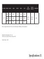
Specications 13.
FAN SIZE SPEED VOLTS AMPS WATTS RPM CFM NET
WEIGHT
GROSS
WEIGHT CUBE FEET
52”
Low 120 0.29 10 60 1932
21.8
Lbs
24.3
Lbs 1.89Med 120 0.43 27 109 3515
High 120 0.56 66 175 5510
These are approximate measures. They do not include Amps and Wattage used by the light kit.
Distributed by Home Depot U.S.A., Inc.
2455 Paces Ferry Rd. N.W. Atlanta, Georgia 30339
Vendor Number: 11688

14. Warranty Information
Hampton Bay Lifetime Limited Warranty
Lifetime Warranty on Motor
Hampton Bay warrants the fan motor to be free from defects in workmanship and material present at
time of shipment from the factory for a lifetime after the date of purchase by the original purchaser.
Hampton Bay also warrants that all other fan parts, excluding any glass or acrylic blades, to be free
from defects in workmanship and material at the time of shipment from the factory for a period of
one year after the date of purchase by the original purchaser. We agree to correct such defects with-
out charge or at our option replace with a comparable or superior model if the product is returned to
Hampton Bay. To obtain warranty service, you must present a copy of the receipt as proof of pur-
chase. All costs of removing and reinstalling the product are your responsibility. Damage to any part
such as by accident or misuse or improper installation or by afxing any accessories, is not covered
by this warranty. Because of varying climatic conditions, this warranty does not cover any changes
in plated nishes, including rusting, pitting, corroding, tarnishing or peeling. Brass nishes of this
type give their longest useful life when protected from varying weather conditions. A certain amount
of “wobble” is normal and should not be considered a defect. Servicing performed by unauthorized
persons shall render the warranty invalid. There is no other express warranty. Hampton Bay hereby
disclaims any and all warranties, including but not limited to, those of merchantability and tness
for a particular purpose to the extent permitted by law. The duration of any implied warranty which
cannot be disclaimed is limited to the time period as specied in the express warranty. Some states
do not allow limitation on how long an implied warranty lasts, so the above limitation may not apply
to you. Hampton Bay shall not be liable for incidental, consequential, or special damages arising out
of or in connection with product use or performance except as may otherwise be accorded by law.
Some states do not allow the exclusion of incidental or consequential damages, so the above exclu-
sion or limitation may not apply to you. This warranty gives specic legal rights, and you may also
have other rights which vary from state to state. This warranty supersedes all prior warranties. Ship-
ping costs for any return of product as part of a claim on the warranty must be paid by the customer.
IMPORTANT NOTE:
To ensure warranty service, if ever
necessary, please register your fan at:
gpwarranty.com
You must present a copy of the original
purchase receipt to obtain warranty service.
G.P. WARRANTY SERVICE CENTER, INC.
WARRANTY SECTION
1951 N.W. 22nd STREET
FORT LAUDERDALE, FLORIDA 33311
Attach receipt here for
easy location.

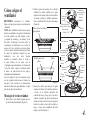
Clarington de 52”
Ventilador de techo de Hampton Bay
Función de reversa de 3 velocidades para
confort y ahorro durante todo el año
Inclinación de aspa más pronunciada
para obtener un mayor ujo de aire
Instalación de montaje triple
Control remoto portátil
¿PREGUNTAS, PROBLEMAS O PIEZAS FALTANTES?
Antes de volver a tu tienda local de The Home Depot, llama a nuestro
Equipo de Servicio al Cliente al 1-877-527-0313 o visita www.homedepot.com.
Por favor usa como referencia el Nº de SKU (503 837 caoba dorado)
o UPC (082392 613938R caoba dorado).
Gracias por comprar este ventilador de techo de
Hampton Bay. Este producto se ha fabricado con las
normas de seguridad y calidad más altas. El acabado
de este ventilador es resistente a la intemperie, pero
con el tiempo, exhibirá un desgaste y decoloración
naturales.
Normas de seguridad ................................1
Cómo desempacar el ventilador ...............2
Cómo instalar el ventilador ......................3
Cómo operar el ventilador .......................10
Cómo manejar el control remoto .............11
Cuidado del ventilador .............................12
Solución de problemas .............................. 12
Especicaciones ......................................... 13
Información de la garantía .......................14
Índice
No. de Modelo UL 52-BGM

1. Para disminuir el riesgo de descarga eléctrica, asegúrate de que
la electricidad ha sido apagada en el cortacircuitos o la caja de
fusibles antes de comenzar la instalación.
2. Todo el cableado debe cumplir con el Código Nacional de
Electricidad ANSI/NFPA 70-1999 y con los códigos locales
de electricidad. La instalación eléctrica debe ser hecha por un
electricista certicado y calicado.
3. ADVERTENCIA:Para disminuir el riesgo de incendio o
descarga eléctrica este ventilador sólo debe ser usado con
un control identicado con el N.o de pieza UC7067RK,
fabricada por Rhine Electronic Co., Ltd. o la pieza Nº: FAN-
18R fabricado por Chia Wei Electric Co., Ltd.
4. PRECAUCIÓN: Para reducir el riesgo de lesiones físicas, usa
sólo los tornillos provistos con la caja eléctrica.
5. La caja eléctrica y estructura de soporte deben montarse
de forma segura y tener capacidad para sostener de manera
conable un mínimo de 35 libras. Usa solamente cajas eléctricas
aprobadas por UL marcadas como “PARA SOPORTE DE
VENTILADOR”.
6. El ventilador debe ir montado con un mínimo de 7 pies de
separación entre el borde trasero de las aspas y el piso.
7. No operar el interruptor de reversa mientras las aspas del ventilador
estén en movimiento. El ventilador debe estar apagado y las aspas
detenidas antes de invertir la dirección del movimiento.
8. Evita colocar objetos en la trayectoria de las aspas.
9. Para evitar lesiones, o daños al ventilador y otros objetos; ten
cuidado al trabajar cerca del ventilador o al limpiarlo.
10. No usar agua o detergentes para limpiar el ventilador o las
aspas. En general a la hora de limpiar, bastará con usar un paño
seco o ligeramente humedecido.
11. Después de concluir con las conexiones eléctricas, debes
voltear los conductores empalmados hacia arriba y empujarlos
con cuidado hacia dentro de la caja eléctrica. Los cables deben
estar separados, con el cable a tierra y el conductor a tierra del
equipo hacia uno de los lados de la caja eléctrica.
12. Los diagramas eléctricos son sólo una referencia. Los kits de
luces no empaquetados con el ventilador deben estar aprobados
por UL y marcados como apropiados para ser usados con el
modelo de ventilador a instalar. Los interruptores deberán
estar clasicados por el UL como de Uso General. Consulta
las instrucciones adjuntas a los kits de luces e interruptores
para obtener información sobre el montaje adecuado.
13. Todos los tornillos colocados se deben vericar y ajustar donde
sea necesario antes de la instalación
1. Normas de seguridad
LEE LAS INSTRUCCIONES Y GUÁRDALAS
PARA REDUCIR EL RIESGO DE INCENDIO, DESCARGA ELÉCTRICA O LESIONES
PERSONALES, MONTA EL VENTILADOR SOBRE UNA CAJA ELÉCTRICA MARCADA COMO
“APROBADA COMO SOPORTE DE VENTILADOR” Y USA TORNILLOS DE MONTAJE QUE
VIENEN CON LA MISMA.
PARA REDUCIR EL RIESGO DE LESIONES PERSONALES, NO DOBLAR LOS BRAZOS
DE LAS ASPAS (TAMBIÉN LLAMADOS “REBORDES”) DURANTE O DESPUÉS DE LA
INSTALACIÓN. EVITA COLOCAR OBJETOS EN LA TRAYECTORIA DE LAS ASPAS.
PARA REDUCIR EL RIESGO DE DESCARGA ESTE VENTILADOR DEBE SER INSTALADO
CON UN CONTROL/INTERRUPTOR DE AISLAMIENTO DE MONTAJE EN PARED.

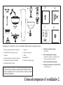
a. Herrajes de montaje de aspas
(15 tornillos)
b. Kit de compensación y herrajes
(1 pasador de soporte, 1 pasador de cierre,
3 conectores plásticos de cable)
c. Kit de compensación de las aspas
d. Herrajes para montaje “Cerca del Techo”
(1 junta de goma)
7. Aspas (5)
8. Soportes del aspa (5)
9. Vidrio
10. Bombillas (2)
11. Unidad de mano/Receptor
1. Placa de montaje (dentro de la cubierta)
2. Ensamblado de tubo bajante y bola
3. Cubierta
4. Cubierta decorativa del collarín del motor
5. Ensamblado del motor del ventilador
6. Ensamblado del kit de luces
Cómo desempacar el ventilador 2.
IMPORTANTE: ESTE PRODUCTO Y/O SUS COMPONENTES ESTÁN PRO-
TEGIDOS POR UNA O MÁS DE LAS SIGUIENTES PATENTES DE EE.UU.:
5,947,436; 5,988,580; 5,971,573; 6,010,306; 6,039,541; 6,046,416 y OTRAS
PATENTES PENDIENTES.
Desempaca tu ventilador y revisa el contenido. Deberá tener las siguientes piezas:
d
b
c
a

3. Cómo instalar el ventilador
Herramientas necesarias
Destornillador Phillips, destornillador plano,
llave ajustable, escalera de tijera y cortacables.
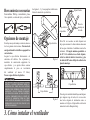
Opciones de montaje
Si no hay una caja de montaje existente, entonces
lee las siguientes instrucciones. Desconecta la
energía retirando los fusibles o apagando los
cortacircuitos.
Asegura la caja eléctrica directamente a la
estructura del edicio. Usa sujetadores y
materiales de construcción apropiados. La
caja eléctrica y su soporte deben sostener
completamente el peso en movimiento
del ventilador (al menos 35 libras).
No uses cajas eléctricas de plástico.
Las guras 1, 2 y 3 son ejemplos de diferentes
formas de montar la caja eléctrica.
Outlet Box
Nota: Tal vez necesites un tubo bajante más
largo para mantener la altura mínima adecuada
de las aspas al instalar el ventilador en un techo
inclinado. El ángulo máximo permitido es
de 30º. Si la cubierta toca el tubo bajante,
retira la cubierta inferior decorativa y gira
la cubierta 180º antes de jar la cubierta a la
placa de montaje.
Outlet Box
Para colgar tu ventilador donde haya una lámpara
pero ninguna viga de techo, tal vez necesites
una barra colgante de instalación como se
muestra en la Figura 4 (disponible en la tienda
minorista local de Hampton Bay).
Figura 1
Figura 2
Figura 4
Figura 3
PARA REDUCIR EL RIESGO DE INCENDIO, DESCARGA
ELÉCTRICA O LESIONES PERSONALES, MONTA EL
VENTILADOR SÓLO SOBRE UNA CAJA ELÉCTRICA
MARCADA COMO “APROBADA COMO SOPORTE DE
VENTILADOR” Y USA LOS TORNILLOS DE MONTAJE
QUE VIENEN CON LA MISMA. LAS CAJAS ELÉCTRICAS
UTILIZADAS COMÚNMENTE PARA EL SOPORTE DE
ARTÍCULOS DE ILUMINACIÓN PUEDEN NO SERVIR
COMO SOPORTE DE VENTILADOR, Y TAL VEZ DEBAN
REEMPLAZARSE. EN CASO DE DUDA, CONSULTA A UN
ELECTRICISTA CALIFICADO.
Caja eléctrica
Caja eléctrica
empotrada
Soporte fuerte
Placa de
montaje en
el techo
Caja eléctrica
Caja eléctrica

2. Retira la placa de montaje de la cubierta
aojando los cuatro tornillos de la parte
superior de la misma. Quita los dos tornillos
sin ranura y aoja los tornillos ranurados.
Esto te permitirá retirar la placa de montaje
(Figura 6).
4.
Cómo colgar el
ventilador
RECUERDA desconectar la corriente.
Sigue estos pasos para colgar correctamente tu
ventilador.
NOTA: Este ventilador de techo viene con dos
tipos de ensamblados de soporte; la instalación
de techo estándar con tubo bajante y bola,
y casquillo de montaje; y el montaje “cerca
del techo”. El montaje “cerca del techo” se
recomienda en habitaciones con techos de
menos de 8 pies de altura o en áreas donde
se desee espacio adicional desde el piso hasta
las aspas de ventilador. Cuando uses una
instalación con un tubo bajante
estándar, la distancia desde el techo a
la parte inferior de las aspas será de
15 pulgadas aproximadamente. La instalación
“cerca del techo” reduce la distancia desde
el techo a la parte inferior de las aspas a
8 pulgadas aproximadamente.
Una vez elegido el tipo de instalación, sigue
con las siguientes instrucciones. Cuando sea
necesario, cada sección de las instrucciones
indicará los diferentes procedimientos a seguir
para los dos tipos de instalación.
Montaje de techo estándar
1. Retira el aro en la cubierta, girando el aro a
la derecha hasta destrabarlo (Figura 5).
Figura 5
Figura 6
Figura 7
3. Inserta los cables que salen por la parte
superior del motor del ventilador, primero,
a través de la cubierta decorativa del
collarín del motor y luego, por el aro de la
cubierta. Asegúrate de que las aberturas en
forma de ranura estén en la parte superior.
Inserta los cables a través de la cubierta y
luego a través del ensamblado del tubo
bajante y la bola (Figura 7).
Quitar
Aójalo pero no lo
quites
Gira el aro en la cubierta
para quitarla
Cubierta
Aro de la
cubierta
Apretar los
tornillos
Cubierta del
collarín del
motor
Pasador
de soporte
Cables del motor
Ensamblado de
tubo bajante/bola Posición de
cierre del
pasador
Pasador de
cierre
Caja eléctrica
aprobada
por UL
Desliza la palaca de
montaje sobre la cabeza
de los tornillos
Cable de 120 V
Tornillos de
montaje (provistos
con la caja
eléctrica)
Gancho
Placa de
montaje de
techo
Collarín
del motor
Interruptor
de reversa

Montaje “Cerca del Techo”
1. Retira el aro en la cubierta, girando el aro a la
derecha hasta destrabarlo (Figura 5).
2. Retira el soporte de montaje de la cubierta
aojando los cuatro tornillos en la parte
superior de la cubierta. Quita los dos tornillos
sin ranura y aoja los tornillos ranurados.
Esto te permitirá retirar el soporte de montaje
(Figura 6).
3. Retira la cubierta inferior decorativa de la
cubierta oprimiendo los tres pernos (Figura 8).
4. Retira tres de los seis tornillos y arandelas de
seguridad (alternados) que sujetan el collarín
del motor a la parte superior de la carcasa del
motor (Figura 9).
5. Coloca la junta de goma sobre los otros tres
tornillos, inserta los cables que salen por la parte
superior del motor del ventilador a través del
aro de la cubierta (asegúrate de que las aberturas
en forma de ranura estén en la parte superior),
luego procede a colocar la cubierta de techo
sobre el collarín en la parte superior del motor
(Figura 10).
Figura 8
5.
4. Aoja, sin quitarlo, el tornillo en el collarín
ubicado en la parte superior de la carcasa del
motor.
5. Alinea los oricios en la parte inferior
del tubo bajante con los oricios en el
collarín de la parte superior de la carcasa
de motor (Figura 7). Inserta con cuidado
el pasador de soporte a través de los
oricios del collarín y del tubo bajante.
Ten cuidado de no apretarlo contra el
cableado dentro del tubo bajante. Inserta el
pasador de cierre en el oricio cercano al
extremo del pasador de soporte hasta que
quede encajado en su posición como se
muestra en el círculo de la Figura 7.
6. Vuelve a ajustar los tornillos del collarín
en la parte superior de la carcasa del motor
(Figura 8).
7. Asegúrate de que el ojal esté instalado
correctamente en la cubierta del collarín,
luego desliza la cubierta del collarín por el
tubo bajante hasta que quede en la carcasa
del motor. Asegúrate de que la cubierta y la
cubierta del collarín tengan la orientación
apropiada.
8. Sigue con la sección "Cómo instalar el
ventilador".
Figura 9
Figura 10
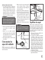
6. Alinea los oricios de montaje con los oricios
del motor y asegura con los tres tornillos y
arandelas de seguridad retiradas en el paso 4
(Figura 10).
7. Asegúrate de ajustar bien los tornillos de
montaje.
SI NO COLOCAS CORRECTAMENTE LOS TORNILLOS
SEGÚN LO INDICADO EN EL PASO 6 SE PUEDEN AFLOJAR
Y POSIBLEMENTE SE CAIGA EL VENTILADOR.
SI NO COLOCAS CORRECTAMENTE LOS TORNILLOS
SEGÚN LO INDICADO EN EL PASO 7 SE PUEDEN AFLOJAR
Y POSIBLEMENTE SE CAIGA EL VENTILADOR.
Collarín del
motor
Cubierta
de techo Aro de
cubierta
Collarín
Tornillo y
arandela de
seguridad (3
tornillos)
Tornillo y
arandela de
seguridad (3 de 6
tornillos)
Junta de
goma

6.
Cómo instalar el
ventilador en
la caja eléctrica
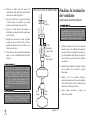
1. Pasa los cables de 120 voltios a través del
oricio central en el soporte de montaje de
techo como lo muestra la Figura 7.
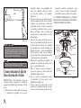
2. Instala la placa de montaje del techo en la
caja eléctrica deslizando la placa de montaje
sobre los dos tornillos provistos con la caja
eléctrica (Figura 11). Cuando uses el montaje
cerca del techo, es importante que el soporte
de montaje esté nivelado. Si es necesario, usa
arandelas niveladoras (no incluidas) entre la
placa de montaje y la caja eléctrica. Nota
que el lado plano del soporte de montaje está
hacia la caja eléctrica (Figura 11).
3. Ajusta rmemente los dos tornillos de
montaje.
4. Para mayor seguridad, a través de las ranuras
exteriores de la placa de montaje, atornilla
en la viga de madera dos tornillos para
madera con arandelas planas (no incluidas).
Nota: Deja un tornillo para madera ojo
para jar el cable seguridad del motor.
5. Con cuidado alza el ensamblado del ventilador
hasta la placa de montaje. Si usas el montaje
cerca del techo, cuelga el ventilador del
Figura 11
Cómo hacer las
conexiones eléctricas
RECUERDA desconectar la electricidad. Si
crees que no tienes suciente experiencia o
conocimientos en cableado eléctrico, contrata a
un electricista con licencia para que instale el
ventilador.
Nota: Instala el receptor antes de conectar el
ventilador, consulta Cómo manejar el control
remoto en la página 10 para más detalles o sigue
las instrucciones que vienen con el receptor.
Sigue estos pasos para conectar tu ventilador a tu
circuito doméstico. Usa las tuercas de conexión
de cables que vienen con tu ventilador. Asegura
los conectores con cinta aislante. Asegúrate de
que no existan conexiones o cables sueltos.
1. Conecta el conductor a tierra del cable de
120 voltios (puede ser un cable desnudo o
un cable con aislante verde) al (los) cable(s)
terminal(es) a tierra verde(s) del ventilador
(Figura 12). Conecta el cable blanco del
motor del ventilador al cable blanco de
suministro (neutro) usando una tuerca de
cable (Figura 12).
2. Conecta el cable blanco del motor del
ventilador al cable blanco del receptor,
usando una tuerca de cable (Figura 12).
3. Conecta el cable negro del motor del
ventilador al cable negro del receptor usando
una tuerca de cable (Figura 12).
gancho suministrado usando uno de los
oricios en el borde exterior de la cubierta
de techo (Figura 11). Si usas el montaje
estándar, asienta la bola de soporte en la
placa del soporte de montaje. Asegúrate de
que la pestaña sobre el casquillo de soporte
de montaje encaje bien dentro de la ranura
de la bola de soporte.
Montaje cerca
del techo
Montaje estándar
CUANDO MONTES EL VENTILADOR EN UN TECHO
INCLINADO, DEBES USAR EL MÉTODO DE MONTAJE CON
TUBO BAJANTE Y BOLA ESTÁNDAR. ASEGÚRATE DE QUE
LAS RANURAS DEL SOPORTE DE MONTAJE ESTÉN EN EL
LADO INFERIOR DESLIZANDO EL SOPORTE DE MONTAJE
DESDE ARRIBA HACIA ABAJO.
CUANDO USES EL MONTAJE DE TUBO BAJANTE Y
BOLA ESTÁNDAR, LA PESTAÑA EN EL ARO EN LA PARTE
INFERIOR DEL SOPORTE DE MONTAJE DEBE ENCAJAR
EN LA RANURA DE LA BOLA DE SOPORTE. SI NO ENCAJA
CORRECTAMENTE, SE PUEDE DAÑAR EL CABLEADO.
EL GANCHO COMO SE MUESTRA EN LA FIGURA 11
SOLAMENTE ES PARA SOSTENER EL VENTILADOR
MIENTRAS SE CONECTAN LOS CABLES. SI NO SE CUELGA
COMO SE MUESTRA EN LA FIGURA 11, PUEDE ROMPERSE
EL GANCHO, Y EL VENTILADOR SE CAERÁ. EL GANCHO
DEBE PASAR DE ADENTRO HACIA FUERA DE LA CUBIERTA.

7.
CADA TUERCA DEL CABLE (CONECTOR DE CABLE)
PROVISTA CON ESTE VENTILADOR ESTÁ DISEÑADA
PARA ACEPTAR CABLES DOMÉSTICOS DE MÁXIMO UN
CALIBRE 12 Y DOS CABLES DEL VENTILADOR. SI TIENES
UN CABLEADO DOMÉSTICO DE CALIBRE SUPERIOR A
12, O MÁS DE UN CABLE DOMÉSTICO PARA CONECTAR
EL CABLEADO DEL VENTILADOR, CONSULTA A UN
ELECTRICISTA PARA EL TAMAÑO ADECUADO DE TUERCAS
DE CABLE.
Figura 12
LOS DIAGRAMAS ELÉCTRICOS SON SÓLO UNA
REFERENCIA. EL USO OPCIONAL DE KITS DE LUCES DEBE
ESTAR APROBADO POR UL Y ESTARÁ MARCADO COMO
ADECUADO PARA SER USADO EN ESTE VENTILADOR.
4. Conecta el cable azul del motor del
ventilador al cable azul del receptor usando
una tuerca de cable (Figura 8).
5. Conecta el cable rojo (o negro) del receptor
al cable negro de suministro de energía
(positivo) usando una tuerca de cable.
6. Conecta el cable blanco del receptor al
cable blanco de energía (neutro) usando una
tuerca de cable.
7. Después de conectar los cables, sepáralos
de manera que los cables verde y blanco
queden de un lado de la caja eléctrica y el
cable negro del otro.
8. Gira las tuercas de conexión del cable hacia
arriba y coloca el cableado dentro de la caja
eléctrica.
Finalizar la instalación
del ventilador
MONTAJE DE TECHO ESTÁNDAR
1. Alinea las ranuras de cierre de la cubierta
de techo con los dos tornillos de la placa de
montaje. Alza para enganchar las ranuras y
gira de izquierda a derecha para asegurar en
su sitio. Ajusta con rmeza los dos tornillos
de montaje.
2. Instala los dos tornillos de montaje restantes
en los oricios de la cubierta y aprieta
rmemente.
3. Instala el aro de cubierta decorativa
alineando las ranuras del aro con los tornillos
en la cubierta. Rota el aro en sentido de las
manecillas del reloj para jarlo.
4. Ahora puedes proceder a montar las
aspas del ventilador.
CUANDO USES EL MONTAJE DE TUBO BAJANTE Y
BOLA ESTÁNDAR, LA PESTAÑA EN EL ARO EN LA PARTE
INFERIOR DEL SOPORTE DE MONTAJE DEBE ENCAJAR
EN LA RANURA DE LA BOLA DE SOPORTE. SI NO ENCAJA
CORRECTAMENTE, SE PUEDE DAÑAR EL CABLEADO.
CIRCUITO DE SUMINISTRO
Caja
eléctrica
Negro
Azul
Blanco Blanco
Negro
Rojo
(o negro)
Blanco
Cable
terminal a
tierra verde
Receptor
Tierra al
tubo bajante
Blanco
Blanco
Azul
Negro

8.
MONTAJE CERCA DEL TECHO
1. Con cuidado desengancha el ventilador del
soporte de montaje y alinea las ranuras de
cierre de la cubierta del techo con los dos
tornillos en el soporte de montaje. Alza para
enganchar las ranuras y gira de izquierda a
derecha para asegurar en su sitio. Ajusta con
rmeza los dos tornillos de montaje.
2. Instala los dos tornillos de montaje restantes
en los oricios de la cubierta y aprieta
rmemente.
3. Instala el aro de cubierta decorativa
alineando las ranuras del aro con los tornillos
en la cubierta. Rota el aro en sentido de las
manecillas del reloj para jarlo.
4. Ahora puedes proceder a montar las aspas
del ventilador.
Cómo montar las
aspas del ventilador
NOTA: Las aspas de tu ventilador son
reversibles. Elige el acabado del aspa que mejor
resalte tu decoración.
LAS RANURAS DE CIERRE DE LA CUBIERTA DEL TECHO
SÓLO SIRVEN DE AYUDA DURANTE LA INSTALACIÓN.
NO DEJES SIN SUPERVISIÓN EL ENSAMBLADO DEL
VENTILADOR HASTA QUE LOS CUATRO TORNILLOS DE LA
CUBIERTA SE FIJEN Y AJUSTEN FIRMEMENTE.
SI NO INSTALAS CORRECTAMENTE LAS ASPAS EN SUS
SOPORTES Y ACTIVAS LOS MECANISMOS DE CIERRE,
SE PUEDEN AFLOJAR LAS ASTAS Y POSIBLEMENTE SE
CAIGAN.
1. Monta el soporte de aspa usando tornillos
como lo muestra la Figura 14. Primero
coloca un tornillo en el soporte. Repite para
los otros dos tornillos.
2. Aprieta todos los tornillos de manera rme.
3. Ajusta el brazo del aspa al motor insertando
el poste de alineación dentro de la ranura
de la parte inferior del motor y aprieta los
tornillos del soporte del aspa. Por favor,
ten en cuenta que los tornillos del soporte
de aspa están previamente instalados en el
soporte del aspa (Figura 14).
4. Repite los pasos 1-3 para las aspas restantes.
Figura 13
Figura 14
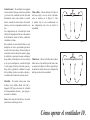
Equilibrar las aspas
Todas las aspas se agrupan por peso. Como las
maderas naturales varían en densidad, el ventilador
puede oscilar aunque las aspas tengan el mismo
peso. El siguiente procedimiento corregirá en
gran medida la oscilación del ventilador. Verica
después de cada paso.
1. Verica que todas las aspas y tornillos de los
soportes de aspas estén seguros.
2. La mayoría de los problemas de oscilación
del ventilador se deben a que las aspas no
están a un mismo nivel. Verica este nivel
seleccionando un punto en el techo sobre
la punta de una de las aspas. Mide desde un
punto en el centro de cada aspa a un punto en
el techo. Mide esta distancia como se muestra
en la Figura 15. Rota el ventilador hasta que se
posicione la siguiente aspa para su medición.
Repite para cada aspa. Las desviaciones de la
medición deben estar dentro de 1/8”. Enciende
el ventilador por 10 minutos.
3. Usa el kit de compensación de aspas adjunto si
sigues notando oscilación.
Tornillos
Aspa
Soporte de aspa
Tornillos
Ensamblado
de aspa/soporte
de aspa
Poste de
alineación
Ranura

Figura 15
Figura 16
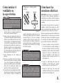
Cómo instalar el kit de
luces/tazón de vidrio
PRECAUCIÓN – Para disminuir el riesgo de
descarga eléctrica, desconecta el circuito de
energía del ventilador antes de instalar el kit de
luces.
1. Retira dos de los cuatro tornillos de montaje
y arandelas de seguridad en la caja del
PARA REDUCIR EL RIESGO DE LESIONES PERSONALES,
NO DOBLAR LOS SOPORTES DE LAS ASPAS DURANTE LA
INSTALACIÓN, COMPENSACIÓN DE LAS ASPAS O LIMPIEZA
DEL VENTILADOR. NO INSERTES OBJETOS EXTRAÑOS
ENTRE LAS ASPAS EN FUNCIONAMIENTO.
ESPERA A QUE SE DETENGA EL VENTILADOR ANTES DE
INVERTIR LA DIRECCIÓN DE GIRO DE LAS ASPAS.
interruptor debajo del ensamblado del
motor del ventilador; aoja, sin quitar,
los otros dos tornillos y las arandelas
(Figura 16).
2. Conecta el cable azul y el cable blanco que
salen del adaptador del kit de luces, debajo
del motor, con el cable negro y blanco del
ensamblado del kit de luces, conectando
los enchufes polarizados (azul con negro,
blanco con blanco). Vuelve a colocar con
cuidado todos los cables dentro de la caja
del interruptor.
3. Alinea las dos ranuras en forma de ojo de
llave en el ensamblado del kit de luces con
los dos tornillos de montaje y las arandelas
de seguridad en la caja del interruptor que
aojaste en el paso 1, coloca el ensamblado
del kit de luces sobre los dos tornillos,
gíralo de izquierda a derecha hasta trabarlo
y después aprieta los dos tornillos
4. Reinstala los dos tornillos de montaje y las
arandelas de seguridad que retiraste en el
paso 1 y aprieta rmemente.
5. Retira el remate, la tuerca hexagonal y
la junta de goma en el tubo roscado del
ensamblado del kit de luces.
6. Con la corriente desconectada, instala
las bombillas (14 vatios máx.) en los
portalámparas (Figura 16).
7. Coloca el tazón de vidrio sobre el tubo
roscado del ensamblado del kit de luces,
vuelve a colocar la junta de goma y la tuerca
Punto en el
techo
Caja del interruptor
Blanco
Negro
Azul
Ensamblado del kit
de luces
Tornillos de
montaje y
arandelas de
seguridad
Tubo roscado
Bombillas
(incluidas)
Bombillas
(incluidas)
Vidrio
Arandela de goma
Tuerca
9.
hexagonal retiradas previamente, para
sujetar el tazón de vidrio correctamente.
Reinstala el remate y aprieta con los dedos
NO APRIETES DEMASIADO LA TUERCA
HEXAGONAL Y EL REMATE, AL HACERLO
PODRÍAS ROMPER EL VIDRIO.

Figura 17
Figura 18
Control remoto - Tu ventilador está equipado
con un control remoto que controla la velocidad
y las luces de tu ventilador de techo. Para más
información sobre cómo instalar el control
remoto, consulta las instrucciones del control
remoto y revisa los componentes incluidos con
éste.
Las conguraciones de velocidad para clima
cálido o frío dependen de factores como tamaño
de la habitación, altura del techo, cantidad de
ventiladores y demás.
Este ventilador se envía desde la fábrica con el
interruptor de reversa posicionado para hacer
circular el aire hacia abajo. Si deseas dirigir la
corriente de aire en la dirección contraria, apaga
el ventilador y espera que las aspas se detengan,
luego desliza el interruptor de reversa (ubicado
en la caja de interruptores, consulta la Figura
7 de la página 4) hacia la dirección opuesta y
luego vuelve a prender el ventilador. Las aspas
del ventilador girarán en sentido contrario y
revertirán la dirección de la corriente de aire.
Velocidad - El control remoto tiene teclas
de Bajo (Low), Medio (Med), Alto (Hi) y
Apagado (Off) para seleccionar la velocidad
de funcionamiento deseada y para apagar o
encender el ventilador.
Luces - Para controlar el kit de luces, el control
remoto tiene un botón para luces.
Cómo operar el ventilador 10.
Clima cálido - (Hacia adelante) Un ujo de
aire hacia abajo crea un efecto refrescante
como se muestra en la Figura 17. Esto
te permite jar tu aire acondicionado en
una conguración más alta sin afectar tu
comodidad.
Clima fresco - (Reversa) Un ujo de aire hacia
arriba mueve el aire cálido lejos del techo como
se muestra en la Figura 18. Esto te permite jar
tu unidad de calefacción en una conguración
más baja sin afectar tu comodidad.

11. Cómo manejar el control remoto
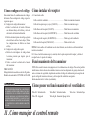
Cómo congurar el código
Esta unidad tiene 16 combinaciones de códigos
diferentes. Para congurar el código, sigue los
siguientes pasos:
A. Congurar el código del transmisor:
a. Retira la cubierta de la batería. Presiona
con rmeza debajo de la echa y retira la
cubierta de la batería deslizándola.
b. Desliza los interruptores de código según tu
elección hacia arriba o hacia abajo. (Todas
las conguraciones de fábrica son hacia
arriba).
A. Congurar el código del receptor.
a. Desliza los interruptores de código hacia
la misma posición que elegiste para el
transmisor.
b. Vuelve a colocar la cubierta de la batería
del transmisor.
PRECAUCIÓN:
El ángulo del techo no debe exceder los 30 grados.
Modelos de controlador: UC7067RK o FAN-18R
Funcionamiento del transmisor
NOTA: Este control remoto está equipado con 16 combinaciones de códigos. Para evitar posibles
interferencias desde o hacia otras unidades remotas como los abrepuertas de garajes, alarmas de
autos o sistemas de seguridad, simplemente cambia el código de combinación pero asegúrate de
que el código del transmisor de mano y del receptor del ventilador sean iguales.
Instala una batería de 9 voltios (no incluida).
Cómo poner en funcionamiento el ventilador:
Tecla Hi - Velocidad alta Tecla Med - Velocidad media Tecla Low - Velocidad baja
Tecla Off - Apagado Tecla Light - Encender/Apagar la luz
Cómo instalar el receptor
A Conexión de cable:
Cable verde del ventilador .............................................. Cable de suministro desnudo
Cable del receptor negro (o rojo) (CA EN L) ................. Cable de suministro negro
Cable blanco del receptor (CA EN N) ............................ Cable blanco de suministro
Cable blanco del receptor (AL MOTOR N) .................... Cable blanco del ventilador
Cable negro del receptor (AL MOTOR L) ...................... Cable negro del ventilador
Cable azul del receptor (PARA LUZ) ............................. Cable azul de la luz
NOTA: Si otros cables del ventilador son de color diferente, un electricista certicado deberá
instalar esta unidad.
B. Coloca el cable de antena negro (o marrón) sobre la parte superior del receptor y desliza el
receptor hasta el soporte de montaje.
PARA REDUCIR EL RIESGO DE INCENDIO O DE DESCARGA
ELÉCTRICA, RECUERDA DECONECTAR LA ELECTRICIDAD.
EL CABLEADO ELÉCTRICO DEBE CUMPLIR CON TODOS
LOS REQUISITOS DE LOS CÓDIGOS DE ELECTRICIDAD
LOCALES Y NACIONALES. LA FUENTE DE ELECTRICIDAD Y
LOS VENTILADORES DEBE SER DE 110/120 VOLTIOS Y 60HZ
MÁXIMO DE AMPERIOS DEL MOTOR DEL VENTILADOR:
1.0. TUNGSTENO DE 300 VATIOS MÁXIMO O BALASTRO
DE 300VA

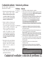
Cuidado del ventilador y solución de problemas 12.
Cuidado del ventilador
Aquí tienes algunas sugerencias para el
mantenimiento de tu ventilador.
1. Debido al movimiento natural del ventilador,
algunas conexiones pueden aojarse.
Revisa las conexiones de soporte, soportes
y accesorios de aspas dos veces al año.
Verica que estén seguros. (No es necesario
desmontar el ventilador del techo).
2. Limpia tu ventilador con frecuencia, para
que luzca como nuevo a pesar de los años.
No uses agua al limpiar, esto puede dañar
el motor o la madera, o causar descargas
eléctricas. Usa solamente un cepillo suave
o trapo sin pelusas para evitar arañar el
acabado. El revestimiento está sellado
con laca para minimizar la decoloración u
opacidad. Advertencia: Asegúrate de que
la corriente esté apagada antes de limpiar
el ventilador.
3. Puedes aplicar una na capa de pulimento
para muebles a la madera para una mayor
protección y belleza. Cubre los arañazos
pequeños con una leve aplicación de
lustrador para calzado.
4. Tu ventilador no necesita lubricación.
El motor tiene cojinetes de bola sellados
permanentemente lubricados.
ASEGÚRATE DE QUE ESTÉ DESCONECTADA LA ELECTRICIDAD EN EL PANEL DE
ELECTRICIDAD ANTES DE INTENTAR HACER REPARACIONES. CONSULTA LA SECCIÓN
“CÓMO HACER LAS CONEXIONES ELÉCTRICAS”.
El ventilador no
enciende
El ventilador hace
ruido
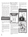
1. Verica fusibles o disyuntores principales y secundarios.
2. Verica conexiones de cables en línea al ventilador y conexiones de cables
del interruptor en la caja de interruptores. PRECAUCIÓN: Asegúrate de
que esté desactivada la electricidad principal.
3. Verica las baterías en el transmisor. ¿Se enciende la luz LED roja? ¿Estás
lo sucientemente cerca del ventilador? (El rango normal es de 10-12
pies) ¿Coinciden las conguraciones del interruptor en el transmisor
(unidad de mano) y el receptor? RECUERDA DESCONECTAR
LA ELECTRICIDAD ANTES DE VERIFICAR LAS
CONFIGURACIONES DEL INTERRUPTOR EN EL RECEPTOR.
1. Asegúrate de que los tornillos de la carcasa del motor estén ajustados.
2. Asegúrate de que los tornillos que unen el soporte de aspa al cuerpo del
motor están bien ajustados.
3. Asegúrate de que las conexiones de tuerca de cable no choquen unas con
otras o con la pared interior de la caja del interruptor.
PRECAUCIÓN: Asegúrate de que esté desconectada la electricidad.
4. Permite un período de 24 horas de “adaptación”. La mayoría de los ruidos
asociados con un nuevo ventilador desaparecen en ese período.
5. Si usas el kit de luces de ventilador de techo, asegúrate de que los tornillos
que sujetan el vidrio estén bien colocados. Verica que la bombilla de luz
esté bien asegurada.
6. Asegúrate de que la cubierta esté a corta distancia del techo.
No debe tocar el techo.
7. Asegúrate de que tu caja eléctrica esté bien segura y las almohadillas
aislantes de goma se hayan instalado entre el soporte de montaje y la caja
eléctrica.
Solución de problemas
Problema Solución

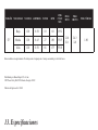
13. Especicaciones
TAMAÑO VELOCIDAD VOLTIOS AMPERIOS VATIOS RPM
PIES
CÚB. X
MIN.
PESO
NETO
PESO
BRUTO PIES CÚBICOS
52”
Baja 120 0.29 10 60 1932
21.8
Lb
24.3
Lb 1.89Media 120 0.43 27 109 3515
Alta 120 0.56 66 175 5510
Estas medidas son aproximadas. No incluyen ni el amperaje ni el vataje consumido por el kit de luces.
Distribuido por Home Depot U.S.A., Inc.
2455 Paces Ferry Rd. N.W. Atlanta, Georgia 30339
Número del proveedor: 11688

Información de la garantía 14.
Garantía limitada de por vida de Hampton Bay
Garantía de por vida para el motor
Hampton Bay garantiza de por vida, a partir de la fecha de compra por el comprador original, que el
motor del ventilador no presenta defectos de fabricación ni de material desde la fecha de salida de
la fábrica. Hampton Bay también garantiza por un período de un año a partir de la fecha de compra
por el comprador original, que todas las demás piezas del ventilador, sin incluir ninguna aspa de
vidrio o acrílico, no presentarán ningún defecto de fabricación o de material desde el momento de
su salida de la fábrica. Acordamos reparar todos los defectos del tipo antes mencionado, sin cargo
alguno, o a nuestra discreción, reemplazar el producto por un modelo de calidad comparable o
superior si el producto se devuelve a Hampton Bay. Para obtener una garantía de servicio usted
debe presentar una copia del recibo como comprobante de compra. Todos los costos de retiro y
reinstalación del producto son su responsabilidad. Daños a cualquiera de las piezas como resultado
de accidentes, instalación o uso incorrectos o debidos a la instalación de cualquier accesorio, no están
cubiertos bajo esta garantía. Debido a que las condiciones climáticas pueden variar, esta garantía
no cubre ningún cambio en el acabado revestido, incluyendo óxido, picaduras, corrosión, manchas
o descascaramiento. Los acabados de bronce de este tipo tienen una vida útil más prolongada
cuando se protegen de las condiciones climáticas cambiantes. Es normal cierta “oscilación” y no
se considerará una falla. Cualquier servicio técnico conducido por personas no autorizadas anulará
la garantía. No hay ninguna otra garantía expresa. Mediante la presente Hampton Bay se exime
de cualquier garantía, incluyendo pero sin limitarse a aquellas de comercialización e idoneidad
para un n particular, de acuerdo a lo contemplado por la ley. La duración de cualquier garantía
implícita que no se pueda eximir, está limitada al período de tiempo especicado en la garantía
explícita. Algunos estados no permiten limitaciones en la duración de la garantía, por consiguiente la
limitación anterior puede no aplicarse a usted. Hampton Bay no será responsable por daños directos,
indirectos o especiales que resulten o deriven del uso o rendimiento del producto excepto en casos
en que lo estipule la ley. Algunos estados no permiten la exclusión o limitación de daños directos
o indirectos, por lo que la limitación o exclusión anterior podría no aplicarse a usted. Esta garantía
le otorga derechos legales especícos pero es posible que también tenga otros derechos que varían
de un estado a otro. Esta garantía sustituye todas las garantías anteriores. Los costos de envío de
cualquier devolución de productos hecha como parte de una reclamación de garantía deben ser
pagados por el cliente.
NOTA IMPORTANTE:
Para asegurar la garantía de servicio, si
es necesario, registre su ventilador en:
gpwarranty.com
Usted debe presentar una copia del
recibo de compra original para obtener garantía
de servicio.
G.P. WARRANTY SERVICE CENTER, INC.
WARRANTY SECTION
1951 N.W. 22nd STREET
FORT LAUDERDALE, FLORIDA 33311
Adjunte aquí el recibo para
facilitar la localización.
-
 1
1
-
 2
2
-
 3
3
-
 4
4
-
 5
5
-
 6
6
-
 7
7
-
 8
8
-
 9
9
-
 10
10
-
 11
11
-
 12
12
-
 13
13
-
 14
14
-
 15
15
-
 16
16
-
 17
17
-
 18
18
-
 19
19
-
 20
20
-
 21
21
-
 22
22
-
 23
23
-
 24
24
-
 25
25
-
 26
26
-
 27
27
-
 28
28
-
 29
29
-
 30
30
-
 31
31


Hampton Bay 61393 Instrucciones de operación
- Categoría
- Ventiladores domésticos
- Tipo
- Instrucciones de operación
en otros idiomas
Artículos relacionados
-
 Hampton Bay Palm Beach II 191 410 El manual del propietario
-
none 68100 El manual del propietario
-
 Hampton Bay 26612 Guía de instalación
-
 Hampton Bay 13087 Guía de instalación
-
Hampton Bay 56152 Guía de instalación
-
Unbranded 26605 Guía de instalación
-
 Hampton Bay 56139 Guía de instalación
-
-
 Hampton Bay 36LGM-L Guía del usuario
-
 Hampton Bay 26691 Guía del usuario


